Caretaker Systems 3-204-35 User Manual manual 40f8
Caretaker Systems, Inc. manual 40f8
Contents
manual 40f8
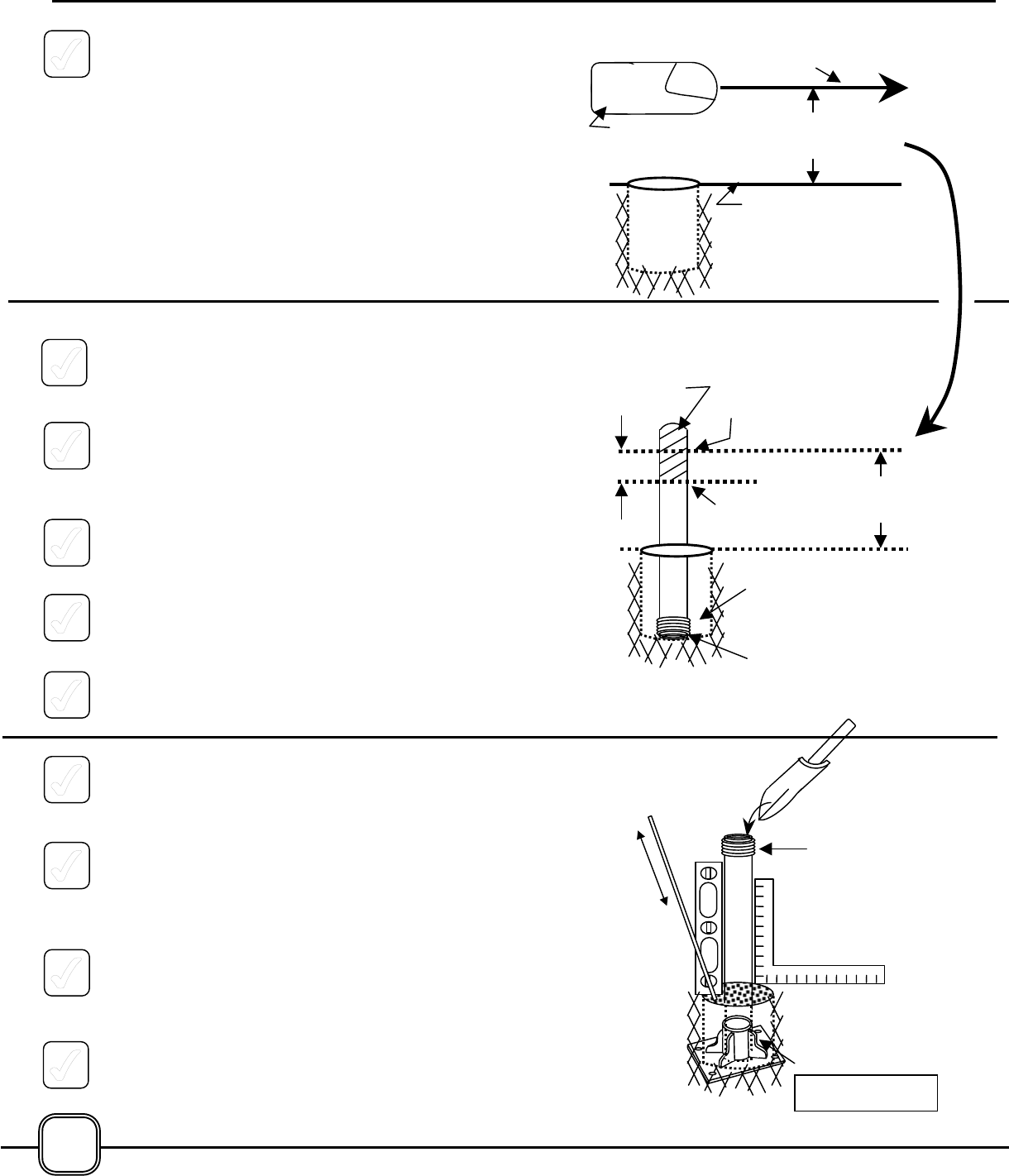
2. Determine the desired height of the beam path
(Refer to Safety Instructions on Page 2)
above the mounting surface of the ground by
measuring the distance from the center of the
front face of the Transceiver downward to the
mounting surface. This is accomplished most
easily by having an assistant hold the
Transceiver in position while the measurement is
being taken, or by propping the Transceiver on a
temporary stand such as a cardboard box, a
stack of bricks, or similar structure.
3. Determine the correct length for the Transceiver
Mounting Post by placing the Post into the hole
upside-down (with the taped threaded collar at
the bottom of the hole.)
4. Transfer the measurement taken in Step 2,
above, to the Mounting Post by placing a mark
on the Post at the correct distance from the
mounting surface.
5. Make a second mark on the Mounting Post at a
point 4½ inches (10 cm) from the first mark,
toward the threaded end of the Post.
6. Remove the Mounting Post from the hole and
cut at the second mark, using a hacksaw or fine
toothed wood saw.
7. Return the Mounting Post to the hole right side-
up (with the taped threaded end upward.)
8. Insert Mounting Post into the Mounting Base as
noted in Step 5 on Page 9. This will add stability
to the Mounting Post.
9. While holding the Mounting Post in a vertical
position, fill the hole with concrete. A
carpenter’s level or framing square will help in
determining when the Mounting Post is plumb
and vertical.
10. Work the concrete into the hole with a slender
rod or trowel to force out any air pockets in the
material, and to assure that the material is tightly
packed around the Mounting Post.
11. For maximum strength and rigidity of the
Mounting Post, additional concrete may be
poured inside of the taped Post, filling it
completely.
Post is
Upside-Down in
4½”
Disca
Desired
Beam Path
Mark
Cut
Desired Beam
Pth
Transcei
Ground
Surfa e
Desired
Beam Path
Taped
Concrete
10
Taped
12. Do not attempt to mount the Transceiver onto
the Mounting Post until the concrete has had a
chance to set – this will take several hours,
depending upon local conditions.
INSTALLING THE TRANSCEIVER MOUNTING
POST TO A WALL OR OTHER VERTICAL
SURFACE
The Transceiver may be mounted to a vertical
surface such as a wall, fence or post by using the
Mounting Base and sections cut from the
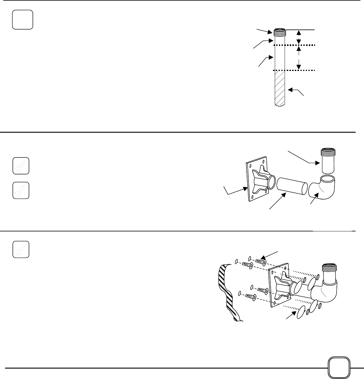
Transceiver Mounting Post. In addition, one 90
degree, 1½ inch elbow is required, as well as a small
quantity of the provided epoxy for bonding the parts
together, and hardware for installing the Mounting
Base to the selected surface.
The 90 degree elbow is a standard plumbing item
available in hardware or home improvement stores.
Its full technical name is: 1½ inch, Schedule 40,
PVC, Slip-by-Slip, 90 degree Elbow. Painting the
elbow using gray spray paint is optional.
1. Cut the Transceiver Mounting Post into two
sections, “A” & “B” as shown above.
2 Bond the parts together using epoxy, keeping
Section “A” vertically aligned with the vertical
edge of the Transceiver Mounting Base.
3. Attach the Transceiver Mounting Base assembly
washers and the screw holes on the four corners
of the Base, into suitable anchors. A minimum of
size #8 screws is recommended for this
purpose.
**Need to get sizing and descriptions
NOTE: Mounting the unit to a wire fence, or other
flexible or movable surface is not recommended.
Such installations virtually guarantee false alarms
due to movement of the laser beam.
3”
6”
Section
“”
Discar
d
Section
“B”
Transce
i
ver
Mounting
Post
Section
“B”
Section
“”
Mount
i
ng
Base
90 Degree
PVC Elbow
Washers
1C
Insert
s
11
*Not
ATTACHING THE
TRANSCEIVER TO THE
MOUNTING POST
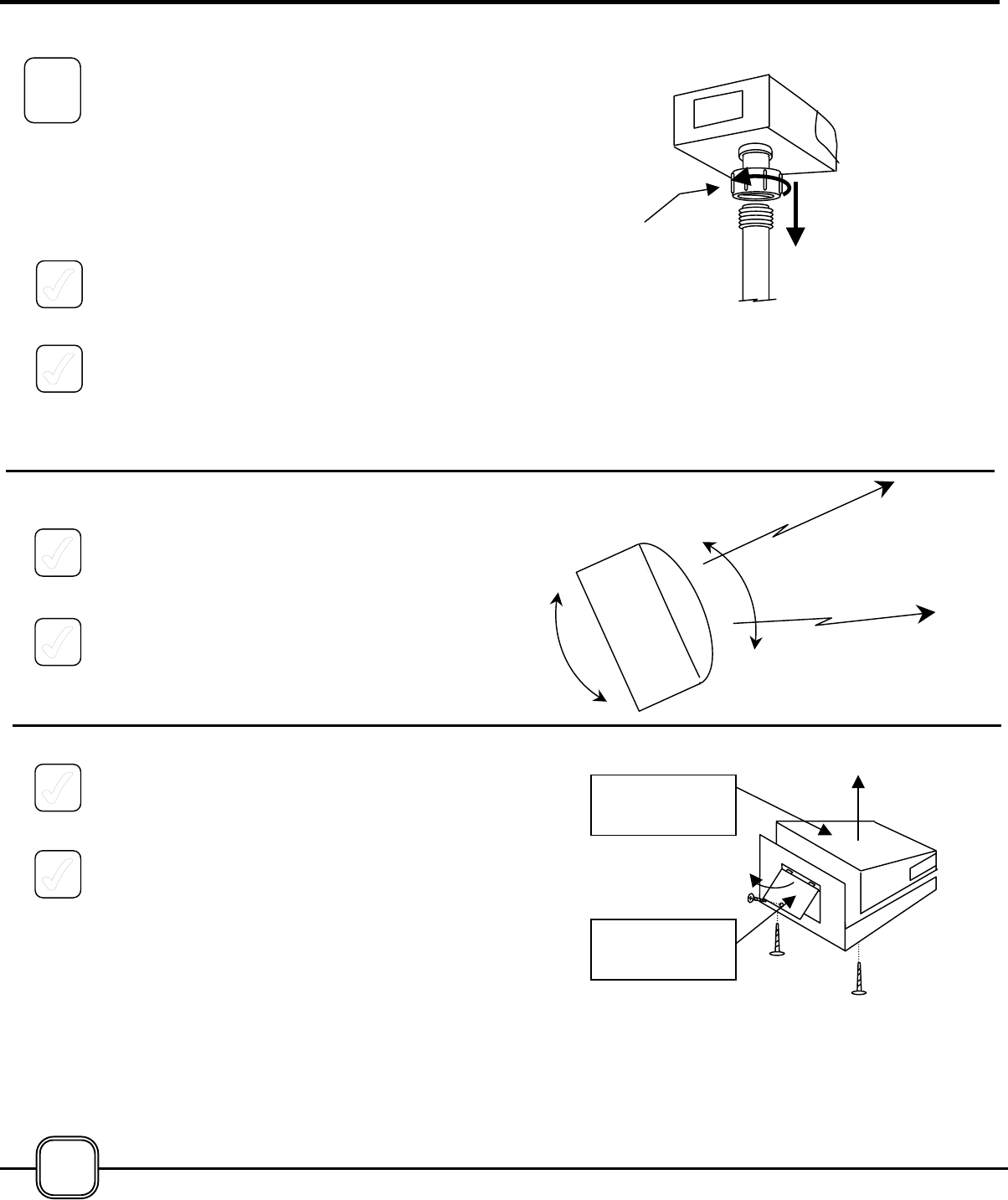
The threaded union on the bottom of the Transceiver
mates to the threaded portion at the top of the
Mounting Post.
1. Remove masking tape from Transceiver
Mounting Post.
2. Align the union on the Transceiver with the top
of the Mounting Post and engage the threads by
rotating the union clockwise (as viewed from
above the unit.) Do not tighten the union
completely at this time.
2. Rotate the transceiver left or right until the front
face of the unit is pointing in the approximate
direction of the desired beam path or paths.
3. Tighten the union on the bottom of the
Transceiver. Hand-tight is sufficient.
4. Remove the Transceiver Top Cover from the
Transceiver by removing the two Phillips screws
from the bottom of the unit, and lifting the cover
straight upward.
5. Remove the Transceiver Door from the rear of
the Transceiver by removing one screw and
lifting the bottom of the cover away from the
Transceiver until the tabs at the top of the cover
disengage.
2
12
Union
Transcei
ver Door
Transcei
ver Top