Caretaker Systems 3-204-35 User Manual manual 7of8
Caretaker Systems, Inc. manual 7of8
Contents
manual 7of8
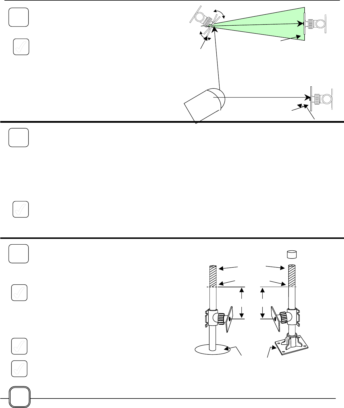
IF MIRRORS WERE INSTALLED…
If Mirrors were installed in either or both Beam Paths,
those mirrors must be adjusted to "bounce" the laser
beam onward to a Reflector.
1. Refer to pages 15 - 19 for installation details on
adding the Swivel Mount for the Reflector. The
mounting may be a Mounting Post in a Mounting
Base or directly into a hole in the ground; or by
attaching a Swivel Mount
2. After completing the installation of the final
Reflectors, the Mirrors must be adjusted to
cause the Laser Spot to appear in the center of
the Reflector. Be gentle - a small movement of
the Mirror will cause the laser beam to swing
over a wide arc.
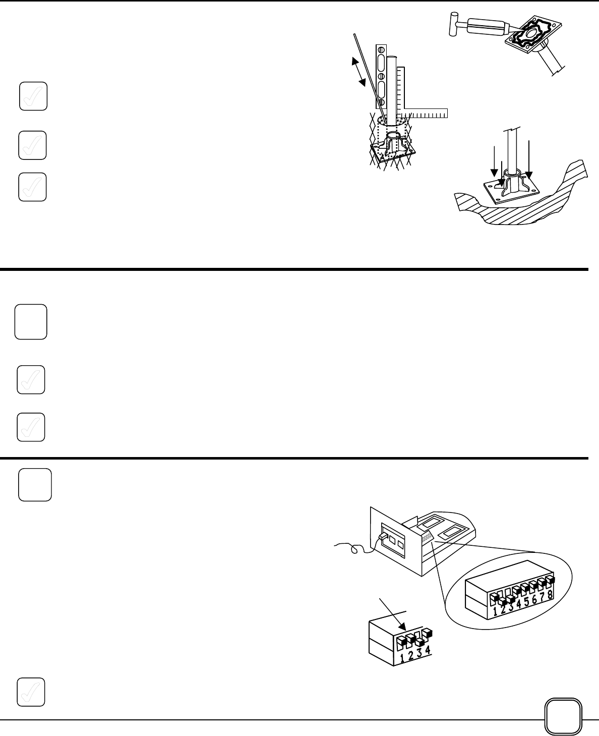
COMPLETING THE
INSTALLATION
1. If desired, the Mounting Posts may be cut to
remove some of the excess.
It is recommended that at least 12 inches (.30
meter) be left above the beam path to allow for
future adjustment.
The Posts are easily cut with a hacksaw or fine-
toothed wood saw.
2. Install a Mounting Post Cap onto the top of each
Mounting Post to cover the cut edge and to
prevent water from collecting in the Post.
3. Realign each Post-mounted Mirror or Reflector
so that the Laser Spot is in the approximate
center of each Mirror or Reflector.
12"
Discar
Cut
Temporary
Filli
Not
Permanently
A
tt h d
Mounti
ng
8B
TIME FOR A QUICK SURVEY OF THE SYSTEM
A
t this point the Transceiver and any wall mounted Swivel Mounts have been permanently mounted
and all of the Mirror/Reflector Mounting Posts have been temporarily installed. A Laser Spot should be
visible in the approximate center of each Mirror and Reflector in the system.
Now is a good time to pause in the installation process to look for any potential problem areas in the
system. Try to visualize the changes that might take place in the future – will some plants grow to
interfere with the beam path? Will an unnoticed door or gate open into the beam path? Will excessive
single stream garden or lawn sprinklers interfere with the system?
IIf all is well, it is time to complete the installation…
Reflecto
Reflect
Mirro
9
10
20
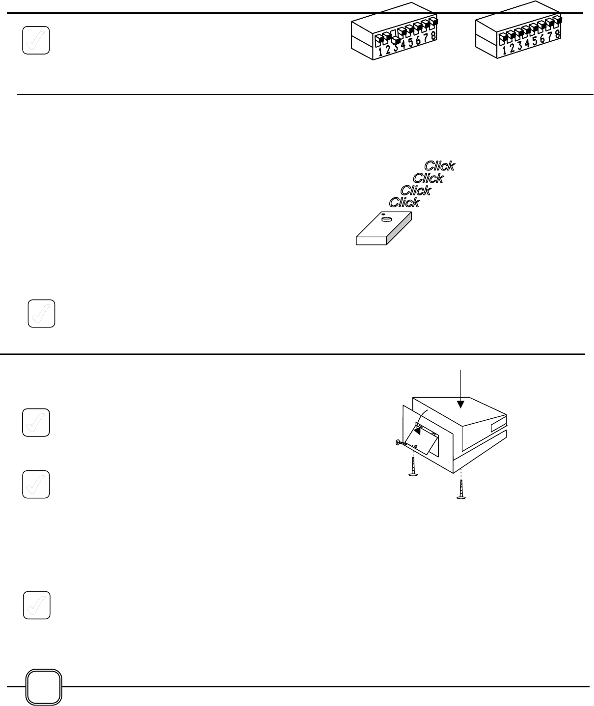
COMPLETING THE INSTALLATION OF EACH
MOUNTING POST
NOTE: START AT THE FIRST POST IN EACH
BEAM PATH AND WORK OUTWARD TOWARD
THE REFLECTOR. WORK ON ONE MOUNTING
POST AT A TIME, REALIGNING THE LASER DOT
ON EACH MIRROR OR REFLECTOR BEFORE
MOVING ON TO THE NEXT POST.
1. If the Mounting Post is inserted into a hole in the
ground, follow the procedures described on
page 10 for adding concrete to the hole.
2. If the Mounting Post is attached to a Mounting
Base, follow the procedures described on page
9 for applying epoxy to the unit.
MAKE SURE THE LASER DOT IS CENTERED ON
EACH MIRROR OR REFLECTOR, AND THAT
EACH MIRROR IS BOUNCING THE LASER BEAM
TO THE CENTER OF THE NEXT REFLECTOR.
THE FINAL STEPS…
This completes the installation of the major components of the Prevent system. Now is the time to
install any of the optional features such as the Indoor Alarm or Pet Safety Alarm. Follow the
instructions packaged with the options.
The final step in the installation process is to activate and test the system.
But first - just to make sure - CHECK TO SEE THAT A LASER SPOT APPEARS IN THE CENTER
OF EACH MIRROR AND REFLECTOR. Right now is the best time to "tweak" the system to
assure that the system will function correctly, with a minimum number of false alarms, and provide
years of trouble-free security and peace of mind.
Make sure that all of the Unions are snug, and that all of the Phillips screws on the Swivel Mounts
are tight.
Secure power cable to Transceiver Mounting Post with included Cable ties.
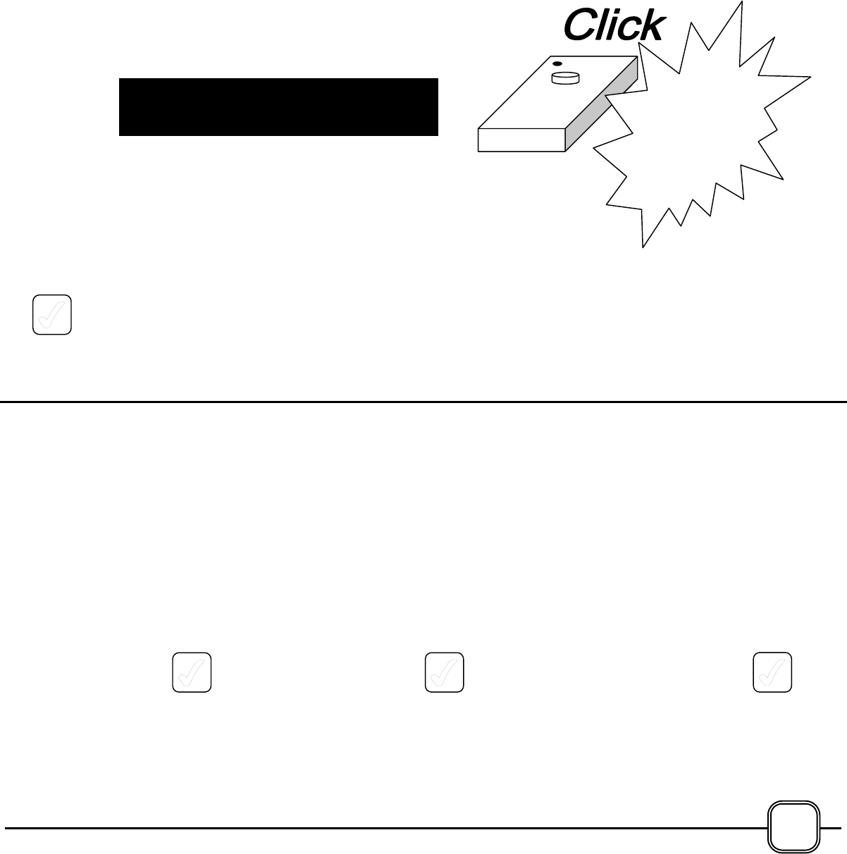
ACTIVATING THE
SYSTEM is a four step process. First, the
DIP switch setting must be changed to signal the
equipment to end the Installation Mode. Then, the
Remote Controller must be activated in its Set-up
Mode, next the cover will be installed on the
Transceiver, and finally, the Remote Controller will be
used to transmit a START signal to the system.
STEP 1 - SETTING THE DIP SWITCH
The Installation Mode is controlled by switch #2 on
the DIP switch located inside of the Transceiver.
1. To cancel the Installation Mode, move the #2
switch handle UPWARD. The GREEN indicator
light is ON solid - it stops flashing.
Factory
Settings #2 &
#3 DOWN,
ll Oth UP
Move
#2 UP
11
12
Concrete
In a Hole
Epoxy on a
Base Mount
Press Down
Firml
21
2. All of the other switches should remain at their
factory settings, except for switch #3 which may
have been moved UPWARD to select single
laser operation.
STEP 2 –
ACTIVATING THE REMOTE CONTROLLER
The Remote Controller provided with the Prevent
system is a low-power, single channel, radio
frequency transmitter. It is intended to be used
within the immediate pool area by a supervising
individual.
It does not have to be aimed at the Transceiver, as a
TV remote control must be aimed at a television set:
it functions more like the remote controls used with
garage door openers.
A battery was installed in the Remote Control
Transmitter at the factory. The Remote Control is
ready to use.
1. Click the button on the Remote Controller 4
times. (Each click must come within one
second of the preceding click.) The system will
respond as shown at the right.
STEP 3 - INSTALLING THE COVERS
1. Lower the top cover onto the Transceiver and
fasten by inserting the two mounting screws
upward through the holes in the Transceiver
bottom, and tighten into the Transceiver Top
Cover.
3. Install the Transceiver Door by engaging the two
tabs on the top edge of the cover into the mating
slots in the Transceiver Bottom. Swing the Door
downward into position and fasten with the
single screw provided.
AND, ONE LAST TIME - MAKE SURE THERE IS A LASER SPOT IN THE
CENTER OF EACH MIRROR AND REFLECTOR.
22
•Lasers are
O
•GREEN Indicator Light is
•Alarm CHIRPS Every 2
i
4
-OR
BOTH Lasers RIGHT Laser
STEP 4 - TRANSMITTING THE START SIGNAL
At this point a single click of the Remote Controller
will send a special START signal to the system. The
following sequence of events will take place:
• The lasers will turn OFF
• The alarm will CHIRP for 15 SECONDS
• The lasers will turn ON
The system will then be fully operational. The
alarm will sound any time the beam path is
broken. The alarm is VERY LOUD, and may
startle nearby persons who may not be expecting
the intensity of the sound. Consider notifying
the closest neighbors. Consider your pets.
1. At this point, click the Remote Control ONCE.
The following sequence of steps will serve to test the
Prevent system and to familiarize a user with the
operation and capabilities of the system.
Syste
the
Start
1
23
BE PREPARED
TESTING THE SYSTEM
TEST 1
• Walk through a beam path.
• The alarm will SOUND.
• CLICK the Remote 3 TIMES.
• The alarm will turn OFF
Repeat this Test on the second
beam path, if installed.
TEST 2
• CLICK the Remote 1 TIME.
• Walk through a beam path.
• Alarm CHIRPS every 3 SECONDS.
• GREEN Light FLASHES.
• System resets in 15 SECONDS
TEST 3
•
••
• Unplug Power Cable Assembly.
• Walk through beam path.
• The alarm will SOUND.
• CLICK the Remote 3 TIMES.
• The alarm will turn OFF
• Plug Transformer IN.
(This test confirms that batteries
are installed and OK.)
Proceed to the next page for a description of all of the
Remote Controller functions.