Caretaker Systems 3-204-35 User Manual manual 5of8
Caretaker Systems, Inc. manual 5of8
Contents
manual 5of8
INSTALLING THE
POWER CABLE
ASSEMBLY
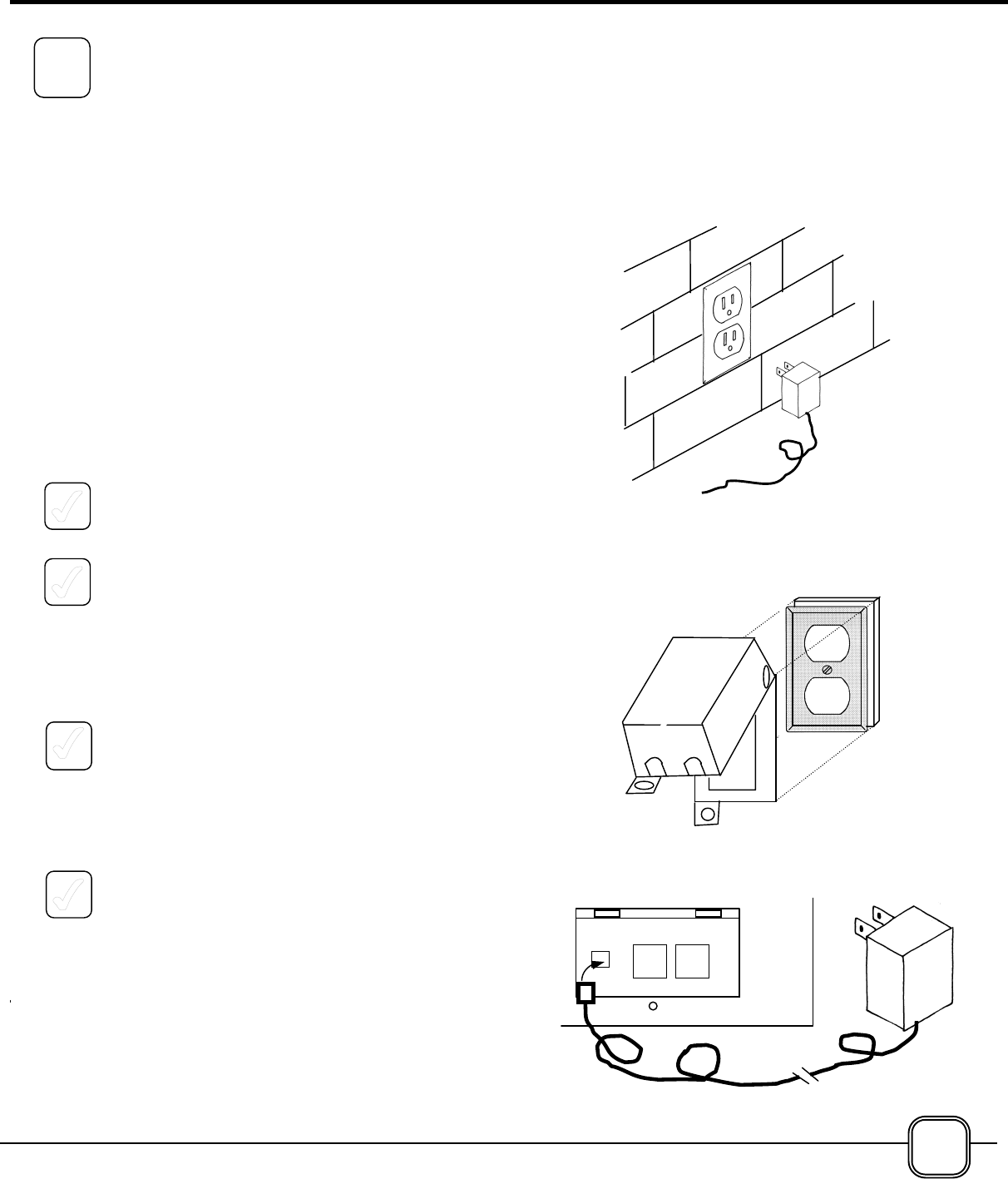
The system is supplied with a Power Cable
Assembly, equipped with a 50 foot (15 meters) long,
low-voltage power cable. The end of the cable has a
factory-installed plug that mates with a socket in the
Transceiver.
The Transformer must be plugged into a standard
120-volt receptacle. It is best if this receptacle is not
controlled by a switch. If it is controlled by a switch,
consideration should be given to marking the switch
to indicate that the Prevent system is controlled by
that switch; or, a qualified electrician can remove the
switch
1. DO NOT PLUG THE TRANSFORMER INTO
THE WALL RECEPTACLE AT THIS TIME.
2. Starting at the receptacle end, route the cable
toward the Transceiver. The cable may be buried
in the ground, routed along the edge of decking
or fastened to woodwork using insulated staples
or non-metallic fasteners. Route the cable so
that it is out of the way, and does not create a
tripping hazard. Excess cable may be formed
into a knotted loop at the Transformer.
3. If the selected receptacle is located outdoors
where it may be subjected to direct rain, a
weatherproof cover, such as the one shown at
the right, is recommended. These covers are
available at hardware and home improvement
stores.
4. At the rear of the Transceiver, insert the power
plug on the end of the power cable assembly into
the mating socket on the left side of the panel.
Do not force the plug into the socket – it will fit
only one way. If it fails to snap into place, rotate
the plug, and try again.
NOTE: Because the Power Cable Assembly is not
plugged into the wall outlet at this time, nothing will
happen when the power plug is inserted into the
Transceiver. This is normal.
13
3
*Cover Not
In luded
SELECTING THE
OPERATING MODE
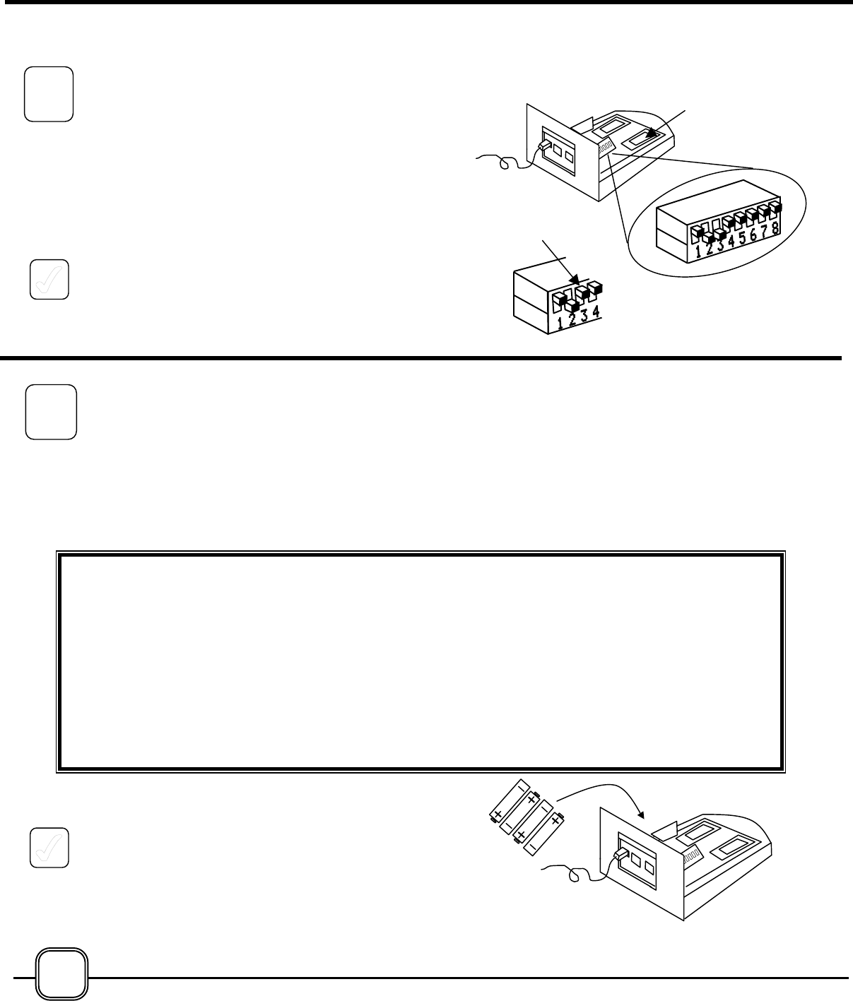
If the system configuration requires only one beam
path, one of the two lasers in the Transceiver may be
turned OFF. The RIGHT-SIDE laser (when viewed
from the rear of the Transceiver) is controlled by
switch #3 on the DIP switch located inside of the
Transceiver.
1. To turn the right-side laser OFF, move the #3
switch handle UPWARD. All of the other
switches should remain in their factory settings,
as shown at the right.
INSTALLING THE
BATTERIES AND
APPLYING ELECTRIC
POWER
1. Install the four “AAA” size batteries into the
battery holder inside of the Transceiver. Note the
polarity markings on the holder, and install the
batteries accordingly.
PLEASE NOTE:
IN THE NEXT STEPS BATTERIES WILL BE INSTALLED AND THE POWER CABLE ASSEMBL
Y
WILL BE PLUGGED INTO ITS ELECTRICAL OUTLET. ELECTRIC POWER WILL BE APPLIED TO
THE TRANSCEIVER, AND THE LASER BEAMS WILL BE ACTIVATED. THIS WILL CREATE
BEAMS OF BRILLIANT RED LIGHT EMERGING FROM THE FRONT OF THE TRANSCEIVER.
A
BRIGHT RED “LASER DOT” CAN BE SEEN ON ANY SURFACE OR OBJECT THAT THE BEAM
STRIKES. DURING THE INSTALLATION AND SETUP PHASE THE LASER BEAMS WILL BE ON
CONTINUOUSLY. DO NOT ALLOW THE BEAM TO REACH THE EYES OF ANY HUMANS O
R
PETS. IF THE LASER DOT CANNOT BE SEEN ON ANY NEARBY OBJECT, HOLD A PIECE OF
WHITE PAPER IN FRONT OF EACH LASER TRANSMITTER TO DETERMINE THE BEAM PATH.
THE BEAMS MAY BE TURNED OFF ONLY BY UNPLUGGING THE POWER CABLE FROM THE
OUTLET, AND REMOVING THE BATTERIES FROM THE TRANSCEIVER.
14
Right-
Side
Move
#3 UP
Factory
Settings #2 &
#3 DOWN,
ll Oth UP
4
5
2. AT THIS POINT, PLUG THE POWER CABLE
ASSEMBLY INTO THE ELECTRICAL OUTLET.
The lasers have been energized.
The GREEN indicator light is FLASHING, indicating
the system is in the Installation/Set-Up Mode. In this
Mode the laser beams will stay ON for beam path
alignment purposes, and the alarm will NOT sound
when the beam path is broken.
The RED indicator light is OFF. This is the battery
condition indicator. When the Red indicator turns
ON, it indicates that the four batteries in the
Transceiver need replacing.
INSTALLING
MIRRORS AND
REFLECTORS
The first step in mounting the Mirrors and Reflectors
is to determine the location for each unit. It may be
helpful to review the Typical Installation diagrams on
pages 4 and 5, and the Installation Considerations
on pages 6 and 7.
Keep in mind the most important feature of a laser
beam system – the beam travels in a perfectly
straight line called the beam path, and nothing can
be allowed to interfere. There can be no plants,
buildings, furniture or toys in the beam path.
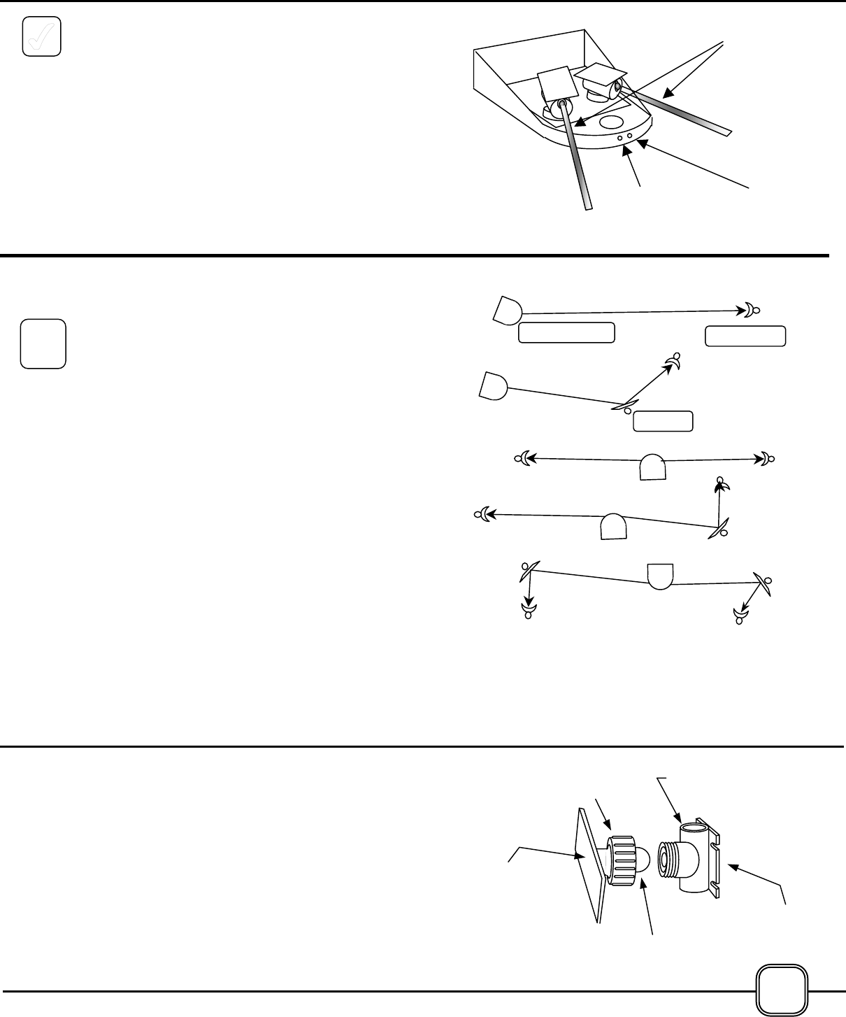
The primary goal at this point is to place the Mirrors
and Reflectors so that the laser beam travels
unimpeded from the Transceiver, along the beam
path until it gets to a Reflector.
Each beam path must begin at the Transceiver and
end at a Reflector.
If it is necessary to “bend” the beam path around a
corner, or to jog around an obstacle, a Mirror may be
installed in the beam path.
THE VERSATILE SWIVEL MOUNT
The Swivel Mount was designed to make the
installation of Mirrors and Reflectors as simple as
possible.
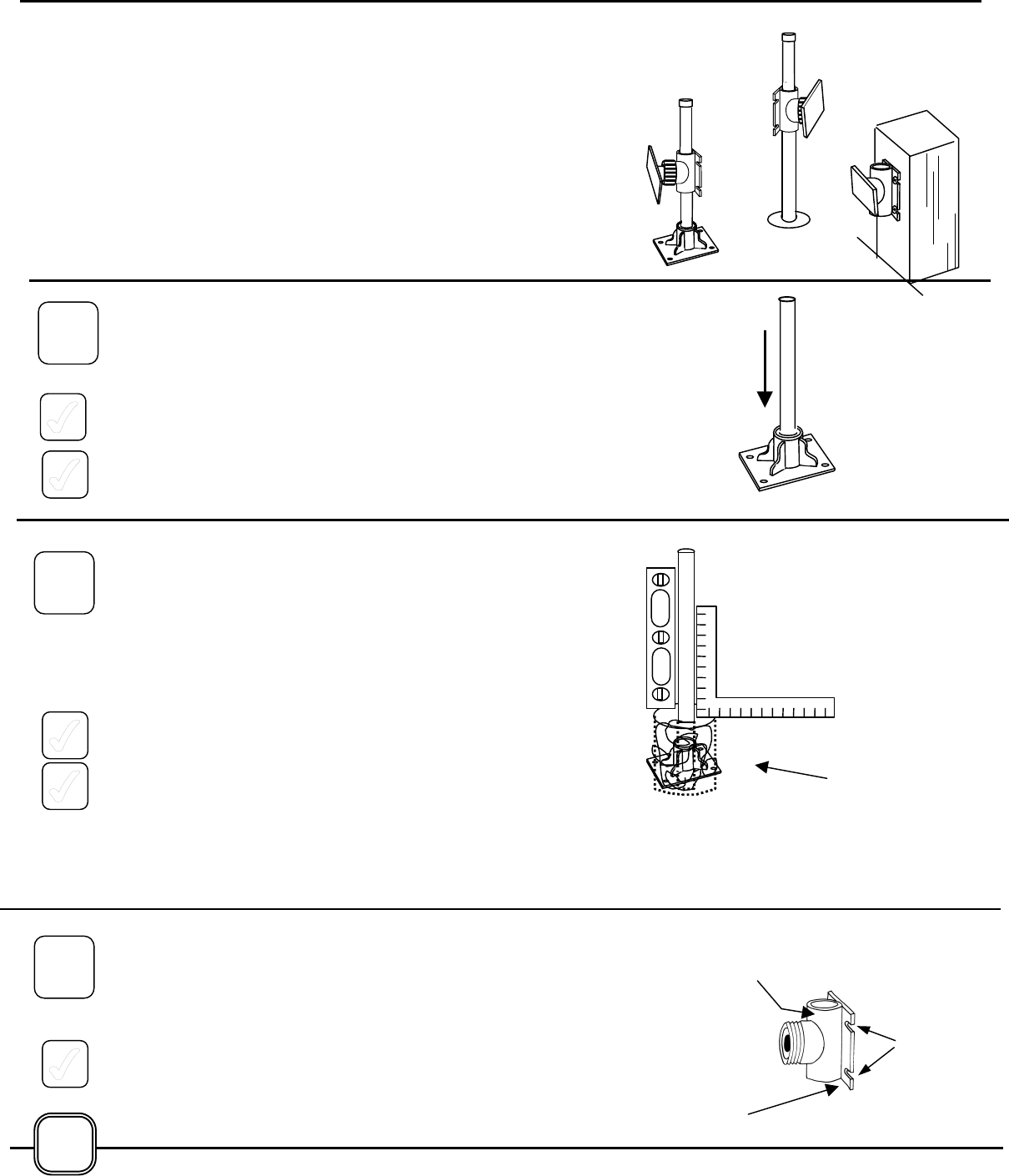
The Fitting consists of two sections: the Swivel
Mount, and the Ball Assembly which is attached to
the back of the Mirrors and Reflectors.
The Swivel Mount can be attached to a Mirror/
Reflector Mounting Post, wall, fence or pillar by
means of its Mounting Flange.
The Ball Assembly allows the attachment and
adjustment, of either a Mirror or a Reflector.
Transce Reflec
Mirr
Ball
bl
Mirror
or
fl
Mounti
ng
Swivel Mount
Union
GREENRED
Idi t
Laser
6
15
INSTALLATION OPTIONS
Like the Transceiver installed earlier, Mirrors and Reflectors
may be mounted onto the pool deck, patio surface, or to
some other solid surface using the Mirror/Reflector Mounting
Bases and the Mirror/Reflector Mounting Posts supplied.
Or, these Mounting Posts may be set in concrete directly into
holes in the ground.
As a third option, the Mirror/Reflector Mounting may be
installed directly onto a wall, fence or pillar by using the
supplied epoxy or purchased hardware applied to the
mounting flange.
PREPARING TO MOUNT WITH A MOUNTING BASE
1. Press a Mounting Post firmly into the socket of a
Mounting Base. The supplied epoxy glue should be
used for a permanent connection. Repeat this for each
Mirror/Reflector that requires a Mounting Base. DO NOT
CUT THEM TO LENGTH, AND DO NOT FASTEN THEM
IN PLACE AT THIS TIME.
2. Set each Mounting Base and Post in the approximate
location that you have selected for each Post-mounted
unit.
PREPARING TO MOUNT INTO A HOLE
Mirrors and Reflectors may be installed directly on a
Mounting Post Installed in a hole in the ground. Insert the
Mirror/Reflector Mounting Post into the hole and applying
concrete to hold the Post in an upright, vertical position.
The installation procedure is similar to the installation of the
Transceiver Mounting Post described on page 10, with two
significant differences:
1. The Posts are not cut to length until after initial
alignment of the system.
2. To allow for easy system alignment, the concrete
should not be added to the holes until the alignment is
completed. The Mounting Posts should be held in a
vertical and plumb position by packing some temporary
filling into the hole, around the Post. Crumpled
newspaper, crushed cardboard, or rocks work well for
this purpose.
PREPARING TO MOUNT TO A WALL
Preparing to mount Mirrors and Reflectors to a wall, fence or
other vertical surface is simply a matter of determining where
the Swivel Mount will be installed; and what type of fasteners
or adhesive will be used.
Hold the Swivel Mount against the proposed mounting
surface to determine how the mounting holes can be used to
accomplish the installation. When this has been done, set
the Swivel Mount down close to its final installation point, and
proceed to the next step.
16
Mounting
Base &
Mounting
Mounting
Post in
Swivel
Mount
Attached
ll
Tempora
ry
Filli
Swivel Mount
Mounti
ng
Mounting
Flange
6A
6B
6C