Caretaker Systems 3-204-35 User Manual manual 6of8
Caretaker Systems, Inc. manual 6of8
Contents
manual 6of8
INSTALLATION AND
ALIGNMENT
Select from the following CONFIGURATIONS and
follow the appropriate instructions:
CONFIGURATION 1: FIRST ITEM IN THE BEAM
PATH IS A POST MOUNTED MIRROR OR
REFLECTOR
NOTE: THE MOUNTING POSTS HAVE NOT BEEN
PERMANENTLY ATTACHED AT THIS POINT.
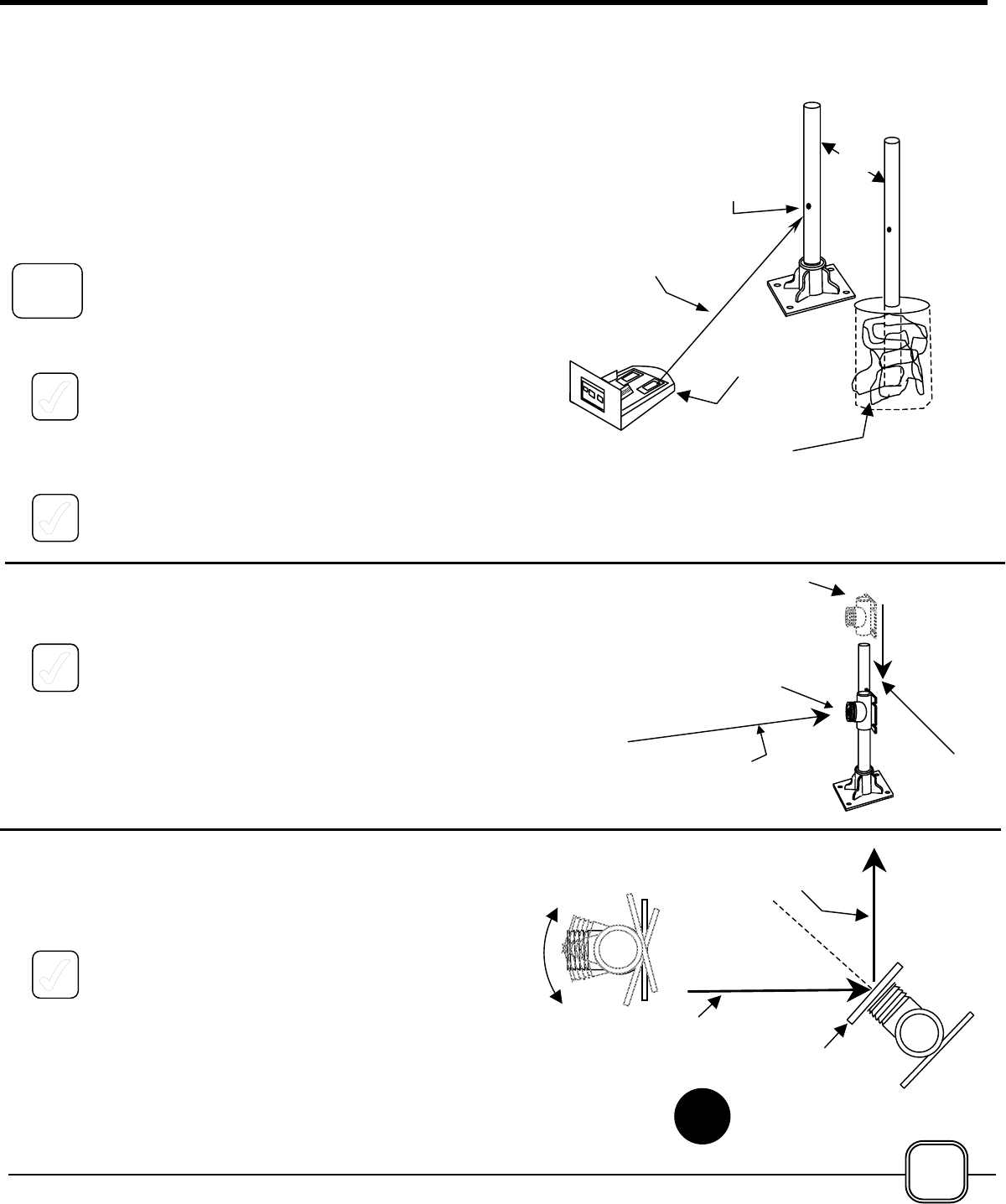
1. At the Transceiver, while holding the laser mount
to prevent it from turning, loosen the Union
under the laser mount by rotating it clockwise as
viewed from above. Aim the laser until it is
hitting the Mirror/Reflector Mounting Post at the
desired height. The beam will be readily seen
as a bright red spot on the Mounting Post.
2. Tighten the Union, making sure you have not
moved the laser.
ATTACH A SWIVEL MOUNT TO EACH POST
1. Slide a Swivel Mount downward over the
Mounting Post until the Laser Spot appears in
the center of the face of the Swivel Mount as
shown at the right.
ALIGN THE SWIVEL MOUNT HORIZONTALLY
Rotate the Swivel Mount to the left or right while
viewing the Mounting Post from above.
3a. If a MIRROR is to be mounted onto the Swivel
Mount, rotate the Mount so that it faces a point
approximately half way between the Transceiver
and the selected location for the Reflector. The
Laser Spot should be in the middle of the face of
the Swivel Mount. (See Illustration 3a.)
Laser
Mt
Laser
St
Beam
Pth
OR
Temporary
Fill
Beam Path
From
Beam Path From
Mirror To
Mirro
r
3a.
Beam Path
Laser
Swivel Mount
7A
17
Screw
s
3b. If a REFLECTOR is be mounted onto the Swivel
Mount, the face of the Mount should be
perpendicular to the beam path. The Laser Spot
should be in the middle of the face of the Swivel
Mount. (See Illustration 3b.)
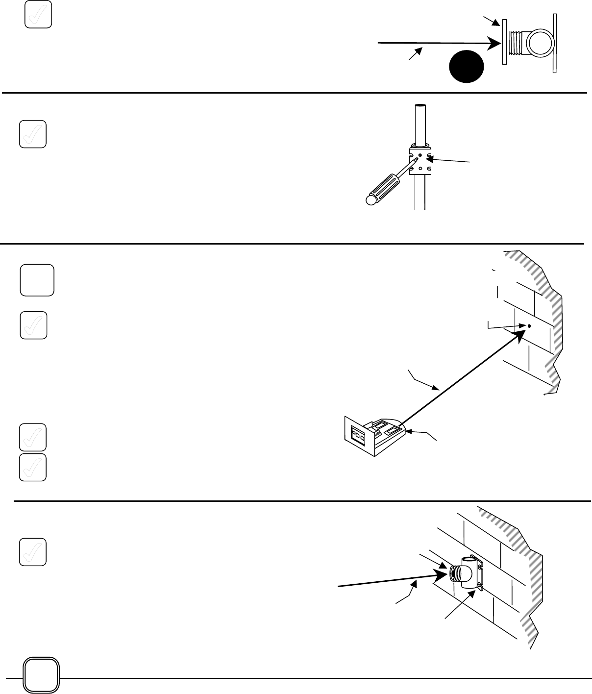
LOCK THE SWIVEL MOUNT TO THE POST
4. While holding the Swivel Mount to prevent it
from turning on the Mounting Post, tighten the
Phillips head screw on the back of the Swivel
Mount.
NOTE: THE MOUNTING POSTS HAVE NOT BEEN
PERMANENTLY ATTACHED AT THIS POINT.
SKIP TO STEP 8
CONFIGURATION 2: FIRST ITEM IN THE BEAM
PATH IS A WALL MOUNTED MIRROR OR
REFLECTOR.
1. At the Transceiver, while holding the laser mount
to prevent it from turning, loosen the Union
under the laser mount by rotating it clockwise as
viewed from above. Aim the laser until it is
hitting the wall or other surface at the proper
height. The beam will be readily seen as a
bright red spot on the wall.
If the surface does not allow the laser spot to be
seen readily, a piece of white paper may he
taped to the surface temporarily.
2. Tighten the Union, making sure you have not
moved the laser.
2. By holding a Swivel Mount against the wall,
determine that it can be mounted so that the
Laser Spot will hit in the center of the face of the
Swivel Mount.
COMPLETE THE INSTALLATION OF A SWIVEL
MOUNT TO A WALL
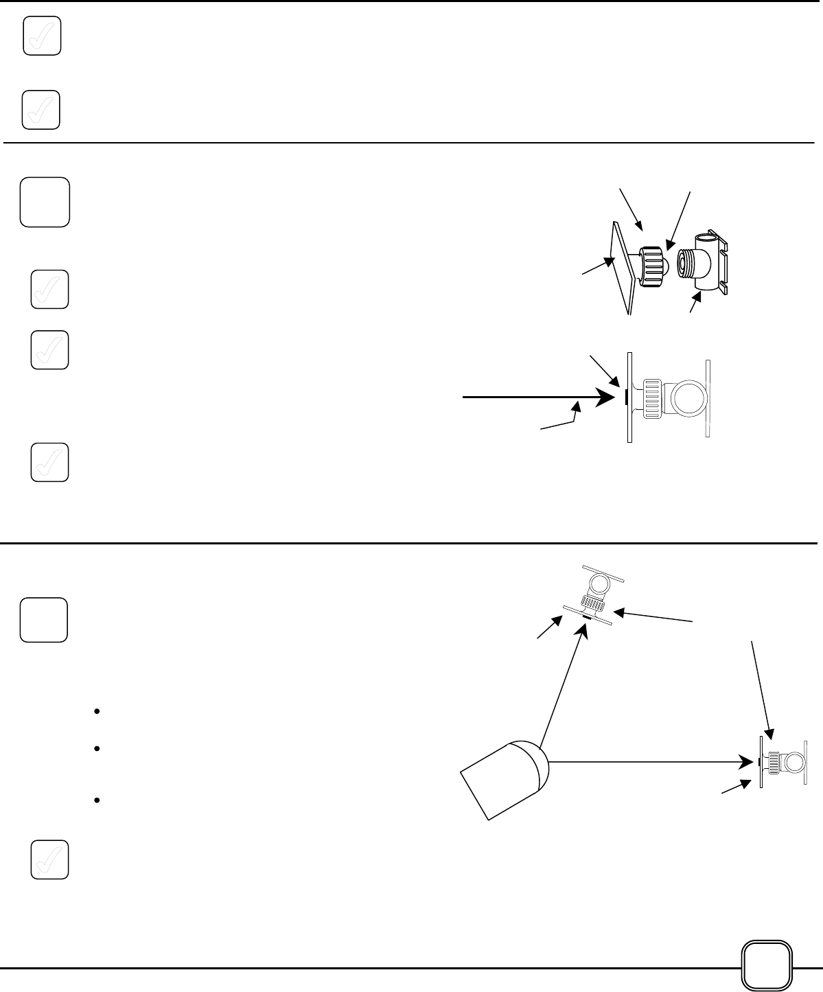
4a. If the Swivel Mount is to be attached with epoxy,
follow the procedures described on page 9 for
applying epoxy to the unit. Use a fresh Mixing
Nozzle.
Press the Swivel Mount firmly against the wall,
making sure the Laser Spot is still hitting the
center of the face of the Swivel Mount. Hold for
2 minutes, then let the adhesive dry for 15
minutes before attaching a Mirror or Reflector to
the Swivel Mount.
Wal
Beam
Pth
Laser
Mt
Laser
St
Phillips
Head
Reflect
Beam Path
From 3b.
W
a
l
Beam
laser
Epoxy or
Hardware
7B
18
4b. If screws are to be used to attach the Swivel
Mount to a wall or other surface, follow the
procedures described on page 11.
5. If both laser beams are being used, repeat
these procedures for the second Beam Path.
ATTACH THE MIRRORS AND REFLECTORS
NOTE - A REMINDER:
The Mounting Posts have not been permanently
attached at this point. Try to keep the Posts from
moving while attaching the Mirrors or Reflectors.
1. Attach the Mirror or Reflector by inserting the
attached ball into the mating ball socket on the
Swivel Mount.
2. Align the threads of the Union with the threads
on the Swivel Mount and rotate the Union
clockwise to tighten. Do not over-tighten -The
Mirror or Reflector should be movable for
adjustment purposes.
3. Remove protective film from Mirrors.
4. The Laser Spot should be readily visible in the
center of the Mirror or Reflector. If it is not, the
Mounting Post may have been moved during
this step. Realign the Mounting Post as
necessary to get the Laser Spot back to the
center of the Mirror or Reflector.
IF ONLY REFLECTORS WERE INSTALLED…
If a single beam system is being installed, with a
Reflector as the only object; or a two beam system
with Reflectors as the only objects in both beam
paths, the Reflectors should now be aiming directly
at the Transceiver, and the Laser Spot should be
visible in the center of each Reflector. If not,
adjustments may be made as follows:
Loosen the Union and move the Reflector right-
left or up-down.
Loosen the Phillips screw on the rear of the
Swivel Mount Tube and rotate the Mount right-
left or slide it up-down on the Mounting Post.
Rotate the Mounting Post right-left.
Proceed to the STEP 9:
“TIME FOR A QUICK SURVEY OF THE
SYSTEM”
Reflect
Reflect
Reflectors Are
Aiming Directly
i
Top View Of
Assembled
i
Laser
Beam
Pth
Bal
l
Mirror
or
fl
Union
Swivel Mount
8
8A Union
19