Chamberlain Group The 8389 Overhead Door and Gate Operator User Manual 01 37718 indd
Chamberlain Group Inc, The Overhead Door and Gate Operator 01 37718 indd
Contents
- 1. User Manual_20160711_v1 - User Manual pt1 HCTDCU
- 2. User Manual_20160711_v1 - User Manual pt2 HCTDCU
- 3. User Manual_20160711_v1 - User Manual pt3 HCTDCU
- 4. User Manual_20160711_v1 - User Manual pt4 HCTDCU
- 5. User Manual_20160711_v1 - User Manual pt5 HCTDCU
- 6. User Manual_20160711_v1 - User Manual pt6 HCTDCU
- 7. User Manual_20160711_v1 - User Manual pt7 HCTDCU
- 8. User Manual_20160711_v1 - User Manual pt8 HCTDCU
User Manual_20160711_v1 - User Manual pt2 HCTDCU
13
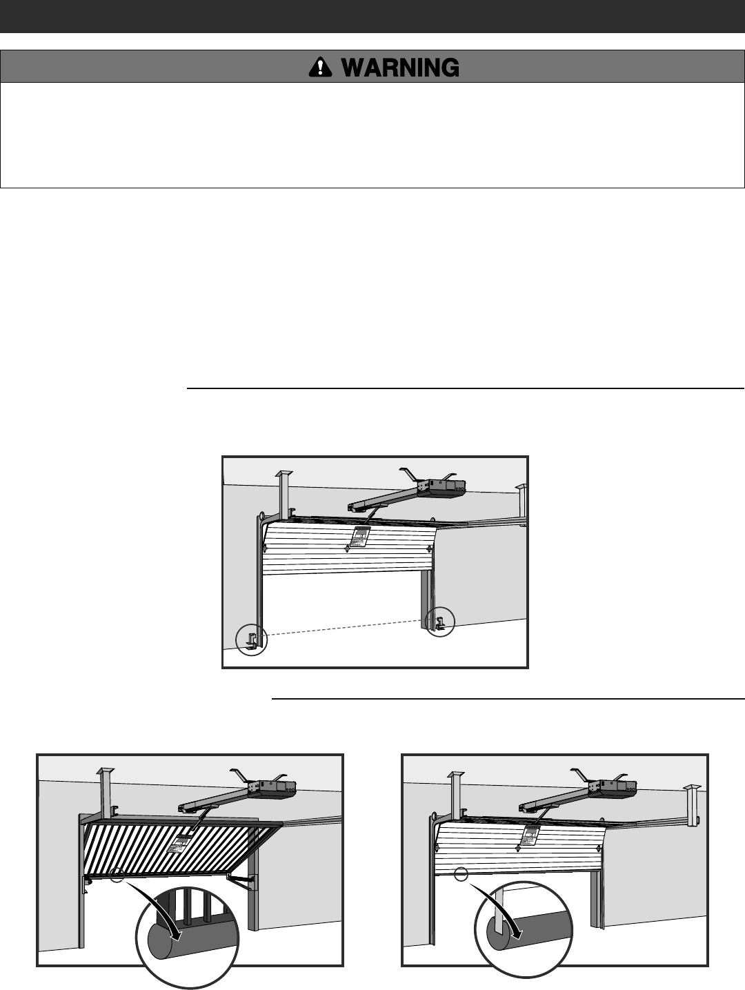
To prevent SERIOUS INJURY or DEATH from a moving gate/door:
• Entrapment protection devices MUST be installed to protect anyone
who may come near a moving gate/door.
• Locate entrapment protection devices to protect in BOTH the open
and close gate/door cycles.
• Locate entrapment protection devices to protect between moving
gate/door and RIGID objects, such as posts or walls.
STEP 5
INSTALL ENTRAPMENT PROTECTION
This operator contains an inherent (internal) entrapment protection system and REQUIRES the addition of an external monitored entrapment
protection system (non-contact photoelectric sensor or contact edge sensor) for EACH entrapment zone prior to gate/door movement. A monitored
device sends a pulsed signal to the operator so the operator is aware of the device. If the operator does not receive the signal from the device it will
not run.
An entrapment zone is every location or point of contact where a person can become entrapped between a moving gate/door and a stationary object.
Your application may contain one or many entrapment zones. Property owners are obligated to test entrapment protection devices monthly. Use only
LiftMaster approved entrapment protection devices (refer to the accessory page).
INSTALLATION
CONTACT SENSORS (EDGE SENSORS)
If the electrically activated edge sensor comes in contact with an obstruction while the gate/door is moving, the gate/door will stop or reverse. The
gate/door will not be able to travel in that direction until the obstruction is cleared.
NON-CONTACT SENSORS
If the photoelectric sensor beam gets blocked while the gate/door is moving, the gate/door will stop or reverse. The gate/door will not be able to travel
in that direction until the obstruction is cleared. Monitored photoelectric sensors MUST be used. If a monitored photoelectric sensor is not working or
loses power or the beam is blocked, then ALL gate/door operation in that direction will stop.
14
STEP 5 continued...
INSTALL ENTRAPMENT PROTECTION
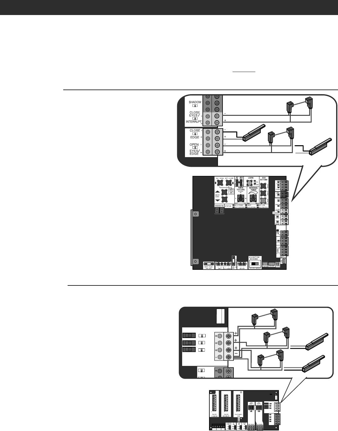
There are three options for wiring the entrapment protection devices depending on the specific device and how the device will function. Refer to the
specific entrapment protection device manual for more information. These entrapment protection device inputs are for monitored devices, which
include pulsed photoelectric sensors, resistive edge sensors, and pulsed edge sensors. NOTE: Only one monitored entrapment protection device may
be wired to each input. Additional entrapment protection devices may be wired to the expansion board.
CONTROL BOARD
CLOSE EYES/INTERRUPT (2 Terminals)
The CLOSE EYES/INTERRUPT input is for photoelectric sensor
entrapment protection for the close direction. When an obstruction is
sensed during gate/door closing the gate/door will open to the full open
position and resets the Timer-to-Close. This input will be disregarded
during gate/door opening.
CLOSE EDGE (2 Terminals)
The CLOSE EDGE input is for edge sensor entrapment protection for the
close direction. When an obstruction is sensed during gate/door closing
the gate/door will reverse to the full open position, disengaging the
Timer-to-Close. This input will be disregarded during gate/door opening.
OPEN EYES/EDGE (2 Terminals)
The OPEN EYES/EDGE input is for photoelectric sensor or edge sensor
entrapment protection for the open direction. When an obstruction is
sensed during gate/door opening the gate/door will stop. This input will
be disregarded during gate/door closing.
EXPANSION BOARD
EYE ONLY and COM
Open or Close Direction Photoelectric Sensors, the functionality is based
on the switch settings (located next to the terminals).
Switch set to CLOSE: gate/door reverses fully when it hits obstruction.
Switch set to OPEN: gate/door stops when it hits obstruction.
EYE/EDGE and COM
Open or Close Direction Photoelectric Sensors or Edge Sensor, the
functionality is based on the switch settings (located next to the
terminals).
Switch set to CLOSE: gate/door reverses fully when it hits obstruction.
Switch set to OPEN: gate/door stops when it hits obstruction.
INSTALLATION
Close Photoelectric Sensors
Close Edge
Open Edge
Open Photoelectric Sensors OR
SHADOW INTERUPT EXIT
SBC
OPN
CLS
STP
COM
EYE
ONLY
EYE/
EDGE
EYE/
EDGE
COM
1
2
3
OPEN
CLOSE
TO MAIN
BOARD
POWER
SBC
OPN
EYE
ONLY
EYE/
EDGE
EYE/
EDGE
COM
1
2
3
OPEN
CLOSE
TO MAIN
BOARD
Photoelectric Sensors
Edge Sensor
Photoelectric Sensors OR
Photoelectric Sensors
OR
Edge Sensor
15
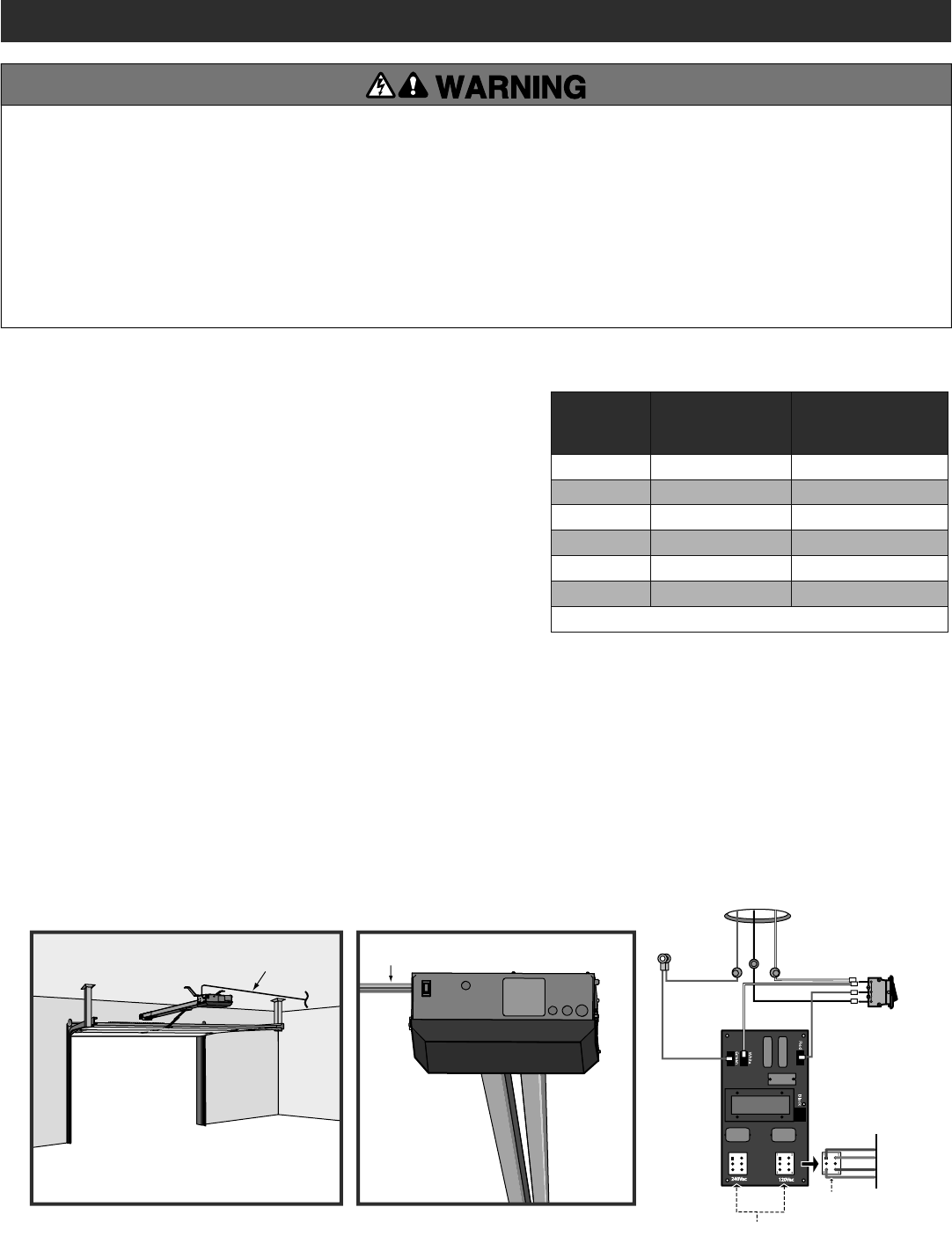
Use UL listed conduit to enclose power wires
Minimum 12 Gauge Ground Wire
Power Wiring Sockets (120 Vac factory default)
EMI BOARD
Input Power Connection
HOT
NEUTRAL
GROUND
Black
Green
White
White
Red
Piggy Back
AC Power
Switch
Power Wiring Connector
STEP 6
POWER WIRING
NOTE: The operator can also be powered by solar panels, refer to the dealer extranet
on LiftMaster.com for more information.
Proper grounding gives an electrical charge, such as from an electrical static discharge
or a near lightning strike, a path from which to dissipate its energy safely into the
earth. The ground wire MUST be a single, whole piece of wire. NEVER splice two wires
for the ground wire. If you should cut the ground wire too short, break it, or destroy
its integrity, replace it with a single wire length. Use the proper type earth ground
rod for your local area. In certain circumstances, metal water pipes may be allowed
for grounding the operator. Check and follow all local codes for proper grounding
procedures.
1. Turn off the AC power from the main power source circuit breaker.
2. Run the AC power wires to the operator.
3. Loosen the nut on the cover of the EMI board and slide the cover back.
4. Connect the green wire to the ground wire using a wire nut.
5. Connect the white wire to NEUTRAL using a wire nut.
6. Connect the black wire to HOT using a wire nut.
7. Ensure the power wiring connector is connected to either the 120 or 240 Vac socket depending on the application. Factory default is 120 Vac.
8. Slide the EMI cover back and tighten nut.
9. Connect the batteries then turn on the AC power. Connect the J15 plug to the control board.
NOTE: The AC Power switch on the operator will turn the incoming 120/240 Vac power ON or OFF. The operator's AC Power switch ONLY turns off AC
power to the control board and DOES NOT turn off battery power.
WIRING
To reduce the risk of SEVERE INJURY or DEATH:
• ANY maintenance to the operator or in the area near the operator
MUST NOT be performed until disconnecting the electrical power (AC
or solar and battery) and locking-out the power via the operator
power switch. Upon completion of maintenance the area MUST be
cleared and secured, at that time the unit may be returned to service.
• Disconnect power at the fuse box BEFORE proceeding. Operator
MUST be properly grounded and connected in accordance with
national and local electrical codes. NOTE: The operator should be on
a separate fused line of adequate capacity.
• ALL electrical connections MUST be made by a qualified individual.
• DO NOT install ANY wiring or attempt to run the operator without
consulting the wiring diagram. We recommend that you install an
edge sensor BEFORE proceeding with the control station installation.
• ALL power wiring should be on a dedicated circuit and well
protected. The location of the power disconnect should be visible
and clearly labeled.
• ALL power and control wiring MUST be run in separate conduit.
AMERICAN
WIRE GAUGE
(AWG)
MAXIMUM WIRE
LENGTH (120 VAC) MAXIMUM WIRE
LENGTH (240 VAC)
14 130 feet (39.6 m) 260 feet (79.3 m)
12 205 feet (62.5 m) 410 feet (125 m)
10 325 feet (99.1 m) 650 feet (198.1 m)
8 520 feet (158.5 m) 1040 feet (317 m)
6 825 feet (251.5 m) 1650 feet (502.9 m)
4 1312 feet (399.9 m) 2624 feet (799.8 m)
Use copper conductors ONLY.
16
WIRING
STEP 7
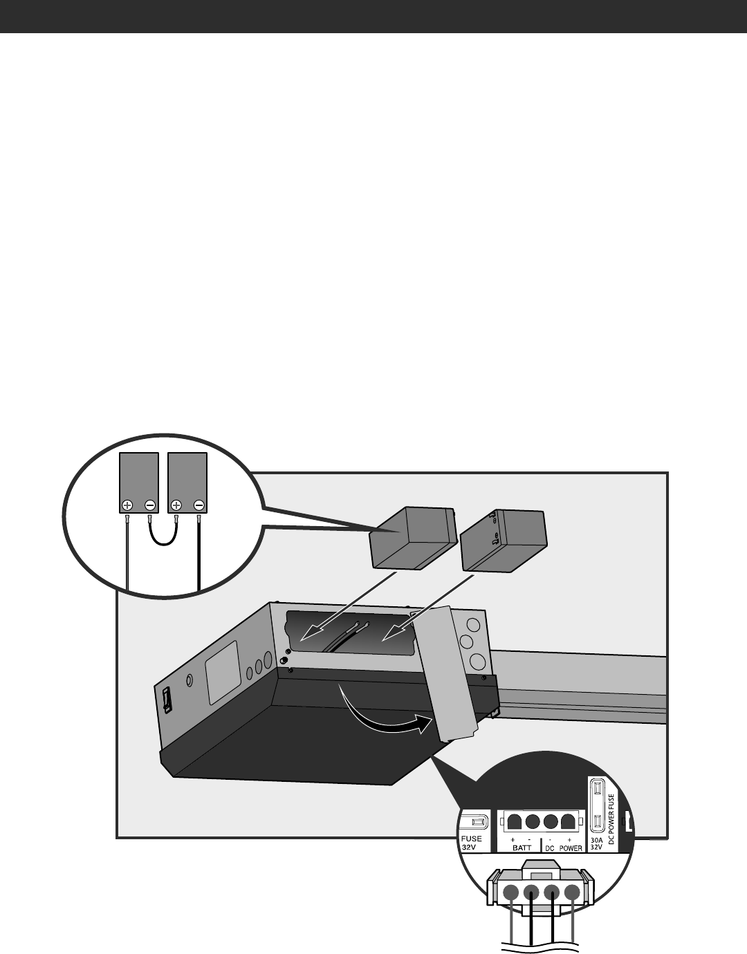
CONNECT BATTERIES
The batteries are charged in the circuit by the integrated transformer. The batteries are for battery backup.
1. Unplug the J15 plug labeled BATT on the control board by squeezing the plug and pulling it from the control board. This disconnects the ac/dc
power to the control board.
2. Loosen the screws on the battery cover and rotate out of the way.
3. Connect the red wire to the positive (+) terminal on one battery and connect the black wire to the negative (-) terminal on the other battery.
4. Connect the black jumper (included with the batteries) between the positive (+) terminal of one battery to the negative (-) terminal of the
other battery.
5. Insert the batteries as shown.
6. Reattach the battery cover.
7. Plug the J15 plug back into the control board. This will power up the control board. NOTE: You may see a small spark when plugging the J15 plug
into the board.
8. Turn ON AC power to the operator.
9. Turn ON the AC power switch on the operator.
Black jumper
provided with
batteries
Black Wire (-)
Red Wire (+)
J15 Plug
17
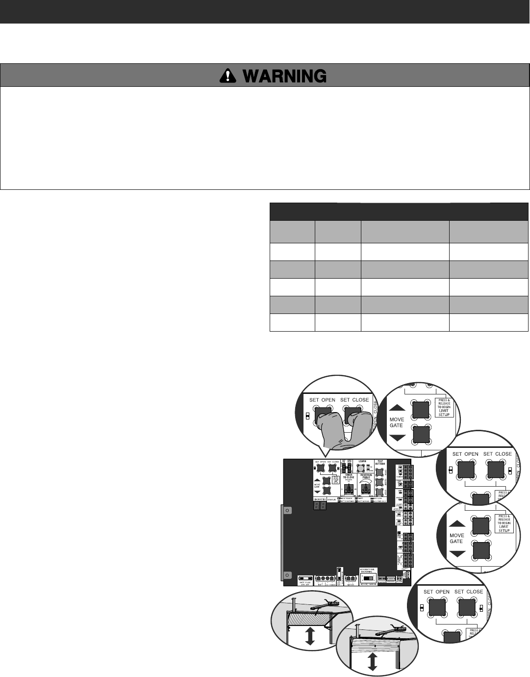
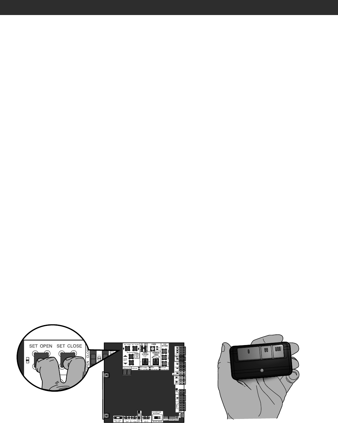
INITIAL LIMITS AND FORCE ADJUSTMENT
The gate/door MUST be attached to the operator before setting the
limits and force.
1. Press and release the SET OPEN and SET CLOSE buttons
simultaneously to enter limit setting mode.
2. Press and hold one of the MOVE GATE buttons to move the gate/door
to the open or close limit.
3. Press and release the SET CLOSE or SET OPEN button depending on
which limit is being set.
4. Press and hold one of the MOVE GATE button to move the gate/door
to the other limit.
5. Press and release the SET CLOSE or SET OPEN button depending on
which limit is being set.
6. Cycle the gate/door open and close. This automatically sets the force.
When limits are set properly the operator will automatically exit limit
setting mode.
INTRODUCTION
Your operator is designed with electronic controls to make travel limit
and force adjustments easy. The adjustments allow you to program
where the gate/door will stop in the open and close position. The
electronic controls sense the amount of force required to open and close
the gate/door. The force is adjusted automatically when you program the
limits but should be fine tuned using the REVERSAL FORCE dial on the
control board (refer to Fine Tune the Force section) to compensate for
environmental changes. The limit setup LEDs (located next to the SET
OPEN and SET CLOSE buttons) indicate the status of the limits, refer to
the table to the right.
The limits can be set using the control board (below) or a remote control
(refer to Limit Setup with a Remote Control in the Programming section).
Setting the limits with a remote control requires a 3-button remote
control programmed to OPEN, CLOSE, and STOP.
NOTE: The Test Buttons on the control board will not work until the limits
have been set.
To reduce the risk of SEVERE INJURY or DEATH:
• Without a properly installed safety reversal system, persons
(particularly small children) could be SERIOUSLY INJURED or
KILLED by a moving gate or door.
• Too much force on gate/door will interfere with proper operation of
safety reversal system.
• NEVER increase force beyond minimum amount required to move
gate/door.
• NEVER use force adjustments to compensate for a binding or
sticking gate/door.
• If one control (force or travel limits) is adjusted, the other control
may also need adjustment.
• After ANY adjustments are made, the safety reversal system MUST
be tested. Gate/door MUST reverse on contact with a rigid object.
LIMIT AND FORCE ADJUSTMENT
ADJUSTMENT
LIMIT SETUP LEDS
SET OPEN
LED
SET CLOSE
LED OPERATOR MODE EXPLANATION
OFF OFF NORMAL MODE Limits are set.
BLINKING BLINKING LIMIT SETTING MODE Limits are not set.
BLINKING ON LIMIT SETTING MODE Open limit is not set.
ON BLINKING LIMIT SETTING MODE Close limit is not set.
ON ON LIMIT SETTING MODE Limits are set.
DIAGNOSTICS
12
3
4
5
6
DIAGNOSTICS
18
2
3
1
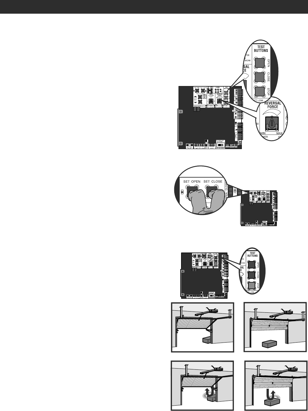
FINE TUNE THE FORCE
The REVERSAL FORCE DIAL on the control board is used for fine tuning
the force in cases where wind or environmental changes may affect the
gate/door travel.
Based on the length and weight of the gate/door it may be necessary to
make additional force adjustments. The force setting should be high
enough that the gate/door will not reverse by itself nor cause nuisance
interruptions, but low enough to prevent serious injury to a person. The
force setting is the same for both the open and close gate/door
directions.
1. Open and close the gate/door with the TEST BUTTONS.
2. If the gate/door stops or reverses before reaching the fully open or
closed position, increase the force by turning the force control slightly
clockwise.
3. Perform the “Obstruction Test” after every force setting adjustment
(see below).
OBSTRUCTION TEST
The operator is equipped with an automatic obstruction sensing feature.
If the gate/door encounters an obstruction during motion, the operator
will automatically reverse or stop the gate/door. After any adjustments are
made, test the operator:
1. Open and close the gate/door with the TEST BUTTONS, ensuring that
the gate/door is stopping at the proper open and close limit positions.
2. Place a solid object under the open gate/door. Ensure that the gate/
door, and the solid object can withstand the forces generated during
this obstruction test.
3. Run the gate/door in the close direction. The gate/door should stop
and reverse upon contact with the solid object. If the gate/door does
not reverse off the solid object, reduce the force setting by turning the
force control slightly counter-clockwise. The gate/door should have
enough force to reach both the open and close limits, but MUST
reverse after contact with a solid object.
4. Repeat test for open direction as necessary.
ADJUST THE LIMITS
After both limits are set and the operator is ready to run, one limit can be
adjusted independently from the other by following steps 1-3 of the Initial
Limit and Force Adjustment section, on page 17.
ADJUSTMENT
LIMIT AND FORCE ADJUSTMENT
DIAGN
19
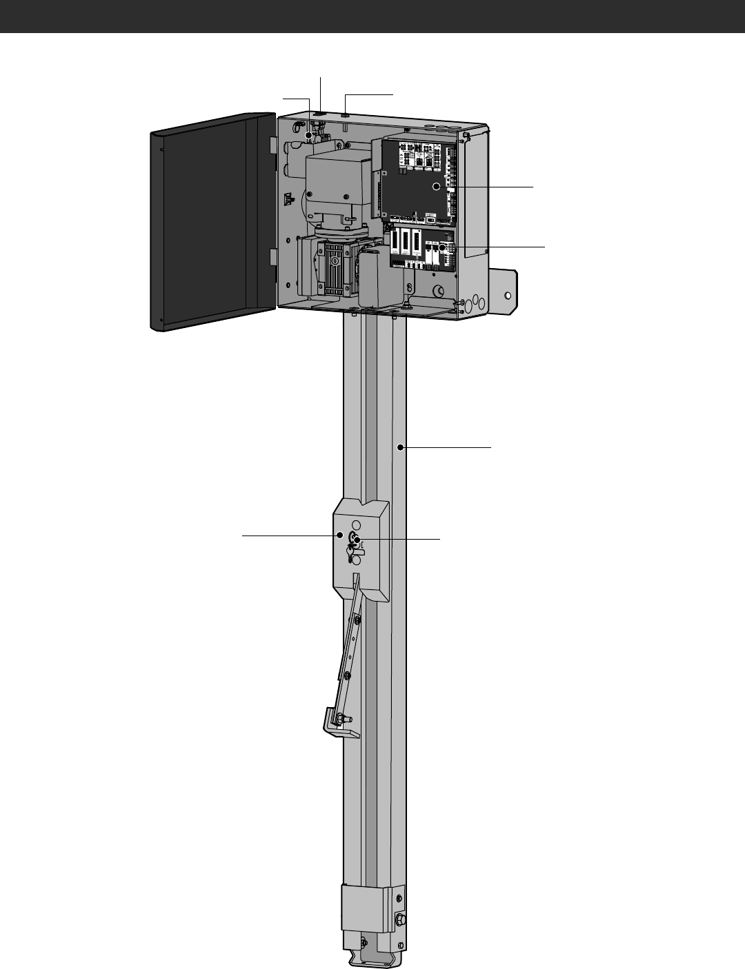
OPERATOR OVERVIEW
EXPANSION BOARD
CONTROL BOARD
RAIL
TROLLEY
RESET BUTTON
AC POWER SWITCH
EMI BOARD
RELEASE RING
20
PROGRAMMING
REMOTE CONTROLS (NOT PROVIDED)
A total of 50 Security+ 2.0® remote controls and 2 keyless entries (1 PIN
for each keyless entry) can be programmed to the operator. When
programming a third keyless entry to the operator, the first keyless entry
will be erased to allow the third keyless entry to be programmed. When
the operator’s memory is full it will exit the programming mode and the
remote control will not be programmed. The memory will need to be
erased before programming any additional remote controls. NOTE: If
installing an 86LM to extend the range of the remote controls DO NOT
straighten the antenna.
There are 3 different options for programming the remote control
depending on how you would like the remote control to function.
Choose a programming option:
The operator will automatically exit learn mode (operator will beep and green XMITTER LED will go out) if programming is successful. To program
additional Security+ 2.0® remote controls or remote control buttons, repeat the programming steps above.
NOTICE: This device complies with part 15 of the FCC rules and Industry Canada (IC) licence-exempt RSS standard(s). Operation is subject to the following two conditions: (1) this device may not cause harmful interference,
and (2) this device must accept any interference received, including interference that may cause undesired operation.
Any changes or modifications not expressly approved by the party responsible for compliance could void the user’s authority to operate the equipment.
This Class B digital apparatus complies with Canadian ICES-003.
This device must be installed in a way where a minimum 8" (20 cm) distance is maintained between users/bystanders and device.
This device has been tested and found to comply with the limits for a Class B digital device, pursuant to part 15 of the FCC rules. These limits are designed to provide reasonable protection against harmful interference in a
residential installation. This equipment generates, uses and can radiate radio frequency energy and, if not installed and used in accordance with the instructions, may cause harmful interference to radio communications.
However, there is no guarantee that interference will not occur in a particular installation. If this equipment does cause harmful interference to radio or television reception, which can be determined by turning the equipment
off and on, the user is encouraged to try to correct the interference by one or more of the following measures:
- Reorient or relocate the receiving antenna.
- Increase the separation between the equipment and receiver.
- Connect the equipment into an outlet on a circuit different from that to which the receiver is connected.
- Consult the dealer or an experienced radio/TV technician for help.
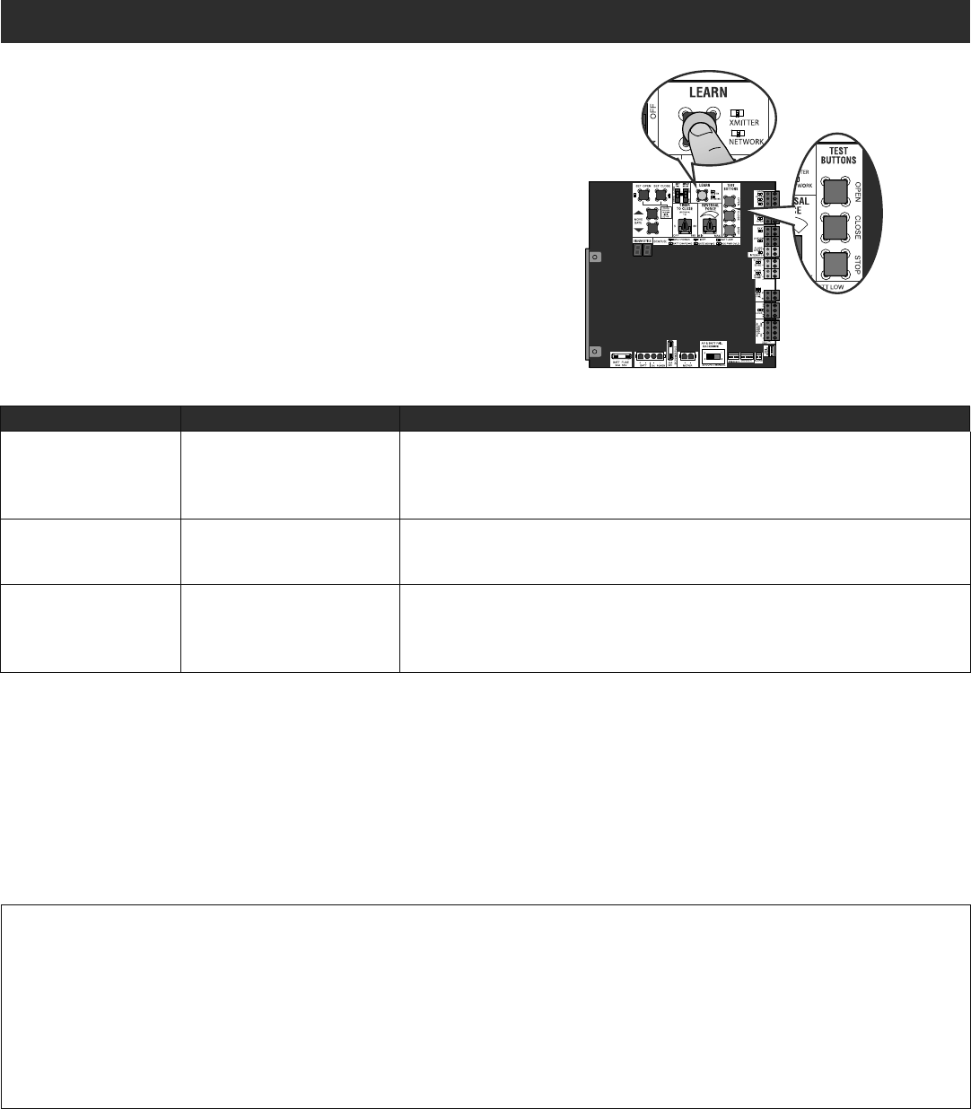
OPTION DESCRIPTION PROGRAM USING OPERATOR'S LEARN BUTTON
Single button as OPEN
only Program a single button on the
remote control for open only.
The Timer-to-Close can be set to
close the gate/door.
1. Press and release the LEARN button (operator will beep and green XMITTER LED will
light). NOTE: The operator will time out of programming mode after 30 seconds.
2. Press the OPEN button.
3. Press the remote control button that you would like to program.
Single button (SBC) as
OPEN, CLOSE, and STOP Program one remote control
button as an open, close, and
stop.
1. Press and release the LEARN button (operator will beep and green XMITTER LED will
light). NOTE: The operator will time out of programming mode after 30 seconds.
2. Press the remote control button that you would like to program.
Three separate buttons as
OPEN, CLOSE, and STOP Program each remote control
button as an open, close, and
stop.
1. Press and release the LEARN button (operator will beep and green XMITTER LED will
light). NOTE: The operator will time out of programming mode after 30 seconds.
2. Press the OPEN, CLOSE, or STOP button, depending on the desired function.
3. Press the remote control button that you would like to program.
Entering programming mode using external reset button or 3-button control station:
1. Make sure gate/door is closed.
2. Give the operator an OPEN command.
3. Within 30 seconds, when the gate/door is at the open limit press and release the RESET/STOP button twice to put the operator into programming mode.
NOTE: The operator will time out of programming mode after 30 seconds.

21
LIFTMASTER INTERNET GATEWAY
(NOT PROVIDED)
You will need a broadband internet connection and a Wi-Fi® router to
use the LiftMaster Internet Gateway.
To program the operator to the LiftMaster Internet Gateway:
PROGRAM MyQ® USING THE LEARN BUTTON ON
THE OPERATOR’S CONTROL BOARD
1. Connect the ethernet cable to the LiftMaster Internet Gateway and the
router.
2. Connect power to the LiftMaster Internet Gateway.
3. Create an online account by visiting myLiftMaster.com.
4. Register the LiftMaster Internet Gateway.
5. Use an internet enabled computer or smartphone to add devices. The
LiftMaster Internet Gateway will stay in learn mode for three minutes.
6. Press the Learn button on the operator twice (the operator will beep
as it enters programming mode). The LiftMaster Internet Gateway will
pair to the operator if it is within range and the operator will beep if
programming is successful.
PROGRAM MyQ® FROM EXTERNAL RESET BUTTON
OR 3-BUTTON CONTROL STATION
1. Connect the ethernet cable to the LiftMaster Internet Gateway and the
router.
2. Connect power to the LiftMaster Internet Gateway.
3. Create an online account by visiting myLiftMaster.com.
4. Register the LiftMaster Internet Gateway.
5. Use an internet enabled computer or smartphone to add devices. The
LiftMaster Internet Gateway will stay in learn mode for three minutes.
6. Ensure gate/door is closed.
7. Give the operator an OPEN command.
8. Within 30 seconds, when the gate/door is at the open limit press and
release the reset/stop button 3 times to put the operator into High
Band Learn Mode (the operator will beep as it enters learn mode). The
LiftMaster Internet Gateway will pair to the operator if it is within
range and the operator will beep if programming is successful.
The status as shown by the LiftMaster Internet Gateway app will be either
“open” or “closed”. The gate/door operator can then be controlled
through the LiftMaster Internet Gateway app.
PROGRAMMING
ERASE ALL CODES
1. Press and release the LEARN button (operator will beep and green
XMITTER LED will light).
2. Press and hold the LEARN button again until the green XMITTER LED
flashes and then release the button (approximately 6 seconds). All
remote control codes are now erased.
ERASE LIMITS
1. To erase the limits, press and hold the SET OPEN and SET CLOSE
buttons simultaneously (5 seconds) until both the SET OPEN and SET
CLOSE LEDs blink rapidly and the operator beeps.
2. Release the buttons and the SET OPEN and SET CLOSE LEDs will blink
slowly indicating the limits will need to be set.
TO REMOVE AND ERASE MONITORED
ENTRAPMENT PROTECTION DEVICES
1. Remove the entrapment protection device wires from the terminal
block.
2. Press and release the SET OPEN and SET CLOSE buttons
simultaneously. The SET OPEN and SET CLOSE LEDs will turn on
(entering learn limit mode).
3. Press and release both SET OPEN and SET CLOSE buttons again to
turn off the SET OPEN and SET CLOSE LEDs (exiting learn limit
mode).
22
INITIAL LIMITS AND FORCE ADJUSTMENT
The gate/door MUST be attached to the operator before setting the
limits and force.
Ensure the gate/door is closed.
1. Press and release the SET OPEN and SET CLOSE buttons
simultaneously to enter limit setting mode.
2. Press and hold the OPEN or CLOSE button on the remote control until
the gate/door reaches the desired open position. The gate/door can be
jogged back and forth using the OPEN and CLOSE buttons on the
remote control.
3. Once the gate/door is in the desired open position, press and release
the STOP button on the remote control.
4. Press and release the OPEN button on the remote control again to set
the open limit.
5. Press and hold the CLOSE or OPEN button on the remote control until
the gate/door reaches the desired close position. The gate/door can be
jogged back and forth using the OPEN and CLOSE buttons on the
remote control.
6. Once the gate/door is in the desired close position, press and release
the STOP button on the remote control.
7. Press and release the CLOSE button on the remote control again to
set the close limit.
8. Cycle the gate/door open and close. This automatically sets the force.
When limits are set properly the operator will automatically exit limit
setting mode.
LIMIT SETUP WITH A REMOTE CONTROL
To set the limits using a remote control, first you will need a 3-button remote control that has been programmed for OPEN, CLOSE, and STOP. Refer
to the Programming section.
PROGRAMMING
DIAG
3-Button Remote Control programmed for OPEN, CLOSE, and STOP
ADJUST THE LIMITS
If the limits have already been set the operator will exit the limit setting
mode after resetting each limit.
Set the Close Limit Only
1. Press and release the SET OPEN and SET CLOSE buttons
simultaneously to enter limit setting mode.
2. Press and hold the CLOSE button on the remote control until the gate/
door reaches the desired close position. The gate/door can be jogged
back and forth using the OPEN and CLOSE buttons on the remote
control.
3. Once the gate/door is in the desired close position, press and release
the STOP button on the remote control.
4. Press and release the CLOSE button on the remote control again to
set the close limit.
When the close limit is set properly the operator will automatically exit
limit setting mode.
Set the Open Limit Only
1. Press and release the SET OPEN and SET CLOSE buttons
simultaneously to enter limit setting mode.
2. Press and hold the OPEN button on the remote control until the gate/
door reaches the desired open position. The gate/door can be jogged
back and forth using the OPEN and CLOSE buttons on the remote
control.
3. Once the gate/door is in the desired open position, press and release
the STOP button on the remote control.
4. Press and release the OPEN button on the remote control again to set
the open limit.
When the open limit is set properly the operator will automatically exit
limit setting mode.

23
SETTING COMMERCIAL/GENERAL ACCESS COMMERCIAL INDUSTRIAL
Quick Close switch setting Normally set to OFF. Normal gate/door
close (timer or control). Normally set to OFF. Normal gate/door
close (timer or control). Set to ON, so that gate/door closes
immediately after vehicle passes CLOSE
EYES/Interrupt loop.
AC Fail Open switch setting Normally set to BATT. For local
jurisdiction requirement, set to OPEN
so that the gate/door will open
approximately 15 seconds after AC
power fail.
Normally set to BATT. Run on battery if
AC power fails. Normally set to BATT. Run on battery if
AC power fails.
Low Battery switch setting Normally set to OPEN. If powered from
battery and battery is low, gate/door
automatically opens and stays open.
Normally set to CLOSE. If powered
from battery and battery is low, gate/
door stays closed.
Normally set to CLOSE. If powered
from battery and battery is low, gate/
door stays closed.
Anti-Tail switch setting Normally set to OFF. CLOSE EYES/
Interrupt loop reverses a closing gate/
door.
Set to ON. In attempt to prevent vehicle
tail-gating, CLOSE EYES/Interrupt loop
pauses a closing gate/door.
Set to ON. In attempt to prevent vehicle
tail-gating, CLOSE EYES/Interrupt loop
pauses a closing gate/door.
Bipart Delay switch setting Normally set to OFF. Normal open
speed. Set to ON for high speed open to help
flow in high traffic areas. Set to ON for high speed open to help
flow in high traffic areas.
Aux Relay Out – Open Limit Switch Use with SAMS (Sequence Access
Management System). 1) Use with SAMS (Sequence Access
Management System).
2) Connect “Gate Open” indicator (e.g.
light).
1) Use with SAMS (Sequence Access
Management System).
2) Connect “Gate Open” indicator (e.g.
light).
Aux Relay Out – Close Limit Switch Typically not required. Connect “Gate Close/Secure” indicator
(e.g. light). Connect “Gate Close/Secure” indicator
(e.g. light).
Aux Relay Out –Gate/Door Motion Attach alert signal (audible or visual
alert system). Attach alert signal (audible or visual
alert system). Attach alert signal (audible or visual
alert system).
Aux Relay Out –
Pre-Motion Delay Attach alert signal (audible or visual
alert system). Attach alert signal (audible or visual
alert system). Attach alert signal (audible or visual
alert system).
Aux Relay Out – Power Attach visual alert to know when
system is charging batteries (i.e. not
running on batteries).
Attach visual alert to know when
system is charging batteries (i.e. not
running on batteries).
Attach visual alert to know when
system is charging batteries (i.e. not
running on batteries).
Aux Relay Out – Tamper Attach alert signal (audible or visual
alert system) to indicate if gate/door is
manually tampered with by being
pushed off of close limit.
Attach alert signal (audible or visual
alert system) to indicate if gate/door is
manually tampered with by being
pushed off of close limit.
Attach alert signal (audible or visual
alert system) to indicate if gate/door is
manually tampered with by being
pushed off of close limit.
Cycle Quantity Feedback Use during servicing only to determine
operator cycles. Use during servicing only to determine
operator cycles. Use during servicing only to determine
operator cycles.
Fire Dept Open input Connect emergency access system
(Knox box switch, SOS system, etc.). Typically not required. Typically not required.
OPERATION
GATE/DOOR OPERATOR SETUP EXAMPLES
The following are example setups for the gate/door operator. Your specific site requirements may be different. Always setup the operator system to the
site requirements, including all necessary entrapment protection devices.
COMMERCIAL/GENERAL ACCESS: A residential community (more than four homes) having one or more gated entrances/exits, allowing
vehicle access trumps security concerns
COMMERCIAL: Business site where security (gate/door closed) is important
INDUSTRIAL: Large business site where security is required
24
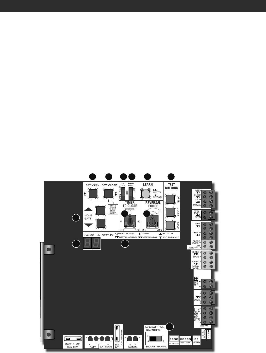
OPERATION
CONTROL BOARD OVERVIEW
1 SET OPEN Button: The SET OPEN button sets the OPEN limit. See Adjust Limits section.
2 SET CLOSE Button: The SET CLOSE button sets the CLOSE limit. See Adjust Limits section.
3 MOVE GATE Buttons: The MOVE GATE buttons will either open or close the gate/door when the operator is in Limit setting mode. See Adjust Limits
section.
4 BATT FAIL:
• When AC power is OFF and battery voltage is critically low the gate/door will latch at a limit until AC power is restored or batteries voltage increases.
• Option select switch set to OPEN forces gate/door to automatically open and then latch at the OPEN limit until AC power is restored or battery
voltage increases.
• Option select switch set to CLOSE forces gate/door to latch at CLOSE limit if at CLOSE limit or on next CLOSE command until AC power restored or
battery voltage increases.
• Constant pressure on a hard command input overrides to open or close the gate/door.
• Critically low battery is less than 23 V.
5 BIPART DELAY Switch: The BIPART DELAY switch is used to select the opening speed. See page 25.
6 LEARN Button: The LEARN button is for programming remote controls and the network.
7 TIMER-TO-CLOSE dial: The TIMER-TO-CLOSE (TTC) dial can be set to automatically close the gate/door after a specified time period. The TTC is fac-
tory set to OFF. If the TTC is set to the OFF position, then the gate/door will remain open until the operator receives another command from a control.
Rotate the TIMER-TO-CLOSE dial to the desired setting. The range is 0 to 180 seconds, 0 seconds is OFF.
NOTE: Any radio command, single button control, or CLOSE command on the control board prior to the TTC expiring will close the gate/door. The TTC
is reset by any signals from the open controls, loops, close edges, and close photoelectric sensors (IR’s).
8 REVERSAL FORCE dial: The REVERSAL FORCE dial adjusts the force. See Force Adjustment section.
9 TEST BUTTONS: The TEST BUTTONS will operate the gate/door (OPEN, STOP and CLOSE).
10 STATUS LEDs: The STATUS LEDs indicate the status of the operator. See Status LED Chart in the Troubleshooting section.
11 DIAGNOSTIC CODE DISPLAY: The diagnostic code display will show the operator type, firmware version, and diagnostic codes. The operator type will
display as "HC" followed by a "24" which indicates the operator type as HCTDCU. The firmware version will show after the operator type, example "1.2".
12
BACKDRIVE
Switch: ALWAYS set to SECURE to enable motor braking. To manually move the gate/door see page 26.
1 2
3
4 5
7 8
9
1011
6
12