Chamberlain Group The 8389 Overhead Door and Gate Operator User Manual 01 37718 indd
Chamberlain Group Inc, The Overhead Door and Gate Operator 01 37718 indd
Contents
- 1. User Manual_20160711_v1 - User Manual pt1 HCTDCU
- 2. User Manual_20160711_v1 - User Manual pt2 HCTDCU
- 3. User Manual_20160711_v1 - User Manual pt3 HCTDCU
- 4. User Manual_20160711_v1 - User Manual pt4 HCTDCU
- 5. User Manual_20160711_v1 - User Manual pt5 HCTDCU
- 6. User Manual_20160711_v1 - User Manual pt6 HCTDCU
- 7. User Manual_20160711_v1 - User Manual pt7 HCTDCU
- 8. User Manual_20160711_v1 - User Manual pt8 HCTDCU
User Manual_20160711_v1 - User Manual pt4 HCTDCU

37
SYMPTOM POSSIBLE CAUSES SOLUTIONS
Operator does not
run and diagnostic
code display not
on
a) No power to control board
b) Open fuse
c) If on battery power only, low or dead batteries
d) Defective control board
a) Check AC and battery power.
b) Check fuses.
c) Charge batteries or replace batteries.
d) Replace defective control board.
Control board
powers up, but
motor does not run
a) Reset switch is stuck
b) Stop button active or jumper not in place
for stop circuit
c) If on battery power only, low or dead batteries
d) Open or Close input active
e) Entrapment Protection Device active
f) Vehicle loop detector or probe active
g) Defective control board
a) Check reset switch.
b) Check Stop button is not “stuck on”, or verify that the stop button is a
normally closed circuit, or put a jumper on the stop circuit.
c) Charges batteries or replace batteries.
d) Check all Open and Close inputs for a “stuck on” input .
e) Check all Entrapment Protection Device inputs for a “stuck on” sensor.
f) Check all vehicle detector inputs for a “stuck on” detector.
g) Replace defective control board.
Gate/door moves,
but cannot set
correct limits
a) Gate/door does not move to a limit
position
b) Gate/door is too difficult to move
c) Limits are set too close
a) Use manual disconnect, manually move gate/door, and ensure gate/door
moves easily limit to limit. Repair gate/door as needed.
b) Gate/door must move easily and freely through its entire range, limit to
limit. Repair gate/door as needed.
c) Ensure the gate/door moves at least one foot (30.5 cm) between the OPEN
limit and the CLOSE limit.
Gate/door does not
fully open or fully
close when setting
limits
a) Gate/door does not move to a limit
position
b) Gate/door is too difficult to move
a) Use manual disconnect, manually move gate/door, and ensure gate/door
moves easily limit to limit. Repair gate/door as needed.
b) Gate/door must move easily and freely through its entire range, limit to
limit. Repair gate/door as needed.
Operator does not
respond to a wired
control/command
(example: Open,
Close, SBC, etc.)
a) Check Open and Close command input LEDs
b) Stop button is active
c) Reset button is stuck
d) If on battery power only, low or dead batteries
e) Entrapment Protection Device active
f) Vehicle loop detector or vehicle probe active
a) Check all Open and Close inputs for a “stuck on” input.
b) Check Stop button is not “stuck on”.
c) Check Reset button.
d) Charge batteries or replace batteries.
e) Check all Entrapment Protection Device inputs for a “stuck on” sensor.
f) Check all vehicle detector inputs for a “stuck on” detector.
Operator does not
respond to a
wireless control or
transmitter
a) Check XMITTER LED when wireless
control is active
b) Stop button is active
c) Reset button is stuck
d) Poor radio reception
a) Activate wireless control and check XMITTER LED is on. Re-learn wireless
control/transmitter to control board. Replace wireless control as needed.
b) Check Stop button is not “stuck on”.
c) Check Reset button.
d) Check if similar wired control operates correctly. Check if wireless controls
works properly when within a few feet of operator. Check operator’s
antenna and antenna wire. Check other wireless controls or devices.
Gate/door stops
during travel and
reverses
immediately
a) Control (Open, Close) becoming active
b) Vehicle loop detector active
c) Low battery voltage
a) Check all Open and Close inputs for an active input.
b) Check all vehicle detector inputs for an active detector.
c) Battery voltage must be 23.0 Vdc or higher. Charge batteries or replace
batteries.
Gate/door opens,
but will not close
with transmitter or
Timer-to-Close
a) Open control active
b) Vehicle loop detector active
c) Loss of AC power with AC FAIL set to
OPEN
d) Low battery with LOW BATT set to OPEN
e Fire Dept input active
f) Timer-to-Close not set
g) Close Entrapment Protection Device active
a) Check all Open inputs for an active input.
b) Check all vehicle detector inputs for an active detector.
c) Check AC power and AC Fail option setting.
d) Check if AC power is available. If no AC power, then running on batteries
and battery voltage must be 23.0 Vdc or higher. Charge batteries or replace
batteries.
e) Check Fire Dept input.
f) Check Timer-to-Close (TTC) setting.
g) Check all Entrapment Protection Device inputs for an active sensor.
Gate/door closes,
but will not open a) Vehicle loop detector active
b) Low battery with LOW BATT option set to
CLOSE
a) Check all vehicle detector inputs for an active detector.
b) Check if AC power is available. If no AC power, then running on batteries
and battery voltage must be 23.0 Vdc or higher. Charge batteries or replace
batteries.
TROUBLESHOOTING CHART
TROUBLESHOOTING

38
SYMPTOM POSSIBLE CAUSES SOLUTIONS
Exit loop activation
does not cause
gate/door to open
a) Exit vehicle detector setup incorrectly
b) Defective Exit loop detector
c) Low battery with LOW BATT option set
to CLOSE
a) Review Exit loop detector settings. Adjust settings as needed.
b) Replace defective Exit loop detector.
c) Check if AC power is available. If no AC power, then running on batteries and
battery voltage must be 23.0 Vdc or higher. Charge batteries or replace
batteries.
Interrupt loop does
not cause gate/door
to stop and reverse
a) Vehicle detector setup incorrectly
b) Defective vehicle loop detector
c) Anti-tail set to ON
a) Review Interrupt loop detector settings. Adjust settings as needed.
b) Replace defective Interrupt loop detector.
c) Set anti-tail to OFF.
Shadow loop does
not keep gate/door
at open limit
a) Vehicle detector setup incorrectly
b) Defective vehicle loop detector
a) Review Shadow loop detector settings. Adjust settings as needed.
b) Replace defective Shadow loop detector.
Obstruction in gate/
door's path does
not cause gate/door
to stop and reverse
a) Force adjustment needed a) Refer to the Adjustment section to conduct the obstruction test and perform
the proper force adjustment that is needed.
Photoelectric
sensor does not
stop or reverse
gate/door
a) Incorrect photoelectric sensor wiring
b) Defective photoelectric sensor
a) Check photoelectric sensor wiring. Retest that obstructing photoelectric
sensor causes moving gate/door to stop, and may reverse direction.
b) Replace defective photoelectric sensor. Retest that obstructing photoelectric
sensor causes moving gate/door to stop, and may reverse direction.
Edge Sensor does
not stop or reverse
gate/door
a) Incorrect edge sensor wiring
b) Defective edge sensor
a) Check edge sensor wiring. Retest that activating edge sensor causes moving
gate/door to stop and reverse direction.
b) Replace defective edge sensor. Retest that activating edge sensor causes
moving gate/door to stop and reverse direction.
Alarm sounds for 5
minutes or alarm
sounds with a
command
a) Double entrapment occurred (two
obstructions within a single activation) a) Check for cause of entrapment (obstruction) detection and correct. Press the
reset button to shut off alarm and reset the operator.
Alarm beeps three
times with a
command
a) Low battery a) Check if AC power is available. If no AC power, then running on batteries and
battery voltage must be 23.0 Vdc or higher. Charge batteries or replace
batteries.
Alarm beeps when
running a) Expansion board setting
b) Constant pressure to open or close is
given
a) Pre-warning is set to "ON".
b) Constant pressure to open or closed is given.
Expansion board
function not
controlling
gate/door
a) Defective main board to expansion
board wiring
b) Incorrect input wiring to expansion
board
c) Defective expansion board or defective
main board
a) Check main board to expansion board wiring. If required, replace wire cable.
b) Check wiring to all inputs on expansion board.
c) Replace defective expansion board or defective main board.
TROUBLESHOOTING
TROUBLESHOOTING CHART continued...

39
SYMPTOM POSSIBLE CAUSES SOLUTIONS
Switched (SW) Accessory
power remaining on a) In limit setup mode a) Learn the limits.
Accessories connected to
Switch (SW) Accessory
power not working correctly,
turning off, or resetting
a) Normal behavior a) Move accessory to accessory power "ON".
Accessories connected to
Accessory power not
working correctly, turning
off, or resetting
a) Accessory power protector active
b) Defective control board
a) Disconnect all accessory powered devices and measure accessory
power voltage (should be 23 – 30 Vdc). If voltage is correct, connect
accessories one at a time, measuring accessory voltage after every
new connection.
b) Replace defective control board.
Quick Close not working
correctly a) Quick Close setting incorrect
b) Interrupt loop detector
c) Defective Expansion board
a) Check that Quick Close setting is ON.
b) Check operation of Interrupt Loop detector.
c) Replace defective Expansion board.
Anti-Tailgating not working
correctly a) Anti-Tail setting incorrect
b) Interrupt loop detector
c) Defective Expansion board
a) Check that Anti-Tail setting is ON.
b) Check operation of Interrupt Loop detector.
c) Replace defective Expansion board.
AUX Relay not working
correctly a) AUX Relay setting incorrect
b) AUX Relay wiring incorrect
c) Defective Expansion board
a) Check AUX Relay switches settings.
b) Check that wiring is connected to either N.O. and COM or to N.C.
and COM.
c) Set AUX Relay to another setting and test. Replace defective
expansion board.
TROUBLESHOOTING
TROUBLESHOOTING CHART continued...
40
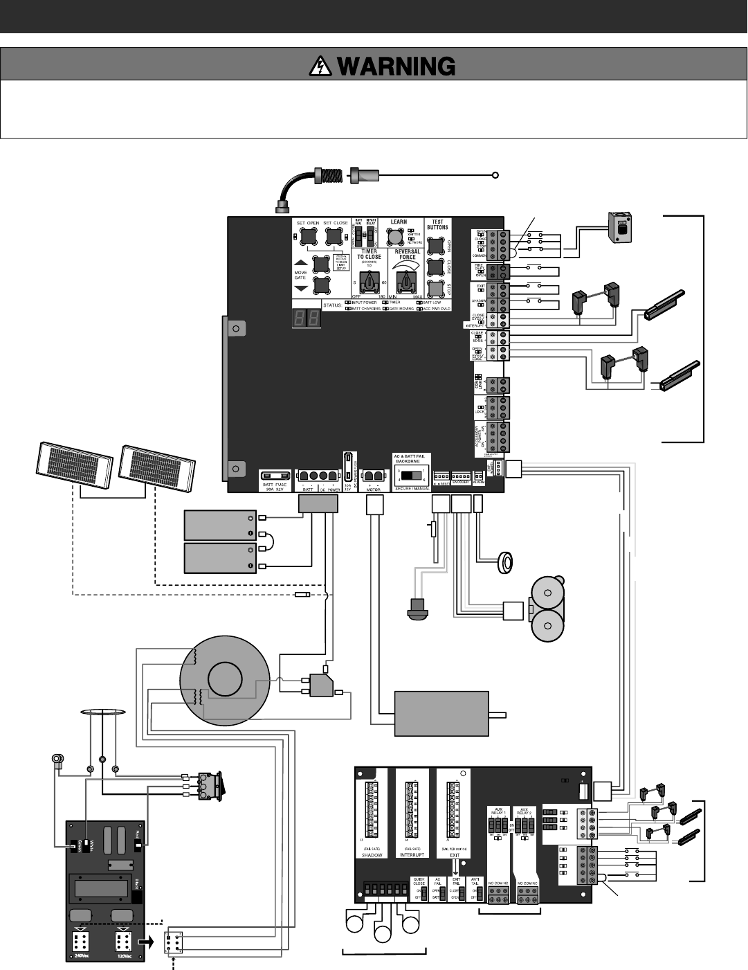
WIRING DIAGRAM
DIAGNOSTICS
+
-
+
-
+
+
-
+
-
+
-
+
-
+
-
+
+
-
+
-
+
-
-
-
SHADOW INTERUPT EXIT
SBC
OPN
CLS
STP
COM
EYE
ONLY
EYE/
EDGE
EYE/
EDGE
COM
1
2
3
OPEN
CLOSE
TO MAIN
BOARD
POWER
4321
4321
321
+
-
+
+
Coaxial Antenna Cable
Two 12V Solar Panels in Series (Optional)
12V 7AH Battery
12V 7AH Battery
Transformer 375 VA, 24V, 120V
Bridge Rectifier
EXPANSION BOARD
Black
Black
Purple
Brown
Blue
Gray
Orange
Orange
Red
Red
Black
Red
CONTROL BOARD
Piezo Alarm
APS Encoder
1/2 HP 24 Vdc Motor
Product ID
White
White
Black
Red
Black
Red
Red
Reset Button
Field Wiring
Blocking Diode
Antenna
Photoelectric Sensors
and Edge Sensors
Field Wiring Field Wiring
Field Wiring
Wire Loop
Wire Loop
Wire Loop
N.C.
N.C.
Jumper
Jumper
Yellow
Blue
Black
Red
External Reset
Button
Power Wiring Connector
Power Wiring Sockets
(120 Vac factory default)
EMI BOARD
Input Power
Connection
HOT
NEUTRAL
GROUND
Black
Green
Green
White
White
Red
Piggy Back
AC Power
Switch
To protect against fire and electrocution:
• DISCONNECT power (AC or solar and battery) BEFORE installing or
servicing operator.
For continued protection against fire:
• Replace ONLY with fuse of same type and rating.
41
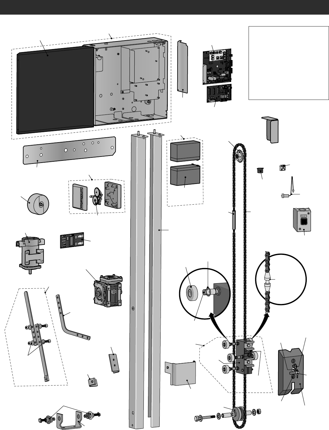
REPAIR PARTS
Idler Sprocket
K75-50149
Mounting Plate
K10-37641
Operator Cover
K10-37598
Output Sprocket
K15-41B17LKGH
Chain Guard
K10-37955
Trolley Body
K75-50137
Rail
8' (2.4 m) - HCT08
10' (3.1 m) - HCT10
12' (3.7 m) -HCT12
Trolley Wheel Shaft
K11-50136
Trolley Body
Assembly
K75-50147
Retaining
Ring Clip
K87-E-050
Chain Coupling
Release
K07-50215
Trolley Wheels
K13-50141
Arm Bracket
K09-50152
Alternative
Door Mounting
Bracket
10-10204
Arm Bushing
K77-50153
Rubber Isolator
K75-50150
Arm Assembly
K75-50146
Header Bracket
K10-50154
Idler Sprocket Cover
K10-50151
Plastic Plug
K80-20078 Trolley Cover
K09-50756
Release Ring
K80-50145
Key Release
K80-50142
Alarm
K94-36411
Expansion Board
K1D8387-1CC
Gear Reducer (28:1)
K32-37560-3
Antenna
K77-36541
External
Reset Button
UNISW
Main Control Board
K1D8389-1CC
Battery
Access Door
K10-37595
Toroid Transformer
K204C0211
Bridge Rectifier
K52C0481
APS Encoder, 24V
K76-34697
Key
K80-50295
Two 7AH batteries
K74-30762
Single Battery
7AH, 12 Vdc
29-NP712
Trolley
Latch
K75-50138
Turn Buckle
K75-50132 Chain #41
(10' [3.1 m] per box)
19-41240D
Motor
K76-36398
Chassis and Cover
K75-38058
EMI Board
120V/240V
K1D7078
APE Assembly with plastic tray
K1A6408
Curved
Door Arm
K10-10203
NOT SHOWN
K94-37205 Battery Harness (for 7AH
batteries)
K94-34778 Board to board wire
harness (main board to
expansion board)
K94-37806 Reset switch with ID
resistor
K40-38471 U.L. Warning Sign
K94-36891 7AH Solar Battery
Harness
42
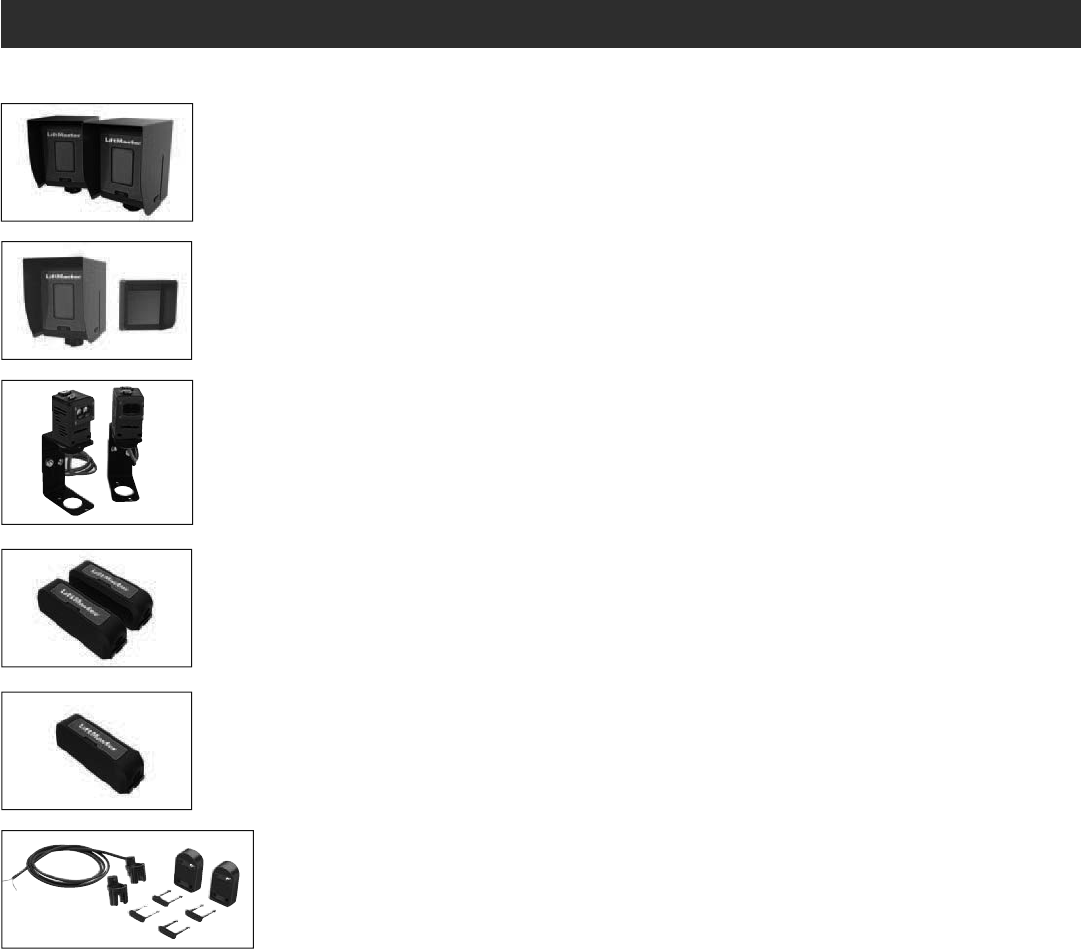
ACCESSORIES
ENTRAPMENT PROTECTION
LIFTMASTER MONITORED THROUGH
BEAM PHOTOELECTRIC SENSOR
Model LMTBU
LIFTMASTER MONITORED RETRO-
REFLECTIVE PHOTOELECTRIC SENSOR
Model LMRRU and CPS-RPEN4GM
LIFTMASTER COMMERCIAL PROTECTOR
SYSTEM®
Models CPS-UN4 and CPSUN4G
LIFTMASTER MONITORED WIRELESS
EDGE KIT (TRANSMITTER AND RECEIVER)
Model LMWEKITU
LIFTMASTER MONITORED WIRELESS
EDGE TRANSMITTER
Model LMWETXU
MONITORED RESISTIVE STANDARD
EDGE - LARGE PROFILE
82 foot roll
Model L50
LARGE PROFILE END CAPS
10 pairs
Model L50E
PLASTIC CHANNEL
8 foot (2.4 m) for both Small and Large Edge Profiles. Pack of 10
Model L50CHP
ALUMINUM CHANNEL
10 foot (3.1 m) for both Small and Large Edge Profiles. Pack of 8
Model L50CHAL
EDGE CUTTING TOOL
Model ETOOL
WRAPAROUND SQUARE MONITORED EDGE - COMING SOON!
4 foot (1.2 m)
Model WS4
WRAPAROUND SQUARE MONITORED EDGE - COMING SOON!
5 foot (1.5 m)
Model WS5
WRAPAROUND SQUARE MONITORED EDGE - COMING SOON!
6 foot (1.8 m)
Model WS6
WRAPAROUND ROUND MONITORED EDGE
4 foot (1.2 m)
Model WR4
WRAPAROUND ROUND MONITORED EDGE
5 foot (1.5 m)
Model WR5
WRAPAROUND ROUND MONITORED EDGE
6 foot (1.8 m)
Model WR6
LARGE PROFILE EDGE IN ALUMINUM CHANNEL
4 foot (1.2 m)
Model L504AL
LARGE PROFILE EDGE IN ALUMINUM CHANNEL
5 foot (1.5 m)
Model L505AL
LARGE PROFILE EDGE IN ALUMINUM CHANNEL
6 foot (1.8 m)
Model L506AL
SMALL PROFILE EDGE IN ALUMINUM CHANNEL
4 foot (1.2 m)
Model S504AL
SMALL PROFILE EDGE IN ALUMINUM CHANNEL
5 foot (1.5 m)
Model S505AL
SMALL PROFILE EDGE IN ALUMINUM CHANNEL
6 foot (1.8 m)
Model S506AL
43
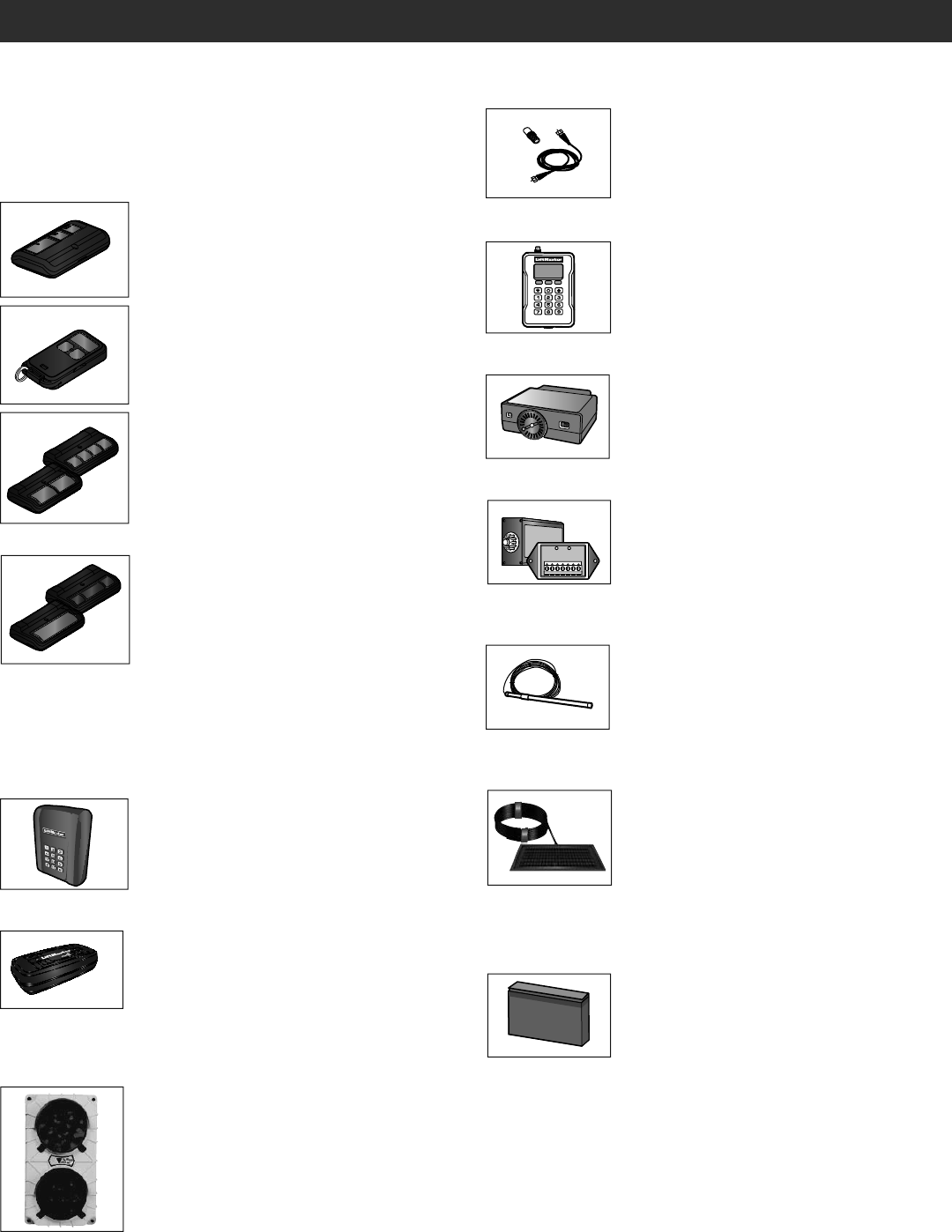
ACCESSORIES
REMOTE ANTENNA EXTENSION KIT
The remote antenna extension kit allows the
antenna to be remotely installed.
Model 86LM
COMMERCIAL ACCESS CONTROL RECEIVER
Access control receiver for up to 1,000 devices
(any combination of remote controls and wireless
keyless entries).
Model STAR1000
PLUG-IN LOOP DETECTOR
Conveniently plugs into existing control board.
Model LOOPDETLM
LOOP DETECTOR
Low power loop detectors mounted and wired
separately inside control box. LiftMaster low power
accessory.
Model LD7LP
VEHICLE SENSING PROBE
The vehicle sensing probe is buried in the ground
and can detect a car as it approaches and will then
open the gate.
Model CP3
SOLAR PANEL KIT
This kit is to replace or add a solar panel to the
operator application. 60W maximum for 24 Vdc
operators and 30W maximum for 12 Vdc
operators.
Models SP10W12V (10 Watt, 12V) and SP20W12V
(20 Watt, 12V)
MISCELLANEOUS
MISCELLANEOUS
LIFTMASTER® INTERNET GATEWAY
Internet enabled accessory which connects to the
computer and allows you to monitor and control
gate/door operators and lighting accessories
enabled by MyQ® technology.
Model 828LM
7AH BATTERIES
Standard 7 AMP-Hour Battery, 12 Vdc, to replace
original battery provided with operator. Reuse
existing harnesses.
Models 29-NP712 (1) and K74-30762 (2)
REMOTE CONTROLS
LiftMaster offers a variety of LiftMaster remote controls to satisfy your
application needs. Single-button to 4-button, visor or key chain. The
following remote controls are compatible with operators manufactured by
LiftMaster after 1993. Contact your authorized LiftMaster dealer for
additional details and options.
3-BUTTON REMOTE CONTROL
The 3-button remote control can be programmed to
control the operator. Includes visor clip.
Model 893MAX
3-BUTTON MINI-REMOTE CONTROL
The 3-button remote control can be programmed to
control the operator. Includes key ring and
fastening strip.
Model 890MAX
SECURITY+ 2.0® LEARNING REMOTE CONTROLS
One button can control a gate/door operator and
the other(s) can control garage door(s). It can also
be programmed to Security+® or Security+ 2.0®
code format.
Models 892LT and 894LT
UNIVERSAL SINGLE AND 3-BUTTON REMOTE
CONTROLS
Ideal for applications requiring a large number of
remote controls.
Models 811LM and 813LM
WIRELESS COMMERCIAL KEYPAD
Durable wireless keypad with blue LED backlight
metal keypad, zinc-alloy metal front cover and 5
year 9V Lithium battery. Security+ 2.0® compatible.
Model KPW250
RED/GREEN TRAFFIC LIGHT:
Indicates when a gate/door or door reaches the
open position. Provides assurance of safe entering
and exiting of the facility, reducing the potential
for costly accidents.
Model RGL24LY

5 YEAR COMMERCIAL LIMITED WARRANTY
LiftMaster (“Seller”) warrants to the first purchaser of this product, for the structure in which this product is originally installed, that it is free from
defect in materials and/or workmanship for a period of 5 year commercial from the date of purchase [and that the HCTDCU is free from defect in
materials and/or workmanship for a period of 5 year commercial from the date of purchase]. The proper operation of this product is dependent on
your compliance with the instructions regarding installation, operation, maintenance and testing. Failure to comply strictly with those instructions will
void this limited warranty in its entirety.
If, during the limited warranty period, this product appears to contain a defect covered by this limited warranty, call 1-800-528-2806, toll free, before
dismantling this product. Then send this product, pre-paid and insured, to our service center for warranty repair. You will be advised of shipping
instructions when you call. Please include a brief description of the problem and a dated proof-of-purchase receipt with any product returned for
warranty repair. Products returned to Seller for warranty repair, which upon receipt by Seller are confirmed to be defective and covered by this limited
warranty, will be repaired or replaced (at Seller’s sole option) at no cost to you and returned pre-paid. Defective parts will be repaired or replaced with
new or factory-rebuilt parts at Seller’s sole option.
ALL IMPLIED WARRANTIES FOR THE PRODUCT, INCLUDING BUT NOT LIMITED TO ANY IMPLIED WARRANTIES OF MERCHANTABILITY AND
FITNESS FOR A PARTICULAR PURPOSE, ARE LIMITED IN DURATION TO THE 5 YEAR COMMERCIAL LIMITED WARRANTY PERIOD SET FORTH
ABOVE [EXCEPT THE IMPLIED WARRANTIES WITH RESPECT TO THE HCTDCU, WHICH ARE LIMITED IN DURATION TO THE 5 YEAR COMMERCIAL
LIMITED WARRANTY PERIOD FOR THE HCTDCU], AND NO IMPLIED WARRANTIES WILL EXIST OR APPLY AFTER SUCH PERIOD. Some states do
not allow limitations on how long an implied warranty lasts, so the above limitation may not apply to you. THIS LIMITED WARRANTY DOES NOT
COVER NON-DEFECT DAMAGE, DAMAGE CAUSED BY IMPROPER INSTALLATION, OPERATION OR CARE (INCLUDING, BUT NOT LIMITED TO
ABUSE, MISUSE, FAILURE TO PROVIDE REASONABLE AND NECESSARY MAINTENANCE, UNAUTHORIZED REPAIRS OR ANY ALTERATIONS TO
THIS PRODUCT), LABOR CHARGES FOR REINSTALLING A REPAIRED OR REPLACED UNIT, OR REPLACEMENT OF BATTERIES.
THIS LIMITED WARRANTY DOES NOT COVER ANY PROBLEMS WITH, OR RELATING TO, THE GATE/DOOR OR GATE/DOOR HARDWARE,
INCLUDING BUT NOT LIMITED TO THE GATE/DOOR SPRINGS, GATE/DOOR ROLLERS, GATE/DOOR ALIGNMENT OR HINGES. THIS LIMITED
WARRANTY ALSO DOES NOT COVER ANY PROBLEMS CAUSED BY INTERFERENCE. ANY SERVICE CALL THAT DETERMINES THE PROBLEM HAS
BEEN CAUSED BY ANY OF THESE ITEMS COULD RESULT IN A FEE TO YOU.
UNDER NO CIRCUMSTANCES SHALL SELLER BE LIABLE FOR CONSEQUENTIAL, INCIDENTAL OR SPECIAL DAMAGES ARISING IN CONNECTION
WITH USE, OR INABILITY TO USE, THIS PRODUCT. IN NO EVENT SHALL SELLER’S LIABILITY FOR BREACH OF WARRANTY, BREACH OF
CONTRACT, NEGLIGENCE OR STRICT LIABILITY EXCEED THE COST OF THE PRODUCT COVERED HEREBY. NO PERSON IS AUTHORIZED TO
ASSUME FOR US ANY OTHER LIABILITY IN CONNECTION WITH THE SALE OF THIS PRODUCT.
Some states do not allow the exclusion or limitation of consequential, incidental or special damages, so the above limitation or exclusion may not
apply to you. This limited warranty gives you specific legal rights, and you may also have other rights which vary from state to state.
WARRANTY
Wi-Fi® is a registered trademark of Wi-Fi Alliance
01-37718 © 2016, LiftMaster – All Rights Reserved
845 Larch Avenue
Elmhurst, Illinois 60126-1196
LiftMaster.com
ACTIONNEUR DE PORTE ET BARRIÈRE
BASCULANTES COMMERCIALES 24 V C. C.
POUR TRAFIC INTENSE
AVEC BATTERIE DE SECOURS
Modèle HCTDCU
MANUEL D’INSTALLATION
LiftMaster
845 Larch Avenue
Elmhurst, IL 60126-1196
• CE PRODUIT DOIT ÊTRE EXCLUSIVEMENT INSTALLÉ ET
ENTRETENU PAR UN TECHNICIEN DÛMENT FORMÉ.
• Ce modèle est prévu pour être utilisé UNIQUEMENT sur les
barrières de passage véhiculaire ou les portes commerciales et
n’est pas prévu sur les barrières destinées au passage des piétons.
• Installer l’actionneur à au moins 2,4 m (8 pi) au-dessus du sol.
• Ce modèle est prévu pour un usage dans les applications de
barrière véhiculaire à chariot ou de porte commerciale de classes
II, III et IV.
• Aller sur LiftMaster.com pour localiser le détaillant-installateur le
plus proche.
• Cet actionneur de barrière/porte est compatible avec les
accessoires MyQ® et Security+ 2.0®.
Enregistrez votre actionneur pour
recevoir des mises à jour et des offres
de LiftMaster
Prenez une photo de l’icône d’appareil-
photo, y compris les points ( ).
Envoyez la photo par message textuel
à 71403 (É.-U.) ou allez à
www.liftmaster.photo (mondial)
HCTDCU
Moteur
HCT08
Rail de 2,4 m (8 pi)
HCT10
Rail de 3,1 m (10 pi)
HCT12
Rail de 3,7 m (12 pi)
PHOTOREGISTER
SM
LM-HCTROLLEY

2
SÉCURITÉ
REVUE DES SYMBOLES DE SÉCURITÉ ET DES
MOTS DE SIGNALEMENT
Lorsque vous verrez ces symboles de sécurité et ces mots de signalement sur
les pages suivantes, ils vous aviseront de la possibilité de blessures graves ou
de mort si vous ne vous conformez pas aux avertissements qui les
accompagnent. Le danger peut être de source mécanique ou provenir d'un choc
électrique. Lisez attentivement les avertissements.
Lorsque vous verrez ce mot de signalement sur les pages suivantes, il vous
alertera de la possibilité de dommage à la barrière/porte et/ou à l'actionneur de
barrière/porte si vous ne vous conformez pas aux avertissements
l'accompagnant. Lisez-les attentivement.
REMARQUE IMPORTANTE :
• AVANT d'essayer d'installer, de faire fonctionner ou d'assurer l'entretien de
l'actionneur, vous devez lire et comprendre intégralement ce manuel et
appliquer toutes les instructions de sécurité.
• L’ouvre-porte est conçu pour être installé uniquement sur une barrière/porte
bien équilibrée. Vérifier que la barrière/porte est correctement équilibrée avant
l’installation.
• NE PAS tenter de réparer ou d’entretenir votre actionneur à moins d’être un
technicien d’entretien agréé.
TABLE DES MATIÈRES
SÉCURITÉ 2
REVUE DES SYMBOLES DE SÉCURITÉ ET DES MOTS
DE SIGNALEMENT ................................................................................2
CLASSE D’UTILISATION ........................................................................3
EXIGENCES DE PROTECTION CONTRE LE PIÉGEAGE UL325 ...............3
INFORMATION SUR L’INSTALLATION SÉCURITAIRE ...........................4
INFORMATIONS DE CONSTRUCTION DE BARRIÈRE ............................5
INTRODUCTION 6
CONTENU DE L'EMBALLAGE .................................................................6
SPÉCIFICATIONS DE L'ACTIONNEUR ....................................................7
APERÇU D’UNE INSTALLATION TYPIQUE .............................................8
INSTALLATION 9
RENSEIGNEMENTS DE SÉCURITÉ IMPORTANTS .................................9
RACCORDER LE RAIL À L'ACTIONNEUR ............................................10
INSTALLER LE BOUCHON DE MISE À L'AIR LIBRE ............................11
DÉTERMINER L'EMPLACEMENT DE L'ACTIONNEUR ..........................11
MONTER L'ACTIONNEUR ....................................................................12
INSTALLER LE DISPOSITIF DE PROTECTION CONTRE
LE PIÉGEAGE .......................................................................................13
CÂBLAGE 15
CÂBLAGE ÉLECTRIQUE .......................................................................15
CONNECTER LES BATTERIES ..............................................................16
AJUSTEMENT 17
RÉGLAGES DE COURSE ET DE FORCE ................................................17
ESSAI D’OBSTRUCTION ......................................................................18
PRÉSENTATION DE L’ACTIONNEUR 19
PROGRAMMATION 20
TÉLÉCOMMANDES (NON FOURNIES) .................................................20
PASSERELLE INTERNET LIFTMASTER (NON FOURNIES) ...................21
EFFACEMENT DE TOUS LES CODES ...................................................21
EFFACEMENT DES LIMITES .................................................................21
RETRAIT ET EFFACEMENT DES DISPOSITIFS SURVEILLÉS DE
PROTECTION CONTRE LE PIÉGEAGE ..................................................21
RÉGLAGE DE LIMITE DE COURSE AVEC UNE TÉLÉCOMMANDE ........22
FONCTIONNEMENT 23
EXEMPLES DE CONFIGURATIONS D’ACTIONNEUR
DE BARRIÈRE/PORTE ..........................................................................23
VUE D’ENSEMBLE DE LA CARTE DE CONTRÔLE ................................24
INTERRUPTEUR DE RÉINITIALISATION ..............................................25
ALARME DE L'ACTIONNEUR ...............................................................25
VITESSE D’OUVERTURE RÉGLABLE ...................................................25
TÉLÉCOMMANDE.................................................................................25
DÉBRANCHEMENT MANUEL ...............................................................26
CÂBLAGE DES ACCESSOIRES 27
DISPOSITIFS DE COMMANDE EXTÉRIEURS .......................................27
BOUTON DE RÉINITIALISATION EXTERNE ..........................................27
CÂBLAGE DIVERS ................................................................................28
TABLEAU D'EXTENSION 29
PRÉSENTATION DU TABLEAU D'EXTENSION .....................................29
RELAIS AUXILIAIRES ..........................................................................30
CÂBLAGE DES ACCESSOIRES AU TABLEAU D'EXTENSION ................31
ENTRETIEN 32
IMPORTANTES INFORMATIONS DE SÉCURITÉ ..................................32
TABLEAU D'ENTRETIEN ......................................................................32
PILES ................................................................................................... 32
DÉPANNAGE 33
CODES DE DIAGNOSTIC ......................................................................33
DEL DE LA CARTE DE CONTRÔLE .......................................................36
TABLEAU DE DÉPANNAGE ..................................................................37
SCHÉMA DE CÂBLAGE 40
PIÈCES DÉTACHÉES 41
ACCESSOIRES 42
GARANTIE 44
MÉCANIQUE
ÉLECTRIQUE
ATTENTION
AVERTISSEMENT
AVERTISSEMENT
AVERTISSEMENT
ATTENTION
AVERTISSEMENT
AVERTISSEMENT
AVERTISSEMENT
ATTENTION
AVERTISSEMENT
AVERTISSEMENT
AVERTISSEMENT
3
Les deux moyens de protection contre le piégeage ne doivent pas
être du même type. L’utilisation d’un seul dispositif pour couvrir les
directions d’ouverture et de fermeture est conforme à l’exigence;
toutefois, un seul dispositif n’est pas exigé pour couvrir les deux
directions. Cet actionneur est fourni avec un dispositif de typeA.
L’installateur est tenu d’installer des dispositifs supplémentaires de
protection contre le piégeage dans chaque zone de piégeage.
ACTIONNEUR À COULISSEMENT HORIZONTAL ET
ACTIONNEUR PIVOTANT
TYPES DE DISPOSITIFS DE PROTECTION CONTRE LE PIÉGEAGE DE
L’ACTIONNEUR DE PORTAIL
Type A Système de protection contre le piégeage inhérent
(intégré à l’actionneur)
Type B1 Capteurs sans contact comme des capteurs
photoélectriques
Type B2 Capteurs à contacts comme des contacts de chant de porte
SÉCURITÉ
EXIGENCES DE PROTECTION CONTRE LE PIÉGEAGE UL325
Cet actionneur de barrière véhiculaire/porte doit être installé avec au moins deux dispositifs indépendants de protection contre le piégeage, comme
précisé dans le tableau ci-dessous.
Pour réduire le risque de BLESSURES GRAVES, voire MORTELLES:
• LIRE ET OBSERVER TOUTES LES INSTRUCTIONS.
• Ne JAMAIS laisser un enfant faire fonctionner ou jouer avec les
commandes d’une barrière ou d’une porte.
• Garder TOUJOURS les personnes et les objets à l’écart de la
barrière/porte. NE JAMAIS LAISSER UNE PERSONNE TRAVERSER
DANS LA TRAJECTOIRE DE LA BARRIÈRE/PORTE EN MOUVEMENT.
• Tester l’actionneur de barrière/porte tous les mois. La barrière/porte
DOIT inverser sa course au contact d’un objet rigide ou lorsqu’un
objet active les capteurs sans contact. Après avoir réglé la résistance
ou la limite de la course, tester de nouveau l’actionneur de barrière/
porte. Le manquement à régler l’actionneur correctement peut
augmenter le risque de BLESSURES GRAVES voire MORTELLES.
• Se servir de la poignée de déclenchement d’urgence UNIQUEMENT
lorsque la barrière/porte est fermée. Faire preuve de prudence
lorsque cette poignée est utilisée alors que la barrière/porte est
ouverte. Des ressorts mous ou brisés peuvent causer la chute rapide
de la barrière/porte et causer des BLESSURES GRAVES, voire
MORTELLES.
• GARDER LES BARRIÈRES OU PORTES EN BON ÉTAT ET BIEN
ÉQUILIBRÉES. Lire le manuel du propriétaire publié par le fabricant
de la barrière/porte. Une barrière/porte fonctionnant mal ou qui est
mal équilibrée peut causer des BLESSURES GRAVES, voire
MORTELLES. Demander à un technicien de service compétent de
réparer la quincaillerie de la porte ou de la barrière. Demander à un
technicien formé en systèmes de barrière/porte de réparer les câbles,
ensembles de ressorts et autres éléments de la quincaillerie.
• L’entrée est prévue UNIQUEMENT pour les véhicules. Les piétons
DOIVENT utiliser une entrée distincte.
• CONSERVER CES INSTRUCTIONS.
ATTENTION
AVERTISSEMENT
AVERTISSEMENT
AVERTISSEMENT
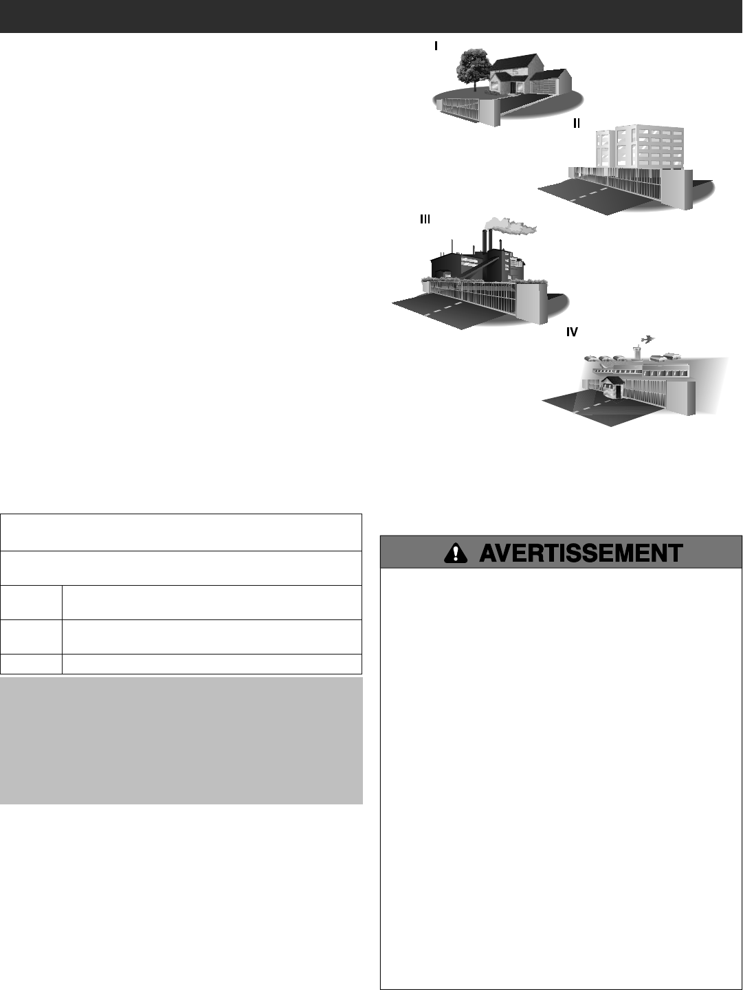
CLASSE D’UTILISATION
RENSEIGNEMENTS DE SÉCURITÉ IMPORTANTS
CLASSE 1 – ACTIONNEUR DE BARRIÈRE
VÉHICULAIRE RÉSIDENTIEL
Un actionneur (ou système) de portail pour véhicules dont l’usage est prévu pour
les garages ou zones de stationnement associés à une résidence d’une à quatre
familles.
CLASSE II – ACTIONNEUR DE BARRIÈRE
VÉHICULAIRE COMMERCIAL/D'ACCÈS GÉNÉRAL
Un actionneur (ou système) de barrière véhiculaire conçu pour utilisation dans un
emplacement commercial ou un édifice comme une unité d'habitation
multifamiliale (cinq logements individuels ou plus), un hôtel, un garage, un
magasin de détail ou autre édifice desservant le grand public.
CLASSE III - MODULE OPÉRATEUR DE PORTAIL
D'ACCÈS DE VÉHICULES DE TYPE INDUSTRIEL OU
LIMITÉ
Un actionneur (ou système) de portail d’accès de véhicules dont l’usage est prévu
dans un site industriel, un bâtiment comme une usine, une aire de chargement ou
tout autre emplacement non réservé au grand public.
CLASSE IV - MODULE OPÉRATEUR DE PORTAIL
D'ACCÈS RESTREINT DE VÉHICULES
Un module opérateur (ou système) de portail d'accès de véhicules destiné à être
utilisé dans un lieu ou un bâtiment industriel protégé comme une zone de sécurité
d'aéroport ou tout autre lieu dont l'accès est interdit au grand public et où le
personnel de sécurité empêche tout accès non autorisé.

4
INFORMATION SUR L’INSTALLATION SÉCURITAIRE
SÉCURITÉ
1. Les systèmes de barrières véhiculaires fournissent commodité et
sécurité. Les systèmes de barrières se composent de plusieurs
pièces. L'actionneur de barrière n'est qu'une des composantes.
Chaque système de barrières est conçu spécifiquement pour une
application individuelle.
2. Les concepteurs, installateurs et utilisateurs des systèmes de
barrières doivent tenir compte des dangers possibles associés à
chaque installation individuelle. Une conception, installation ou
entretien inapproprié peuvent engendrer des risques pour les
utilisateurs ainsi que les passants. La conception ainsi que
l'installation des systèmes de barrières doivent réduire l'exposition
du public à des risques potentiels.
3. Un actionneur de barrière peut générer de hauts niveaux de
résistance lors de son fonctionnement en tant que composant d'un
système de barrières. Des caractéristiques de sécurité doivent donc
être incorporées lors de chaque conception. Les caractéristiques en
sécurité comportent :
• Arêtes de barrière • Gardes pour rouleaux exposés
• Capteurs photoélectriques • Mailles d'écrans
• Poteaux verticaux • Panneaux indicateurs pour
instructions et avertissements
4. Installer l'actionneur de barrière uniquement lorsque :
a. L'actionneur est approprié pour le type de construction ainsi que
pour la classification d'utilisation de la barrière.
b. Toutes les ouvertures d'une barrière horizontale coulissante sont
protégées ou blindées à partir d'une distance minimum de 6 pi
(1,8 m) au-dessus du sol de la partie inférieure de la barrière
pour qu'une sphère d'un diamètre de 2-1/4 po (6 cm) ne puisse
passer par toute ouverture située sur la barrière et sur la portion
de la clôture adjacente que la barrière recouvre lorsqu'en position
ouverte.
c. Tous les bouts retreints exposés sont dissimulés ou protégés et
qu'un garde pour les rouleaux exposés est mis en place.
5. L'actionneur est prévu pour installation uniquement sur les barrières
utilisées par des véhicules. Les piétons doivent avoir une ouverture
d'accès séparée. L'ouverture pour piétons doit être conçue de façon
telle à promouvoir son utilisation par les piétons. Mettez la barrière
en position telle que les individus n'entrent pas en contact avec la
totalité du chemin de déplacement de la barrière véhiculaire.
6. La barrière doit être installée dans un emplacement où il y a
suffisamment de dégagement entre la barrière et des structures
adjacentes lors de son ouverture et fermeture pour ainsi réduire le
risque de piégeages. Les barrières à pivotement ne doivent pas
ouvrir sur des emplacements à accès publics.
7. La barrière doit être installée correctement et opérer librement dans
les deux sens avant l'installation de l'actionneur de barrière.
8. Les contrôles prévus pour activation par l'utilisateur doivent être
situés à une distance éloignée d'au moins 6 pieds (1,8 m) de toute
partie mobile de la barrière et de plus doivent être placés de façon à
empêcher l'utilisateur d'opérer les contrôles en passant par
dessous, en dessous, autour ou au travers de la barrière. Les
contrôles dont l'accès est d'un abord facile doivent incorporer une
fonction de sécurité pour empêcher une utilisation non autorisée.
Exception: Les commandes d’accès de secours accessibles
uniquement au personnel autorisé (p. ex., police, pompiers) peuvent
être placées à n’importe quel endroit qui se trouve en visibilité
directe du portail.
9. La fonction d'arrêt et/ou réinitialisation (si fournie séparément) doit
être située dans la ligne visuelle de la barrière. L'activation du
contrôle de réinitialisation ne doit pas entraîner le démarrage de
l'actionneur.
10. Un minimum de deux (2) PANNEAUX D'AVERTISSEMENT sera
installé de chaque côté de la barrière, un sur un côté et un sur
l'autre, et ils doivent être clairement visibles.
11. Pour un actionneur de barrière qui utilise un capteur sans contact :
a. Consultez le manuel de l’actionneur en ce qui concerne
l'emplacement pour le capteur sans contact pour chaque type
d'application. Voir la section Installer le dispositif de protection
contre le piégeage.
b. Des précautions seront exercées pour réduire le risque de
déclenchement adverse, comme exemple, un véhicule qui
déclenche le capteur lorsque la barrière est toujours en
déplacement.
c. Un ou plusieurs capteurs sans contact seront situés là où le
risque de piégeage ou d'obstruction existe, tel le périmètre de la
portée d'une barrière ou d'un garde en déplacement.
12. Pour un actionneur de barrière qui utilise un capteur à contact tel un
capteur d'arête :
a. Un ou plusieurs capteurs seront situés là où le risque de piégeage
ou d'obstruction existe, tel le bord d'attaque, le bord de fuite et
seront montés sur poteau à l'intérieur ainsi qu'à l'extérieur d'une
barrière véhiculaire coulissante horizontale.
b. Un capteur de contact à raccordement fixe ainsi que son câblage
seront situés de façon telle que la communication entre le capteur
et l'actionneur de barrière ne subisse pas de dommages
mécaniques.
c. Un capteur sans fil à contact tel un capteur qui transmet des
signaux de fréquences radio (RF) à l'actionneur de barrière pour
raison de protection contre le piégeage sera situé là où la
transmission des signaux n'est pas obstruée ni entravée par des
bâtiments, un paysage naturel ou d'autres obstructions similaires.
Un capteur sans fil fonctionnera comme prévu selon les
conditions d'utilisation finales.
d. Un ou plusieurs capteurs seront situés à l'intérieur et à l'extérieur
du bord d'attaque d'une barrière à pivotement. De plus, si le bord
inférieur d'une barrière à pivotement est à plus de 6 po (15,2 cm)
au-dessus du sol en tout point de l'arc de déplacement, un ou
plusieurs capteurs seront situés sur le bord inférieur.
e. Un ou plusieurs capteurs seront situés sur le bord inférieur d'une
barrière verticale (bras).
f. Un ou plusieurs capteurs seront situés sur le bord inférieur d'une
barrière véhiculaire à porte levante.
g. Un ou plusieurs capteurs de contact doivent être situés au point
de pincement d’une barrière véhiculaire à pivotement vertical.