Codan Radio Communications VT-3A130-S-FSH Transmitter User Manual Frequency Select Handle Instruction Manual
Codan Radio Communications Transmitter Frequency Select Handle Instruction Manual
Contents
Frequency Select Handle Instruction Manual

DANIELS
ELECTRONICS LTD.
TM
MT-3 RADIO SYSTEMS
FREQUENCY SELECT
HANDLE
INSTRUCTION MANUAL
Covers the following:
Frequency Select Handle portion of
VR-3A130-SYD210 & VT-3A130-SYD410
Copyright © 2000 Daniels Electronics Ltd. All rights reserved. No part of this publication may be
reproduced, stored in a retrieval system or transmitted in any form or by any means, electronic,
mechanical, photocopying, recording or otherwise, without the prior written consent of Daniels
Electronics Ltd.
DE™ is a registered trademark of Daniels Electronics Ltd. registered in the United States Patent and
Trademark Office.
Issue: 1 Previous Issue: N/A
Issue Date: Feb 2000 Previous Issue Date: N/A Daniels Electronics Ltd.
Printing Date: Feb 2000 Victoria, BC.
Part No.: IM12-FSH3 PRINTED IN CANADA

DE DANIELS
ELECTRONICS
ii Frequency Select Handle Instruction Manual
Reviewed By:
Quality Assurance:
Claudia
Boorman
_________________
Name Signature Date
NOTE:
The user's authority to operate this equipment could be revoked through any
changes or modifications not expressly approved by Daniels Electronics Ltd.
The design of this equipment is subject to change due to continuous development.
This equipment may incorporate minor changes in detail from the information
contained in this manual.

DEDANIELS
ELECTRONICS
Frequency Select Handle Instruction Manual iii
TABLE OF CONTENTS Page
1 GENERAL ......................................................................................... 1-1
1.1 Introduction .................................................................................. 1-1
1.2 Printed Circuit Board Numbering Convention........................................... 1-1
1.3 Performance Specifications................................................................. 1-1
2 THEORY OF OPERATION ..................................................................... 2-1
2.1 General........................................................................................ 2-1
2.2 Handle Operation. ........................................................................... 2-1
3 ALIGNMENT ..................................................................................... 3-1
3.1 General........................................................................................ 3-1
3.2 Repair Note................................................................................... 3-1
3.3 Recommended Test Equipment ............................................................ 3-1
4 ILLUSTRATIONS AND SCHEMATIC DIAGRAMS....................................... 4-1
4.1 VR-3A130 Receiver Front Panel .......................................................... 4-1
4.2 Frequency Select Handle Component Layout............................................ 4-2
4.3 Frequency Select Handle Schematic Diagram............................................ 4-3
5 PARTS LISTS..................................................................................... 5-1
5.1 Frequency Select Handle Electrical Parts List............................................ 5-1
5.2 Frequency Select Handle Mechanical Parts List ......................................... 5-2
6 REVISION HISTORY............................................................................ 6-1

DE DANIELS
ELECTRONICS
iv Frequency Select Handle Instruction Manual
This Page Intentionally Left Blank

DEDANIELS
ELECTRONICS
Frequency Select Handle Instruction Manual 1-1
1 GENERAL
1.1 Introduction
The Frequency Select Handle provides the ability to select and display the operating frequency of
the receiver or transmitter on the Front Panel. Power is provided from a regulated +9.5 Vdc supply
and draws typically less than 4.0 mA in sleep mode.
1.2 Printed Circuit Board Numbering Convention
To ease troubleshooting and maintenance procedures, Daniels Electronics Limited has adopted a
printed circuit board (PCB) numbering convention in which the last two digits of the circuit board
number represent the circuit board version. For example:
• PCB number 43-9120
10
indicates circuit board version 1.0.
• PCB number 50002-
02
indicates circuit board version 2.0.
All PCB's manufactured by Daniels Electronics are identified by one of the above conventions.
1.3 Performance Specifications
Temperature Range: -30°C to +60°C. (Optional -40°C to +60°C)
Supply Voltage: +9.5 Vdc,
Supply Current: less 35 mA
less 4.0 mA standby mode.

DE DANIELS
ELECTRONICS
1-2 Frequency Select Handle Instruction Manual
This Page Intentionally Left Blank

DEDANIELS
ELECTRONICS
Frequency Select Handle Instruction Manual 2-1
2 THEORY OF OPERATION
2.1 General
The user interface consists of an 8 digit display and 3 pushbuttons, frequency increase Ø,
frequency decrease Œ, and options ¸¸
¸¸. On power up or key press, the synthesizer is interrogated
for the current channel number and channel frequency. This information is used to generate the
display, and update the synthesizer itself.
The Frequency Select Handle communicates with the synthesizer using a standard 2 wire serial
interface (9600 Baud, 8 bits, no parity, 1 stop bit). The command protocols are simple ASCII,
both to and from the synthesizer. Another dedicated line allows the handle to temporarily wake up
the synthesizer if it has been powered down. (This is currently only used on the transmitters)
The Frequency Select Handle is built around a PIC microcontroller and is powered from regulated
9.5 Vdc.
2.2 Handle Operation.
1) On Power Up the following front panel indications will occur: (in order)
• Daniels Banner ("Daniels Electronics Ltd") will scroll by.
• The current Channel Number will be displayed (for about 2 sec).
• The current Operating Frequency will be displayed ( for about 2 sec)
• The display then does to sleep.
2) To display the Current Frequency:
a) Press either the Ø (Frequency increase) or Œ (Frequency decrease) buttons
This will display the current Channel Number (for about 2 sec), then the current frequency
(for about 3 sec) The display will then go back to sleep.
b) To keep the display awake, just press the Ø or Œ buttons again before the display has
gone back to sleep. This will display the frequency for another 2-3 sec.
3) To change the Programmable Channel operating frequency (channel 16 only)
a) Press either Ø or Œ buttons to wake up the display.
b) Then use Ø or Œ buttons to change the frequency. ( Note the buttons must be unlocked to
be used. See (4) below.

DE DANIELS
ELECTRONICS
2-2 Frequency Select Handle Instruction Manual
c) Both the Ø or Œ have two modes of operation.
i. Single press is for small changes. Single button presses corresponds to single channel
( 25 kHz) steps.
ii. Accelerated is for large steps. After 6 seconds of the button being pressed the
frequency will change by8 channels per step (200 kHz). After 9 seconds of the button
being pressed the frequency will change by 20 channels per step (500 kHz).
Note: The operating frequency is set to displayed value once the Ø or Œ buttons is released.
4) To Lock / Unlock the Buttons.
a) Press the ¸¸
¸¸ button. The display will show the current lock status ("Locked" or
"Unlocked")
b) To lock the buttons, press the Ø button ( the display will then show "Locked")
c) To unlock the buttons, press the Πbutton (the display will then show "Unlocked")
Note: To display the current channel and frequency, the display must be allowed to go to sleep.

DEDANIELS
ELECTRONICS
Frequency Select Handle Instruction Manual 3-1
3 ALIGNMENT
3.1 General
Under normal circumstances no alignment is required to the Frequency Select Handle.
3.2 Repair Note
The Frequency Select Handle employs a high percentage of surface mount components, which
should not be removed or replaced using an ordinary soldering iron. Removal and replacement of
surface mount components should be performed only with specifically designed surface mount
rework and repair stations complete with Electro Static Dissipative (ESD) protection.
3.3 Recommended Test Equipment
• Power supply - Regulated +9.5 Vdc at 0.1 A. Phillips PM 2811

DE DANIELS
ELECTRONICS
3-2 Frequency Select Handle Instruction Manual
This Page Intentionally Left Blank
DEDANIELS
ELECTRONICS
Frequency Select Handle Instruction Manual 4-1
4 ILLUSTRATIONS AND SCHEMATIC DIAGRAMS
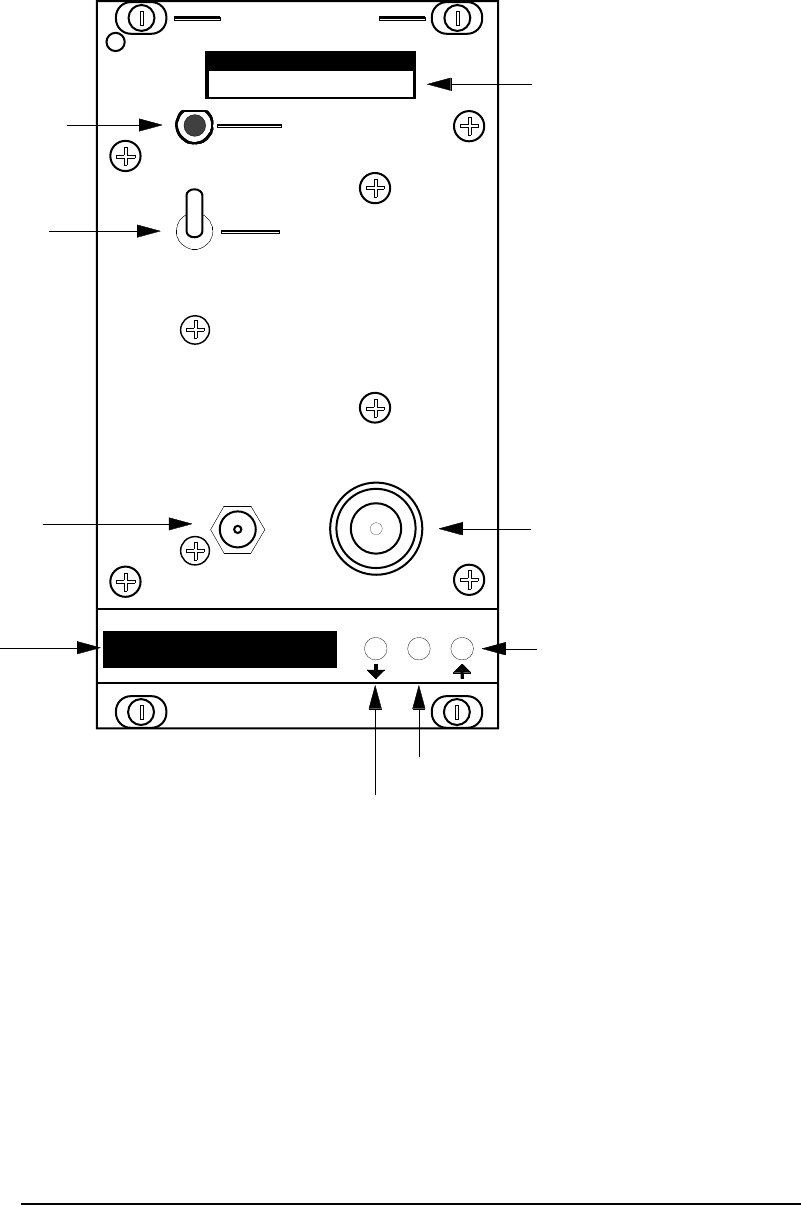
4.1 VR-3A130 Receiver Front Panel
RECEIVER
MODEL IDENTIFIER
SQ. DISABLE
N
O
RMO
FF
RF NI
REFERENCE
INPUT
RECE VERI
SQUELCH DISABLE
ON / OFF SWITCH
TYPE N RF
INPUT JACK
SMA REFERENCE
INPUT JACK
FREQUENCY
INDICATOR
FREQUENCY
DECREASE BUTTON
FREQUENCY
INCREASE BUTTON
OPTIONS BUTTON
*
Daniels Electronics Ltd
MADE IN CANADA
MADE IN CANADA
VR-3A130-SYD210
AM3RXM1A
DE DANIELS
ELECTRONICS
4-2 Frequency Select Handle Instruction Manual
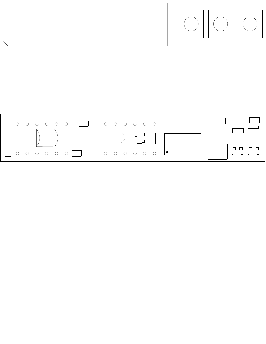
4.2 Frequency Select Handle Component Layout
R8
10K
C4
100nF
R9
10K
R1
10K
C5
100nF
C2
22pF
R4
6K8
C1
22pF
X1
8MHz
U1
16C63A
D6
BAS16
D1
BAS16 D2
BAS16
D3
BAS16
R5
10K
D4
BAS16
R2
10K R3
10K
D5
BAS16
R6
475
R7
10K
U3
78L05
C3
22uF
SW1SW2SW3
U2
PDSP 1881
PCB 50088-04
FSH3M1
VICTORIA B.C.
ELECTRONICS LTD.
DANIELS
ELECTRONICS LTD.
DANIELS
DWG No: FSH3M2B
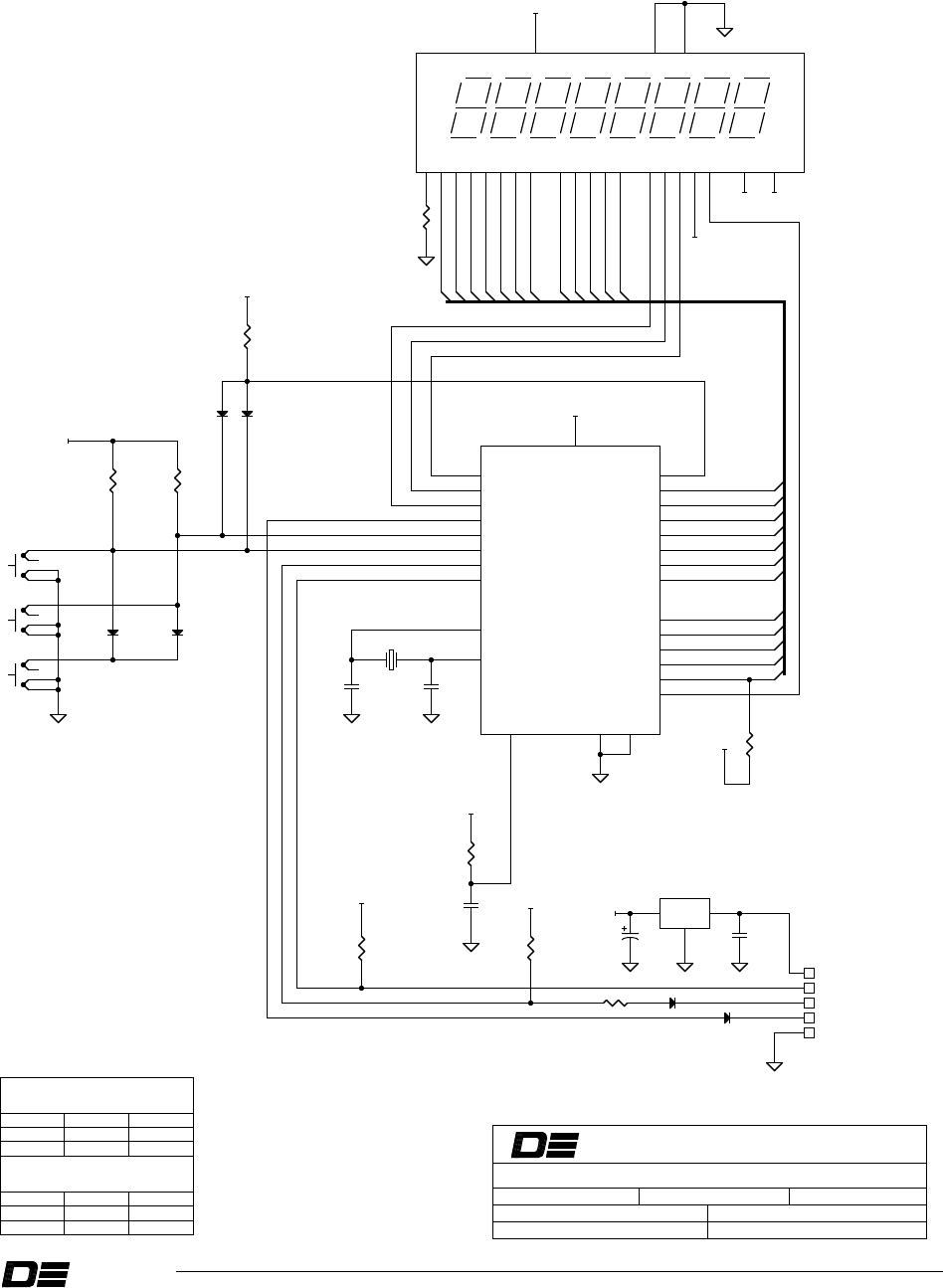
4.3 Frequency Select Handle Schematic Diagram
Frequency Select Handle Instruction Manual 4-3
DWN BY: Paul Ellis
BOARD REV: V 04BOARD No: 50088-04
DATE: 01 December 99
TITLE: FREQUENCY SELECT HANDLE SCHEMATIC DIAGRAM
Power Up
Sout
Sin
HIGHEST REFERENCE DESIGNATORS
UNUSED REFERENCE DESIGNATORS
-----
-----
-----
-----
-----
-----
-----
-----
-----
-----
-----
-----
-----
-----
-----
-----
-----
-----
DWG REV DATE:
APRVD:
10K0
R2 10K0
R3
A0
A1
A2
A3
A4
A0
A1
A2
A3
A4
Vcc GND
D7 D0 A4 A0 /WR
/RD
/CE
/FL
/RST CLS CLK
3029282726252120 106543 13191421 11 12
15 16 18
U2
PDSP1881
100nF
C5
6K81
R4
Rc5
Rc6
Rc7
Ra4
Ra5
Rc0
Rc1
Rc2
Rc3
Rc4
MCLR Gnd Gnd
OSC1
OSC2
Rb0
Rb1
Rb2
Rb3
Rb4
Rb5
Rb6
Rb7
Ra0
Ra1
Ra2
Ra3
Vcc
16
17
18
11
12
13
15
14
20
81
24
21
22
23
25
26
27
28
2
3
4
5
19
6
7
9
10
U1
16C63A
BAS16
D1 BAS16
D2
10K0
R1
J2
J3
J1
J5
1
2
3
4
Option
SW3
1
2
3
4
Down
SW2
1
2
3
4
Up
SW1
J4
D0
D1
D2
D3
D4
D5
D6
10K0
R5
IN
OUT
GND
1
2
3
78L05
U3
100nF
C4
22pF
C1 22pF
C2
8 MHz
X1
BAS16
D5
D0
D1
D2
D3
D4
D5
D6
BAS16
D3 BAS16
D4
10K0
R7
R6
0R0
1
2
10K0
R8
C3
22uF
BAS16
D6
10K0
R9
/CE
/RD
/WR
+5Vdc
+5Vdc
+5Vdc
+5Vdc
+5Vdc
+5Vdc
+5Vdc
+5Vdc
+5Vdc
+5Vdc
+5Vdc

DE DANIELS
ELECTRONICS
4-4 Frequency Select Handle Instruction Manual
This Page Intentionally Left Blank

DEDANIELS
ELECTRONICS
Frequency Select Handle Instruction Manual 5-1
5 PARTS LISTS
5.1 Frequency Select Handle Electrical Parts List
Ref.
Desig Description Part No.
C1, C2 CAP., SM, 22pF CER., 0805, C0G 1008-1A220J1G
C3 CAP., 22uF DIP. TANT., 20%,20V 1054-6G226M20
C4, C5 CAP., SM,100nF CER,0805,X7R,50 1008-5A104K5R
D1-D6 DIODE, BAS16, SWITCHING, SOT23 2100-BAS16000
PCB PCB, FREQUENCY SELECT HANLE 4312-90500884
R1-R3 RES., SM, 10K0 0805, 1%,100ppm 1150-4A1002FP
R4 RES., SM, 6K81 0805, 1%,100ppm 1150-3A6811FP
R5 RES., SM, 10K0 0805, 1%,100ppm 1150-4A1002FP
R6 RES., SM., ZERO OHM JUMPER. 1150-0A0R0000
R7-R9 RES., SM, 10K0 0805, 1%,100ppm 1150-4A1002FP
SW1-SW3 SWITCH, SM/PB, SPST/MOM,SEALED 5238-309J05NW
U1 IC, PIC16C63A-20I,M/CTR,SSOP28 2380-16C63S28
U2 DISPLAY, 8CHAR,5x7 DOT MTX,YEL 2018-D857330Y
U3 IC, 78L05AB, +5.OV REG., TO-92 2205-78053T92
X1 RESONATOR, SM, 8.0MHz, CERAMIC 1575-8001816A

DE DANIELS
ELECTRONICS
5-2 Frequency Select Handle Instruction Manual
5.2 Frequency Select Handle Mechanical Parts List
Description Part No. Qty.
HOUSING, 0.1",5 POS.,MALE TERM 5021-HM05L001 1
HOUSING, 0.1",5 POS.,FEM. TERM 5021-HF05L002 1
LABEL, 3537-40121010 1
SHIELD, 3702-67201305 1
TERMINAL, CRIMP, MALE,22-24,Au 5021-TM22B001 5
TERMINAL, CRIMP, FEM.,22-24,Au 5021-TF22B002 5
WIRE, PVC/STRAND., 22AWG,BLACK 7110-22S07300 18 cm
WIRE, PVC/STRAND., 22AWG, RED 7110-22S07302 18 cm
WIRE, PVC/STRAND., 22AWG, ORG. 7110-22S07303 18 cm
WIRE, PVC/STRAND.,22AWG,YELLOW 7110-22S07304 18 cm
WIRE, PVC/STRAND., 22AWG, VIO. 7110-22S07307 18 cm

DE DANIELS
ELECTRONICS
Frequency Select Handle Instruction Manual 6-1
6 REVISION HISTORY
ISSUE
DATE
DESCRIPTION AND (REASON)
1 Feb 00 •Issue 1

DE DANIELS
ELECTRONICS
6-2 Frequency Select Handle Instruction Manual
This Page Intentionally Left Blank