Electronic Systems Technology ESTEEM195EG-1 ESTEEM 195Eg User Manual Chapter 0 Front Cover 195Eg
Electronic Systems Technology ESTEEM 195Eg Chapter 0 Front Cover 195Eg
Contents
user manual ch 1 to 2

ESTeem MODEL 195Eg
USER’S MANUAL
Manual Revision 2.5
June 2008
Electronic Systems Technology, Inc.

ESTeem MODEL 195Eg
USER’S MANUAL
Manual Revision 2.5
Firmware Version 302.8.102 and above
June 2008
Prepared by: Date:
Name: Eric P. Marske
Title: Product Manager
Approved by: Date:
Name: Tom L. Kirchner
Title: President
COPYRIGHT INFORMATION
This manual and the firmware described in it are copyrighted by EST, with all rights reserved. Under the copyright laws, this manual or the firmware
internal to the ESTeem unit may not be copied, in whole or part, without the written consent of EST. Under the law, copying includes translating into
another language.
Electronic Systems Technology (EST) cannot guarantee that you will receive notice of a revision to the firmware described in the manual, even if
you have returned a registration/warranty card received with the product. You should periodically check with your authorized EST dealer or call
factory direct.
EST and the EST logo are registered trademarks of Electronic Systems Technology, Inc. Simultaneously published in the United States and
Canada. All rights reserved.
WARRANTY INFORMATION
Electronic Systems Technology, Inc., (hereinafter EST) expressly warrants its products as free of manufacturing defects for a period of one year
from the date of sale to first user/customer.
THERE ARE NO OTHER WARRANTIES, EXPRESS OR IMPLIED AND THERE IS EXPRESSLY EXCLUDED ALL WARRANTIES OF
MERCHANTABILITY OR FITNESS FOR A PARTICULAR PURPOSE. NO OTHER WARRANTY GIVEN BY ANY EMPLOYEE, AGENT,
DISTRIBUTOR OR OTHER PERSON WITH RESPECT TO THE PRODUCT SHALL BE BINDING ON EST.
LIMITATION OF LIABILITY:
EST's liability shall be limited to refunding of purchase price, repair or replacement of product.
IN NO EVENT SHALL EST HAVE LIABILITY FOR CONSEQUENTIAL, INCIDENTAL, SPECIAL OR EXEMPLARY DAMAGES CAUSED
DIRECTLY OR INDIRECTLY BY THE PRODUCT, INCLUDING BUT NOT LIMITED TO ANY INTERRUPTION OF SERVICES, LOSS OF
BUSINESS OR ANTICIPATORY PROFITS. IN NO EVENT SHALL EST BE LIABLE FOR ANY DAMAGES WHATSOEVER IN EXCESS OF THE
PURCHASE PRICE OF THE PRODUCT.
In the event that a unit or part requires replacement or factory servicing, the following conditions apply:
a) Customer must obtain from EST an authorized RMA (Return Materials Authorization) number (call 509-735-9092 Customer Support)
before shipment of product or parts to EST for any reason;
b) If the whole unit is shipped, it must be in its original carton and shipping components, or a carton and shipping components supplied by
EST, or if parts only are shipped, they must be packaged and cushioned so as to prevent damage in transit and shipped freight prepaid;
PRODUCT WILL BE CONSIDERED OUT OF WARRANTY IF:
a) If the product is damaged due to improper or abnormal use, abuse, mishandling, accident or improper maintenance or failure to follow
operating instruction;
b) If the product is defective as a result of sand, dirt, or water damage;
c) If any factory-sealed enclosure has been opened or shows evidence of an attempt to be opened;
d) If defects or damage are caused by the use of unauthorized parts or unauthorized service;
e) If the product has had its serial numbers altered or removed.
Warranty repair form must be accompanied by proof of user's purchase of unit. Product must be shipped to the manufacturer at the following
address:
Electronic Systems Technology
415 North Quay Street
Building B-1
Kennewick, Washington USA 99336
ADDITIONAL SERVICE:
If EST releases an improvement update to firmware internal to the ESTeem unit during the 90 day period after the unit was purchased by the first
user/customer, EST will update the applicable unit with the revised version at no charge other than for UPS handling and shipping to and from your
location to the EST factory. Return of any such item must be accompanied with proof of purchase.

TABLE OF CONTENTS
Revised: 18 Jun 08 Page 1 EST P/N AA107G
CHAPTER 1 – INTRODUCTION
Before You Begin 1-1
Model 195Eg Overview 1-1
Model 195Eg Configuration Modes 1-1
Access Point Modes ---------------------------------------------
1-2
Access Point Repeater ---------------------------------------------
1-3
Self-Healing Mesh Network ---------------------------------------------
1-3
Station (802.11g Client) Modes ---------------------------------------------
1-3
Serial Applications (Optional) ---------------------------------------------
1-4
CHAPTER 2 – CONFIGURATION DIAGRAMS
Model 195Eg Access Point Configurations 2-1
Figure 1: Single Access Point Bridge Diagram ---------------------------------------------
2-1
Figure 2: Multiple Access Point Bridge Diagram ---------------------------------------------
2-1
Figure 3: Access Point Router Diagram ---------------------------------------------
2-2
Figure 4: Access Point Masquerade Diagram ---------------------------------------------
2-2
Model 195Eg Access Point Repeater with Clients Configurations 2-3
Figure 5: Access Point Bridge Repeater with Clients Diagram ---------------------------------------------
2-3
Figure 6: Access Point Router Repeater with Clients Diagram ---------------------------------------------
2-3
Figure 7: Access Point Masquerade Repeater with Clients Diag. ---------------------------------------------
2-4
Model 195Eg Building to Building Configurations 2-4
Figure 8: Building to Building Configuration Diagram ---------------------------------------------
2-4
Figure 9: Building to Building with Repeater Diagram ---------------------------------------------
2-5
Figure 10: Building to Building Router Diagram ---------------------------------------------
2-5
Model 195Eg Complete Wireless Solutions 2-6
Figure 11: Complete Bridge Network Solutions Diagram ---------------------------------------------
2-6
Figure 12: Complete Router Network Solutions Diagram ---------------------------------------------
2-7
Model 195Eg Serial Network Configurations 2-8
Figure 13: Point to Point Serial Diagram ---------------------------------------------
2-8
Figure 14: Point to Point with Repeater Serial Diagram ---------------------------------------------
2-8
Figure 15: Multi-point Serial Diagram ---------------------------------------------
2-9
Figure 16: Ethernet and Serial Diagram ---------------------------------------------
2-9
CHAPTER 3 – STARTING OUT
Overview 3-1
Quick Start Guide ---------------------------------------------
3-1
Model 195Eg Hardware Layout 3-1
Required Hardware ---------------------------------------------
3-1
Front Panel Overlay Diagram ---------------------------------------------
3-2
Antenna Port Overview ---------------------------------------------
3-2
Antenna Configuration ---------------------------------------------
3-3
Hardware Configuration Diagram ---------------------------------------------
3-3

TABLE OF CONTENTS
Revised: 18 Jun 08 Page 2 EST P/N AA107G
ESTeem Discovery Utility 3-5
Installation ---------------------------------------------
3-5
Operation ---------------------------------------------
3-6
Configuring the IP Address ---------------------------------------------
3-6
Using The RS-232 Interface 3-7
Installing ESTeem Utility Program ---------------------------------------------
3-7
Programming Using the RS-232 Port ---------------------------------------------
3-7
CHAPTER 4 – WEB CONFIGURATION
Logging Into Web Configuration Manager 4-1
Web Configuration Manager 4-2
Top Menu --------------------------------------------- 4-2
Setting ModemID Field --------------------------------------------- 4-2
Status Menu --------------------------------------------- 4-3
System Log Screen --------------------------------------------- 4-5
Setup Screen --------------------------------------------- 4-5
Advanced Configuration Screen --------------------------------------------- 4-6
Backup Screen --------------------------------------------- 4-6
Restore Screen --------------------------------------------- 4-7
Software Update --------------------------------------------- 4-8
System Reboot --------------------------------------------- 4-8
CHAPTER 5 – EXAMPLE CONFIGURATIONS
Programming Example 5-1
Programming Example #1 Diagram --------------------------------------------- 5-1
Programming Example #2 Diagram --------------------------------------------- 5-2
Table 1: Example System Configuration Table --------------------------------------------- 5-2
Example 1 – Plant Network (Access Point Router Repeater) 5-3
Example 2 –Repeater (Access Point Bridge Repeater) 5-13
Example 3 – Remote Building (Access Point Bridge Repeater) 5-18
Example 4 – EtherStation Mode 5-19
Example 5 – Station Router Mode 5-21
Example 6 – Station Masquerade Mode 5-25
CHAPTER 6 – SERIAL APPLICATIONS
Serial Overview 6-1
Serial Connections 6-1
Second Ethernet Port --------------------------------------------- 6-1

TABLE OF CONTENTS
Revised: 18 Jun 08 Page 3 EST P/N AA107G
Serial Configuration 6-1
CHAPTER 7 – REPEATING FEATURES
Overview 7-1
ESTeem Mesh Network 7-1
Configuration --------------------------------------------- 7-1
Spanning Tree Protocol (STP) 7-2
Overview --------------------------------------------- 7-2
Phases --------------------------------------------- 7-3
Priority and Path Cost --------------------------------------------- 7-4
Root Bridge --------------------------------------------- 7-4
Redundant Backup 7-5
CHAPTER 8 – ANTENNA SETUPS
Antenna and Cable Configurations (Pole Mount) 8-1
Antenna and Cable Configurations (Cabinet Mount) 8-2
Coaxial Cable Attenuation 8-2
Antenna Diversity 8-4
Antenna Port Selection 8-4
Assembling the AA195PM Outdoor Pole Mounting Kit 8-4
Model 195Eg Series with Direct Mount Dual Diversity Antennas 8-11
Model 195Eg Direct Mount Antennas with Surge Protection 8-12
Model 195Eg Series with External Mount Antenna 8-13
Model 195Eg External Mount Antenna with Surge Protection 8-14
Model 195Eg Series Cabinet Mount Antenna 8-15
Fresnel Zone 8-16
APPENDIX A – FCC INFORMATION
APPENDIX B – SPECIFICATIONS
195Eg Specifications --------------------------------------------- B-1
Case Diagram --------------------------------------------- B-2
Antenna Specifications --------------------------------------------- B-3
APPENDIX C – INTERFACE PORTS
Ethernet Interface --------------------------------------------- C-1
Setting DHCP Server --------------------------------------------- C-1
RS-232 Programming Port Pin-Out --------------------------------------------- C-2
RS-232 Data Port Pin-Out --------------------------------------------- C-2

TABLE OF CONTENTS
Revised: 18 Jun 08 Page 4 EST P/N AA107G
APPENDIX D – RADIO CONFIGURATION
Frequency of Operation --------------------------------------------- D-1
Setting Data Rates --------------------------------------------- D-1
Setting RF Power Level --------------------------------------------- D-3
Average RF Output Power --------------------------------------------- D-4
APPENDIX E – SECURITY
APPENDIX F – TROUBLESHOOTING
Testing Communication Link --------------------------------------------- F-1
Viewing RF Data Rates --------------------------------------------- F-2
Signal Strength vs Data Rates --------------------------------------------- F-4
Updating 192E to Operate with 195Eg --------------------------------------------- F-4
Setting Maximum Distance Value --------------------------------------------- F-6
Troubleshooting Tips --------------------------------------------- F-7
APPENDIX G – Utilities and Features
Using ESTeem Discovery Program --------------------------------------------- G-1
Using EtherStation Status Program --------------------------------------------- G-4
Setting Local Time 195Eg --------------------------------------------- G-5
Configuring Time Server --------------------------------------------- G-6
APPENDIX H – Quick Start Guide
CHAPTER 1
INTRODUCTION
Revised: 23 Jan 08 1-1 EST P/N AA107G
BEFORE YOU BEGIN
Thank you and congratulations on your purchase of the ESTeem
Model 195Eg Wireless Ethernet Radio Modem! This manual was
written to help both the first time and advanced user of the 195Eg
configure the radio modem for your application. If this your first
time configuring the 195Eg and you would like to get going as soon
as possible, we recommend using the 195Eg Quick Start Guide
provided with the modem. A copy of the guide is listed in the
appendix of this manual for your reference.
The ESTeem 195Eg is a very versatile wireless Ethernet networking device. To keep the manual usably short, many of the
application descriptions and programming details assume the user has a good working knowledge of the following network
concepts:
• General Ethernet networking and the configuration of LAN topologies
• Common Ethernet terminology and acronyms
• TCP/IP network protocol structure and how to configure TCP/IP networks and subnets
• How to identify and set the TCP/IP address on your computer
• Have administrator privileges to the computer and network you are configuring
• If using routing protocols, you must be able to identify and configure the network routers, gateways and firewalls
• You must be familiar with using web browser software such as Internet Explorer, Netscape or Mozilla
If you are unfamiliar with any of the above networking concepts, you may need to contact your network administrator for
assistance.
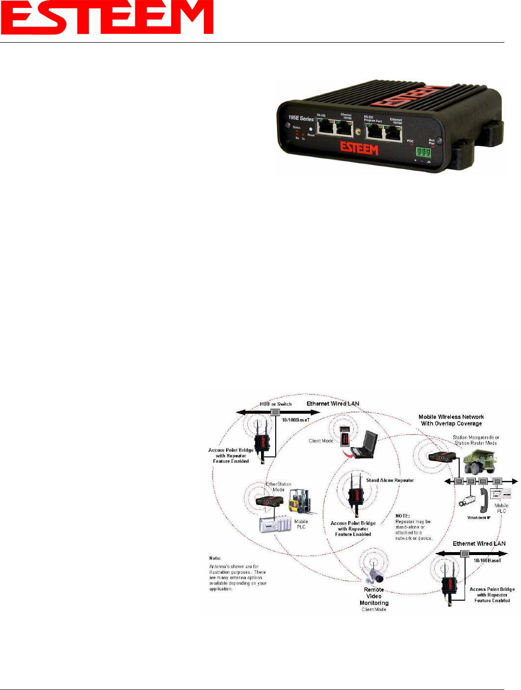
MODEL 195Eg OVERVIEW
The ESTeem Model 195Eg is an IEEE 802.11g
protocol compatible wireless LAN transceiver
that can be used to build a Wireless Local Area
Network (WLAN) for line-of-sight distances to
13 miles for fixed base and 5 miles for mobile
applications. The 195Eg can provide RF data
rates up to 54 Mbps and can have an optional
serial port for legacy RS-232 devices. The
Model 195Eg is also downward compatible with
IEEE 802.11b protocol networks. The IEEE
802.11 WLAN was designed to look and feel like
any IEEE 802 wired LAN. The Model 195Eg is
a very sophisticated networking device that can
be configured for multiple modes of operation
depending upon the needs of the wireless and
wired LAN system. The following configuration
modes are provided as an overview of the basic
network types, as all possible network
configurations can not be listed. For further help
in selecting the correct network type, please
contact Customer Support at 509-735-9092.
Figure 1- Access Point Bridge Diagram
CHAPTER 1
INTRODUCTION
Revised: 23 Jan 08 1-2 EST P/N AA107G
MODEL 195Eg CONFIGURATION MODES
The Model 195Eg can be configured for multiple
modes of operation without any changes to the
hardware:
Access Point Modes
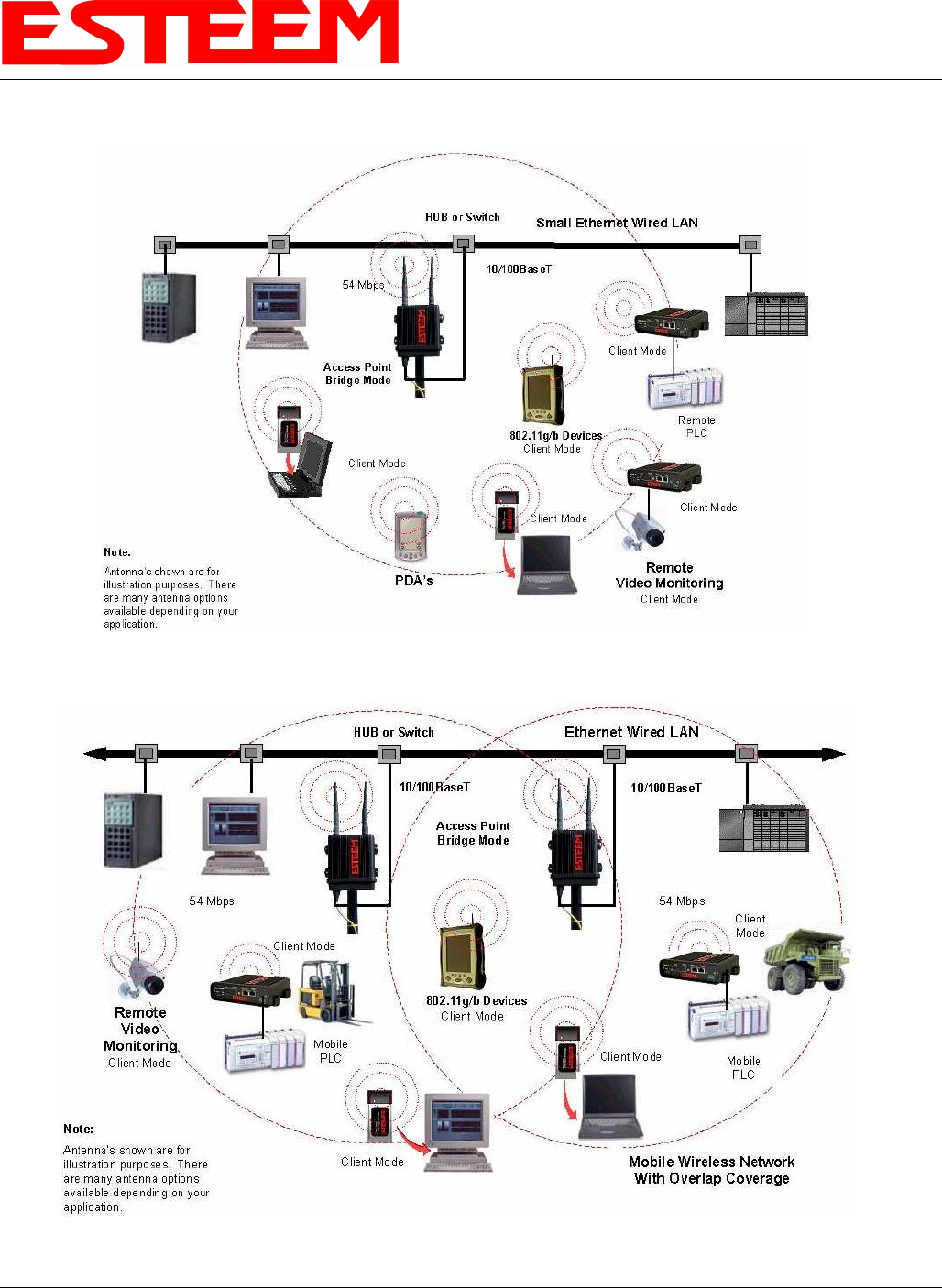
1. Access Point Bridge Mode. When the
Model 195Eg is configured as an Access
Point it will provide a wireless bridge from a
hardwired Local Area Network (LAN) to
laptops, office computers, Personal Digital
Assistants (PDA’s), video cameras, PLC’s,
etc. that have integral or external 802.11g or
802.11b wireless devices or other Model
195Eg modems in client modes. Multiple
Access Point Bridge modems can be
physically connected to the same network
(LAN) or through a radio link using the
Access Point Repeater mode to provide
overlapping, seamless Ethernet communication for mobile devices. The ESTeem Model 195Eg in Access Point Bridge mode
will pass all network traffic between connected devices including global network broadcasts. See Figure 1.
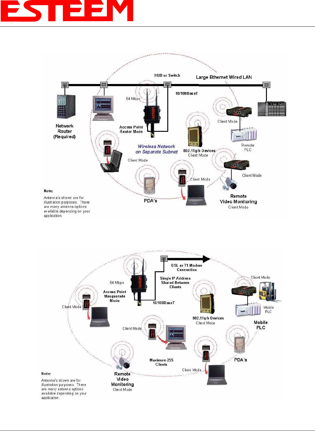
2. Access Point Router Mode. In this mode the ESTeem Model 195Eg will function as a router between the wired Ethernet
network, connect to the 195Eg’s Ethernet port, and the wireless network of 802.11g/b clients and other 195Eg’s in repeater
peer mode. As in all standard router configurations, the wireless and wired Ethernet networks will need to be on separate
subnets. To communicate from the wired Ethernet network to devices on the wireless network, a separate router (in addition to
the Model 195Eg) is required. The 195Eg in Access Point Router mode will pass network traffic for connected devices but
will block global network broadcasts from the wired network. This mode of operation should be used instead of the Access
Point Bridge mode when a
separation between networks is
required or the ESTeem is
connected to larger LAN Networks
that will continuously send global
network broadcasts (Figure 2).
3. Access Point Masquerade Mode.
The Access Point Masquerade
mode is a special use of the Access
Point mode where the Model 195Eg
will connect 802.11g or 802.11b
wireless devices as clients into a
single static IP address on a wired
network. Data requests from the
wireless network will be processed
through the Access Point
Masquerade 195Eg, but any request
from the wired Ethernet network to
devices on the wireless network will
Figure 2 – Repeater Mode Diagram
Figure 3- Access Point Masquerade Diagram
CHAPTER 1
INTRODUCTION
Revised: 23 Jan 08 1-3 EST P/N AA107G
be rejected similar to the operation of a “firewall”. The 195Eg will hide all the IP addresses connected on the wireless link.
You should use this mode of operation if Model 195Eg is connected directly to the Internet with a static IP address (DSL, T1,
etc.) and you want the wireless clients to access the information through the Model 195Eg (Figure 3). This mode should also
be used for attaching the Model 195Eg to a network where few IP addresses are available or a firewall for the wireless clients
is required.
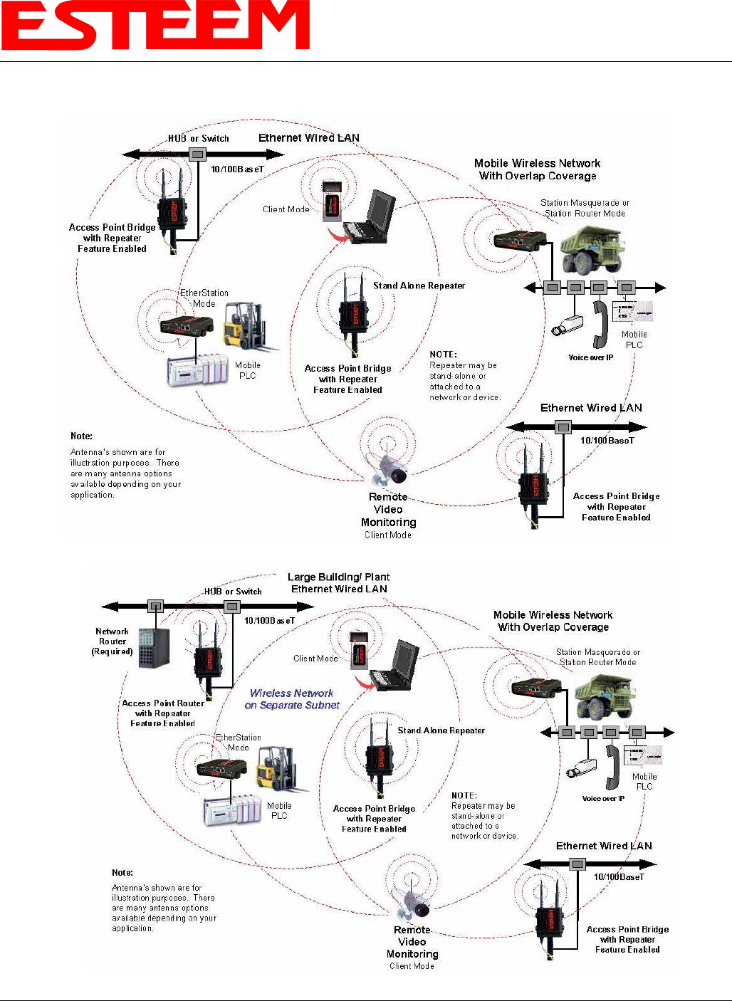
4. Access Point Repeater. The Access Point Repeater is a unique enhancement of the 802.11g Access Point mode only
available the ESTeem Model 195Eg. The Access Point Repeater can be used with any of the above Access Point modes.
With this repeater feature enabled, the Model 195Eg Access Points do not have to be hardwired together on the same physical
LAN to provide seamless Ethernet communication for roaming 802.11g/b Clients. In addition to greatly extending the Access
Point canopy range, the Model 195Eg will also bridge any Ethernet device or Ethernet network connected to the unit over this
same wireless Ethernet network. This mode gives the user the features of a point to multi-point bridge network but also allows
802.11g/b Client devices or the Model 195Eg in the Client mode to simultaneously roam under the network canopy.
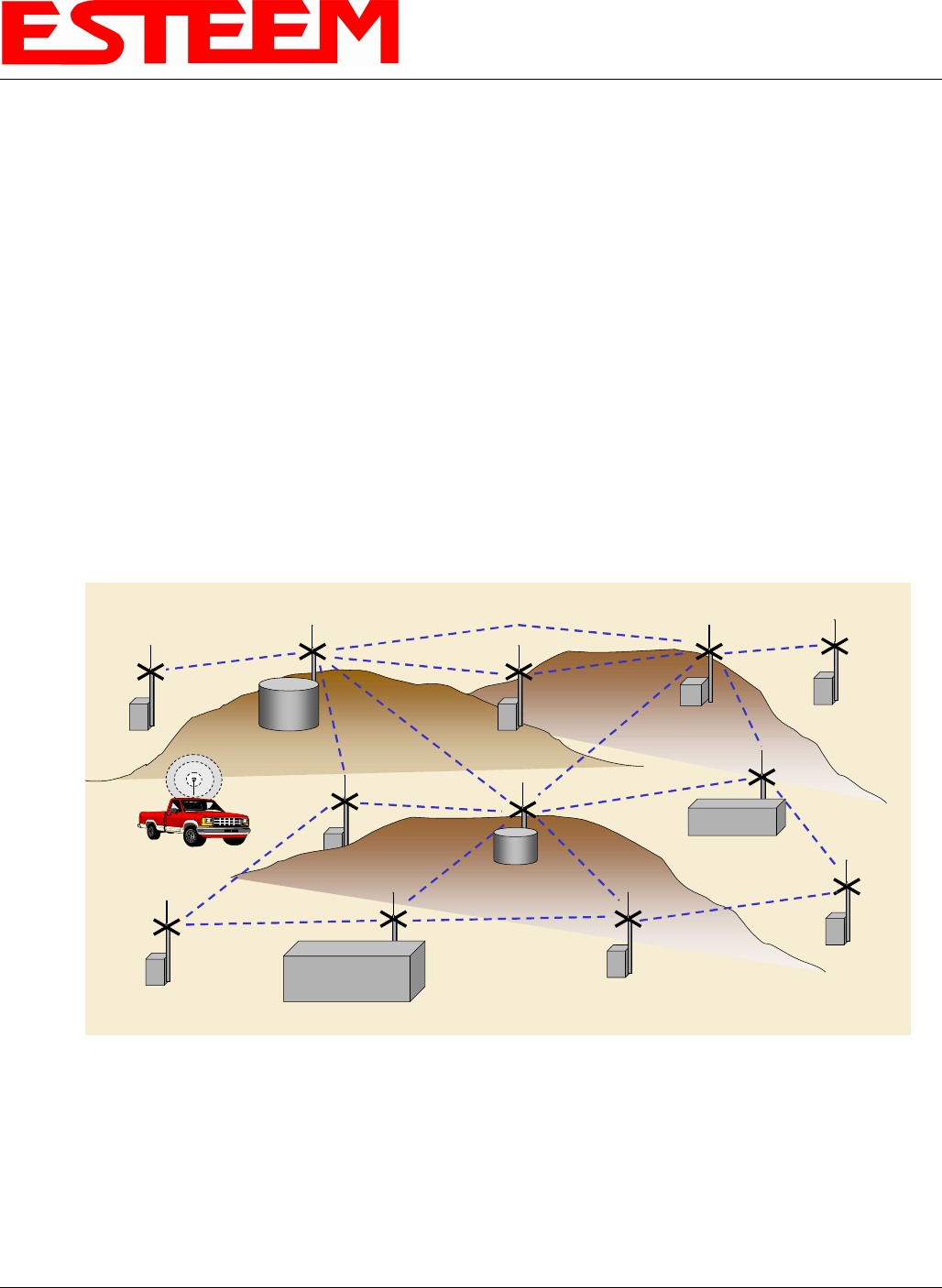
5. Self-Healing Mesh Network. If multiple Access Point Repeater routes are configured to the same destination ESTeem, the
195Eg will create a “self-healing” mesh network by automatically re-routing data through alternate paths to reach its
destination if the primary path is inoperable. The routing and priority of alternate paths is completely user configurable.
See Figure 4.
Station (802.11g Client) Modes
6. EtherStation Mode. This is a unique feature of the Model 195Eg when used in any Access Point network. When the 195Eg
is configured in the EtherStation Mode and attached to a single Ethernet Device, the Model 195Eg will emulate an 802.11g
PCMCIA wireless card in functionality for communication as an 802.11g client. The 195Eg will seamless roam under the
radio canopy of Access Point and can provide greatly increased range over a Wireless LAN Card for mobile Ethernet devices
such as vehicles, forklifts, cranes, etc (Figures 1-3).
7. Station Router Mode. The Station Router mode will also function as an 802.11g client, similar to EtherStation, but will allow
multiple Ethernet devices to be connected to a single 195Eg (Figure 3). The 195Eg will function as a router between the
wireless client mode and the wired Ethernet devices connected to the Ethernet port. Similar in configuration to the Access
Main Office
Remote Office
Vehicles
Remote Site
Remote Site
Remote Site
Access
Point/Repeater
Access
Point/Repeater
Remote Site
Access
Point/Repeater
Access
Point/Repeater
Access
Point/Repeater
Remote Site
Access
Point/Repeater
Remote Site
Access
Point/Repeater
Remote Site
Access
Point/Repeater
Remote Site
Access
Point/Repeater
Access
Point/Repeater Access
Point/Repeater
Access
Point/Repeater
Remote Site
Remote Site
Client Mode
Figure 4 – Mesh Network Diagram
CHAPTER 1
INTRODUCTION
Revised: 23 Jan 08 1-4 EST P/N AA107G
Point Router mode, the wireless and wired Ethernet networks will need to be on separate subnets. To communicate from
wireless network to devices on the wired Station Router network, a separate router (connected to the Ethernet side of the
Access Point) is required. This mode would be used where multiple Ethernet devices will be connected to a single Model
195Eg in a mobile client application and the connected Ethernet devices will need to be accessible from the Access Point’s
LAN network.
8. Station Masquerade Mode. The Station Masquerade Mode is another mode where multiple devices will be connected to a
single ESTeem in a mobile or Client application, but unlike the Station Router mode, the Station Masquerate will consolidate
all connected Ethernet devices to a single IP address on the network. The devices connected to the Station Masquerade 195Eg
will be able to access information from both the wireless and wired LAN, but will be inaccessible the other way similar in
application to a firewall. This mode would be used where multiple Ethernet devices will be connected to a single Model
195Eg in a mobile application and the IP addresses for each device will be hidden from the LAN connected to the Access
Point. See Figure 3.
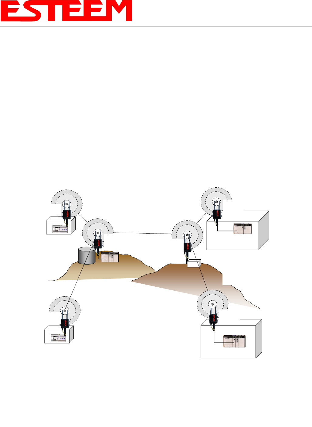
9. Serial Applications (Optional). The ESTeem 195Eg can optionally be installed with an RS-232 data port for serial data
applications run over the broadband link (Figure 5). The serial over broadband network can be used in a point-to-point or
point-to-multi-point application for networking serial (RS-232c) devices, providing serial connections to legacy hardware in a
new Ethernet network or providing for high-bandwidth devices (such as Video or Voice over IP) in an existing serial network.
Installing the serial port option also provides a second 10/100 Base-T Ethernet port that can be used to connect a second
Ethernet device without requiring a HUB/Switch or can be configured as an external Router port.
To begin setup of your wireless Ethernet network you must first configure the Model 195Eg for the mode desired. Chapter 2 will
show several examples of the different modes of operation to help select the correct mode for your application.
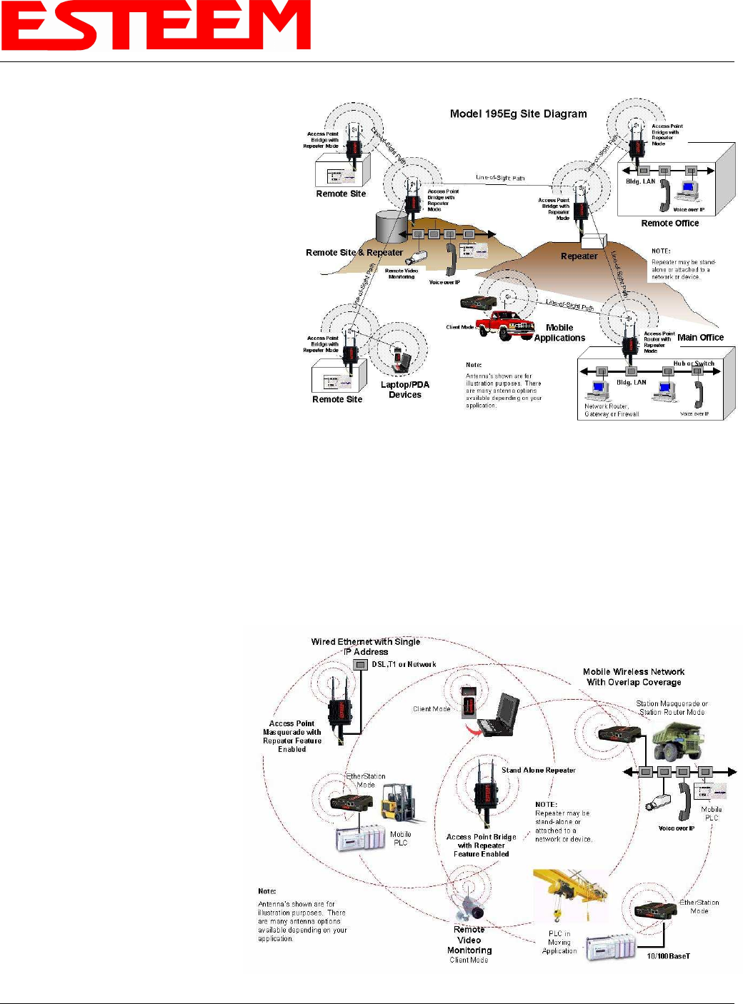
Remote Site & Repeater Repeater
Remote Site
Access Point
Bridge with
Repeater Mode
Remote Site
Access Point
Bridge with
Repeater
Mode
Access Point
Bridge with
Repeater
Mode
Access Point
Bridge with
Repeater Mode
Access Point
Bridge with
Repeater
Mode
Line-of-Sight Path
NOTE:
Repeater may be stand-
alone or attached to a
network or device.
Line-of-Sight Path
Line-of-Sight Path
Line-of-Sight Path
Line-of-Sight Path
Access Point
Bridge with
Repeater
Mode
Note:
Antenna’s shown are for
illustration purposes. There
are many antenna options
available depending on your
application.
Master PLC
RS-232 Data
Remote PLC
RS-232 Data
RS-232 Data
RS-232 Data
RS-232 Data
Figure 5 – Multi-point Serial Diagram
CHAPTER 2
CONFIGURATION DIAGRAMS
Revised: 23 Jan 08 2-1 EST P/N AA107G
MODEL 195Eg ACCESS POINT BRIDGE DIAGRAMS
Figure 1: Single Access Point Bridge Diagram
Figure 2: Multiple Access Point Bridge (Overlapping Coverage) Diagram
CHAPTER 2
CONFIGURATION DIAGRAMS
Revised: 23 Jan 08 2-2 EST P/N AA107G
MODEL 195Eg ACCESS POINT ROUTER DIAGRAM
MODEL 195Eg ACCESS POINT MASQUERADE DIAGRAM
Figure 3: Access Point Router Diagram
Figure 4: Access Point Masquerade Diagram
CHAPTER 2
CONFIGURATION DIAGRAMS
Revised: 23 Jan 08 2-3 EST P/N AA107G
MODEL 195Eg ACCESS POINT REPEATER AND CLIENT CONFIGURATION DIAGRAMS
Figure 5: Access Point Bridge Repeater with Clients Diagram
Figure 6: Access Point Router Repeater with Clients Diagram
CHAPTER 2
CONFIGURATION DIAGRAMS
Revised: 23 Jan 08 2-4 EST P/N AA107G
MODEL 195Eg ACCESS POINT REPEATER AND CLIENT CONFIGURATION DIAGRAMS (Cont.)
MODEL 195Eg BUILDING TO BUILDING CONFIGURATION DIAGRAMS
Figure 7: Access Point Masquerade Repeater with Clients Diagram
Figure 8: Building to Building Configuration Diagram
CHAPTER 2
CONFIGURATION DIAGRAMS
Revised: 23 Jan 08 2-5 EST P/N AA107G
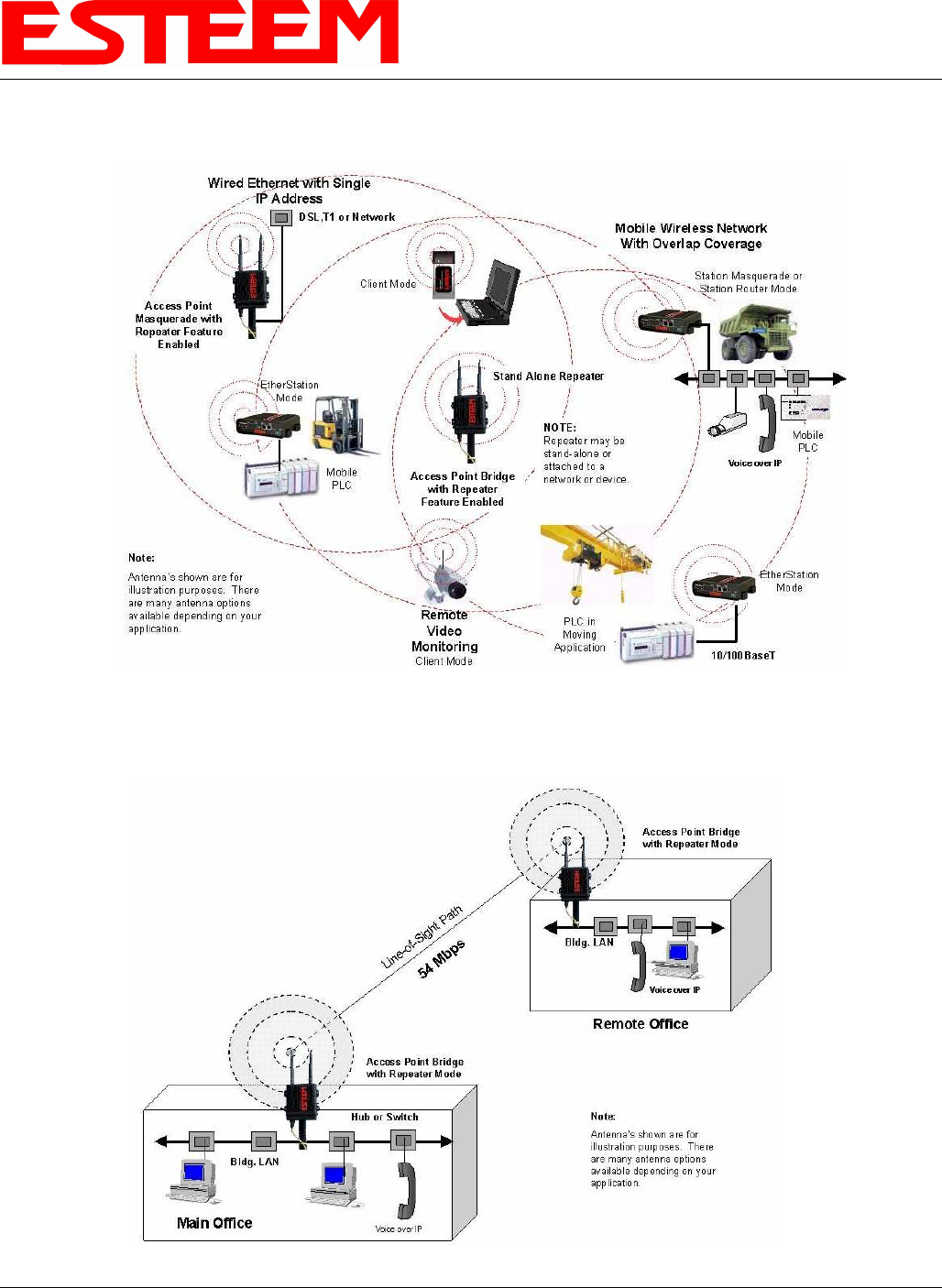
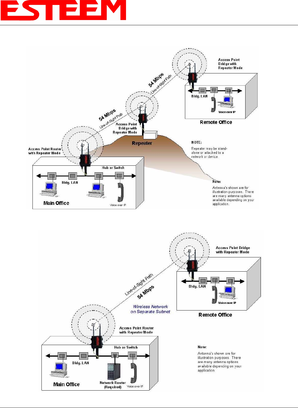
MODEL 195Eg BUILDING TO BUILDING CONFIGURATION DIAGRAMS (Cont.)
Figure 10: Building to Building Router Diagram
Figure 9: Building to Building with Repeater Diagram

CHAPTER 2
CONFIGURATION DIAGRAMS
Revised: 23 Jan 08 2-6 EST P/N AA107G
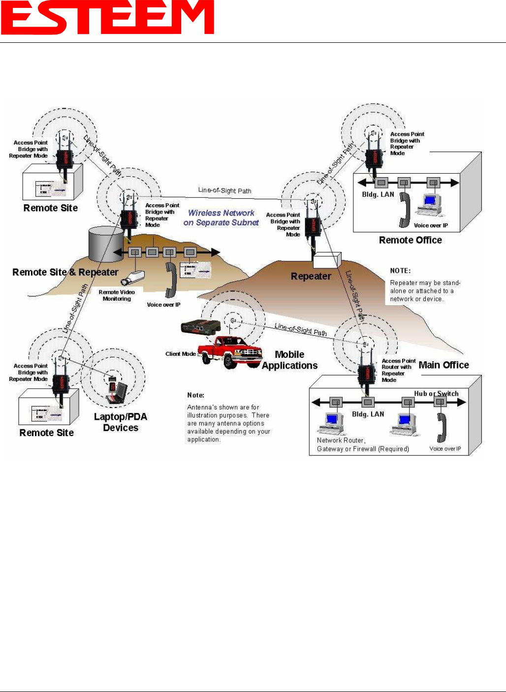
MODEL 195Eg COMPLETE BRIDGE SYSTEM CONFIGURATION DIAGRAMS
Figure 11: Complete Bridge Network Solutions Diagram
CHAPTER 2
CONFIGURATION DIAGRAMS
Revised: 23 Jan 08 2-7 EST P/N AA107G
MODEL 195Eg COMPLETE ROUTER SYSTEM CONFIGURATION DIAGRAMS
Figure 12: Complete Router Network Solutions Diagram
CHAPTER 2
CONFIGURATION DIAGRAMS
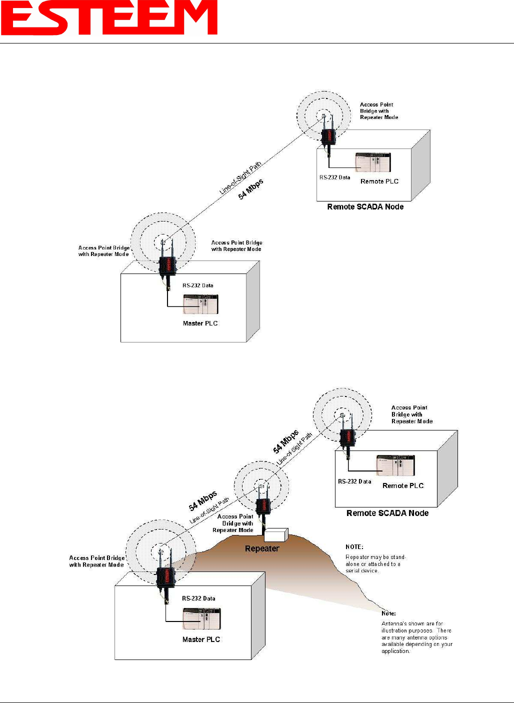
Revised: 23 Jan 08 2-8 EST P/N AA107G
Figure 13: Point to Point Serial Diagram
Figure 14: Point to Point With Repeater Serial Diagram
CHAPTER 2
CONFIGURATION DIAGRAMS
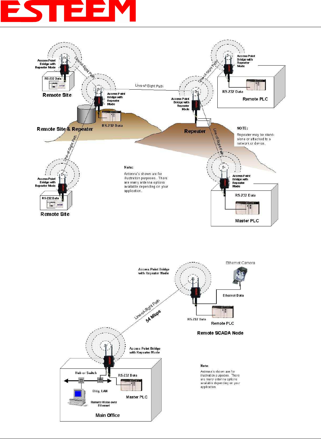
Revised: 23 Jan 08 2-9 EST P/N AA107G
Figure 15: Multi-point Serial Diagram
Figure 16: Ethernet and Serial Diagram