Electronic Systems Technology ESTEEM195EG-1 ESTEEM 195Eg User Manual 195Eg Chapter 8 Antenna Setup
Electronic Systems Technology ESTEEM 195Eg 195Eg Chapter 8 Antenna Setup
Contents
user manual ch 8
CHAPTER 8
ANTENNA SETUPS
Revised: 2 Jul 08 8-1 EST P/N AA107G
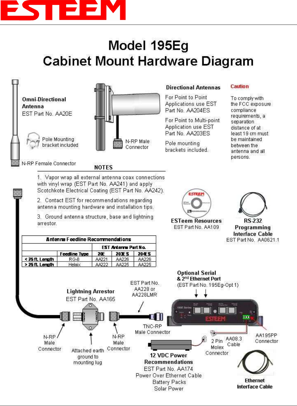
ANTENNA AND CABLE CONFIGURATIONS (POLE MOUNT)
EST offers different types of antennas for both indoor and outdoor configurations. To reduce potential radio interference to other
users, the antenna type and its gain should be so chosen that the equivalent isotropically radiated power (e.i.r.p.) is not more than
that permitted for successful communication.
Warning: Only the tested cable lengths and antennas provided by EST meet the FCC maximum peak output power
requirements. Any other combination of antennas or coax cables is not authorized. This device has been designed to operate in
a pole mount configuration with the antennas listed below, and having a maximum gain of 6 dB in a multi-point system or
19dB in a point to point network. Antennas not included in this list or having a gain greater 6 dB in a multi-point system or
19dB in a point to point network are strictly prohibited for use with this device. The required antenna impedance is 50 ohms.
Part Number: AA01S
•
••
• Omni-directional, rubber duck, direct mount, unity gain
antenna.
•
••
• Indoors and short range outdoor applications.
•
••
• There must be a minimum separation distance of 20
cm. from the antenna to the user. See Warnings.
Part Number: AA20DMEg
•
••
• Omni-directional direct mount antenna, 5 dBi gain.
•
••
• Indoor and outdoor applications.
•
••
• There must be a minimum separation distance of 20
cm. from the antenna to the user. See Warnings.
Part Number: AA20Eg
•
••
• Omni-directional external pole mount antenna, 6 dBi
gain with 3-ft. integral feedline and connector.
•
••
• Outdoor applications.
•
••
• Antenna port B is not used in this configuration.
•
••
• There must be a minimum separation distance of 20
cm. from the antenna to the user. See Warnings.
Part Number: AA203Eg
•
••
• Directional pole mount antenna, 6 dBi gain with 3-ft.
integral feedline and connector.
•
••
• Point to point and point to multi-point outdoor
applications.
•
••
• Antenna port B is not used in this configuration.
•
••
• There must be a minimum separation distance of 20
cm. from the antenna to the user. See Warnings.
Part Number: AA204Eg
•
••
• Directional pole mount antenna, 19 dBi gain with 3-ft.
integral feedline and connector.
•
••
• Point to point applications only.
•
••
• Maximum Output Power of 250mWatts (Power Level
= Low Power)
•
••
• Antenna port B is not used in this configuration.
•
••
• There must be a minimum separation distance of 50
cm. from the antenna to the user. See Warnings.
Transmit/Receive
Antenna Port
Receive Only
Antenna Port
Notes:
Antenna Port A is a transmit and receive port for use in all
applications.
Antenna Port B is a receive only port and is used for dual
diversity antennas applications only. This port is not used
for point to point applications.
Warnings:
Only pre-made coax cables from the factory used in
conjunction with either the AA20Eg omni-directional
and AA203Eg or AA204Eg directional antennas meet all
FCC Section 15.247(b) EIRP maximum power
requirements.
Use of the AA204Eg, directional antenna is limited to
fixed point to point applications only. In accordance
FCC Section 15.247(b)iii, this antenna must be
professionally installed. The installer must ensure the
system is used exclusively for fixed, point-to-point
applications and the ESTeem Model 195Eg is set for 0.25
Watts output power (Power Level = Min).
CHAPTER 8
ANTENNA SETUPS
Revised: 2 Jul 08 8-2 EST P/N AA107G
ANTENNA AND CABLE CONFIGURATIONS (CABINET MOUNT)
Warning: Only the tested cable lengths and antennas provided by EST meet the FCC maximum peak output power
requirements. Any other combination of antennas or coax cables is not authorized. This device has been designed to operate
in a cabinet mount configuration with the antennas listed below, and having a maximum gain of 7 dB in a multi-point system
or 11dB in a point to point network with the authorized ESTeem coax cables. Antennas not included in this list or having a gain
greater 7 dB in a multi-point system or 11dB in a point to point network with any other types or lengths of coax cable are
strictly prohibited for use with this device. The required antenna impedance is 50 ohms.
Part Number: AA20E
•
••
• Omni Directional Building Mount Antenna, 6 dBd gain
•
••
• Feedline minimums: 25 ft. RG-8 Cable or 50 ft. Heliax
Cable with AA228LMR and Lightning Arrestor (EST
P/N: AA165).
Part Number: AA203ES
•
••
• Directional Building Mount Antenna, 7 dBd gain
•
••
• Feedline minimums: 25 ft. RG-8 Cable or 50 ft. Heliax
Cable with AA228LMR and Lightning Arrestor (EST
P/N: AA165).
•
••
• Point to point and point to multi-point applications
Part Number: AA204ES* (Point-to-point ONLY)
•
••
• Directional Building Mount Antenna, 11 dBd gain
•
••
• Feedline minimums: 25 ft. RG-8 Cable or 50 ft. Heliax
Cable with AA228LMR and Lightning Arrestor (EST
P/N: AA165).
•
••
• Point to point applications only. See Warning.
COAXIAL CABLES
A 25-ft. length of RG-8 coax cable or 50-ft. length of ½”Heliax cable are the minimum cable lengths allowed for use with the above
antennas (AA20E, AA203ES, AA204ES) when the Model 195Eg is set at Max Power. Listed below are representative cable losses
in db/100 ft at the 2.4 GHz frequency range:
Feedline Type Attenuation
(dB/100 ft.) @ 2.4 GHz Additional RF Losses Attenuation (dB)
RG-8 (Solid) 7 AA228LMR (2.5’ TNC-MRP/N-
MRP) Jumper Cable 0.9
LMR 600 4.4 AA165 Lightning Arrestor 0.1
3/8" Heliax 6.5 All Coax Connector Terminations
(2 for every coax cable) 0.2
1/2" Heliax 3.5
7/8" Heliax 2
1.25" Heliax 1.6
In a severe noise environment it may be necessary to use a double shield type of coax cable such as RG-214/U in place of the RG-8.
This cable must be purchased from the factory to meet FCC requirements.
Warning:
Only pre-made coax cable systems (Cable, Lightning
Arrestor and AA228LMR jumper cable) from the factory
used in conjunction with either the AA20E omni-
directional and AA203ES or AA204ES directional
antennas meet all FCC Section 15.247(b) EIRP
maximum power requirements.
Use of the AA204ES, directional antenna is limited to
fixed point to point applications only. In accordance
FCC Section 15.247(b)iii, the operator or installer is
responsible for ensuring the systems is used exclusively
for fixed, point-to-point applications.

CHAPTER 8
ANTENNA SETUPS
Revised: 2 Jul 08 8-3 EST P/N AA107G
Note: A -3 dB loss means you have lost 1/2 of your signal or transmitter power. A +3 dB gain means you have doubled (x2)
your signal or transmitter power.
Example:
A 6 dB antenna will increase the radiated output power of a 1 watt transmitter to 4 watts {times 4 = 3 dB (x2) + 3 dB
(x2)} and increase the received signal strength to receiver times 4.
WEATHER PROOFING COAX CONNECTIONS
1. Coat the threads of the connectors with silicone lubricant prior to assembly (See Note 1) and hand tighten. Care should be
taken not to get any lubricant on the center conductor.
2. Wrap the connector assembly with a vapor barrier patch for weather proofing (See Note 2), ensuring to overlap onto the coax
cable approximately 1 1/2 inches.
3. Apply an electrical coating (sealing agent) over the vapor barrier patch for added protection (See Note 3).
Notes:
1. Dow Corning RTV-3140 or equivalent.
2. Suggested vendors:
VAPOR-WRAP
Decibel Products
3184 Quebec St.
Dallas, TX 75356
214-631-0310
VYNIL-MASTIC, P/N 2200
3-M Company
Customer Service
512-984-1800
3. SCOTCHKOTE, 3-M Company, or equivalent.
CHAPTER 8
ANTENNA SETUPS
Revised: 2 Jul 08 8-4 EST P/N AA107G
ANTENNA DIVERSITY
The dual diversity antenna configuration on the ESTeem Model 195Eg allows the radio to operate more efficiently in areas with
high reflections (such as indoors or in a city) and without direct line of sight (LOS) between the antennas. One of the most difficult
conditions to control in a radio system is the effect of a destructive reflected radio signal called mutipathing. Multipathing occurs
when waves emitted by the transmitter travel along a different path and interfere destructively with waves traveling on a direct line-
of-site path. The phenomenon occurs because waves traveling along different paths may be completely out of phase when they
reach the antenna, thereby canceling each other out. The dual diversity antenna configuration places a physical distance between the
antennas where one reflected signal will be out of phase, but the second will be not. The ESTeem Model 195Eg will sample both
antennas and select the best receive signal.
ANTENNA PORT SELECTION
The antenna ports on the Model 195Eg must be configured for either a single receive antenna (external mount antennas) or dual
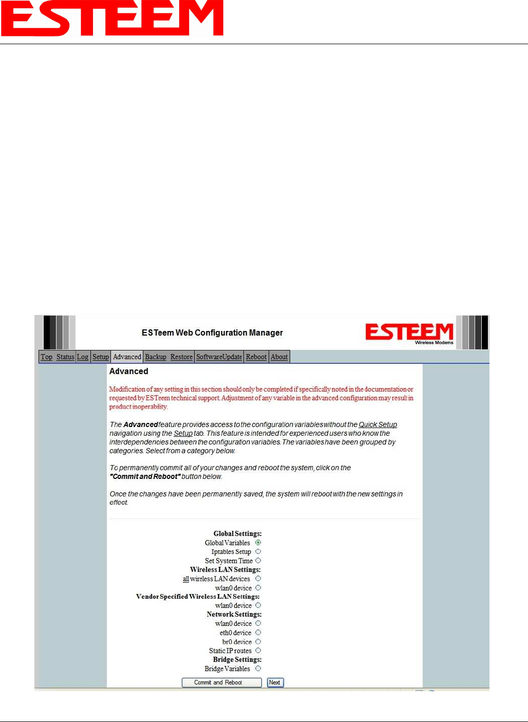
diversity antenna setup. To access the port configuration open ESTeem Web page using your computer’s Web Browser as per
instructions in Chapter 4. Select Advanced from the menu items and Radio Settings-wlan0 device (Figure 1).
Figure 1: Advanced Settings Menu
CHAPTER 8
ANTENNA SETUPS
Revised: 2 Jul 08 8-5 EST P/N AA107G
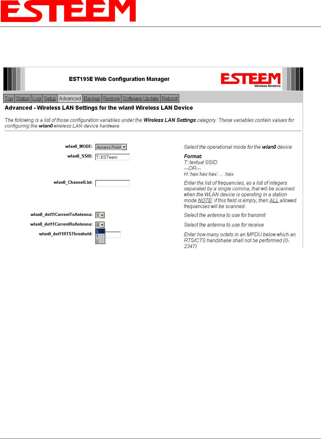
Press the next button and Figure 2 will be displayed. The receive antenna is configured by selecting the
wlan0_dot11CurrentRXAntenna drop down (Figure 2) and selecting the receive antenna. A value of 0 = Dual diversity (Both
antenna Ports A & B will be used to receive). A value of 1 = Single receive source (Antenna Port A only).
Figure 2: Receive Antenna Settings Menu
CHAPTER 8
ANTENNA SETUPS
Revised: 2 Jul 08 8-6 EST P/N AA107G
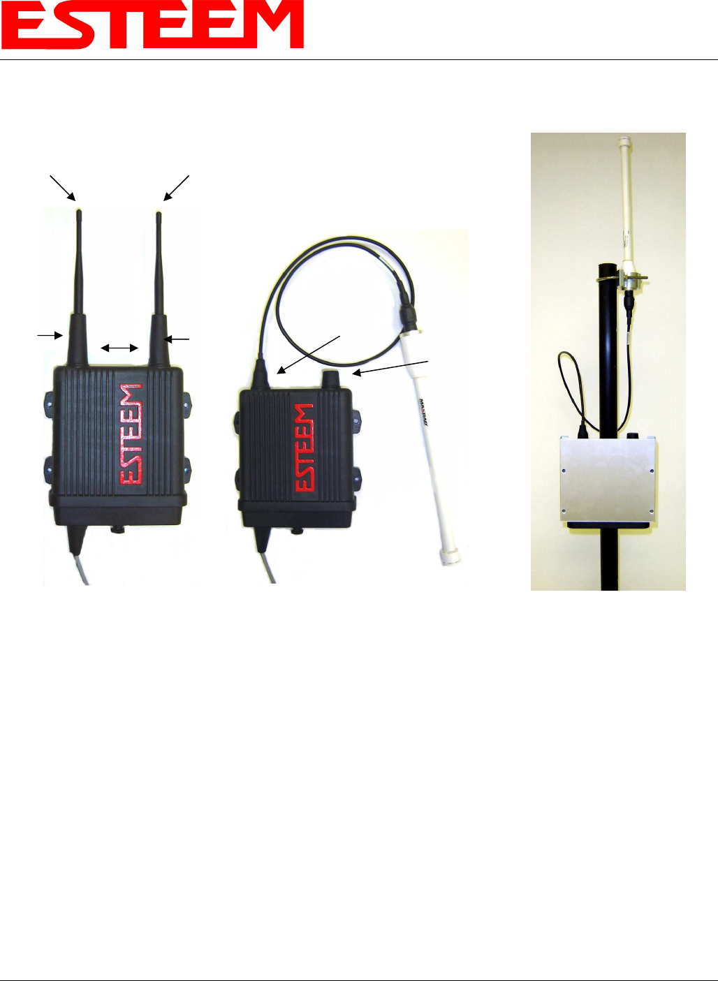
ASSEMBLING THE AA195PM TWO HOLE OUTDOOR POLE MOUNTING KIT
The AA195PM mounting kit contains everything required for pole mounting and weatherproofing the ESTeem Model 195Eg for
outdoor installations. The 195Eg with AA195PM mounting kit can be directly mounted to a round pole from 1.25” to a diameter of
2.25” OD. Any mounting structure greater than 2” requires hose clamp strapping run through the Pole Mount Brackets. The
mounting kit requires the following assembly:
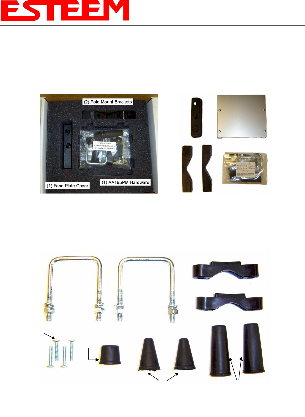
1. If you purchased an AA195PM mounting kit with your Model 195Eg, the kit will be packed in the same packing box as the
ESTeem (Figure 1).
2. Remove and inventory the two (2) Pole Mounting Brackets, one (1) Two-Hole Face Plate Cover (with single port cover
installed), one (1) Heat Shield and (1) AA195PM Hardware bag from the packing box (Figure 1). Report any missing or
damaged items to ESTeem Customer Support (509-735-9092 Phone) as soon as possible for replacement.
Figure 1: Packet Box Contents
Figure 2: AA195PM Hardware Contents
(2) Square Bend U-Bolts with Hardware
(2) Pole Mount Clamps
(4) 10-24 Pan Screws
(2) Ethernet
Cable Boot
(1) Weather Proof
Boot for Antenna
Port B (if not used)
(2) Direct Mount Antenna Boots for ESTeem
Approved Direct Mount Antenna Only
CHAPTER 8
ANTENNA SETUPS
Revised: 2 Jul 08 8-7 EST P/N AA107G
3. Inventory the AA195PM Hardware bag for all the components listed in Figure 2.
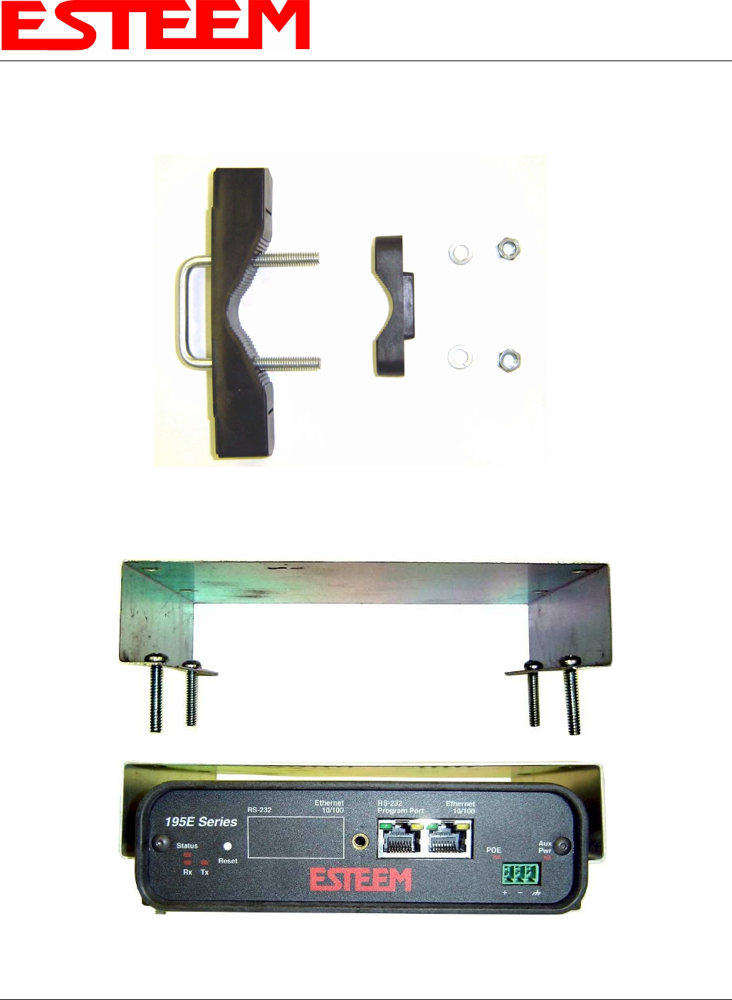
4. Assemble the two Pole Mounting Brackets with the included U-bolts, hardware and Pole Mount Clamps. Reference Figure 3.
5. Place the four supplied 10-24 x 1” Phillips Pan Head screws through the mounting holes of the Heat Shield and attach to the to
the top of the ESTeem 195Eg (Figure 4).
Figure 3: Pole Mount Assembly
Figure 4: Heat Shield Attachment
CHAPTER 8
ANTENNA SETUPS
Revised: 2 Jul 08 8-8 EST P/N AA107G
6. Attach the two Pole Mounting Brackets to the ESTeem Model 195Eg with the 10-24 x 1” Phillips Pan Head screws through
the top of the heat shield. Reference Figure 5 (Heat Shield removed for detail).
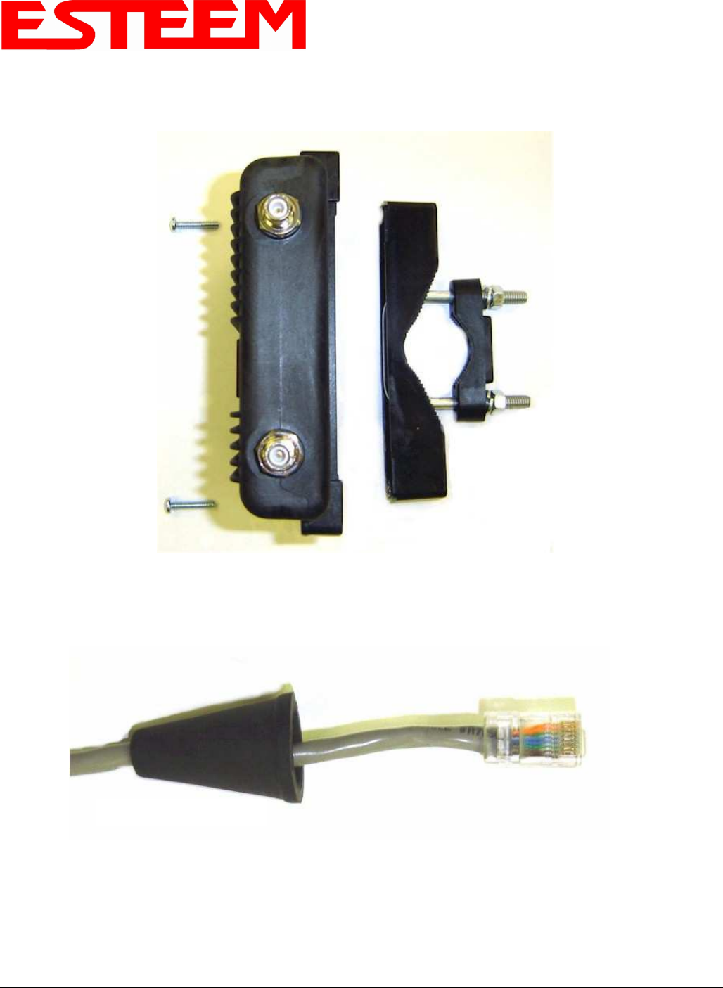
7. Assemble the outdoor rated CAT-5e Ethernet cable (Not Provided) with the supplied Ethernet Cable Boot (Figure 6).
8. Feed the CAT-5e Ethernet connector(s) through the Face Plate Cover and secure the Ethernet Cable Boot to the cover.
Reference Figure 7. NOTE: The Ethernet cable boot must be installed before the RJ-45 end is installed. If using the ESTeem
AA09.1 outdoor Ethernet cable, verify that the Ethernet cable boot end is routed toward the ESTeem 195Eg.
Figure 5: Pole Mount Connection to Case
(Heat Shield Removed for Detail)
Ethernet Cable Boot
Figure 6: Ethernet Cable Assembly
CHAPTER 8
ANTENNA SETUPS
Revised: 2 Jul 08 8-9 EST P/N AA107G
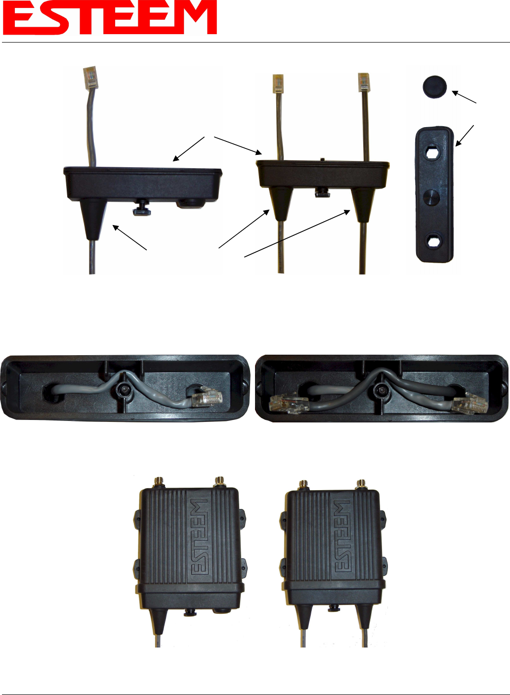
9. Route the CAT-5e Ethernet cable through the molded strain-relief fins in the Face Plate Cover (Figure 8) to secure the cable
and provide strain-relief for the connector. If a second Ethernet cable is installed, remove the second port cover and route
cable.
10. Plug the CAT-5e Ethernet cable to the Model 195Eg’s Ethernet port and secure the Face Plate Cover with the attached thumb
screw. Verify that the weatherproof seal on the Face Plate Cover is sealed against the outer rim of the Model 195Eg.
Reference Figure 9.
Figure 7: Ethernet Cable Routing
Figure 8: Face Plate Cover Strain Relief
Figure 9: Face Plate Cover Installed on ESTeem
Face Plate Cover
Ethernet Cable Boots
Second Port Cover
Remove for 2
nd
Cable
CHAPTER 8
ANTENNA SETUPS
Revised: 2 Jul 08 8-10 EST P/N AA107G
11. Attach the antenna connector boots as show in Figure 10 for either dual attached antennas or external antennas. You are now
ready to mount the ESTeem Model 195Eg
Caution: Outdoor mounting of the 195E requires the use of weatherproof boots. Improper installation
could result in radio failure.
Caution: Always mount the 195Eg vertically with the antenna ports on top.
Figure 10: Completed AA195PM Mounts
Direct Mount
Antenna Boots
Port A
EST Approved Direct Mount
Antenna Only
Port B
EST Approved External
Antenna With Factory
Installed Boot
Weather Proof Boot
NOTE: Remove Plastic
Connector Cover
Before Installation
Face Towards The
South
(North America)
CHAPTER 8
ANTENNA SETUPS
Revised: 2 Jul 08 8-11 EST P/N AA107G
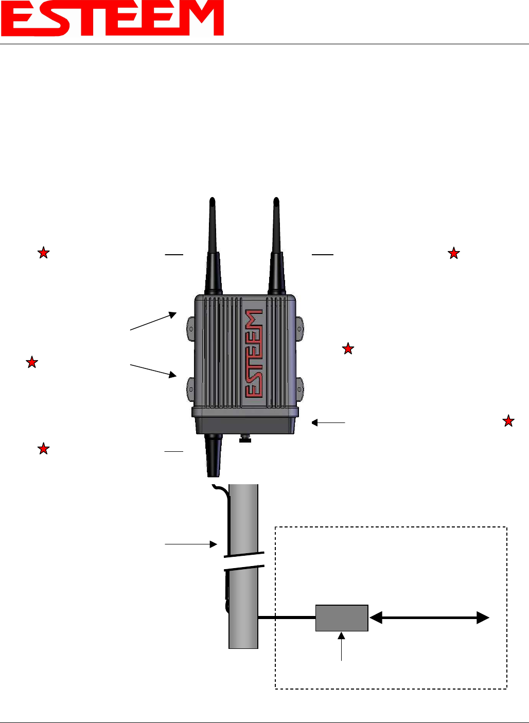
Model 195E Series with Direct Mount
Dual Diversity Antennas
Power Over
Ethernet Cable
Ethernet CAT-5e Cable
300 ft. maximum
Weatherproof Boot
Weatherproof Front Cover
Direct Pole Mount
Pole Mounting Kit
EST P/N AA195PM
Weatherproof BootWeatherproof Boot
POE Power Supply
EST P/N AA175
In Building
100-250 VAC
50-60 Hz
LAN
Interface
Pole Mounting
Brackets
(not shown)
Case Mount Omni-Directional
Dual Diversity Antennas
EST P/N AA01S or AA20DMEg
Caution: Always mount the 195Eg vertically with the antenna ports on top.
CHAPTER 8
ANTENNA SETUPS
Revised: 2 Jul 08 8-12 EST P/N AA107G
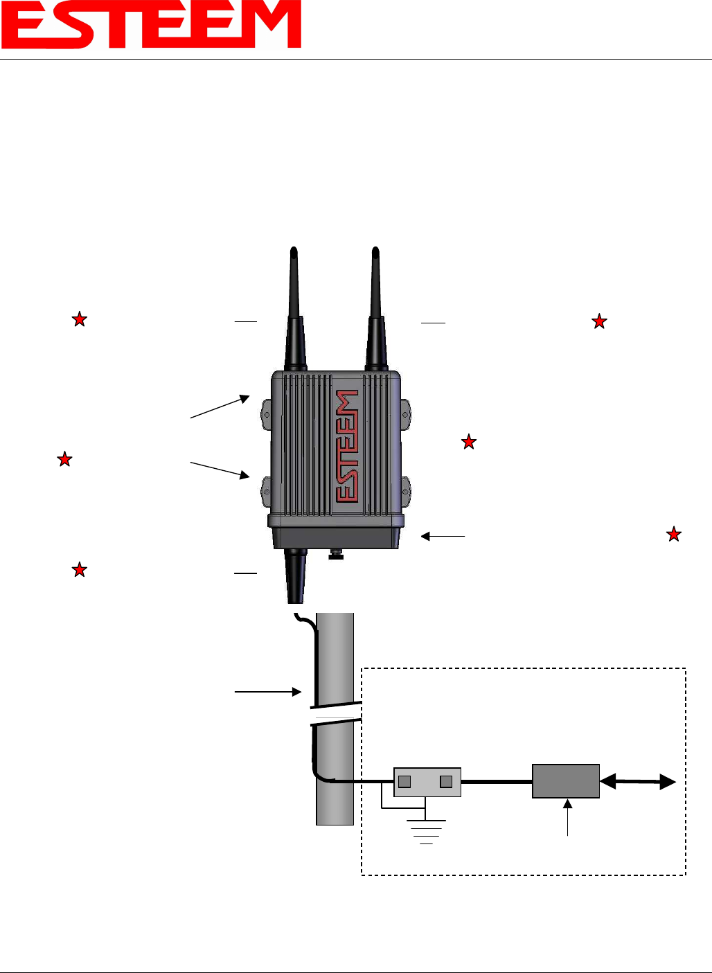
Caution: Always mount the 195Eg vertically with the antenna ports on top.
In Building
100-250 VAC
50-60 Hz
LAN
Interface
POE Power Supply
EST P/N AA175
Earth Ground
Ethernet Surge
Protection
EST P/N AA166
Model 195E Series with Direct Mount Dual
Diversity Antennas and Surge Protection
Power Over
Ethernet Cable
Ethernet CAT-5e Cable
300 ft. maximum
Weatherproof Boot
Weatherproof Front Cover
Direct Pole Mount
Pole Mounting Kit
EST P/N AA195PM
Weatherproof Boot
Weatherproof Boot
Pole Mounting
Brackets
(not shown)
Case Mount Omni-Directional
Dual Diversity Antennas
EST P/N AA01S or AA20DMEg
CHAPTER 8
ANTENNA SETUPS
Revised: 2 Jul 08 8-13 EST P/N AA107G
Caution: Always mount the 195Eg vertically with the antenna ports on top.
CHAPTER 8
ANTENNA SETUPS
Revised: 2 Jul 08 8-14 EST P/N AA107G
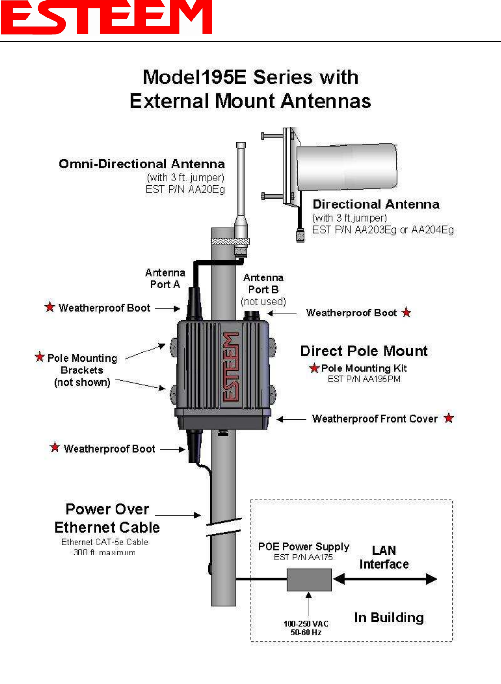
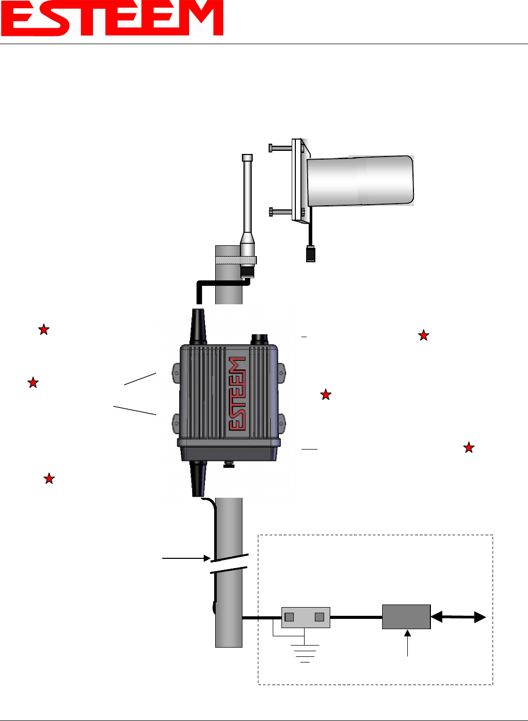
Model195E Series with External Mount
Antennas and Surge Protection
Shielded Outdoor
Ethernet Cable
EST P/N AA09.1
Ethernet CAT-5e Cable 300 ft.
maximum
Weatherproof Front Cover
Directional Antenna
(with 3 ft.jumper)
EST P/N AA203Eg or AA204Eg
Weatherproof Boot
Direct Pole Mount
Pole Mounting Kit
EST P/N AA195PM
Weatherproof Boot
Weatherproof Boot
In Building
100-250 VAC
50-60 Hz
LAN
Interface
Pole Mounting
Brackets
(not shown)
POE Power Supply
EST P/N AA175
Omni-Directional Antenna
(with 3 ft. jumper)
EST P/N AA20Eg
Antenna
Port B
(not used)
Antenna
Port A
Earth Ground
Ethernet Surge
Protection
EST P/N AA166
Caution: Always mount the 195Eg vertically with the antenna ports on top.
CHAPTER 8
ANTENNA SETUPS
Revised: 2 Jul 08 8-15 EST P/N AA107G
CHAPTER 8
ANTENNA SETUPS
Revised: 2 Jul 08 8-16 EST P/N AA107G
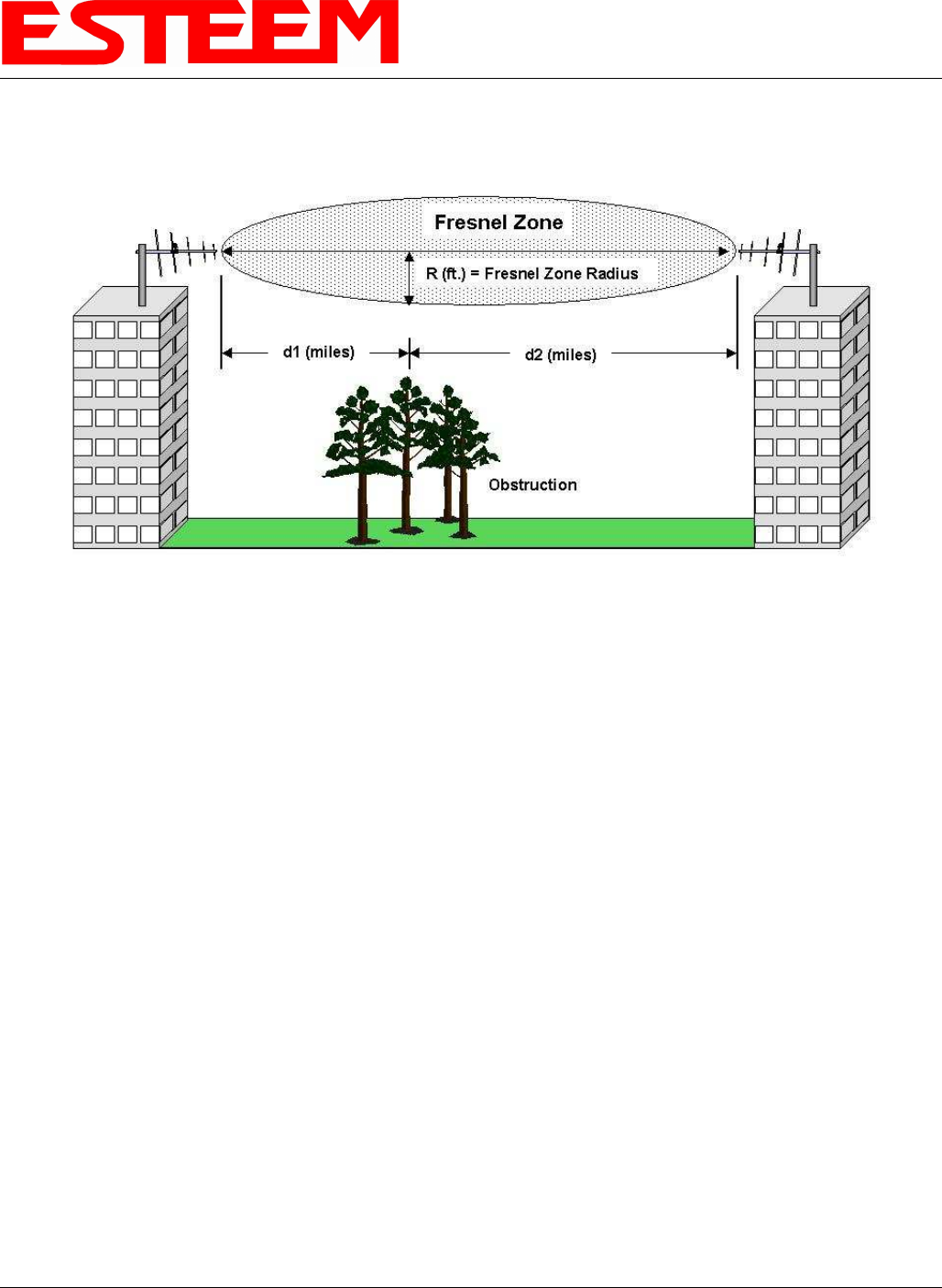
FRESNEL ZONE
The Fresnel zone shows the ellipsoid spread of the radio waves around the visual line-of-sight after they leave the antenna (see
figure above). This area must be clear of obstructions or the signal strength will be reduced due to signal blockage. Typically,
20% Fresnel Zone blockage introduces little signal loss to the link. Beyond 40% blockage, signal loss will become significant.
This calculation is based on a flat earth. It does not take into account the curvature of the earth. It is recommended for RF path
links greater than 7 miles to have a microwave path analysis done that takes the curvature of the earth and the topography of the
terrain into account.
Fresnel Zone Radius = 72.1 SQRT [(d1d2) / (F(d1 + d2)]
Units
Fresnel Zone Radius in feet.
d1 and d2 in statue miles
F in GHz