Electronic Systems Technology ESTEEM195EG-1 ESTEEM 195Eg User Manual Chapter 0 Front Cover 195Eg
Electronic Systems Technology ESTEEM 195Eg Chapter 0 Front Cover 195Eg
Contents
user manual ch 5a
CHAPTER 5
EXAMPLE CONFIGURATIONS
Revised: 23 Jan 08 5-1 EST P/N AA107G
PROGRAMMING EXAMPLES
In this chapter we will demonstrate how to program the ESTeem Model 195Eg for each of the operating modes. For a detailed
explanation of the modes, please refer to Chapter 1 of this manual. In the following examples we assume that the modems have
been initially configured for IP Address, Net Mask, etc. and are ready for programming from the Model 195Eg’s Web
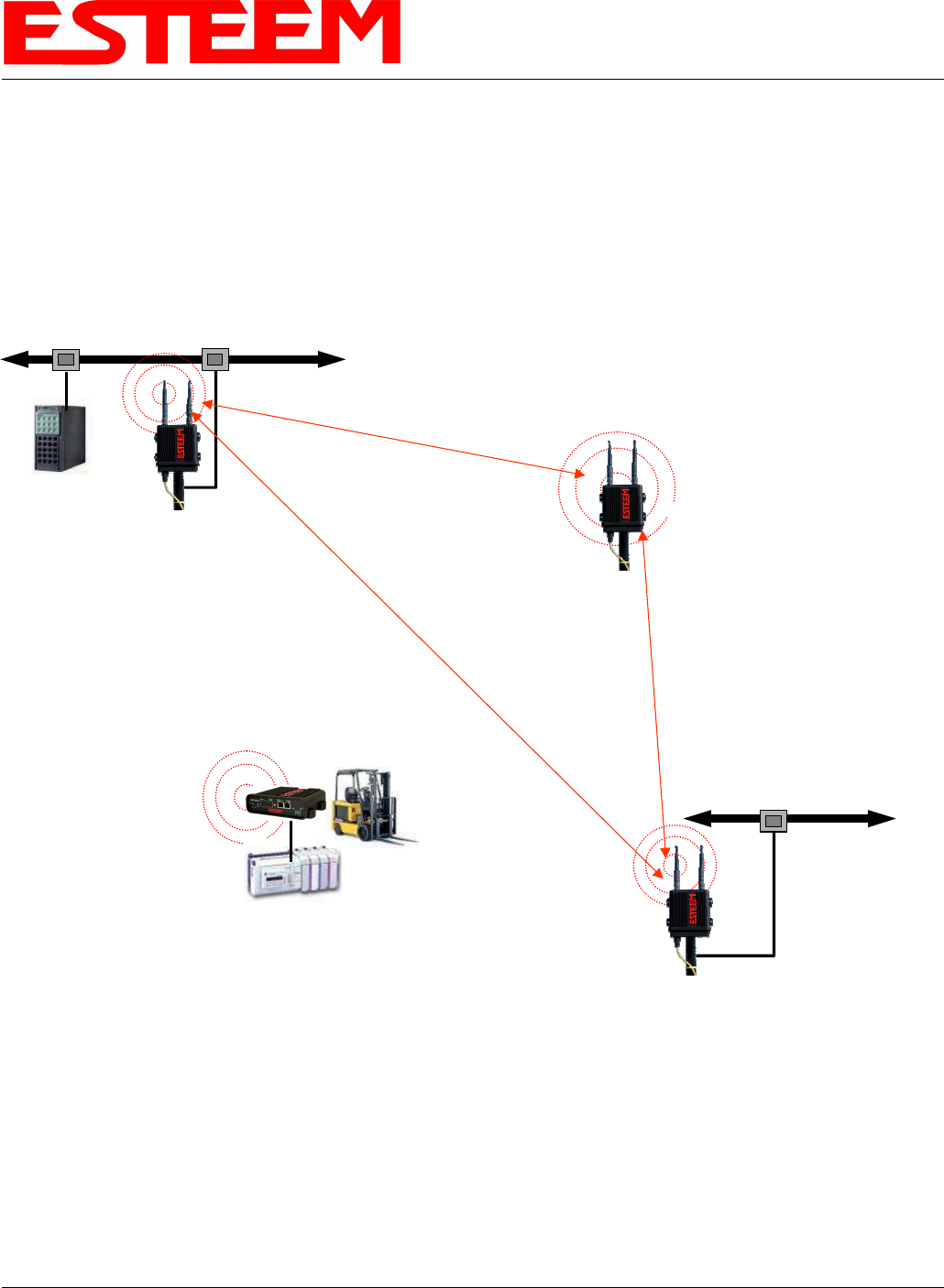
Configuration Manager’s Setup Menu. The first example network in Figure 1 consist of two wired Ethernet networks (Large Plant
LAN and Remote Building) that will be bridged together through a repeater site and have a direct backup pathway. This same
wireless mesh canopy will provide wireless access to the single PLC on the forklift (Example 4) and any other 802.11g or 802.11b
devices.
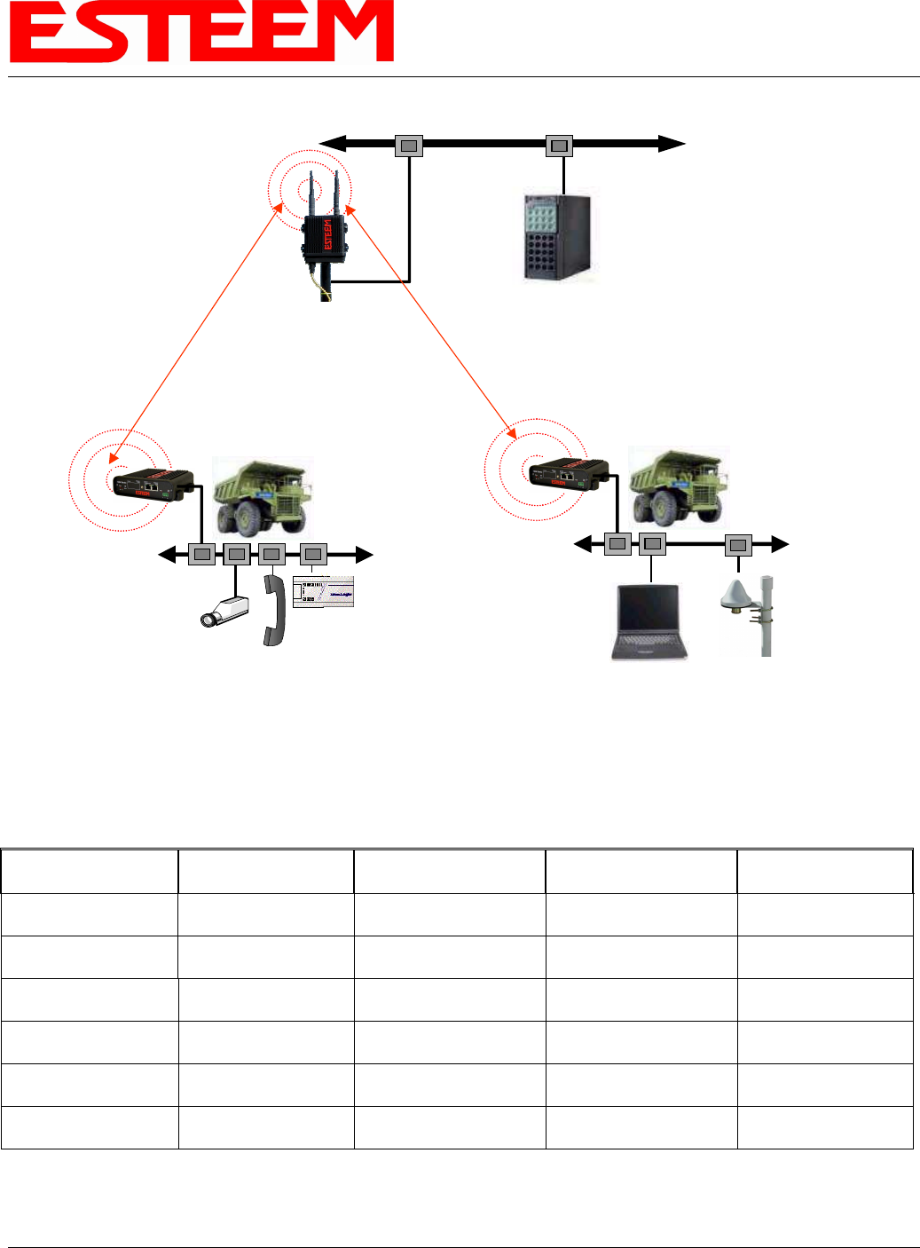
The second example network in Figure 2 show how to configure the Model 195Eg if multiple Ethernet devices are connected to a
single ESTeem Model 195Eg. A separate network address for the connected hardware is required and can be configured for fixed
or dynamic IP (DHCP) addressing. The use of multiple network addresses will require that a network router be programmed for
each of the remote devices. As we learned in Chapter 1 of this manual, the difference in the Station Router and the Station
Masquerade Mode will depend upon the required availability of accessing the connected Ethernet devices to the 195Eg. The
Station Router will allow devices on the Ethernet LAN to access these device and the Station Masquerade will not, very similar to a
firewall.
Access Point Router
with Repeater
Feature Enabled
10/100BaseT
HUB or Switch
Mobile
PLC
EtherStation
Mode
10/100BaseT
Access Point Bridge
with Repeater
Feature Enabled
Primary Repeater Path
Backup Repeater Path
Access Point Bridge
with Repeater
Feature Enabled
Mobile Vehicle
Single Ethernet Device
Example #4
S/N: 14004
Primary Repeater Path
Plant Network
Large Wired LAN
Example #1
S/N: E-14001
WLAN MAC=00:04:3F:00:09:01
Remote Building
Small Ethernet Wired LAN
Example #3
S/N: E-14003
WLAN MAC=00:04:3F:00:09:10
Stand-Alone Repeater Site
Example #2
S/N: E-14002
WLAN MAC= 00:04:3F:00:09:05
Network
Router
(Required)
Figure 1: Programming Example #1 Diagram
CHAPTER 5
EXAMPLE CONFIGURATIONS
Revised: 23 Jan 08 5-2 EST P/N AA107G
Documentation
The first step when configuring your wireless system will be to document each Model 195Eg used in the network. The following is
an example of the System Configuration Table (Chapter 2 – Starting Out) completed for the two example applications:
Modem_ID(Name)
/Operating Mode Serial Number IP Address Ethernet MAC WLAN MAC
Plant Network
AP_Router E-14001 Ethernet 172.17.2.1
Wireless 172.16.2.1 00:04:3f:00:09:02 00:04:3f:00:09:01
Repeater
AP_Bridge E-14002 Bridge 172.16.2.5 00:04:3f:00:09:06 00:04:3f:00:09:05
Remote Building
AP_Bridge E-14003 Bridge 172.16.2.10 00:04:3f:00:09:11 00:04:3f:00:09:10
Forklift
EtherStation E-14004 N/A 00:04:3f:00:09:21 00:04:3f:00:09:20
Truck #1
Station Router E-14005 Wireless 172.16.2.20
Ethernet 172.18.1.1 00:04:3f:00:09:26 00:04:3f:00:09:25
Truck #2
Station Masquerade E-14006 Wireless 172.16.2.30
Ethernet 172.19.1.1 00:04:3f:00:09:31 00:04:3f:00:09:30
Table 1: Example System Configuration Table
Mobile
PLC
Station Router Mode
Voice over IP
Mobile Vehicle #1
Multiple Ethernet Devices
Example #5
S/N: 14005
Mobile Vehicle #2
Multiple Ethernet Devices
Example #6
S/N: 14006
Station Masquerade Mode
Remote PC GPS
10/100BaseT
Access Point Bridge
with Repeater
Feature Enabled
Ethernet Wired LAN
Network
Router
(Required)
Figure 2: Programming Example #2 Diagram
CHAPTER 5
EXAMPLE CONFIGURATIONS
Revised: 23 Jan 08 5-3 EST P/N AA107G
Example 1 – Plant Network (Access Point Router with Repeater Enabled)
The ESTeem Model 195Eg configured as an Access Point Router will provide a separation between the larger Plant network and
the Ethernet devices connected on the wireless network. This mode of operation is most often used when connecting the wireless
system to a larger network to eliminate the Network broadcast traffic from entering the wireless system. If Ethernet devices on the
Plant network want to access Ethenet devices on the wireless network, a network router is required to resolve the IP conflict created
by having the wired and wireless networks on separate subnets.
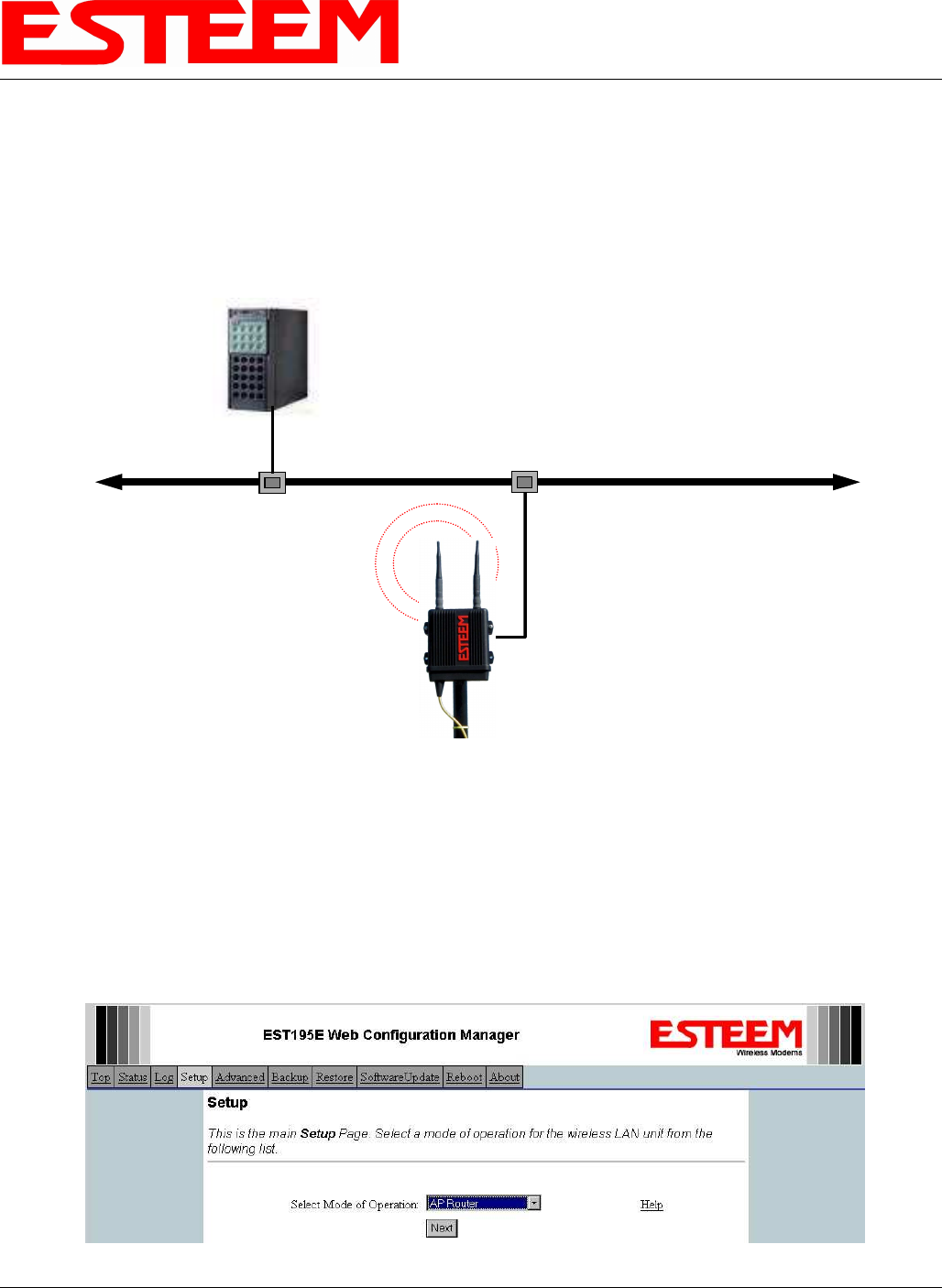
1. Access the ESTeem Web page using your computer’s Web Browser as per instructions in Chapter 4. Select Setup from the
menu items. From the Select Mode of Operation pull down box , select AP Router (Figure 4) and push the Next button
below the pull down box.
Access Point Router with
Repeater Feature Enabled
10/100BaseT
HUB or Switch
Plant Network
Large Wired LAN
Example #1
S/N: E-14001
Ethernet MAC = 00:04:3F:00:09:02
WLAN MAC=00:04:3F:00:09:01
Network Router (Required)
IP Address 172.17.1.1
Netmask 255.255.0.0
Routes for 172.16.X.X network use
gateway 172.17.2.1
Note: Ethernet and
Wireless Networks Must
Be on Separate Subnets
Wired Ethernet Address 172.17.X.X
Gateway Address = 172.17.1.1
Ethernet IP Address = 172.17.2.1
Netmask = 255.255.0.0
Wireless IP Address = 172.16.2.1
Netmask = 255.255.0.0
Default Route = 172.17.1.1
Wireless Addresses 172.16.X.X
Gateway (Route) Address = 172.16.2.1
Figure 3: Access Point Router IP Addressing Example
Figure 4: Access Point Router Setup Screen
CHAPTER 5
EXAMPLE CONFIGURATIONS
Revised: 23 Jan 08 5-4 EST P/N AA107G
Note: Throughout the Configuration Manager are Help Screens that can accessed for further information on each item.
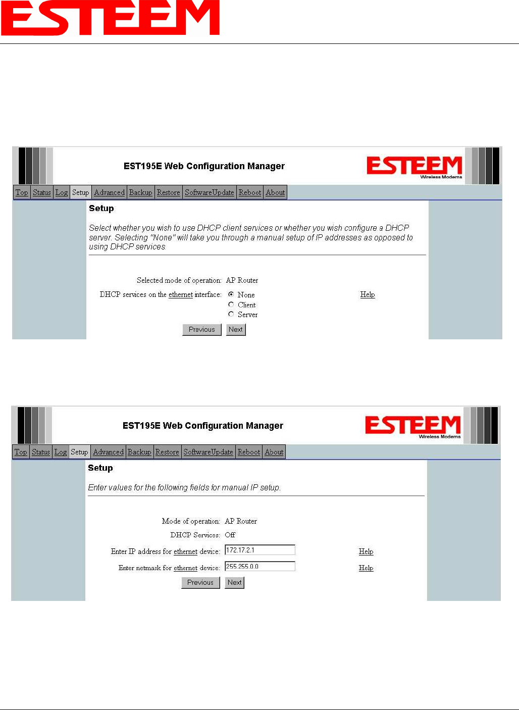
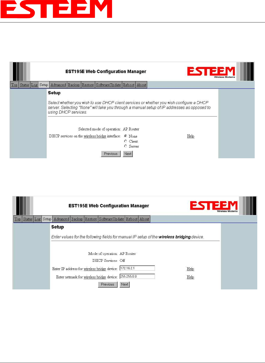
2. Select if you want to use client or server Dynamic Host Configuration Protocol (DHCP) for the Ethernet device. If you want to
enter a static IP address for the Model 195Eg, select Off and press the Next button. For our example, we have fixed IP
addresses and will select Off. For more information on the operation and configuration of DHCP, please refer to Appendix C –
Interface Ports. Reference Figure 5.
3. Refer to the site documentation (Table 1) and enter the IP Address and IP Netmask for the Model 195Eg on the Ethernet port.
Reference Figure 6.
Figure 5: DHCP Ethernet Port
Figure 6: Ethernet IP Addressing
CHAPTER 5
EXAMPLE CONFIGURATIONS
Revised: 23 Jan 08 5-5 EST P/N AA107G
4. Select if you want to use client or server Dynamic Host Configuration Protocol (DHCP) for the Wireless device. If you want to
enter a static IP address for the Model 195Eg, select Off and press the Next button. For our example, we have fixed IP
addresses and will select Off. For more information on the operation and configuration of DHCP, please refer to Appendix C –
Interface Ports. Reference Figure 7.
5. Refer to the site documentation (Table 1) and enter the IP Address and IP Netmask for the Model 195Eg on the Wireless port.
Reference Figure 8.
Figure 7: DHCP Wireless Port
Figure 8: Wireless IP Address
CHAPTER 5
EXAMPLE CONFIGURATIONS
Revised: 23 Jan 08 5-6 EST P/N AA107G
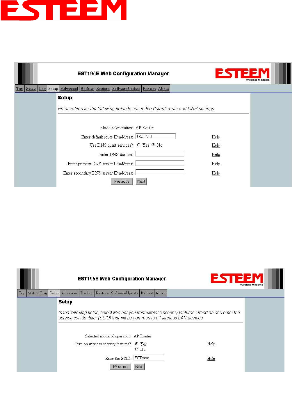
6. Enter the default route (Gateway) address for the network. This AP Router 195Eg will use the Network Router for address
resolution (Figure 3). Enter the IP address for the Network Router and any DNS server information. If you are not connecting
the Model 195Eg to the Internet, leave blank and press the Next button. Figure 9.
7. Select Yes if you will be using security for client access to your wireless network (recommened).
NOTE: The setting of this security level is ONLY for client access to the Model 195Eg. The security of the Bridge
communication between the Model 195Eg’s is separate and will be configured during the repeater configuration.
Enter the SSID for your 802.11g network. The SSID is the unique identification for your wireless network and all 802.11g
devices that share a wireless network MUST have the same SSID code. This identification code is case sensitive and must
NOT contain spaces. Reference Figure 10.
Figure 9: Wireless Security Level Settings
Figure 10: WEP Key Entry
CHAPTER 5
EXAMPLE CONFIGURATIONS
Revised: 23 Jan 08 5-7 EST P/N AA107G
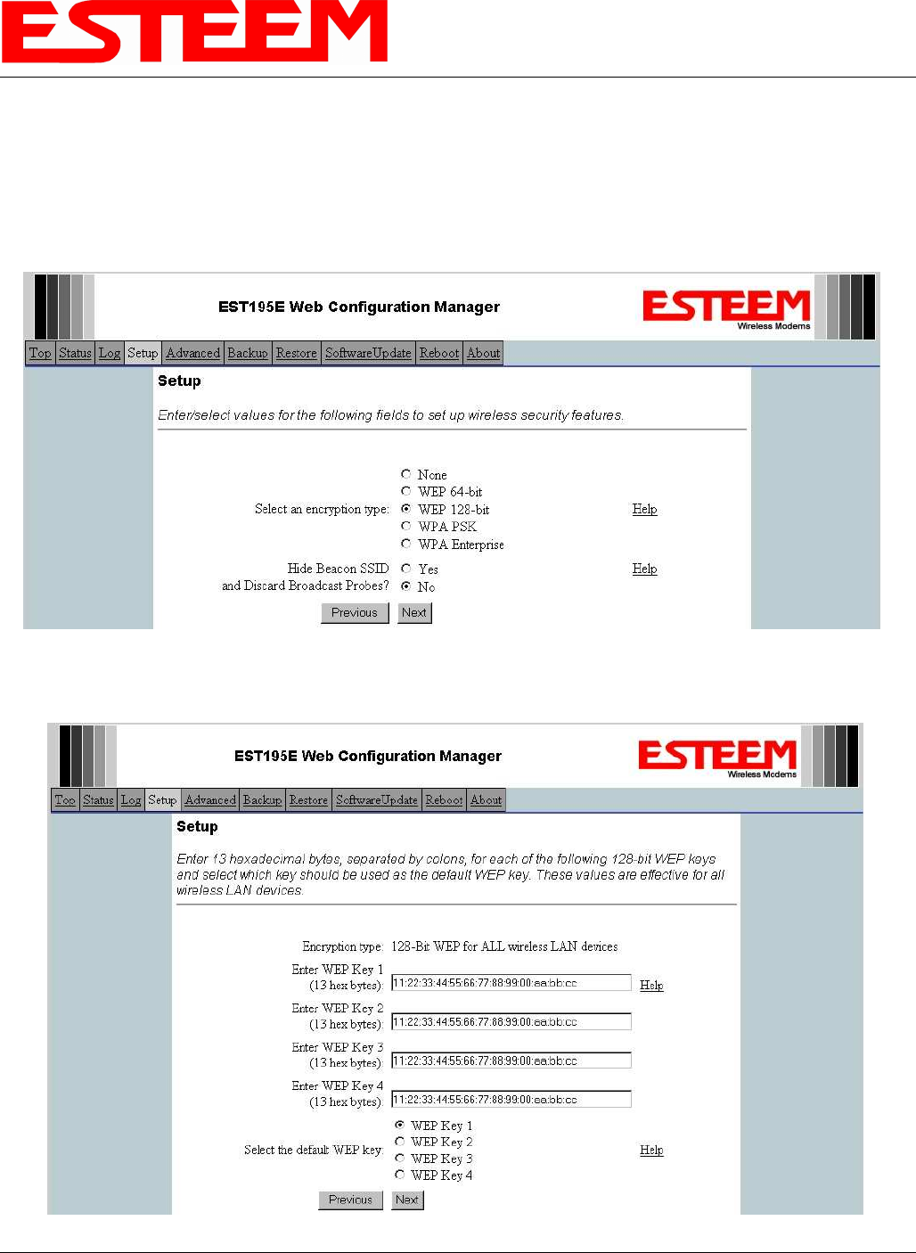
8. Select the encryption level for the wireless client access to the network. For further information on the different levels of
security, please refer to Appendix E – Security of this User’s Manual. If you would like to hide the SSID from broadcasting
from the Access Point and would like to discard the broadcast probes select Yes. If Yes is selected the Model 195Eg will no
longer send out periodic SSID radio beacons that can be identified with 802.11b network scanning software. The users of the
network will have to know the SSID to enter the network and security is increased, but if you want the SSID to be broadcast to
the network for easy identification then select No. In our example, we will be using mobile clients with 128 bit WEP.
Reference Figure 11.
9. Enter the WEP key values for your application that will be used by all devices on the wireless network. Reference Figure 12.
Figure 11: Security Selection
Figure 12: WEP Key Input Screen
CHAPTER 5
EXAMPLE CONFIGURATIONS
Revised: 23 Jan 08 5-8 EST P/N AA107G
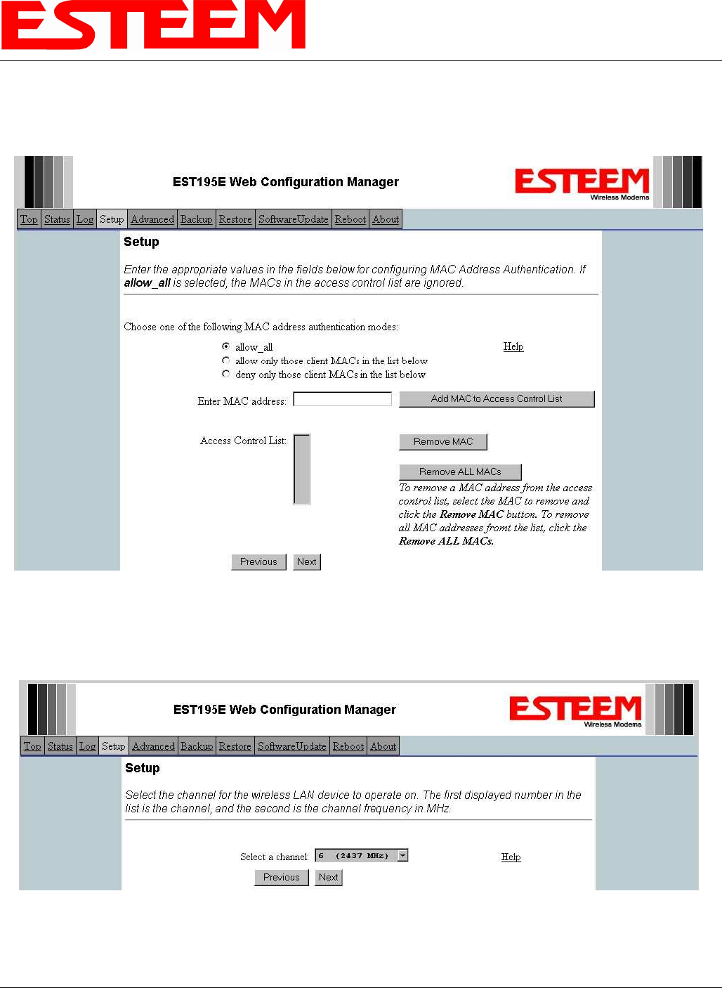
10. Enter the values for the Access Control List (ACL). This is a configurable MAC filter that can be set to allow or deny specific
wireless MAC address to the network. This feature is further explained in Appendix E – Security. In our example we will not
use the ACL. Reference Figure 13.
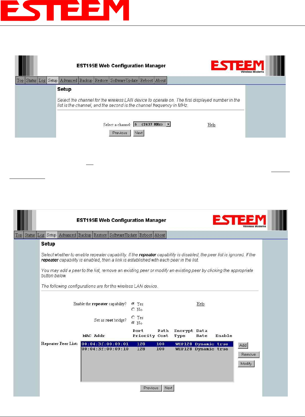
11. Select the frequency channel of operation. All Access Points in the same Repeater Peer network need to be on the same radio
frequency channel. See Appendix D – Radio Configuration for help in selecting the frequency channel. Reference Figure 14.
Figure 13: Access Control List Settings
Figure 14: Radio Channel Selection
CHAPTER 5
EXAMPLE CONFIGURATIONS
Revised: 23 Jan 08 5-9 EST P/N AA107G
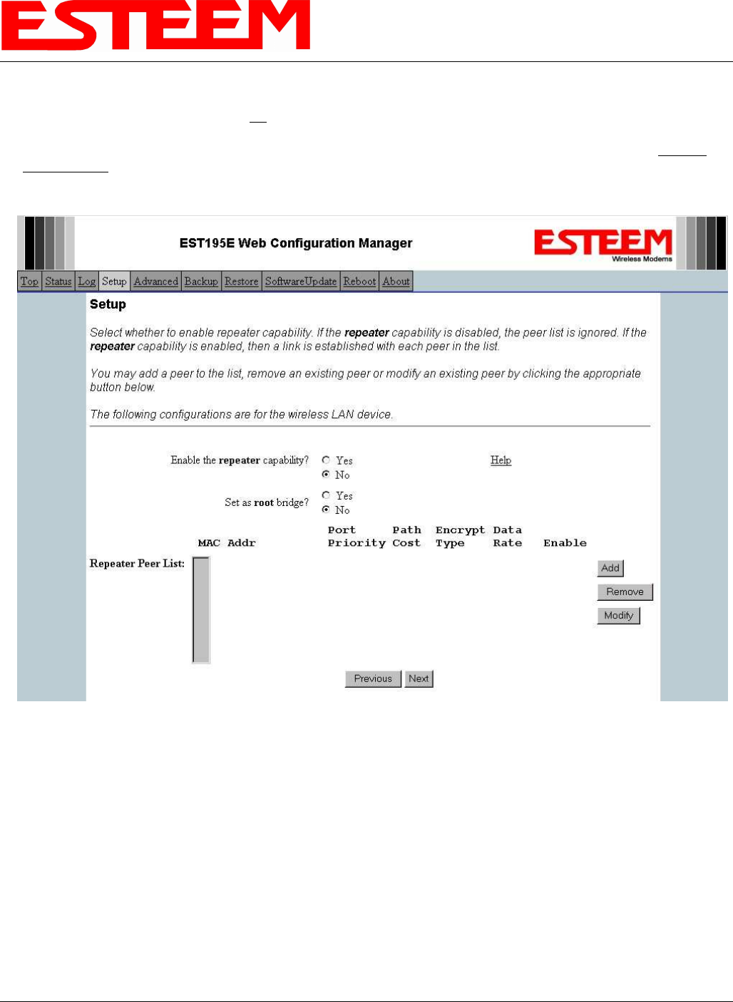
12. The Repeater Peer Table (Figure 15) identifies which Model 195Eg’s will bridge wireless Ethernet communication. Only other
Access Point Repeaters need to be listed not the Model 195Eg’s in client modes. Multiple links to the same destination will
provide a backup pathway (Mesh Network) if the primary pathway is lost. Looking at the system layout in Figure 1, both the
repeater site and the direct link will be listed. Using the System Configuration Table (Table 1) as a guide, enter the Wireless
(WLAN) MAC address for the 195Eg’s that will communicate with the Access Point Router (Example 1) starting with the
primary repeater path through the stand-alone repeater.
The communication link through repeater site is the best radio path from the Plant Network to the Remote Building and we
want this link to be the primary repeater route. The 195Eg follows the same networking “rules” as any other Ethernet device
and if we made no changes to the default path cost of 100 the lowest path cost would be directly to the Remote Building (Direct
= 100, Repeater = 200 (100+100)). To configure the 195Eg to select the repeater as the primary radio path, the direct link’s
path cost must be greater than the cost through the repeater link (any number greater than 200). We will set the path cost at 201
for the direct link, making the repeater link a lower path cost and thus the primary pathway. Press the Add button to enter the
first repeater link to the Repeater Peer List and Figure 16 will be displayed.
Note: For a more complete description on configuring repeater routes, see Chapter 6 – Repeating Features.
Figure 15: Blank Repeater Table
CHAPTER 5
EXAMPLE CONFIGURATIONS
Revised: 23 Jan 08 5-10 EST P/N AA107G
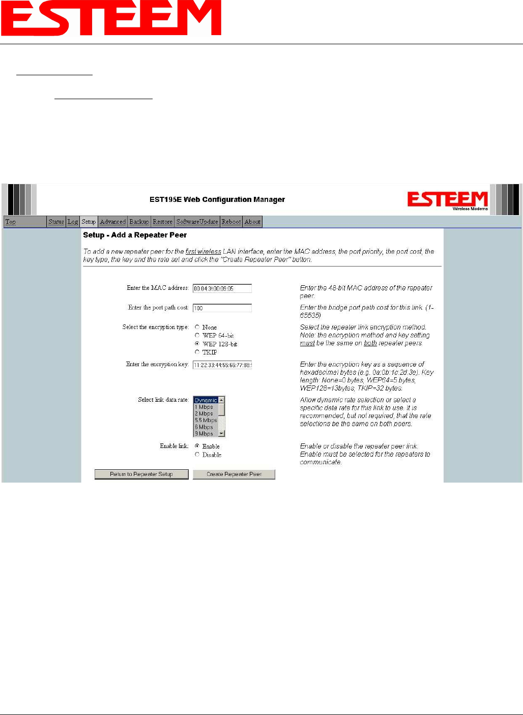
First Repeater Link -
Enter the Wireless (WLAN) MAC address of the stand-alone repeater site and the path cost for this link will stay at the default
value at 100. Select the level of Encryption for this communication link. The encryption levels for the repeater peer link must
be the same on both sides, but is completely independent from the Encryption level for the client access to the network. For
consistency in our example, we will also use 128-Bit WEP Encryption for the Repeater Peer link. Setting the link data rate to
Dynamic will allow all data rates from 1 Mbps to 54 Mbps to be used. Verify the Repeater Link is set to Enable and press the
Create Repeater Peer Button.
Figure 16: First (Primary) Repeater Link
CHAPTER 5
EXAMPLE CONFIGURATIONS
Revised: 23 Jan 08 5-11 EST P/N AA107G
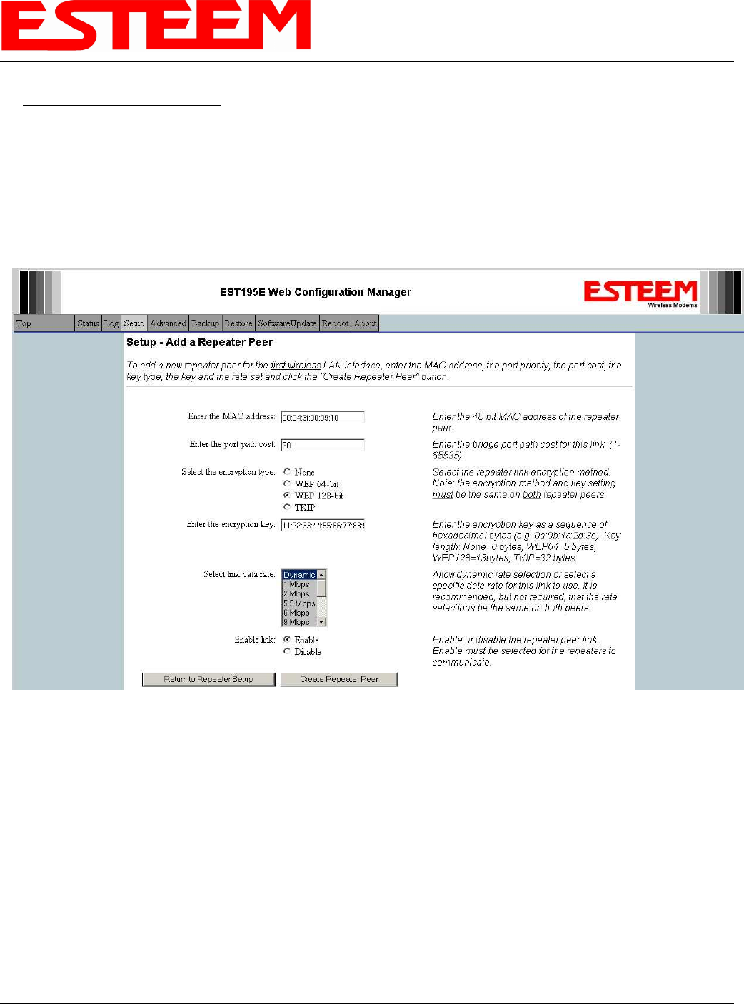
Second Repeater Link (Direct Path) -
Press the Add button a second time (Figure15) and Figure 17 will be displayed. Enter the Wireless (WLAN) MAC address of
the Remote Building and set the path cost for this link to a value of 201. Select the level of Encryption for this communication
link. The encryption levels for the repeater peer link must be the same on both sides, but is completely independent from the
Encryption level for the client access to the network. For consistency in our example, we will also use 128-Bit WEP Encryption
for the Repeater Peer link. Setting the link data rate to Dynamic will allow all data rates from 1 Mbps to 54 Mbps to be used.
Verify the Repeater Link is set to Enable and press the Create Repeater Peer Button.
Figure 17: Second (Backup) Repeater Link
CHAPTER 5
EXAMPLE CONFIGURATIONS
Revised: 23 Jan 08 5-12 EST P/N AA107G
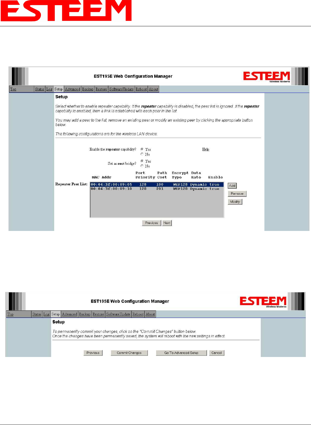
Figure 18 displays the complete repeater peer list with both repeater peer entries. Set Enable repeater capability to Yes and to
both repeater paths. This Access Point Router 195Eg is also the primary data path for all Ethernet traffic on the network and
will also need to be configured as the Root Bridge. Press the Next button to continue.
13. Figure 19 will be displayed. If no further changes are necessary to the modem, you can commit the changes that will then be
saved and the modem rebooted.
Figure 18: Completed Repeater Peer List
Figure 19: Commit Changes
CHAPTER 5
EXAMPLE CONFIGURATIONS
Revised: 23 Jan 08 5-13 EST P/N AA107G
Example 2 – Stand Alone Repeater (Access Point Bridge with Repeater Enabled)
Review the example diagram, Figure 1, and locate the 195Eg marked as Example #2. This ESTeem is being used by two other
Model 195Eg’s as a repeater but is not connected to an Ethernet network. This modem should be configured for Access Point
Bridge mode.
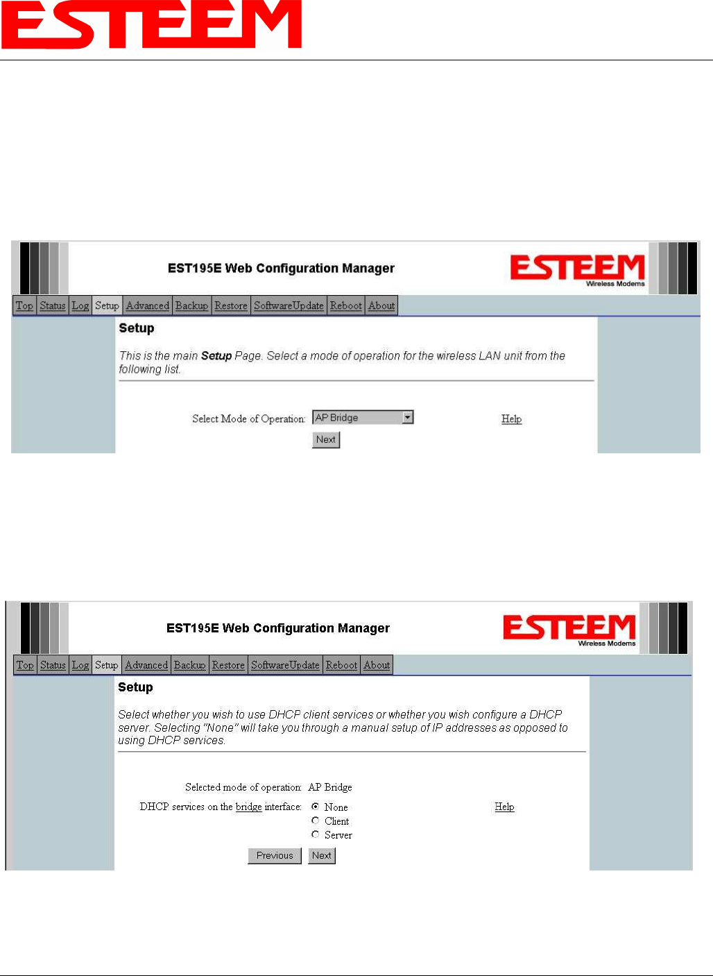
1. Access the ESTeem Web page using your computer’s Web Browser as per instructions in Chapter 4. Select Setup from the
menu items. From the Select Mode of Operation pull down box , select AP Bridge (Figure 20) and push the Next button below
the pull down box.
2. Select if you want to use client or server Dynamic Host Configuration Protocol (DHCP) for the 195Eg. If you want to enter a
static IP address for the Model 195Eg, select Off and press the Next button. For our example, we have fixed IP addresses and
will select Off. Reference Figure 21.
Figure 20: Access Point Bridge
Figure 21: DHCP Configuration
CHAPTER 5
EXAMPLE CONFIGURATIONS
Revised: 23 Jan 08 5-14 EST P/N AA107G
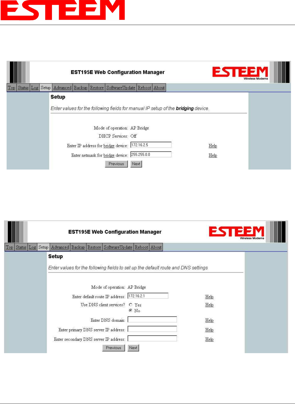
3. Enter the bridge IP Address and IP Netmask for the Model 195Eg. You will notice that for the 195Eg in AP Bridge mode only
a single IP address in entered. Both the ethernet IP and wireless IP addresses will be the same in the bridge mode. Reference
Figure 22.
4. Enter the default route (Gateway) address for the network. For Ethernet devices on the wireless network (IP 172.16.X.X – See
Figure 3), the AP Router 195Eg will be the gateway. Enter the wireless IP address for the AP Router 195Eg (configured in
Example 1) and any DNS server information. If you are not connecting the Model 195Eg to the Internet, leave blank and press
the Next button. Figure 23.
Figure 22: Bridge IP Addresses
Figure 23: Default Route (Gateway) and DNS Configuration
CHAPTER 5
EXAMPLE CONFIGURATIONS
Revised: 23 Jan 08 5-15 EST P/N AA107G
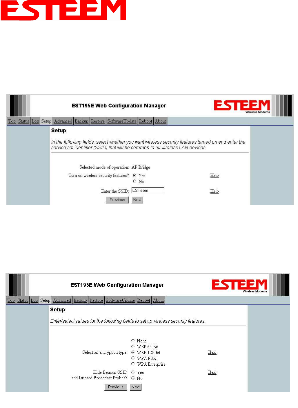
5. Select Yes if you will be using security for your wireless network (recommened).
NOTE: The setting of this security level is ONLY for client access to the Model 195Eg. The security of the Bridge
communication between the Model 195Eg’s is separate and will be configured during the repeater configuration.
Enter the SSID for your 802.11g network. The SSID is the unique identification for your wireless network and all 802.11g
devices that share a wireless network MUST have the same SSID code. This identification code is case sensitive and must
NOT contain spaces. Reference Figure 24.
6. Select the encryption level for client access to the wireless network. For further information on the different levels of security,
please refer to Appendix E – Security of this User’s Manual. If you would like to hide the SSID from broadcasting from the
Access Point select Yes. If Yes is selected the Model 195Eg will not send out periodic SSID radio beacons that can be
identified with 802.11b network scanning software. The users of the network will have to know the SSID to enter the network
and security is increased, but if you want the SSID to be broadcast to the network for easy identification then select No. The
195Eg can also be configured to discard the probe requests from 802.11g clients. If desired, set Discard Broadcast Probes to
Yes. In our example, we will be using mobile clients with 128 bit WEP. Reference Figure 25.
Figure 24: Security and SSID Configuration
Figure 25: Encryption Level Selection
CHAPTER 5
EXAMPLE CONFIGURATIONS
Revised: 23 Jan 08 5-16 EST P/N AA107G
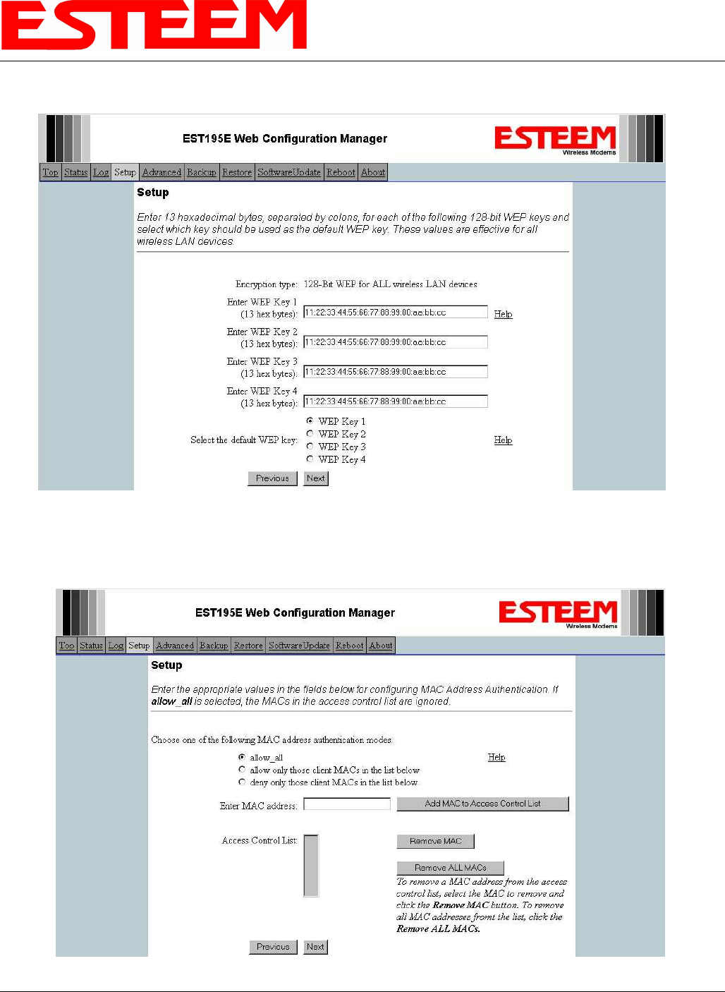
7. Enter the WEP key values for your application that will be used by all devices on the wireless network. Reference Figure 26.
8. Enter the values for the Access Control List (ACL). This is a configurable MAC filter that can be set to allow or deny specific
wireless MAC address to the network. This feature is further explained in Appendix E – Security. In our example we will not
use the ACL. Reference Figure 27.
Figure 26: WEP Key Entry
Figure 27: ACL Configuration
CHAPTER 5
EXAMPLE CONFIGURATIONS
Revised: 23 Jan 08 5-17 EST P/N AA107G
9. Select the frequency channel of operation. All Access Points in the same Repeater Peer network need to be on the same radio
frequency channel. See Appendix D – Radio Configuration for help in selecting the frequency channel. Reference Figure 28.
10. The Repeater Peer Table identifies which Model 195Eg’s will bridge wireless Ethernet communication. Only other Access
Point Repeaters need to be listed not the Model 195Eg’s in client modes. Looking at the system layout in Figure 1 and what we
discussed in Example 1, both the Plant Network’s 195Eg and the Remote Building’s 195Eg will be listed by their wireless
(WLAN) MAC (Figure 29). There is only a single radio connection path to the other two 195Eg’s in the network. The path
cost only effects redundant links in the network (not applicable to the repeater) and will be left at default. Enter the WLAN
MAC addresses for the other two Access Points and press the Next button to continue.
11. Select Commit Changes to write the programming to Flash memory and reboot the Model 195Eg. When the reboot process has
completed (approximately 30 seconds) the modem will be ready to place in operation.
Figure 28: Channel Configuration
Figure 29: Repeater Configuration