Electronic Systems Technology ESTEEM195EG-1 ESTEEM 195Eg User Manual Chapter 0 Front Cover 195Eg
Electronic Systems Technology ESTEEM 195Eg Chapter 0 Front Cover 195Eg
Contents
user manual ch 5b
CHAPTER 5
EXAMPLE CONFIGURATIONS
Revised: 23 Jan 08 5-18 EST P/N AA107G
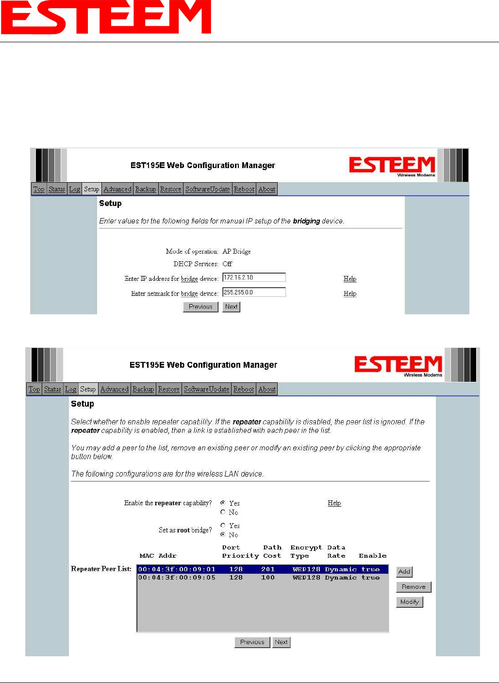
Example 3 – Remote Building (Access Point Bridge with Repeater Enabled)
1. Review Example #1 diagram (Figure 1) and locate the 195Eg marked as Example 3. This ESTeem is connected to a Remote
Building network that will be bridged to the Plant network through the Access Point Router (Example #1) via the repeater. This
modem should be configured for Access Point Bridge mode and the configuration for this 195Eg will be identical to Example 2
except that the IP addressing and the Repeater Peer table. You would follow all steps 1-11 in Example 2 to configure this
195Eg also but Figures 31 & 32 will show the changes.
Figure 31: Example 3 Bridge IP Address
Figure 32: Example 3 Repeater Routing Table
CHAPTER 5
EXAMPLE CONFIGURATIONS
Revised: 23 Jan 08 5-19 EST P/N AA107G
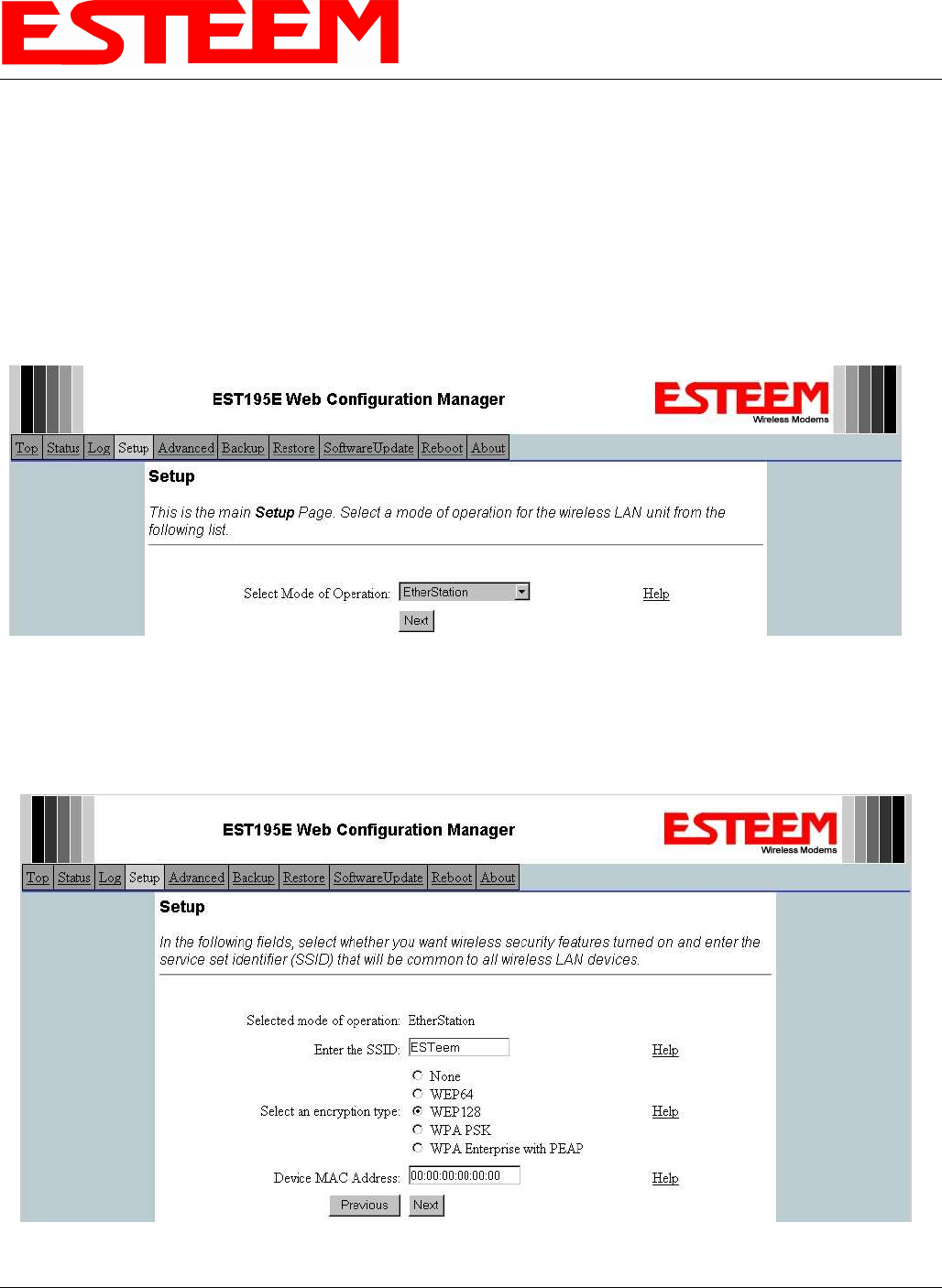
Example 4 – Mobile Vehicle with Single Ethernet Device (EtherStation Mode)
Review the Example Diagram #1 (Figure 1) and locate the 195Eg marked as Example 4. This ESTeem is connected to a single
Ethernet device in a mobile application and will be configured for EtherStation mode. In this mode the 195Eg will gain access to
the wireless Ethernet canopy created by the three Access Points (Examples 1-3), but will be emulating the MAC address for the
connected Ethernet device and will no longer have an IP address in the network. To reprogram the 195Eg after configuration in
EtherStation mode requires the ESTeem Discovery Utility or direct connection to the RS-232 port.
1. Access the ESTeem Web page using your computer’s Web Browser as per instructions in Chapter 4. Select Setup from the
menu items. From the Select Mode of Operation pull down box , select EtherStation (Figure 33) and push the Next button
below the pull down box.
2. Enter the SSID for you 802.11g network. The SSID is the unique identification for your wireless network and all 802.11g
devices that share a wireless network MUST have the same SSID code. This identification code is case sensitive and must
NOT contain spaces. Select the encryption level for the wireless network to match the level of the Access Point canopy. Enter
the MAC address of the connected Ethernet device. Reference Figure 34.
Figure 33: EtherStation Selection
Figure 34: SSID and Device MAC Input
CHAPTER 5
EXAMPLE CONFIGURATIONS
Revised: 23 Jan 08 5-20 EST P/N AA107G
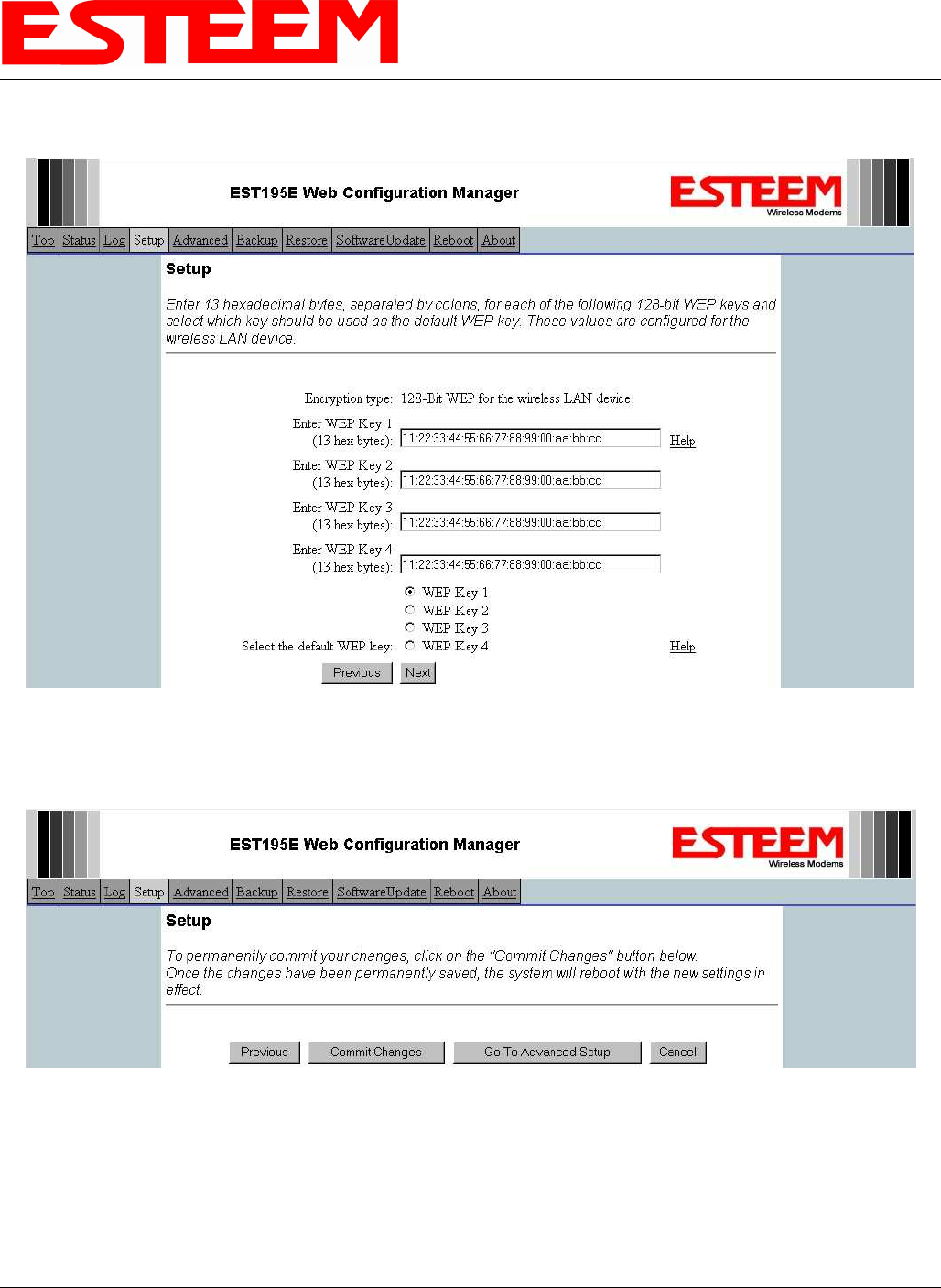
3. Enter the WEP key values for your application that will be used by all devices on the wireless network. Reference Figure 35.
4. Select Commit Changes to write the programming to Flash memory and reboot the Model 195Eg. When the reboot process has
completed (approximately 30 seconds) the modem will be ready to place in operation. Reference Figure 36.
Figure 35: WEP Key Input
Figure 36: EtherStation Selection
CHAPTER 5
EXAMPLE CONFIGURATIONS
Revised: 23 Jan 08 5-21 EST P/N AA107G
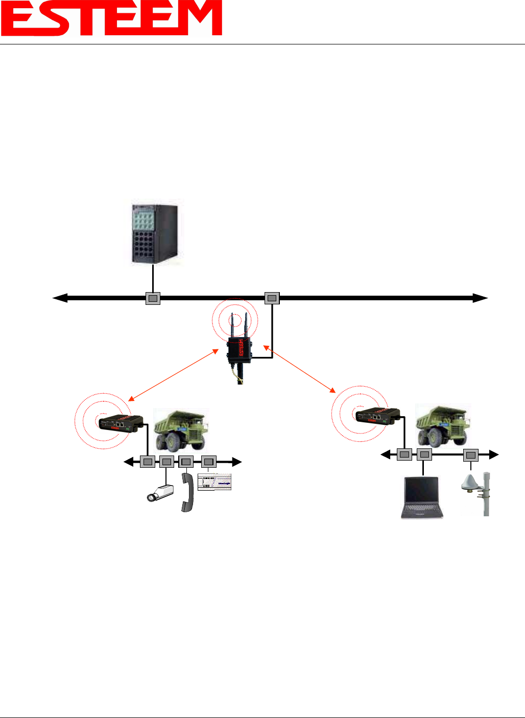
Example 5 – Mobile Vehicle #1 (Station Router)
Review the Example Diagram #2 (Figure 2) and locate the 195Eg marked as Example 5. This ESTeem is connected to multiple
Ethernet devices in a mobile application and will be configured Station Router mode. In this mode the 195Eg’s will gain access to
the wireless Ethernet canopy created by the Access Point and act as the router between the devices connected to the Ethernet port
and wireless network. Each of these networks will require a unique subnet to operate. If Ethernet devices on the wired LAN
network want to access Ethenet devices on the Station Router 195Eg, a network router is required on the wired LAN to resolve the
IP conflict created by having the wired and wireless networks on separate subnets (Figure 37).
HUB or Switch
Network Router (Required)
IP Address 172.16.1.6
Netmask 255.255.0.0
Routes for 172.18.X.X network use
gateway 172.16.2.20
Routes for 172.19.X.X network use
gateway 172.16.2.30
Note: Wireless Networks and
Station Modes Must Be on
Separate Subnets
Bridge IP Address = 172.16.1.1
Netmask = 255.255.0.0
Default Route = 172.16.1.6
Mobile
PLC
Station Router Mode
Voice over IP
Mobile Vehicle #1
Multiple Ethernet Devices
Example #5
S/N: 14005
Netmask 255.255.0.0
Wireless IP Address
172.16.2.20
Ethernet IP Address
172.18.1.1
Gateway(Route)
172.16.1.6
Mobile Vehicle #2
Multiple Ethernet Devices
Example #6
S/N: 14006
Netmask 255.255.0.0
Wireless IP Address
172.16.2.30
Ethernet IP Address
172.19.1.1
Gateway(Route)
172.16.1.6
Station Masquerade Mode
Remote PC GPS
Access Point Bridge with
Repeater Feature Enabled
Connected Ethernet Devices
172.18.X.X
Gateway (Route) = 172.18.1.1
Connected Ethernet Devices
172.19.X.X
Gateway (Route) = 172.19.1.1
Figure 37: Station Router IP Addressing Diagram
CHAPTER 5
EXAMPLE CONFIGURATIONS
Revised: 23 Jan 08 5-22 EST P/N AA107G
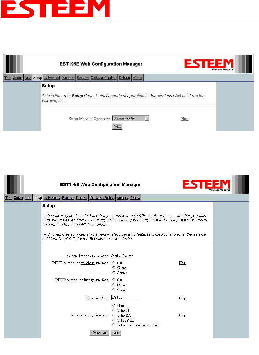
1. Access the ESTeem Web page using your computer’s Web Browser as per instructions in Chapter 4. Select Setup from the
menu items. From the Select Mode of Operation pull down box , select Station Router (Figure 38) and push the Next button
below the pull down box.
2. Select Yes if you would like to use DHCP services on either the wireless or ethernet connections. Enter the SSID for you
802.11g network. The SSID is the unique identification for your wireless network and all 802.11g devices that share a wireless
network MUST have the same SSID code. This identification code is case sensitive and must NOT contain spaces. Select the
encryption level for the wireless network to match the level of the Access Point canopy. Reference Figure 39.
Figure 38:Station Router Selection
Figure 39:DHCP, SSID and Encryption Settings
CHAPTER 5
EXAMPLE CONFIGURATIONS
Revised: 23 Jan 08 5-23 EST P/N AA107G
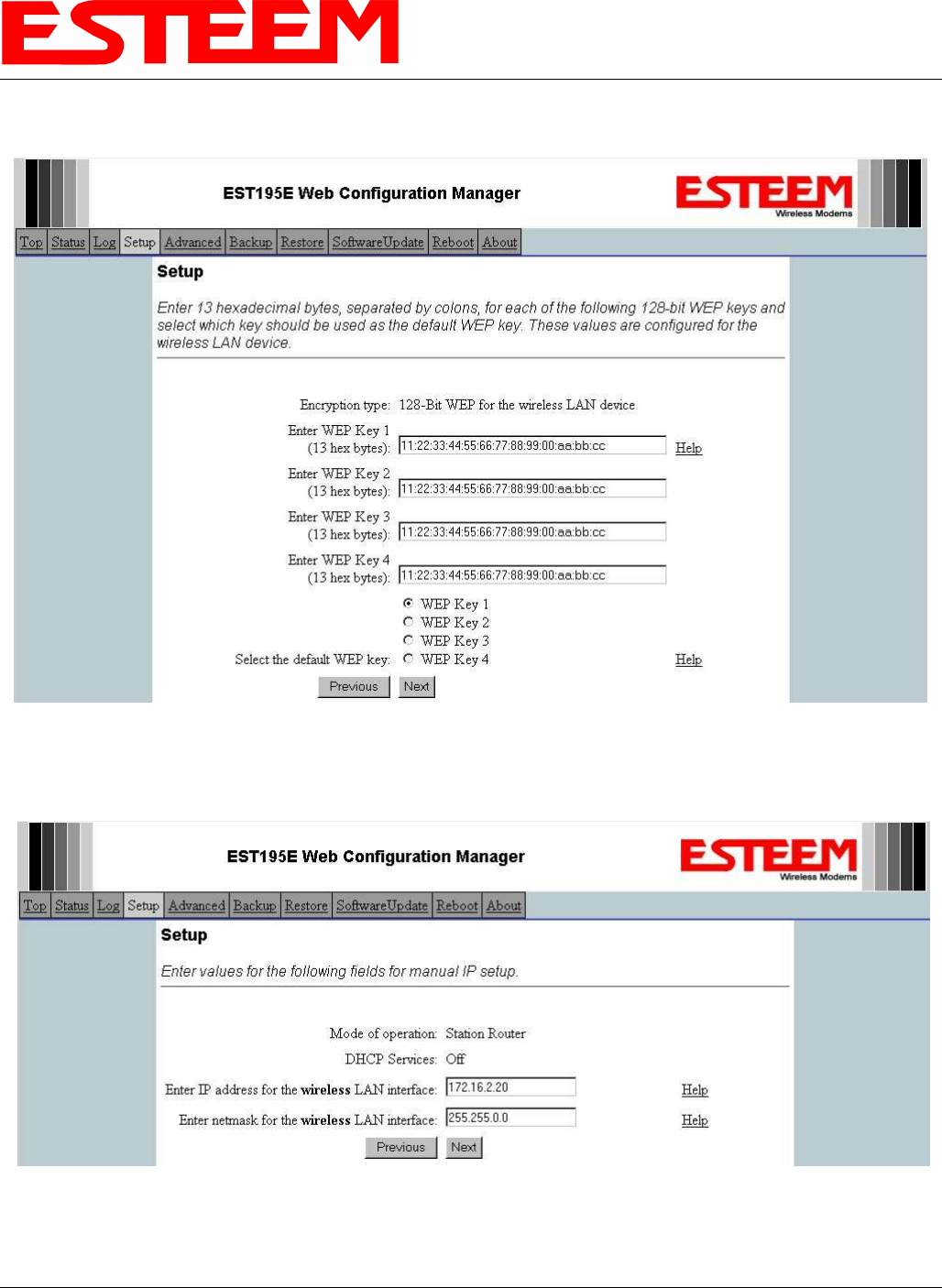
3. Enter the WEP key values for your application that will be used by all devices on the wireless network. Reference Figure 40.
4. Refer to the IP address in Table 1 and enter the wireless IP Address and IP Netmask for the Station Router. Reference Figure
41.
Figure 40:WEP Key Input
Figure 41:Wireless IP Address
CHAPTER 5
EXAMPLE CONFIGURATIONS
Revised: 23 Jan 08 5-24 EST P/N AA107G
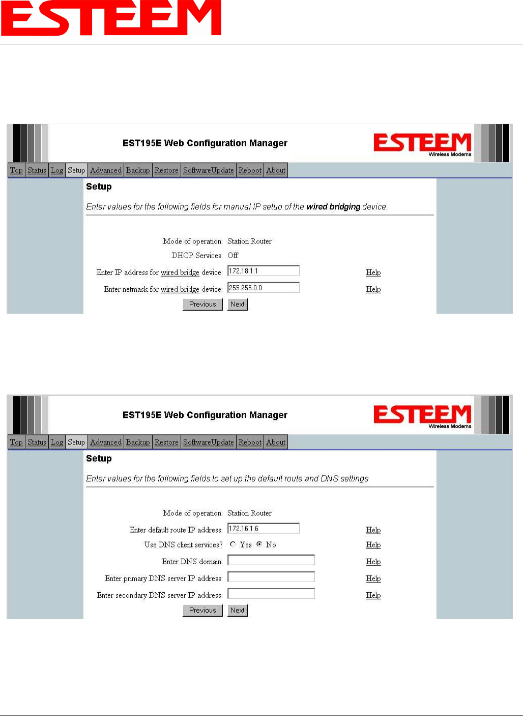
5. Refer to the IP address in Table 1 and enter the ethernet IP address and IP netmask. Reference Figure 42.
Note: When configuring the Ethernet devices connected to the Station Router 195Eg, the ethernet IP address will be their
Gateway address (Figure 37).
6. All IP requests for the Ethernet devices connected to the 195Eg Station Router (Example #5) will need to be resolved by the
Network Router (Figure 37). Enter the default route (Gateway) IP address for the Network Router in the 195Eg. Enter any
DNS server information and press the Next button. Figure 43.
7. Select Commit Changes to write the programming to Flash memory and reboot the Model 195Eg. When the reboot process has
completed (approximately 30 seconds) the modem will be ready to place in operation.
Figure 42:Wired Ethernet IP Address
Figure 43:Default Route (Gateway) Address and DNS Input
CHAPTER 5
EXAMPLE CONFIGURATIONS
Revised: 23 Jan 08 5-25 EST P/N AA107G
Example 6 – Mobile Vehicle #2 (Station Masquerade)
Review the Example Diagram #2 (Figure 2) and locate the 195Eg marked as Example 6. This ESTeem is connected to multiple
Ethernet devices in a mobile application and will be configured Station Masquerade mode. In this mode the 195Eg’s will gain
access to the wireless Ethernet canopy created by the Access Point and act as a firewall between the devices connected to the
Ethernet port and wireless network. Each of these networks will require a unique subnet to operate. In this configuration the
Ethernet devices connected to the Station Masquerade 195Eg can access the wired LAN network, but not the other way around.
This mode could be used if the Remote PC connected to the Station Masquerade needed to access the Internet (connected to the
wired LAN), but did not want to be seen by other Ethernet devices on the network.
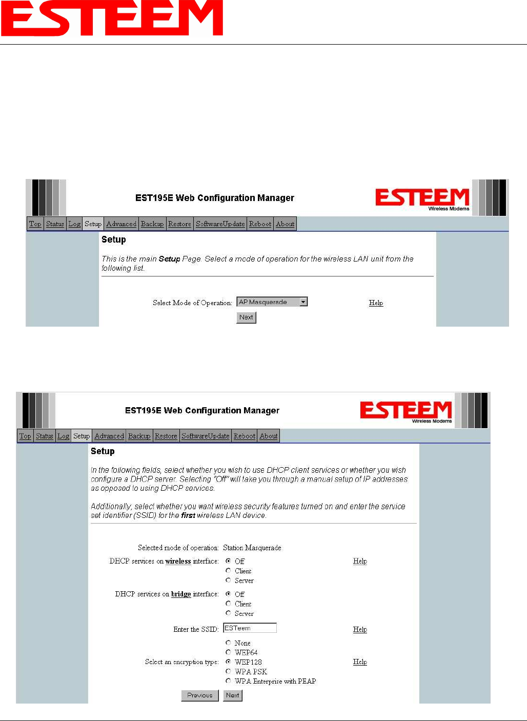
1. Access the ESTeem Web page using your computer’s Web Browser as per instructions in Chapter 4. Select Setup from the
menu items. From the Select Mode of Operation pull down box , select Station Masquerade (Figure 44) and push the Next
button below the pull down box.
Figure 44:Station Masquerade Selection
Figure 45:DHCP, SSID and Encryption Settings
CHAPTER 5
EXAMPLE CONFIGURATIONS
Revised: 23 Jan 08 5-26 EST P/N AA107G
2. Select Yes if you would like to use DHCP services on either the wireless or ethernet connections. Enter the SSID for you
802.11g network. The SSID is the unique identification for your wireless network and all 802.11g devices that share a wireless
network MUST have the same SSID code. This identification code is case sensitive and must NOT contain spaces. Select the
encryption level for the wireless network to match the level of the Access Point canopy. Reference Figure 45.
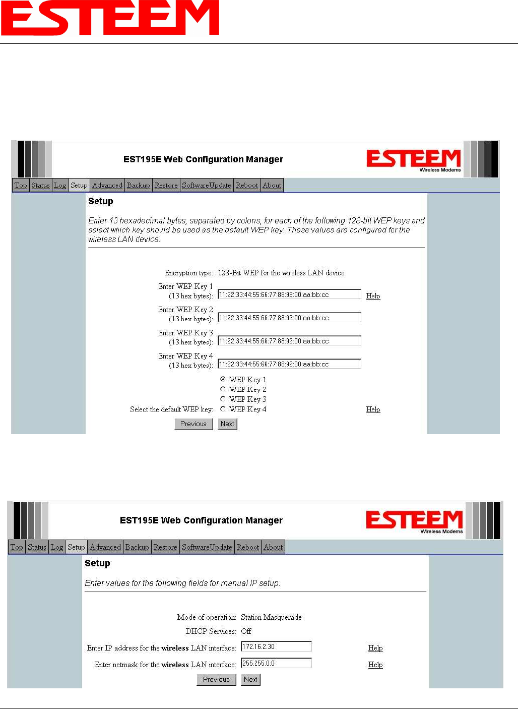
3. Enter the WEP key values for your application that will be used by all devices on the wireless network. Reference Figure 46.
4. Refer to the IP address in Table 1 and enter the wireless IP Address and IP Netmask for the Station Router. Reference Figure
47.
Figure 46:WEP Key Entry
Figure 47:Wireless IP Settings
CHAPTER 5
EXAMPLE CONFIGURATIONS
Revised: 23 Jan 08 5-27 EST P/N AA107G
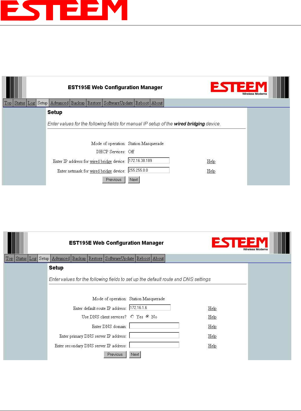
5. Refer to the IP address in Table 1 and enter the ethernet IP address and IP netmask. Reference Figure 48.
Note: When configuring the Ethernet devices connected to the Station Router 195Eg, the ethernet IP address will be their
Gateway address (Figure 37).
6. All IP requests for the Ethernet devices connected to the 195Eg Station Router (Example #5) will need to be resolved by the
Network Router (Figure 37). Enter the default route (Gateway) IP address for the Network Router in the 195Eg. Enter any
DNS server information and press the Next button. Figure 49.
7. Select Commit Changes to write the programming to Flash memory and reboot the Model 195Eg. When the reboot process has
completed (approximately 30 seconds) the modem will be ready to place in operation.
Figure 48:Wired Ethernet Interface
Figure 49:Default Route (Gateway) and DNS Input