Electronic Systems Technology ESTEEM195EG-1 ESTEEM 195Eg User Manual 195Eg Apx B Specifications
Electronic Systems Technology ESTEEM 195Eg 195Eg Apx B Specifications
Contents
user manual apxB
APPENDIX B
SPECIFICATIONS
Model 195Eg Specifications
Revised: 2 Jul 08 APX B-1 EST P/N AA107G
LED Indicators
Power On/Off Receiver On/Off
Carrier Detect On/Off Transmitter On/Off
Link Status On/Off
I/O Connectors
Ethernet 10/100Base T RJ-45
RS-232C Programming/Data Port RJ-45
Dual Antenna input/Outputs TNC Reverse Female
Remote Input Power Power Over Ethernet Cable
Direct Input Power Optional, Header Screw Connector
Transmiter
Frequency of Operation 2.412 to 2.462 GHz
Software Selectable in 11 Channels
RF Data Rates 1,2,5.5,6,9,11,12,18,24,36,48, & 54 Mbps Fixed or Auto Scaling
Tx Peak Output Power 1 Watt
RF Output Impedance 50 ohms
Receiver
Rx Sensitivity -68 dBm @54 Mbps to –89 dBm @ 1 Mbps
Frame Error Rate <10%
Power
Power over Ethernet IEEE 802.3af Standard Power Supply,
48 VDC @ 13 Watts
Power Connector on Unit 10 to 16 VDC
Receive 320 ma @ 12 VDC
Transmit 1000 ma @ 12 VDC
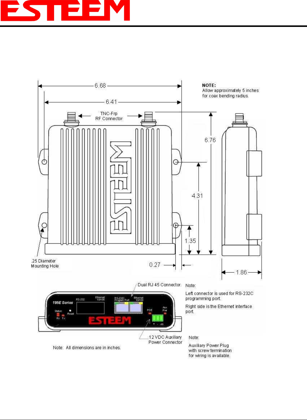
Case
Dimensions 1.9 in. H x 6.7 in. W x 6.2 in. L
Weight 1.25 lbs.
Outdoor Pole Mounting Kit Optional, EST P/N 195PM
Other
Warranty 1 Year
Temperature Range -30° to +60° C
Humidity 95% Non-condensing
FCC Type Acceptance ENPESTEEM195EG-1
Industry Canada Type Acceptance 1457A-195EG
The GPL source code contained in this product is available as a free download from the following:
ftp://ftp.esteem.com/opensource/gplsourcepackage.tar.bz2
If you would like a copy of the GPL source code contained in this product shipped to you on CD,
please send $9.99 to 415 N. Quay Street, Kennewick, WA 99336 which covers the cost of preparing
and mailing a CD to you.
Specifications Subject to Change Without Notice
APPENDIX B
SPECIFICATIONS
Model 195Eg Case Specifications
Revised: 2 Jul 08 APX B-2 EST P/N AA107G
APPENDIX B
SPECIFICATIONS
Antenna Specifications
Revised: 2 Jul 08 APX B-3 EST P/N AA107G
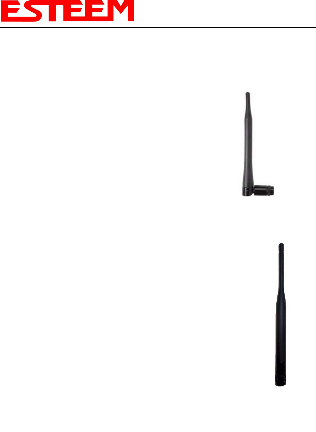
Model No: AA01S
Antenna Type: Omni-Directional, variable angle rubber duck
Applications: Direct mount
Frequency: 2400 to 2485 MHz
Polarization: Vertical
Impedance: 50 ohms
Gain: Unity
VSWR: < 1.5
Front to Back Ratio: n/a
Horizontal Beamwidth: n/a
Vertical Beamwidth: n/a
Antenna Material: Rubber duct whip.
Mounting Hardware: n/a
Antenna Connector: TNC-R Male
Antenna Envelope: 4.25 in. length by 1.75 in width
Weight: .08 lbs.
Model: AA20DMEg
Applications: Model 195Eg direct case mount
Antenna Type: Omni-Directional, Sleeve dipole
Frequency: 2400 to 2485 MHz
Polarization: Vertical
Impedance: 50 ohms
Gain: 5 dBi (3 dBd)
VSWR: < 2:1
Power: 10 W
Front To Back Ratio: n/a
Horizontal Beamwidth: n/a
Vertical Beamwidth: n/a
Antenna Material: Polyurethane Plastic Radome
Recommended Mounting Hardware: n/a
Antenna Connector: TNC-R Male
Flexibility: +/- 20 °
Antenna Envelope: 8.28 in. length by .54 in. width
Temperature: -40 to +70 C°
Weight: 33 grams
Model AA01S
Model AA20DMEg
Caution
Omni-directional antenna
should not be located within
20 cm of personnel.
Caution
Omni-directional antenna
should not be located within
20 cm of personnel.
APPENDIX B
SPECIFICATIONS
Antenna Specifications
Revised: 2 Jul 08 APX B-4 EST P/N AA107G
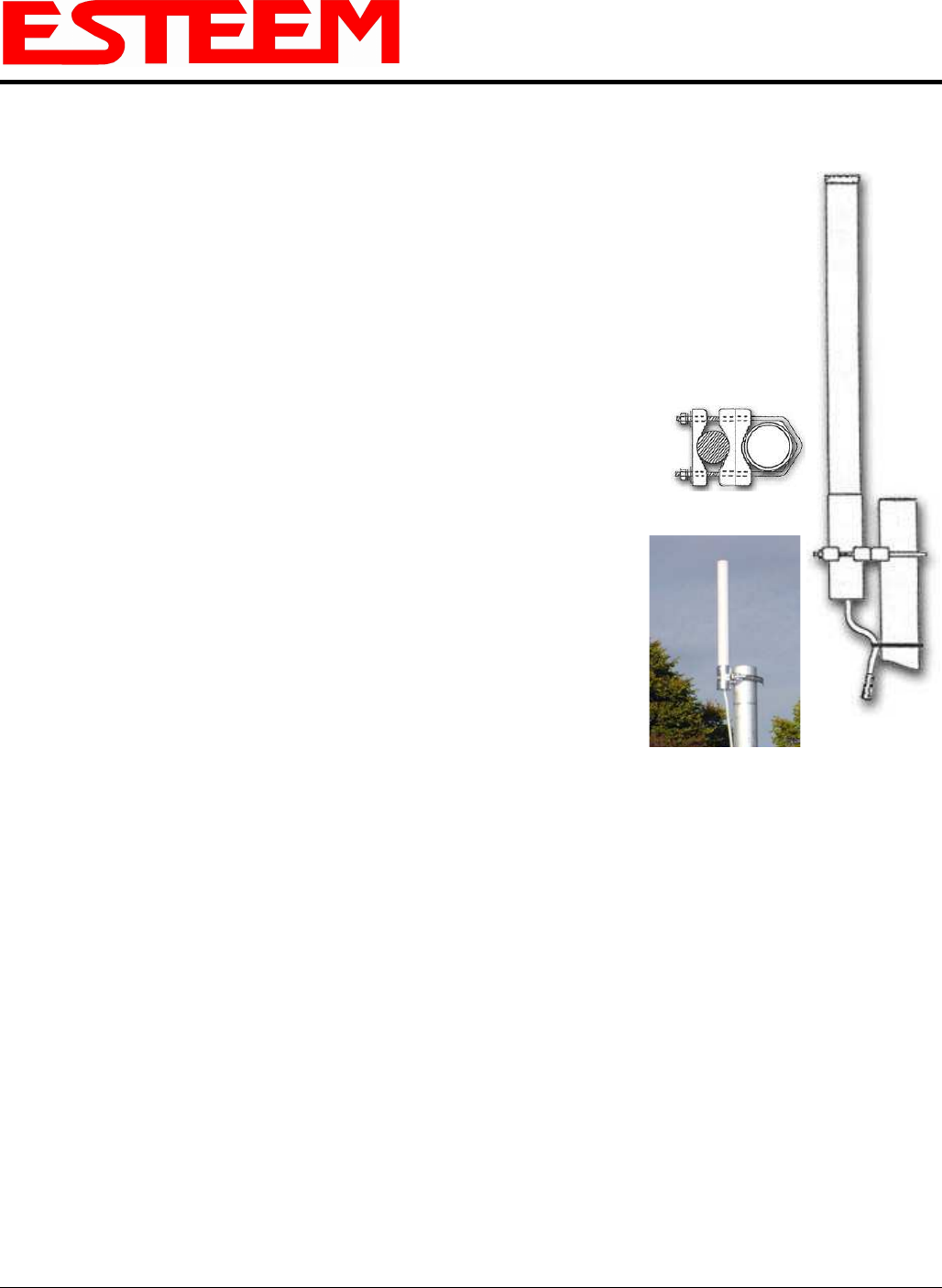
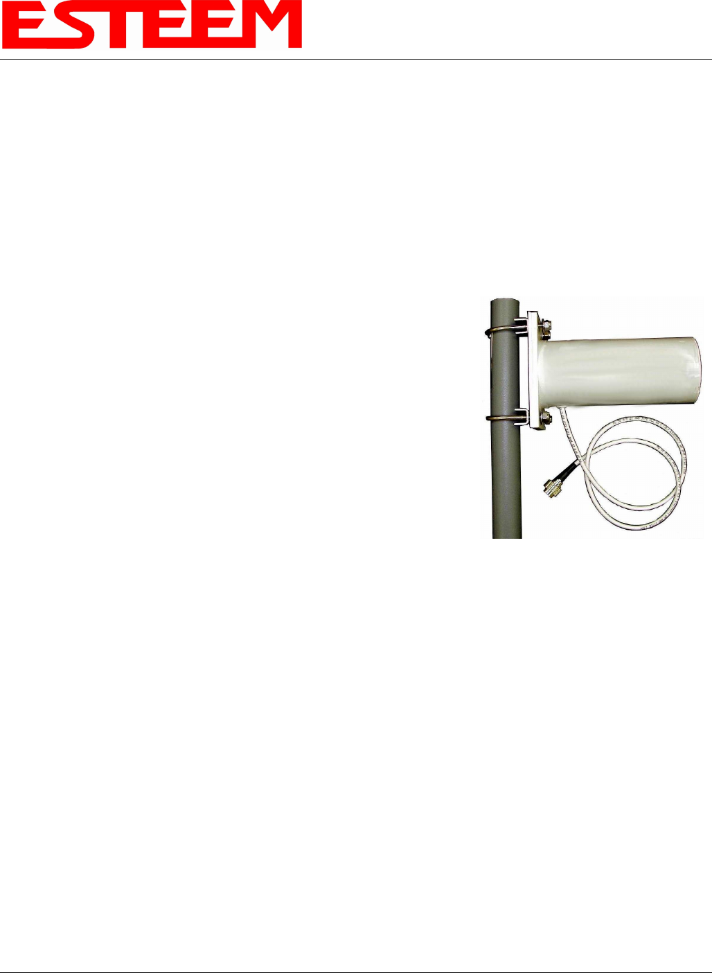
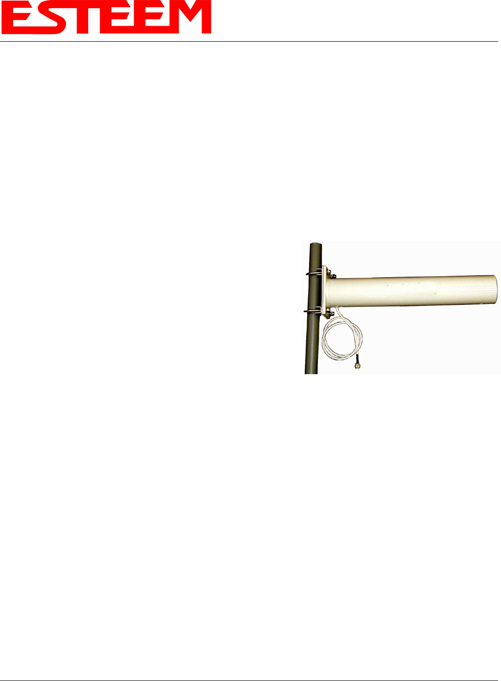
Model No: AA20Eg
Antenna Type: Omni Directional, DC Grounded
Applications: Fixed base
Frequency: 2400 to 2500 MHz
Polarization: Vertical
Impedance: 50 ohms
Gain: 6 dBi (4dBd)
VSWR: 1.2:1 Typical
Front to Back Ratio: n/a
Horizontal Beamwidth: n/a
Vertical Beamwidth: 40 degrees @ ½ power
Antenna Material: Brass radiator, UV inhibited
fiberglass enclosed
Mounting Hardware: Base to Mast, Supplied.
Antenna Connector: TNC-R Male with 36in. pig-tail.
Antenna Envelope: 12 in. length by 1 in. diameter
Weight: 1.5 lbs.
Mounting Bracket
Model AA20Eg
Caution
To comply with the FCC
exposure compliance
requirements, a separation
distance of at least 20 cm
must be maintained between
the antenna and all persons.
APPENDIX B
SPECIFICATIONS
Antenna Specifications
Revised: 2 Jul 08 APX B-5 EST P/N AA107G
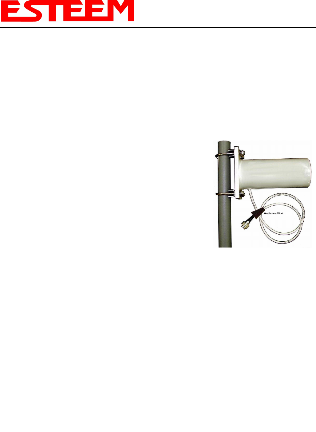
Model No: AA203Eg
Antenna Type: Directional, DC grounded
Applications: Fixed base.
Frequency: 2400 to 2485 MHz
Polarization: Vertical or Horizontal
Impedance: 50 ohms
Gain: 6 dBi (4 dBd)
VSWR: < 1.5
Front to Back Ratio: >23 dB
Horizontal Beamwidth: 55 degrees @ ½ power
Vertical Beamwidth: 55 degrees @ ½ power
Antenna Material: Sealed in UV stable fiberglass enclosed radome
Mounting Hardware: Stainless steel U bolts (included) for mounting up
to 1 5/8 in. diameter pipe.
Antenna Connector: TNC-R Male with 36in. pig tail
Maximum Power Input: 5 Watts
Antenna Envelope: 4.5 in. length by 3 in. diameter
Windload (RWV): 125 mph
Lateral Thrust at
Rated Wind: 5.8 lbs.
Wind Surface Area: 0.060 ft
2
Weight: 1 lbs.
Model AA203Eg
Caution
To comply with the FCC
exposure compliance
requirements, a separation
distance of at least 20 cm
must be maintained between
the antenna and all persons.
APPENDIX B
SPECIFICATIONS
Antenna Specifications
Revised: 2 Jul 08 APX B-6 EST P/N AA107G
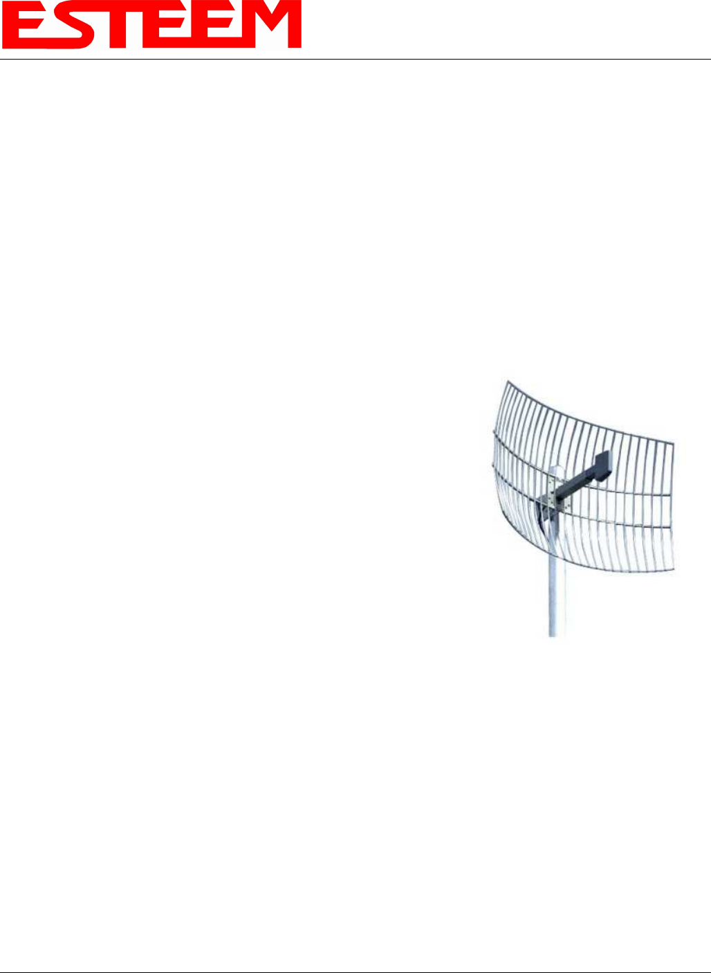
Model No: AA204Eg
Applications: Fixed base mounting
Antenna Type: 2.4 GHz ISM, Directional, DC Grounded, Parabolic Grid
Frequency: 2400-2485 MHz
Polarization: Vertical or Horizontal
Impedance: 50 ohms
Gain: 19 dBi (17 dBd) nominal
VSWR: < 1.5:1 nominal
Front to Back Ratio: >24 dB
Horizontal Beamwidth: 16 degrees @ ½ power
Vertical Beamwidth: 11 degrees @ ½ power
Antenna Material: Zinc plated cold rolled steel with polyester power
coat finish
Recommended Mounting
Hardware: Standard U-bolt steel mast clamp complete with
mounting hardware. Designed for masts of up to
2.5 in. O.D.
Antenna Connector: TNC-R Male with 36 in. pig-tail
Maximum Power Input: 10 Watts
Wind Survival: 100 mph
Wind Load: 16 mph
Antenna Envelope: 34 in. length by 17 in. width by 11 in. height
Weight: 3 lbs.
Use of the AA204Eg, directional antenna is limited to fixed point-to-point applications only. In accordance with FCC
Section 15.247(b)iii, this antenna must be professionally installed. The installer must ensure the system is used exclusively
for fixed, point-to-point applications and the ESTeem Model 195Eg is set for 0.25 Watts output power (Power Level =
Min).
Model AA204Eg
Caution
To comply with the FCC exposure
compliance requirements, a
separation distance of at least 50 cm
must be maintained between the
antenna and all persons.
APPENDIX B
SPECIFICATIONS
Antenna Specifications
Revised: 2 Jul 08 APX B-7 EST P/N AA107G
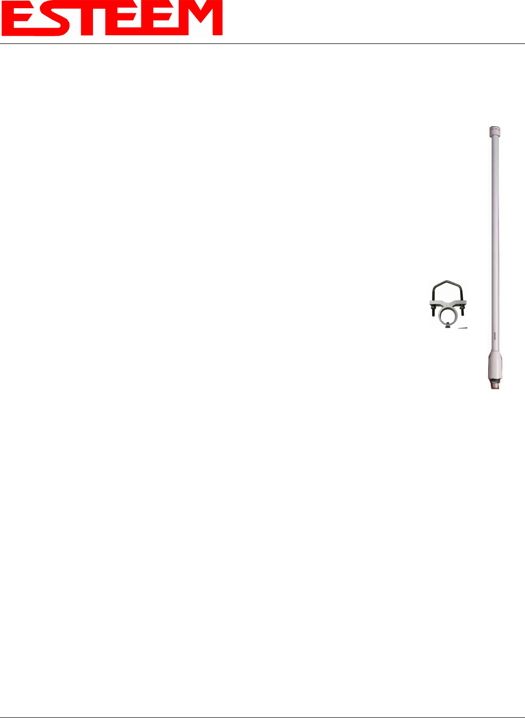
Model No: AA20E
Antenna Type: Omni Directional, DC Grounded
Applications: Fixed base
Frequency: 2400 to 2500 MHz
Polarization: Vertical
Impedance: 50 ohms
Gain: 6 dBd
VSWR: < 1.5
Front To Back Ratio: n/a
Horizontal Beamwidth: n/a
Vertical Beamwidth: 35 degrees @ ½ power
Antenna Material: Copper alloy radiator, UV inhibited fiberglass enclosed
Mounting Hardware: Aluminum bracket for mounting to 1 ¼ to 2 in. diameter mast
included.
Antenna Connector: N female reverse polarity.
Antenna Envelope: 20 in. length by 1.35 in. diameter
Weight: 2 lbs.
Only pre-made coax cables from the factory used in conjunction with either the AA20E omni-directional and AA203ES or
AA204ES directional antennas meet all FCC Section 15.247(b) EIRP maximum power requirements. See Chapter 8 for
details on maximum cable lengths.
Model AA20E
Mounting
Bracket
Caution
To comply with the FCC
exposure compliance
requirements, a separation
distance of at least 20 cm
must be maintained between
the antenna and all persons
APPENDIX B
SPECIFICATIONS
Antenna Specifications
Revised: 2 Jul 08 APX B-8 EST P/N AA107G
Model No: AA203ES
Antenna Type: Directional, 6 element yagi, DC grounded
Applications: Fixed base.
Frequency: 2400 to 2483.5 MHz
Polarization: Vertical or Horizonal
Impedance: 50 ohms
Gain: 7 dBd
VSWR: < 1.5
Front To Back Ratio: 13.5 dB
Horizontal Beamwidth: 47 degrees @ ½ power
Vertical Beamwidth: 55 degrees @ ½ power
Antenna Material: Sealed in UV stable fiberglass enclosed radome
Mounting Hardware: Stainless steel U bolts (included) for mounting up
to 1 5/8 in. diameter pipe.
Antenna Connector: N male reverse polarity with 18 in. pig tail
Maximum Power Input: 50 Watts
Antenna Envelope: 7 1/4 in. length by 2.0 in. diameter
Windload (RWV): 120 mph
Lateral Thrust at
Rated Wind: 12.2 lbs.
Wind Surface Area: 0.146 ft
2
Bending Moment at
Base Rated Wind: 3.6 lb-ft.
Weight: .48 lbs.
Only pre-made coax cables from the factory used in conjunction with either the AA20E omni-directional and AA203ES or
AA204ES directional antennas meet all FCC Section 15.247(b) EIRP maximum power requirements. See Chapter 8 for
details on maximum cable lengths.
Model AA203ES
Caution
To comply with the FCC
exposure compliance
requirements, a separation
distance of at least 100cm
must be maintained between
the antenna and all persons.
APPENDIX B
SPECIFICATIONS
Antenna Specifications
Revised: 2 Jul 08 APX B-9 EST P/N AA107G
Model No: AA204ES
Applications: Fixed base mounting
Antenna Type: 2.4 GHz ISM, Directional, 16 Element Yagi, DC Grounded
Frequency: 2400-2483.5 MHz
Polarization: Vertical or Horizontal
Impedance: 50 ohms
Gain: 13.5 dBi (11.3 dBd nominal)
VSWR: < 2.1, 1.5:1 nominal
Front To Back Ratio: >20 dB
Horizontal Beamwidth: 28 degrees @ ½ power
Vertical Beamwidth: 30 degrees @ ½ power
Antenna Material: Fiberglass enclosed
Recommended Mounting
Hardware: Heavy duty U bolts for mounting up to 1
5/8 in. pipe (included). Adjustable yagi
mounting kit for mounting up to 1 ½ in.
pipe optional
Antenna Connector: N male reverse polarity
Cable Length: 18 in.
Maximum Power Input: 50 Watts
Wind Survival: 120 mph
Antenna Envelope: 18 in. length by 3 in. width
Equiv. Flat Plate Area: 0.375 ft²
Lateral Thrust at Rated
Wind: 31.4 lbs.
Bendling Moment at
Base Rated Wind: 23.6 lb-ft.
Weight: .76 lbs.
Only pre-made coax cables from the factory used in conjunction with either the AA20E omni-directional and AA203ES or
AA204ES directional antennas meet all FCC Section 15.247(b) EIRP maximum power requirements. See Chapter 8 for
details on maximum cable lengths.
Use of the AA204ES, directional antenna is limited to fixed point to point applications only. In accordance FCC Section
15.247(b)iii, the operator or installer is responsible for ensuring the systems is used exclusively for fixed, point-to-point
applications.
Model 204ES
Caution
To comply with the FCC exposure
compliance requirements, a
separation distance of at least 100cm
must be maintained between the
antenna and all persons.