Electronic Systems Technology ESTEEM195EG-1 ESTEEM 195Eg User Manual Chapter 0 Front Cover 195Eg
Electronic Systems Technology ESTEEM 195Eg Chapter 0 Front Cover 195Eg
Contents
user manual ch 3 to 4
CHAPTER 3
STARTING OUT
Revised: 21 Mar 08 3-1 EST P/N AA107G
OVERVIEW
Most configuration of the ESTeem Model 195Eg is completed using the internal Web interface (discussed in detail in Chapter 4),
but to access the modem through a web browser requires first setting the TCP/IP address. The TCP/IP address (IP address) is set at
the factory for a static Class B (172.16.xxx.xxx - Mask 255.255.0.0) and listed on the ESTeem documentation. If this IP address
does not match your network configuration, you will need to use either the ESTeem 195E Discovery program or the RS-232
interface to set the IP address in the 195Eg.
QUICK START GUIDE
A printed copy of the Model 195Eg Quick Start Guide was provided in the documentation package that arrived with your new
ESTeem 195Eg. This guide is an abbreviated step-by-step procedure on configuration of the 195Eg for most Ethernet bridging and
Access Point applications. A copy of the Quick Start Guide is provided in Appendix G of this User’s Manual for convenience.
MODEL 195Eg HARDWARE LAYOUT
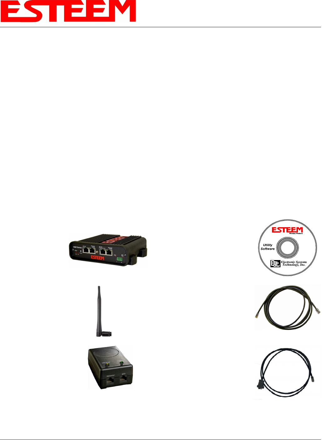
Unpack the ESTeem Model 195Eg shipping boxes and locate the items contained below for initial configuration. Take a few
minutes to inventory your equipment before you proceed. Report any missing or damaged items to Customer Support (509-735-
9092) as soon as possible.
Each node in your ESTeem Model 195Eg’s network may have different hardware components based upon the final installation
location (i.e Outdoor, Indoor, Point-to-point or Muti-Point). Antenna types, cable lengths, power supplies may be different, but the
following items will be required for basic setup:
Model 195Eg
AA109 Resource Disk
Antenna
(AA01S Displayed)
(2) Ethernet Cables
Power Supply
(AA175 Displayed)
Serial Interface Cable
(AA6021.1)
Note: Your accessory model numbers may vary from the above, but you will need to locate each of above items to continue
configuration.
CHAPTER 3
STARTING OUT
Revised: 21 Mar 08 3-2 EST P/N AA107G
Notes:
• There is no Power On/Off switch on the Model 195Eg.
• Attach the programming Cable to the RS-232 Programming Port and the Patch Cable between the Power Supply and
Ethernet port.
• One word of caution, always attach an antenna to Port A (Figure 2) on the Model 195Eg before power up.
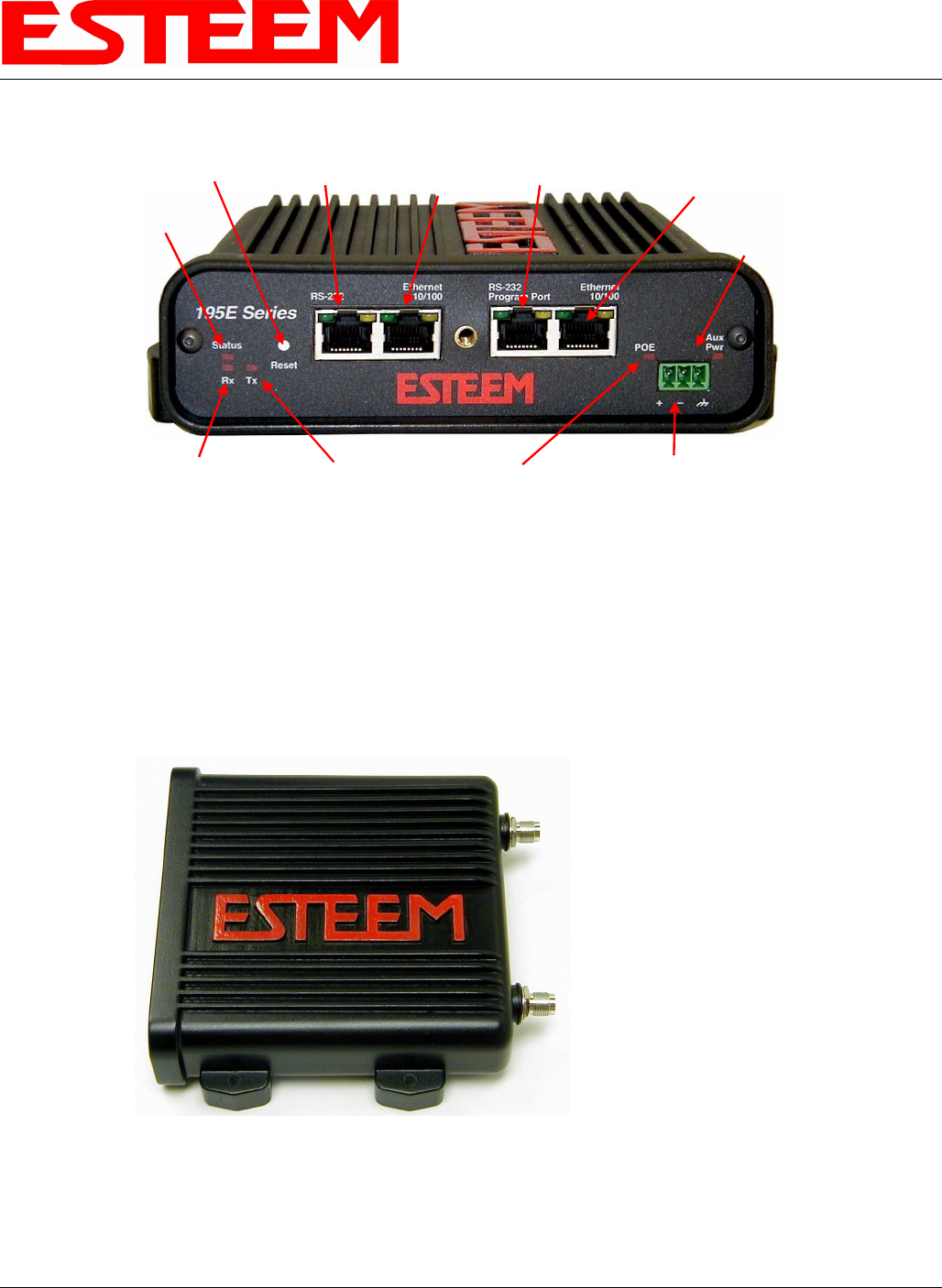
MODEL 195Eg HARDWARE CONFIGURATION
12 VDC Input
(Auxiliary
Connector )
Reset Switch RS-232
Configuration RJ-45 10/100BaseT
Ethernet Port
Transmit
LED
Receive
LED
Status
LED
Power over
Ethernet LED
Aux Power
LED
RS-232
Data Port
Second
Ethernet
Port
Figure 1: 195Eg Front Panel Overview
Antenna Connectors
(TNC Female-RP)
Antenna Port A
(Single Receive Antenna)
Antenna Port B
(Dual Receive Antennas)
Figure 2: 195Eg Antenna Overview
(Optional)
CHAPTER 3
STARTING OUT
Revised: 21 Mar 08 3-3 EST P/N AA107G
The following steps should be completed before any modifications are made to the IP address in the ESTeem Model 195Eg:
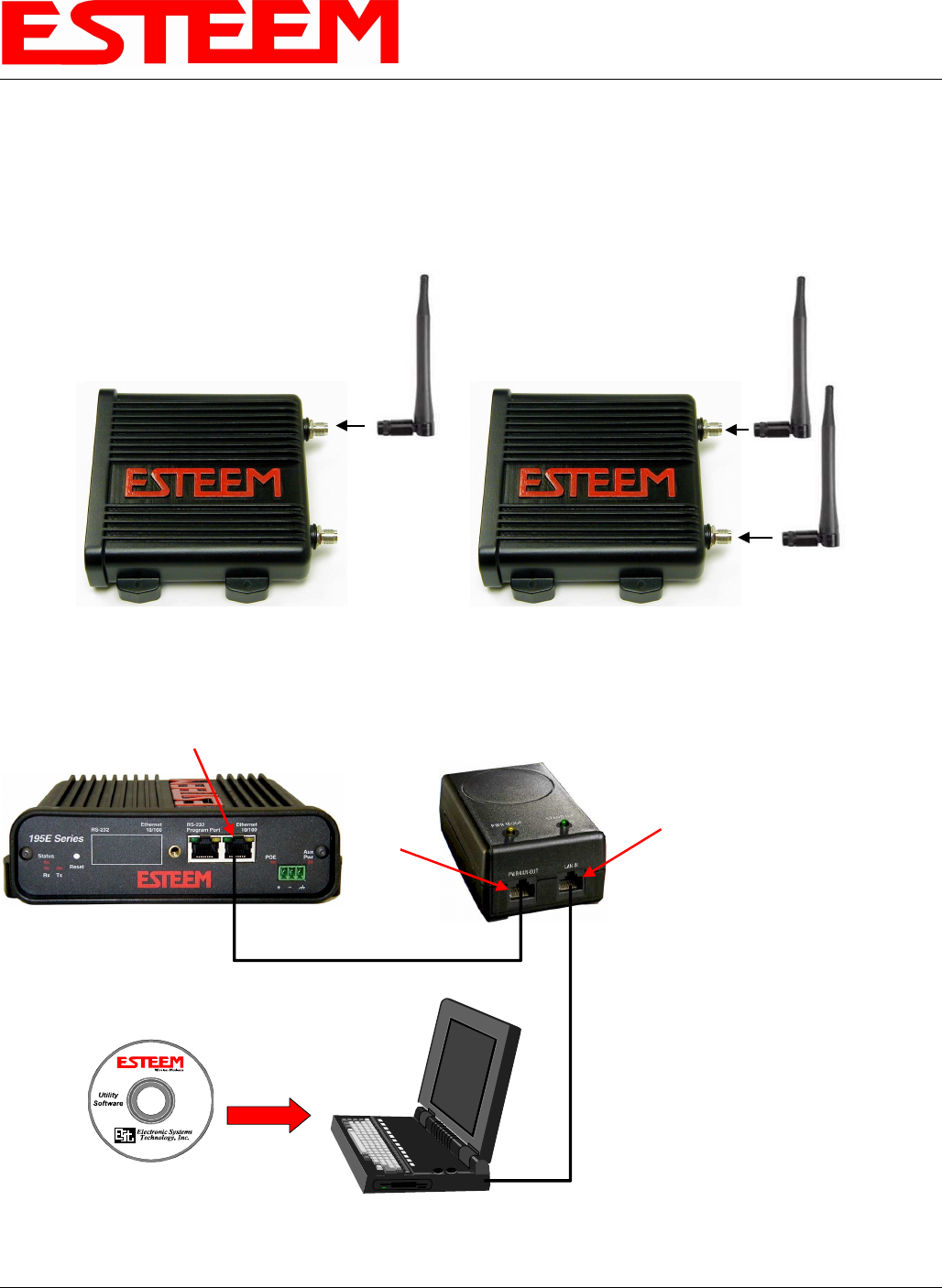
1. Connect the antenna to the antenna connector on the ESTeem Model 195Eg (Figure 3). For a single antenna use Antenna Port
A and connect both if using dual antennas.
2. Assemble the 195Eg hardware as shown in Figure 4.
Leave
Open
Single Antenna
Configuration Dual Antenna
Configuration
Figure 3: Antenna Configuration Diagram
PC with Web
Browser Software
RJ-45 10/100BaseT
Ethernet Port
10/100BaseT
Ethernet Cable
(Patch or Cross Over)
AA175 PoE
Power Supply
LAN In
10/100BaseT
Ethernet Cable
(Patch or Cross Over)
PWR
Data Out
AA109
Resource
Disk
Figure 4: Hardware Configuration Diagram
Notes:
• Configure the Model
195Eg prior to
mounting.
• Some of the following
steps, such as
connecting the serial
cable, are easier to
perform if the ESTeem
is accessible.
• Please attach an
antenna to the Model
195Eg before power up.
• There is no Power
On/Off switch on the
Model 195Eg.

CHAPTER 3
STARTING OUT
Revised: 21 Mar 08 3-4 EST P/N AA107G
3. Complete the following System Configuration Table. The Model 195Eg will link to other Model 195Eg’s on the network
via the WLAN Media Access Control (MAC) address found on the bottom of the case. This MAC address is six
hexadecimal digits separated by colons and is configured at the factory. Every MAC address in the world is unique and
can not be changed. Complete the following chart to aid in your when defining modes of operation and repeater routes.
Modem_ID(Name)
/Operating Mode Serial Number IP Address Ethernet MAC WLAN MAC
Example Modem 1
AP_Bridge E-14001
172.16.8.101 00:04:3f:00:01:01 00:04:3f:00:01:02

CHAPTER 3
STARTING OUT
Revised: 21 Mar 08 3-5 EST P/N AA107G
ESTEEM DISCOVERY UTILITY
The ESTeem Discovery Utility will allow you to
configure the IP address on the Model 195Eg to match
your network. Install the Discovery Utility on your
computer by inserting the Resource Disk in your CD
drive.
Note: The ESTeem Resource Disk is stand-alone copy of
the ESTeem Web site (Figure 5). Navigation of the
Resource Disk is as simple as using your web browser.
All technical documentation, User’s Manuals and the
ESTeem Utility Program is available on the disk.
1. Place the ESTeem Utility CD in your CD-ROM
drive. The CD will auto load the ESTeem main
page
Note: If the page does not auto load, open your web browser and set your address line to D:\index.html (Where D: is the
drive letter for your CD-ROM drive).
2. From the Main Page select ESTeem Utilities and click on ESTeem Discovery Utility (Figure 6).
Note: This program is saved in a compressed file format. Microsoft Windows XP® will open the file directly, but other
operating systems will require a common compression program such as WinZip available for download at
http://www.winzip.com
3. Double click on the 195EdiscoverySetup.exe file listed in the window to install the program.
Figure 5: ESTeem Resource Main Page
Figure 6: Discovery Utility Download
CHAPTER 3
STARTING OUT
Revised: 21 Mar 08 3-6 EST P/N AA107G
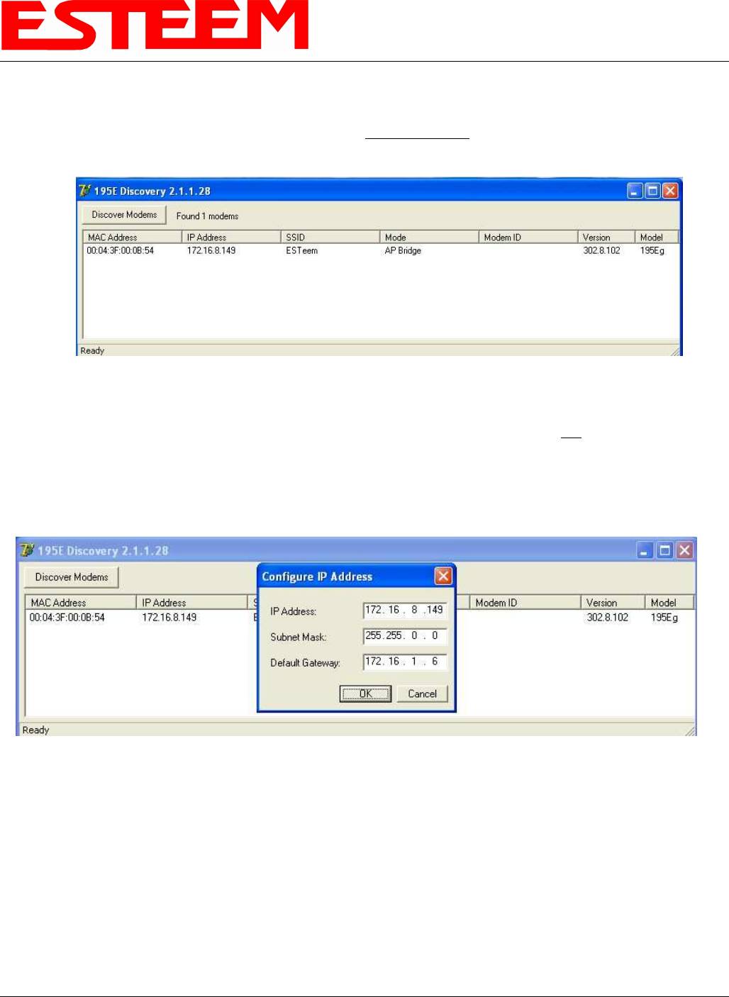
4. Connect the Model 195Eg to your computer either direct to the Ethernet card or through a HUB/Switch using a CAT-5e
Ethernet cable. The Ethernet port on the 195Eg supports Auto-Negotiation so either a patch cable or crossover cable will
work. Open the ESTeem Discovery Program and press the Discover Modems button. The Model 195Eg will be displayed
in the program by the Ethernet MAC address and Current IP Address (Figure 7).
Note: The SSID and Mode of Operation will be adjusted later in the configuration.
5. Double-click on the 195Eg you want to program and the Configure IP Address window will be displayed (Figure 8). Enter
an IP address and Subnet Mask for the 195Eg that matches your network subnet and press the OK button to save this to the
ESTeem. You will receive notification that the Configuration was Successful and the 195Eg will reboot. Proceed to
ESTeem Setup in Chapter 4.
Figure 7: Discovery Program Main Page
Figure 8: Change IP Address Window
CHAPTER 3
STARTING OUT
Revised: 21 Mar 08 3-7 EST P/N AA107G
USING THE RS-232 INTERFACE
Any terminal emulation program that can run with VT100 emulation can be used for this configuration of the ESTeem. Most
Windows users will probably use either Hyper Terminal or the Terminal Emulation in the ESTeem Utility program. Configure
your RS-232C port for a Baud Rate to 38,400, Data Bits to 8, Parity to None, Stop Bits to 1 and Handshaking to None and set
the Emulation type to VT100. Once your ESTeem has an IP address, you can attach the ESTeem to your network and use the
Web Server for further programming.
Installing Esteem Utility Program
The ESTeem Utility program version 2.7.0 and above can configure
the Terminal Emulation to VT100 for easy navigation of the
configuration menu. The ESTeem Utility Program is located on the
ESTeem Resource Disk (AA109) which is stand-alone copy of the
ESTeem Web site (Figure 5). Navigation of the Resource Disk is as
simple as using your web browser. All technical documentation,
User’s Manuals and the ESTeem Utility Program is available on the
disk. To install the ESTeem Utility Program use the following
instructions:
1. Place the ESTeem Utility CD in your CD-ROM drive. The CD
will auto load the ESTeem main page (Figure 9).
2. If the page does not auto load, open your web browser and set
your address line to D:\index.html (Where D: is the drive letter
for your CD-ROM drive).
3. From navigation menu on the left side of the page, select ESTeem
Utilities (Figure 1).
4. Select the Windows version of the ESTeem Utility and click Download Windows Utility for Model 192 Series. When asked
to Open or Save the file, press Open to view the contents of the Zip file.
5. Double Click on the Setup.exe file to start the Utility Installation or extract the files to a directory for later installation.
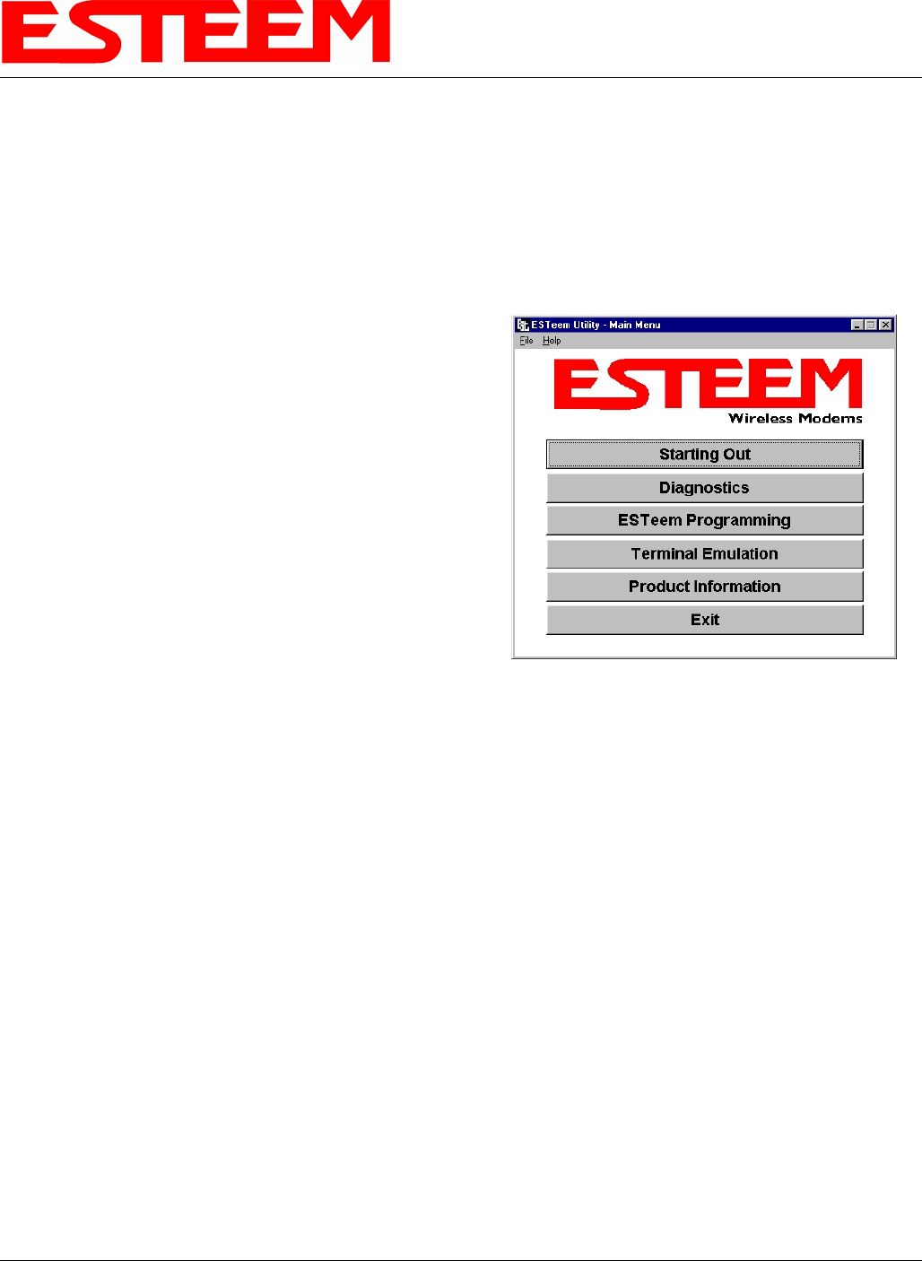
6. Once the installation is complete, Press the Start button on your Window desktop and select Programs. Select ESTeem Utility
from the list of program folders then click ESTeem Utility from the list of files and the program will start (Figure 2).
When prompted, configure your RS-232C port for a Baud Rate to 38,400, Data Bits to 8, Parity to None, Stop Bits to 1 and leave
the Flow Control boxes unchecked. You will now be ready to continue with the configuration of the Model 195Eg.
Programming Using the RS-232 Port
1. When configuring the Model 195Eg for the first time you must use the ESTeem RS-232C Configuration Menu to setup the
basic operating parameters such as assigning the IP Address, IP Net Mask, Gateway IP Address, Domain Name, and DNS IP
Address.
2. Connect the serial cable (EST P/N: AA0621.1) between the RS-232 connector (RJ-45) on the Model 195Eg to the serial port on
the computer.
3. Any terminal emulation program can be used for the configuration of the Model 195Eg. Most users will use the Terminal
Emulation section of the ESTeem Utility Program. Configure your RS-232C port for a Baud Rate to 38,400, Data Bits to 8,
Parity to None, Stop Bits to 1, use No Handshaking (Flow Control) and set the Terminal to VT100 emulation.
4. Plug the Model AA175 power supply into a wall socket and connect an Ethernet patch cable from the Model 195Eg Ethernet
port to the J1 (Data&PWR) port on the power supply (Figure 5). The Power over Ethernet (POE) LED on the front of the
ESTeem should be illuminated.
Figure 9: ESTeem Utility Main Menu
CHAPTER 3
STARTING OUT
Revised: 21 Mar 08 3-8 EST P/N AA107G
5. If your computer is configured properly, you will see the ESTeem Model 195Eg booting sequence on your Terminal Emulation
program. Once the ESTeem boot sequence is complete (approximately 30 seconds) you will receive this message:
“Please press Enter to active this console.”
If you don’t see this message press the Reset button on the front panel of the Model 195Eg and/or check the programming of
your RS-232 port.
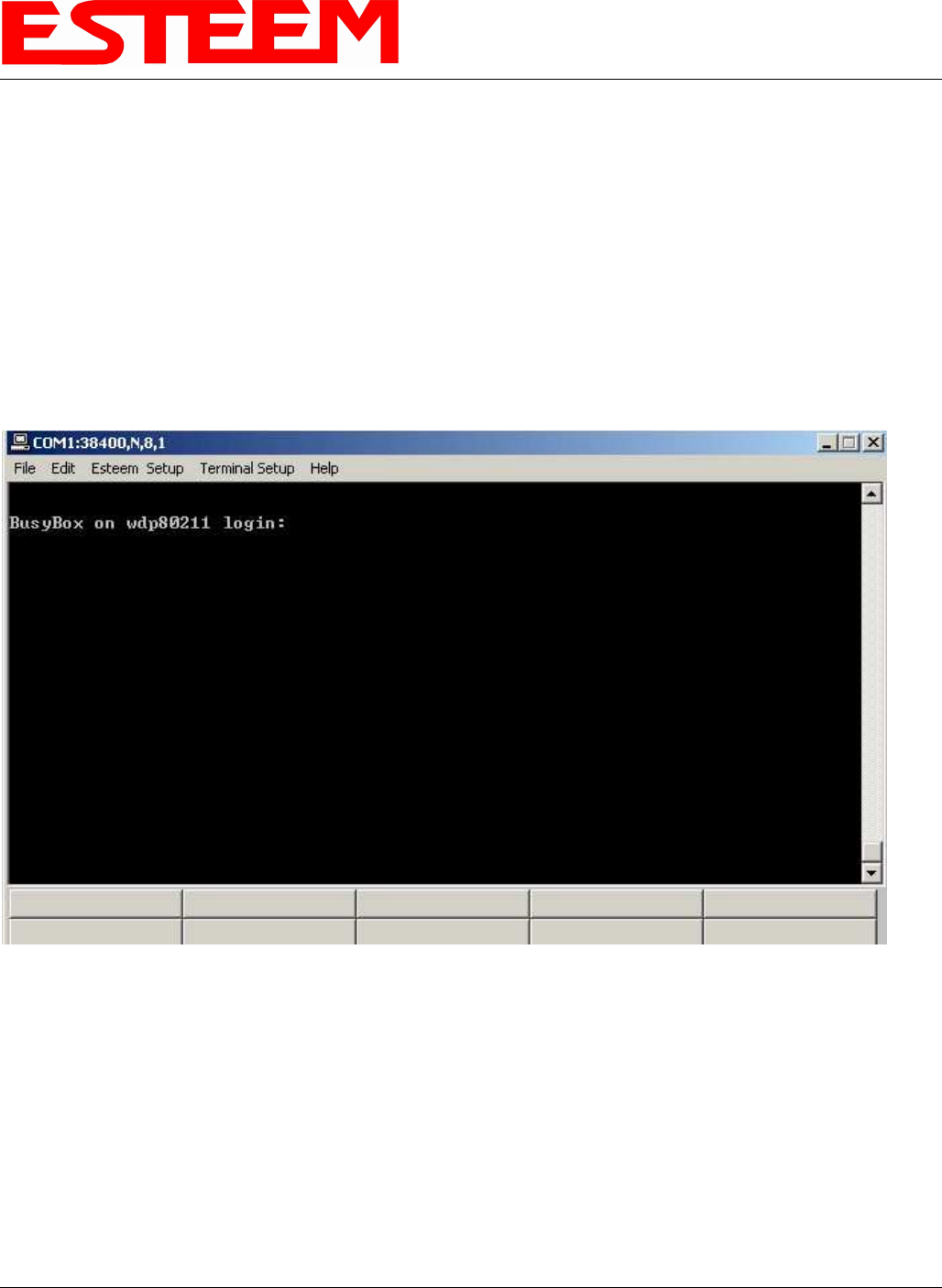
6. Press the Enter key and you will be at the Configuration Menu 195Eg login prompt. See Figure 10.
7. To enter the Model 195Eg Main Menu you will need to log into the system with a login name and password.
8. If this is not the first time configuration of the Model 195Eg, see your network systems administrator for the password.
9. At the 195Eg login prompt type admin for the login name and press the Enter key (<Enter>). The login name is defined at the
factory and is not changeable by the user. Note that all characters are lower case.
10. If this is the first time the Model 195Eg has been programmed or the Password was not changed from the factory default
values, the factory default password is also admin. Enter admin for the password and press the Enter key (<Enter>).
Note: All characters are lower case.
Figure 10: RS-232 Port Log-in Screen
CHAPTER 3
STARTING OUT
Revised: 21 Mar 08 3-9 EST P/N AA107G
11. The ESTeem Configuration Welcome Screen (Figure 11) will now be displayed. Press the Enter key to continue on the Top
menu items.
Note: The configuration menu functions the same as the Web Configuration Manager, but requires moving the arrows to
change fields. To move left and right on the Menu Items use the Up and Down arrow keys and press Enter to
select the highlighted item.
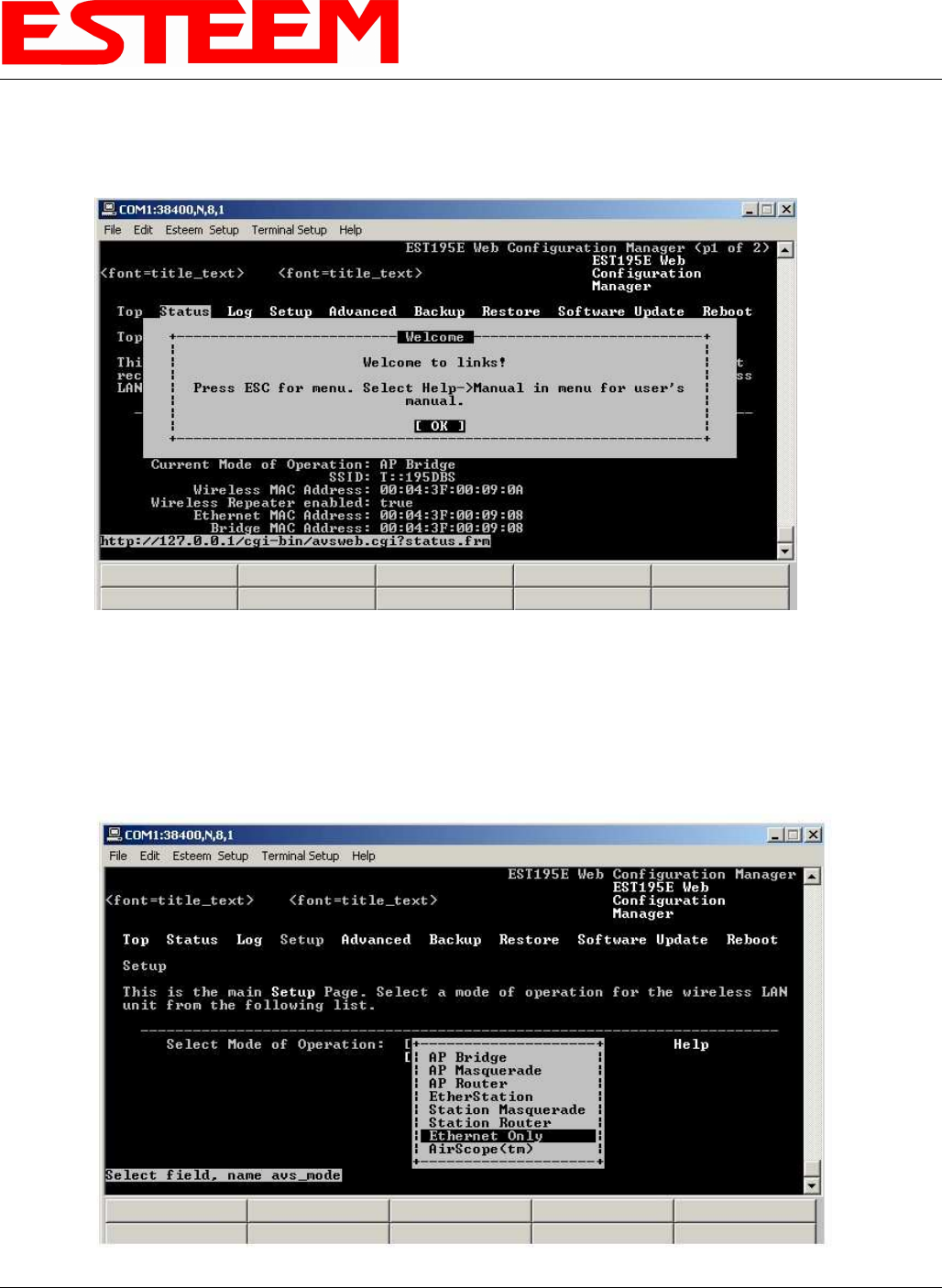
12. Press the Down Arrow key until the SETUP menu item is highlighted and press Enter. Again press the Down Arrow key until
the Mode of Operation is highlighted and press Enter again to bring up the mode selection menu (Figure 12).
Figure 11: RS-232 Welcome Screen
Figure 12: Setup Ethernet Only Screen
CHAPTER 3
STARTING OUT
Revised: 21 Mar 08 3-10 EST P/N AA107G
13. Select Ethernet Only and press the Enter key. In the initial configuration it is best not to use the ESTeem as a DHCP client.
Select OFF on the DHCP client services on the next screen and continue the process selecting Next and Posting the information.
Program the basic operating parameters such as assigning the Model 195Eg an IP Address, IP Net Mask, Gateway IP Address,
Domain Name, or DNS IP Address.
Note: Next to all items in the configuration menu are Help screens that define all the settings and provide assistance on
configuring the Model 195Eg.
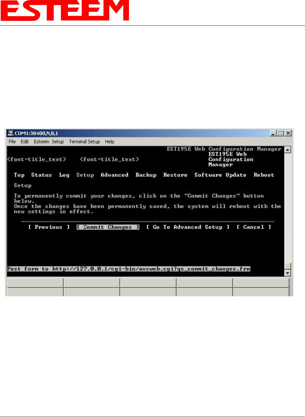
14. After the basic parameters have been entered into the Model 195Eg you will need to commit the changes to the Model 195Eg
(Figure 13). The changes will be saved to flash memory. You can use programming features in the ESTeem Web
Configuration Manager to configure the unit for your application. Proceed to Chapter 4.
Figure 13: Commit Changes Screen
CHAPTER 4
WEB CONFIGURATION
Revised: 21 Mar 08 4-1 EST P/N AA107G
The ESTeem Model 195Eg Web Configuration Manager is an internal web server that will allow setup, monitoring and diagnostics
of all operating parameters in the Model 195Eg. The 195Eg can be configured using any current web browser software such as
Internet Explorer, Netscape or Mozilla.
LOGGING ON TO THE ESTeem WEB PAGE
1. Using your Web Browser connect to the Model 195Eg Web
Page with the IP Address that you have assigned it in Chapter 3.
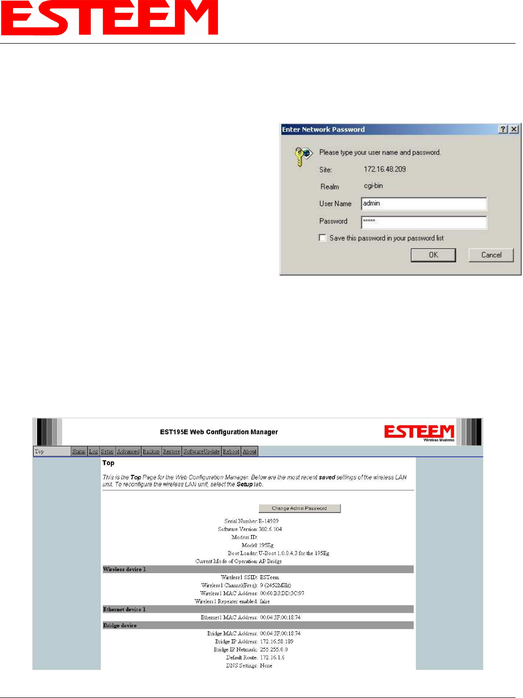
2. You will now see the Log-on Menu on Figure 1. To enter the
Model 195Eg Top Menu you will need to log into the system
with a User Name and Password.
3. For the User Name enter admin and press the Enter key
(<Enter>). The User Name is defined at the factory and is not
changeable.
4. Enter your Password and press the Enter key (<Enter>).
If this is the first time the Model 195Eg has been programmed
and Password was not changed from the factory default values, proceed with the steps below to access the Configuration
Menu.
• The factory default Password is also admin. Enter admin for the Password and press the Enter key (<Enter>).
• Note: All characters are lower case.
5. After Log-in the next screen displayed will be the Model 195Eg Top Menu page (Figure 2). This example screen shows the
Top Menu screen.
Note: Throughout the Configuration Manager are Help Screens that can accessed for further information on each item.
Figure 1: ESTeem Web Page Log-on Screen
Figure 2: Top Menu Screen

CHAPTER 4
WEB CONFIGURATION
Revised: 21 Mar 08 4-2 EST P/N AA107G
WEB CONFIGURATION MANAGER SECTIONS
The following sections will describe the features in each of the main and sub menu items in the web pages. For step-by-step
examples of how to configure the Model 195Eg in different Modes of Operation, please refer to Chapter 5 – Example
Configurations.
Top Menu
The Top Menu will be the default web page for the Model 195Eg Web Configuration Manager (Figure 2). This section will
display the current configuration summary for the Model 195Eg and allow changing of the default password. This page will also
display the Modem ID field that can be used to easily identify the 195Eg you are programming. This Modem ID field can be set to
any text combination for example, location name, GPS coordinates or addresses.
Setting the Modem ID
1. The Modem ID field can be adjusted under
the Global Variables of the Advanced Menu
tab. Select Global Variables and press the
Next button. Figure 3 will be displayed.
2. Scroll to the bottom of the Global Variables
window and enter the text you would like
displayed in the Modem ID field (Figure 4).
When complete, press the Save Settings
button and the Commit Changes button on
the next screen to save the name to the
195Eg.
Figure 3: Global Variables Screen
Figure 4: Modem ID Field in Global Variables Screen
CHAPTER 4
WEB CONFIGURATION
Revised: 21 Mar 08 4-3 EST P/N AA107G
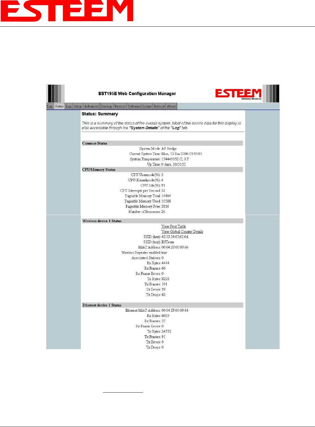
Status Menu
The Status Menu provides a summary of the current mode of operation, system time, processor usage, internal temperature and
status of the communication links to other wireless devices. An example is shown below in Figure 5. Most of the communication
troubleshooting is done in this section of the Web Configuration Manager.
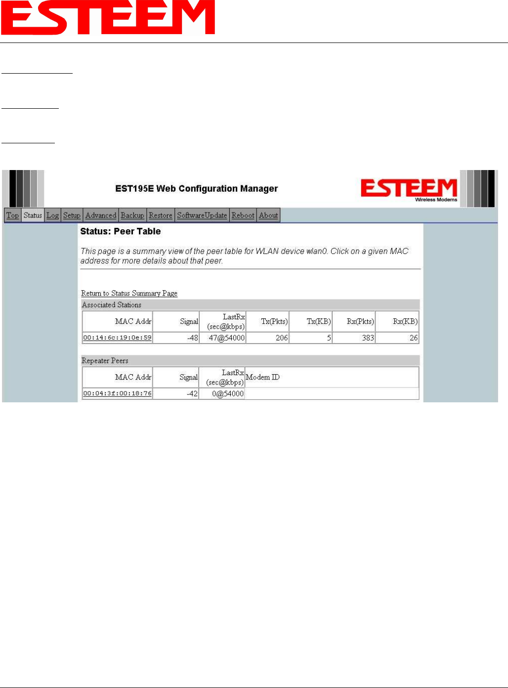
Peer Status Table
The Peer Status submenu lists the connected wireless devices (either Model 195Egs or 802.11g/b clients), their signal strength, data
rate and time of last packet sent. Press the View Peer Table link and Repeater Peer Status Table will be displayed (Figure 6). For a
detailed analysis of the information provided in this table, please review Appendix F – Troubleshooting.
Figure 5: Status Screen
CHAPTER 4
WEB CONFIGURATION
Revised: 21 Mar 08 4-4 EST P/N AA107G
Associated Station – This section will list all the associated stations that are attached to the Access Point. These could be other
Model 195Eg’s in one of the three Client modes or 802.11g/b devices.
Repeater Peers – This section will list all connected 195Eg repeater peers by their Wireless MAC address. For detailed information
on repeaters, see Chapter 6 – Repeating Features.
Access Points – This section will list all other 802.11g or 802.11b Access Points that are sharing the operating channel (frequency)
of the 195Eg. You can also note that the Repeater Peers listed above are also included in this list.
Counter Details
The Counter Details submenu will summarize all transmitted and receive data packets for the Model 195Eg (Figure 5).
Figure 6: Peer Table Screen
CHAPTER 4
WEB CONFIGURATION
Revised: 21 Mar 08 4-5 EST P/N AA107G
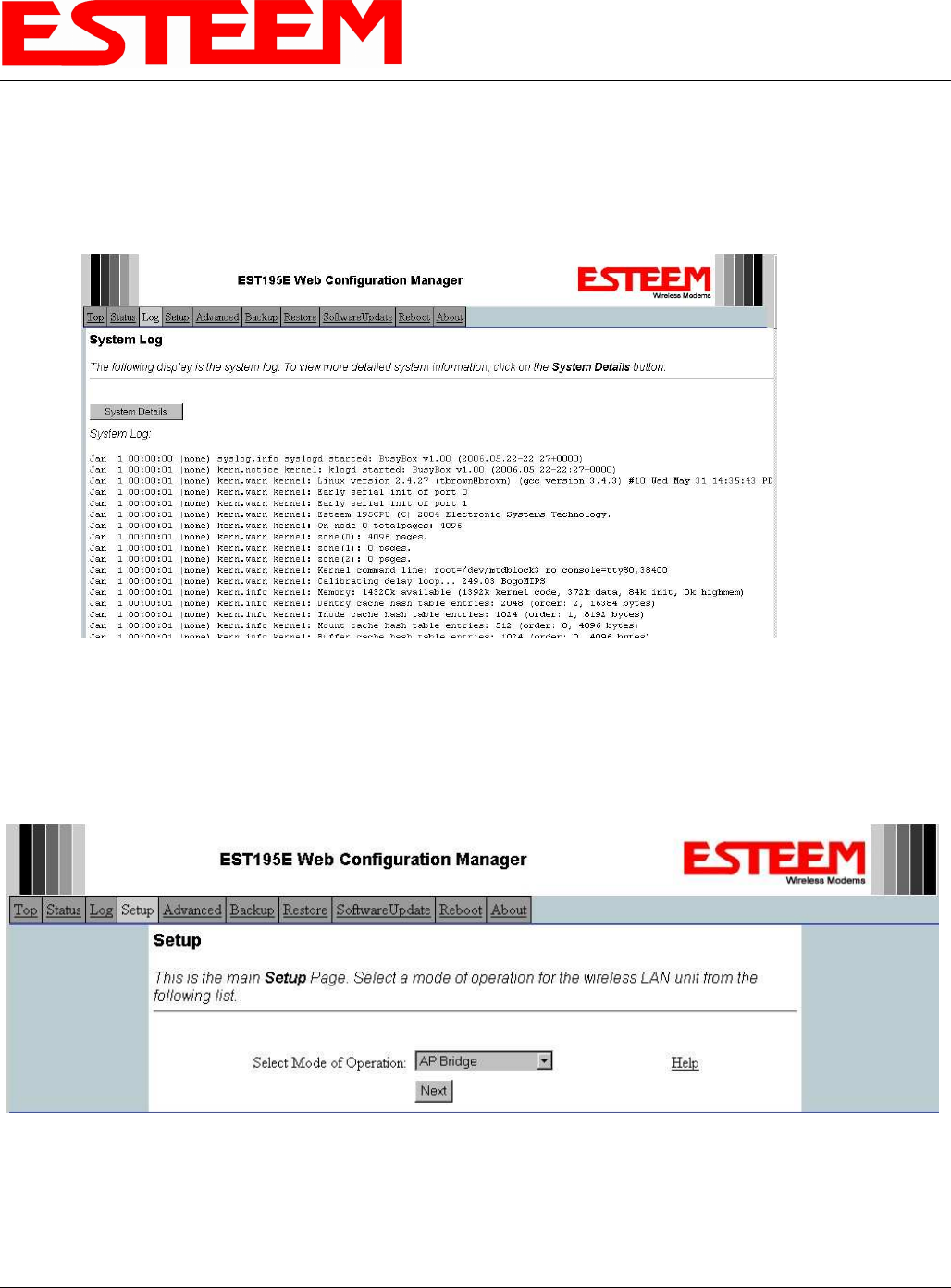
System Log Screen
The Log Screen is a trouble-shooting tool that shows the current log of Model 195Eg system messages. See Figure 7. The System
Details button will display a more detailed system diagnostics that may be requested by ESTeem technical support.
Setup Screen
The Setup screen allows the step-by-step configuration of the Model 195Eg. Please see Chapter 5 for complete description on
System Setup menu and examples for system configurations. See Figure 8.
Figure 7: System Log Screen
Figure 8: Setup Screen
CHAPTER 4
WEB CONFIGURATION
Revised: 21 Mar 08 4-6 EST P/N AA107G
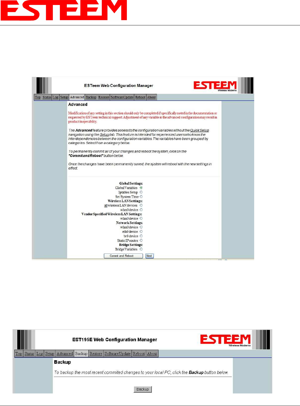
Advanced Configuration Screen
The Advanced screen allows the user to access all configuration parameters. The parameters are grouped based upon their variable.
It is recommended that only advanced users of the Model 195Eg enter this section unless instructed by ESTeem technical
support. See Figure 9.
Backup Screen
The Backup Screen saves the current configuration in the Model 195Eg to a file on the computer or network. See Figure 10.
Pressing the Backup Button will create a configuration file that can be saved to the computer. This saved file can then be later
opened, if necessary, by the Restore menu to quickly replace a Model 195Eg with a spare modem.
Figure 9: Advanced Features Screen
Figure 10: Backup Screen
CHAPTER 4
WEB CONFIGURATION
Revised: 21 Mar 08 4-7 EST P/N AA107G
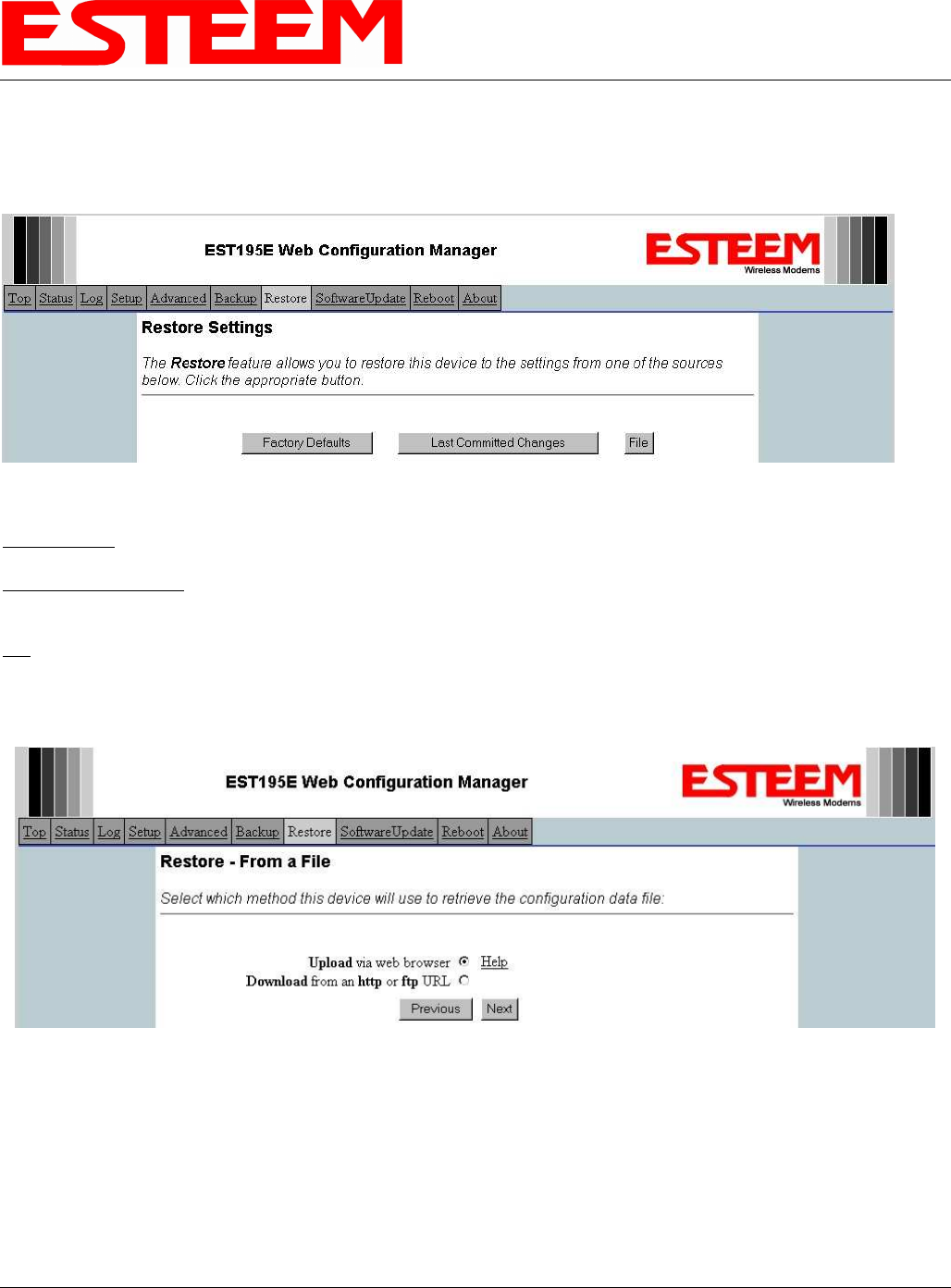
Restore Screen
The Restore screen is used to restore the 195Eg to factory defaults, return to the last saved configuration or to access the
configuration files that were backed up to the computer. See Figure 11.
Factory Default – Returns the Model 195Eg to all factory default values.
Last Committed Changes – This button will remove any changes to the modem that have been done since the last committed
changes. The last committed changes will be read from the Flash file and reset in the Model 195Eg.
File – Pressing this button will bring up a selection of where the restore file was saved during the Backup (Figure 12). Select
“Upload via web browser” to browse for files saved on a local computer or select “Download from an http or ftp URL” for files
saved on a network or over the Internet.
Figure 11: Restore Setting Screen
Figure 12: Restore From Local File Screen
CHAPTER 4
WEB CONFIGURATION
Revised: 21 Mar 08 4-8 EST P/N AA107G
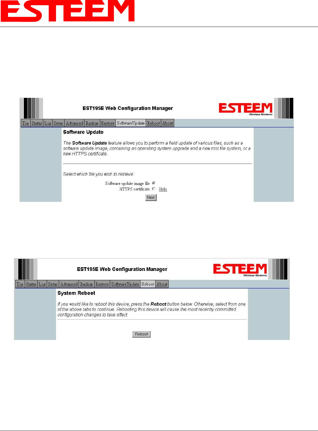
Software Update Screen
The Software Update feature allows the user to update the latest Model 195Eg operating system software from a file supplied by the
factory or the Internet to the Model 195Eg’s flash memory. To upload from a file on your computer, select Upload via web
browser and a file selection window will be displayed. To upload directly from the Internet, select Download from an http or ftp
URL and enter the site address. See Figure 13.
System Reboot Screen
The Reboot screen allows the user to reset the Model 195Eg. See Figure 14.
Figure 13: Software Update Screen
Figure 14: System Reboot Screen