Electronic Systems Technology ESTEEM195EG-1 ESTEEM 195Eg User Manual Chapter 0 Front Cover 195Eg
Electronic Systems Technology ESTEEM 195Eg Chapter 0 Front Cover 195Eg
Contents
user manual apx C to H
APPENDIX C
INTERFACE PORTS
Revised: 23 Jan 08 APX C-1 EST P/N AA107G
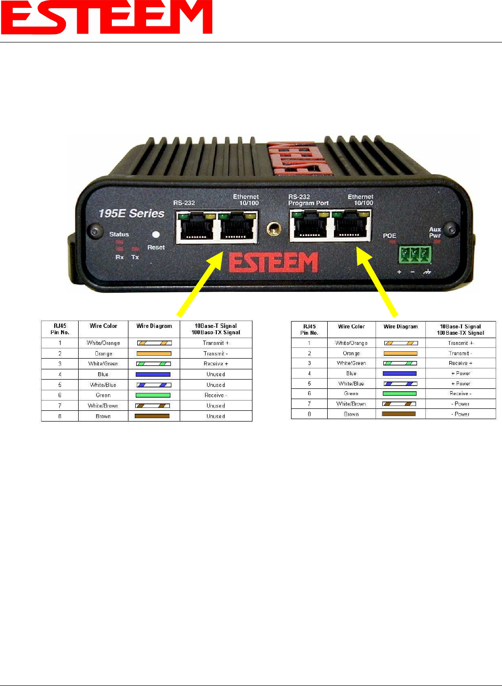
ETHERNET INTERFACE
The ESTeem Model 195Eg’s Ethernet Port is a Full and Half-Duplex Auto-negotiation interface supporting both 10 Mbps and 100
Mbps (10/100BaseT). The Ethernet port is compliant with IEEE 802.3af Power Over Ethernet (PoE) to provide both data and
power over the same CAT-5E grade Ethernet cable. The port is compatible with TIA/EIA-568B cable configuration (Figure 1).
A second Ethernet port will be included if the serial option is added to the 195Eg. This second Ethernet port can be used in Bridge
Mode (HUB) or as a router.
Figure 1: Ethernet Pin Layout
APPENDIX C
INTERFACE PORTS
Revised: 23 Jan 08 APX C-2 EST P/N AA107G
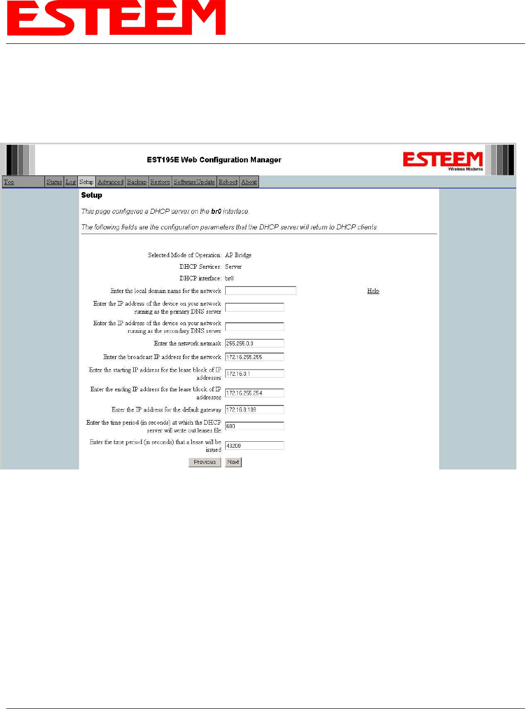
CONFIGURING DHCP SERVER
The ESTeem 195Eg Ethernet port supports both client and server Dynamic Host Configuration Protocol (DHCP). Figure 2 shows
the DHCP host configuration screen that will be shown if DHCP server is selected in the setup screens. Enter the values that match
the DHCP configuration for your network.
Figure 2: DHCP Server Configuration
APPENDIX C
INTERFACE PORTS
Revised: 23 Jan 08 APX C-3 EST P/N AA107G
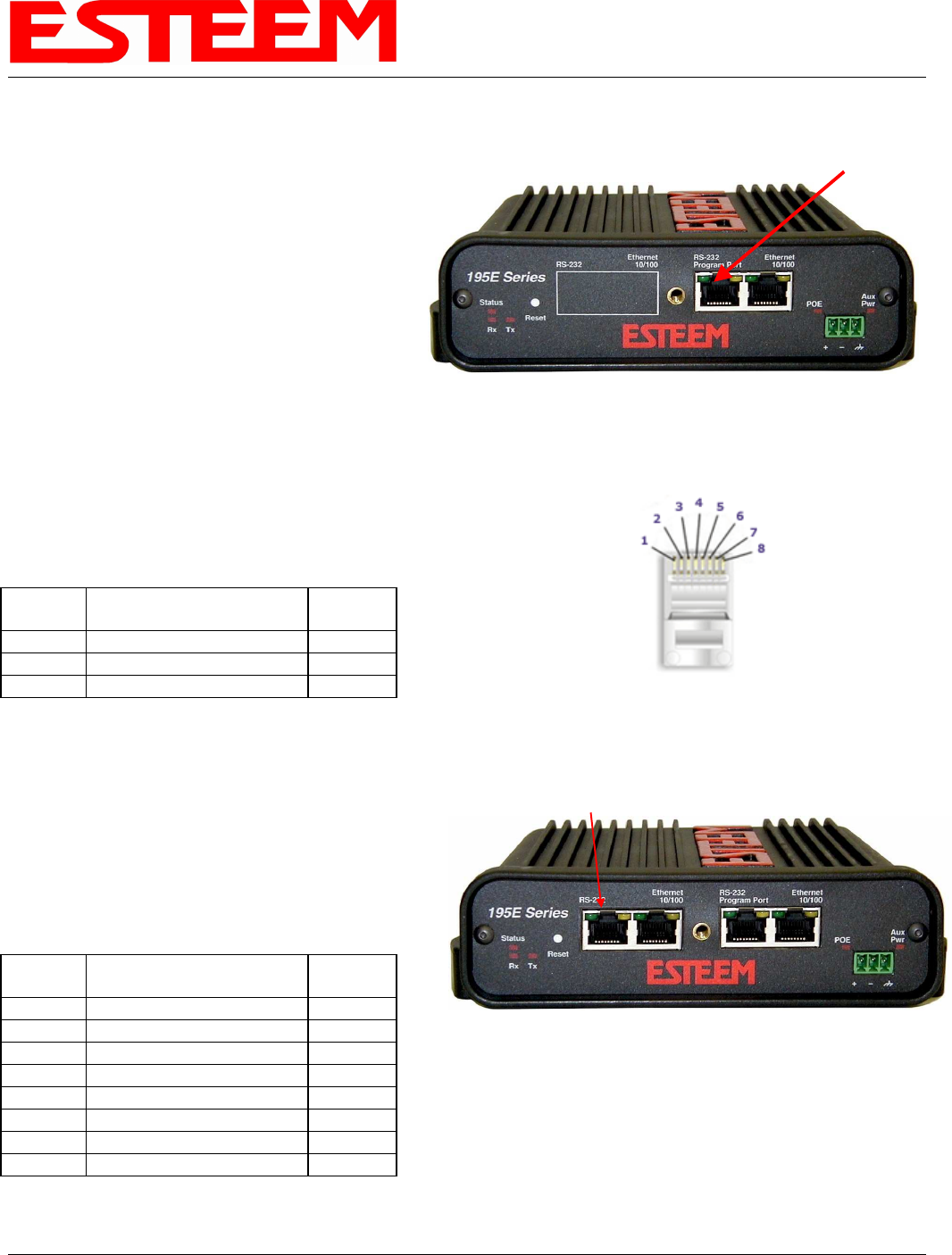
RS-232C PROGRAMMING PORT
CONFIGURATION
The ESTeem Model 195Eg has a proprietary RS-232C
interface in a RJ-45 connector on the front panel. To
interface the 195Eg to the serial port on the computer,
you need ESTeem cable AA0621 that combines a
standard Ethernet patch cable to a 9-pin Female adapter.
The serial port on the ESTeem Model 192E can be used
to access the configuration menu in the ESTeem for
system and network configuration. The ESTeem
communications port operates at 38,400 bps, No Parity, 8
Data Bits and 1 Stop Bit (38,400,N,8,1). Configure your
terminal program to match these settings.
RS-232 PROGRAMMING PORT PIN-OUT TABLE
ESTeem Model AA0621
RS-232C Port Pin-Out Table
RJ-45
Pin No. Function
DB-9
Pin No.
4 Signal Ground (GND) 5
5 Receive Data (RxD) 2
6 Transmit Data (TxD) 3
RS-232C DATA PORT CONFIGURATION
The ESTeem Model 195Eg has an RS-232C interface in a
RJ-45 connector on the front panel that can be installed as
an option . To interface the 195Eg to the serial port on the
computer, you need serial cable with the following pin-out:
ESTeem Model AA0621
RS-232C Port Pin-Out Table
RJ-45
Pin No. Function
DB-9
Pin No.
1 Data Set Ready (DSR) 6
2 Data Carrier Detect (DCD) 1
3 Data Terminal Ready (DTR) 4
4 Signal Ground (GND) 5
5 Receive Data (RxD) 2
6 Transmit Data (TxD) 3
7 Clear to Sent (CTS) 8
8 Request to Sent (RTS) 7
RS-232
Programming Port
Model 195Eg Serial Port Interface
Ethernet Pin-out
RS-232
Data Port
Model 195Eg Serial Data Port Interface
APPENDIX D
RADIO CONFIGURATION
Revised: 18 Mar 08 APX D-1 EST P/N AA107G
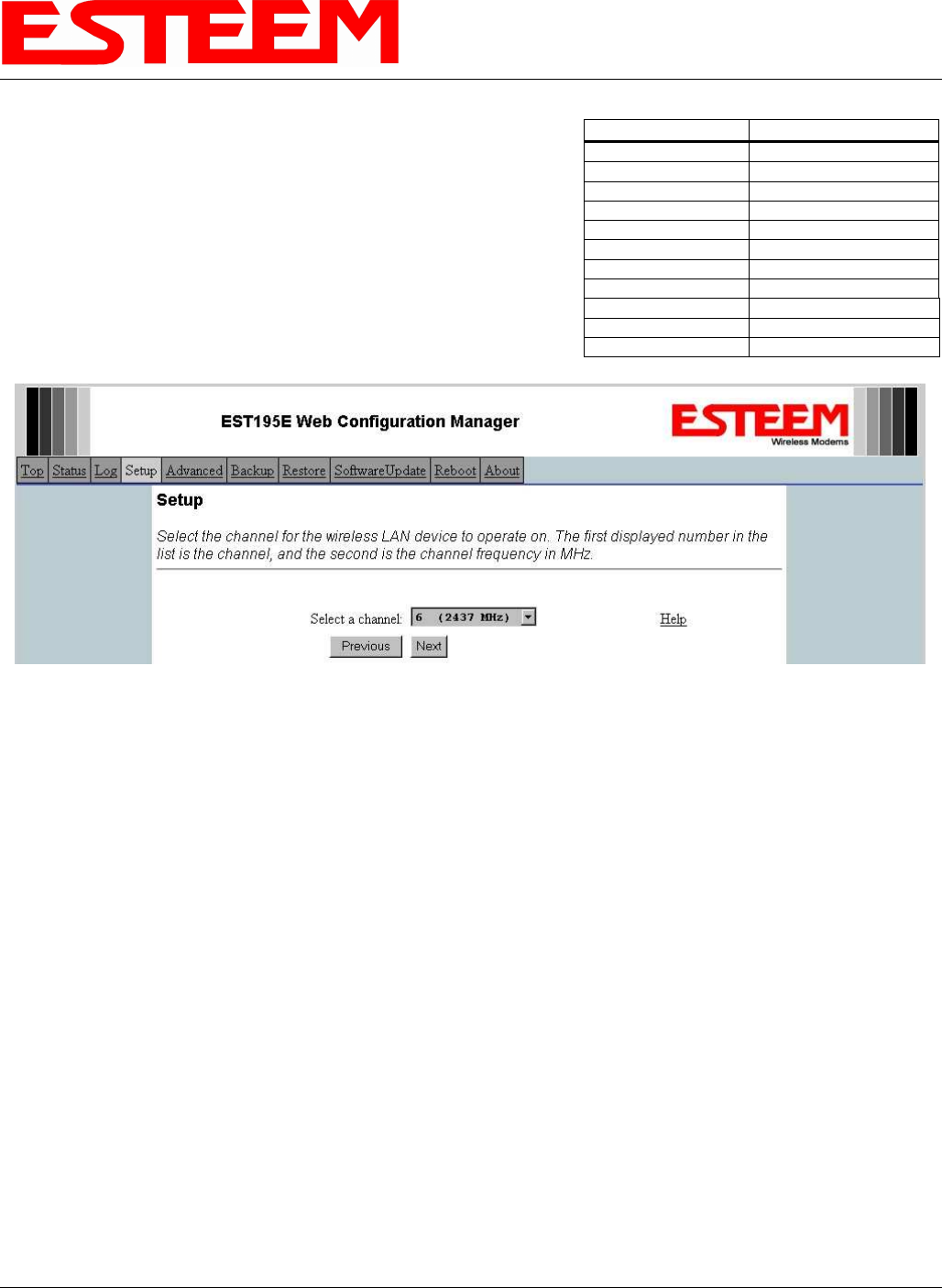
195Eg FREQUENCY OF OPERATION
In a wireless Ethernet network all of the ESTeem Model 195Eg’s must be set
to the same radio frequency of operation or channel. Listed on the right is a
table showing the channel and corresponding frequency of operation. The
frequency of operation is selectable when configuring the mode of operation of
the 195Eg (reference Chapter 4). See Figure 1.
RF COMMUNICATIONS DATA RATE
The RF data rate of the Model 195Eg can be programmed for operation at 1, 2, 5.5, 6, 9, 11, 12, 18, 24, 36, 48, or 54 Mbps. The
RF data rate can be set for a fixed rate or a specific range that is dynamically scaled by the Model 195Eg from monitoring the
received signal quality. The Model 195Eg can communicate with multiple 802.11g devices at different data rates for each device.
By selecting all ranges from 1 to 54 Mbps you will be able to communicate with all 802.11g and 802.11b devices regardless of their
generation, data rate, and signal quality requirements.
Dynamic scaling means that the Model 195Eg will operate at the highest RF data rate that is programmed into unit. If the received
data quality drops below the required minimums for reliable communications the Model 192E will reduce the data rate to the next
lowest step to increase signal quality. Conversely if the signal quality increases above the minimums the Model 192E will increase
the RF data rate the next highest level.
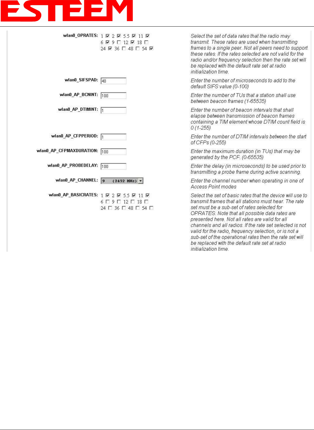
The ESTeem 195Eg is set at the factory to operate at maximized scaling speed data rates from 1-54 Mbps and should not need
adjustment. The RF Data Rate is programmed in the Model 195Eg through the Advanced Menu>Wireless LAN Settings>Wlan0
Device and the value for wlan0_OPRATES:. In the example shown in Figure 2 the RF Date Rate is programmed to dynamic scale
from 1 to 54 Mbps (recommend factory default setting). To set the values for the data rate, check the box next to the listed data rate
to enable this rate for operation.
Figure 1: RF Channel Selection
Channel Number Frequency
1 2412 MHz
2 2417 MHz
3 2422 MHz
4 2427 MHz
5 2432 MHz
6 2437 MHz
7 2442 MHz
8 2447 MHz
9 2452 MHz
10 2457 MHz
11 2462 MHz
APPENDIX D
RADIO CONFIGURATION
Revised: 18 Mar 08 APX D-2 EST P/N AA107G
RF BASIC RATE
The RF Basic Rate is the synchronization rate used to establish the initial connection between 802.11g and 802.11b communication
devices in Mbps. After the initial connection has been establish the RF communication rate will be determined by the RF
Communication Data Rate established above. Factory default is 1 through 11 Mbps shown in Figure 2 so that the unity will
establish communication with the older (slower) 802.11b devices. This lower rate also allows for a quicker reconnect when the
ESTeems are configured for EtherStation mode or working in a mobile environment.
The ESTeem 195Eg is set at the factory to operate at all speeds from 1-11 Mbps and should not need adjustment. The RF Basic
Rate is programmed in the Model 195Eg through the Advanced Menu>Wireless LAN Settings>Wlan0 Device and the value for
wlan0_AP_BASICRATES:. In the example shown in Figure 2 the RF Date Rate is programmed to dynamic scale from 1 to 11
Mbps (recommend factory default setting). To set the values for the data rate, check the box next to the data rate required.
Note: The Model 195Eg will only communicate with slower speed devices after synchronization if the RF Communication Data
shown above has been set to dynamically scale to 1 and 2 Mbps.
In general, do not set the RF Basic Rates above 11Mbps unless specifically instructed by ESTeem Customer Support.
Figure 2: Advanced Data Rate Selection
APPENDIX D
RADIO CONFIGURATION
Revised: 18 Mar 08 APX D-3 EST P/N AA107G
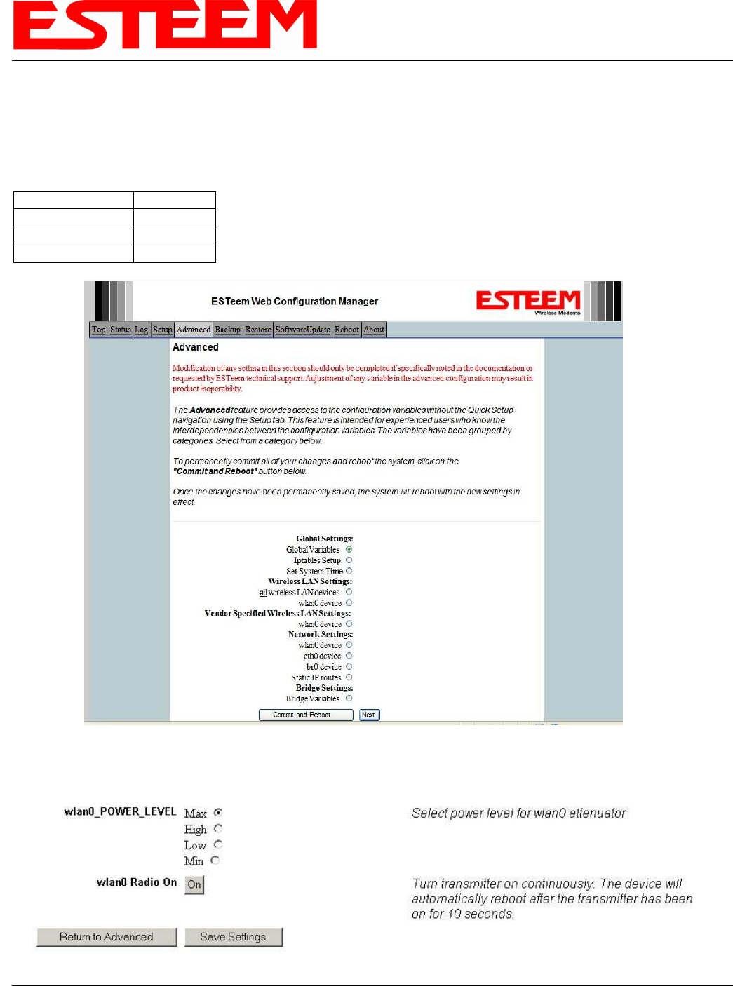
SETTING RF POWER LEVEL
The ESTeem Model 195Eg peak power is adjustable in output power from 250mW to 1 Watt. The output power is adjusted on the
Advanced Menu>Wireless LAN Settings>Wlan0 Device screen (Figure 3) of the Web Configuration Manager. Select the value
and press the Save Settings button.
Max (Maximum) 1 Watt
Hi (High) ≈700 mw
Lo (Low) ≈500 mw
Min (Minimum) ≈250 mw
Figure 4: Power Level Settings
Figure 3: Advanced Global Variables

APPENDIX D
RADIO CONFIGURATION
Revised: 18 Mar 08 APX D-4 EST P/N AA107G
AVERAGE RF OUTPUT POWER
The average measurable output power on the ESTeem Model 195Eg will vary from 24dBm to 30dBm depending upon modulation
type and RF data rate. The average power is used when entering the output power level in the ESTeem RF Design program. The
following table provides that level and modulation type at each data rate:
RF Data Rate (Mbps) Average Power Modulation Type
1 30dBm BPSK
2 30dBm BPSK
5.5 30dBm BPSK
6 30dBm OFDM
9 30dBm OFDM
11 30dBm BPSK
12 28dBm OFDM
18 28dBm OFDM
24 27dBm OFDM
36 27dBm OFDM
48 24dBm OFDM
54 24dBm OFDM

APPENDIX E
SECURITY
Revised: 23 Jan 08 APX E-1 EST P/N AA107G
OVERVIEW
The security for the ESTeem Model 195Eg, like all network security, must be multi-layered. One level of security is never enough
to make sure that data does not end up in the wrong hands. Please review the following security levels and decide what is the most
appropriate for your network.
128-BIT WEP
The 128 WEP uses a particular algorithm called RC4 encryption to encode and decode traffic that is based on a 104-bit encryption
key and a 24-bit Initialization Vector (IV). RC4 starts with a relatively short encryption key (104 bits) that is expanded into a
nearly infinite stream of keys to accompany the stream of packets.
The basic concept of RC4 is good, but the way it’s implemented in WEP leaves it open to compromise. The researchers that test
the integrity of the system usually focus on one piece of the implementation, the Initialization Vector (IV).
The IV (24 bits) is the algorithm component that’s supposed to keep expanded keys from repeating. From the researcher’s point of
view, a high-volume access point is mathematically guaranteed to reuse the same key stream at least once a day. When this
happens, it’s called an IV collision this becomes a soft spot to enter the system.
The researchers aren’t saying that it’s easy to break into the system, or that it’s being done on a regular basis, only that it is possible
and that administrators should consider ways to reduce the possibility.
WPA
Wi-Fi Protected Access with Preshared Key (WPA PSK)
WPA, which uses 802.1x, was introduced in 2003 to improve on the authentication and encryption features of WEP. All
authentication is handled within this access point device. WPA has two significant advantages over WEP:
1. An encryption key differing in every packet. The TKIP (Temporal Key Integrity Protocol) mechanism shares a starting
key between devices. Each device then changes their encryption key for every packet. It is extremely difficult for hackers
to read messages even if they have intercepted the data.
2. Certificate Authentication (CA) can be used, blocking a hacker posing as a valid user.
Wi-Fi Protected Access with Enterprise Server (WPA Enterprise)
Like WPA PSK, WPA Enterprise uses 802.1x. However, a backend authentication server handles the authentication decision. The
most commonly type of authentication server is a RADIUS server. The ESTeem Model 195Eg can be configured to operate with
an established RADIUS server on the network.
WPA is server/client relationship from a software driver on a computer’s wireless LAN (WLAN) card to an Access Point. The
scope of WPA is limited in use to this configuration only. The ESTeem Model 195Eg can support WPA Enterprise and PSK as an
Access Point, but the level of security on the Bridging layer is configured separately.
ACCESS CONTROL LIST (ACL)
The ACL is one of the simplest yet most secure methods of network security. The ACL is a configurable MAC filter in the Model
192E that can be set to allow specific MAC address on the wireless network by individual address or address ranges. The same
filter can also be set to reject individual MAC addresses or address ranges.
The MAC address is a unique, 6 hexadecimal field address assigned at the manufacturer that can not be changed. The MAC
address is traceable through the IEEE governing body to the manufacturer and is the “fingerprint” for all Ethernet devices.

APPENDIX E
SECURITY
Revised: 23 Jan 08 APX E-2 EST P/N AA107G
Using a combination of both the WPA or 128-Bit WEP encryption and the ACL filter provide the ESTeem an extremely secure
wireless networking layer.
DISABLING BROADCAST PROBES AND HIDING SSID
A simple but very effective way of securing a network is to make the network difficult to find. By disabling broadcast probes and
hiding the Service Set Identification (SSID), wireless and network “sniffers” will not be able to find your ESTeem Model 195Eg
network. To gain access to the wireless network, you would be required to have the SSID and all security loaded in the WLAN
card software prior to entering the network.
PROPRIETARY BRIDGE COMMUNICATION
Although the ESTeem Model 195Eg is compatible with the open communication standards IEEE 802.11g and 802.11b, the
repeater communication between the units is a proprietary communication link. No other manufacturer of wireless hardware can
access the ESTeem repeater network when bridging between Ethernet networks. This proprietary communication layer, in
combination with the other security settings, allows you as the user to reject wireless clients into the network if so desired. When
used in conjunction with the Access Control List the 802.11g and 802.11b client access can be removed.
The security level of the bridge communication link is configurable for 64-Bit WEP, 128-Bit WEP or TKIP and is completely
independent of the client access level or any other communication link level. For example, an ESTeem Model 195Eg can be
configured for WPA Enterprise for client level access, communicate to another ESTeem Model 195Eg using a TKIP bridge link
and also communicate 128-Bit WEP to our older ESTeem Model 192E radio modems all running simultaneously.
MASQUERADE MODES
When the ESTeem Model 195Eg is configured in either the Access Point Masquerade or the Client Masquerade modes, the
wireless modem functions as a network firewall. If access to the wired network is the greatest concern, place the ESTeem in the
Masquerade mode and the wireless network will be completely isolated from the wired Ethernet network.
INCREASING NETWORK SECURITY
The following are a few suggestions to help improve the overall security of your wireless network:
1. Enable the security. If you research all of the articles regarding hackers, they have gotten into the user’s network due to the
security not being enabled.
2. Set the ACL filter to include only those MAC address of the wireless Ethernet device being used on the network.
3. Set "Hide SSID" to True. As you take your access point out of the box, broadcast SSID is enabled which means that it will
accept any SSID. By hiding the SSID configured in the client must match the SSID of the access point.
4. Make sure the keys are not reused in your company, since reuse increases the statistical likelihood that someone can figure the
key out and change the default password on your access point or wireless router
5. Change the default SSID of your product. Don't change the SSID to reflect your company's main names, divisions, or products.
It just makes you too easy to target.
6. As a network administrator, you should periodically survey your company using a tool like NetStumbler to see if any "rogue"
access points pop up within your company without authorization. All of your hard work to "harden" your wireless network
could be wasted if a rogue AP was plugged into your network behind the firewall.

APPENDIX E
SECURITY
Revised: 23 Jan 08 APX E-3 EST P/N AA107G
7. Many access points allow you to control access based on the MAC address of the NIC attempting to associate with it. If the
MAC address of your NIC isn't in the table of the access point, you won't associate with it. And while it's true that there are
ways of spoofing a MAC address that's been sniffed out of the air, it takes an additional level of sophistication to spoof a MAC
address. The downside of deploying MAC address tables is that if you have a lot of access points, maintaining the tables in
each access point could be time consuming. Some higher-end, enterprise-level access points have mechanisms for updating
these tables across multiple access points of the same brand.
8. Consider using an additional level of authentication, such as Remote Access Dailin User Service (RADIUS), before you permit
an association with your access points. While it's not part of the 802.11b standard, a number of companies are optionally
including some provision for RADIUS authentication.
9. If you're deploying a wireless router, think about assigning static IP addresses for your wireless NICs and turn off Dynamic
Host Configuration Protocol (DHCP). If you're using a wireless router and have decided to turn off DHCP, also consider
changing the IP subnet. Many wireless routers default to the 192.168.1.0 network and use 192.168.1.1 as the default router.
10. Don't buy Access Points or NICs that only support 64-bit WEP.
11. Only purchase Access Points that have flashable firmware. There are a number of security enhancements that are being
developed, and you want to be sure that you can upgrade your access point.
12. A simple security technique used by the military is to have the administrator periodically change the key for the system i.e.
weekly, monthly, etc.
APPENDIX F
TROUBLESHOOTING
Revised: 23 Jan 08 APX F-1 EST P/N AA107G
TESTING COMMUNICATION LINK
After you have configured at least two of the Model 195Eg wireless Ethernet modems for operation, you can verify communication
with each the following steps:
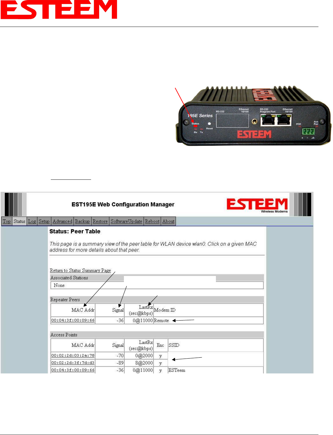
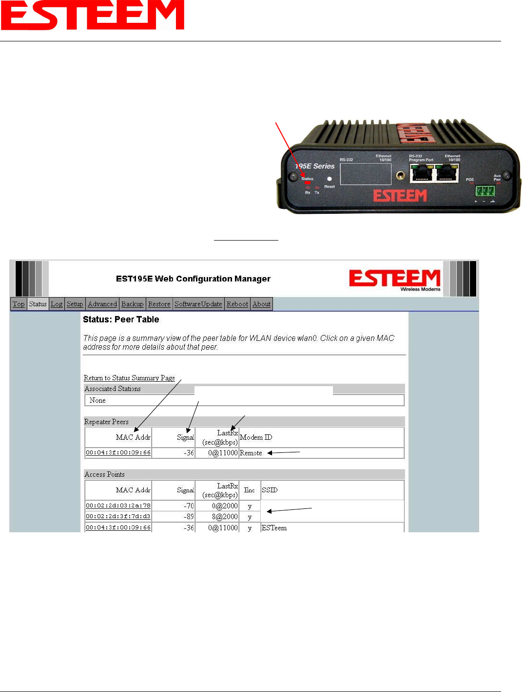
Status Light
The quickest source of link status is to view the Status Light
on the face of the 195Eg (Figure 1). If the Status light is
solid, the Model 195Eg has a connection to another Model
195Eg listed in the Peer Table.
Status Screen/Peer Table
To view detailed information on the status of the
communication link (such as connection speed, signal
strength and last update time) you can open the Status Screen from the Web Interface. After press the Status tab at the top of the
screen the Status: Summary will be displayed showing the status of all ports and memory in the 195Eg. Under the Wireless Status
heading click on the View Peer Table (Figure 2). The Peer Table will list all other 802.11b or 802.11g wireless activity seen by the
195Eg and how it is classified.
Note: The data rate displayed is not necessarily indicative of the RF data rate between the ESTeems. The rate show in the
Repeater Peer table will be the last RF packet, which could consist of either data, repeater beacon or network probes.
Status LED
Solid Red on Link
Figure 1: Connection Status Light
Opposite Modem’s Wireless MAC
Receive Signal Strength (dBm)
Last Packet Received
Peer Modem ID
Other Access Points
Figure 2: Repeater Peer Table
APPENDIX F
TROUBLESHOOTING
Revised: 23 Jan 08 APX F-2 EST P/N AA107G
Repeater Peers - The Peer Table will display all connected 195Egs configured to repeat to this ESTeem by their Wireless (WLAN)
MAC address.
Received Signal Strength – This is the first of the two numbers listed in the block. This signal strength value is listed in dBm.
Last RX – This is the time of the last received data packet. When monitoring the status menu, it is important to note the time the
last transmission was updated so you are not looking at “stale” data.
Current Data Rate – This is the current speed the last data packet received by the Model 195Eg. This may not be the data rate
between the radio modems. Note that the speed is listed in kbps, so that 11000 kbps is equal to 11 Mbps.
Note: The ESTeem Model 195Eg uses spread spectrum technology that analyzes each data packet for signal strength and data
quality (strength vs. noise). The higher your signal, the mare background noise you can sustain without causing degradation in
the data transfer. This is also true for lower signal strengths with a very low background noise. These values are provided for
guidance and if you have any questions about the values in your application, please contact ESTeem Customer Support at 509-
735-9092 or e-mail your application to support@esteem.com.
Modem ID – This is Modem ID for the opposite repeater peer.
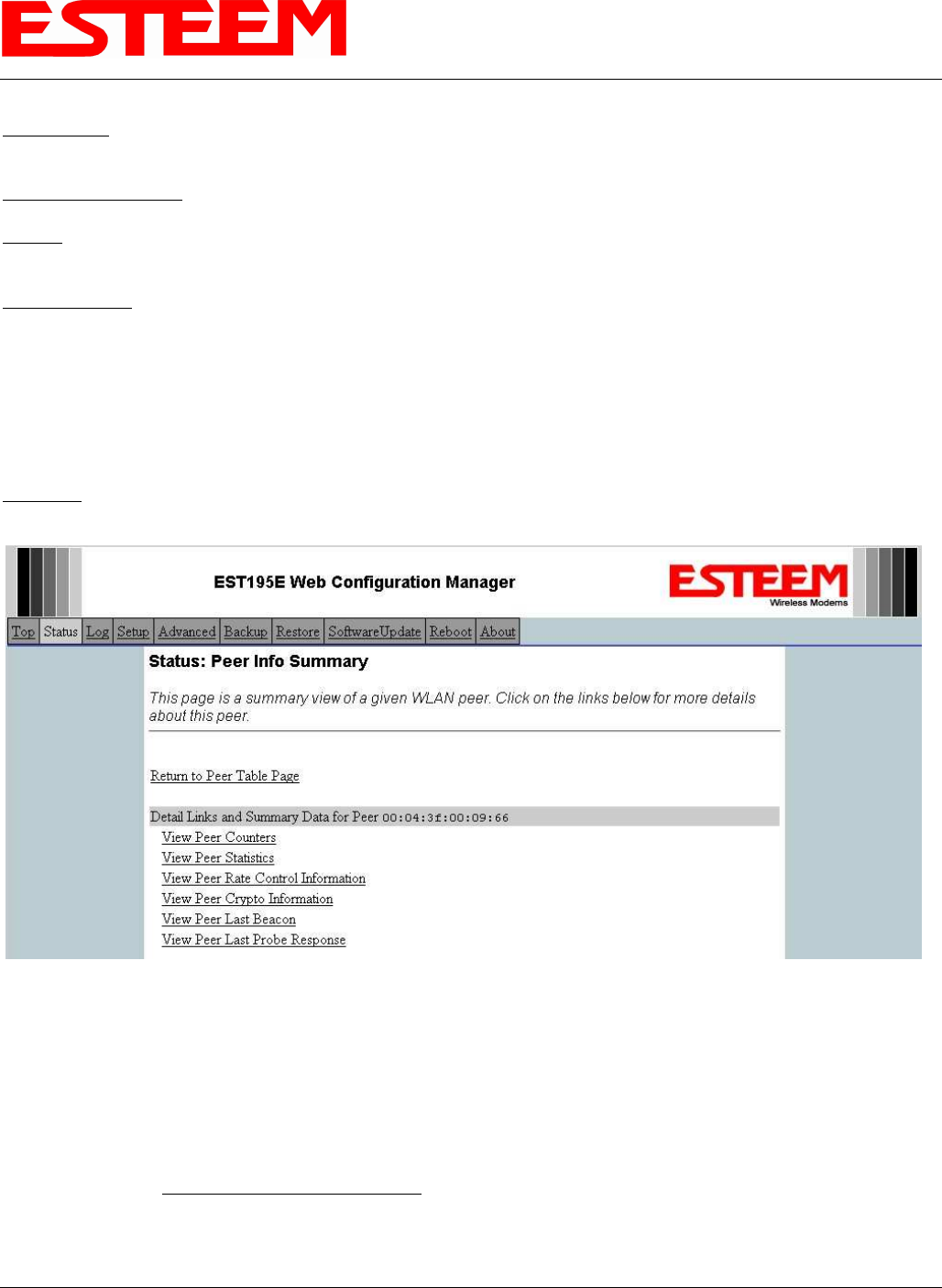
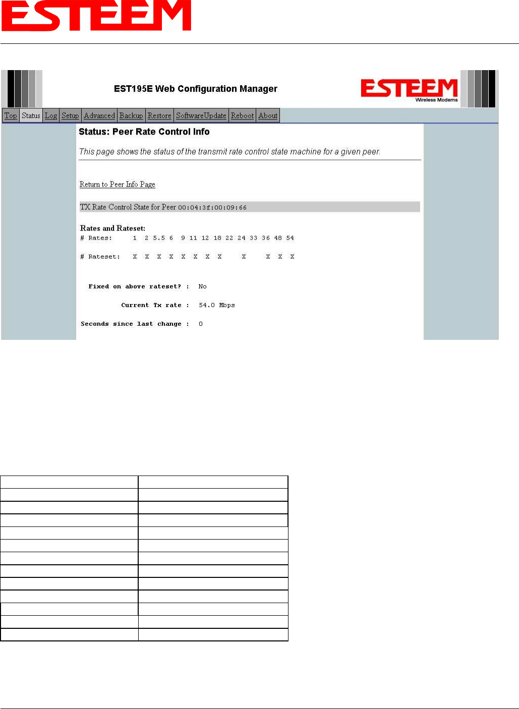
Viewing RF Data Rates
The value shown on the Peer Status Screen for data rate may not be the actual rate of the RF link. To view the link information,
click on the Opposite Modems WLAN MAC address in the Repeater Peer list (Figure 2) and further link status information will be
displayed (Figure 3).
Once loaded, click on View Peer Rate Control Information. (Figure 4)
Figure 3: Peer Summary Table
APPENDIX F
TROUBLESHOOTING
Revised: 23 Jan 08 APX F-3 EST P/N AA107G
The value of the Current TX rate is the RF data rate between the two ESTeem Model 195Eg.
SIGNAL STRENGTH VS DATA RATE
The following chart will show the average signal strength required to maintain a data rate. Please note that the data rates listed here
can be greatly effected by overall activity on the radio channel and the total background noise. This values should be used as a
guide, but testing after installation is required.
Receive Signal Strength RF Data Rate
-89 dBm 1 Mbps
-86 dBm 2 Mbps
-85 dBm 5.5 Mbps
-88 dBm 6 Mbps
-87 dBm 9 Mbps
-82 dBm 11 Mbps
-84 dBm 12 Mbps
-82 dBm 18 Mbps
-79 dBm 24 Mbps
-75 dBm 36 Mbps
-70 dBm 48 Mbps
-68 dBm 54 Mbps
Note: The signal strength required for the above data rates are effected by other RF transmitters in the area. A higher signal
strength will be required in applications with high background noise.
Figure 4: Rate Control Information
APPENDIX F
TROUBLESHOOTING
Revised: 23 Jan 08 APX F-4 EST P/N AA107G
UPDATING MODEL 192E TO OPERATE WITH 195EG
The ESTeem Model 192E can be used in a Model 195Eg system but does require an update to the firmware. Once the 192E
firmware has been updated, all the programming instructions in this User’s Manual will be applicable. The following firmware
update procedure requires the ESTeem 192E to first be updated to firmware version 220.19. Once this has been verified, please
proceed.
Local FTP Server
1. Configure an FTP server on the network where the ESTeem Model 192E is connected. Verify that you have anonymous access
to the FTP server before proceeding.
2. Download the following files from the ESTeem FTP Site (ftp://www.esteem.com/192E).
a. 192eupdate.sh
b. 192epdrs.sh
c. swupdate-192e-230.dev.65.img
d. DOS2UNIX.EXE
3. Open the 192eupdate.sh file using Wordpad. Replace <server-IP> with the IP of your ftp server. Replace <version> with the
firmware version (e.g., 230.dev). For example:
4. Save the amended script file.
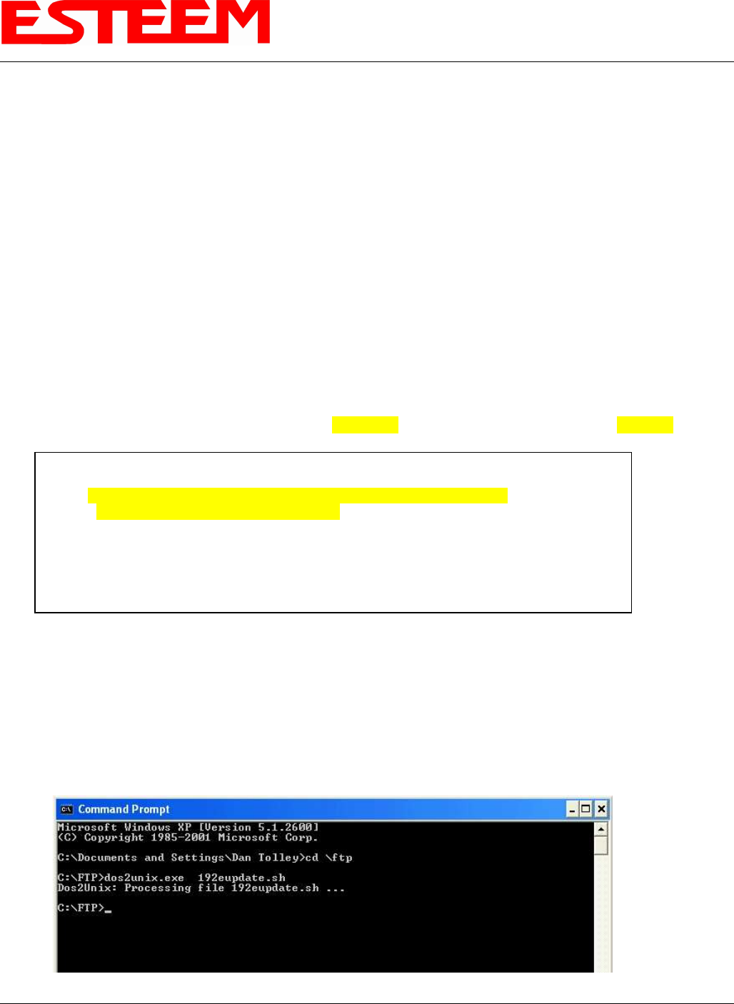
5. Open a Command Prompt.
a. Open the directory where the files have been saved and type the following:
C:\<directory>dos2unix.exe 192eupdate.sh
You will then see the following string:
Dos2Unix: Processing file 192eupdate.sh…
Example:
Figure 5: DOS Command Display
mkdir /var/update
cd /etc
wget ftp://172.16.252.251/ swupdate-192e-230.dev.65.img
dd if= swupdate-192e-230.dev.65.img of=/dev/ram0
mount /dev/ram0 /var/update
cd /var/update
/sbin/dkflash -v -d -w -o 0x00040000 kernel.img
/sbin/dkflash -v -d -w -o 0x00140000 rootfs.img
/sbin/reboot
APPENDIX F
TROUBLESHOOTING
Revised: 23 Jan 08 APX F-5 EST P/N AA107G
6. Using an Internet Explorer or other web browser, open the internal WebPage of the local ESTeem192E you wish to upgrade. A
hardwired Ethernet connection to the modem is required.
7. Configure the 192E in the Ethernet Only mode, make changes permanent and reboot.
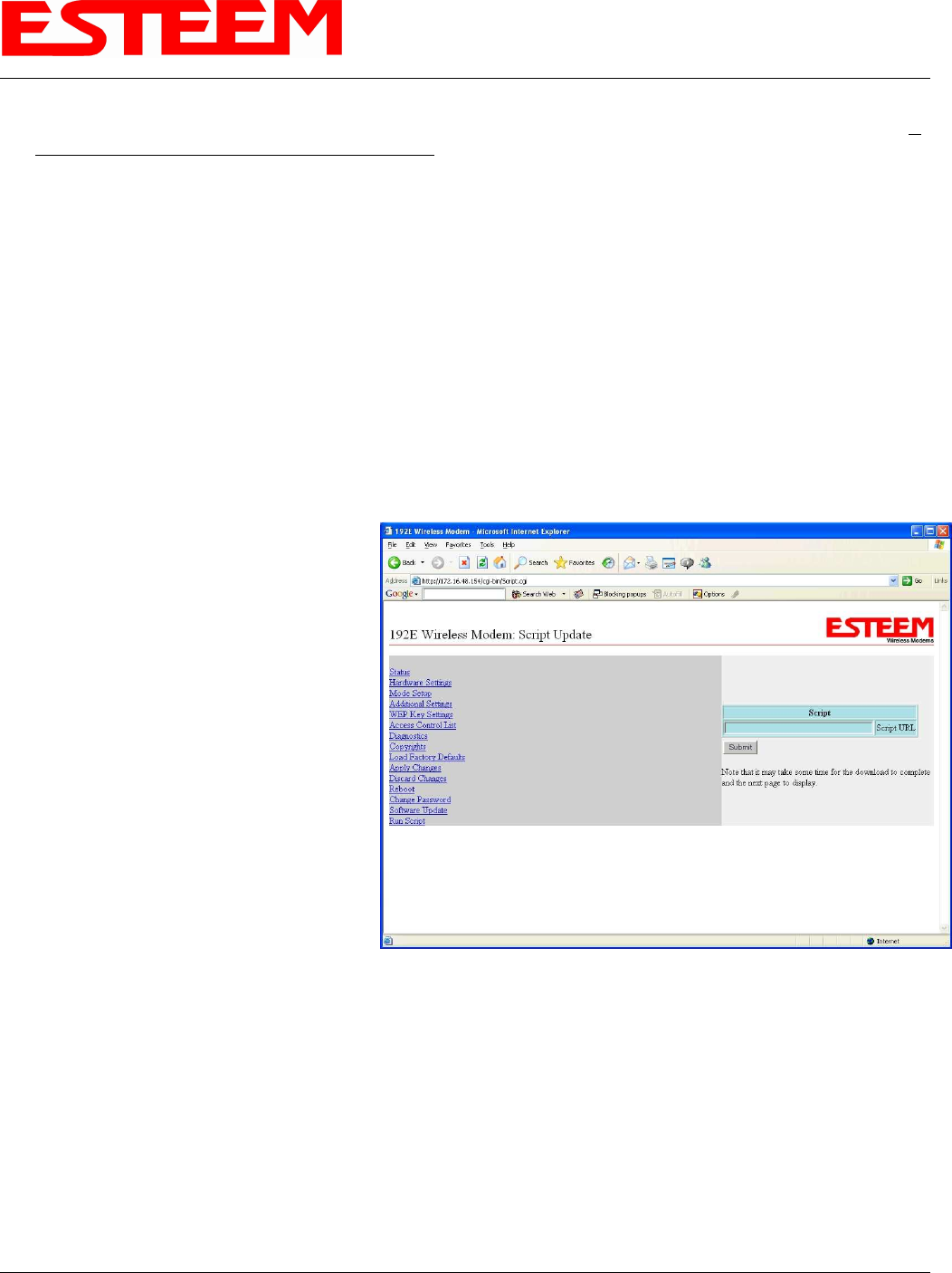
8. Choose Run Script
9. When prompted for the script URL input the following command string and submit:
ftp://<IP Address of FTP Server>/192epdrs.sh>
Example: ftp:// 172.16.1.1/192epdrs.sh
10. The modem will download and execute the firmware update. After the log file is displayed, configure the 192E in the Access
Point mode, make changes permanent and reboot.
11. Choose Run Script
12. When prompted for the script URL input the following command string and submit:
ftp://<IP Address of FTP
Server>/192eupdate.sh>
Example: ftp:// 172.16.1.1/192eupdate.sh
13. While the script is running, the 192E will not
respond and the browser will time out. Close
the browser window to refresh the path the
192E.
14. Please wait approximately 5 minutes before
opening a new Internet Explorer browser to
access the internal WebPages. Enter the IP
address of the local ESTeem 192E to access
the updated unit. The ESTeem 192E can now
be reconfigured for use. Please refer to the
ESTeem 195Eg Owner’s Manual for details.
If you do not have one, please download from
the ESTeem FTP site at the following:
ftp://ftp.esteem.com/195Eg/AA107G Manual
195Eg.
Figure 6: Script Input
APPENDIX F
TROUBLESHOOTING
Revised: 23 Jan 08 APX F-6 EST P/N AA107G
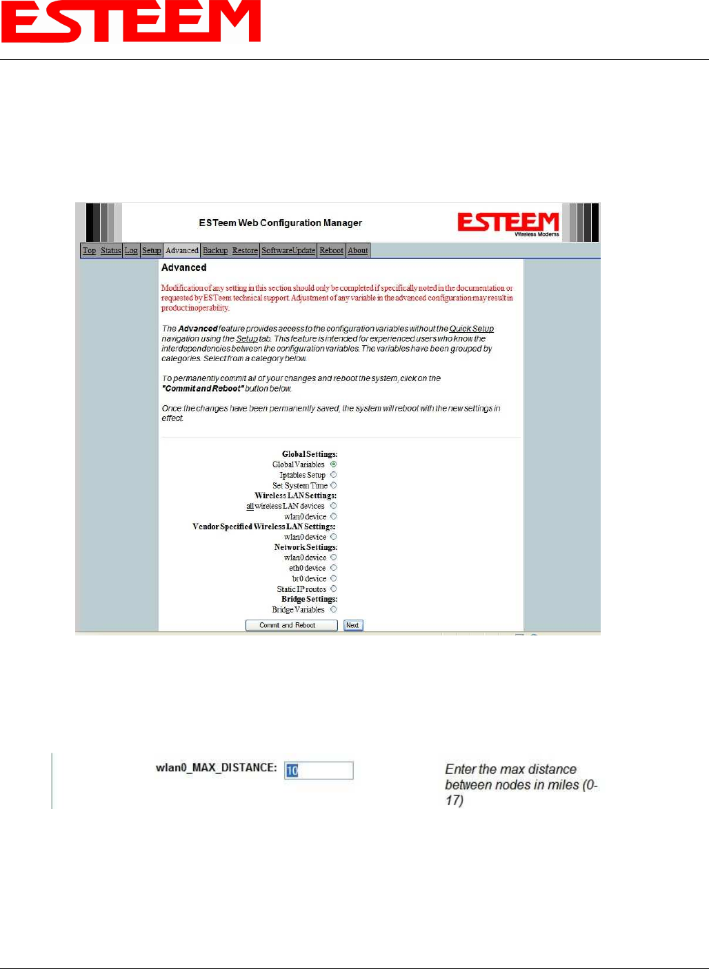
LONG RANGE POINT TO POINT APPLICATIONS
The factory configuration on the 195Eg is optimized for distances up to 10 miles. If your application has an RF link with a range
greater than 10 miles, you will need to set the maximum range value on both ESTeem 195Eg’s on this communication link. To
access the Maximum Distance value select Advanced from the top Menu then Wireless LAN Settings>wlan0 device and press
the Next button (Figure 7).
Scroll down the menu list until you find the Maximum Distance variable (Figure 8). Enter the maximum distance of the connection
in miles. At the bottom of the screen press Return to Advanced button and then Commit and Reboot button (Figure 7) to save
the information.
Figure 7: Advanced Features Screen
Figure 8: Maximum Distance Value Entry

APPENDIX F
TROUBLESHOOTING
Revised: 23 Jan 08 APX F-7 EST P/N AA107G
TROUBLESHOOTING TIPS
General (Applicable to All Modes of Operation)
Where do I find the latest firmware version number? – We have the latest version number of the Model 195Eg firmware listed on
the ESTeem Web site (www.esteem.com) under the Model 195Eg product page.
How and when do I update the Model 195Eg firmware? - You should only update the Model 195Eg firmware if you are having a
specific problem and it is recommended that you do so by ESTeem Customer Support personnel. All the update instructions and
files are located on the ESTeem FTP site at the following address:
ftp://www.esteem.com/195EG
Do all firmware versions have to be the same to communicate between the Model 195Eg? – It is not necessary for all the firmware
versions to be the same revision to communication, but the later version may have added features that the other versions will not
recognize.
What characters are valid for WEP Key entry? - Only the Hexadecimal characters 0-9 and A-F are valid for key entry.
What ESTeem Utility version is required to program the Model 195Eg? – The ESTeem Utility program is not required to program
the Model 195Eg. The 195Eg can be programmed using any Terminal Emulation program (such as Windows HyperTerminal) and
any web browser program.
What is the speed and duplex configuration on the Model 195Eg – The Model 195Eg is an auto-negotiation full/half-duplex 10/100
Base-T interface. Ether a cross-over or patch cable is supported.
Access Point Mode
Wireless LAN cards are not connecting – Verify that the wireless LAN cards are set to Infrastructure Mode, have a matching SSID
(or ESSIS) set the same as the Model 195Eg and that all encryption codes are the same.
My Wireless LAN card shows a solid connection, but I can not pass any data – Verify the encryption and the ACL setting on the
Model 195Eg match the wireless LAN card.
Access Point Repeater Mode
How long does it take to re-establish the Wireless Ethernet Network? - If a communication link is lost and the Wireless Network
needs to re-establish the repeater routes, the time can take up to 30 seconds.
Should the AP Repeater Mode be used on mobile equipment? - The AP Repeater mode should be used on equipment that will not
change the Repeater Route as it moves. For example, if a mobile device such as a crane can communicate directly to another
ESTeem and will not loose the link in its travel, the AP Repeater Mode could be used. If the device requires two ESTeem Model
195Eg’s (Base and Repeater) to maintain communication across its complete travel, the Station Modes should be used on the
mobile device. The problem will be in the time that the mobile ESTeem will take to transfer between the two sites. In Access Point
Repeater mode the transfer can take up to 30 seconds, while the EtherStation mode will transfer without a packet loss.
Does WEP have to be used? – The WEP does not have to be enabled for the modems to communicate, but all modems must be
configured the same way.
Correct configuration, but cannot establish communications. – In addition to the network configuration, all 195Eg modems
configured in the AP mode must share the same SSID and be on the same frequency channel. The most likely cause of the error is
the WLAN MAC address is not configured in both 195Eg’s repeater tables. If only one side is configured, everything will appear
to be correct but no communication will function.

APPENDIX F
TROUBLESHOOTING
Revised: 23 Jan 08 APX F-8 EST P/N AA107G
EtherStation
How do I access the Model 195Eg web page in EtherStation Mode? The Model 195Eg does not have an active web browser when
configured in EtherStation mode. You must access the ESTeem with the ESTeem Discovery Program or through the RS-232 port
after configuration in this mode. To monitor the link status, you can use the EtherStation Status program.
What IP address do I configure the ESTeem in EtherStation mode? – The Model 192E will not have an IP address in EtherStation
mode.
I can not link my device into the wireless network – Verify that the MAC address of the device is exactly the same as configured in
the Model 195Eg. The MAC address must have colons between the values.
Can I connect my Model 195Eg in EtherStation mode to a HUB or Ethernet Switch? – No. The modem must be connected directly
to the Ethernet device for which it is programmed. In EtherStation mode the Model 195Eg can only service ONE Ethernet device.

APPENDIX F
TROUBLESHOOTING
Revised: 14 Jun 06 APX F-9EST P/N AA107G
TROUBLESHOOTING TIPS
General (Applicable to All Modes of Operation)
Where do I find the latest firmware version number? – We have the latest version number of the Model 195Eg firmware listed on
the ESTeem Web site (www.esteem.com) under the Model 195Eg product page.
How and when do I update the Model 195Eg firmware? - You should only update the Model 195Eg firmware if you are having a
specific problem and it is recommended that you do so by ESTeem Customer Support personnel. All the update instructions
and files are located on the ESTeem FTP site at the following address:
ftp://www.esteem.com/195EG
Do all firmware versions have to be the same to communicate between the Model 195Eg? – It is not necessary for all the
firmware versions to be the same revision to communication, but the later version may have added features that the other
versions will not recognize.
What characters are valid for WEP Key entry? - Only the Hexadecimal characters 0-9 and A-F are valid for key entry.
What ESTeem Utility version is required to program the Model 195Eg? – The ESTeem Utility program is not required to program
the Model 195Eg. The 195Eg can be programmed using any Terminal Emulation program (such as Windows HyperTerminal) and
any web browser program.
What is the speed and duplex configuration on the Model 195Eg – The Model 195Eg is an auto-negotiation full/half-duplex
10/100 Base-T interface. Ether a cross-over or patch cable is supported.
Access Point Mode
Wireless LAN cards are not connecting – Verify that the wireless LAN cards are set to Infrastructure Mode, have a matching
SSID (or ESSIS) set the same as the Model 195Eg and that all encryption codes are the same.
My Wireless LAN card shows a solid connection, but I can not pass any data – Verify the encryption and the ACL setting on
the Model 195Eg match the wireless LAN card.
Access Point Repeater Mode
How long does it take to re-establish the Wireless Ethernet Network? - If a communication link is lost and the Wireless Network
needs to re-establish the repeater routes, the time can take up to 30 seconds.
Should the AP Repeater Mode be used on mobile equipment? - The AP Repeater mode should be used on equipment that will
not change the Repeater Route as it moves. For example, if a mobile device such as a crane can communicate directly to another
ESTeem and will not loose the link in its travel, the AP Repeater Mode could be used. If the device requires two ESTeem Model
195Eg’s (Base and Repeater) to maintain communication across its complete travel, the Station Modes should be used on the
mobile device. The problem will be in the time that the mobile ESTeem will take to transfer between the two sites. In Access
Point Repeater mode the transfer can take up to 30 seconds, while the EtherStation mode will transfer without a packet loss.
Does WEP have to be used? – The WEP does not have to be enabled for the modems to communicate, but all modems must be
configured the same way.
Correct configuration, but cannot establish communications. – In addition to the network configuration, all 195Eg modems
configured in the AP mode must share the same SSID and be on the same frequency channel. The most likely cause of the error

APPENDIX F
TROUBLESHOOTING
Revised: 14 Jun 06 APX F-10 EST P/N AA107G
is the WLAN MAC address is not configured in both 195Eg’s repeater tables. If only one side is configured, everything will
appear to be correct but no communication will function.
EtherStation
How do I access the Model 195Eg web page in EtherStation Mode? The Model 195Eg does not have an active web browser
when configured in EtherStation mode. You must access the ESTeem with the ESTeem Discovery Program or through the RS-
232 port after configuration in this mode. To monitor the link status, you can use the EtherStation Status program.
What IP address do I configure the ESTeem in EtherStation mode? – The Model 192E will not have an IP address in EtherStation
mode.
I can not link my device into the wireless network – Verify that the MAC address of the device is exactly the same as configured
in the Model 195Eg. The MAC address must have colons between the values.
Can I connect my Model 195Eg in EtherStation mode to a HUB or Ethernet Switch? – No. The modem must be connected
directly to the Ethernet device for which it is programmed. In EtherStation mode the Model 195Eg can only service ONE
Ethernet device.

APPENDIX G
UTILITIES & FEATURES
Revised: 21 Mar 08 APX G-1 EST P/N AA107G
ESTEEM DISCOVERY UTILITY
The ESTeem Discovery Utility will allow you to
configure the IP address on the Model 195Eg to match
your network regardless of its current IP subnet. This
utility will also allow you to update the software in the
195Eg and open the web configuration for that wireless
modem.
Installation
To install the Discovery Utility on your computer,
inserting the Resource Disk in your CD drive.
Note: The ESTeem Resource Disk is stand-alone copy of
the ESTeem Web site (Figure 1). Navigation of the
Resource Disk is as simple as using your web browser. All technical documentation, User’s Manuals and the ESTeem Utility
Program is available on the disk.
1. Place the ESTeem Utility CD in your CD-ROM drive. The CD will auto load the ESTeem main page
Note: If the page does not auto load, open your web browser and set your address line to D:\index.html (Where D: is the
drive letter for your CD-ROM drive).
2. From the Main Page select ESTeem Utilities and click on ESTeem Discovery Utility (Figure 2).
Note: This program is saved in a compressed file format. Microsoft Windows XP® will open the file directly, but other
operating systems will require a common compression program such as WinZip available for download at
http://www.winzip.com
Figure 1: ESTeem Resource Main Page
Figure 2: Discovery Utility Download
APPENDIX G
UTILITIES & FEATURES
Revised: 21 Mar 08 APX G-2 EST P/N AA107G
3. Double click on the 195EdiscoverySetup.exe file listed in the window to install the program.
4. Connect the Model 195Eg to your computer either direct to the Ethernet card or through a HUB/Switch using a CAT-5e
Ethernet cable. The Ethernet port on the 195Eg supports Auto-Negotiation so either a patch cable or crossover cable will
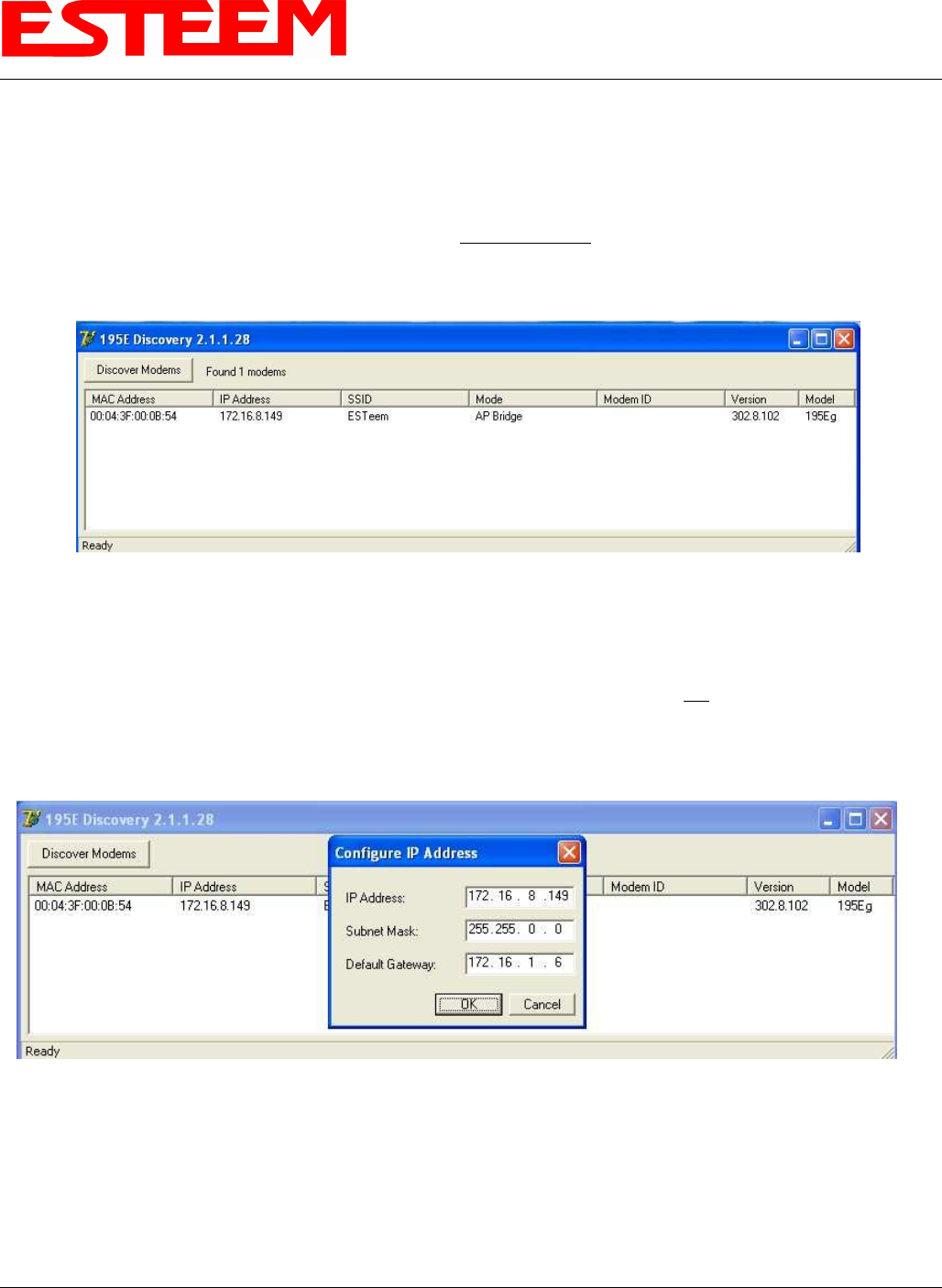
work. Open the ESTeem Discovery Program and press the Discover Modems button. The Model 195Eg will be displayed in
the program by the Ethernet MAC address and Current IP Address (Figure 3).
Note: The SSID, Mode of Operation and Modem ID will be adjusted through the web configuration manager..
5. Double-click on the 195Eg you want to program and the Configure IP Address window will be displayed (Figure 4). Enter an
IP address and Subnet Mask for the 195Eg that matches your network subnet and press the OK button to save this to the
ESTeem. You will receive notification that the Configuration was Successful and the 195Eg will reboot. Proceed to ESTeem
Setup in Chapter 4.
Figure 3: Discovery Program Main Page
Figure 4: Change IP Address Window
APPENDIX G
UTILITIES & FEATURES
Revised: 21 Mar 08 APX G-3 EST P/N AA107G
Firmware Updates
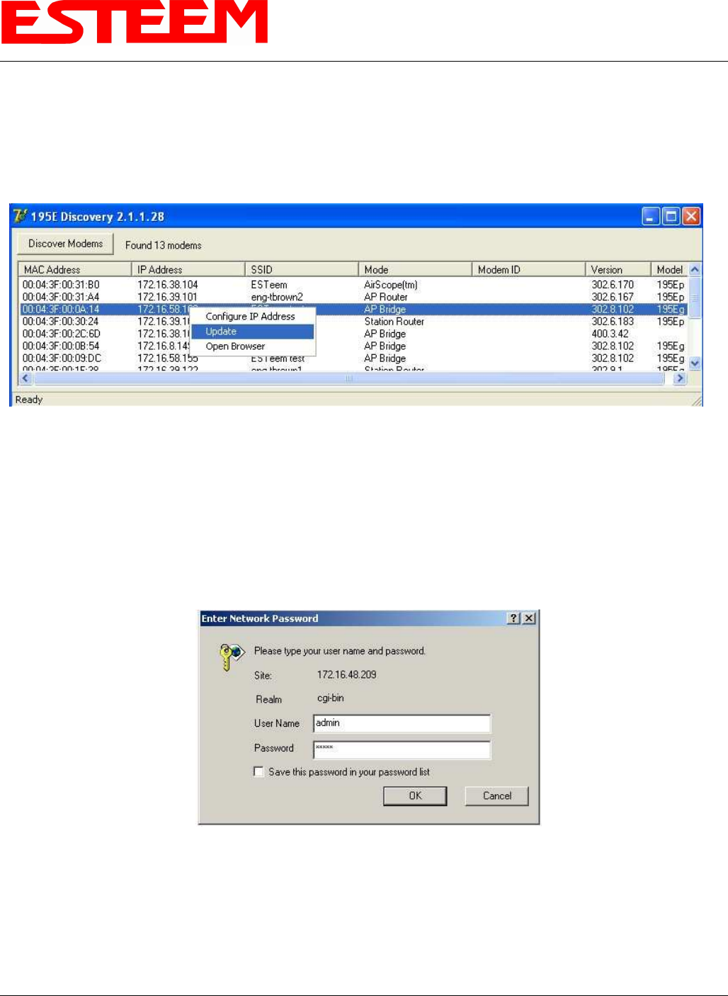
To update firmware on any ESTeem Model 195 that is shown on the Discovery program, “right-mouse” click on the 195’s MAC
address and select Update from the menu (Figure 5). Once you locate the update file, select the Open button and the 195 will
update, validate and then reboot with the updated operating system.
Opening Web Browser
To quickly open a web browser page to the IP address programmed in the 195 modem, “right-mouse” click on the 195’s MAC
address and select Open Browser from the menu (Figure 5). If your computer is configured for the same IP subnet at the ESTeem
195 wireless modem, you will be asked to sign in with the Username and Password (Figure 6) and you can begin programming the
Model 195 for your application.
Figure 5: Discovery Features Menu
Figure 6: ESTeem Web Page Log-on Screen
APPENDIX G
UTILITIES & FEATURES
Revised: 21 Mar 08 APX G-4 EST P/N AA107G
ETHERSTATION STATUS PROGRAM
When configured for EtherStation mode, the Web Configuration Manger is turned off. To gather information from the 195Eg on
Access Point, link status and received signal strength you will need to install the ESTeem 195E Status Utility. The EtherStation
Status Utility version 2.0.0.0 or greater provides a new feature where it will automatically program the connected ESTeem 195Eg
to match up with the computer running the software. This software requires that the ESTeem 195Eg has software version
302.8.102 or greater installed for this feature to function.
This software program is found on the AA109 Resources Disk or available from the ESTeem web site. To install the utility, please
complete the following:
Installation
The ESTeem Discovery Utility will allow you to configure the IP address on the Model 195Eg to match your network. Install the
Discovery Utility on your computer by inserting the Resource Disk in your CD drive.
Note: The ESTeem Resource Disk is stand-alone copy of the ESTeem Web site (Figure 1). Navigation of the Resource Disk is as
simple as using your web browser. All technical documentation, User’s Manuals and the ESTeem Utility Program is available on
the disk.
1. Place the ESTeem Utility CD in your CD-ROM drive. The CD will auto load the ESTeem main page
Note: If the page does not auto load, open your web browser and set your address line to D:\index.html (Where D: is the
drive letter for your CD-ROM drive).
2. From the Main Page select ESTeem Utilities and click on EtherStation Status Utility
Note: This program is saved in a compressed file format. Microsoft Windows XP® will open the file directly, but other
operating systems will require a common compression program such as WinZip available for download at
http://www.winzip.com
3. Double click on the 195EStatusSetup.exe file listed in the window to install the program.
4. Connect the Model 195Eg to your computer either direct
to the Ethernet card or through a HUB/Switch using a
CAT-5e Ethernet cable. The Ethernet port on the 195Eg
supports Auto-Negotiation so either a patch cable or
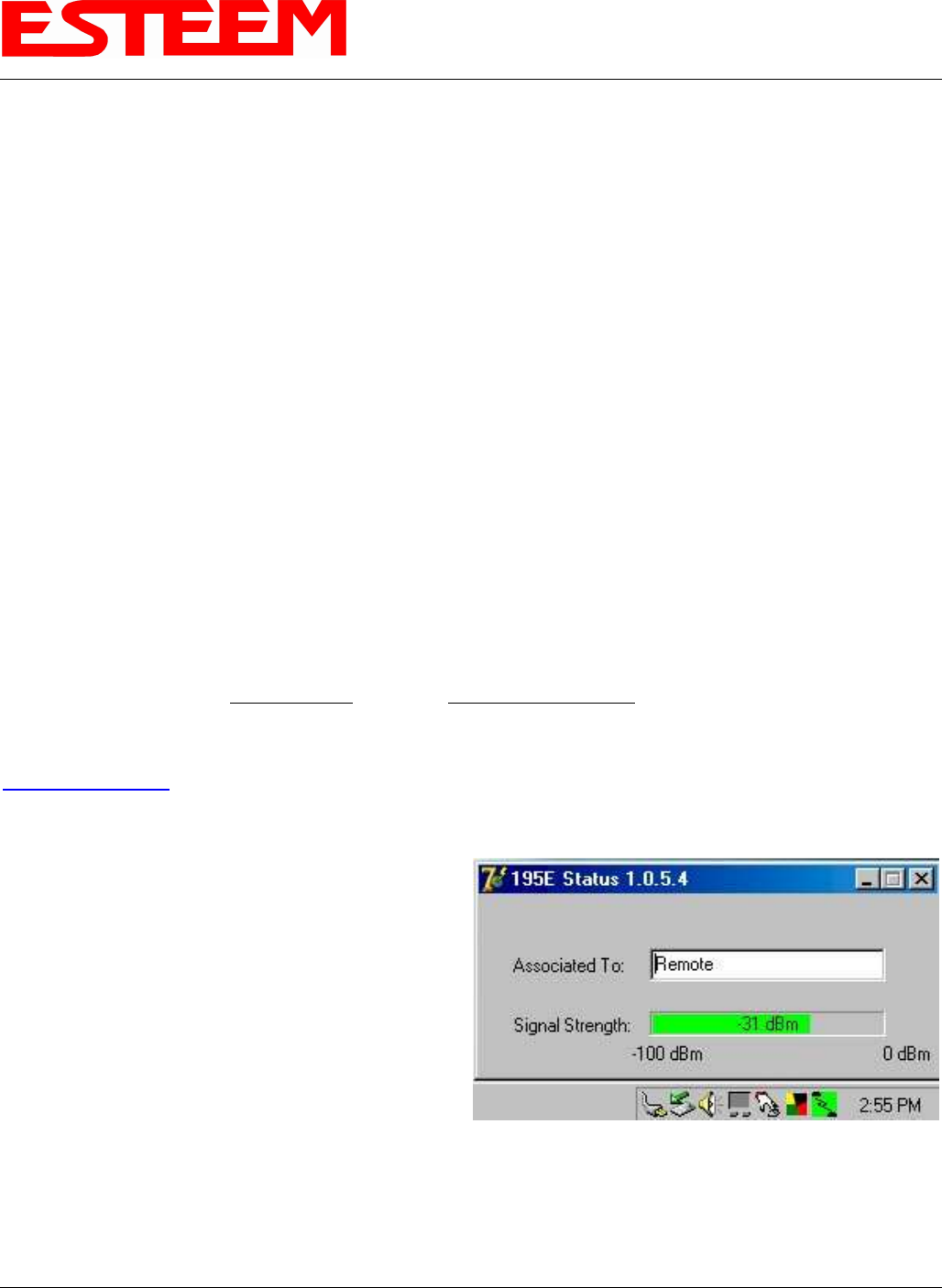
crossover cable will work. Open the ESTeem Status
Program and a status icons will appear in your system tray
(Figure 9). When the status menu is opened from the
system tray, the status window will be displayed (Figure 7)
to show the Access Point MAC address and signal
strength. The tray icon and Signal Strength bar will
display the colors from Green, Yellow to Red on
progressively poorer signal or will show Grey if roaming.
Note: This Utility will only operate with an ESTeem Model 195Eg in EtherStation mode.
Figure 7: EtherStation Status Program
APPENDIX G
UTILITIES & FEATURES
Revised: 21 Mar 08 APX G-5 EST P/N AA107G
SETTING LOCAL TIME
The ESTeem Model 195Eg will be shipped from the factory with the internal real-time clock set to Pacific Time. To change the
clock settings to the local time for accurate log file entries:
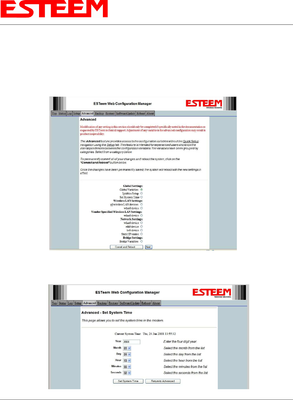
1. Select Advanced from the top Menu then Wireless LAN Settings>wlan0 device and press the Next button (Figure 8).
2. Select Global Settings>Set System Time from the menu and press the Next button to continue.
3. Select the correct date and time from the drop-down menus (Figure 9) and press the Set System Time button to save the
time to the real time clock.
Figure 8: Advanced Features Screen
Figure 9: Advanced Features Screen
APPENDIX G
UTILITIES & FEATURES
Revised: 21 Mar 08 APX G-6 EST P/N AA107G
CONFIGURING TIME SERVER
Enabling NTP time synchronization services on the ESTeem 195Eg will allow to use time services from upstream services to keep
the time on the system accurate.
To allow time synchronization, the Model 195Eg must be configured with the NTP Daemon enabled and the appropriate IP address
of the upstream network NTP server.
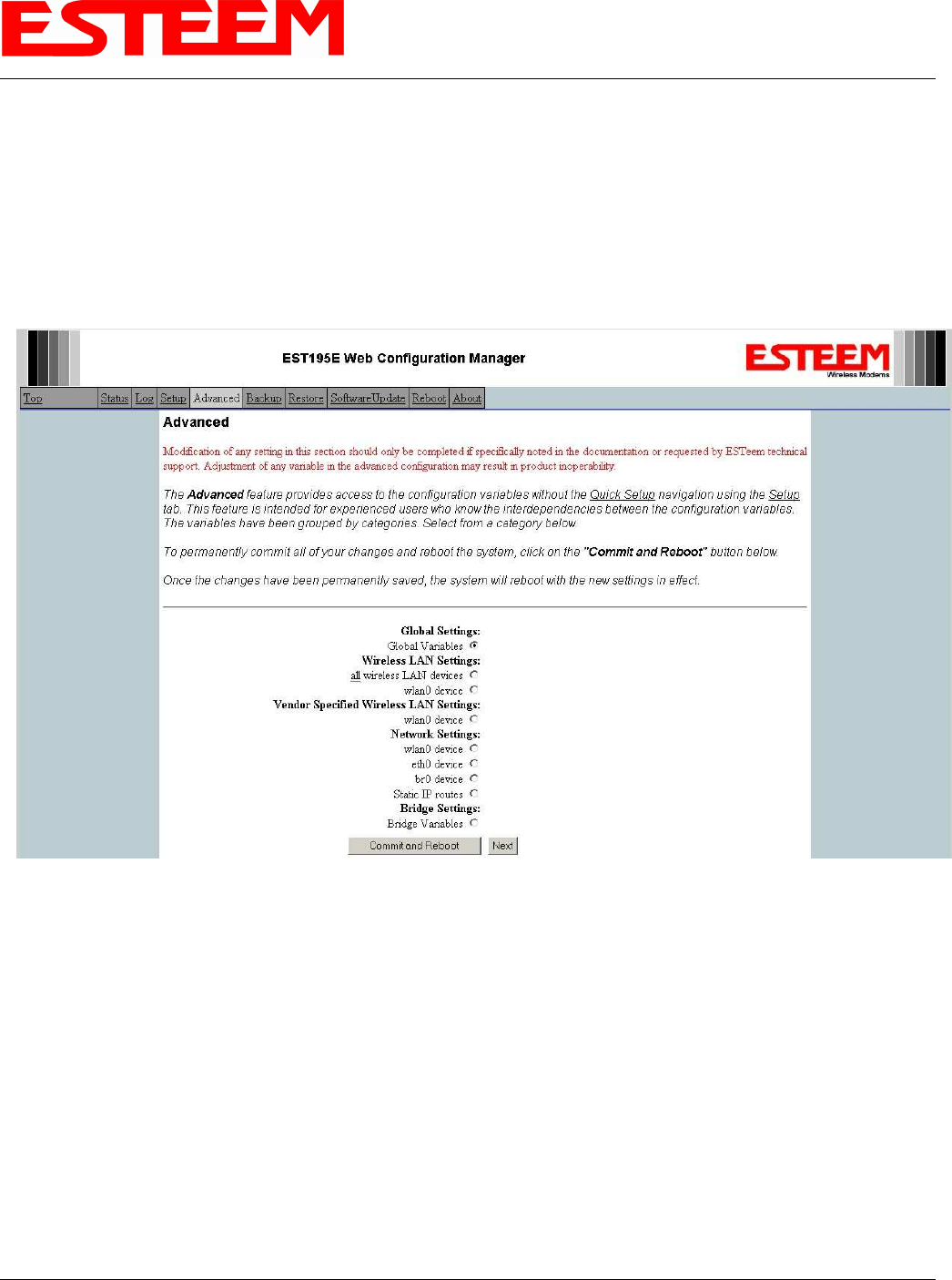
1. Select Advanced from the menu items and Global Variables (Figure 10).
Figure 10: Advanced Settings Menu
APPENDIX G
UTILITIES & FEATURES
Revised: 21 Mar 08 APX G-7 EST P/N AA107G
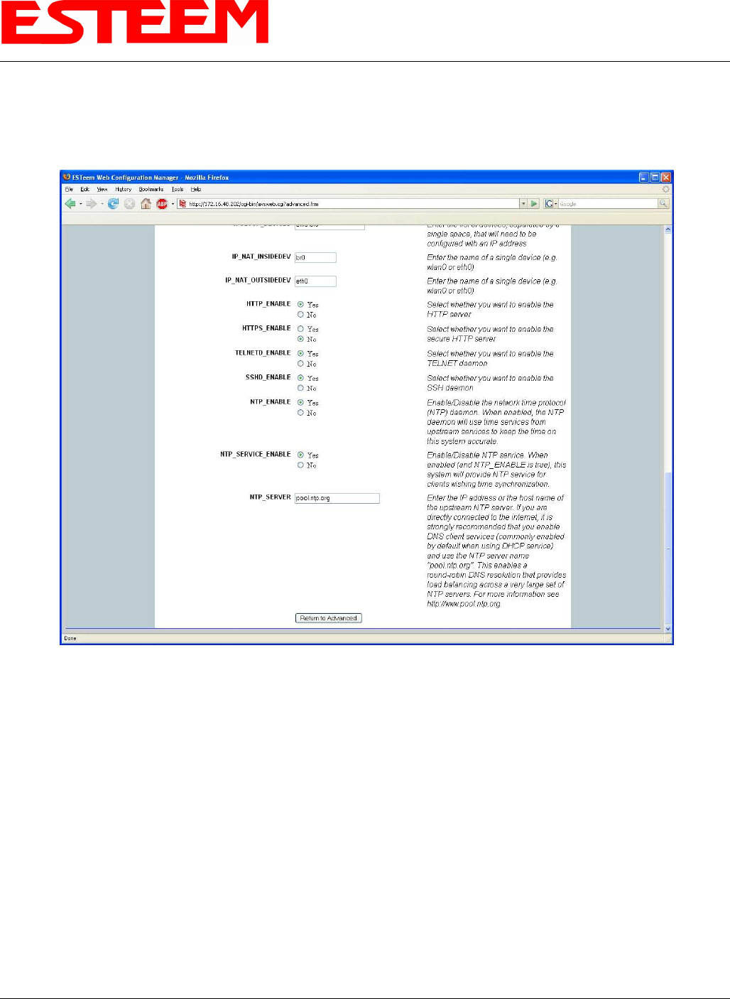
2. Press the next button and Figure 11 will be displayed. At the bottom of the page are the NTP server configurations.
3. The NTP daemon is enabled by selecting YES for NTP ENABLE (Figure 11). When enabled, the NTP daemon will use
time services from upstream services to keep the time on this system accurate.
4. Next, the NTP SERVICE ENABLE should be configured to “YES,” if you want to allow the system to provide NTP
service for clients wishing time synchronization (Figure 11).
5. The final step in configuring NTP services is to enter the IP address or the host name of the upstream NTP server.
Figure 11: NTP Settings
APPENDIX G
UTILITIES & FEATURES
Revised: 21 Mar 08 APX G-8 EST P/N AA107G
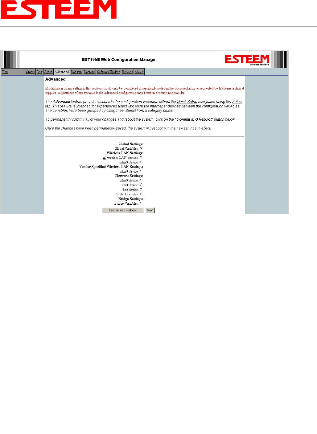
6. Once configuration is complete, press the “Return to Advanced” button.
7. To complete the configuration, select “Commit and Reboot.” The ESTeem 195Eg will now commit the configuration
changes and reboot. (Figure 12)
Figure 12: Advanced Settings Menu
APPENDIX H
QUICK START GUIDE
Revised: 21 Mar 08 APX H-1 EST P/N AA107G
Before You Begin
• The ESTeem Model 195Eg wireless Ethernet radio modem is compatible with many different applications. The most
common application is to bridge two or more Ethernet devices or networks. This guide will demonstrate the basic
configuration and testing of a pair of 195Eg’s. For a more detailed information, please see the ESTeem Model 195Eg User’s
Manual.
• This guide assumes you have a working knowledge of Ethernet networking, TCP/IP protocol and how to identify and set the
TCP/IP address on your computer.
• The 195Eg can be configured using any current web browser software such as Internet Explorer, Netscape or Mozilla.
• The following procedure will provide an initial communication link between two or more Model 195’s for testing purposes.
All the example commands listed in this guide can be adjusted to fit your communication network. Please consult the
ESTeem Model 195Eg User’s Manual for more details.
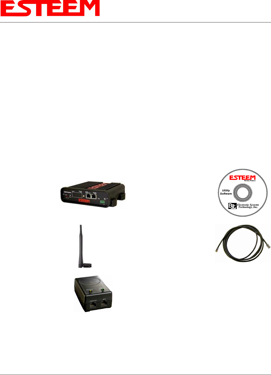
Unpack Contents
Each node in your ESTeem Model 195Eg’s network may have different hardware components based upon the final installation
location (i.e Outdoor, Indoor, Point-to-point or Muti-Point). Antenna types, cable lengths, power supplies may be different, but
the following items will be required for basic setup:
Model 195Eg
AA109 Resource Disk
Antenna
(AA01S Displayed)
(2) Ethernet Cables
Power Supply
(AA175 Displayed)
Note: Your accessory model numbers may vary from the above, but you will need to locate each of above items to continue
configuration.
APPENDIX H
QUICK START GUIDE
Revised: 21 Mar 08 APX H-2 EST P/N AA107G
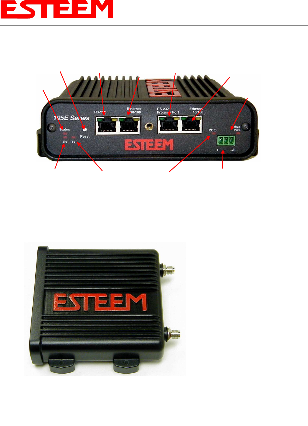
Front Panel Overview
(RS-232 Data Port and Second Ethernet Port Optional)
12 VDC Input
(Auxiliary
Connector )
Reset Switch RS-232
Configuration RJ-45 10/100BaseT
Ethernet Port
Transmit
LED
Receive
LED
Status
LED
Power over
Ethernet LED
Aux Power
LED
RS-232
Data Port
Second
Ethernet
Port
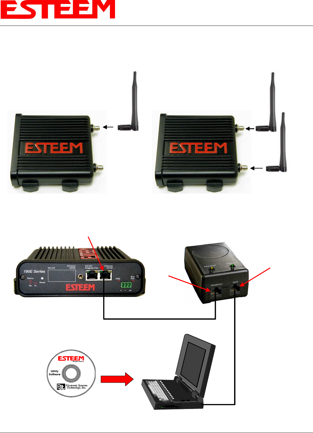
Antenna Overview
Antenna Connectors
(TNC Female-RP)
Antenna Port A
(Single Receive Antenna)
Antenna Port B
(Dual Receive Antennas)
APPENDIX H
QUICK START GUIDE
Revised: 21 Mar 08 APX H-3 EST P/N AA107G
Begin Programming
1. Assemble the ESTeem Model 195Eg using the following:
Power and Data Connection
PC with Web
Browser Software
RJ-45 10/100BaseT
Ethernet Port
10/100BaseT
Ethernet Cable
(Patch or Cross Over)
AA175 PoE
Power Supply
LAN In
10/100BaseT
Ethernet Cable
(Patch or Cross Over)
PWR
Data Out
AA109
Resource
Disk
Antenna Connections
Leave
Open
Single Antenna
Configuration Dual Antenna
Configuration

APPENDIX H
QUICK START GUIDE
Revised: 21 Mar 08 APX H-4 EST P/N AA107G
2. The Model 195Eg will link to other Model 195Eg’s on the network via the WLAN Media Access Control (MAC) address
found on the bottom of the case. This MAC address is six hexadecimal digits separated by colons and is configured at the
factory. Every MAC address in the world is unique and can not be changed. Complete the following chart to aid in your
configuration:
Name Serial Number IP Address Ethernet MAC WLAN MAC
Example Modem 1 E-14001
172.16.8.101 00:04:3f:00:01:01 00:04:3f:00:01:02
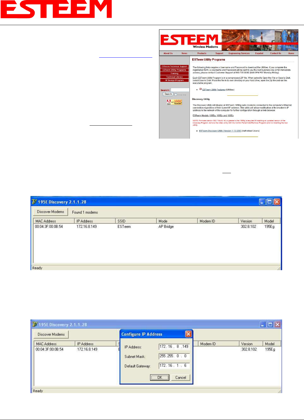
3. Configuration of the Model 195Eg is completed through the product’s internal web server. To access this configuration page,
you will need to enter the 195Eg’s IP address in your web browser. The IP address set at the factory is Class B (i.e.
172.16.x.x) address and is printed on the Quality Assurance sheet sent with each 195Eg. If the factory default address
matches your network configuration, please proceed to Using Setup, otherwise continue to step 4.
4. Install the ESTeem Discovery Utility. The ESTeem Discovery Utility will allow you to configure the IP address on the
Model 195Eg to match your network. Install the Discovery Utility on your computer by inserting the Resource Disk in your
CD drive.
Note: The ESTeem Resource Disk is stand-alone copy of the ESTeem Web site (Figure 1). Navigation of the Resource Disk is
as simple as using your web browser. All technical documentation, User’s Manuals and the ESTeem Utility Program is
available on the disk.
Place the ESTeem Utility CD in your CD-ROM drive. The CD will auto load the ESTeem main page
Note: If the page does not auto load, open your web browser and set your address line to D:\index.html (Where D: is the
drive letter for your CD-ROM drive).
From the Support Menu select ESTeem Utilities and click on ESTeem Discovery Utility.
Figure 1 –ESTeem Resource Disk Main Page
APPENDIX H
QUICK START GUIDE
Revised: 21 Mar 08 APX H-5 EST P/N AA107G
Note: This program is saved in a compressed file format.
Microsoft Windows XP® will open the file directly, but other
operating systems will require a common compression program
such as WinZip available for download at http://www.winzip.com
Double click on the 195EdiscoverySetup.exe file listed in the
window to install the program.
5. Set IP Address on the 195Eg. Connect the Model 195Eg to
your computer either direct to the Ethernet card or through a
HUB/Switch using a CAT-5e Ethernet cable. The Ethernet
port on the 195Eg supports Auto-Negotiation so either a
patch cable or crossover cable will work. Open the ESTeem
Discovery Program and press the Discover Modems button.
The Model 195Eg will be displayed in the program by the
Ethernet MAC address and Current IP Address (Figure 3).
Note: The SSID and Mode of Operation will be adjusted
later in the configuration.
Double-click on the 195Eg you wish to program and the Configure IP Address window will be displayed (Figure 4). Enter an
IP address and Subnet Mask for the 195Eg that matches your network subnet and press the OK button to save this to the
ESTeem. You will receive notification that the Configuration was Successful and the 195Eg will reboot. Proceed to ESTeem
Setup to continue configuration.
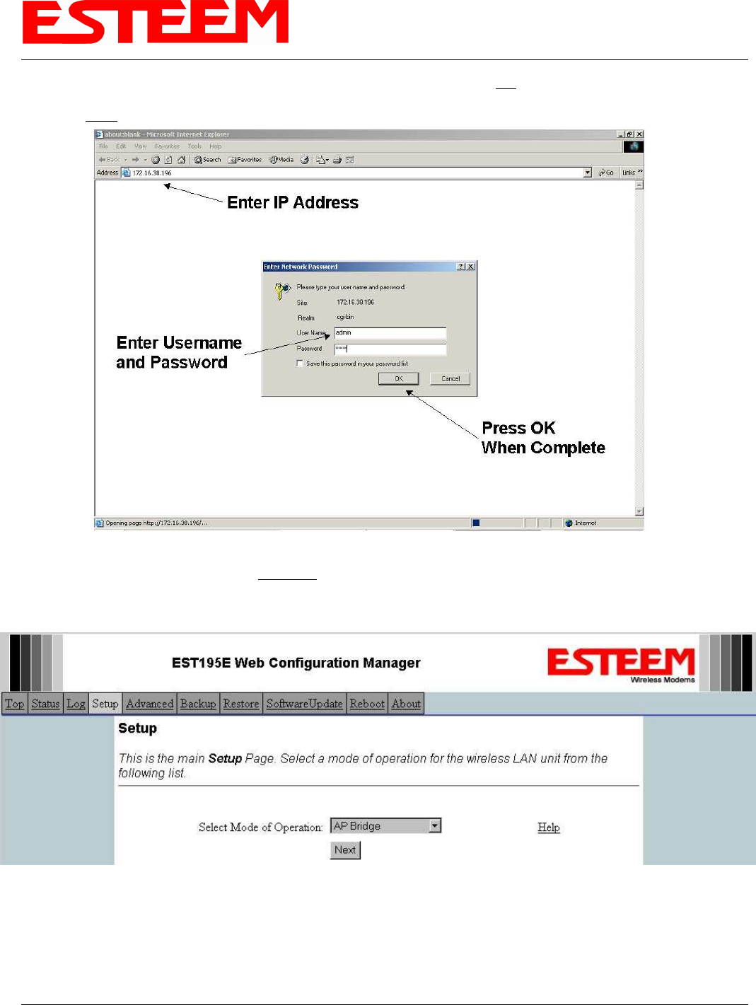
Setup Programming
You should now be ready to configure the Model 195Eg through your web browser. Open the web browser program and enter the
IP address of the ESTeem in the address line and press enter.
Figure 2- ESTeem Utility Download
Figure 3 – Discovery Program Main Page
Figure 4 – Change IP Address Window
APPENDIX H
QUICK START GUIDE
Revised: 21 Mar 08 APX H-6 EST P/N AA107G
1. When prompted, enter admin for both the username and password and press the OK button.
2. Select Setup on the top menu.
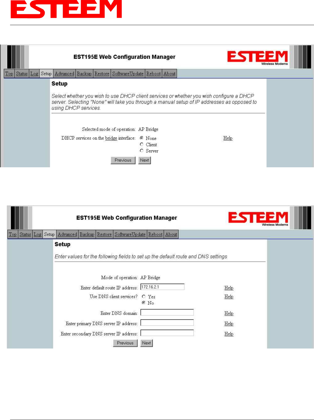
3. Press the drop-down menu and select AP Bridge and press the Next button.
Step 1 – Sign-In Screen
Step 3 – Select AP Bridge
APPENDIX H
QUICK START GUIDE
Revised: 21 Mar 08 APX H-7 EST P/N AA107G
4. Set the DHCP services to OFF and press the Next button.
5. Verify the IP address and netmask for the 195Eg (listed as bridge device) are correct press the Next button.
Step 4 – Turn DHCP Off
Step 5 – Verify IP Address
APPENDIX H
QUICK START GUIDE
Revised: 21 Mar 08 APX H-8 EST P/N AA107G
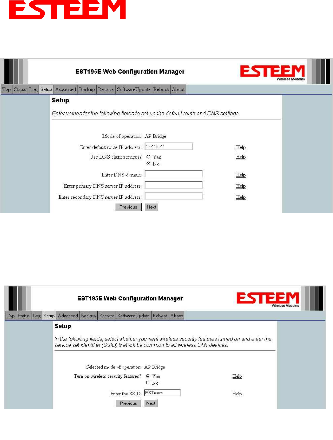
6. Enter in the Gateway address in the default route IP address block and any DNS information for the server. If this is not
know or on a network without a Gateway, leave these items at factory default.
7. All 195Eg modems in the network must be have the exact same Service Set Identification (SSID). The default SSID is
ESTeem and we will use this for demonstration. Enter the SSID as listed above and turn off the wireless security features by
selecting the NO radial. Press the Next button to continue.
Note: It is recommended that security be used in all wireless applications. This procedure will forgo the security configuration
for brevity. Please see the example applications and the security appendix for further information.
Step 6 – Enter Gateway Address
Step 7 – Enter SSID
APPENDIX H
QUICK START GUIDE
Revised: 21 Mar 08 APX H-9 EST P/N AA107G
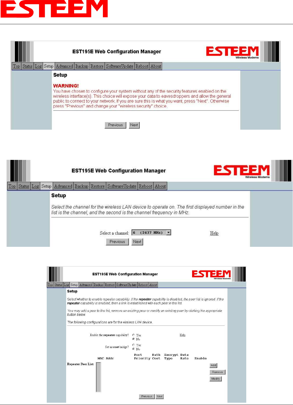
8. A warning that wireless security is not enabled will be displayed. Press the Next button to continue.
9. All Model 195Egs on the network must be on the same radio channel, representing a particular frequency. If a particular
channel has not been assigned for use, leave the 195Eg at a default value of 6 and press the Next button.
Step 8 – Security Warning Screen
Step 10 – Set Radio Channel
APPENDIX H
QUICK START GUIDE
Revised: 21 Mar 08 APX H-10 EST P/N AA107G
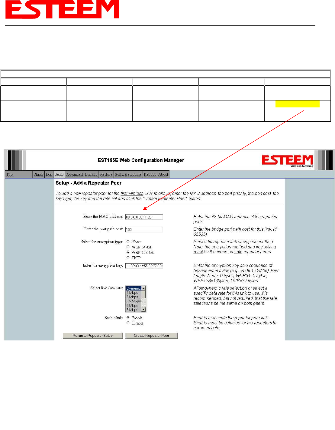
10. Configure the repeater peer list by selecting Enable the repeater capability radial to YES (Above). Press the Add button to the
right of the repeater peer table and, using the chart created in the Begin Programming section of this guide, enter the
Wireless MAC (WLAN MAC) address of the opposite 195Eg (the 195Eg this unit you are programming will communicate
with) in the Peer 1 – MAC Addr field (right). Leave the Priority and Cost settings at the default values and change the Enable
Link radial to Enable and press the Create Repeater Peer button. Press the Next button.
11. Press the Commit Changes button and the modem will save all the changes made and reboot. The reboot time is
approximately 1 minute to be ready for operation.
12. Complete all steps in this Setup Programming section for the other Model 195Eg’s you will be testing before moving on the
Testing Communication section.
Example Addresses
Name Serial Number IP Address Ethernet MAC WLAN MAC
195Eg We Are
Programming E-14096
172.16.48.189 00:04:3f:00:01:01 00:04:3f:00:01:02
Opposite 195Eg We
Will Create Wireless
Link
E-14034
172.16.38.114 00:04:3F:00:0B:00
00:04:3F:00:11:02
Step 10 – Configure Peer Table
APPENDIX H
QUICK START GUIDE
Revised: 21 Mar 08 APX H-11 EST P/N AA107G
Testing Communication Link
After you have configured at least two of the Model 195Eg wireless Ethernet modems for operation, you can verify
communication with each the following steps:
Status Light – The quickest source of link status is to view
the Status Light on the face of the 195Eg. If the Status light
is solid, the Model 195Eg has a connection to another Model
195Eg listed in the Peer Table.
Status Screen/Peer Table – To view further information on
the status of the communication link (such as connection
speed, signal strength and last update time) you can open the
Status Screen from the Web Interface. After press the Status
tab at the top of the screen the Status: Summary will be
displayed showing the status of all ports and memory in the
195Eg. Under the Wireless Status heading click on the View Peer Table (Figure 5). The Peer Table will list all other 802.11b or
802.11g wireless activity seen by the 195Eg and how it is classified.
Find the opposite 195Eg in the Repeater Peers list and information such as signal strength (in dBm) and time/speed of last data
packet will be displayed.
Note: The data rate displayed is not necessarily indicative of the RF data rate between the ESTeems. The rate show in the
Repeater Peer table will be the last RF packet, which could consist of either data, repeater beacon or network probes. For a
detailed analysis on the data rate, please consult the ESTeem User’s manual.
Status LED
Solid Red on Link
Opposite Modem’s Wireless MAC
Receive Signal Strength (dBm)
Last Packet Received
Peer Modem ID
Other Access Points
Figure 5 – Repeater Peer Table

APPENDIX H
QUICK START GUIDE
Revised: 21 Mar 08 APX H-12 EST P/N AA107G
Ping Testing – The easiest method for testing the efficiency of data flow between the ESTeems is to conduct a Ping test to the
opposite modem’s IP address. This will test all links in the Ethernet bridge.
Technical Support
User’s Manual and Technical Documentation
http://www.esteem.com
E-Mail Support
Support@esteem.com
Phone Support (8AM to 5PM PST Monday-Friday)
509-735-9092