Flir BelgiumBA DP4KW Light Marine Navigational Radar User Manual E Series Networked Display Ref Manual Part 4
Raymarine UK Ltd. Light Marine Navigational Radar E Series Networked Display Ref Manual Part 4
Contents
E Series Guide Part 4
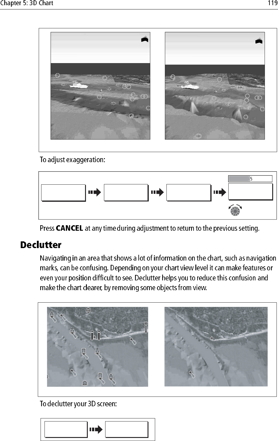
Exaggeration factor x1 Exaggeration factor x50
D8253_2
D8238_2
3D VIEW
OPTIONS...
PRESENTATION… ADJUST
EXAGGERATION
ADJUST
EXAGGERATION
2
Adjust factor
as required
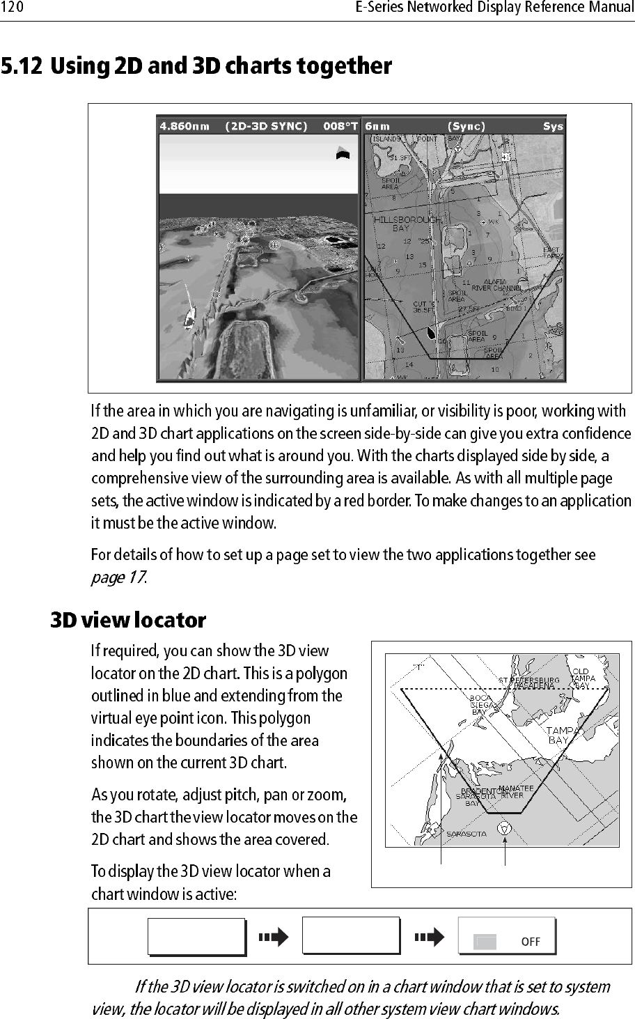
Declutter ONDeclutter OFF
D8254_1
PRESENTATION DECLUTTER
ON OFF
D8241_1
Note:
D8255_1
D8256_1
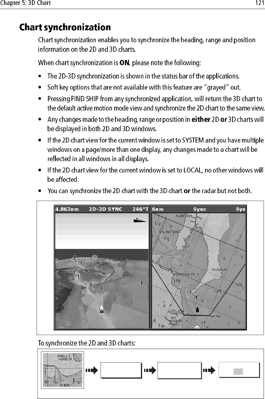
View locator Eye point icon
PRESENTATION
CHART LAYERS...
D8243_1
3D LOCATOR
O
N
D8257_1
CHART MODE AND
ORIENTATION...
D8244_1
PRESENTATION
Chart application active
CHART SYNC
RDR 3D OFF
D8259_2
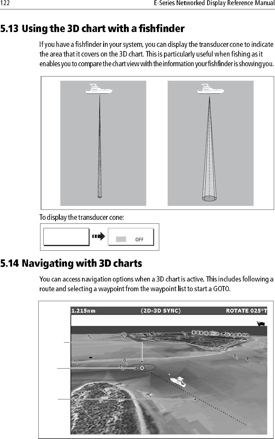
50 kHz
200 kHz
D8237_1
TRANS CONE
PRESENTATION…
O
N
D8258_2
Active
waypoint
Course
of route
Waypoint
arrival
circle
Note:
Note:
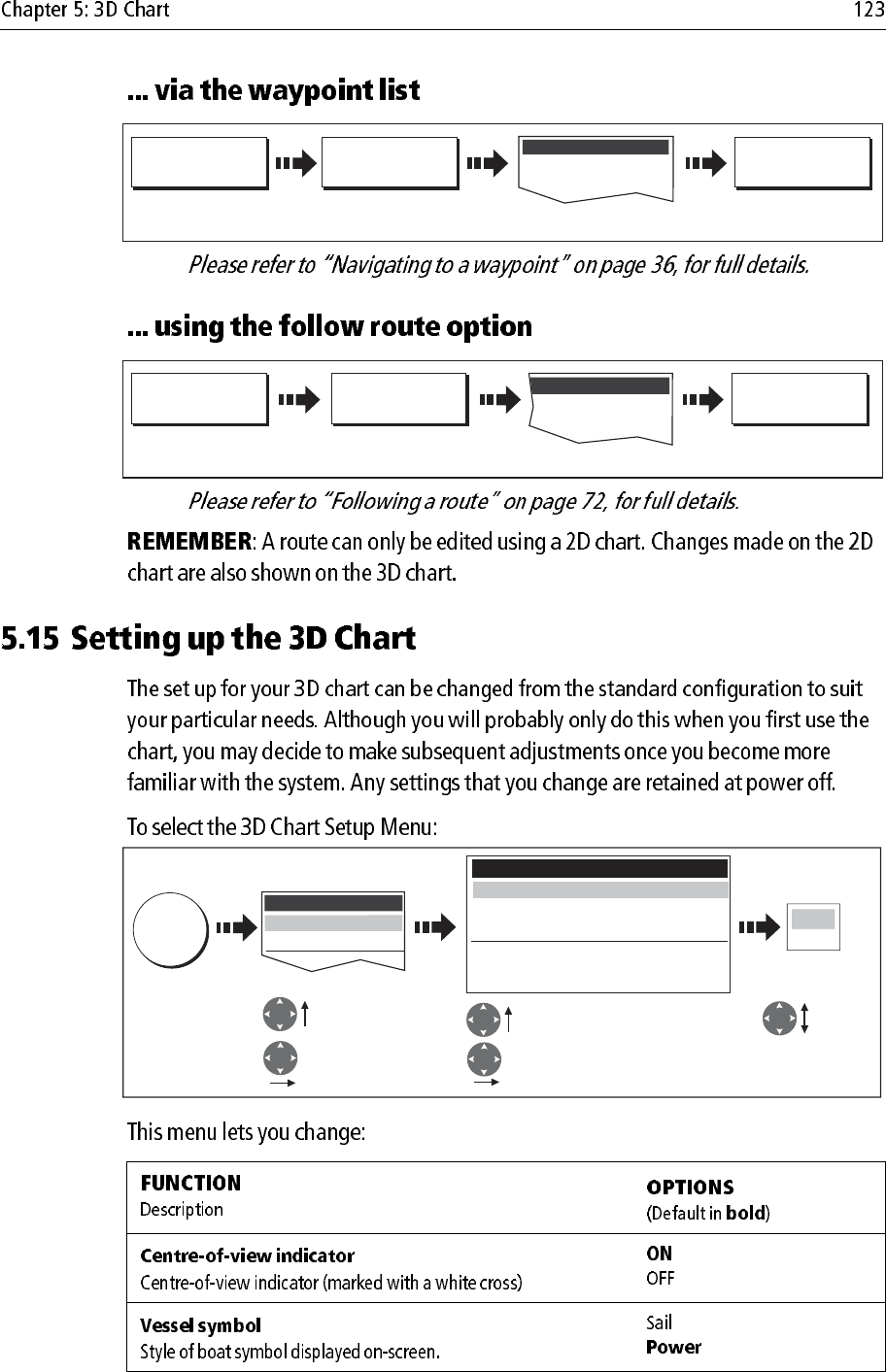
Waypoint List
D8245-1
GOTO WAYPOINT
OPTIONS ... GOTO WAYPOINT
GOTO...
Select required waypoint
D8847-1
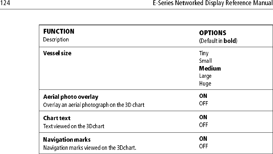
FOLLOW ROUTE
OPTIONS ... FOLLOW ROUTE
GOTO...
Route List
Select required route
D8242-1
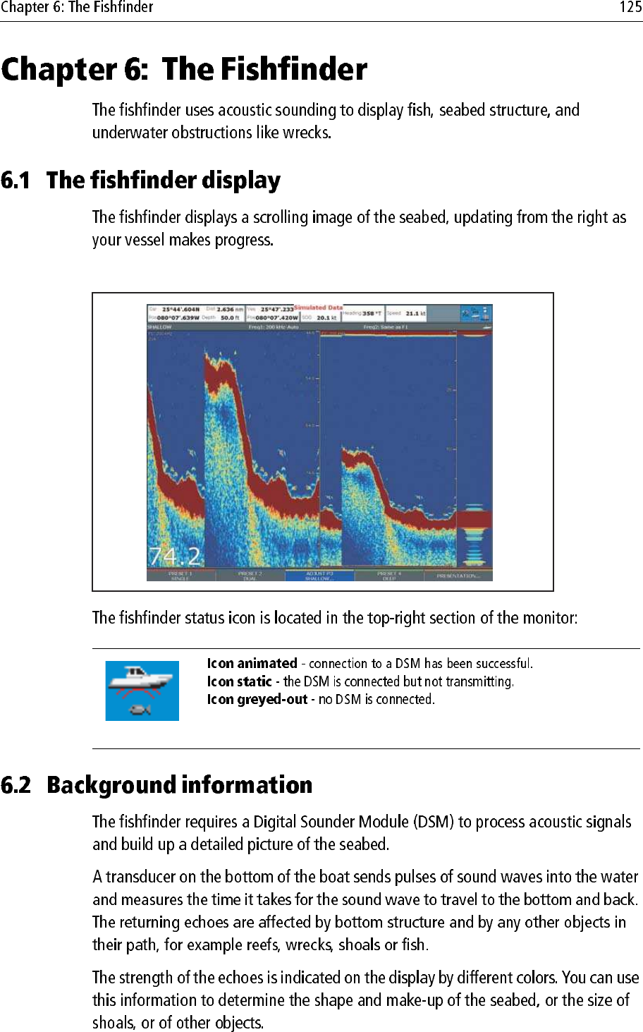
Highlight 3D Chart
Setup menu Highlight required function
Change
status as
required
Enter 3D Chart
Setup menu Enter function
MENU
Setup
3D Chart Setup...
Centre-of-View Indicator
Vessel Symbol
Aerial Photo Overlay
Chart Text
Nav. Marks
3D Chart Setup Menu
ON
Power
ON
ON
ON
OFF
ON
e.g.
D10560-1
D9534_1
(animated icon)
D6855-2
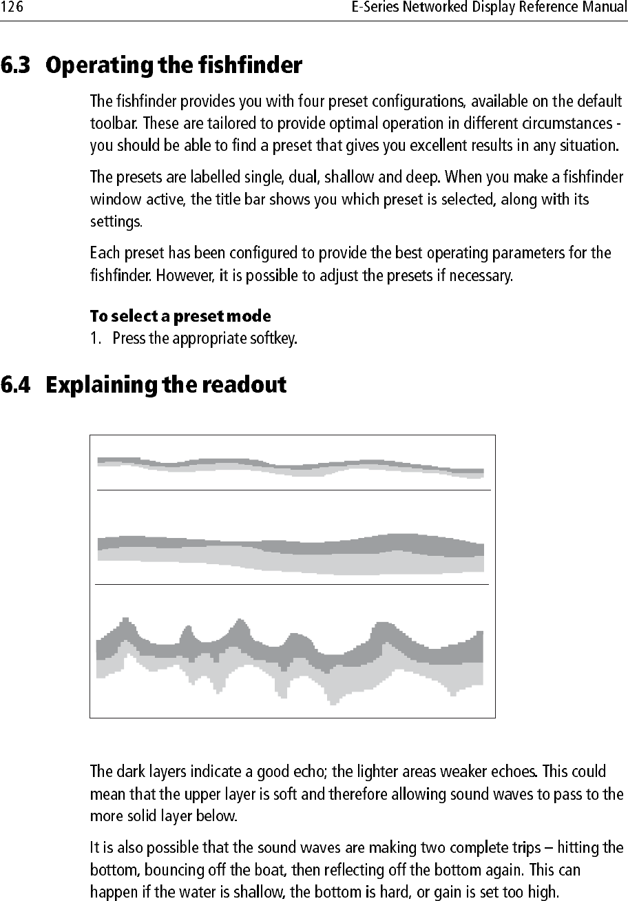
A hard bottom (sand) produces a thin line
A soft bottom (mud or seaweed cover) produces a wide line.
The dark layer indicates a strong signal.
A rocky or uneven bottom or a wreck produces an irregular
image with peaks and troughs
F1 F2
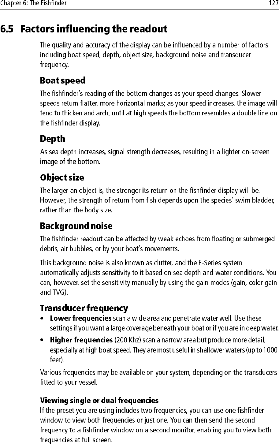
OK
FULL SPLIT ZOOM
ZOOM
MAN ZOOM POSITION
OK
D10613_1
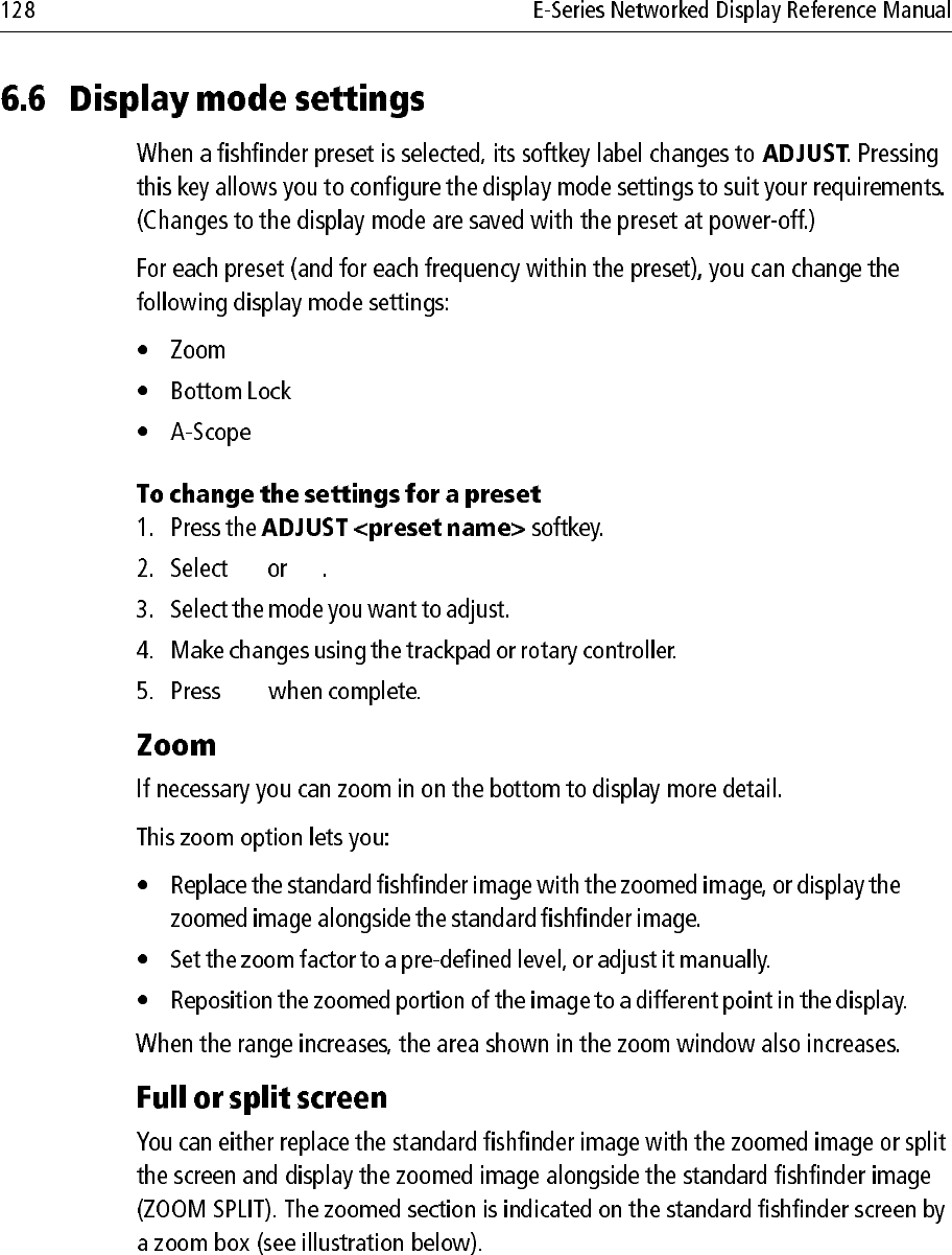
FULL SPLIT
BL
B-LOCK RANGE
50ft
BOTTOM SHIFT
14%
BOTTOM LOCK
FULL SPLIT
F1: 200 kHz
SHALLOW Freq1: 200 kHz-Auto Freq2: None
SELECT OPTION
BOTTOM LOCK
ADJUST
FREQ1 FREQ2
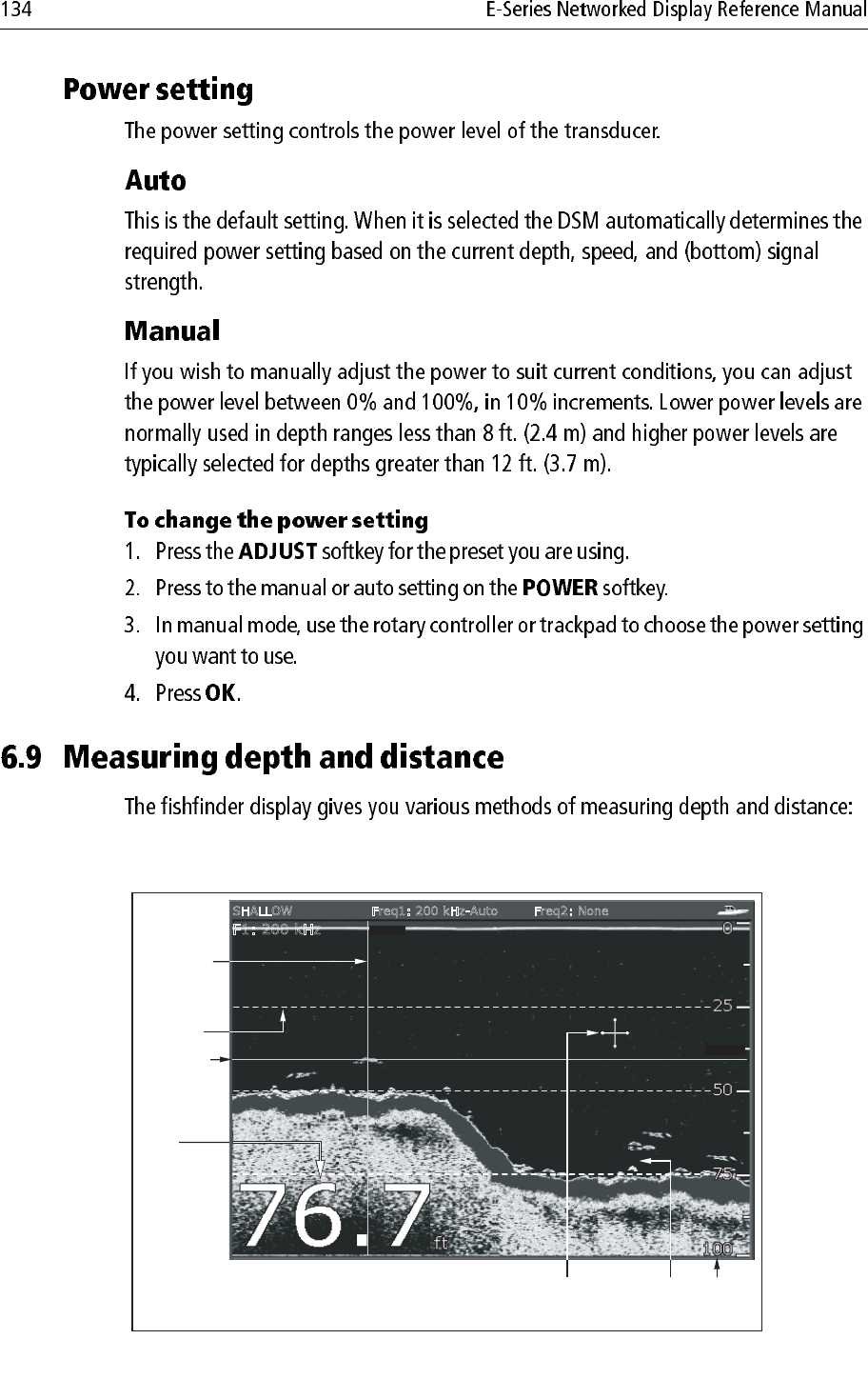
Depth from the surface
Bottom lock range
(distance from bottom)
Bottom
shift
Depth
reading
Bottom lock image Standard fishfinder image
D10412-1
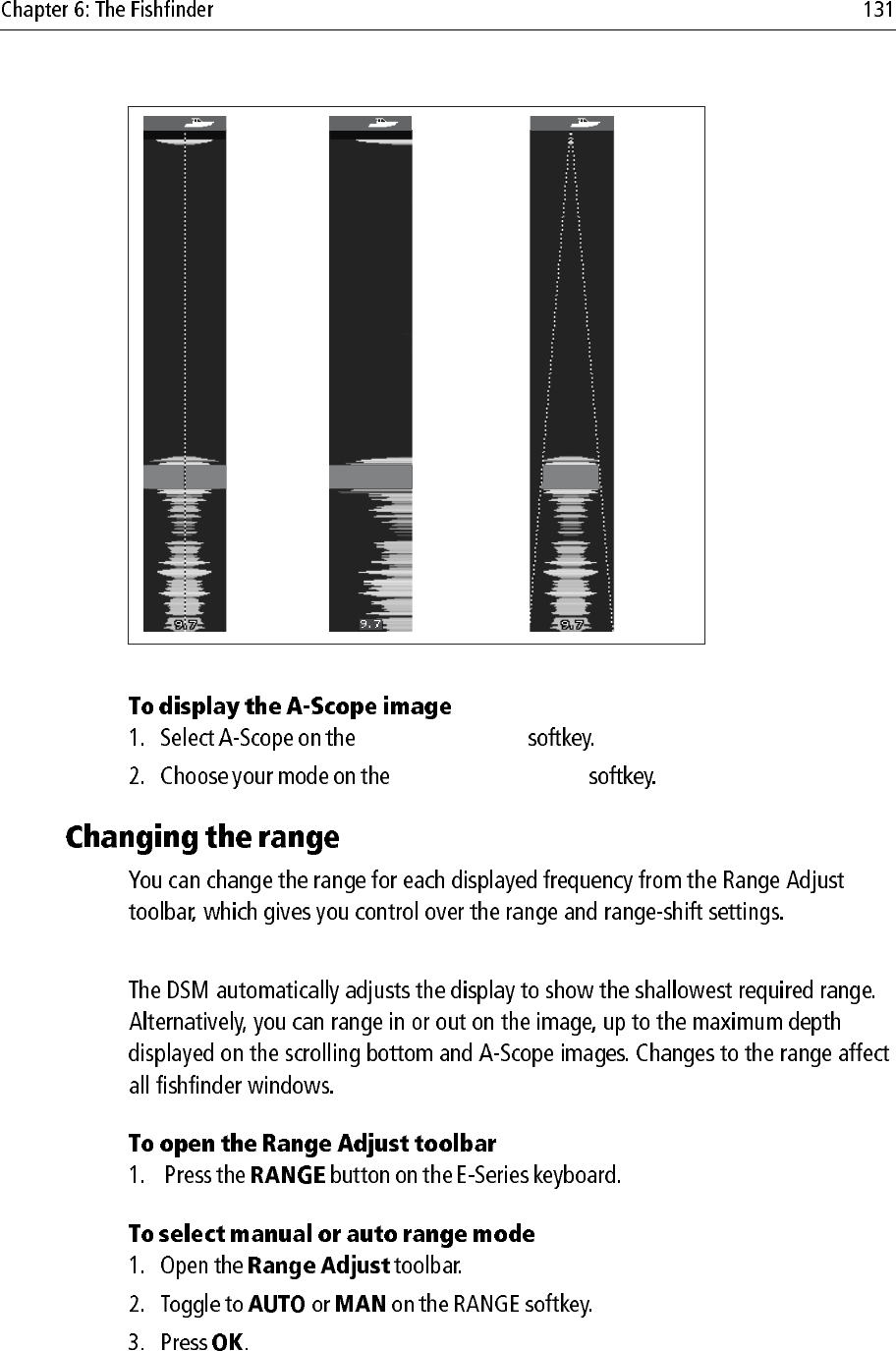
SELECT VIEW
A-SCOPE MODE
D6674-3
MODE 1
The A-scope
image is centred
in the window.
MODE 2
The left-hand side
of the Mode 1
image is expanded
to give a more
detailed view.
MODE 3
The A-scope
image angles
outward as
signal width
increases with
depth.
GAIN MODE
OK
GAIN MODE
MAN
OK
74
70
67
74
49
46
44
1768ft
42.2ft
63
74 75
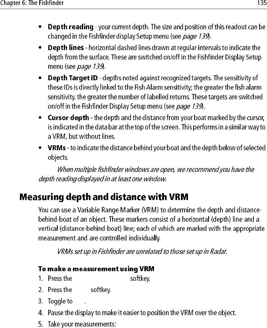
VRM 1
ON OFF
RANGE
0.787nm
DEPTH
44.7ft
F1: 200 kHz
SHALLOW Freq1: 200 kHz-Auto Freq2: None
VRM marker
indicating
depth of target
Depth
reading
Depth line
Depth
markers
Depth
target ID
Cursor
(depth indicated
in data bar)
VRM marker
indicating
distance
behind boat
D10411-1
Note:
Note:
PRESENTATION
VRM
ON
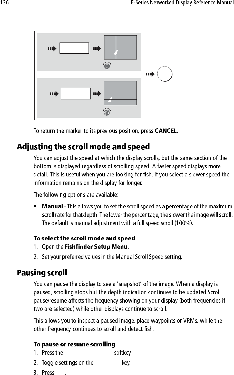
PRESENTATION
SCROLL
OK
Move range
marker over target
RANGE
49ft
Measuring distance
Measuring depth
and/or
e.g.
e.g.
Press to highlight
DEPTH
10ft
1.56nm
Move depth
marker over target
12ft
D8455_1
OK
To save
position
MENU
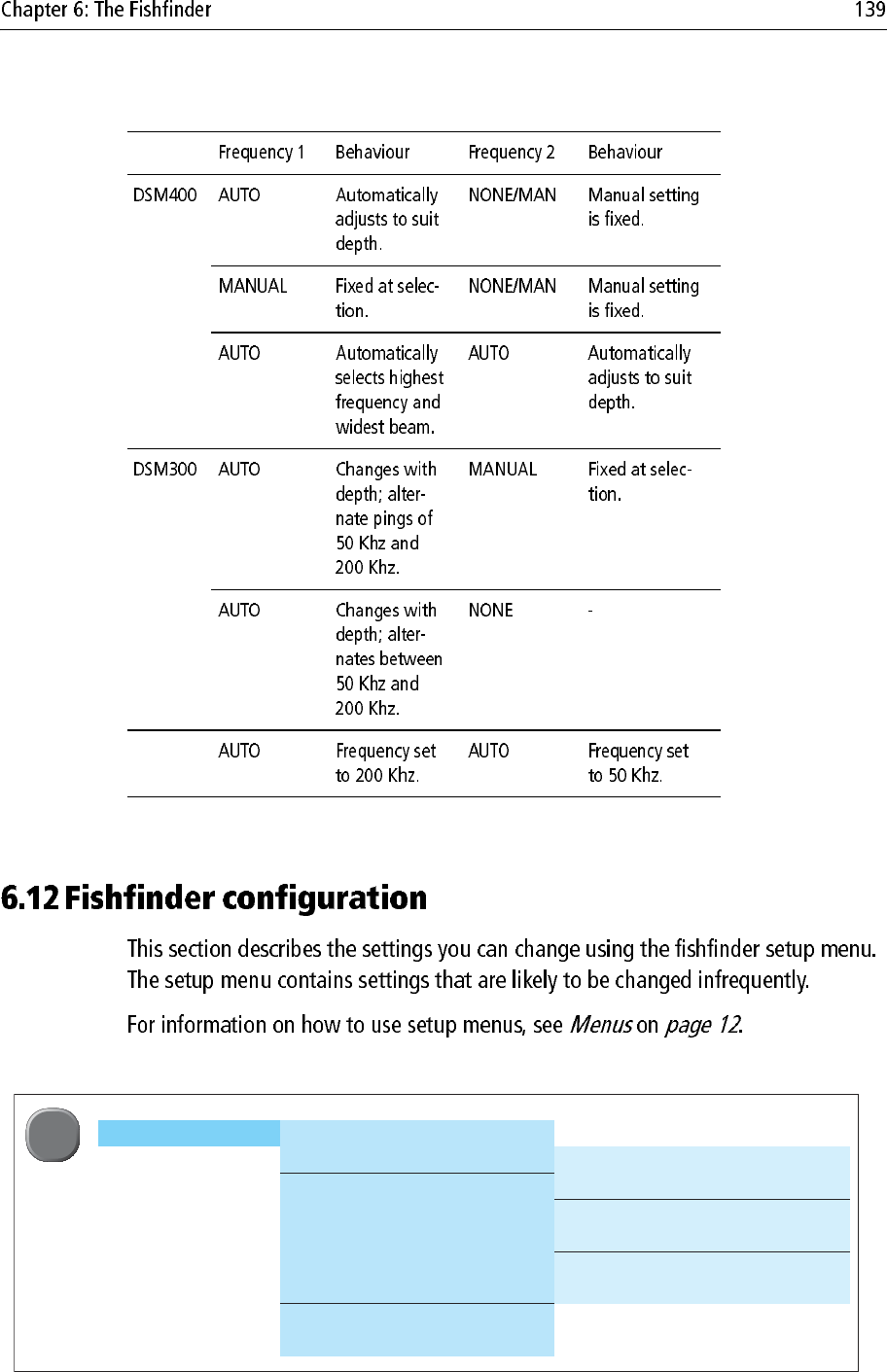
Configure Frequency Presets
Radar Setup > Select Scanner
Scanner Setup > Dual Range
Color Palette
EBL Reference Tune
Timed Transmit Sea Clutter Curve
Transmit Period Parking Offset
Standby Period Scanner Size
Bearing Alignment
Radar Advanced Setup
MENU
D10612-1
MENU
Note:
75.9
ft
100
75
200 kHz: Auto Gain: Auto High
75.9
ft
100
75
200 kHz: Auto Gain: Auto High
75.9
ft
200 kHz: Auto Gain: Auto High
75.9
ft
75
200 kHz: Auto Gain: Auto High
D6833-3
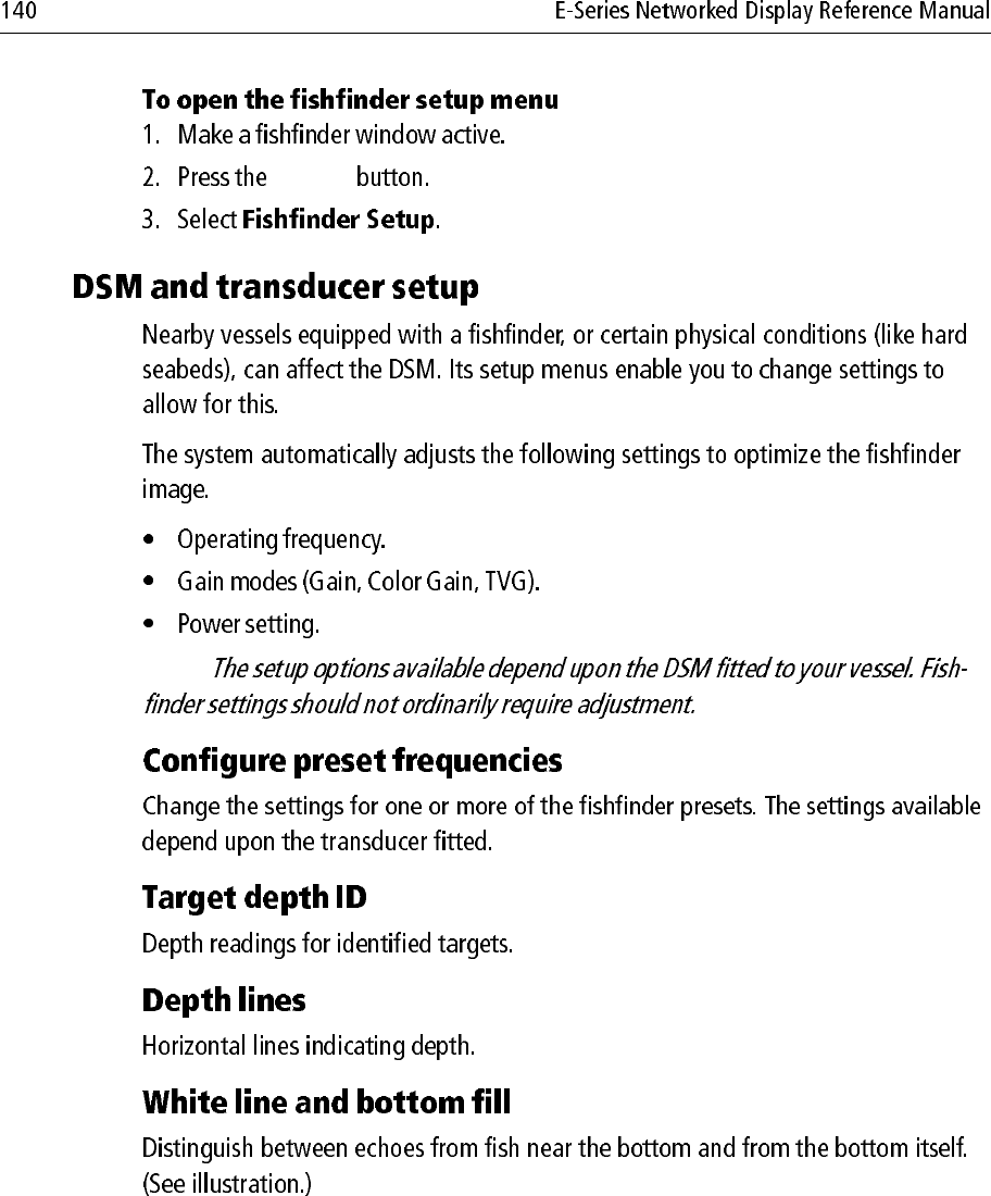
Standard fishfinder image
The standard fishfinder image displays the
bottom as a combination of features (mud,
sand, fish targets etc) with various sonar
signal strengths.
White line
When this feature is applied, a white lIne
is drawn along the bottom (as defined by
the digital depth value) and the detail
below the bottom removed.
Fish near the bottom can now be seen
more easily.
Bottom fill
When this feature is applied, the detail
below the bottom is removed and
replaced by a single contrasting color.
The bottom is now clearly defined and the
fish near the bottom can be seen more
easily.
White line and bottom fill
When both White Line and Bottom Fill
are applied, the bottom is defined by a white
line and the detail below it replaced by a
single contrasting color.
Both the bottom and fish near the bottom
are now clearly defined.
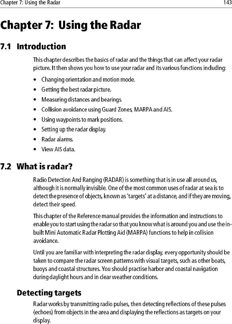
a1a2
Earth
h
H
Cliff
Radar
D1643-3
Rmax
Rmax = 2.23 ( h + H )
Rmax
h
H
maximum radar range
radar antenna height
target height
in nautical miles
in metres
in metres
Rmax = radar horizon of antenna (a1) + radar horizon of target (a2)
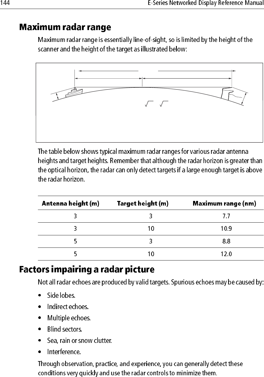
True echo Side echoes
Main lobe
Antenna
Arc
Side
lobe
Side
lobe
D1638-4
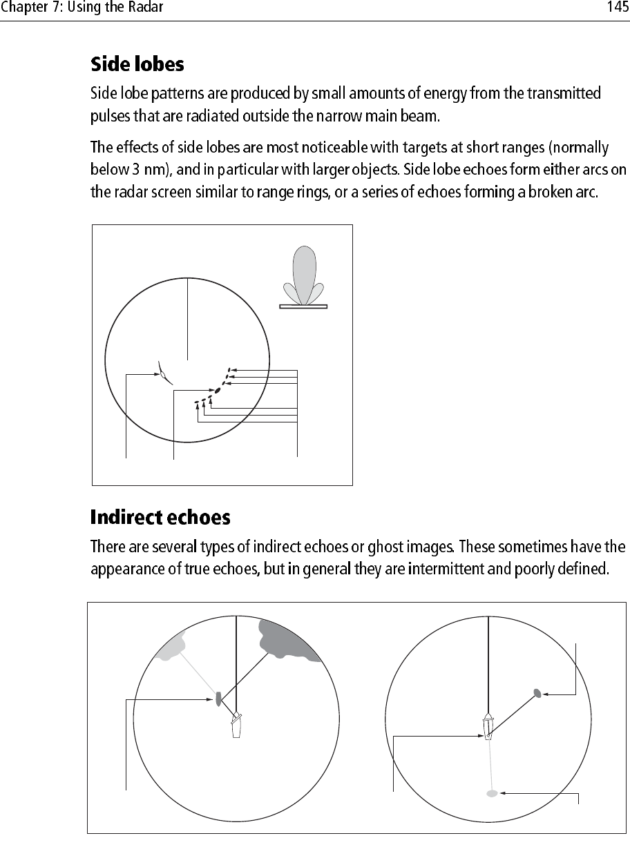
False echo
Passing
ship
True echo
D1641-4
True echo
False echo
Mast
or funnel
D1642-3
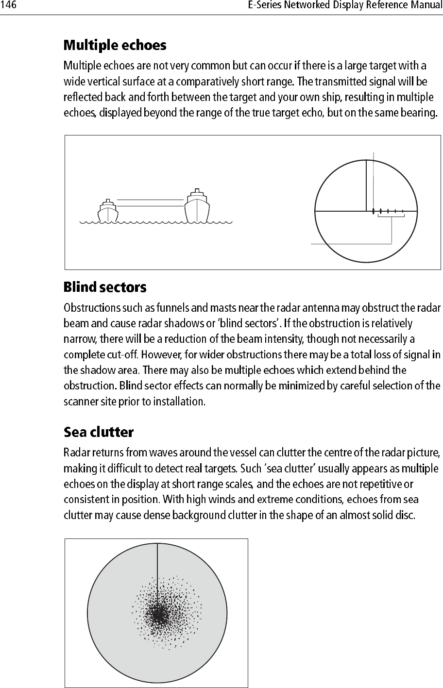
True echo
Multiple echoes
D3968-4
D3967-4
D6601-2
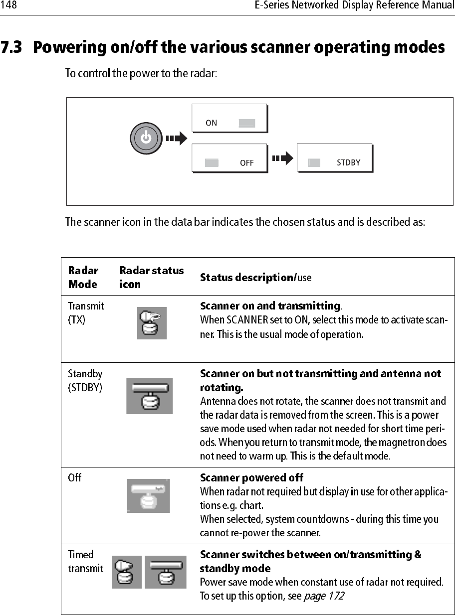
Notes: (1) When an open array antenna is fitted, the system stops the antenna in
the forward facing position when Standby mode is selected.
(2) Dual radar support will only allow one radar to be active at any one
time. You cannot set up two radar windows, each using a different
scanner.
SCANNER
RADAR
O
F
F
SCANNER
O
NTX
Select required
operating mode
Switch scanner ON
or OFF
D8397_1
D7440-1
(Rotating icon)
D6894-2
(static icon)
D7441-1
(grayed-out icon)
D7442-1
(rotating/static icon)
3nm Head-Up Relative Motion Rings ½nm
VRM/EBL... GAIN... PRESENTATION...
TARGET
TRACKING...
ENHANCE
ECHOES...
D6803-3
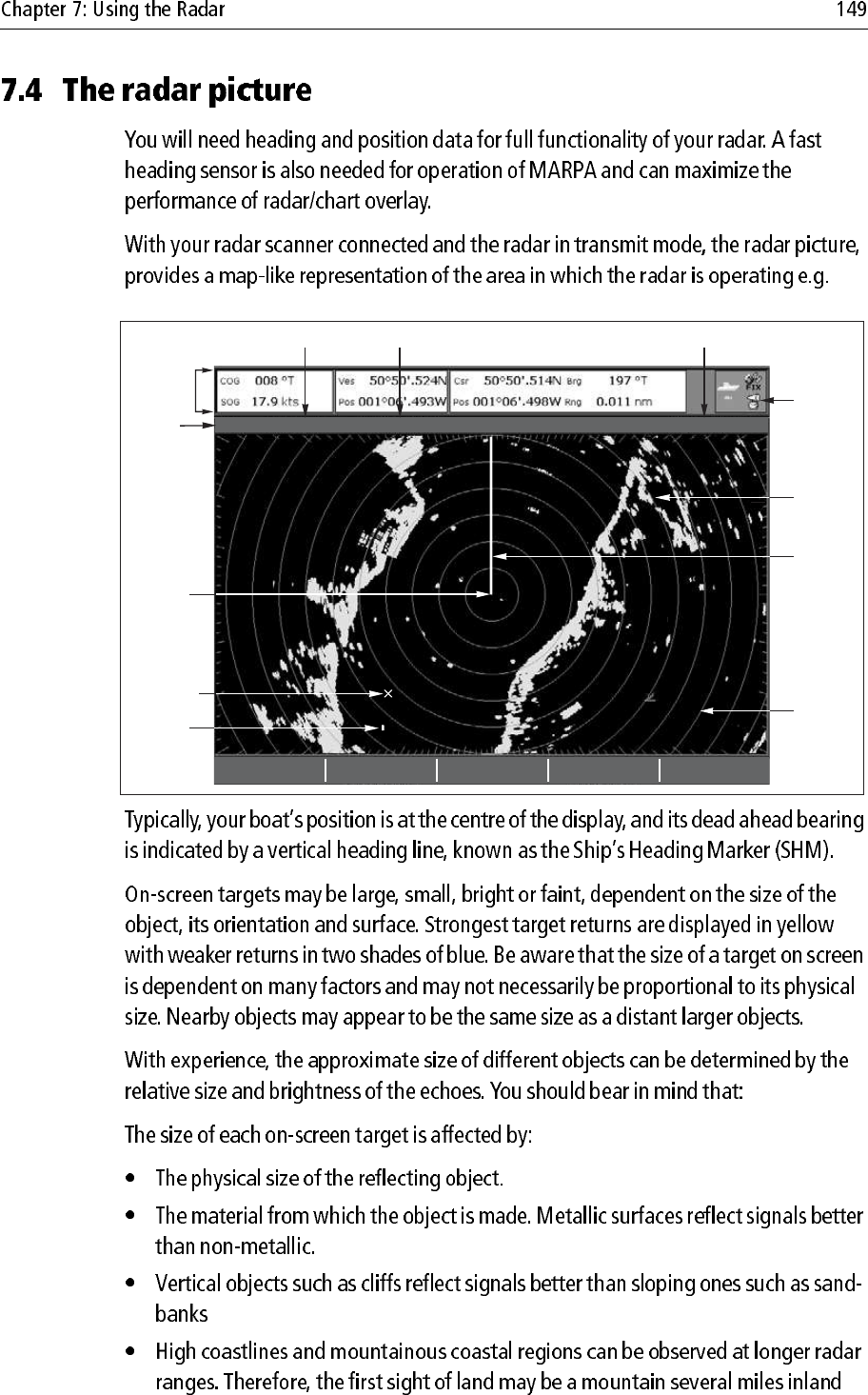
Orientation
Data bar
Surface
vessel
Waypoint
Ship's
heading
marker
Radar
status
icon
Range
ring
Land-
mass
Boat's
position
Range
Motion mode Range ring spacing
Note:
Notes: (1) If heading data becomes unavailable whilst in this mode, a warning
message will be shown, the status bar indicates North-Up in brackets
and the radar uses 0° heading in relative motion. When heading data
becomes available once more, North-Up mode is reinstated.
(2) It is not possible to select Head Up mode when the motion mode is set
to True.
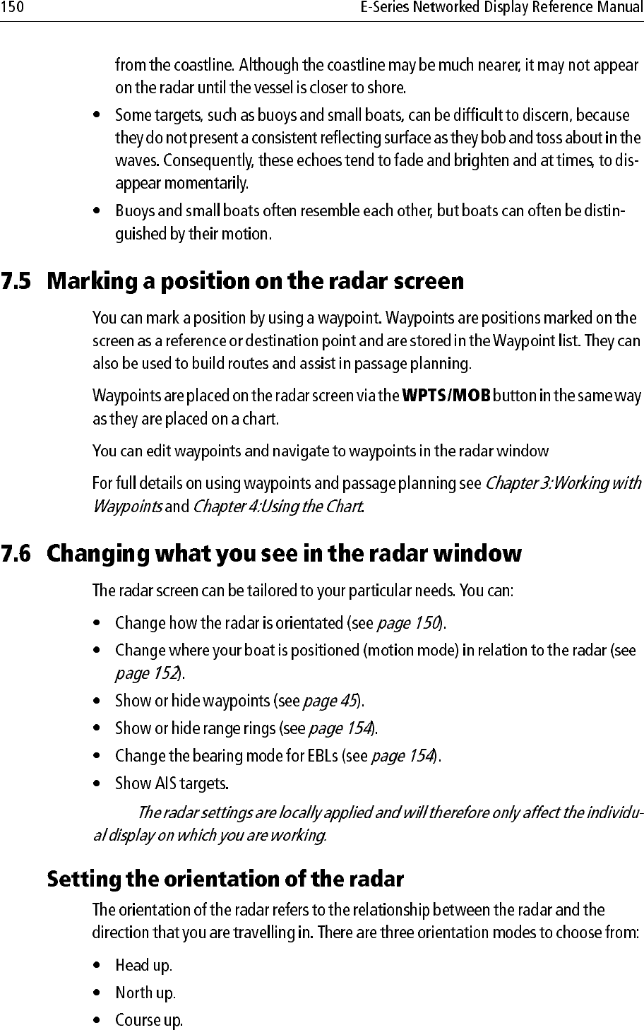
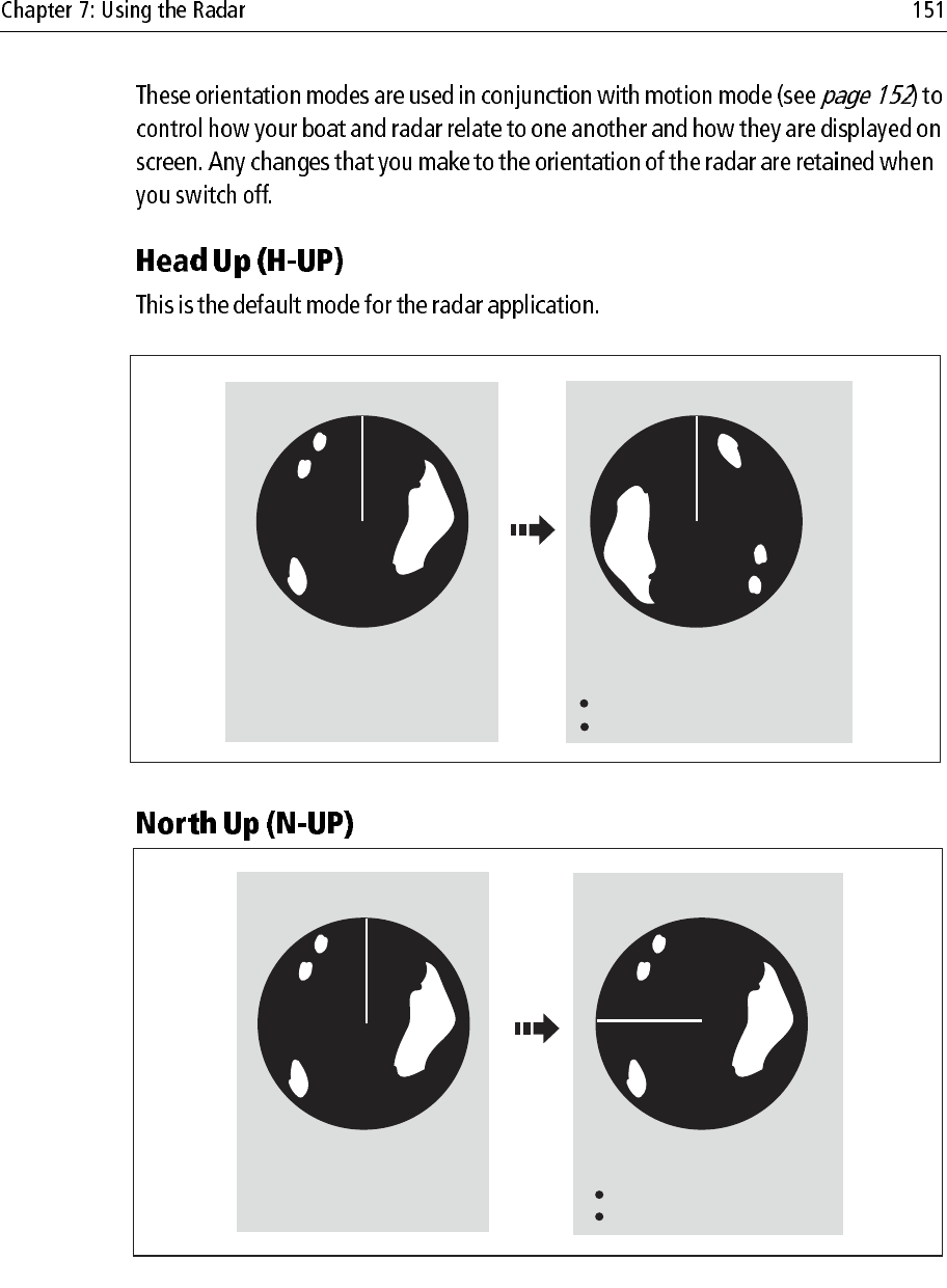
Ship's Heading Market (SHM)
(indicating the boat's current
heading) is upwards
As your boat's heading changes:
SHM fixed upwards
Radar picture rotates accordingly
N
N
e.g:
D8398_1
N
e.g:
True north at top
N
D8399_1
As your boat's heading changes:
Radar picture fixed (north up)
SHM rotates accordingly
Note:
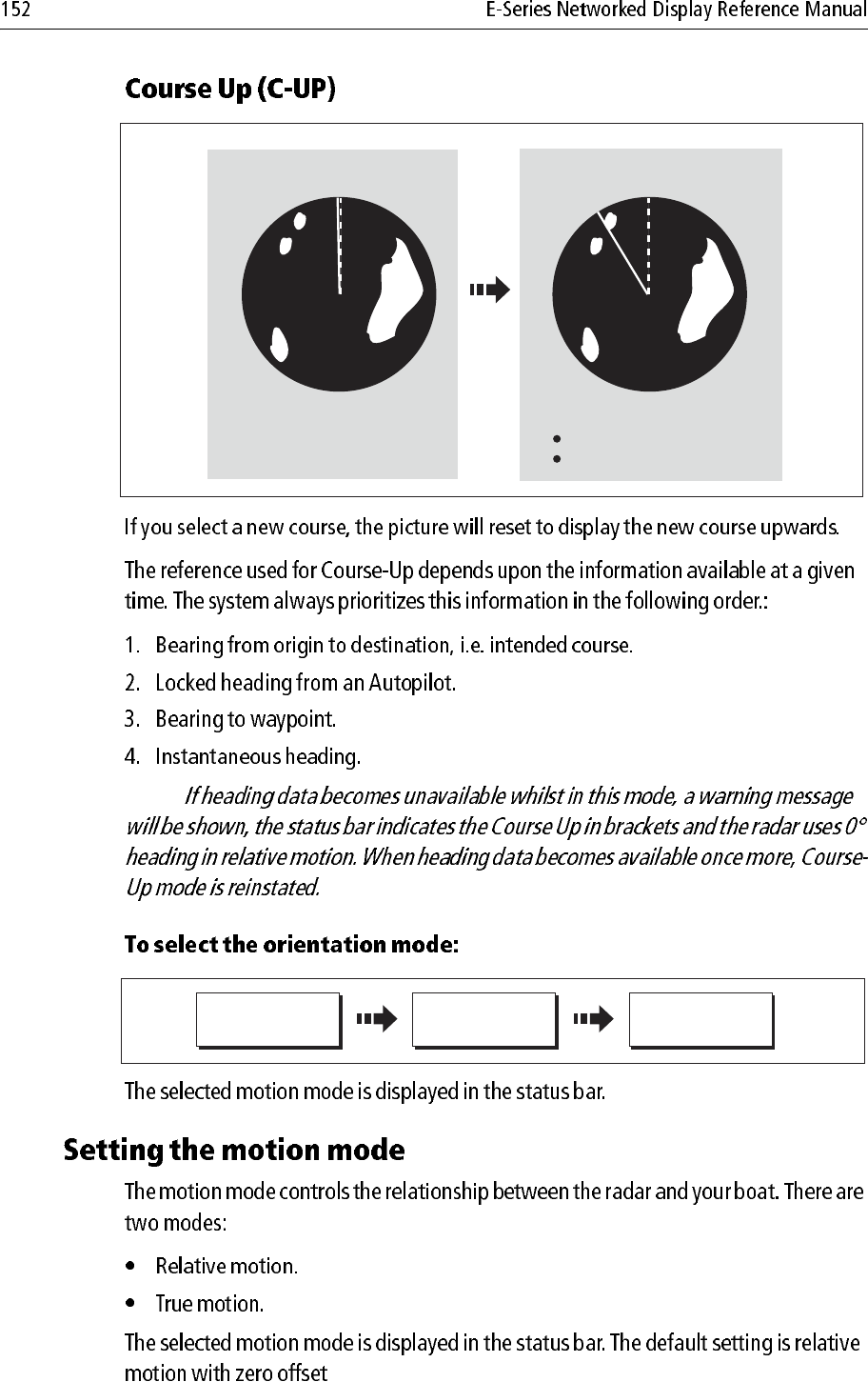
Current course upwards
NN
D8400_1
As your boat's heading changes:
Radar picture fixed
SHM rotates accordingly
e.g:
D6592-2
RADAR MODE &
ORIENTATION…
PRESENTATION… ORIENTATION
H-UP N-UP C-UP
Note:
Notes: (1)
(2)
D6842-2
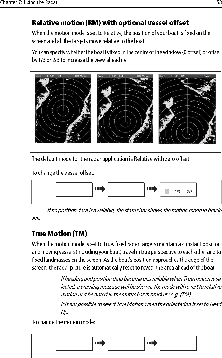
0 offset
2
/
3
offset
1
/
3
offset
D8805_1
RADAR MODE &
ORIENTATION…
PRESENTATION… VESSEL OFFSET
Toggle as required
0
D6838-2
RADAR MODE &
ORIENTATION…
PRESENTATION… MOTION MODE
TM RM
Toggle as required