Koden Electronics RB715A Marine Radar RA41C User Manual 05
Koden Electronics Co., Ltd Marine Radar RA41C 05
Contents
05
2
CHAPTER 2. USING RADAR FOR
THE FIRST TIME
This chapter describes basic information on radars and explains technical terms used
in radar operation for those who is using a radar for the first time.
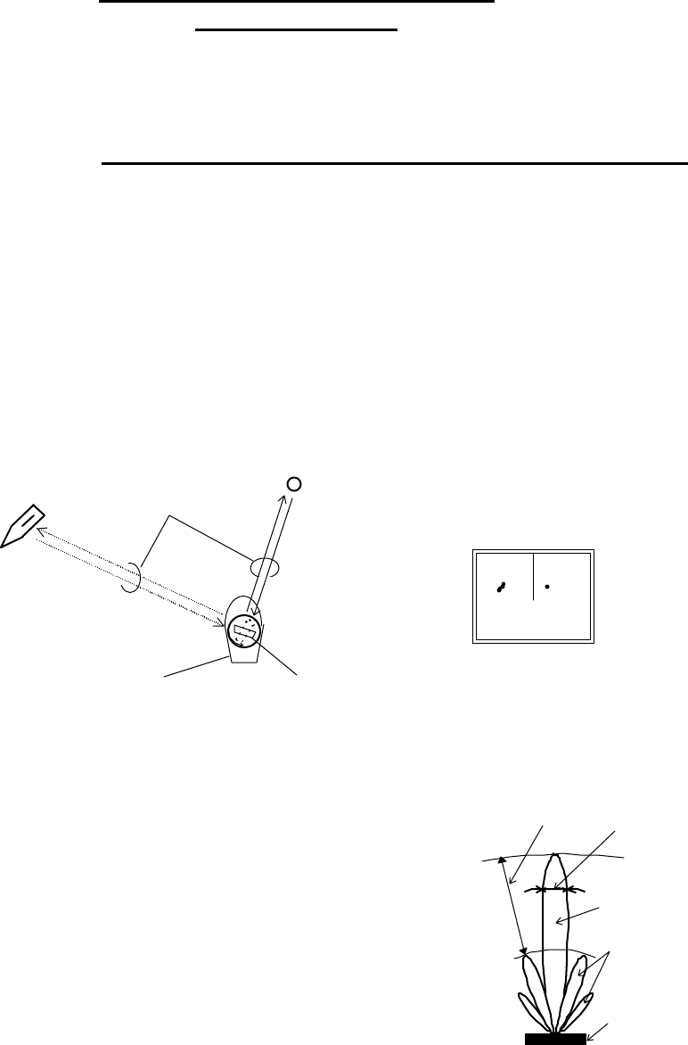
2.1 What is a radar ?
A marine radar is one of the navigation equipment installed on a ship. It emits a radio
wave in very high frequency called a microwave from its antenna and receives the reflected
radio wave from objects on the sea (e.g., other ships, buoys, and lands). The received radio
wave is converted into an electric signal which is displayed on a display screen to indicate
the presence of such objects. Although it is very difficult to find other ships or the destina-
tion coast with human eyes at night or in thick fog, a radar helps you detect objects on the
sea helping you avoid danger when sailing. The antenna turns 360 degrees as it radiates
waves, allowing you to grasp ambient conditions around your ship at a glance.
The radio wave radiated from the antenna is called a pulse wave and the radar performs
transmission and reception alternately. Several hundred to several thousand pulse waves
generally are transmitted while the antenna rotates one turn.
Antenna
There are many types of antennas generally used for a
radar. For example, these include a parabolic antenna and
a slotted-array antenna. The performance of the antenna
determines that of the radar. The dominant factors are the
antenna's beam width and side lobe level. The narrower
the beam width, the higher the resolution of the angle
direction. The lower the side lobe level, the fewer the effect
of a false echo.
Side lobe
A beam in one direction in which the strongest
radio wave is radiated from the antenna is called the
main lobe and beams in other directions are called
"side lobes". The side lobe level refers to the differ-
ence in level between the largest side lobe and the
main lobe.
Buoy
Other ship Radar wave
Your ship Antenna (Rotating)
Radar display
Fig.2-1 What is a radar?
Beam width
Side lobe
level
Main beam
Side lobe
Antenna
Fig.2-2 Antenna pattern
3
Beam width
A beam width is defined as the width of the main lobe at an angle where the radi-
ated power is halved as measured from the position from which the strongest radio
wave is radiated.
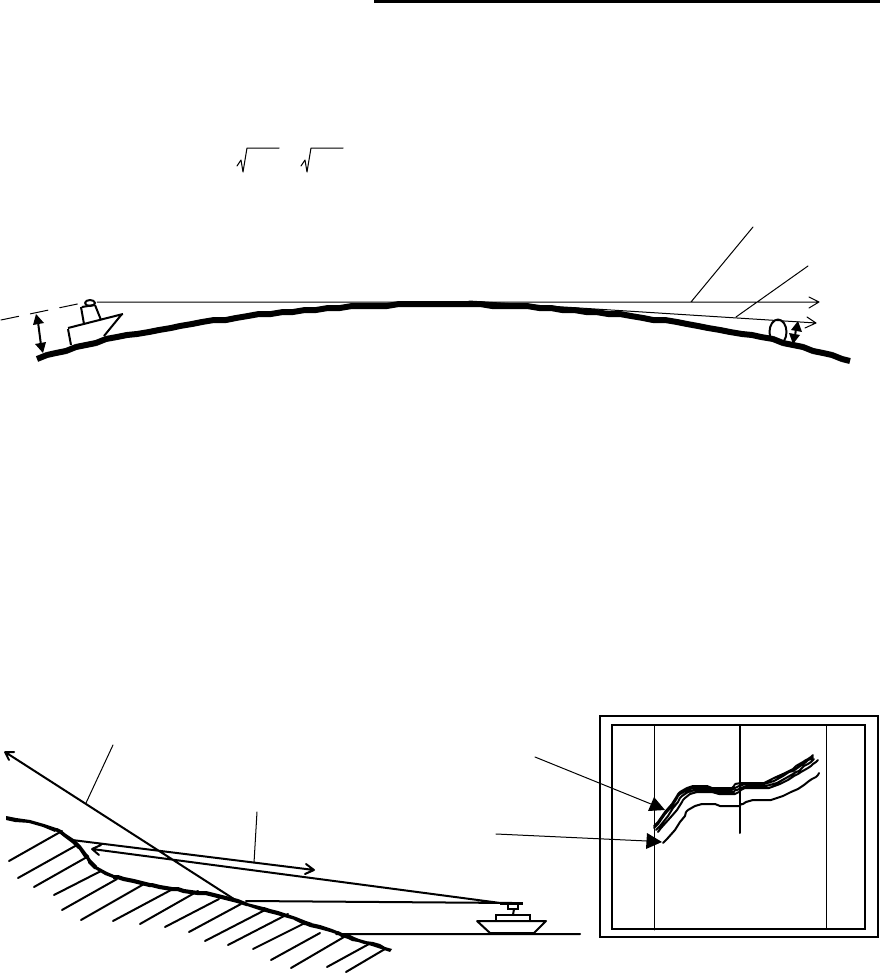
2.2 Characteristics of Radar Wave
Radio waves from the radar propagate while bending slightly along the terrestrial sur-
face. This characteristic varies dependent on the density of the atmospheric air. The sight
distance D of a radar generally is said to be approximately 6% longer than the optical sight
distance and is calculated using the equation below :
D (NM) = 2.22 ( h1 + h2 ) where, h1= antenna height in meters
h2= target height in meters
Fig.2-3 Radar wave
Targets difficult to display on screen
The intensity of the reflected wave from a target depends on the distance, height,
and size of the target, as well as its material and shape. Targets constructed with
FRP, wood, or other low-reflectance materials or those that have a small incident angle
are difficult to display on a screen. Therefore, FRP and wooden ships, sandy beaches,
and sandy or muddy shallows all are difficult to catch and require attention when
monitoring on the screen. Especially, coast lines on the radar image appear to be pre-
sent more apart from the ship than they are actually located. Therefore, it is important
not to misinterpret the available data.
Shadow zones of radar
Radar waves are characteristic in that they propagate straight ahead. Therefore,
if the ship's smokestack or mast is located near the antenna or there is a tall ship or
mountain at the side of the ship, such an object generates a shadow behind it. In this
Apparent coastline
Actual(invisible)
coastline
Invisible
Visible
3
1
HU
Fig.2-4 Targets difficult to display on screen
h1 h2
Line of sight
Radar Radio
Wave
Earth
4
case, some objects produce a complete shadow and some produce a partial shadow. In
an extreme case, the shadow of an object may extend to a position far away and can-
not be displayed on the screen at all. Since these shadows can be discovered when in-
stalling an antenna, the problem can be avoided by changing the place of antenna in-
stallation to minimize the shadow. Targets in shadow zones are difficult to display on
the screen.
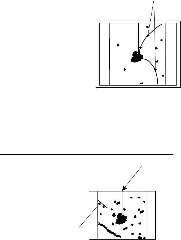
False echoes
A false echo of an actually nonexistent object may sometimes appear on the
screen when sailing. The following explains the cause of each of such phenomena.
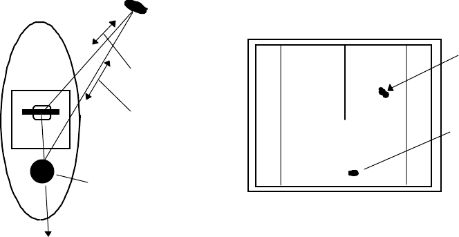
A. Ghost echoes
It sometimes happens that one large object near the ship appears at two different
bearings. One is the actual echo and other is a ghost echo generated as the wave is re-
reflected from the ship's own smokestack or mast. The former appears at the correct
distance and bearing on the screen and the latter appears behind the smokestack or
mast. This type of false echo is also generated by re-reflection of waves from bridges
and quay walls other than the ship itself.
B. Multiple echoes
If there is a large vertical reflecting plane near the ship as in the case when your
ship passes alongside a large ship, the wave is repeatedly reflected back and forth
between your ship and the other object. For this reason, two to four images appear on
the screen at equal intervals in the same bearing. A false echo that is generated by
such multiple reflections is called multiple echoes. In this case, an image appearing at
the nearest position is the real echo. Multiple echoes disappear as the ship moves
away from the reflecting object or its bearing changes. Therefore, it is not difficult to
determine the correct image.
Target
Direct reflection
path
Secondary
reflection path
Mast etc.
Real echo
Ghost echo
Direction of ghost echo
3
1
HU
Fig.2-5 False echoes of radar (Ghost echoes)
5
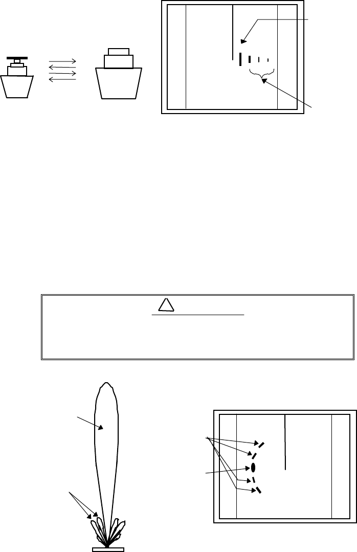
C. False echoes caused by side lobe
The radiant beam emitted from an antenna contains side lobes in directions other
than that of the main beam. Since the side lobe level is low, it in no way affects distant
targets. However, if there is a strong reflecting target near the ship, it sometimes ap-
pear as a circular-arc false echo on the screen.
When located near large targets such as land, the
ship's mast, etc. sometimes appears as a false
echo of circular-arc shape.
3
1
HU Real echo
Multiple
echoes
Fig.2-6 False echoes of radar (Multiple echoes)
3
1
HU
Antenna
Main beam
Side lobes
Real echo
False sidelobe
echoes
Fig.2-7 False echoes of radar (Caused by side lobe)
CAUTION
!
6
D. Distant false echoes caused by duct phenomenon
Depending on meteorological conditions, duct phenomenon sometimes occurs in
temperature inverting layers of air. In such a case, the wave propagates erratically
reaching a location surprisingly far away from the ship. In this case, a target present
at a distant location more than the radar's maximum distance range appears on the
screen presenting a false echo that can be misunderstood to be present nearer than
the actual position. This phenomenon is attributed to the fact that since echo from the
distant target arrives late, it gets out of the pulse repetition frequency and is displayed
on the screen as an echo in the next frequency. If the target distance changes as you
switch over the distance range, you can determine that it is a false echo.
Radar interference
If a radar operating in the same frequency exists near
your ship, interference noise may appear on the screen
that is caused by transmitted waves from that radar. This
interference appears in various ways. In most cases, how-
ever, it appears as spiral or radial patterns.
The RA40C/41C/42C radar has a function to elimi-
nate interference. Use of this function helps you minimize
interference.
2.3 Terms Specific to Radar
HM (Heading Marker)
This is a line-shaped marker used to indi-
cate the advancing direction of your ship.
North Mark
This marker indicates the north direction.
It is a short line approximately 1/6 of the
screen size.
3
1
HU
Radar inrterference
Fig.2-8 Radar interfer-
ence
0.75
0.25
HU
HM(Heading Marker)
North Mark
Fig.2-9 Heading Marker and
North Mark
7
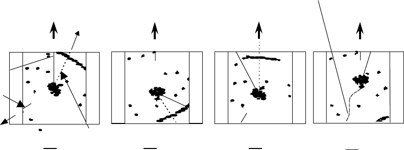
Display modes
This refers to a radar's display modes. There are four display modes depending on the
direction in which the top of the screen faces with respect to the ship.
Head Up (HU)
In this mode, the ship's heading always indicates the upward direction of the
screen. This mode lets you know the relative positions of your ship and other ships or
land.
North Up (NU)
In this mode, the north direction always indicates the upward direction of the
screen, allowing you to compare your ship position with a marine chart as you navi-
gate.
Course Up (CU)
The ship's heading in a course-up mode always indicates the upward direction of
the screen as the bearing toward the destination. In this mode, the ship can be ma-
neuvered to sail the shortest distance to the destination by steering it in such a way
that its heading marker always directs to the upward direction of the screen. If the
ship drifts due to tidal current, care must be taken because the fixed targets move to
other positions.
True Motion (TM)
In this mode, the ship is displayed as if it is moving on a marine chart while the
fixed targets such as islands and seashores are fixed in position. When the ship
reaches a certain position on the screen (approx. 2/3 of screen size), the ship is placed
back to the opposite side on the screen. (The top of the screen faces north.)
Note: Navigation equipment such as a gyrocompass or magnet compass must be con-
nected to your radar system before it can be operated in NU, CU, and TM modes.
(Refer to Section 3.9 for details on how to connect your radar to navigation equip-
ment.)
Ship's
Heading
North
Scheduled
course
HM
EBL
North
mark
HU NU CU TM
Ship's locus
(not displayed on screen)
North
North Scheduled
course
0.75 0.75 0.75 0. 25
TM
0.25
CU
0.25
NU
0. 25
HU
0.75
Fig.2-10 Display modes
8
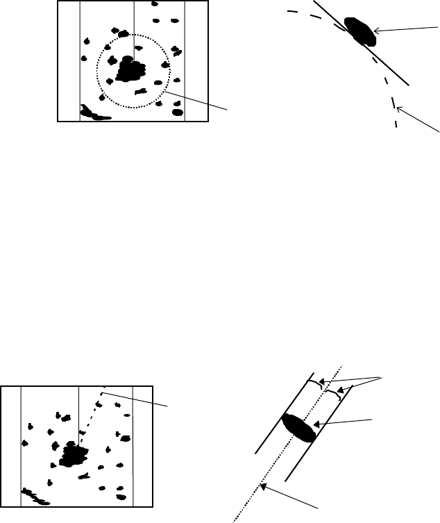
VRM (Variable Range Marker)
This is a circular-shaped marker whose size can be changed as desired. You can use
this marker when you want to examine the distance of an echo from your ship.
When measuring the distance of an echo from your ship, be sure to measure at a
point close to the center of the echo image on the screen.
EBL (Electronic Bearing Line)
This is a marker shaped like a straight line segment that can be changed to any direc-
tion centering around the ship position. Use this marker to examine the advancing direc-
tion of your ship and its relative angle with an echo. When measuring the angle of an echo,
position the marker at the center of the echo.
VRM
Echo
0.75
0.25
HU
VRM
Fig.2-11 VRM
0.75
0.25
HU EBL Echo
EBL
Equal intervals
Fig.2-12 EBL
9
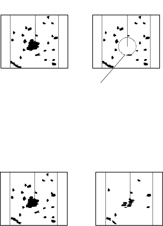
STC (Sensitivity Time Control)
Since echo signals received by the radar are strong when they are coming from a short
distance, it is difficult to compare signal strength between each reflected signal. To over-
come this difficulty, signal strength is adjusted in such a way that the received signal levels
coming from a short distance are lowered and those from a long distance are raised. This
function should prove useful when there are large reflected waves from sea surfaces during
rough weather.
FTC (Fast Time Constant)
When it rains or snows, fine noise may appear over the entire screen, making it diffi-
cult to identify echoes. In such a case, echo images on the screen can be made easily distin-
guishable by adjusting FTC.
0.75
0.25
HU
STC OFF STC ON
0.75
0.25
HU
Echo is suppressed
around center
Fig.2-13 STC
0.75
0.25
HU
FTC OFF FTC ON
0.75
0.25
HU
Small noises
are reduced.
Fig.2-14 FTC