Koden Electronics RB715A Marine Radar RA41C User Manual 16
Koden Electronics Co., Ltd Marine Radar RA41C 16
Contents
16
61
5.5.4 SETUP Menu
To be used for various settings and switching of the screen
•Common operations for the SETUP menu (Up to the point when "SETUP" menu is selected
from the main menu)
Press the "MENU" key and select "SETUP" from the displayed 4 main menus using the left-
right cursor. (The contents of the selected MENU will appear on a pull-down display in
accordance with the movement of the left-right cursor.)
MENU •••→• Left/Right
(Select SETUP)
When the above-mentioned operations have been conducted, the items of the SETUP menu
are vertically displayed. Further explanation about the SETUP menu will be conducted on the
assumption that this "common operation for the SETUP menu" has already been completed.
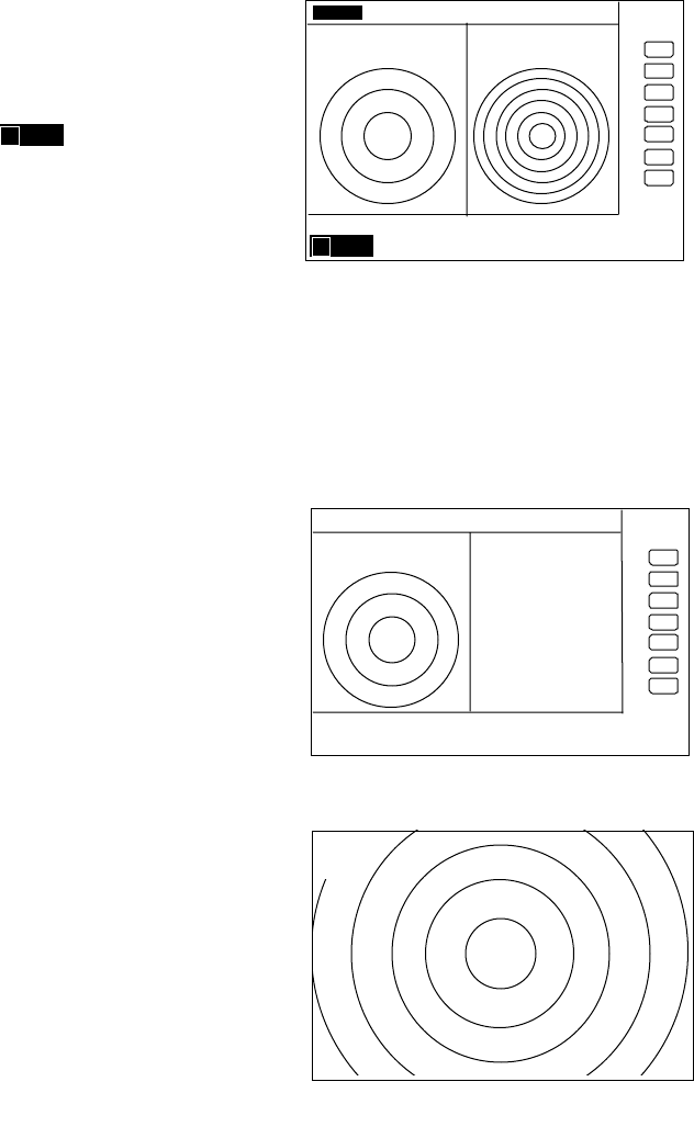
5.5.4.1 Initiating the screen display (WINDOW)
A function to switch the display method of the screen. A selection can be made from
among the 7 patterns of screen arrangements, from the ordinary PPI display to the 2-screen
PPI display, etc.
a) PPI screen
b) PPI screen & SEMI3D screen
c) PPI screen & PPI screen (Range can be operate in each screen.)
d) PPI screen & Navigation screen
e) All PPI screen (PPI, all the screen display.)
f) All PPI screen & All PPI screen(PPI & PPI, all the screen display.)
g) MOB screen
(1) Use the up-down cursor keys to select WINDOW from among the pull-down display items,
and press the "ENT" key.
(2) Select a screen to be displayed with the up-down cursor keys from among the above 7
items that are displayed beside the WINDOW item.
(3) The setting will be completed when the "ENT" key is pressed after the selection.
MARK
WINDOW >
SEL WIN >
PICTURE >
SYSTEM CHECK
CUSTOM >
. 75
.25
HU NAV ECHO SETUP
SEMI3D / PPI
PPI / PPI
PPI / NAV
ALL PPI
ALL PPI/PPI
MOB
•••••
SETUP
•
>>>>
•0.23NM
A
62
Up/Down →ENT →Up/Down →(Select PPI• →ENT •a•
•select WINDOW• →(Select PPI+SEMI3D•
→ENT •b•
→(Select PPI+PPI• →ENT •c•
→(Select PPI+NAV• →ENT •d•
→(Select ALL PPI• →ENT •e•
→(Select ALL PPI+PPI• →ENT
•f•
→(Select MOB• →ENT •g•
-Limitation of screen operation
SCREEN
ITEM
••• PPI/SEMI3D
PPI/NAV
PPI•PPI ALL PPI ALL PPI PPI MOB
RANGE •••••×
VRM1•EBL1 •••×××
VRM2•EBL2 •••×××
FL VRM2•EBL2 •×ו×××
RINGS ON/OFF •••••×
ZOOM•OFF CENT •×××××
///CSR •••••×
HDG OFF •••×•×
STERN M •••••×
NORTH M •••••×
GAIN•STC•FTC •••×××
TUNE •••×××
ST •••×××
GZ •••×××
SEL WIN ×וו×
TXON/OFF •••••×
• • Independent control at time as two screen.•Switching the screen is necessary (SEL WIN)•
• • It becomes simultaneous control at the time as two screen.
• • It can be used only at the time of PPI screen.
× • It can’t be used.
- Screen modes and Operations
63
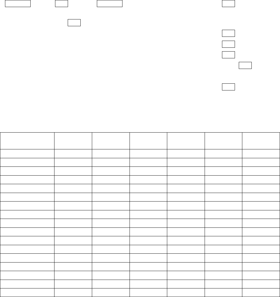
(a) PPI Screen
All functions can be used on this screen.
D‚V‚T
D‚Q‚T
‚g‚t
{
PPI Screen
64
(b) PPI/SEMI3D Screen
It becomes simultaneous control at the time as
two screen.
Note: All controls, such as EBLs, VRMs effects both
screen.
The ZOOM, OFF-C, FL EBL2, and FL VRM2 could
not be used on this mode. The "SEMI3D" screen
displays the center as ship's heading always.
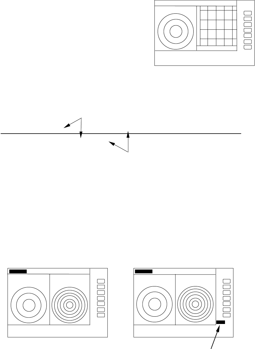
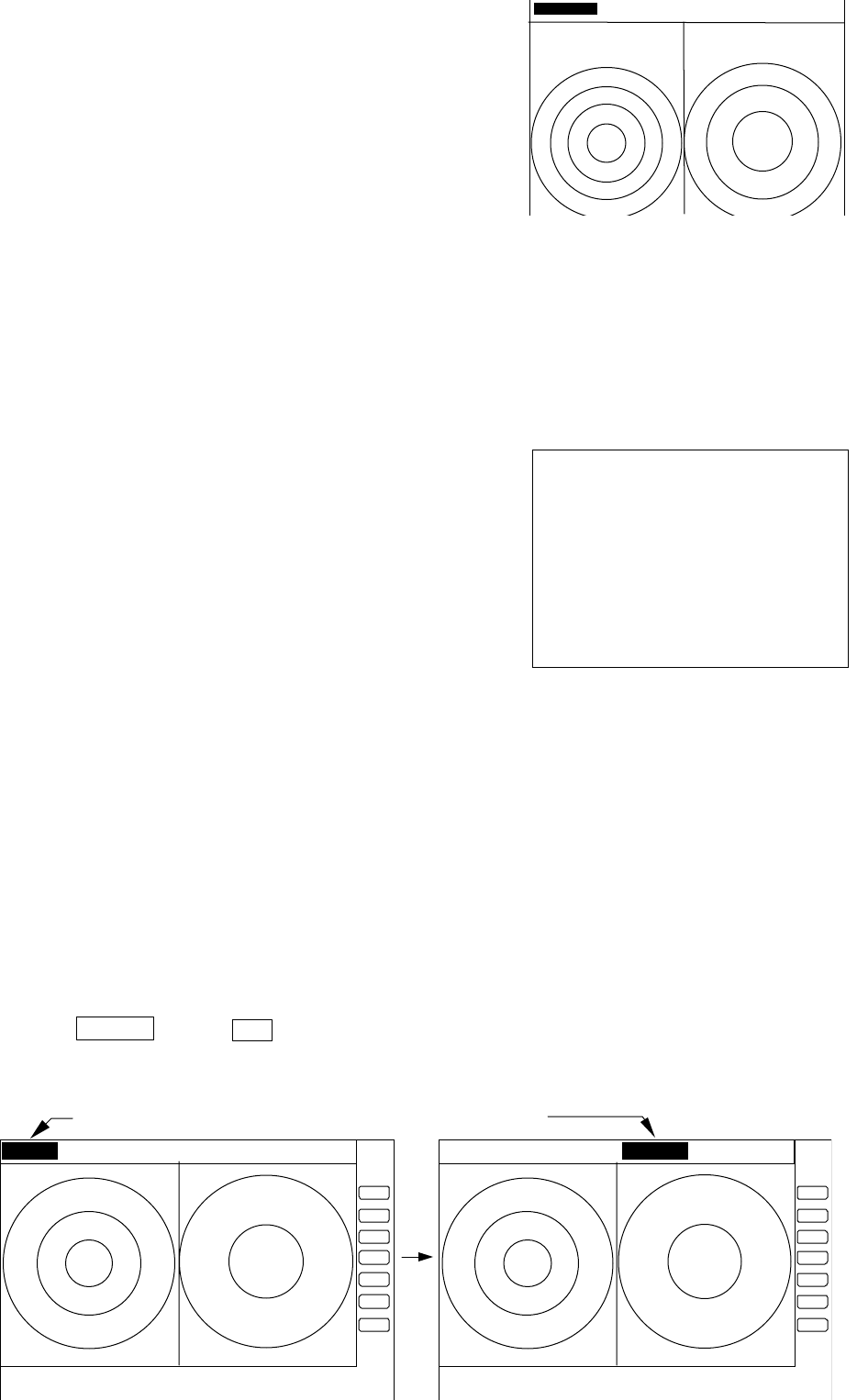
(c) PPI/PPI Screen
The radar picture is refreshed two antenna scanning for each PPI screen. Un-
refreshed screen picture is holded during the time.
Note: The radar picture is refreshed with two scanning interval for each screen. Right
screen picture is holded during refreshing left screen, left screen holded during
refreshing right screen. When your ship navigates in high speed, use PPI screen to
get fast refreshing picture.
Note: Functions ZOOM, OFF-C, FL-EBL2, and FL-VRM2 can not be used on this screen.
Note: The function RANGE, GAIN, STC, FTC, and GZ can be used for each screen
independently. The screen selected in "SEL WIN" that the range indicator displayed in
reverse can be controlled.
Note: The cross cursor displayed only on selected screen.
-Operation
a) Changing RANGE of LEFT screen
1) When the RIGHT range indicator displayed in reverse, change to LEFT screen with
"SEL WIN" function.
2) Press ”RANGE UP” or ”RANGE DOWN” key to change the LEFT screen RANGE.
D‚V‚T
D‚Q‚T ‚g‚t ‚r
{
280 320 000 040 080
PPI/SEM I3D Screen
LEFT screen /--------/*******/--------/******/--------/****** t→
→→
→
RIGHT screen ******* /--------/******/--------/******/--------/
picture drawing(refreshed)
displayed previous picture ( hold)
.75 .
25 HU S 24 6
{
G 55/35
S 35/AT
F 35/AT
LEFT screen selected
.75 .
25 HU S 24 6
{
G 55/35
S 35/AT
F 35/AT
GAIN adjustm ent for LEFT screen
L e ft GAIN indicates in reverse
65
b) Adjusting GAIN of LEFT screen.
1) When the RIGHT range indicator displayed in reverse, change to LEFT screen with
"SEL WIN" function.
2) Press the "GAIN" key, "G50" will displayed in reverse and ready for adjusting GAIN.
3) Adjust GAIN with the control knob.
Adjust STC and FTC in a same manner as GAIN.
Note: During adjustment of GAIN, STC, or FTC, radar picture refreshing is fixed to the
adjusting screen. Approximately 5 seconds errapsed after adjustment, radar picture
refreshing is return to normal.
c) Determining the distance with VRM1 on LEFT
screen.
1) When the RIGHT range indicator is displayed in
reverse, change to LEFT screen with "SEL WIN"
function.
2) Press the "VRM1" key, " " will be displayed in
reverse and ready for adjusting VRM1.
3) Determining the distance with the control knob.
Note: If operate the VRM1 on the RIGHT screen, VRM1
will move to the RIGHT screen.
Operate VRM2, EBL1, or EBL2 in a same manner as VRM1.
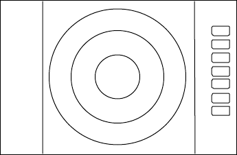
(d) PPI/NAV Screen
Note: The ZOOM, OFF-C, FL EBL2, and FL VRM2
can not be used on this screen.
(e) ALL PPI Screen
Note1: The RANGE, RINGS interval, and Display mode are
displayed on the upper-left of the screen.
Note2: When press the key except "MENU", "RANGE
UP/DOWN", "BRILL", and "POWER", return to PPI
screen.
G 55/35
S 35/AT
F 35/AT
1 0.00N M
Determining the distance with VRM1
on LEFT screen
.75 .25 HU S 6 1
{
D‚V‚T
D‚Q‚T ‚g‚t ‚r
{
NAV DISPLAY
WAY P 123.4 ‹
6.8 ‚m‚l
COURSE 2.38NM
XT E <<<
HDG 267.3 ‹
T
SPD 12.8KT
TEMP 20.8 ‹
C
DEPTH 58.3M
LAT/LON
34 ‹
08 D
22N
138 ‹
02 D
53E
PPI/NAV screen
{
. 75
. 25
HU S
ALL PPI screen
1 0.00NM
66
(f) ALL PPI/PPI Screen
Note1: The RANGE, RINGS interval, and Display mode
are displayed on the top of the screen.
Note2: When press the key except "MENU", "RANGE
UP/DOWN", "BRILL", and "POWER", return to
PPI/PPI screen.
Note3: The radar picture is refreshed with two
scanning interval for each screen. Right screen
picture is holded during refreshing left screen, left
screen holded during refreshing right screen. When
your ship navigates in high speed, use PPI screen to
get fast refreshing picture.
(g) MOB Screen
The MOB key has been pressed, the MOB position and
ship's position are displayed. If not, MOB position will be
displayed with bars( --.- )
Press MOB key to clear the MOB position and return
to previous screen. Press ENT key to return previous
screen with keeping the MOB position data.
5.5.4.2 Switching screens on PPI/PPI screen ( SEL WIN )
Switching to the desired screen for activation on a PPI/PPI screen display.
The "SEL WIN" function is switches the activated screen to effect the operation such as,
RANGE, GAIN, STC, FTC, VRM1/2, EBL1/2, and guard zone. The range indicator of activated
screen is displayed in reverse.
When "SEL WIN" is selected with the up-down cursor keys from among the pull- down
display items and the "ENT" key is pressed, activated screen will be changed to the opposite
screen.
Up/Down →••• ......................................................the opposite screen activated
•select SEL WIN•
D‚V‚T
D‚Q‚T ‚g‚t ‚r D‚Q‚T
D‚P‚Q‚T
{
ALL PPI PPI screen
MAN OVERBOARD
MOB POS
35 ‹
08 D
42N
139 ‹
03 D
33E
SHIP’S POS
37 ‹
12 D
42N
142 ‹
04 D
33E
PRESS MOB KEY TO DATA CLEAR
PRESS ENTER KEY TO RETURN
Range display on the active screen become a reverse display
.75 .25 S .5 .25 .75 .25 HU S .5 .25 .
67
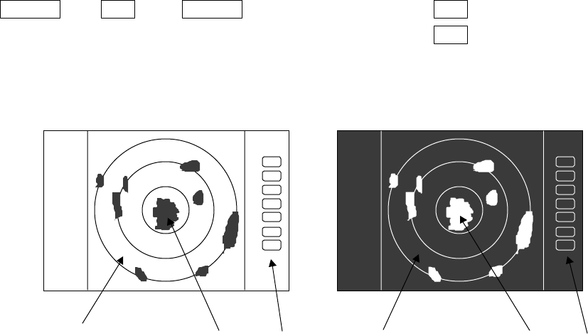
5.5.4.3 Changing the color of screen (PICTURE)
Changing the color of screen depending on weather and day / night environment
conditions will be effective for easy viewing .
When "PICTURE" is selected with the up-down cursor keys from among the pull- down
display items, select "DAY" and press "ENT" key to set to day display. Night display appears if
"NIGHT"
is selected
Up/Down →ENT →Up/Down →(select DAY•→ENT → day display
•select PICTURE•→(select NIGHT•→ENT → night display
βλυε ψελλοω ωηιτε βλαχκ γρεεν ρεδ
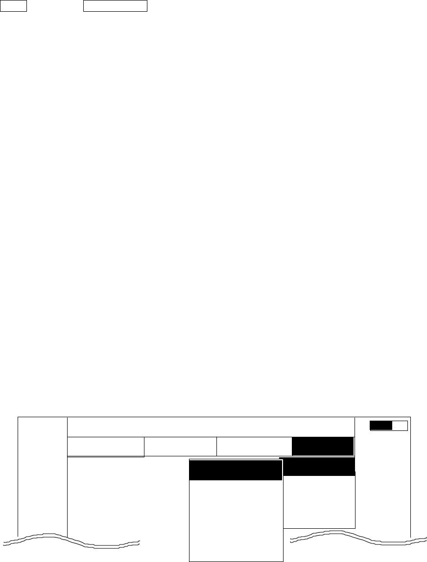
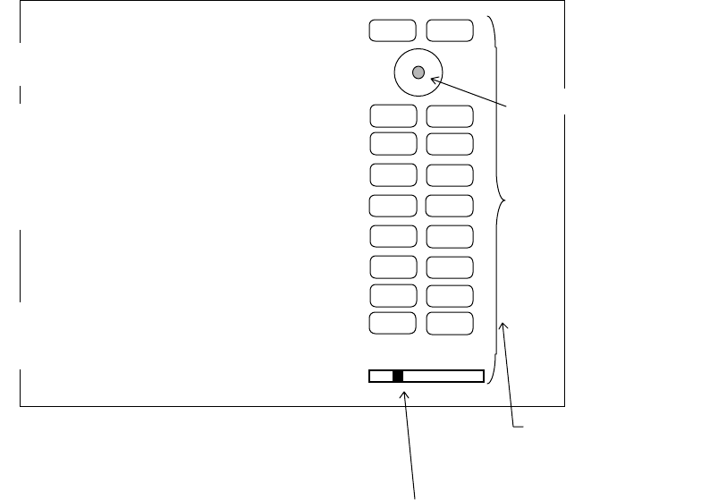
5.5.4.4 Fault Diagnosis by Self Check •SYSTEM CHECK)
Verifying the problem point by SYSTEM CHECK when, for example, some abnormality has
occurred.
(1) Select SYSTEM CHECK from the pull-down display items using up-down cursor key, and
press the “ENT” key.
(2) The system check screen will appear.
While watching the screen , check the following:
i) Whether all items are marked “OK”. (If any item is marked “NG”, the indicated location
may be faulty.)
ii) Press a front-panel key and see if the corresponding display on the screen is
highlighted.
iii) Turn the control knob and see if the lower-right indicator move to right or left.
(3) Press the POWER key to return to the previous screen
DAY display NIGHT display
75
. 25
HU
. 75
. 25
HU
68
a) ROM----------------------------- Indicates the ROM status.
b) RAM -------------------------------- Indicates the RAM status.
•• Backup memory-------------- Indicates the backup memory status.
•• Transmit trigger ------------- Indicates the signal line status for the trigger signal sent from the scanner
unit.
e• Bearing pulse------------------ Indicates the signal line status for the bearing signal sent fron the scanner
unit.
f) Heading pulse------------------- Indicates the signal line status for the bow signal sent from the scanner unit.
g) +5V voltage---------------------- Indicates the reference voltage status of the video circuit and its voltage
value.
(at video circuit) (normally about 5 V)
h) High voltage(at SU)---------- Indicates the status of th high voltage supplied from the display unit to the
scanner unit and its voltag value (normally about 250 V) at scanner unit.
i) High voltage(at DU) ---------- Indicates the status of th high voltage supplied from the display unit to the
scanner unit and its voltag value (normally about 250 V) at display unit.
j) Magnetron current---------- Indicates the status of the anode current flowing in the magnetron and its
current value.
k) Tuning voltage -------------- Indicates the status of the voltage used for tunning and its voltage value.
l) Cumulative usage time ---- Indicates the cumulative time your radar is used.
OPERATE : Duration of time during which the power supply is turned on.
TRANSMIT : Duration of time transmitting.
m) ROM version ---------------- Indicates the ROM software version.
n) Front-panel keys------------ As you press any front-panel key when the SYSTEM CHECK screen is on,
the corresponding key is highlighted on the screen by displaying it in reverse
video.
RNG U
RNG D
BRILL
AUTO
GAIN
STC
FTC
1
2
3
4
5
6
7
MOB
POWER
n)Indicates the operation
s
tatus of front-
p
anel ke
y
SYSTEM CHECK screen
ENTMENU
Indicates the control knob status.
Indicates the cursor status.
CONTROL KNOB
SYSTEM CHECK
MEMORY CHECK
a) ROM --------------------------------------- > ROM OK
b) RAM---------------------------------------- > RAM OK
c) Backup memory----------------------- > BACKUP OK
SIGNAL CHECK
d) Transmit trigger ----------------------- > (1) TRIGGER OK
e) Bearing pulse -------------------------- > (2) AZIMUTH OK
f) Heading pulse -------------------------- > (3) HM OK
g) +5Vvoltage(at video circuit)------> (4) +5V OK 5.2V
h) High voltage(at scanner) ---------- > (5) H.T. AT SU OK 253.2V
i) High voltage(at display)------------- > (6) H.T. AT DU OK 253.2V
j) Magnetron current--------------------- > (7) MAG. CUR. OK 2.1
k) Tuning voltage------------------------- > (8) TUNE OK
l) Cumulative usage time-----------> HOURMETER
Operation time --------------------- > OPERATE 12.0H
Transmit time ---------------------- > TRANSMIT 10.3H
m) ROM version -----------------------> ROM VERSION V1.00
PRESS POWER KEY TO RETURN