Koden Electronics RB715A Marine Radar RA41C User Manual 06
Koden Electronics Co., Ltd Marine Radar RA41C 06
Contents
06
10
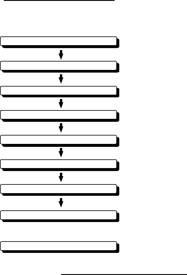
CHAPTER 3. INSTALLATION
This chapter describes procedures for installing the RA40C/41C/42C radar in your
ship and precautions to be observed during installation. Follow the procedure below to in-
stall the radar.
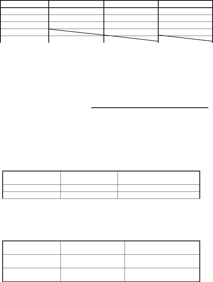
3.1 Checking Contents of Your Package
First, unpack your package and see if all of the following items are included.
RA40C RA41C RA42C
Item Q'TY Q'TY Q'TY
Display unit 1 (RF719A) 1 (RF719A) 1
(RF719A) Scanner unit 1 (RB714A) 1 (RB715A) 1
(RB716A) Display cover 1 1 1
Fuse 2 2 4
Interconnecting cable 1 (10 m) 1 (10 m) 1 (10 m)
Power supply cable 1 (2 m) 1 (2 m) 1 (2 m)
M10 hexagonal bolt 4 sets 4 sets 0
M12 hexagonal bolt 0 0 4 sets
Carbon brush 0 0 2
Checking contents of your package
Checking power supply voltage
Determining place of installation
Installing scanner unit
Installing display unit
Connecting cables
Adjustment
Connecting external equipment
When discarding Your radar
11
The package contains a 10m interconnecting cable as an accessory. Longer cable is
also available as an option as listed in Tab.3-1.
Tab.3-1 Optional Interconnecting Cable
In addition to the above components included with your package, the following items
are also required. Please prepare them separately.
Item QTY Remarks
Tapping screw or M5 bolt and nut 6 sets To install display unit
Grounding wire 1 Earth line for display unit
Grounding wire and crimp terminal 1 set Earth line for scanner unit
3.2 Checking Power Supply Voltage
3.2.1 Power Supply Requirements
For the RA40C/41C/42C radar to be operated normally, the power supply (battery)
detailed in Tab.3-2 is required. Note also that if the battery is discharged, its voltage may
fluctuate greatly, causing the radar to malfunction. When start up the radar system or start
transmitting, an additional rush current is required on the power line. Carefully check the
power supply system including wiring by using a circuit tester.
Tab.3-2 Power Supply Requirements
*A.C. power cannot be used
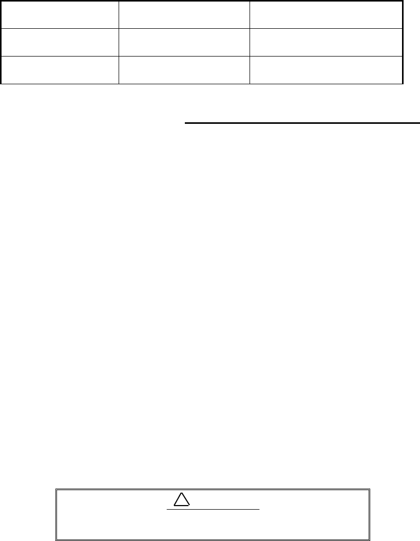
3.2.2 Fuse Replacement
For the RA40C/41C/42C radar to be operated safely, proper rating fuses must be
used. Tab.3.3 and Tab.3.4 are fuse rating tables for RA40C/41C and RA42C. Check them
and replace to the fuse in the package.
Tab.3-3 Supply Voltage to Fuse Table for RA40C/41C
Tab.3-4 Supply Voltage to Fuse Table for RA42C
RA40C RA41C RA42C
Cable length Product No. Product No. Product No.
15m 242J160680B 24Y159099B 24Y159169B
20m 242J160680C 24Y159099C 24Y159169C
25m 24Y159099D 24Y159169D
30m 242J160680D
Supply voltage
used Maximum current Allowable range of voltage
DC12V 5A 10.2-41.6V
DC24V 2.5A 10.2-41.6V
Supply voltage
used Main Fuse Motor Fuse
DC12V 8A/250V or 125V *
(6.3• x 32mm) T3.15A/250V or 125V *
(5• x 20mm)
DC24V 8A/250V or 125V
(6.3• x 32mm) T3.15A/250V or 125V
(5• x 20mm)
12
•••Note: Marked * fuses are in the set as standard.
3.3 Determining Place of Installation
3.3.1 Scanner unit
A radar's target detection capacity varies greatly depending on the fitted position of the
scanner. An ideal fitting position is a location high above the ship's keel line where there is
no obstacle all around the scanner. In an actual ship, such an ideal location is limited by
various factors. Therefore, consider the following suggestions when you determine the place
to install the scanner:
(a) Install scanner at a position as high as possible.
The higher the installation position, the longer the radio ranging distance.
Install the scanner at a position as high as possible after considering the ship's
hull structure and radar maintainability.
(b) Install scanner away from smoke-stack and mast
If the scanner is installed at the same height as the smoke-stack or mast,
radar waves may be blocked, creating shadow zones or generating false echoes.
Therefore, do not install the scanner at such a position.
(c) Install scanner forward away from obstacle.
To avoid creating shadow zones or generating false echoes, install the scan-
ner at a position nearer to the ship's bow away from obstacles. When installing
the scanner on a mast, position it in front of the mast. (If obstacles cannot be
avoided for the ship's structural reasons, refer to "Shifting away from obstacles"
described Page 13.)
(d) Do not install the scanner near hot or heat-generating items.
Do not install the scanner at a position where it may be subjected to smoke
or hot air from smokestacks or heat from lamps.
(e) Install the scanner away from antennas of other equipment.
Install the scanner as much away from the antennas of a direction finder,
radio transceiver, etc. as possible.
To eliminate the interference, install the scanner
away from the antenna of radio transceivers.
(f) Make the cable length as short as possible.
Keep the distance from the scanner to the display unit within the standard
cable length of 10 m. If you use longer cable for unavoidable reasons, limit the
cable length to a maximum of 30 m for RA40C and 100 m for RA41C/42C.
3.3.2 Display unit
The display unit can be installed on desktop, wall surface, or ceiling. Determine the
place to install the display unit that is convenient for navigation and radar operation after
considering the following suggestions:
Supply voltage
used Main Fuse Motor Fuse
DC12V 10A/250V or 125V
(6.3• x 32mm) 5A/250V or 125V
(5•x 20mm)
DC24V 8A/250V or 125V *
(6.3• x 32mm) T3.15A/250V or 125V *
(5• x 20mm)
!CAUTION
13
(a) A place where you can see the ship's bow when you raise your face from the
radar screen.
(b) A place where there is no direct sun-light to avoid display temperature up.
(c) A place where there is good ventilation and minimum vibration.
(d) A place where the display unit is apart more than the minimum safe dis-
tance from a magnet compass as listed in Tab.3-5 below.
Tab.3-5 Minimum Safe Distance from Magnetic Compass
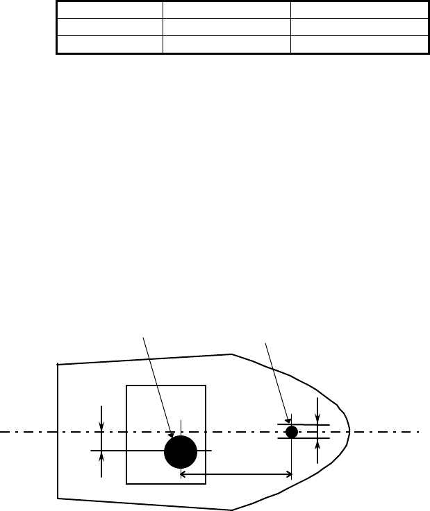
3.3.3 Shifting away from obstacles
!
!!
! Shifting from keel line
By shifting the scanner position from the keel line to the starboard side of
the ship, it is possible to move shadow zones to the port side which makes it
possible to keep clear vision in the bow direction. The distance to be shifted can
be obtained by calculation depending on the distance from the scanner to obsta-
cles using the following equation:
Ls=0.4R+D/2 [m] (when R<15m)
Ls=0.025R+D/2 [m] (when R>=15m)
where Ls = distance to be shifted from keel line
D = diameter of obstacle on keel line
R = distance from scanner to obstacle
"
""
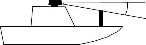
" Obtaining sufficient dip angle
Raise the scanner position so that there is a sufficient dip angle θ available
between the line of sight from the scanner to the obstacle and the horizontal
line. By raising the dip angle above 5°, it is possible to prevent mid- and long-
distance shadow zones. The radar cannot detect objects below the line of sight.
Master compass Steering compass
Scanner unit 2.0m 1.4m
Display unit 2.0m 1.4m
Ls
R
D
Scanner Unit Obstacle
Keel line
Fig.3-1 Shifting from keel line
14
Horizontal line
Line of sight
θ
Fig.3-2 Obtaining sufficient dip angle
15
3.4 Installing Scanner Unit
When you have decided the place of installation, install the scanner unit. If a mount
base like the one shown below is available, it may be easier to install the scanner. If such a
mount base is not available in your ship, you may install the scanner directly to the roof,
etc. In such a case, pay attention to the water drain tube located at the bottom of the scan-
ner unit during installation.
Note : When the radar mast or mounting bracket has a curvature of more than 2mm, repair
it or use spacers.
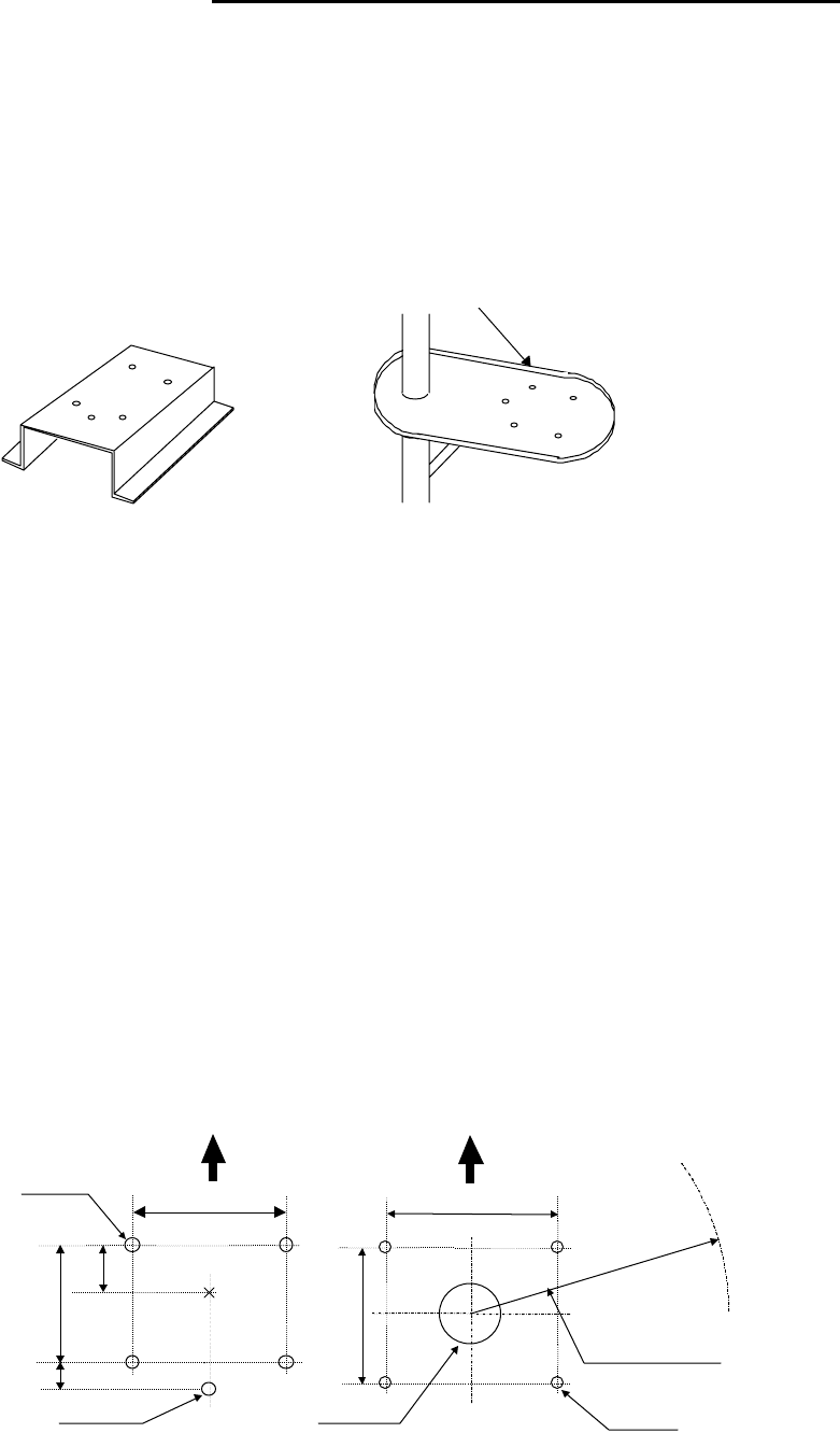
Referring to Fig.3-4, open holes in diameter of 12 mm (0.47 in.) at five locations in the
mount base and use these holes to fix the scanner unit to the mount base with hexagonal
bolts. (Use the template included with this manual.) The bolts included with your radar
equipment will suffice for mount base thickness of 9 to 14 mm (0.35 to 0.55 in.). If the
mount base is thicker or thinner than this, prepare bolts listed in Tab.3-6.
Use sealing of silicon when you prevent the bolts from becoming loose. Radome may be
broken if you use locking putty.
Do not use an edge that might trap water.
Fig.3-3 Mount base
Center
214
170
12φ × 4
Unit:mm
65
Forward
(8.43 in.)
(2.56 in.)
(0.47 in.)
35
(1.38in.)
For air tube
(6.69 in.)
15φ (0.59 in.)
199
(7.83 in.)
Forward
185
(7.28 in.) Rotation Radius
R550 (3 ft antenna)
R700 (4 ft antenna)
14φ × 4
(0.55 in.)
Cable inlet
100φ (3.97 in.)
RA41C
Radome scanner RA42C
Open scanner
Fig.3-4 Hole positions for mounting scanner
16
Tab.3-6 Bolts for Mounting Scanner Unit
3.5 Installing Antenna Unit
Center
140
140
12φ × 5
60
Forward
(5.51 in.)
(2.36 in.)
(0.47 in.)
30
(1.18in.) For air tube
(5.51 in.)
••••••RA40C • Radome scanner
Center
214
170
12φ × 4
Unit:mm
65
Forward
(8.43 in.)
(2.56 in.)
(0.47 in.)
35
(1.38in.)
For air tube
(6.69 in.)
15φ (0.59 in.)
199
(7.83 in.)
Forward
185
(7.28 in.) Rotation Radius
R550 (3 ft antenna)
R700 (4 ft antenna)
14φ × 4
(0.55 in.)
Cable inlet
100φ (3.97 in.)
RA41
Radome scanner RA42
Open scanner
Fig.3-4 Hole positions for mounting scanner
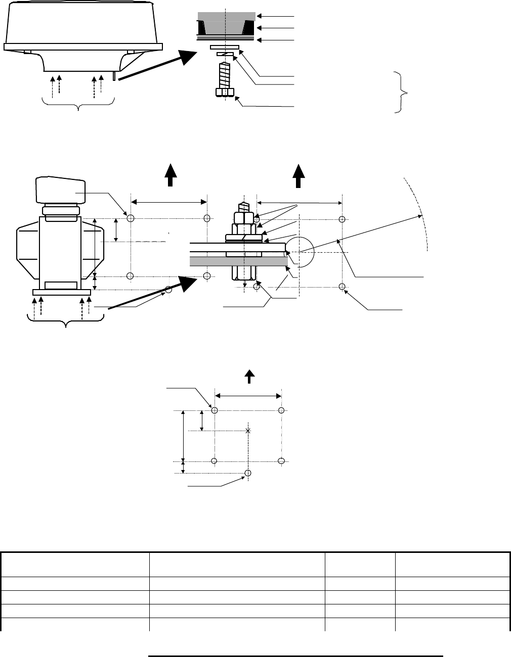
Fix four screws
Mount base
Washer
Spring washer
M10 Hexagonal bolt
Radome(bottom)
Chassis
Included
Fix four screws
RA40C/41C Radome scanner
RA42C Open scanner
Double nuts
Spring washer
Washer
M12 Hexagonal bolt
Mount base
Scanner base
Fig.3-5 Fixing Scanner Unit
Thickness of
mount base Bolts necessary to
fix radome scanner Material Remarks
1-4mm(0.04-0.16 in.) M10/M12 × 15 (1.5mm pitch) Stainless
4-9mm(0.16-0.35 in.) M10/M12 × 20 (1.5mm pitch) Stainless
9-14mm(0.35-0.55 in.) M10/M12 × 25 (1.5mm pitch) Stainless Included with radar
14-19mm(0.55-0.75 in.) M10/M12 × 30 (1.5mm pitch) Stainless
17
Remove the protective cap covering the rotary coupler on the top of the scanner. Match
the antenna radiation direction to direction of the arrow markings on the rotation base and
fix the antenna in position using the four M8 accessory bolts.
3.6 Installing Display Unit
After you have finished installing the scanner unit, install the display unit in the same
way. Choose the proper bolt length according to the thickness of the surface on which you
are going to install the display unit. Hole diameter is different using bolts from using tap-
ping screw. When using tapping screw, open holes in adequate holes. When using bolts and
nuts, open holes in diameter of 6 mm (0.24 in.). When you have opened holes, install the
pedestal part first and then the display unit.
Note : When you install the display by flush mount, refer to appendix "OUTLINE DRAWING".
Slide off four triangle corner cover, and fix the display unit to the panel with screws. After
fixing the display unit, put on corner covers to the corner of the display unit. See APPENDIX.
360
84
Fitting hole
(14.17 in.)
(3.31 in.)
Hole diameter
6mm : Bolts and Nuts
Adequate : Tapping screws
Recommended screw
M5 or equivalent
Unit : mm
47 (1.85 in.)
37 (1.46 in.)
60
(2.36 in.)
240
(9.45 in.)
60
(2.36 in.)
Forward
Fig.3-6 Hole positions for display unit
Antenna radiation surface
Arrow

18
Avoid a display from operating under direct sun-
light. It becomes high temperature at inside of dis-
play and display may be broken.
!WARNING
19
3.7 Connecting Cables
Lay cables firmly in place by following the instructions below.
Note1: Do not bind the cable for the radar collectively with cables of other
equipment (especially power supply cable).
Note2: Leave clearance near the inlet of the display so you can remove the dis-
play unit easily. This facilitates installation and maintenance of the dis-
play unit. (Refer to Appendix.)
Note3: Because the cable has a connector fitted on the display and scanner side,
if it is necessary to pass cable through a narrow path, fix the scanner-side
connector vertically using vinyl tape before passing cable through the
path.
Note4: Lay cable along the ship's hull or wall surface and attach it in place at
intervals of about 40 cm.
3.7.0 Interconnecting cable (RA40C Radome scanner) (See Fig.3-8-1)
!Ensure that the radar is off. Connect the cable to the receptacle labeled "SCANNER"
on the rear panel of the display unit.
"Next, remove the upper part of the radome from the scanner unit. Avoid bumping it
against the antenna by lifting vertically. (There are three fixing screws.)
#Remove the tape fixing the antenna.
$Remove the shield cover located on the astern side. (There are three fixing screws.)
%Remove the cable clamping plate and rubber ring, pass cable through the introduc-
tion opening, put the rubber ring from both ends of it, and clamp the cable to the
scanner unit with screws via the fixing plate. Plug the connector fitted to the cable
into the X1 connector on the PCB.
&Replace the aluminum cover. At this time, attach a cable shield onto a ditch with
the aluminum cover. However, be careful that the cable will not be caught up be-
tween the main unit and cover.
•• ' Replace the upper part of the radome. Be careful not to bump it against the antenna
in
the same way as when removing it. Make sure that the cover is fitted in the correct
direc-
tion as shown in Fig.3-7-1. The upper and lower parts of the radome each have
three
markings indicating screw positions. Align the upper and lower positions as you
mount
the radome.
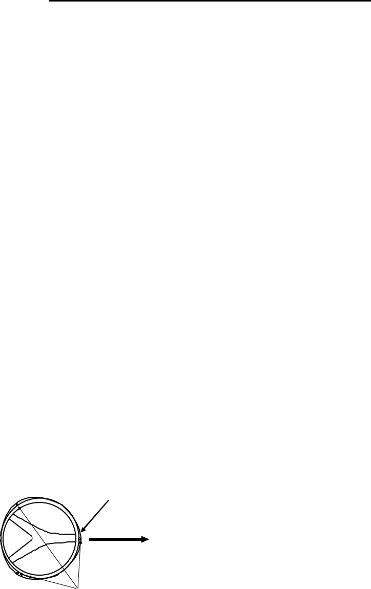
3.7.1 Interconnecting cable (RA41C Radome scanner) (See Fig.3-8-2)
!Ensure that the radar is off. Connect the cable to the receptacle labeled "SCANNER"
on the rear panel of the display unit.
"Next, remove the upper part of the radome from the scanner unit. Avoid bumping it
against the antenna by lifting vertically. (There are four fixing screws.)
#Remove the tape fixing the antenna.
Fixing screws
Ship's
heading
Logo seal on
side wall
Fig.3-7-1 Fitting Cover (RA40C)
20
$Remove the shield cover located on the astern side. (There are four fixing screws.)
%Remove the cable clamping plate and rubber ring, pass cable through the introduc-
tion opening, put the rubber ring from both ends of it, and clamp the cable to the
scanner unit with screws via the fixing plate. Connect 7-pin connector to X11 and
9-pin connector to X12 of PCB.
&Replace the aluminum cover. At this time, attach a cable shield onto a ditch with
the aluminum cover. However, be careful that the cable will not be caught up be-
tween the main unit and cover.
'Replace the upper part of the radome. Be careful not to bump it against the an-
tenna in the same way as when removing it. Make sure that the cover is fitted in the
correct direction as shown in Fig.3-7-2. The upper and lower parts of the radome
each have four markings indicating screw positions. Align the upper and lower po-
sitions as you mount the radome.
Ship's
heading
Logo seal on
side wall
Fix four screws
Cable inlet
Fig.3-7-2 Fitting cover (RA41C)
21
A
ntenna
Stern side Shield cover
Cable shield
Radome (bottom)
Fixing plate
Rubber ring
Interconnecting cable
Fix connector on
PCB(X1)
X1 (Connect here)
Radome (bottom)
PCB
Inner shield
Fig.3-8-1 Fitting interconnecting cable (RA40C)
22
Fix connector on
PCB(X11, X12)
Antenna
Stern side Shield cover
Cable shield
Radome (bottom)
Fixing plate
Rubber ring
Interconnecting cable
X12 (Connect here)
Radome (bottom)
PCB
Inner shield
X11 (Connect here)
Fig.3-8-2 Fitting interconnecting cable (RA41C)
23
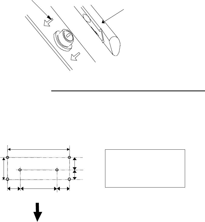
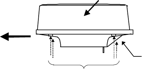
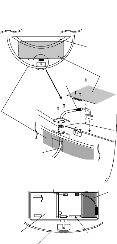
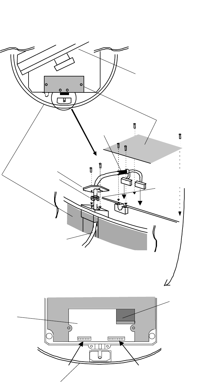
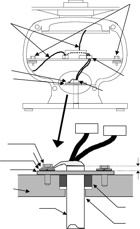
3.7.2 Interconnecting cable (RA42C Open scanner) (See Fig.3-9)
!Ensure that the radar is off. Connect the cable to the receptacle labeled "SCANNER"
on the rear panel of the display unit.
"Use a T-wrench to remove the back covers of scanner unit.
#Remove the two bolts securing the transceiver; pull out the transceiver after removing
two connectors.(to Motor(X1), to Heading switch (X2))
$Remove the four bolts securing the fixing plate at the cable entrance.
%Remove the metal fixing plate, rubber seal and washer that secure the cable. Pass the
cable through as shown in the diagram below; replace the above items and tighten the
bolts.
&Return the transceiver to its original position and secure it with the removed bolts.
'Connect 7-pin connector to X11 and 9-pin connector to X12 of PCB. And connect two
connector that removed at #.
(Refit the scanner covers.
Take care not to pinch the cable when refitting the cover.
24
TR unit fixing bolts
Remove connector
Fixing bolt
Fixing plate
Inter-connection cable
Clumper
5-10 mm
Fixing bolt
Cable shield terminal
Washer
Fixing plate
Scanner unit
Inter-connection cable Rubber
Cable inlet
Fig.3-9 Fitting interconnecting cable
25
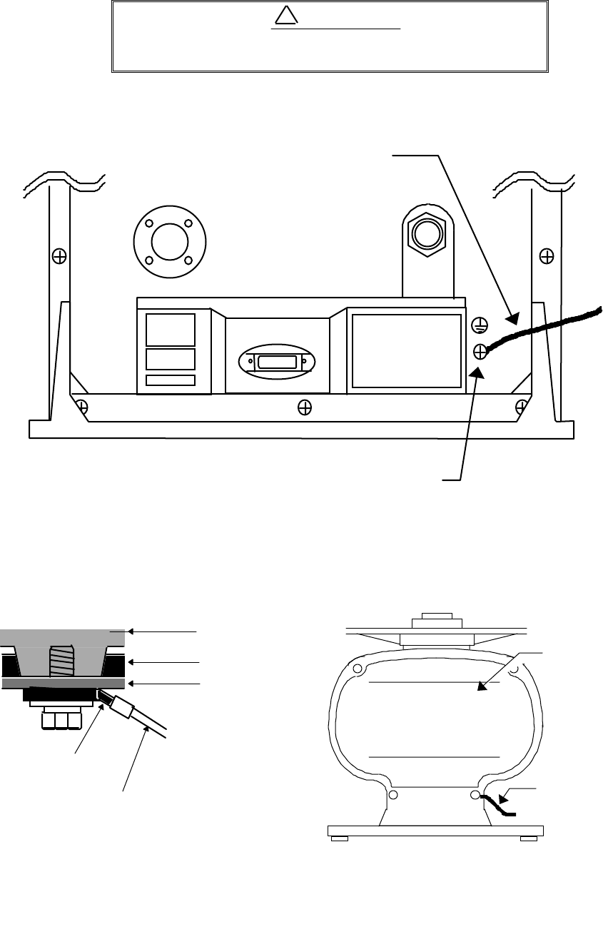
3.7.3 Grounding wire
Connect grounding wire before connecting power
supply cable. Leakage current is too high.
Connect grounding wire from the grounding terminal on the rear panel of the display
unit to the ship's hull as shown below.
Connect grounding wire from one of the bolts you have attached when installing the
scanner unit to the ship's hull as shown in Fig.3-11. (The crimp terminal and grounding
wire are not included with the radar equipment.)
SCANNER POWER
OPTION
Grounding terminal
Grounding wire
Fig.3-10 Grounding display unit to earth
Mount base
Radome
(
bottom
Chassis
→
→→
→
To shi
p
's hull
Crim
p
terminal
Grounding wire
Radome scanner
Groundin
g
wire
→
→→
→To shi
p
’s hull
Scanner cover
O
p
en scanner
!WARNING
Fig.3-11 Grounding scanner unit to earth
26
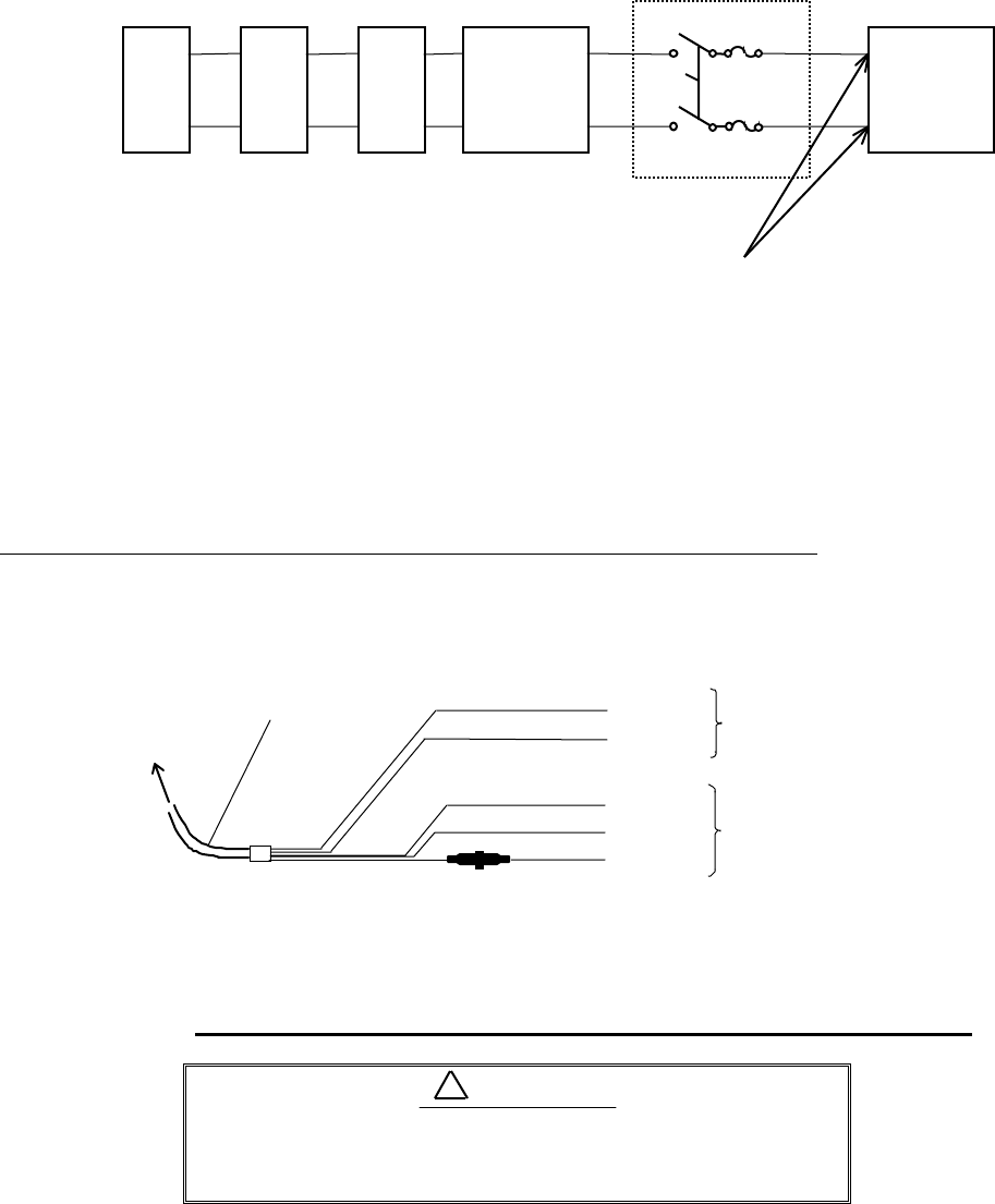
3.7.4 Power supply cable
Power is fed through a knife switch ( or circuit breaker) and protective fuses, as shown
in below.
WARNING: Do not apply over 41.6V to Radar
or Radar may be broken.
Fit the power supply cable (included with your radar) to the receptacle labeled "POWER"
on the rear panel of the display unit. And connect to power supply as followings. (When you
do not connect external equipment, put tape on red and green wire.)
Place the Fuse and connection part where there is no water splash and dry area.
When extend the power supply cable, use a suitable cable as below.
Ship's Power Voltage Cable conductor Cable max. length
cross section
12Vdc 3.5 mm23 m
6.0 mm25 m
24Vdc 2.0 mm26 m
3.5 mm210 m
3.8 Adjustment
Be sure to operate the following adjustment. If this
is not adjusted properly, the radar picture does not
display true image.
When you have finished installing the scanner and display units and connecting cables,
turn on the power to the display and scanner units and check to see if they operate nor-
mally without problem. Then make adjustments as detailed below and check to see if the
units operate normally again.
White
Black
Gray
Green
Red
Power supply cable
To dis
p
la
y
unit
DC+
DC-
Ground
NMEA-
NMEA+ To external
equipment
To power supply
Fig.3-12 Power supply cable
!CAUTION
Generator Switchboard Charger Storage
Battery
12/24V
Main switch panel
(Knife Switch with
Fses)
Radar Display
Unit
DC voltage
reference points
27
! TUNING Refer to Adjusting tuning circuit in 5.5.4.5.4
" HEADING DIRECTION Refer to Adjusting angle in 5.5.4.5.4
# DISTANCE Refer to Adjusting distance in 5.5.4.5.4
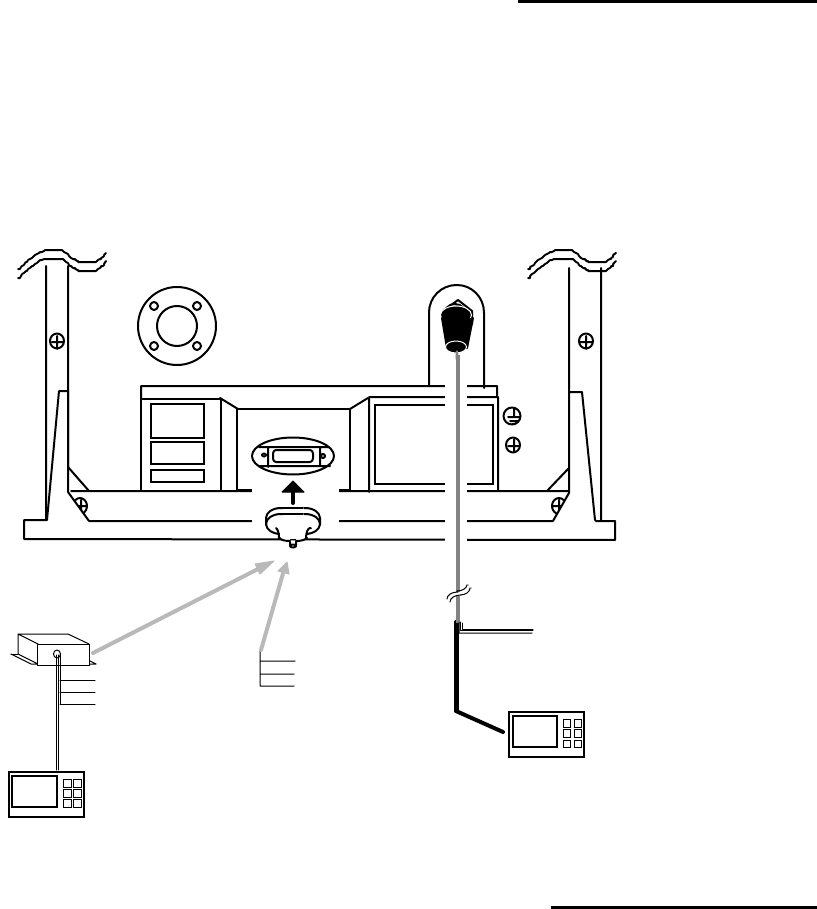
3.9 Connecting External Equipment to Display Unit
The display unit has two channels of NMEA input. One is standard in power cable. The
other is necessary to connect optional parts (Junction box with OPTION cable).
OPTION connector is located at display’s rear panel for connecting external equipment
such as a GPS, LORAN, or gyro compass. You must have an Junction box with OPTION ca-
ble. (Refer to CHAPTER 8 (4) External interface.)
Note: SIN/COS and MOB signals cannot be used on Junction Box.
Junction box with OPTION cable (Order No. RZ704A)
3.10 Countermeasure for Electromagnetic Interference
RA40C/41C/42C radar provides shields in the units and the inter-unit connection ca-
ble. When the radar, however, is closely installed to radio equipment such as VHF trans-
ceiver, UHF transceiver, etc., or the radar and/or radio equipment are not sufficiently
grounded to the hull or ship's earth, the radar may happen to cause EMI trouble.
Followings are general procedures for reducing EMI due to radars. When installing ra-
dars, refer to them, and also check the radio equipment EMI trouble with operating the ra-
dar and radio equipment.
SCANNER POWER
OPTION
OPTION cableJunction box*note
POWER cable
External NMEA equipment
External NMEA equipment
Green :NMEA-
Red :NMEA+
To power supply
Other radar,
slave monitor,
External buzzer,
Gyro I/F
Other radar,
slave monitor,
External buzzer,
Gyro I/F,
SIN/COS.
MOB(NMEA out)
Fig.3-13 Connecting external equipment to display unit
28
(1) Installation Place of Radar
The display unit, scanner unit and inter-unit connection cable should be located
apart from the main unit, feeder, antenna coupler and antenna of radio equipment as
far as possible.
Especially, proper installation of the feeder, antenna coupler and antenna of radio
equipment is very important to improve EMI trouble.
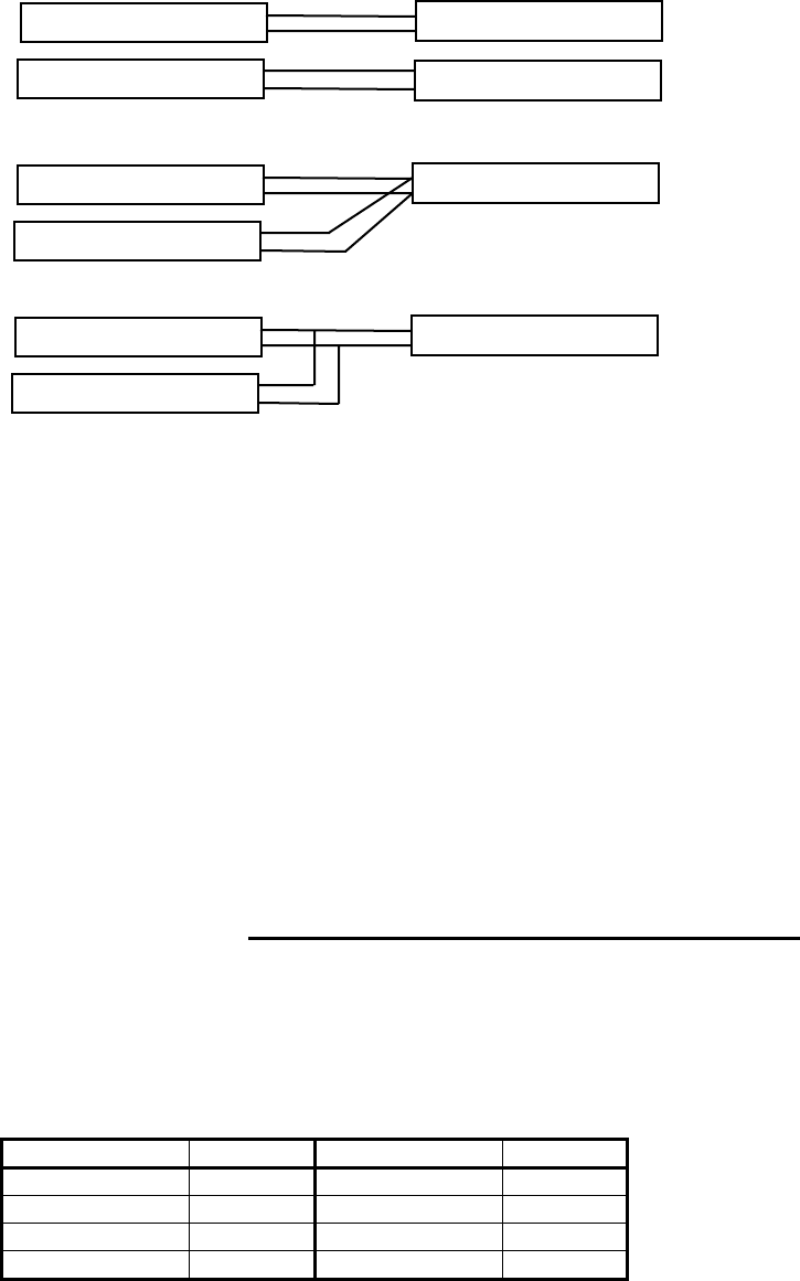
(2) Laying Power Supply Cables
Following connections A and B are recommended to reduce conduction noise gener-
ated from radar. Connection C should not be used.
Connection A
(Very Good)
Connection B
(Good)
Connection C
(Bad)
(3) Grounding
All equipment should be firmly grounded at the earth nearest hull with copper plates
or braided wires.
Improvement Procedure for EMI
(1) Confirm grounding on the radar and radio equipment. However, some equipment, on
which grounding is not always necessarily, have a possibility of EMI improving when
taking off their grounding. Try to take off grounding.
(2) Confirm power supply cable connections and modify to the connection A or B above.
(3) Try to shift the display unit and inter-unit connection cable of radar to be apart from
radio equipment.
(4) Try to shift the feeder of radio equipment to be apart from each units and the inter-
unit connection cable of radar.
(5) Try to shift the antenna coupler and antenna of radio equipment to be apart from
the scanner unit and inter-unit connection cable of radar.
3.11 When Discarding Your Radar
When discarding your RA40C/41C/42C radar, consult the distributor to get informa-
tion on precautions to be followed. Tab.3-7 below lists the primary component materials of
the RA40C/41C/42C radar for your reference.
Tab.3-7 Component Materials
Scanner unit Material Display unit Material
Radome AES Front panel ABS
Chassis A5052P Rear panel ADC12
Base ADC12 Pedestal ABS+PC
Antenna A5052P
RADAR
RADIO EQUIPMENT
SHIP'S SUPPLY
SHIP'S SUPPLY
RADAR
RADIO EQUIPMENT
SHIP'S SUPPLY
RADAR
RADIO EQUIPMENT
SHIP'S SUPPLY