Koden Electronics RB715A Marine Radar RA41C User Manual 19
Koden Electronics Co., Ltd Marine Radar RA41C 19
Contents
19
79
CHAPTER 6. MAINTENANCE AND INSPECTION
Most of maintenance of this radar should be referred to qualified personnel. If
radar has any problem, contact your dealer and tell us that problem.
There are high voltage circuits inside of this radar.
Do not attempt to open the rear cover of display
unit or disassemble internal parts. When you open
the radome, power must be off.
Even power switch is OFF, this radar is still sup-
plied power inside.
The following table shows the maintenance by user. Please check periodically.
Tab. 6-1 Maintenance
*: Use grease for plastics for RA40C/41C. If you use other type of grease(not for plastics),
it may break antenna
Concerning Consumable
The radar uses consumable as listed below that require periodic replacement.
(1) Magnetron
This part is mounted in the scanner unit. If distant echo images have
become less visible, the magnetron probably may have degraded. In such a
case, replace it. Consult your distributor for replacement of this part.
Period of the replacement : 3000hour(typ.) (500hour guarantee)
(2) LCD back-light
This part is mounted in the display unit. If the display screen is ex-
tremely dark and its illumination cannot be corrected by adjusting bright-
ness, the LCD back-light may be faulty or may have burnt out. In such a
case, replace it. Consult your distributor for replacement of this part.
Period of the replacement : 15000hour(typ.) (1000hour at 0•)
Inspection Interval Inspection Item Method of Inspection and Maintenance
3-6 months Rust and looseness
in scanner unit Check whether the scanner’s fitting bolts are
corroded or less.
Display screen of
LCD display Clean filter and LCD screen surfaces with a
soft and wet cloth.
6-12 months Grease* application
to antenna drive
gear
Apply an even coating of grease* to the entire
surface of the antenna drive gear with a spat-
ula or brush.
Check for contact
of connectors Check whether connectors are contacted
properly. If any connector is improperly con-
tacted or stained, correct it by using a contact
restoring chemical agent or by polishing or
replace with a new one if necessary.
Antenna motor
brush(RA42C) Check the length of brushes. If the length is
under 6mm, change them to new one.
!WARNING
80
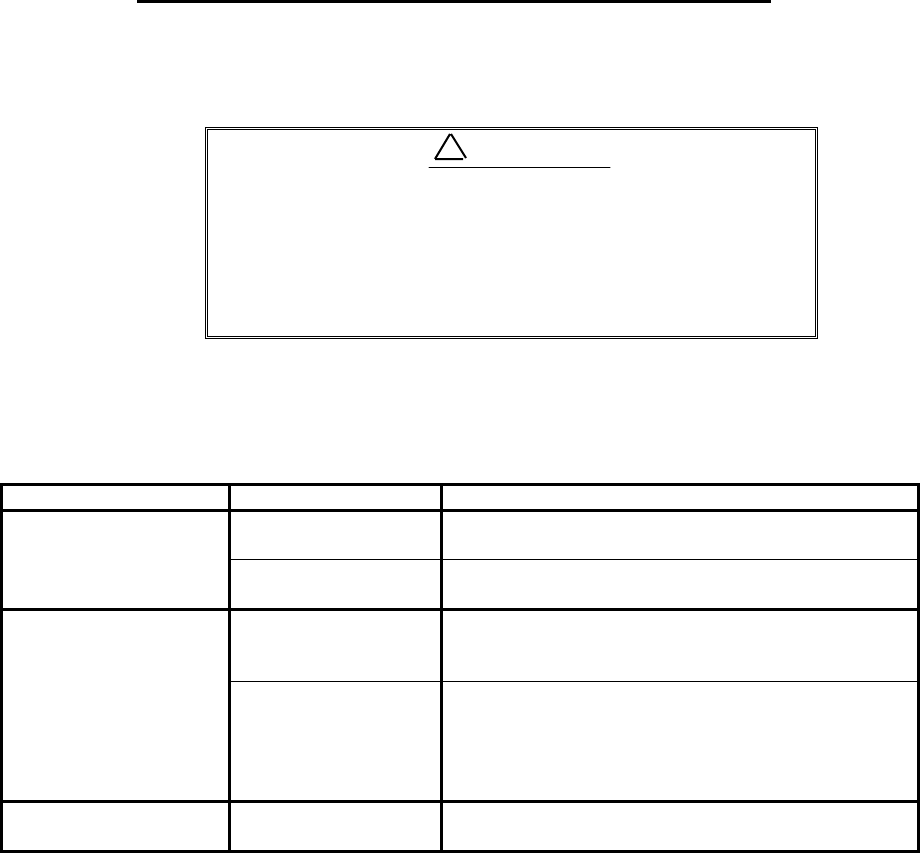
(3) Fuse The fuse is built in
the power supply cable.
If the fuse appears to be
blown, check the fuse. If
blown, replace it
following the procedure
shown in Fig.6-2.
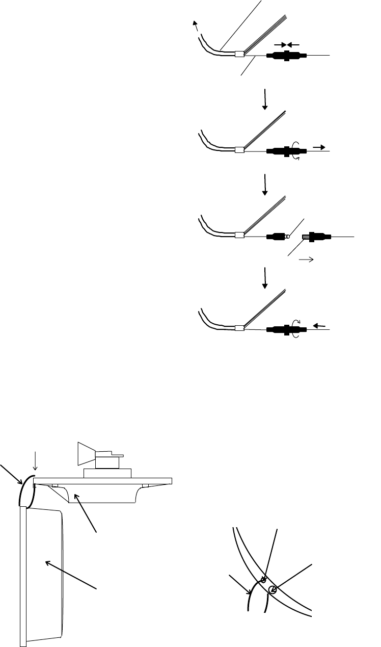
Note: Before maintenance of scanner, you can hang a radome(upper) using cord
through hole as follows.
Fig. 6-3 Method for replacing fuse
Push
Power supply cable
Wire(White)
Turn counterclockwise
and pull
Fuse
Spring
Push and turn clockwise
Replace new fuse
To dis
p
la
y
unit
Fig. 6-2 Method for replacing fuse
Fixing screw
Hole
A: Top view
Cord
Cord
A
Radome(Upper)
Radome(bottom)