Koden Electronics RB715A Marine Radar RA41C User Manual 17
Koden Electronics Co., Ltd Marine Radar RA41C 17
Contents
17
45
5.5 MENU Operation
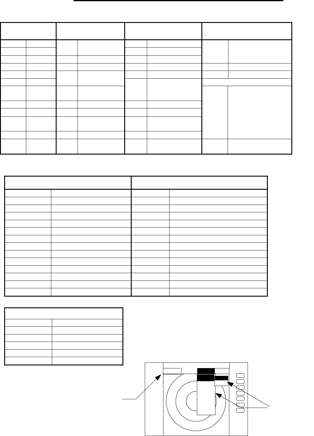
List of MENU
List of Main Menu
MARK
(MAIN-MENU) NAV
(MAIN-MENU) ECHO
(MAIN-MENU) SETUP
(MAIN-MENU)
EBL1 ON/OFF GAIN AUTO/MAN
VRM1 ON/OFF
MODE HU/HS/NU/CU/TM
•MANU/NMEA•STC AUTO/MAN/HARBOR
EBL2 ON/OFF GZ ON/OFF FTC AUTO/MAN
WINDOW PPI/SEMI3D+PPI/
PPI+PPI/PPI+NAV/
ALLPPI/ALL PPI+PPI/MOB
VRM2 ON/OFF OFF-C ON/OFF TUNE AUTO/MAN SEL WIN
FL EBL2 ON/OFF ST OFF/ST1/ST2 PICTURE DAY/NIGHT
FL VRM2 ON/OFF
SLEEP OFF/5min/10min/
15min SYSTEM CHECK
HDG
OFF
OFF
TRACK OFF/15SEC/30SEC/
1MIN/3MIN/6MIN/
CONT
///CSR ON/OFF ZOOM ON/OFF
RINGS ON/OFF SL SHORT/LONG
VAR
RNG
ON/OFF
TARGET
CUSTO
M
KEY ASSIGNMENT
PRESET1 (SUB-MENU)
PRESET2 (SUB-MENU)
ADJUST (SUB-MENU)
+MK
LINE
ON/OFF
List of Custom Menu
PRESET1 (SUB-MENU) PRESET2 (SUB-MENU)
HM FLSH ON/OFF GZ LEVEL 1-7
STERN M ON/OFF GZ MODE IN/OUT
NORTH M ON/OFF HOLD ON/OFF
ST’BY NAVI/NOR DISPLAY RDR/MONI/NAV
BUZ VOL OFF/LOW/HIGH EXT BUZ OFF / CONT / INT
RM UNIT NM / KM / SM IN P/R 1080/1024/2048/4096/360
DEPTH M / FT / FM OUT P/R 1080/1024/2048/4096/360
TEMP °C / F DEMO ON / OFF
EBL BRG REL / TRUE / MAG IR OFF / IR1 / IR2
WP BRG TRUE / MAG SPD SET NMEA / MANU 0.0 KT
HEAD INPUT NMEA / SIN•COS /12BIT / 10BIT LANGUAGE 15 countries
HEAD TRUE / MAG SCAN SPEED STD / HIGH
+MK MODE DIST/BRG•/•LAT/LON
P TABLE 0 - 2
ADJUST (SUB-MENU)
TIMING ADJ
HEAD ADJ
TUNING CAL.
ANTENNA 1-9
GAIN 1-30
STC 1-16
+
ST’BY
.75
. 25
HU
STC >
FTC >
TUNE >
ST >
TRA CK
ZOOM
S/L
MARK NAV ECHO SETUP
ECHO
GAIN > MAN
AUTO
MAIN-MENU
SUB-MENU
46
5.5.1 Mark Menu xxx •keys to press
Setting for markers and cursors
•Common operations for the MARK menu
(Up to the point when "MARK" menu is selected from the main menu)
Press the "MENU" key and select "MARK" from the displayed 4 main menus using the left-
right cursor. (The contents of the selected MENU will appear on a pull-down display in
accordance with the movement of the left-right cursor.)
MENU →Left/Right
(Select MARK)
Further explanation about the MARK menu will be conducted on the assumption that this
"common operation for the MARK menu" has already been completed.
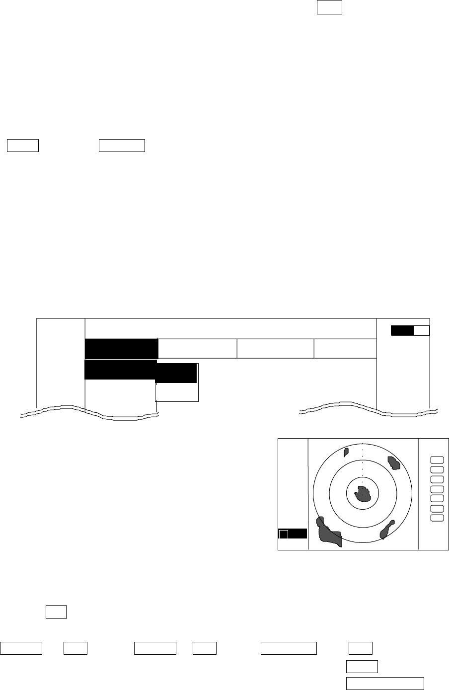
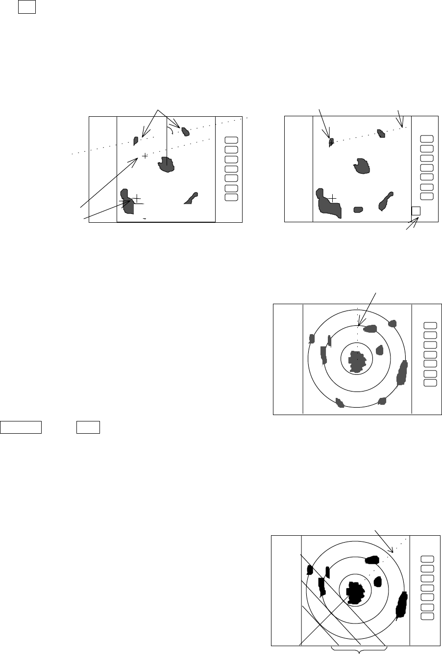
5.5.1.1 Bearing measurement (EBL1)
(1) Select EBL1 from the pull-down display items using the up-down cursor key, and press the
"ENT" key.
(2) When the ON/OFF sign is displayed beside the EBL1 item, select ON with the up-down cursor
keys and press the "ENT" key.
(3) When the "ENT" key is pressed, electric bearing line
(EBL1) appears and the angle from the direction of
the ship’s head which is set at 0 degree will appear
in a reverse display at the lower left of the screen.
(4) Place the marker on the center of the target with the
control knob and read the bearing. Then, the
display setting for EBL1 will be completed either
(a)with the EBL1 display still on the screen if the
"ENT" key is pressed, or (b)without the EBL1
display if the "MENU" key is pressed. (c)Pressing
another function key will lead to the function of
that key with the EBL1 display still on the screen.
Note:• 1 xxx•xφindicates EBL1.
Up/Down → ENT →Up/Down → ENT →Control knob → ENT (a)
(Select EBL1) (Select ON) (EBL1 operation) µ>MENU (b)
µ> Other function key (c)
Note: The displayed EBL angle is relative to heading or true to north, depends on the setting
of "EBL BRG" in the "SETUP" menu.
MARK
EBL1
>
VRM1 >
EBL1 >
.75
.25
HU NAV ECHO SETUP
MARK
>>>
0.23NM
A
. 75
.25
HU
+
1 0.0°
OFF
ON
47
5.5.1.2 Determining the distance (VRM1)
(1) Select VRM1 from the pull-down display items using
the up-down cursor key, and press either the "ENT"
key.
(2) When the ON/OFF sign is displayed beside the
VRM1 item, select ON with the up-down cursor
keys and press the "ENT" key.
(3) When the "ENT" key is pressed, the variable range
marker1 (VRM1) and the distance in a reverse
display appears at the lower left of the screen (See
Note), and the display is set for VRM1.
(4) Place the marker on the front edge of the target with
the control knob and read the distance. Then, the
display setting for VRM1 will be completed either
(a)with the VRM1 display still on the screen if the
"ENT" key is pressed, or (b)without the VRM1
display if the "MENU" key is pressed. (c)Pressing
another function key will lead to the function of
that key with the VRM1 display still on the screen.
Up/Down →ENT →Up/Down →• ENT •→Control knob → ENT
(a)
(Select VRM1) (Select ON) (VRM1 operation) µ>
MENU (b)
µ>Other function key
(c)
Note: 1 xx.xx NM indicates VRM1.
5.5.1.3 Bearing measurement (EBL2)
Refer to the section “Bearing measurement (EBL1)”.
The "EBL2" will appear in a reverse display at the lower right of the screen.
Note:• 2 xxx.xφindicates EBL2.
5.5.1.4 Determining the distance (VRM2)
Refer to the section “Determining the distance (VRM1)”.
The "VRM2" will appear in a reverse display at the lower right of the screen.
Note: 2 xx.xx NM indicates VRM2.
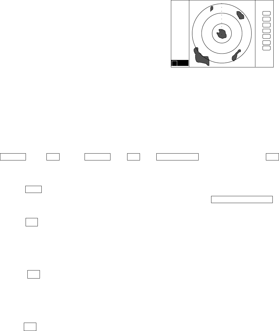
5.5.1.5 Measuring the distance or angle between two points ( FL EBL2, FL VRM2 )
Determining the distance (VRM2)
(a) Preparation for the measurement
(1) Use the up-down cursor keys to select FL VRM2 from among the pull-down display items,
and press the "ENT" key.
(2) Use the up-down cursor keys to select ON from the ON/OFF display beside the FL VRM2
items, and press the "ENT" key. “SET START POINT” is displayed and a small cross mark
.75
.25
HU
+
1 0.00NM
48
appears. (Once this is set, the "ON" state continues unless changes are made.)
Up/Down → ENT → Up/Down → ENT --------------------------------FL VRM2 is turned ON and
(Select FL VRM2) (Select ON) the small cross mark appears.
(b) Setting a reference point for measurement of the distance
Use the left-right and up-down cursor keys to place the small cross mark on one of the two
echoes whose distance will be measured, and press the "ENT" key.
Up/Down & Left/Right →--------------------------- ENT Criterion of the reference point is set.
(Place the cross cursor on an echo)
(c) Measuring
Perform the operations in the above mentioned "Common operation for the MARK menu"
and "measuring the distance(VRM2)", and place the VRM2 on another echo.
VRM2 is displayed on the screen around the placed fixed cross cursor.
" 2 xx. xNM" which is displayed at the lower right will be the distance between the two
points.
Note: EBL2 and VRM2 are not follow to "ZOOM" and "OFF-C" function.
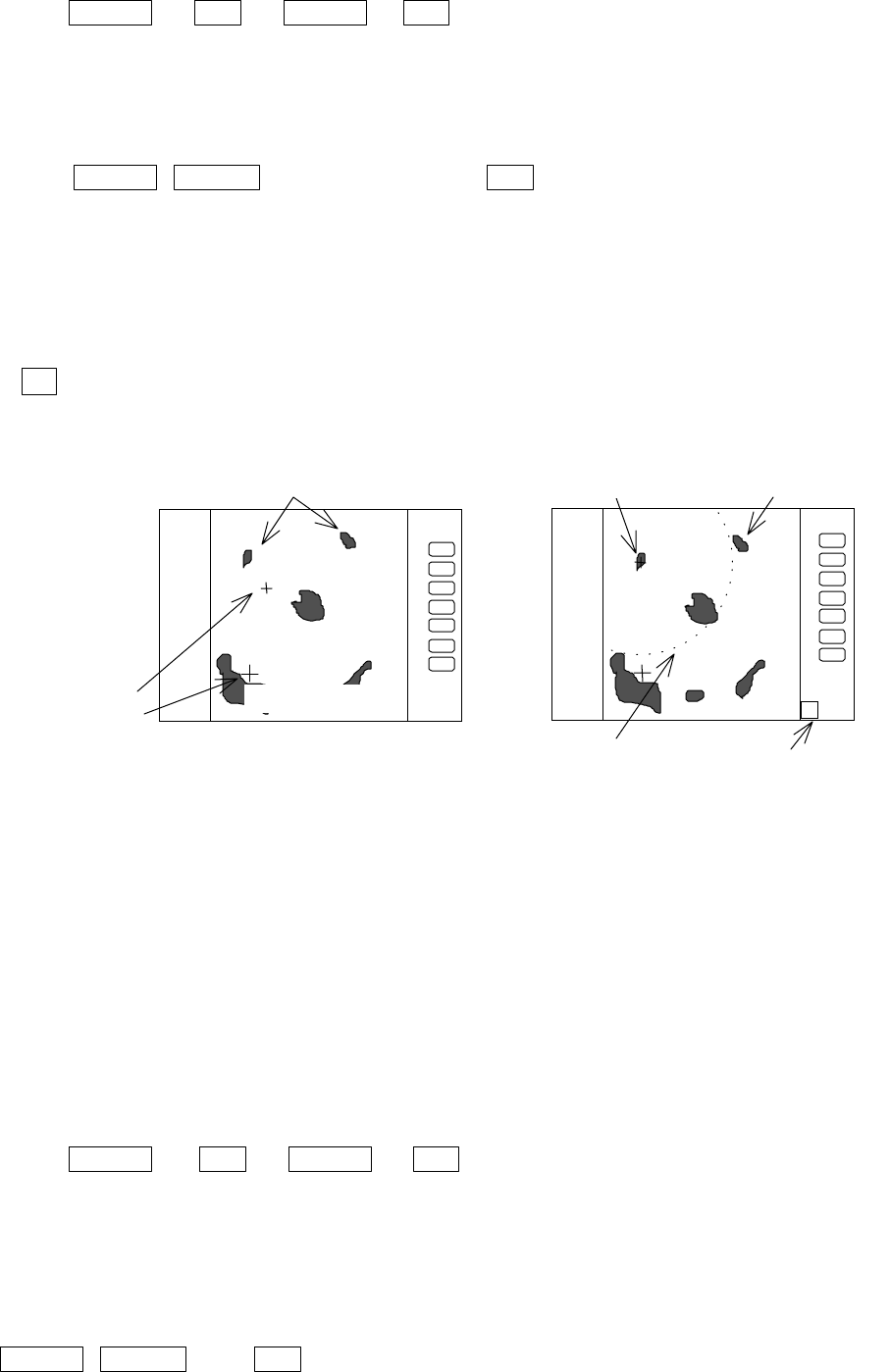
5.5.1.6 Measuring the angle between two points (FL EBL2)
(a) Preparation for the measurement
(1) Use the up-down cursor keys to select FL EBL2 from among the pull-down display items,
and press the "ENT" key.
(2) Use the up-down cursor keys to select ON from the ON/OFF display beside the FL EBL2
items, and press the "ENT" key. “SET START POINT” is displayed and a small cross mark
appears. (Once this is set, the "ON" state continues unless changes are made.)
Up/Down → ENT → Up/Down → ENT --------------------------------FL EBL2 is turned ON and
(Select FL EBL2) (Select ON) the small cross mark appears.
(b) Setting a reference point for measurement of the angle.
Use the left-right and up-down cursor keys to place the small cross mark on one of the two
echoes whose angle will be measured, and press the "ENT" key.
Up/Down & Left/Right → ENT --- Criterion of the reference point is set.
(Place the cross cursor on an echo)
.75
.25
HU
2•0.72NM
place the VRM2
on another
ec
h
o
SET START POINT
.75
.25
HU
measure the
distance between
two targets
small cross
mark
FL VRM2 indication
of VRM2
center of
VRM2
49
(c) Measuring
Perform the operations in the above mentioned "Common operation for the MARK menu"
and "measuring the distance(EBL2)", and place the EBL2 on another echo.
EBL2 is displayed on the screen based on the placed fixed cross cursor.
" 2 xx. xxφ" which is displayed at the lower right will be the angle between the two
points.
Note: The displayed EBL angle is relative to heading or true to north, depends on the setting
of "EBL BRG" in the "SETUP" menu.
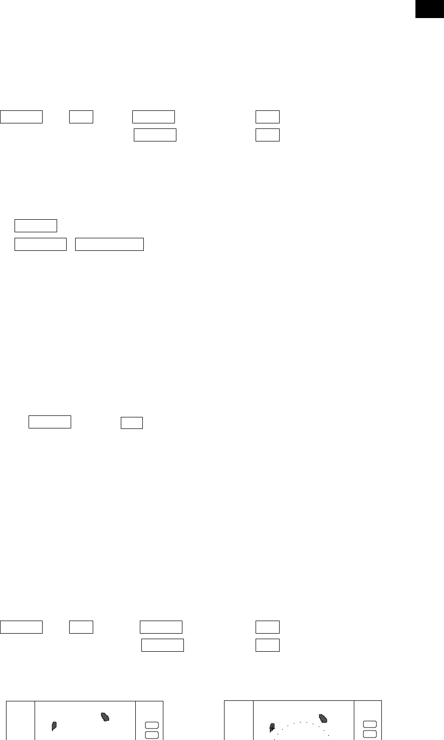
5.5.1.7 Erasing heading marker temporarily (HDG OFF)
(1) Use the up-down cursor key to select HDG OFF
from among the pulled down and displayed items.
(2) Press the “ENT” key. The heading marker is not
displayed as long as you hold it down.
Up/Down → ENT ------------ The heading marker is not displayed as long as you hold “ENT” key down.
(Select HDG OFF)
5.5.1.8 Using parallel cursors (///CSR)
Normally EBL is used to measure the exact bearing from the position of your ship to a
target. However, you can also use parallel cursors.
(1) Use the up-down cursor key to select ///CSR from
among the pull-down and display items, and press the
“ENT” key.(ON/OFF display beside the ///CSR item)
(2) Use the up-down cursor key to select ON .
(3) Press the “ENT” key. Parallel cursors will appear on
the screen. As you move EBL, the parallel cursors also
move.
To cancel the ///CSR function, either select OFF in (2).
.75
.25
HU
.75
.25
HU
Not displayed while ENT
key
ihldd
2•20.•°
FL EBL2
SET START POINT
.75
.25
HU
Origin of
EBL2
measure the angle between
two points
indication
of EBL2
small cross mark
cross mark
.75
.25
HU
EBL1
Parallel•c
50
Up/Down → ENT →Up/Down (Select ON) →ENT -----------------------Parallel cursor appears
(Select ///CSR) µ>Up/Down (Select OFF) →ENT -----------------Parallel cursor non-appears
Note: Interval of ///CSR same as fixed range marker.
///CSR moves with EBL1.
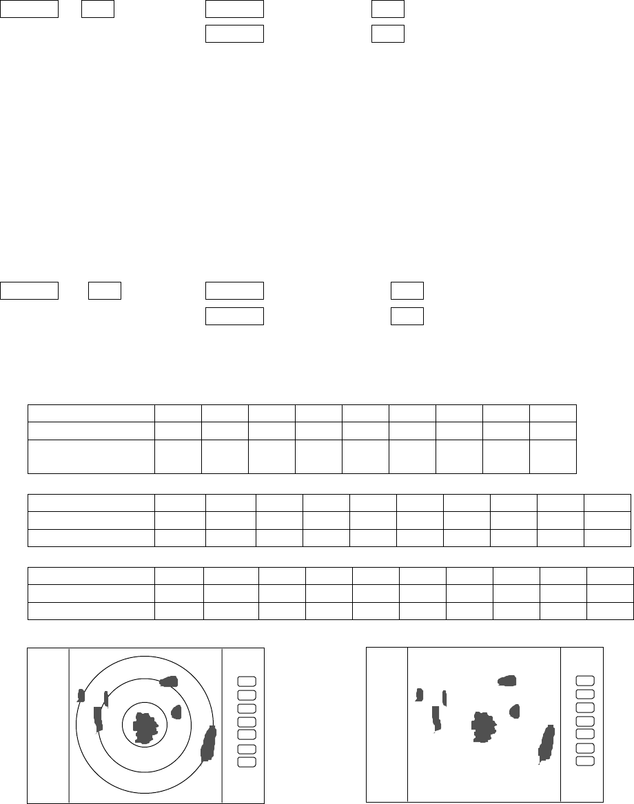
5.5.1.9 Establishment of the indication of the RANGE RINGS (RINGS)
(1) Use the up-down cursor key to select RINGS from among the pull-down and display items, and
press the “ENT” key.(ON/OFF displayed beside the RINGS item)
(2) Use the up-down key to select ON or OFF and press the “ENT” key
Select ON Range Rings ON
Select OFF Range rings OFF
Up/Down → ENT --→Up/Down (Select ON) →ENT -----------------Range rings appears
(Select RINGS) µ>Up/Down (Select OFF) →ENT -----------Range rings non-appears
•Number of range rings and range interval
•Radome antenna (RA40C)
Range 0.125 •0.25 0.5 0.75 1.5 3 6 12 24
Number of Rings222366666
Interval 0.062
5
0.125 0.25 0.25 0.25 0.5 1 2 4
Radome antenna (RA41C)
Range 0.125 0.25 0.5 0.75 1.5 3 6 12 24 36
Number of Rings 2 2 23666668
Interval 0.0625 0.125 0.25 0.25 0.25 0.5 1244
Open antenna (RA42C)
Range 0.125 0.25 0.5 0.75 1.5 3 6 12 24 48
Number of Rings 2 2 23666668
Interval 0.0625 0.125 0.25 0.25 0.25 0.5 1246
5.5.1.10 Variable range function ( VAR RNG )
Usually the range changes in steps as 0.5--0.75--1.5--3.0--....., but using this function will
enable a consecutive change such as 0.5--0.6--0.7--0.8--..... .
(1) Use the up-down cursor keys to select VAR RNG from among the pulled down and displayed
.75
.25
HU
.75
.25
HU
Range rings Range rings OFF
51
items, and press the "ENT" key.
(2) When ON is selected with the up-down cursor key from the ON/OFF display beside the VAR
RNG item, and the "ENT" key is pressed, the VAR RNG function becomes valid and VAR will
be displayed at the upper left of the screen (beside MODE).
Setting procedure
Up/Down → ENT → Up/Down (Select ON) → ENT VAR RNG function is turned ON
(Select VAR RNG) µ> Up/Down (Select OFF) → ENT VAR RNG function is turned OFF
(3) The range changes continuously with pressing the up-down cursor while the VAR RNG
function is on, and it changes in steps with the "RANGE UP" or "RANGE DOWN" keys.
Method of use
Up/Down ------------------------------------------- Range changes continuously
RANGE UP & RANGE DOWN -------------- Range changes in step
(4) To cancel the vari-range function, press a key except "RANGE UP" and "RANGE DOWN" key.
When use the function, follow from (1) again.
5.5.1.11 Output the position data of Cursor ( TARGET )
Place the cross cursor to the position that is to output position data with up-down and left-
right key.
Use the up-down cursor keys to select TARGET from among the pull-down display items, and
press the "ENT" key. The L/L data of the position will be output to NMEA port with TLL format.
Up/Down →••• •............................................ output the L/L position of the cursor
(Select TARGET)
Note: When activate this function, nothing happens on the screen.
5.5.1.12 Follow the Distance and Bearing marker on the cursor (+MK LINE)
(1) Use the up-down cursor keys to select +MK LINE from among the pulled down and displayed
items, and press the "ENT" key.
(2) When ON is selected with the up-down cursor key from the ON/OFF display beside the +MK
LINE item, and the "ENT" key is pressed, the +MK LINE function becomes valid, and
distance/bearing marker will be displayed at the cross cursor.
Setting procedure
Up/Down → ENT → Up/Down (Select ON) → ENT +MK LINE function is turned ON
(Select +MK LINE) µ> Up/Down (Select OFF) → ENT +MK LINE function is turned OFF
(3) The distance/bearing marker follows to the cross cursor until +MK LINE function is turned
OFF.
.75
.25
HU
.75
.25
HU
52