Koden Electronics RB715A Marine Radar RA41C User Manual 18
Koden Electronics Co., Ltd Marine Radar RA41C 18
Contents
18
25
CHAPTER 4. FUNCTIONS AND NAMES
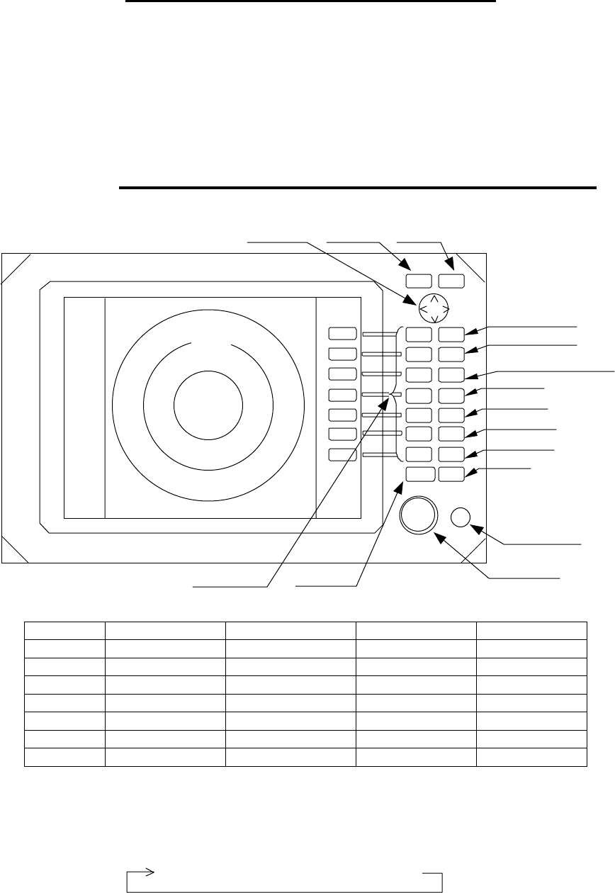
Function and name of each part
The RA40C/41C/42C radar consists of a display unit to display video images on a
screen and a scanner unit configured with an antenna to radiate radio waves and other
components. The display unit has on its front panel eighteen(18) push-switch keys and
one cursor key that lets you move a cursor in any desired direction. A combination of
these keys allows you to utilize all functions of your radar, providing a comfortable, easy
way to operate.
4.1 Key layout
Key No. SET1 SET2 SET3 SET4
1 EBL1 EBL2 RINGS PPI
2 VRM1 VRM2 TUNE PPI/3D
3 VAR RNG FL EBL2 ST PPI/PPI
4 TRACK FL VRM2 ZOOM PPI/NAV
5 TARGET GZ SLEEP ALL PPI
6 SEL WIN OFF-C PICTURE ALL PPI2
7 NEXT NEXT NEXT NEXT
Tab. 5 Function of soft key (Factory setting)
*Every time Next key is pressed, soft key group switches as follows.
Cursor ke
y
MENU ke
y
ENT ke
y
3
1
HU s RANGE
UP
RANGE
DOWN
BRILL
AUTO
GAIN
STC
FTC
MOB
1
2
3
4
5
6
7
POWER
ENT
MENU
MOTOR
1:58
+
POWER key
Soft ke
y
s(* )
RADAR OFF
Scanner
Motor fuse
Control knob
RANGE Up key
RANGE Down key
BRILL key( Contrast
Brilliance, keys backlight)
AUTO key
GAIN key
STC key
FTC key
MOB key
SET1 → SET2
→ SET3
→ SET4
26
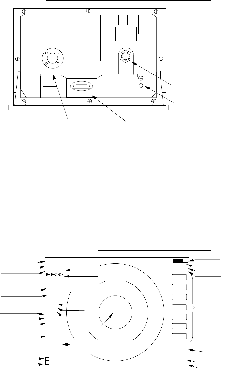
4.2 Rear panel
!
!!
! Power supply connector
Use this connector to plug in the power supply cable. Standard NMEA interface
terminal is included in this connector. Refer to Section 3.7 “ Connecting Cables “
and Section 3.9 “Connecting External Equipment to Display Unit “.
"
""
" Grounding terminal
Use this terminal to connect grounding wire. Refer to Section 3.7 (3) “Grounding
wire”.
#
##
# Option connector
Use this connector to connect NMEA, an external monitor, external buzzer and
GYRO I/F. A dedicated cable or dedicated module box is required to connect these
pieces of equipment. Refer to Section 3.9 “Connecting External Equipment to
Display Unit”.
$
$$
$ Scanner connector
Use this connector to plug in the inter-connecting cable to connect the scanner
unit.
Refer to 3.7 “Connecting cable “.
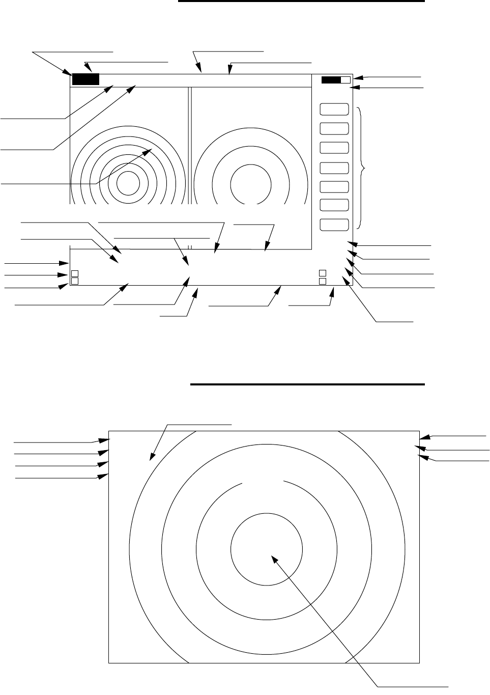
4.3 Radar screen•Single screen•
SCANNER POWER
OPTION
Ship’s position
EBL2
VRM2
Indicate soft key
3
1
HU L
1:58
+
RADAR OFF
EBL1
VRM1
EBL2
VRM2
FL EBL2
FL VRM2
NEXT
A
HOLD
ZOOM
OFF-C
LAT/LON
35°08 D
42N
139°02 D
53E
2 129 D
8°
212
D
34NM
0.23NM
HDG
129.0
°T
SPD
12.0 KT
G 59
S AT
F AT
ST1
GZ IN
TK 15 S
WP
134.4 °
12.5NM
+LAT/LON
35°08.42N
139°02.53E
1 129.8°
1 12.3NM
Tune meter
Picture hold
Zoom
Off-center
Range
Range ring interval
Display mode
Heading angle
Cruising speed
Enlarging echo
Guard zone
Track
Way point
EBL1
VRM1
Pulse width
Course error
Gain
STC
FTC
Cross cursor
Cross cursor position
(LAT/LON or Distance/Bearing j
!Power supply connector
"Grounding terminal
$Scanner connector #Option connector
27
4.4 Radar screen (Dual screen)
ex) PPI/PPI screen
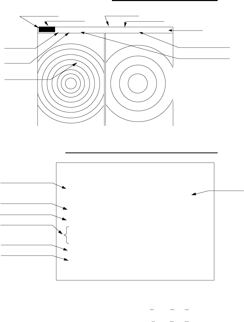
4.5 Radar screen (All PPI screen)
Tune meter
Picture hold
Indicate soft key
SPD 12.8KT GZ R IN WAY P 134.4°
HDG 129.2° GZ L IN 12.5NM
+MK 38.4° ST1 LAT 35°08.42N 2 129.8 ‹
5.28 TK 15S LON 139°02.53 ‚d
2 3.62NM
6 1.0_ HU L .75
.25
EBL1
VRM1
EBL2
VRM2
FL EBL2
FL VRM2
NEXT
A
HOLD
0.23
XTE >>>
1 129.8°
1 12.34NM
AT1
G 59 / AT
S AT / AT
F AT / AT
Range(Left screen) Range(Right screen)
Range ring interval Range ring interval
(Left screen) (Right screen)
Display mode
Pulse width
Cross cursor
Course error
EBL1
VRM1
+
Cruising speed Guard zone(Right screen) Way point
Heading angle Guard zone(Left screen)
Cross coursor position Enlarging echo Ship’s position VRM2
(LAT/LON or Distance/Bearing) Track EBL2
AUTO (Left/Right)
Gain (Left/Right)
STC (Left/Right)
FTC (Left/Right)
3
1
HU L
GZ IN 1:58
+
RADAR OFF
OFF-C
HOLD
ZOOM
Off-center
Picture hold
Zoom
Range
Range ring interval
Display mode
Guard Zone
Pulse width
Cross cursor
28
4.6 Radar screen (All PPI /PPI screen)
4.7 Navigation screen
It is necessary that navigation equipment such as a GPS is connected to your
radar, this screen displays the position and cruising speed of your ship, seawater
temperature, and other navigation information.
Note: Heading angle will be displayed "COG" when Course Over Ground data is
used.
Note: Cruising speed will be displayed "SOG" when Speed Over Ground data is
used.
Picture hold
Gurad zone(Right screen)
Guard zone(Left screen)
6 1.0_ HU L GZ IN .75
.25 GZ IN HOLD
Range(Left screen) Range(Right screen)
Range ring interval Range ring interval
(Left screen) (Right screen)
+
Display mode
Pulse width
Cross cursor
NAV DISPLAY
WP 134.4°
°°
°COURSE
12.5NM >>>
HDG 129.0°
°°
°0.23NM
SPD 12.8KT
LAT 35°
°°
°08.42N
LON 139.02.53E
TEMP 20.5°
°°
°C
DEPTH 93.2MST’BY
Way point
Heading angle
Cruising speed
Current position
Sea water temperature
Depth of water
Course error
@@
(XTE)
29
> Indicates starboarding the helm
(right)
< Indicates porting the helm (left)
Deviation from course Indication mark
0.00 -- ><
0.02 -- > or <
0.04 -- >> or <<
0.08 -- >>> or <<<
0.16 -- >>>> or <<<<
Tab.6 Indication of deviation from course