Koden Electronics RB716A Marine Radar RA42C User Manual 14
Koden Electronics Co., Ltd Marine Radar RA42C 14
Contents
14
75
5.5.4.5.4 Changing the content of settings (ADJUST)
The items in the ADJUST menu are ones that need adjustment at the time of installation.
The settings need not normally be altered.
(1) Adjusting distance (TIMING ADJ)
This adjustment is necessary to adjust the distance on the radar screen to the actual
distance.
(1) In preparation for adjusting the distance, the following adjustments are to be conducted.
First, set the radar range to 0.25 NM, FTC to minimum, and GAIN to optimum. Then
adjust STC until the pulse generated by your own radar appearing at the center of the
screen is clearly recognized as a round dot.
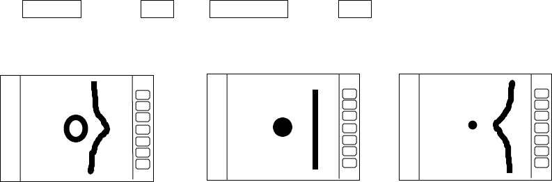
(2) Adjusting the distance.
(2)-1 Select ADJUST by "common operations for CUSTOM", use up-down cursor keys to
select TIMING ADJ from among the pull-down display items and press the "ENT" key.
(2)-2 As the distance adjustment screen is displayed, adjust timing until the center dot
looks as (b) with the control knob. If there is a linear target such as a bridge or
breakwater, adjust timing until the target appears straight in the screen.
(2)-3 When the adjustment is finished, press the "ENT" key to exit from the distance
adjustment screen.
Up/Down →ENT →Control knob →ENT
select TIMIG ADJ •Timing adjustment finished
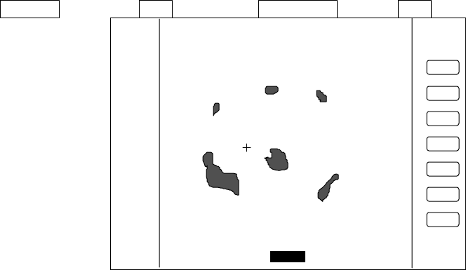
(2) Adjusting angle (HEAD ADJ)
This adjustment is necessary to adjust the head direction on the screen to the actual
direction of the ship.
Note: Heading offset value for open antenna is different from that for a radome antenna.
(1) In preparation for adjusting the angle, the following adjustments are to be conducted.
(1)-1 Find one small target within a 0.5 to 1.5 NM range which, lying in the bow direction,
can be detected with eyes and is clearly visible in the radar screen.
(1)-2 Measure the bearing of this target from the bow direction using a compass. Let it be•c.
(1)-3 Measure the bearing of the above target in head up (HU) mode using EBL. Let it be•r.
(1)-4 Calculate the following:
•c - •r• if•c is greater than •r
a) Too far b) Correct c) Too shrunk
76
360 - ( •r - •c ) • if•r is greater than •c
This is the azimuth error of your radar at installation. If •c and •r are equal, the
adjustment described below is unnecessary.
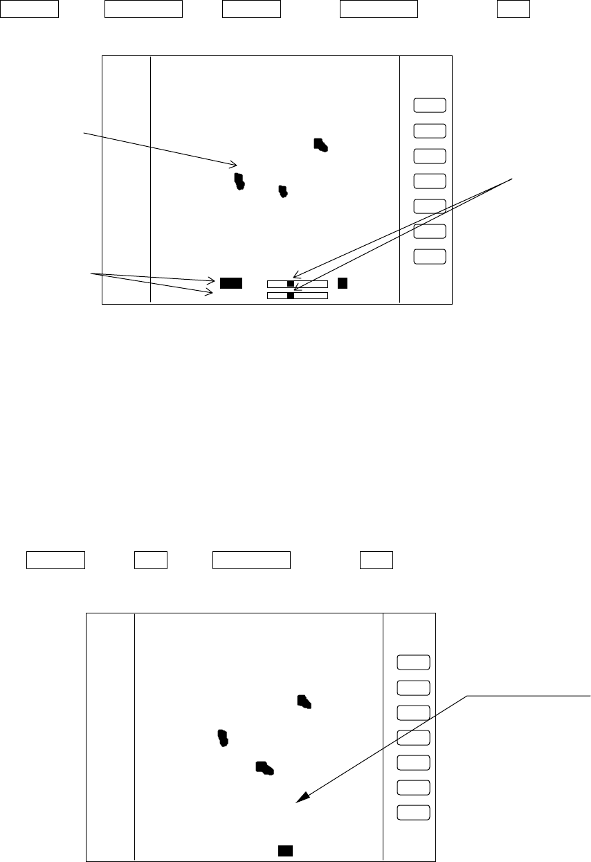
(2) Adjustment method
(2)-1 Select ADJUST by "common operations for CUSTOM", use the up-down cursor keys
to select HEAD ADJ from among the pull-down display items and press the "ENT"
key.
(2)-2 As the distance adjustment screen is displayed, set the value to the azimuth error
you have calculated above with the control knob.
(2)-3 When the adjustment is finished, press the "ENT" key to exit from the distance
adjustment screen.
Up/Down →ENT →Control knob →ENT
Select HEAD ADJ. Set a value to .
(3) Adjusting tuning circuit (TUNING CAL)
Normally you do not need to make this adjustment. This adjustment may necessary to
ensure that the automatic tuning circuit operate at its best operating point. However, if
sensitivity is poor or there is any symptom suggesting improper tuning, you may need to adjust
this circuit following the procedure below.
(1) Choose several stable video images in the 3 NM range or more.
(2) Select ADJUST by "common operations for CUSTOM", use the up-down cursor keys to
select TUNING CAL. from among the pull-down display items and press the "ENT" key.
(3) As the tuning circuit adjustment screen(TUNING CALIBRATION) is displayed, select AUTO
with up-down cursor key.
(4) While watching video images, adjust until echoes are clearly visible with the control knob.
(5) Select MANUAL with the down cursor key.
HEAD DIRECTION ADJUSTMENT
ADJ UST WITH CONTROL KNOB
PRESS ENTER KEY TO RETURN
_358.8°
°°
°_
HEADING Adjustment
3
1
HU
77
(6) Adjust until echoes are clearly visible with the control knob. This set status is middle
value of manual tuning.
(7) When the adjustment is finished, press the "ENT" key to exit from the TUNING
CALIBRATION screen.
Operate of (3) to (7)
Up/Down →Control knob →Up/Down →Control knob •→ENT
Select AUTO Adjust tuning Select MANU Adjust tuning
(4) Adjusting antenna height (ANTENNA)
Depending on the position at which the antenna is installed, it may be necessary to make
the following correction. (Consult distributor for details.)
(1) Select ADJUST by "common operations for CUSTOM", use the up-down cursor keys to
select ANTENNA from among the pull-down display items and press the "ENT" key.
(2) As the adjustment screen is displayed, using the control knob to choose your desired value
from 1 to 9.
(3) Press the "ENT" key to exit from the adjusting antenna height screen.
Up/Down →ENT →Control knob →ENT
Select ANTENNA Choose value Complete
Adjust with control knob
Select with up-down
cursor key
Echo remain.
TUNING CALIBRATION
READ OPERATION MANUAL
SELECT ITEM WITH •• KEY
TUNE WITH CONTROL KNOB
PRESS ENTER KEY TO MEMORY
AUTO ••••••••
MANUAL ••
3
1
HU
Adjust with Control knob
STC CURV E ADJUSTMENT
ADJ UST WITH CONTROL KNOB
PRESS ENTER KEY TO MEMORY
STC CURV E _5_
3
1
HU
ANTENNA Adjustment

78
(5) Setting GAIN circuit (GAIN)
Here, you set the automatic and manual gain level. Normally, adjust this setting to be
slight the noise echo appears on the screen.•When enter this setting at AUTO mode, you can
preset AUTO GAIN level. When enter at MANUAL mode, you can preset the MANUAL GAIN to
current MANUAL gain level as the standard. When you enter the setting at "G60" of gain level,
for instance, gain level of "G60" is preset as the standard level.
(1) Select ADJUST by "common operations for CUSTOM", use the up-down cursor keys to
select GAIN from among the pull-down display items and press the "ENT" key.
(2) As the adjustment screen is displayed, using the control knob to choose your desired value
from 1 to 30.
(3) Press the "ENT" key to exit from the adjustment screen.
Up/Down →ENT →Control knob →ENT
Select GAIN Choose value Complete
(6) Setting STC circuit (STC)
Here, you set the STC level. Adjust this setting to be slight sea clutter appears on the
screen, when you observe a small target (ex. Small buoy). When enter this setting at AUTO
mode, you can preset AUTO STC level and AUTO FTC level. When enter at HARBOR (HBR)
mode, you can preset HARBOR STC level.
When enter at MANUAL mode, you can preset MANUAL STC level as the standard level.
(1) Select ADJUST by "common operations for CUSTOM", use the up-down cursor keys to
select STC from among the pull-down display items and press the "ENT" key.
(2) As the adjustment screen is displayed, using the control knob to choose your desired value
from 1 to 16.
(3) Press the "ENT" key to exit from the adjustment screen.
Up/Down →ENT →Control knob →ENT
Select STC Choose value Complete