LG Electronics USA 3G1XINBTS STAREX-IS 1900 Indoor BTS User Manual STAREX IS User s Manual
LG Electronics USA STAREX-IS 1900 Indoor BTS STAREX IS User s Manual
UserManual.wiki
>
LG Electronics USA
>
3G1XINBTS User Manual
>
Users Manual Part A
Contents
1.
Users Manual Part A
2.
Users Manual Part B
3.
Users Manual Part C
4.
Users Manual Part D
5.
Users Manual Part E
6.
Users Manual Part F
7.
Users Manual Part G
Users Manual Part A
Navigation menu
Upload a User Manual
Namespaces
Wiki Guide
HTML
PDF
Info
Views
User Manual
Discussion / Help
Navigation
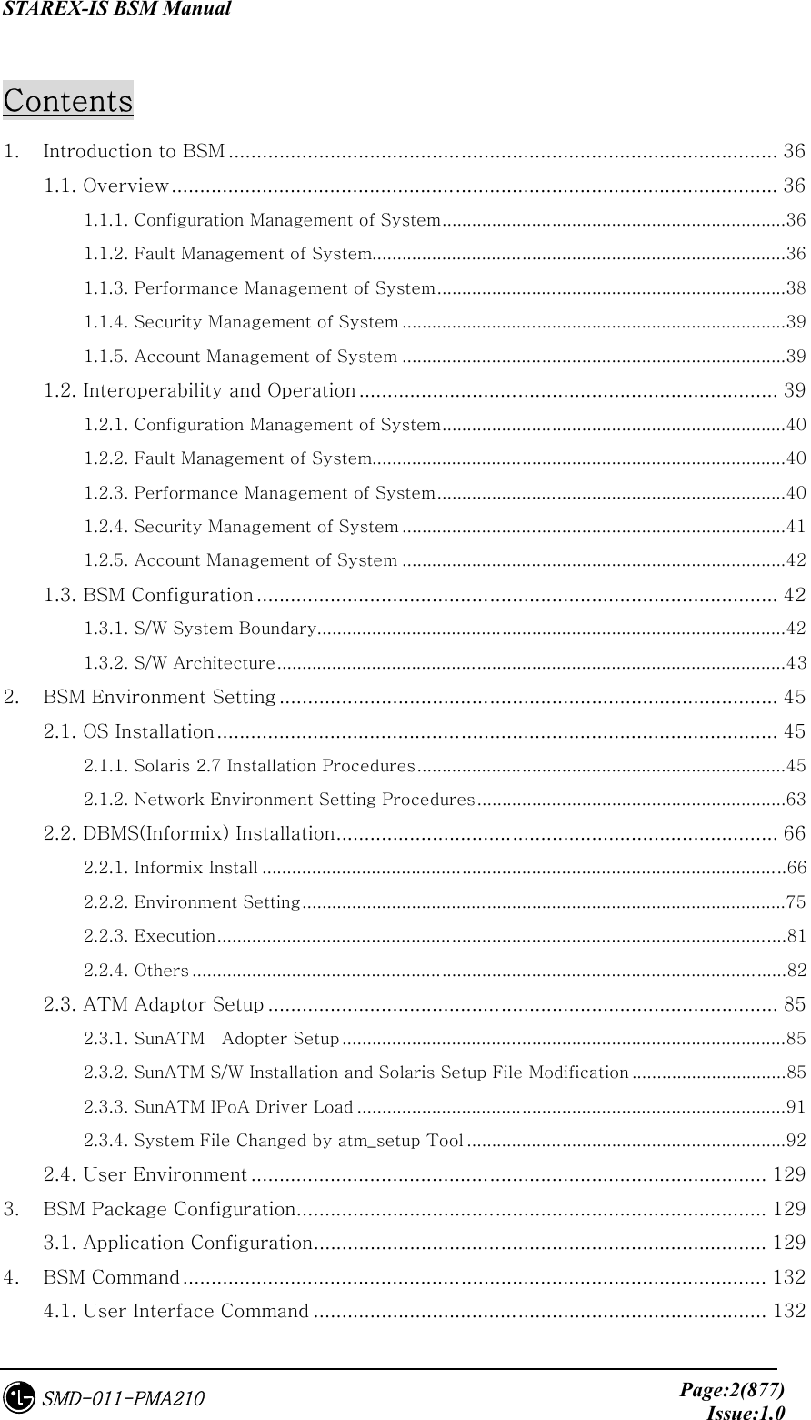
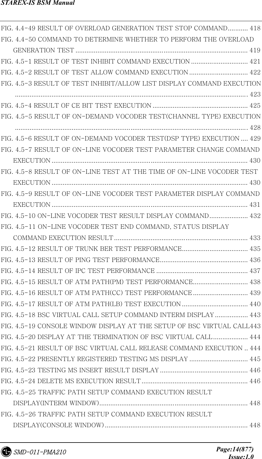
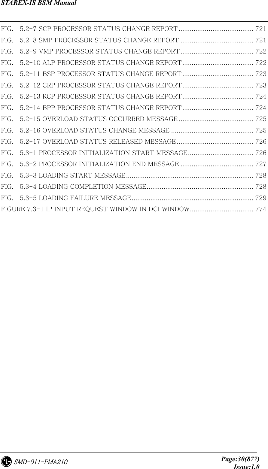
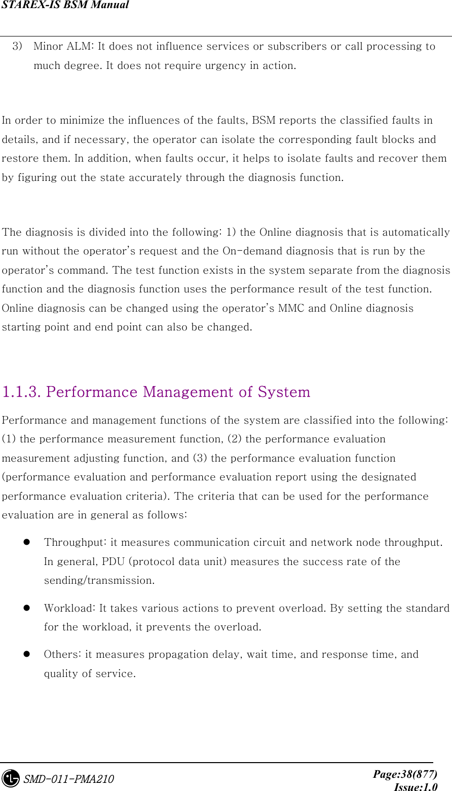
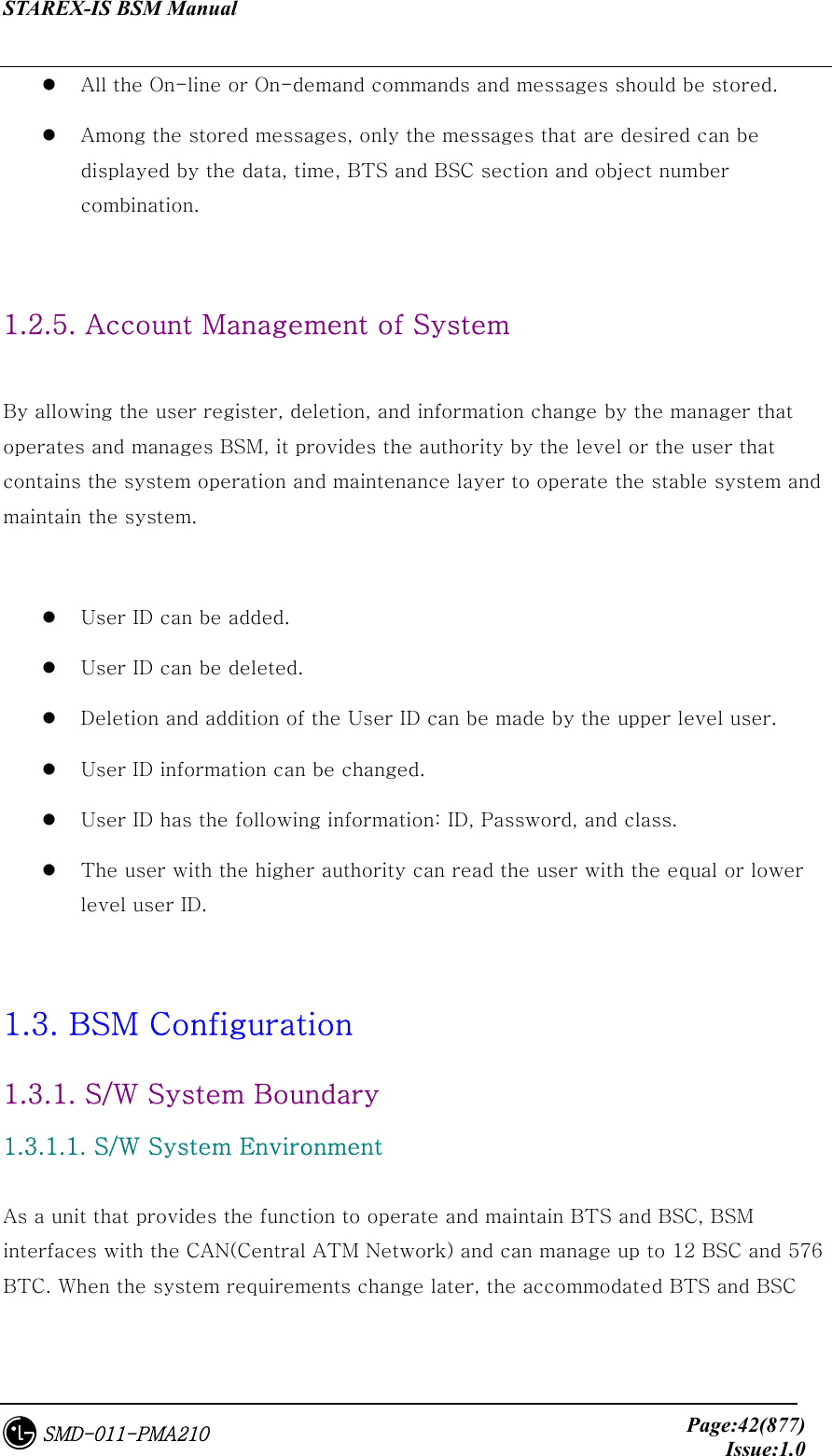
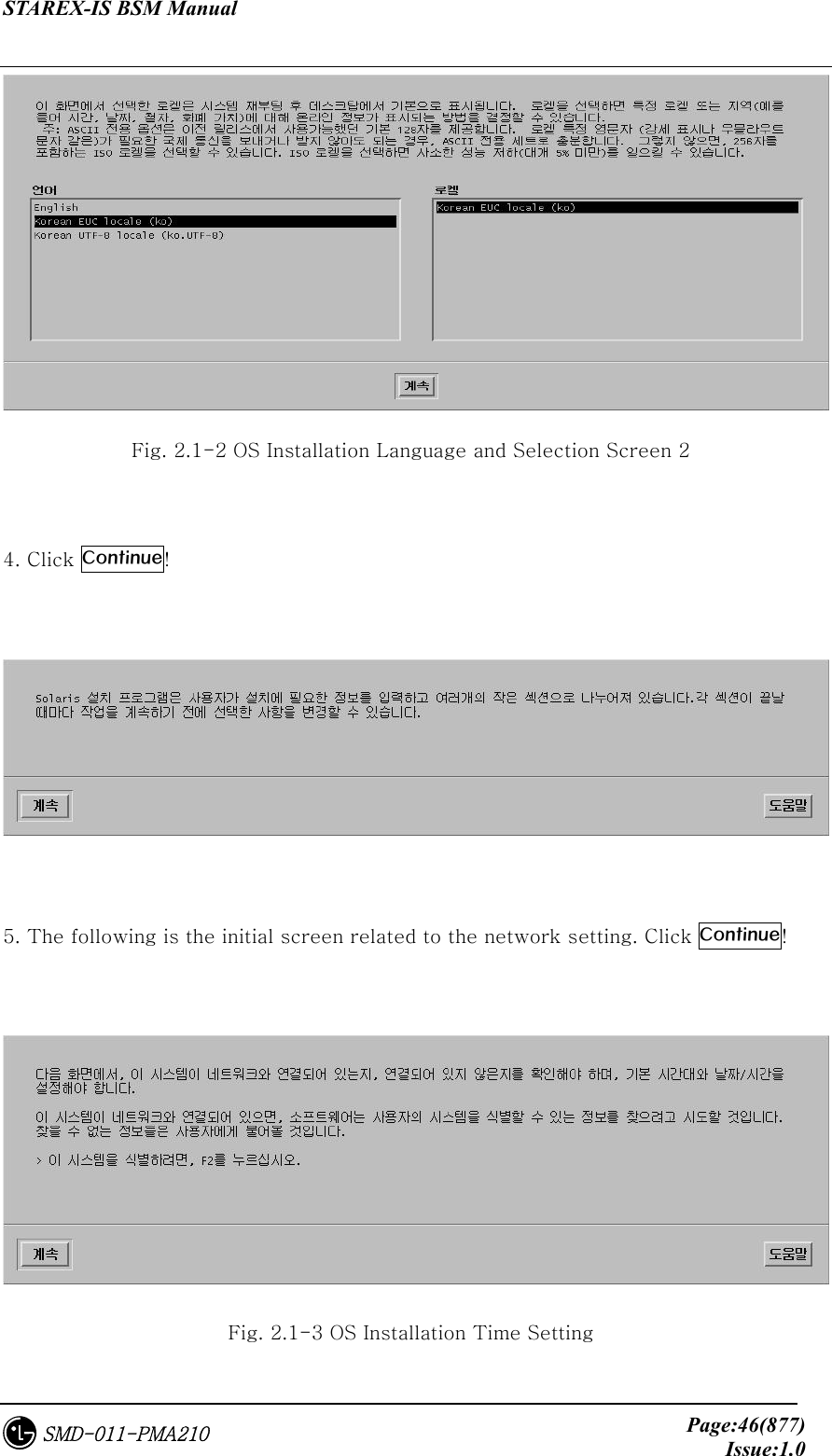
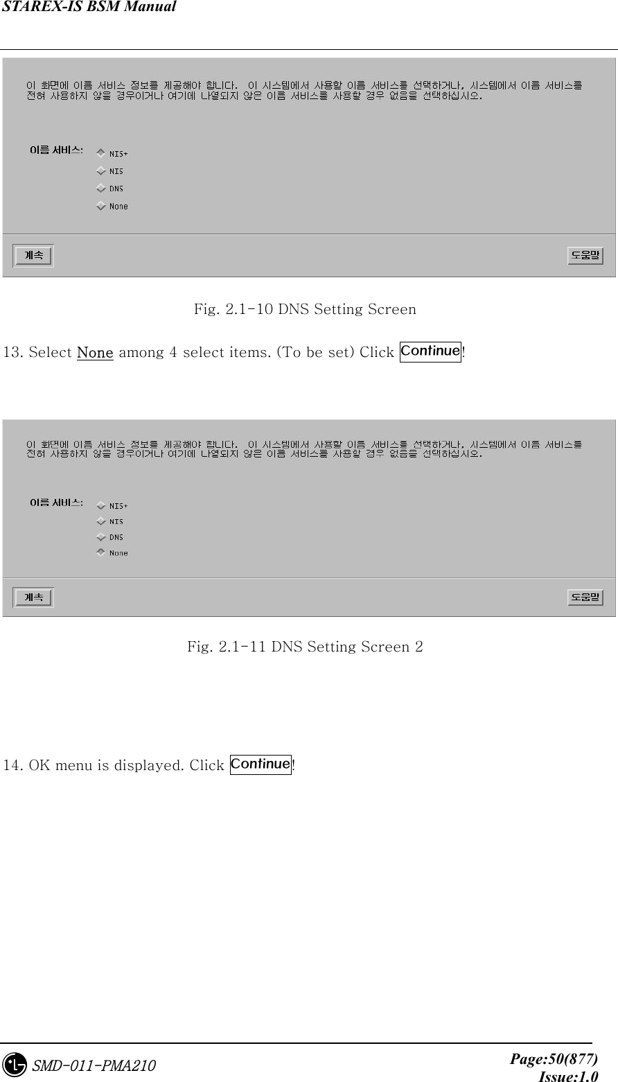
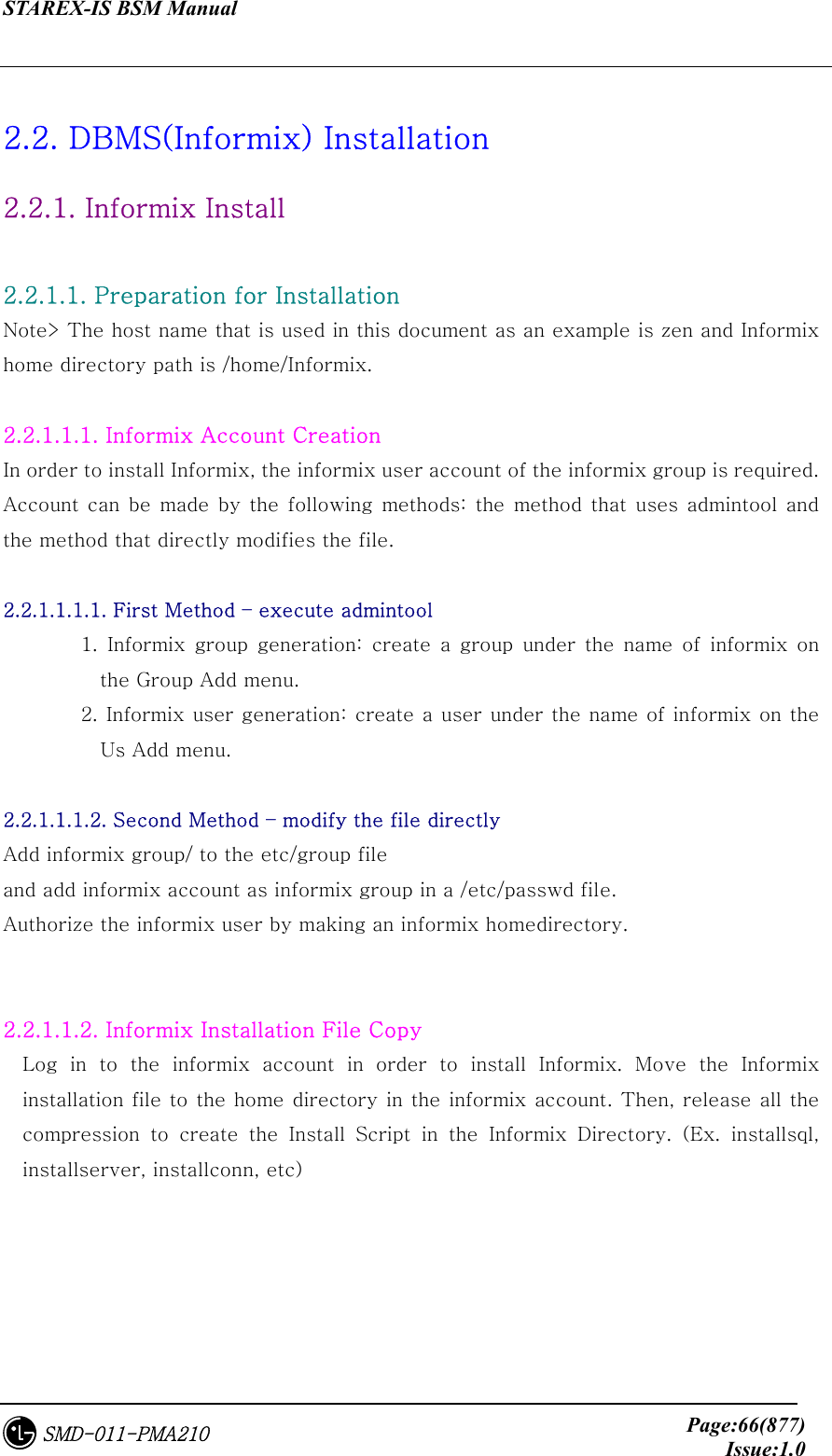
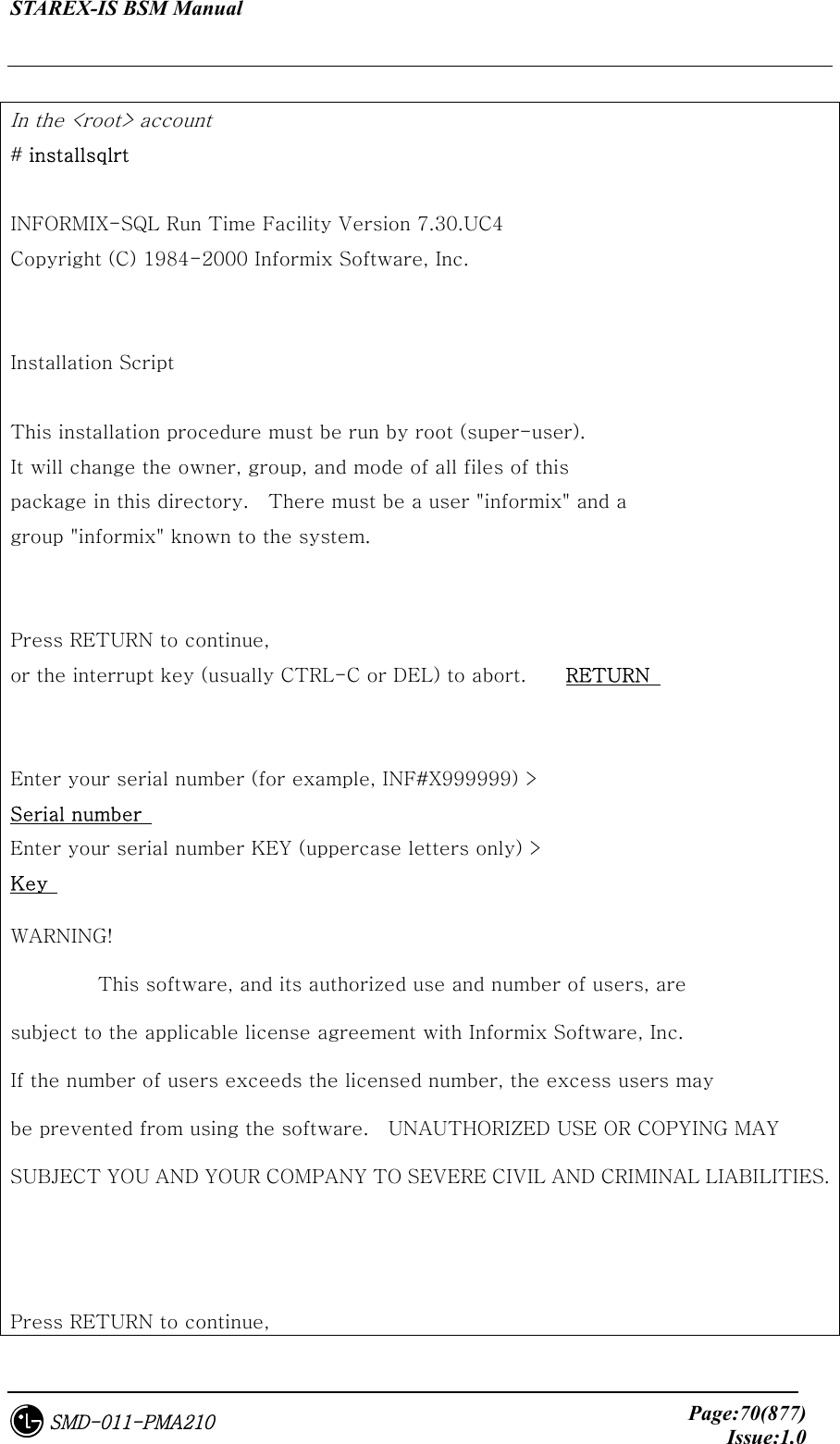
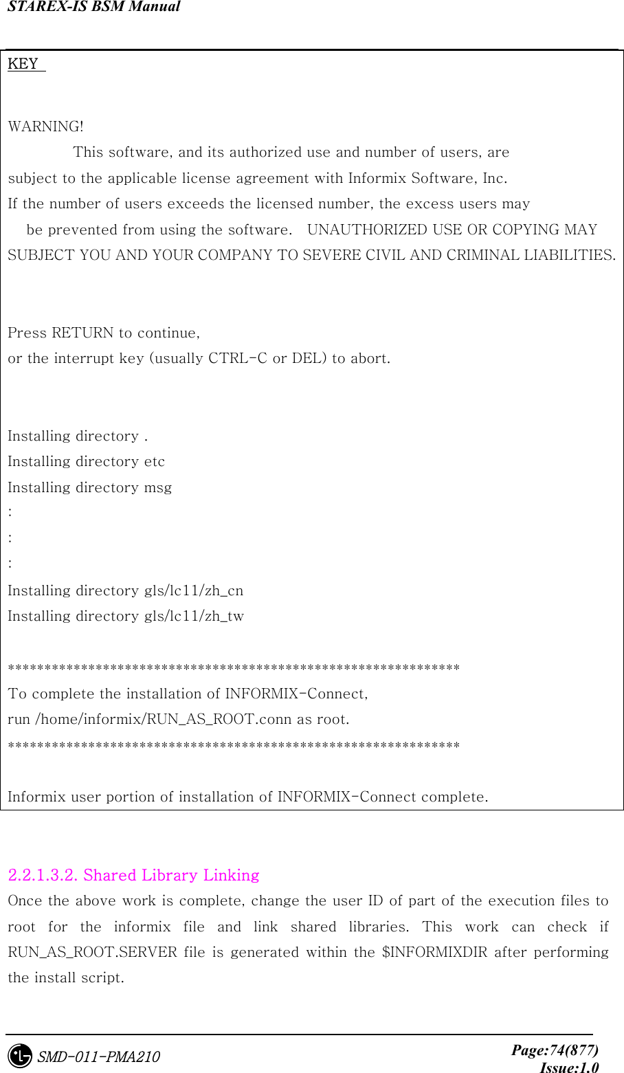
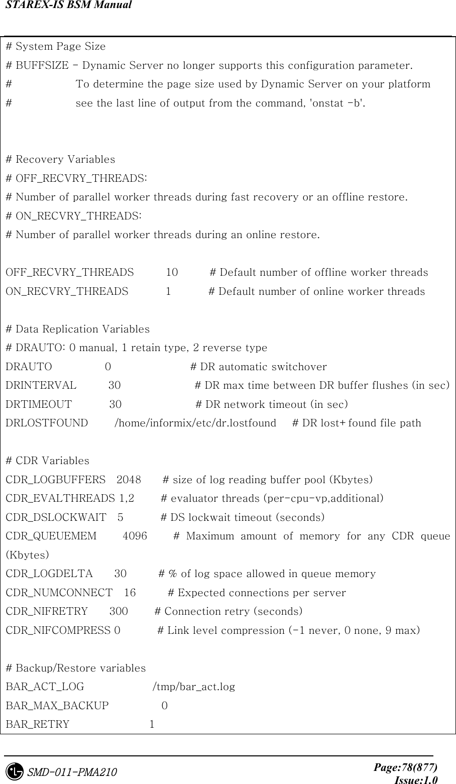
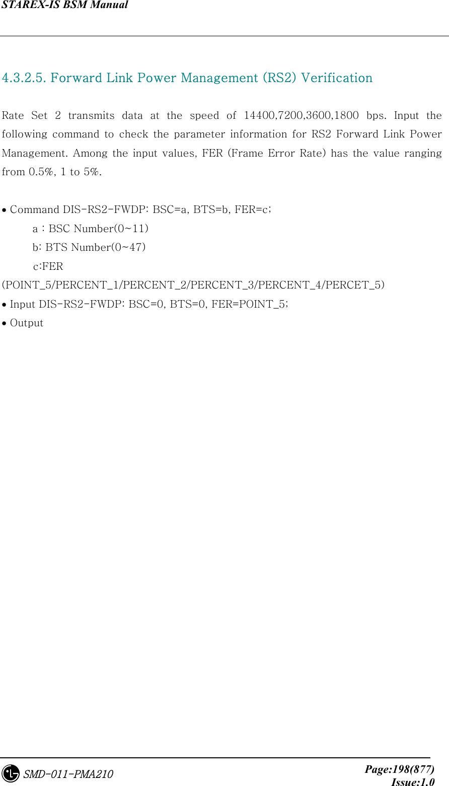
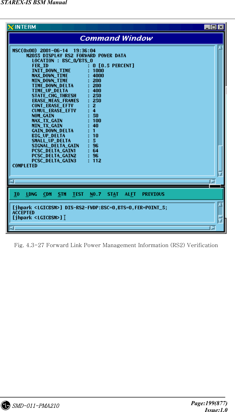
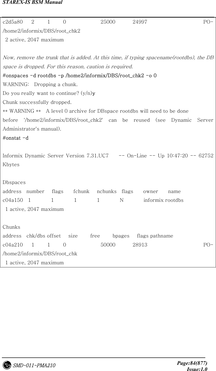
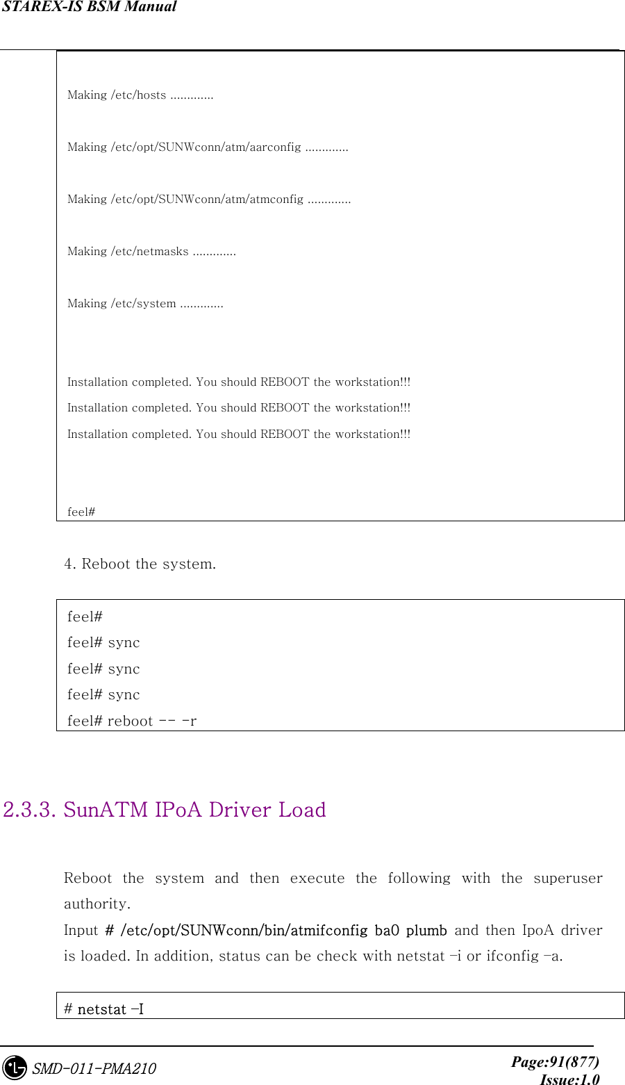
![STAREX-IS BSM Manual Page:82(877)Issue:1.0SMD-011-PMA210 # 2.2.4. Others 2.2.4.1. Command Usage Viewing command -- <= Give – option to the command to see the command usage. 2.2.4.2. DB Space Viewing and Expansion One can see the entire size of the DB and Chunk in use. If the DB space in use is short, it can be expanded by adding chunk. #onstat –d Informix Dynamic Server Version 7.31.UC7 -- On-Line -- Up 10:22:12 -- 62752 Kbytes Dbspaces address number flags fchunk nchunks flags owner name c04a150 1 1 1 1 N informix rootdbs 1 active, 2047 maximum Chunks address chk/dbs offset size free bpages flags pathname c04a210 1 1 0 50000 28913 PO- /home2/informix/DBS/root_chk 1 active, 2047 maximum #onspaces -- <= Viewing the command to expand Usage: onspaces { -a spacename -p pathname -o offset -s size [-m path offset] | -c { -d DBspace [-t] | -b BLOBspace -g pagesize } -p pathname -o offset -s size [-m path offset] |](https://usermanual.wiki/LG-Electronics-USA/3G1XINBTS.Users-Manual-Part-A/User-Guide-178301-Page-83.png)
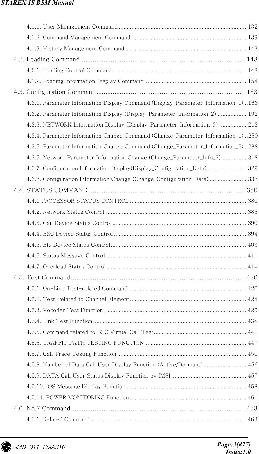
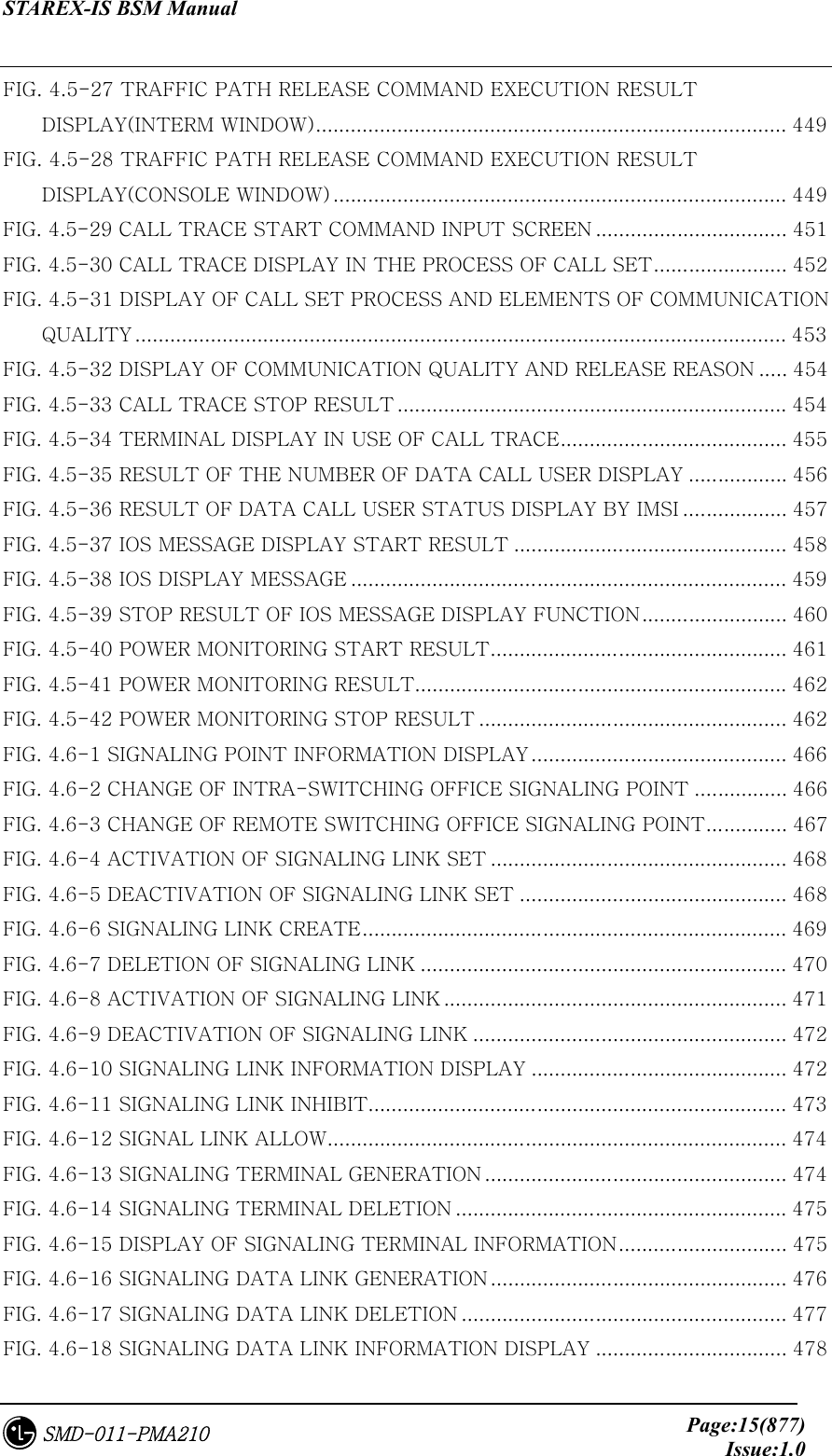
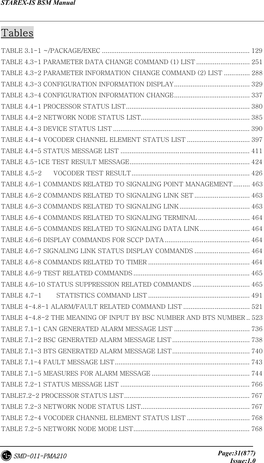
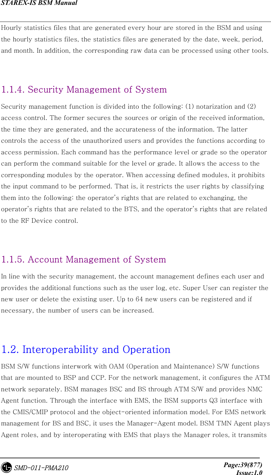
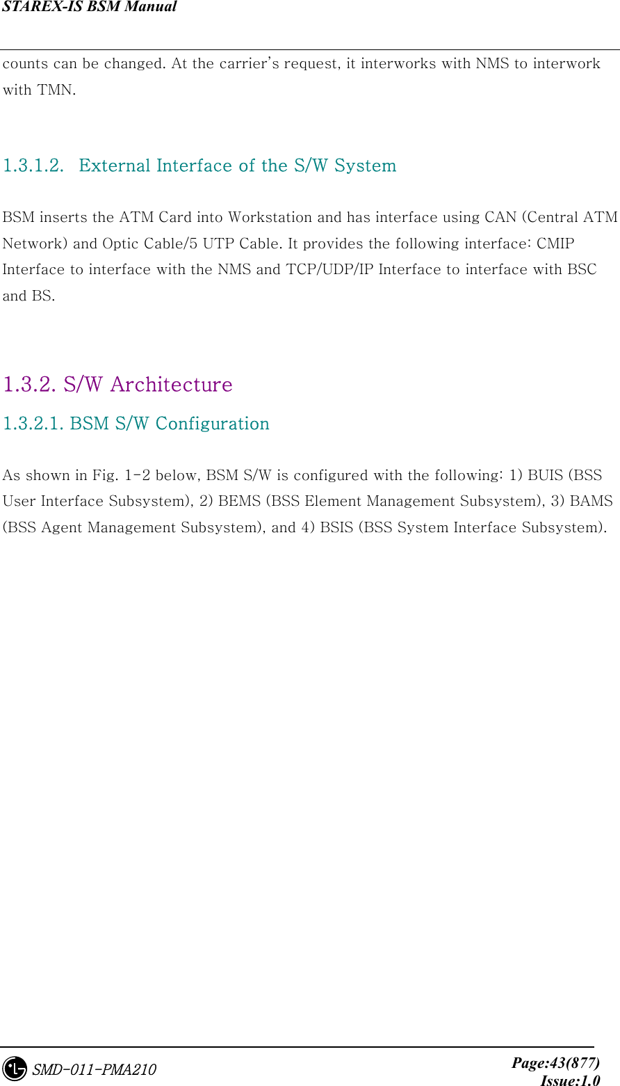
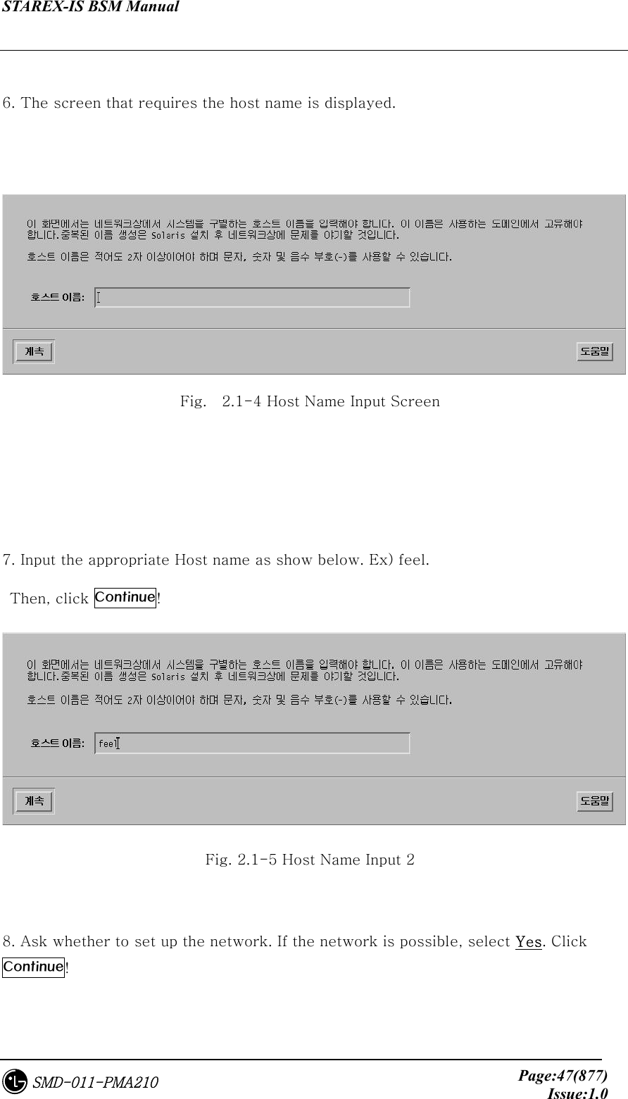
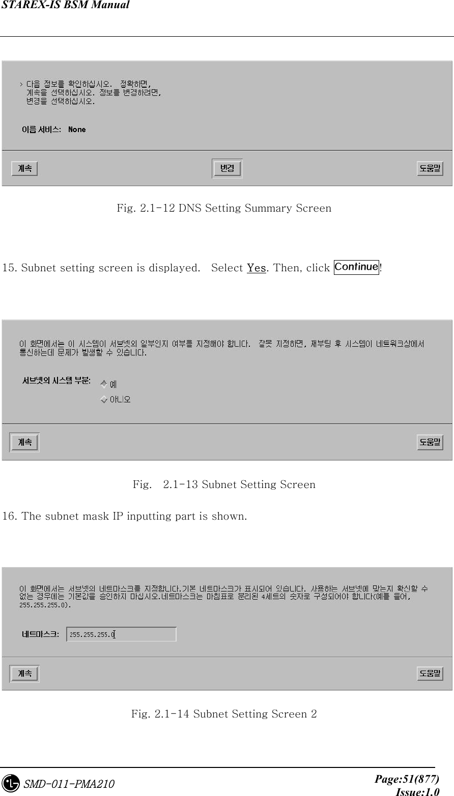
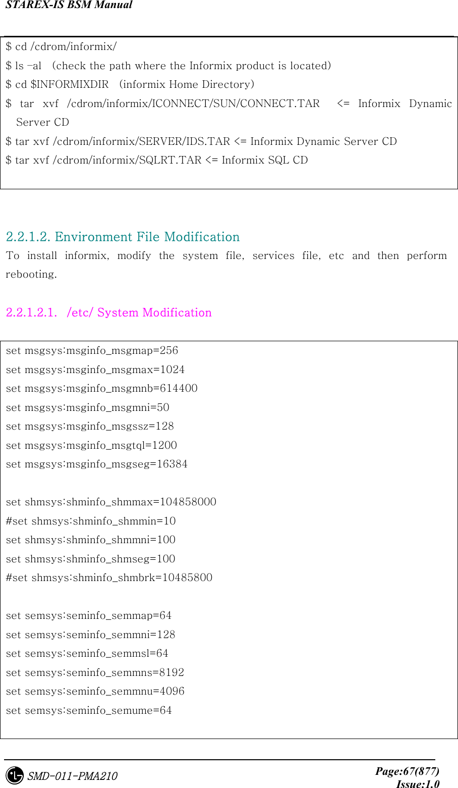
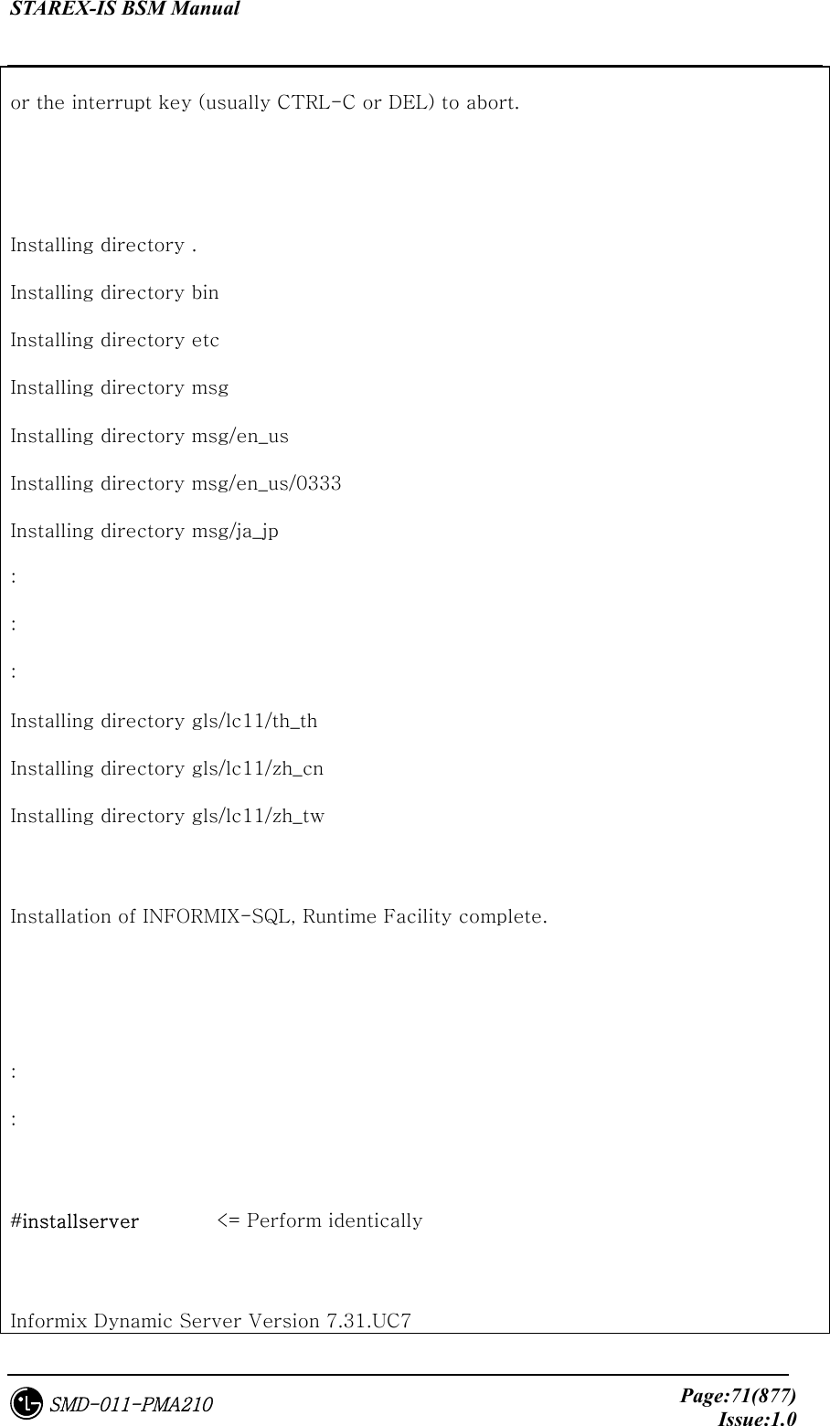
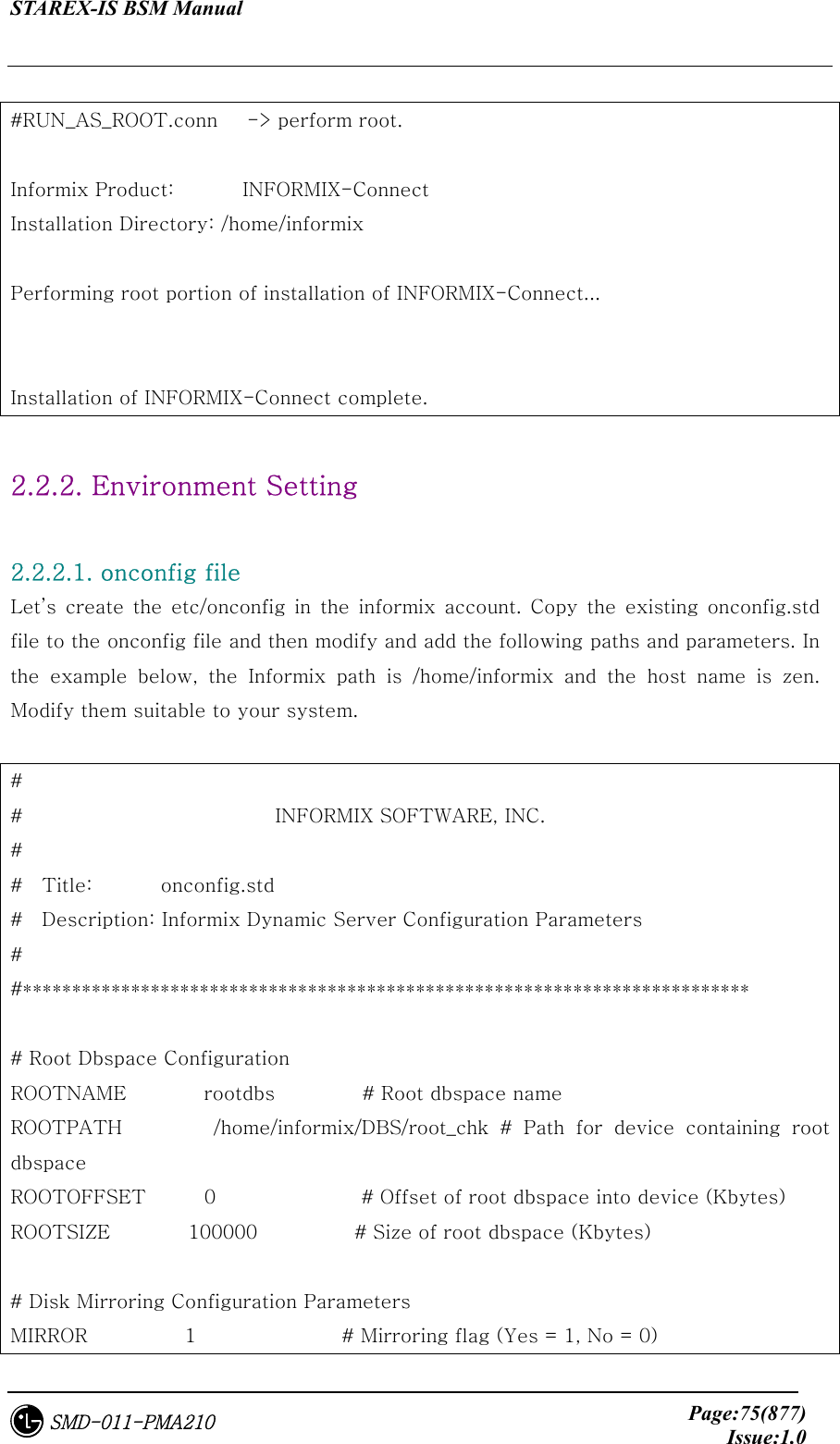
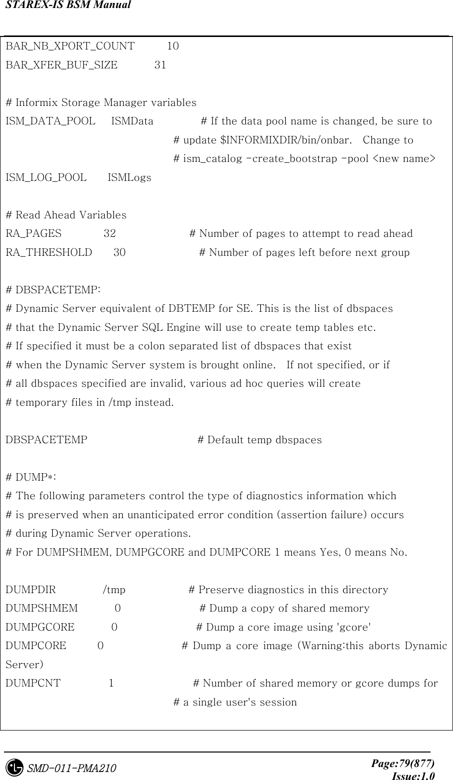
![STAREX-IS BSM Manual Page:83(877)Issue:1.0SMD-011-PMA210 -d spacename [-p pathname -o offset] [-f] [-y] | -f[y] off [DBspace-list] | on [DBspace-list] | -m spacename {-p pathname -o offset -m path offset [-y] | -f filename} | -r spacename [-y] | -s spacename -p pathname -o offset {-O | -D} [-y] } -a - Add a chunk to a DBspace or BLOBspace -c - Create a DBspace or BLOBspace -d - Drop a DBspace, BLOBspace or chunk -f - Change dataskip default for specified DBspaces -m - Add mirroring to an existing DBspace or BLOBspace -r - Turn mirroring off for a DBspace or BLOBspace -s - Change the status of a chunk Now, expand the DB space. #cd DBS #touch root_chk2 <= chunk create #chmod 660 root_chk2 #onspaces -a rootdbs -p /home2/informix/DBS/root_chk2 -o 0 -s 50000 Verifying physical disk space, please wait ... Chunk successfully added. # onstat -d Informix Dynamic Server Version 7.31.UC7 -- On-Line -- Up 10:42:43 -- 62752 Kbytes Dbspaces address number flags fchunk nchunks flags owner name c04a150 1 1 1 2 N informix rootdbs 1 active, 2047 maximum Chunks address chk/dbs offset size free bpages flags pathname c04a210 1 1 0 50000 28913 PO- /home2/informix/DBS/root_chk](https://usermanual.wiki/LG-Electronics-USA/3G1XINBTS.Users-Manual-Part-A/User-Guide-178301-Page-84.png)
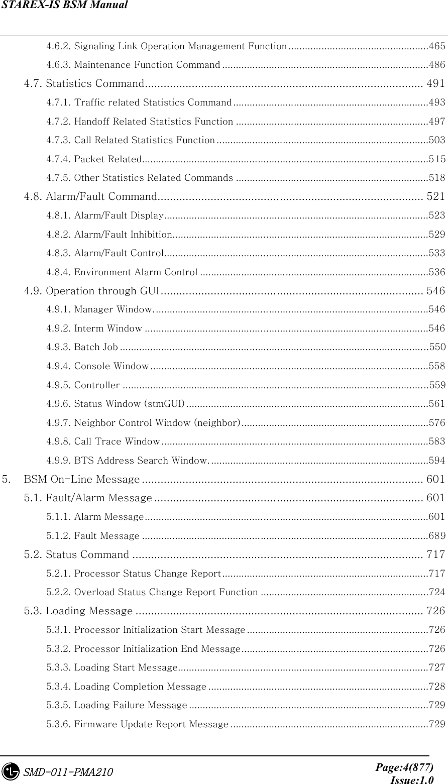
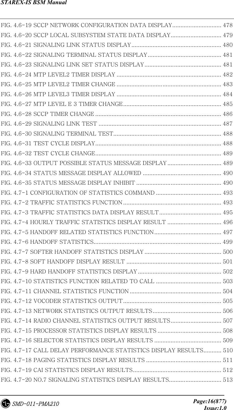
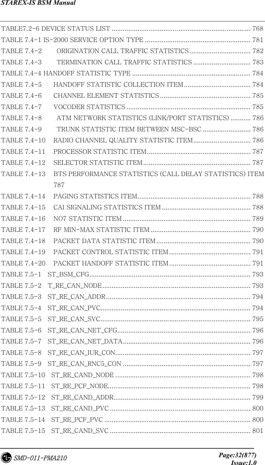
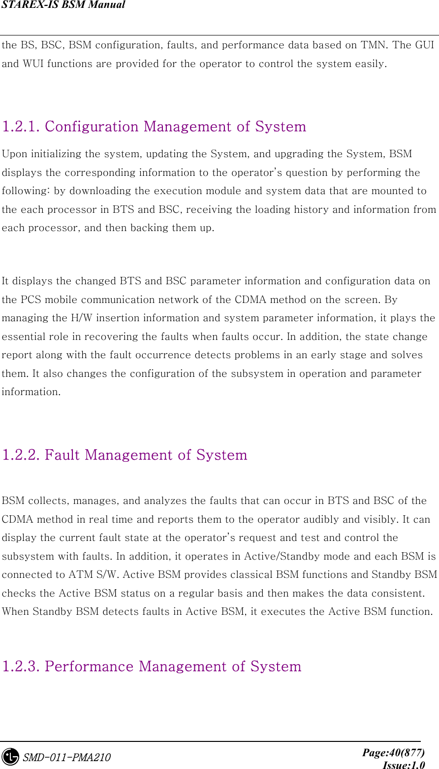
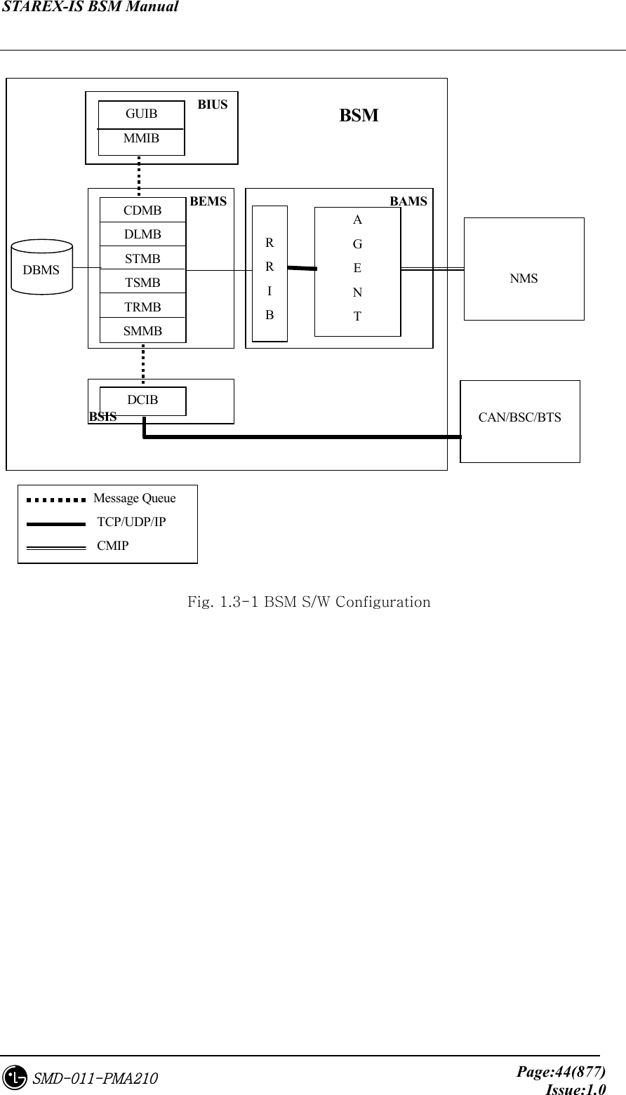
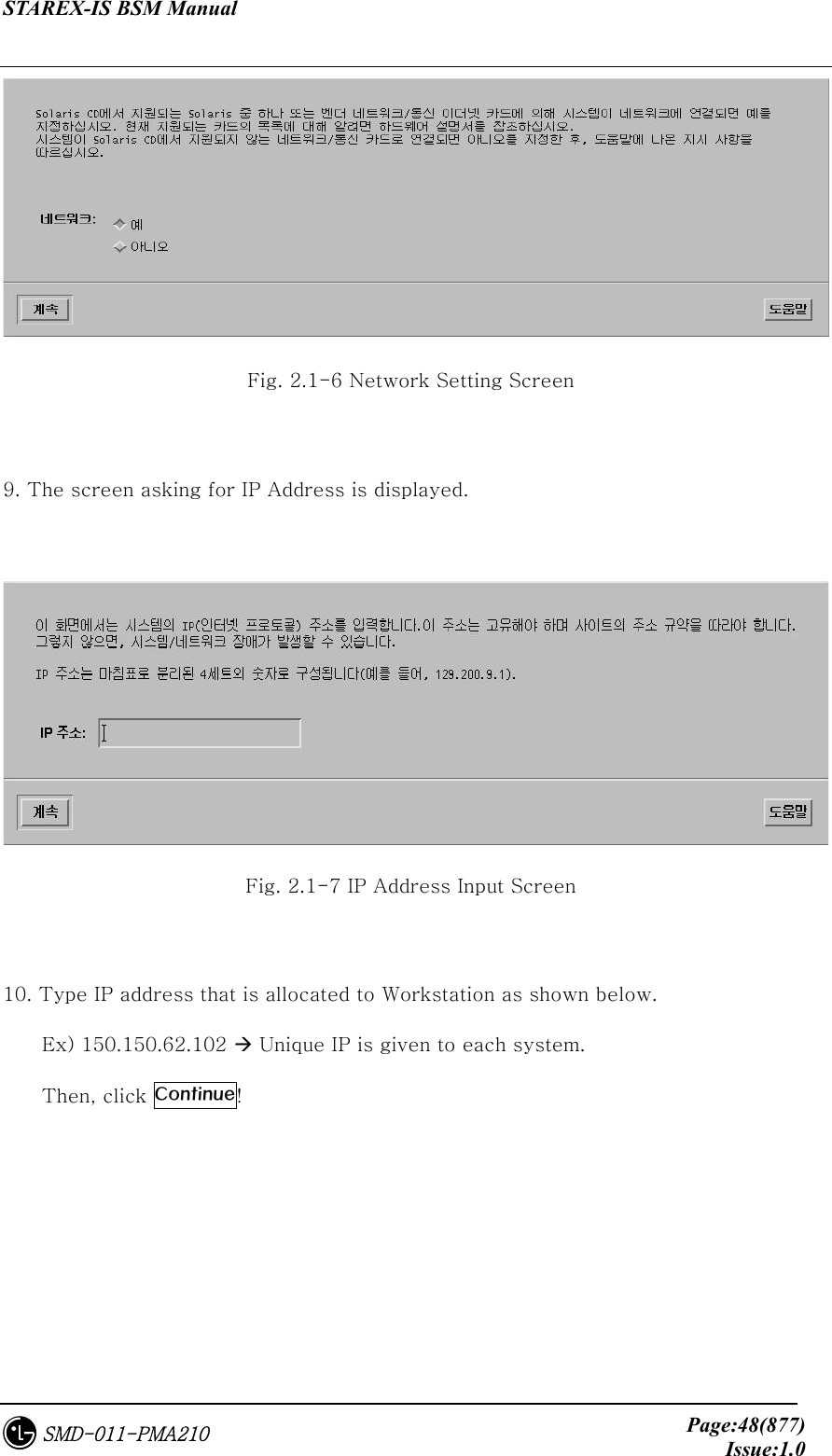
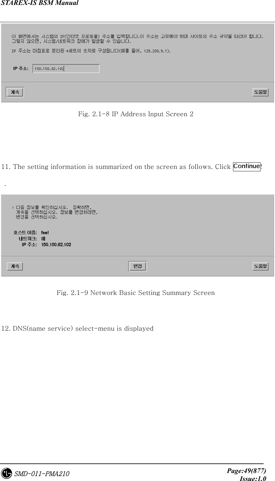
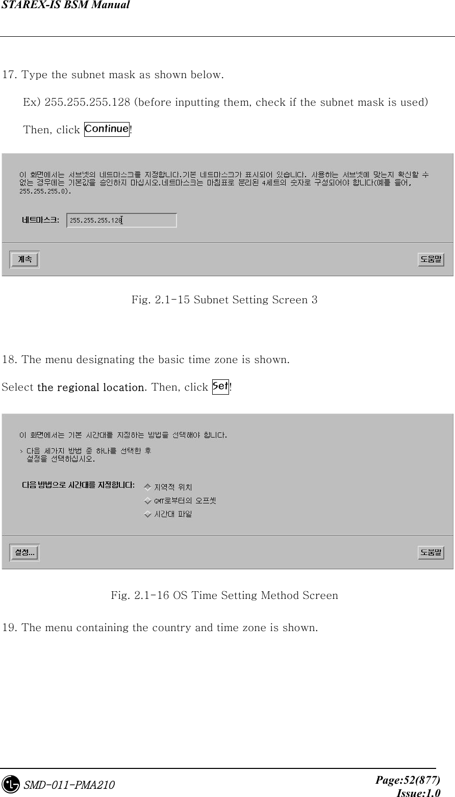
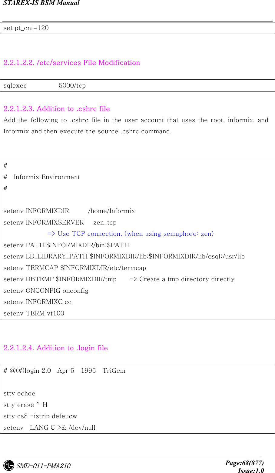
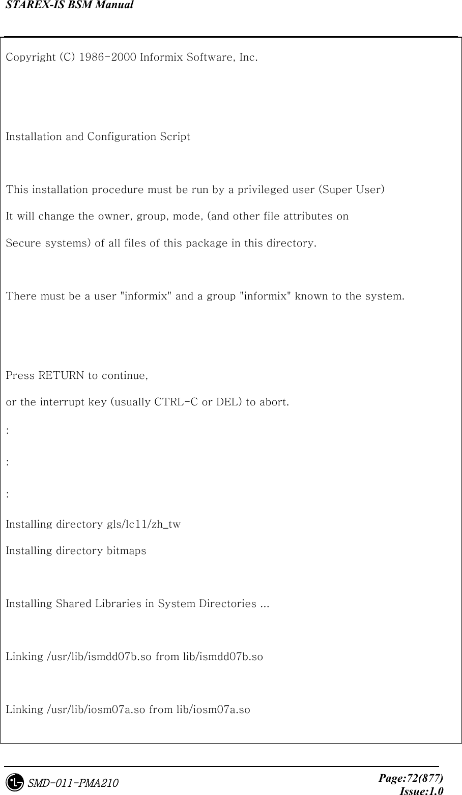
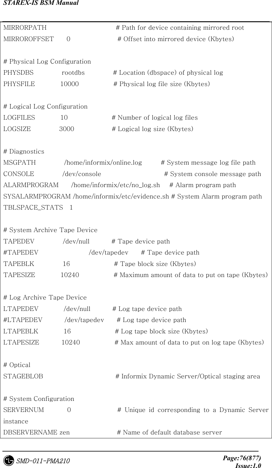
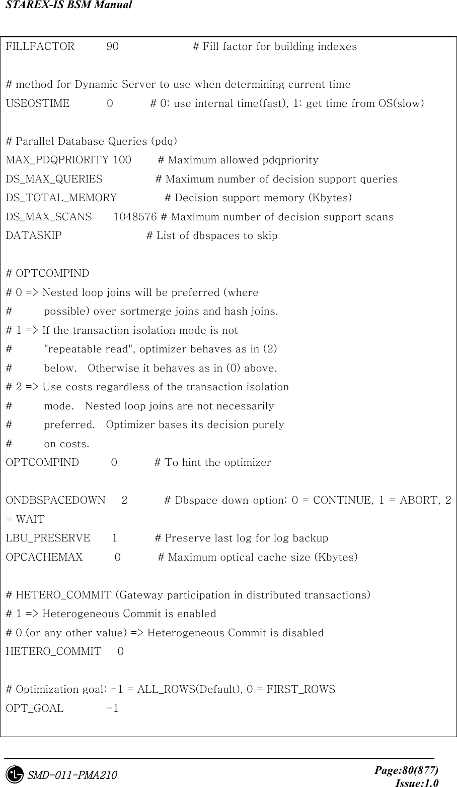
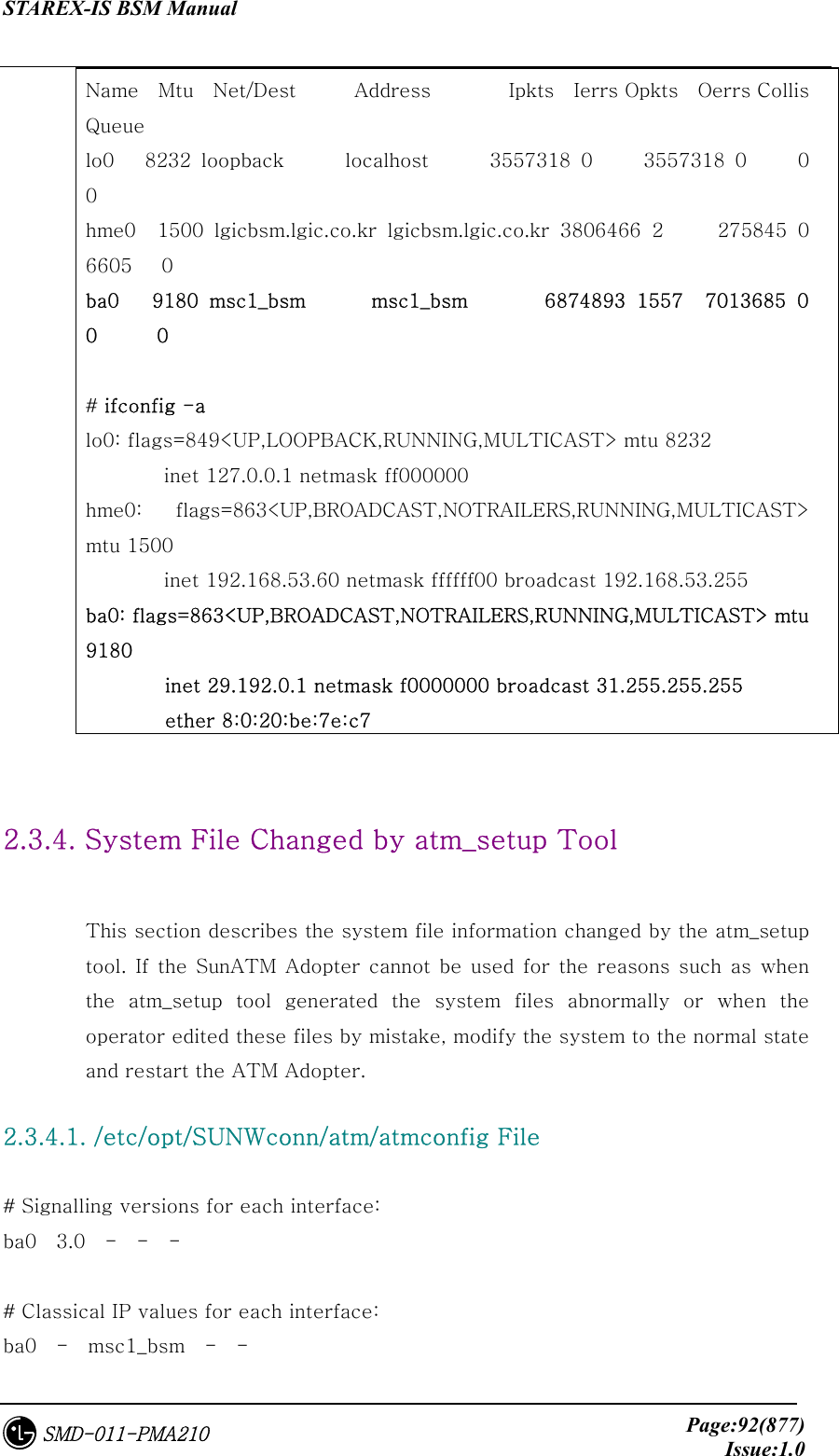
![STAREX-IS BSM Manual Page:88(877)Issue:1.0SMD-011-PMA210 permission during the process of installing this package. Do you want to continue with the installation of <SUNWatm> [y,n,?] y Installing SunATM Device Drivers as <SUNWatm> ## Installing part 1 of 1. /etc/init.d/sunatm /etc/opt/SUNWconn/atm/aarconfig.template /etc/opt/SUNWconn/atm/atmconfig.template /etc/opt/SUNWconn/atm/atmf.mib /etc/opt/SUNWconn/atm/bin/aarsetup /etc/opt/SUNWconn/atm/bin/aarstat /etc/opt/SUNWconn/atm/bin/atmadmin /etc/opt/SUNWconn/atm/bin/atmarp /etc/opt/SUNWconn/atm/bin/atmgetmac ...Ellipsis... /kernel/mod/sscop /platform/SUNW,Ultra-4FT/kernel/drv/ba [ verifying class <base> ] /etc/rc2.d/S00sunatm <linked pathname> ## Executing postinstall script. You will need to edit the config files in /etc/opt/SUNWconn/atm to specify your ATM configuration. As an alternative to manually editing the files, you may also run /etc/opt/SUNWconn/bin/atmadmin to set up your configuration. Refer to the SunATM User's Guide for more information on atmadmin and the ATM configuration files. Installation of <SUNWatm> was successful. Processing package instance <SUNWatmu> from </tmp/atm_setup/sunatm_4_0_update_1/Product>](https://usermanual.wiki/LG-Electronics-USA/3G1XINBTS.Users-Manual-Part-A/User-Guide-178301-Page-89.png)
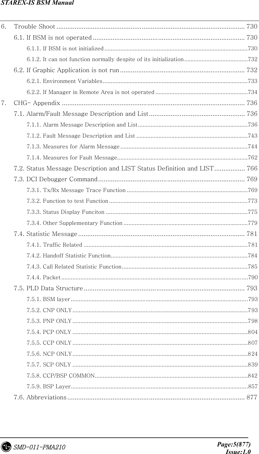
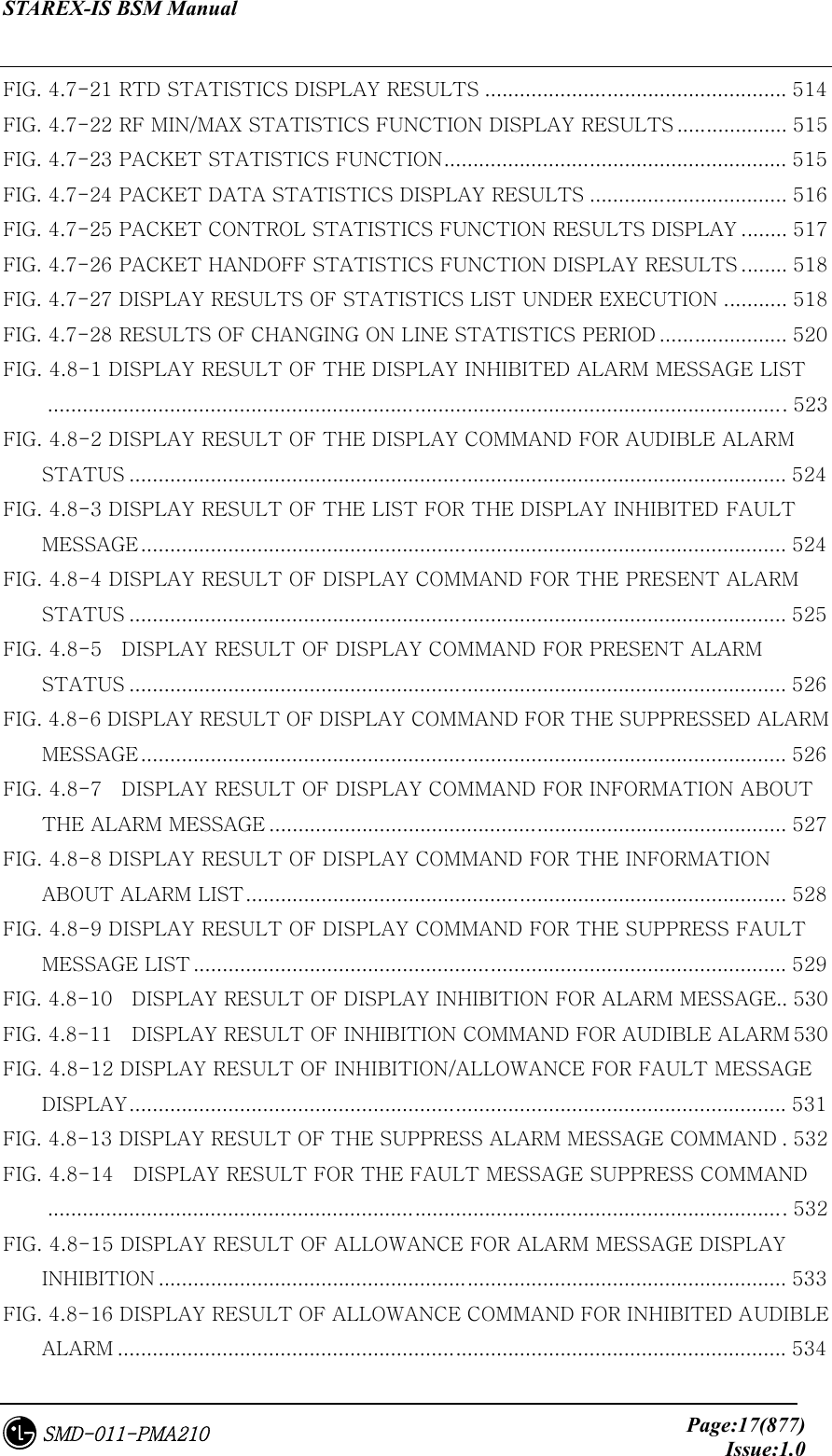
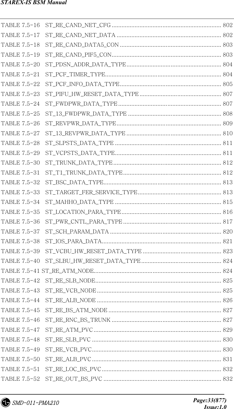
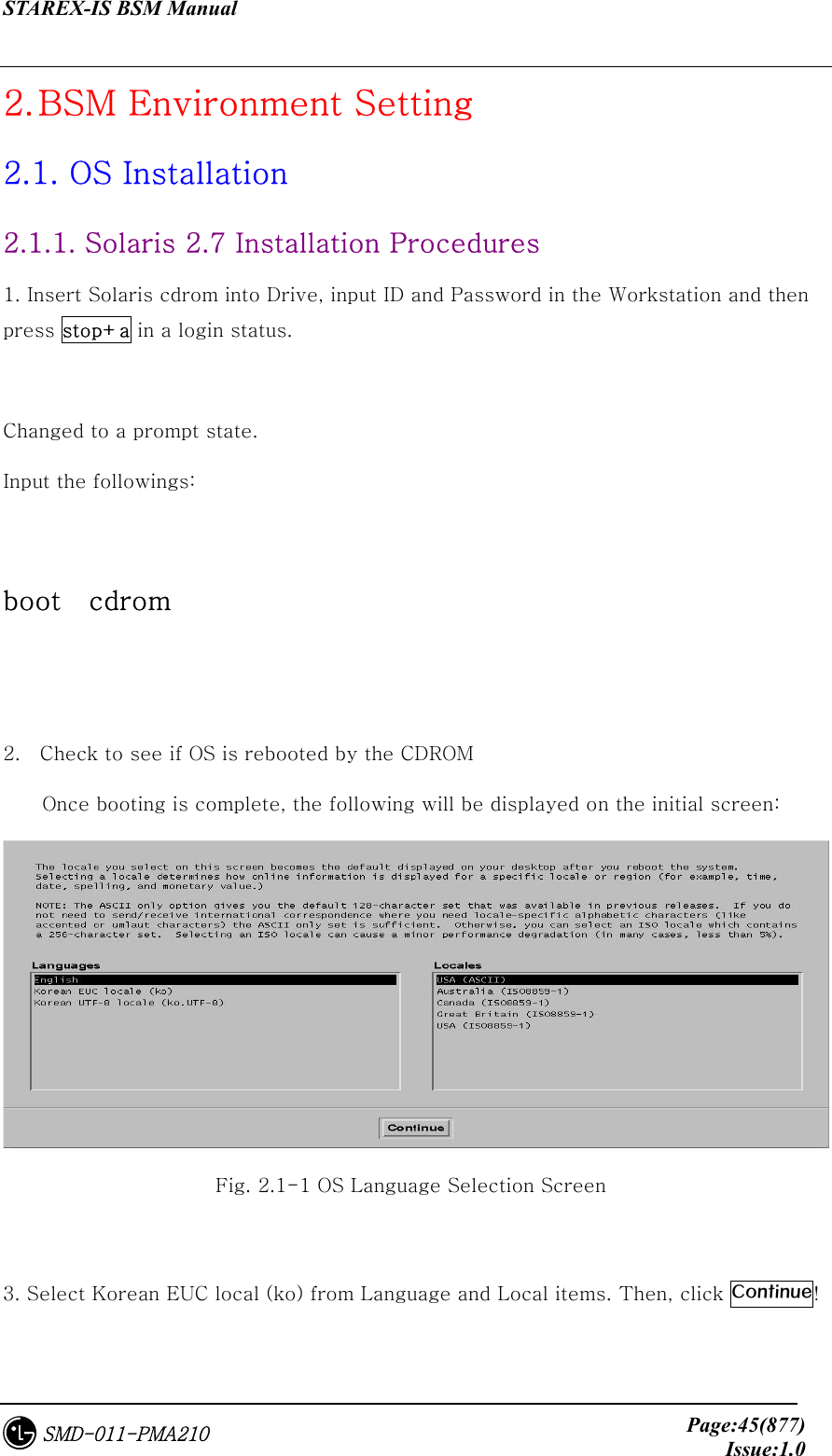
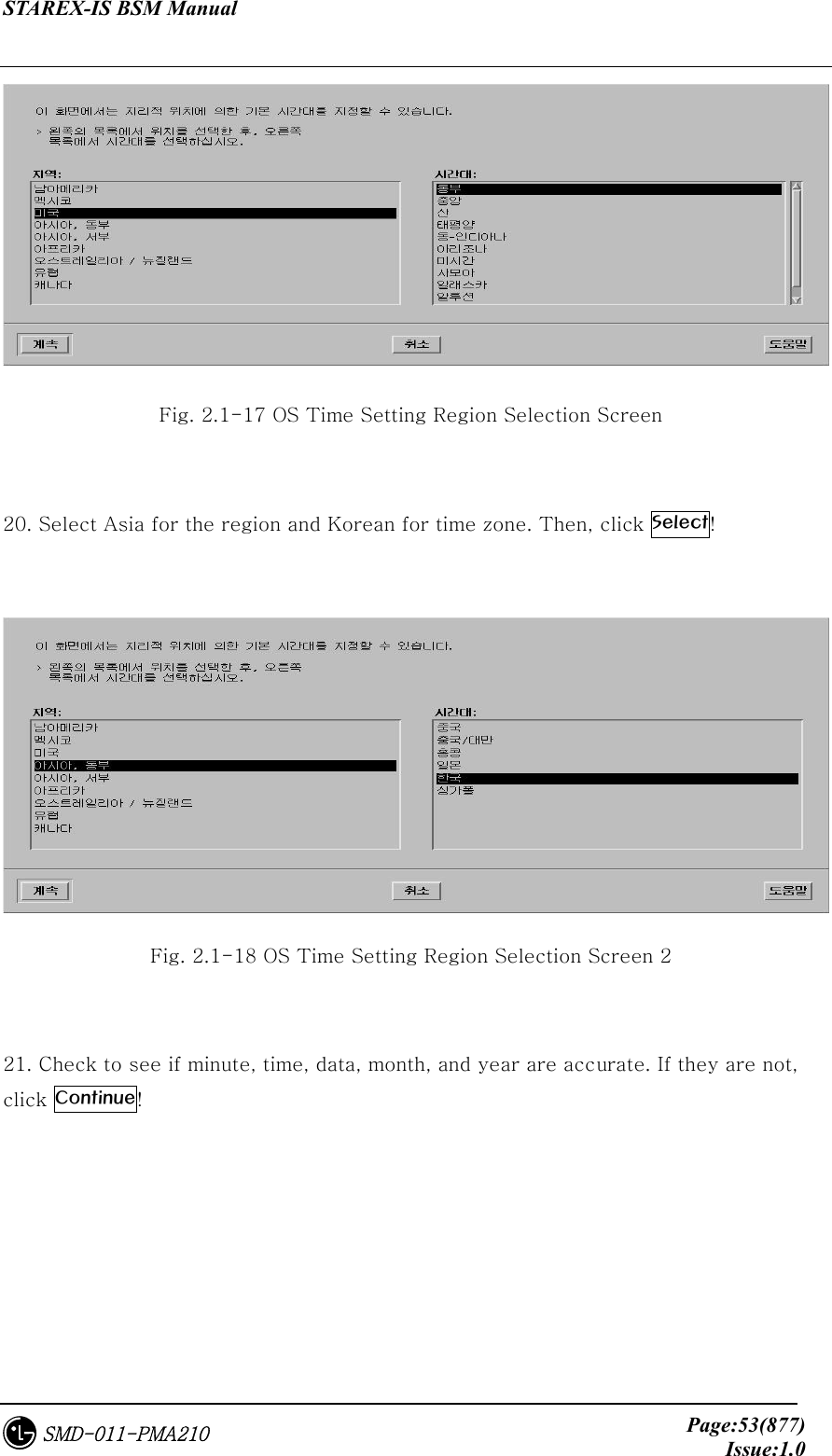
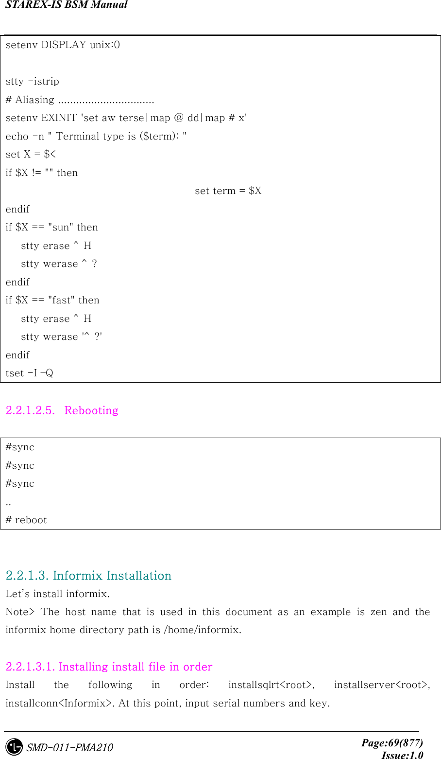
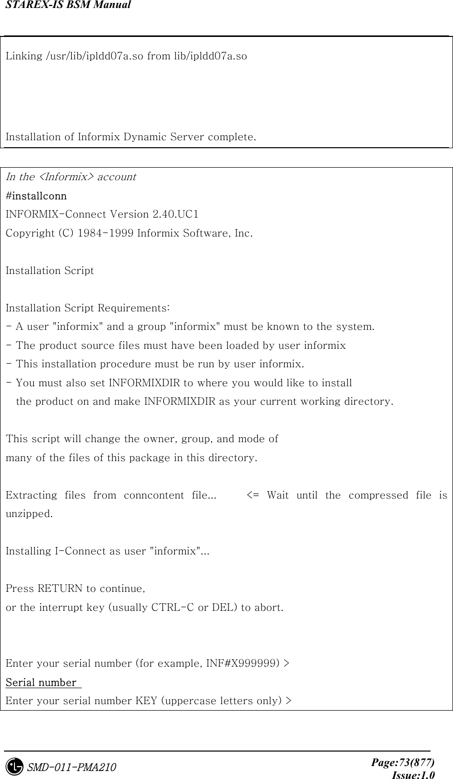
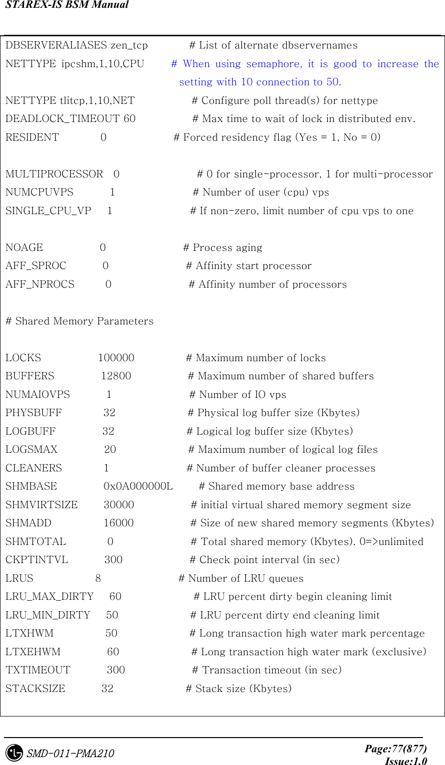
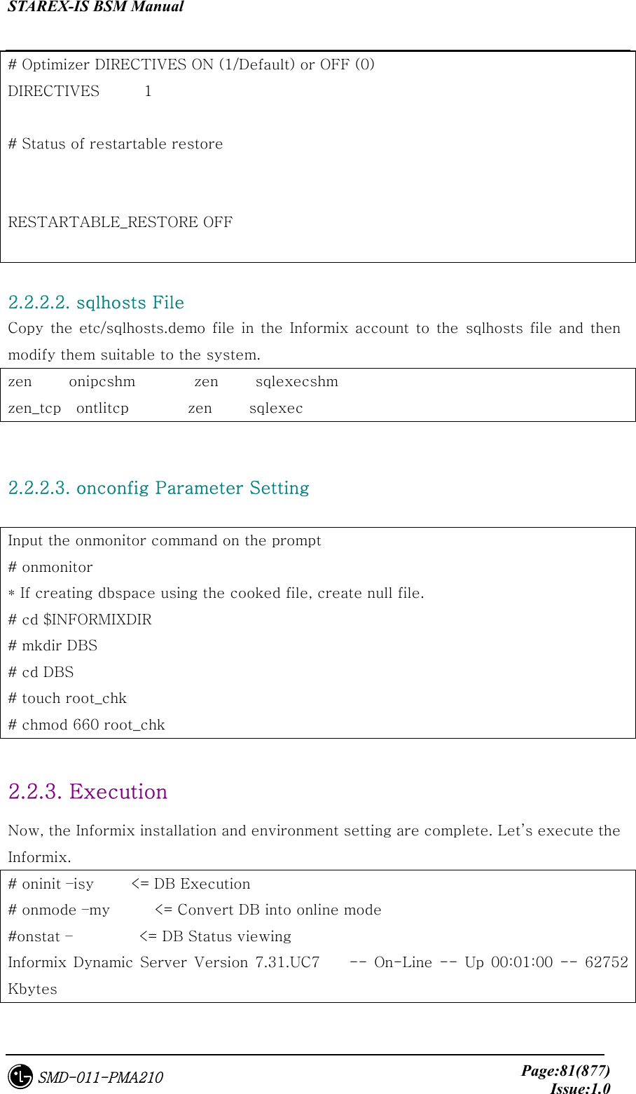
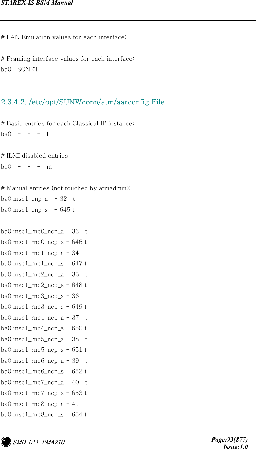
![STAREX-IS BSM Manual Page:89(877)Issue:1.0SMD-011-PMA210 SunATM Runtime Support Software (sparc) 4.0.1,REV=1999.4.27.18 Copyright 1999 Sun Microsystems, Inc. All rights reserved. Using </opt> as the package base directory. ## Processing package information. ## Processing system information. ## Verifying package dependencies. ## Verifying disk space requirements. ## Checking for conflicts with packages already installed. ## Checking for setuid/setgid programs. Installing SunATM Runtime Support Software as <SUNWatmu> ## Installing part 1 of 1. /opt/SUNWconn/atm/examples/Makefile /opt/SUNWconn/atm/examples/dltst.c /opt/SUNWconn/atm/examples/raw.c /opt/SUNWconn/atm/examples/tstqcc.c /opt/SUNWconn/atm/examples/xdump.c /opt/SUNWconn/atm/man/man1m/aarsetup.1m /opt/SUNWconn/atm/man/man1m/aarstat.1m /opt/SUNWconn/atm/man/man1m/atmadmin.1m ...Ellipsis... /opt/SUNWconn/man/man9f/qcc_unpack_status.9f <symbolic link> /opt/SUNWconn/man/man9f/qcc_unpack_status_enq.9f <symbolic link> [ verifying class <none> ] Installation of <SUNWatmu> was successful. Processing package instance <SUNWatma> from </tmp/atm_setup/sunatm_4_0_update_1/Product> SunATM Interim Api Support Software (sparc) 4.0.1,REV=1999.4.27.18 Copyright 1999 Sun Microsystems, Inc. All rights reserved. Using </opt> as the package base directory.](https://usermanual.wiki/LG-Electronics-USA/3G1XINBTS.Users-Manual-Part-A/User-Guide-178301-Page-90.png)
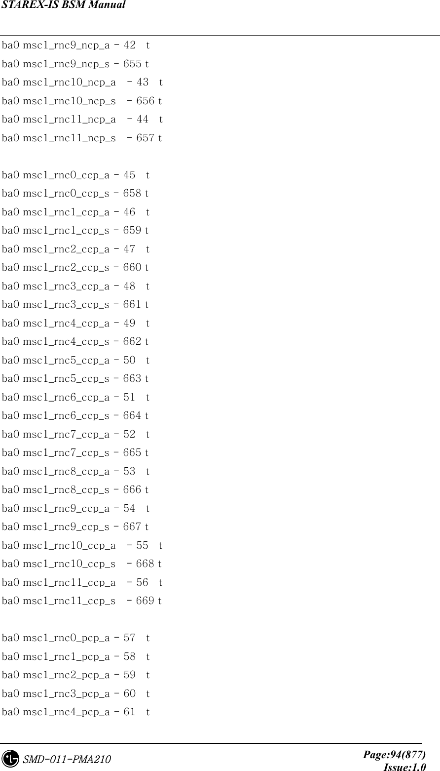
![STAREX-IS BSM Manual Page:90(877)Issue:1.0SMD-011-PMA210 ## Processing package information. ## Processing system information. ## Verifying package dependencies. ## Verifying disk space requirements. ## Checking for conflicts with packages already installed. The following files are already installed on the system and are being used by another package: /opt/SUNWconn <attribute change only> /opt/SUNWconn/atm <attribute change only> Do you want to install these conflicting files [y,n,?,q] y ## Checking for setuid/setgid programs. Installing SunATM Interim Api Support Software as <SUNWatma> ## Installing part 1 of 1. /opt/SUNWconn/atm/include/atm/atm.h /opt/SUNWconn/atm/include/atm/atmioctl.h /opt/SUNWconn/atm/include/atm/limits.h /opt/SUNWconn/atm/include/atm/qcc.h /opt/SUNWconn/atm/include/atm/qccdefs.h /opt/SUNWconn/atm/include/atm/qccioctl.h /opt/SUNWconn/atm/include/atm/qcctypes.h /opt/SUNWconn/atm/include/atm/types.h /opt/SUNWconn/atm/lib/libatm.a ...Ellipsis... /opt/SUNWconn/lib/sparcv9/libatm.a <symbolic link> [ verifying class <base> ] Installation of <SUNWatma> was successful. Installed device drivers listing ............. ############ system SUNWatm SunATM Device Drivers application SUNWatma SunATM Interim Api Support Software application SUNWatmu SunATM Runtime Support Software](https://usermanual.wiki/LG-Electronics-USA/3G1XINBTS.Users-Manual-Part-A/User-Guide-178301-Page-91.png)


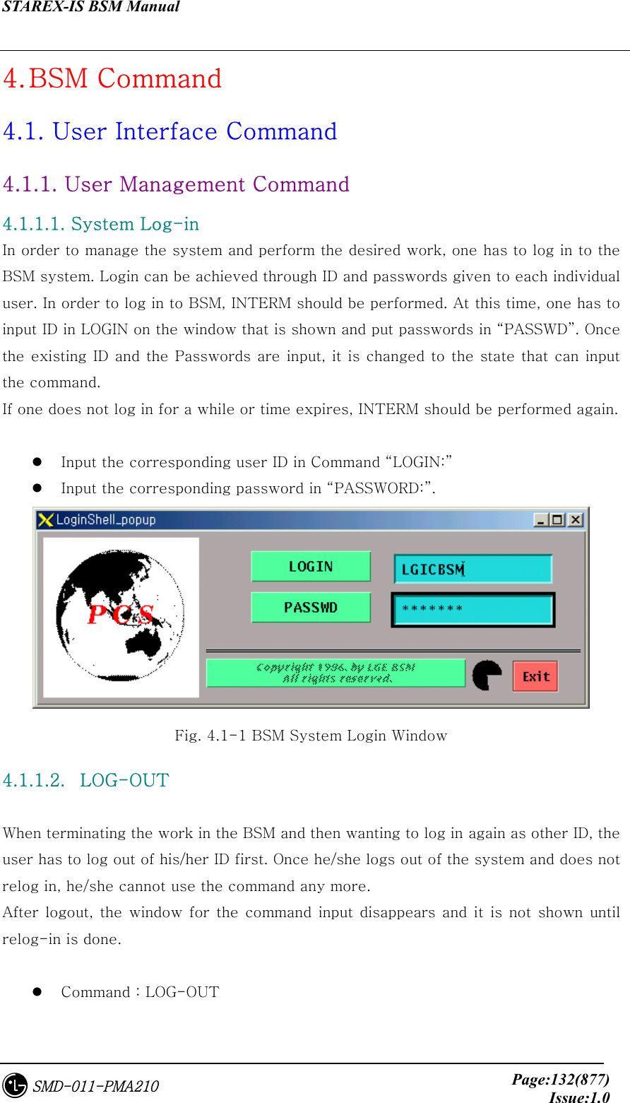
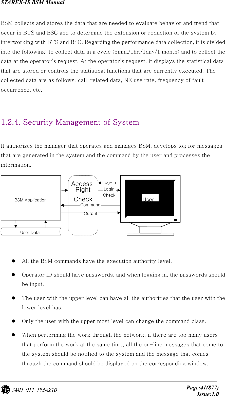
![STAREX-IS BSM Manual Page:133(877)Issue:1.0SMD-011-PMA210 Input : LOG-OUT; Output Fig. 4.1-2 Log-out 4.1.1.3. User Addition To operate and maintain the system, the user should register ID. The right to register ID can be obtained from the manger in the first class. The newly registered ID is set identically with initial passwords and ID and for security reason, the password for the newly registered ID should be changed. The ID that is to be registered should be original. That is, it should not be overlapped with existing ones. It can be registered as the second or third class. ID should be within 15 letters. Command : ADD-USR:USR=a, CLS=b; a : User ID [ String ] b : Class [Number 2 or 3 ] Input : ADD-USER:USER=USER1,CLS=2; Output](https://usermanual.wiki/LG-Electronics-USA/3G1XINBTS.Users-Manual-Part-A/User-Guide-178301-Page-134.png)
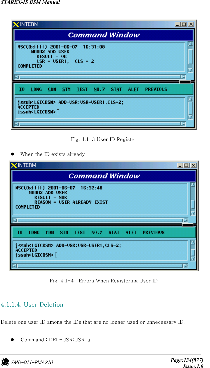
![STAREX-IS BSM Manual Page:135(877)Issue:1.0SMD-011-PMA210 a : User ID to be deleted [ String ] Input : DEL-USR:USR=USER1; Output Fig. 4.1-5 User ID Deletion When deleting ID that does not exist Fig. 4.1-6 Errors When Deleting User ID That Does Not Exist](https://usermanual.wiki/LG-Electronics-USA/3G1XINBTS.Users-Manual-Part-A/User-Guide-178301-Page-136.png)
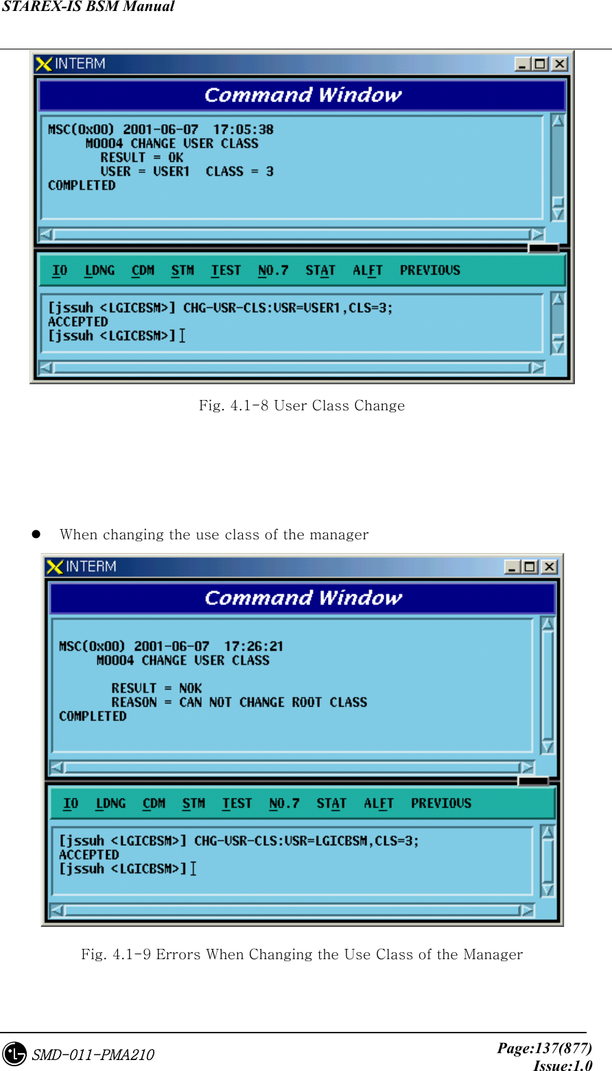
![STAREX-IS BSM Manual Page:136(877)Issue:1.0SMD-011-PMA210 When deleting manager class ID Fig. 4.1-7 Errors When Deleting the Manager Class ID 4.1.1.5. User Class Change Broaden the range of the command or narrow it down by changing the use class of the corresponding user. Command CHG-USR-CLS:USR=a,CLS=b a: User ID[String] b: Class [2-3] Input CHG-USR-CLS:USR=USER1,CLS=3; Output](https://usermanual.wiki/LG-Electronics-USA/3G1XINBTS.Users-Manual-Part-A/User-Guide-178301-Page-137.png)
![STAREX-IS BSM Manual Page:138(877)Issue:1.0SMD-011-PMA210 4.1.1.6. User Information Display Display registered User ID and class. Command DIS-USR-INFO[USR=a] a: User ID[String] Input CHG-USR-INFO:USR=USER1; Output Fig. 4.1-10 User Information Display 4.1.1.7. User Password Change Change ID and Password in use. In particular, since the ID of the first time registered user should be identical with the password, change the password as follows for security reasons. Command CHG-PWD Input CHG-PWD Output Input the OLD PASSWORD and NEWPASSWORD one more time and check them.](https://usermanual.wiki/LG-Electronics-USA/3G1XINBTS.Users-Manual-Part-A/User-Guide-178301-Page-139.png)
![STAREX-IS BSM Manual Page:139(877)Issue:1.0SMD-011-PMA210 Fig. 4.1-11 User Password Change 4.1.2. Command Management Command 4.1.2.1. Command Class Modification Modify the minimum class that can execute the registered command. If the command class is n, one has to log in as ID that is more than n class to use this command. Command CHG-CMD-CLS:CRN=a,CLS=b a : Command Reference Number [0~9999] b : Class [1~3] Input CHG-CMD-CLS:CRN=0300,CLS=1 Output](https://usermanual.wiki/LG-Electronics-USA/3G1XINBTS.Users-Manual-Part-A/User-Guide-178301-Page-140.png)
![STAREX-IS BSM Manual Page:140(877)Issue:1.0SMD-011-PMA210 Fig. 4.1-12 Command Class Modification 4.1.2.2. Command Class Display One can see the command of the corresponding class by designating the class that is desired to be displayed. Command DIS-CMD-CLS:CLS=a; a : Class [1~3] Input DIS-CMD-CLS:CLS=3;](https://usermanual.wiki/LG-Electronics-USA/3G1XINBTS.Users-Manual-Part-A/User-Guide-178301-Page-141.png)
![STAREX-IS BSM Manual Page:141(877)Issue:1.0SMD-011-PMA210 Fig. 4.1-13 Command Class Display 4.1.2.3. Command Information Display by Name Display the syntax to use the information on the registered commands. Command DIS-CMD-INFO:VERB=a a : Command [Note : The command discriminator is determined to be &]](https://usermanual.wiki/LG-Electronics-USA/3G1XINBTS.Users-Manual-Part-A/User-Guide-178301-Page-142.png)
![STAREX-IS BSM Manual Page:142(877)Issue:1.0SMD-011-PMA210 Input DIS-CMD-INFO:DIS&CMD&INFO; Output Fig. 4.1-14 Command Information Display by Name 4.1.2.4. Command Information by CRN Display the command information by CRN which is designated for each command. Command DIS-CRN-INFO:CRN=a a : Command Reference Number [0~9999] Input DIS-CRN-INFO:CRN=0200; Output](https://usermanual.wiki/LG-Electronics-USA/3G1XINBTS.Users-Manual-Part-A/User-Guide-178301-Page-143.png)
![STAREX-IS BSM Manual Page:143(877)Issue:1.0SMD-011-PMA210 Fig. 4.1-15 Command Information Display by CRN 4.1.3. History Management Command 4.1.3.1. Command History Display •Command DIS-CMD-HIS[:[DATE=a][,STM=b][,ETM=c][,USR=d]] a : Date [MMDD] MM : Month [1-12] DD : Day [1-day last] b : Start Time [HHMMSS] HH : Hour [00-24] MM : Min [00-60] SS : Sec [00-60] c : End Time [HHMMSS] d : User ID [string]](https://usermanual.wiki/LG-Electronics-USA/3G1XINBTS.Users-Manual-Part-A/User-Guide-178301-Page-144.png)
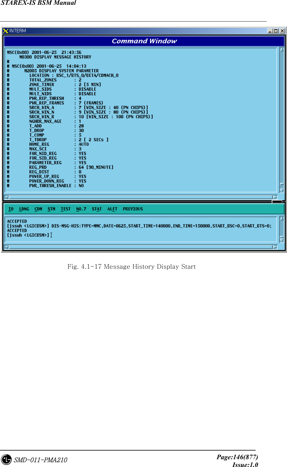
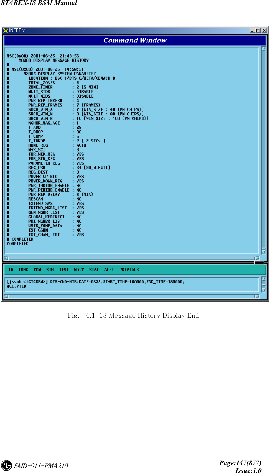
![STAREX-IS BSM Manual Page:144(877)Issue:1.0SMD-011-PMA210 Input DIS-CMD-HIS:DATE=0625,STM=160000,ETM=180000 Output Fig. 4.1-16 Command History Display 4.1.3.2. Message History Display Command DIS-MSG-HIS:TYPE=a,[DATE=b],[START_TIME=c],[END_TIME=d] ,[START_BSC=e],[END_BSC=f],[START_BTSGRP=g], [END_BTSGRP=h] ,[START_BTSSUB=i],[END_BTSSUB=j],[PRN=k]; a : Message Type [SYS, MMC, STS, FLT, ALM] SYS : system message MMC : MMC command STS : status message](https://usermanual.wiki/LG-Electronics-USA/3G1XINBTS.Users-Manual-Part-A/User-Guide-178301-Page-145.png)
![STAREX-IS BSM Manual Page:145(877)Issue:1.0SMD-011-PMA210 FLT : fault message ALM : alarm message b : Date [MMDD] MM : Month [1-12] DD : Day [1-day last] c : Start Time [HHMMSS] HH : Hour [00-24] MM : Min [00-60] SS : Sec [00-60] d : End Time [HHMMSS] e : Start BSC number[0 ~ 127] f : End BSC number[0 ~ 127] g : Start BTS GRP number[0 ~ 47] h : End BTS GRP number[0 ~ 47] i : Start BTS SUB number[0 ~ 3] j : End BTS SUB number[0 ~ 3] k : Message number[0 ~ 9999] Input DIS-MSG-HIS:TYPE=MMC,DATE=0625,START_TIME=140000, END_TIME=150000, START_BSC=0, [START_BTSGRP=0; Output](https://usermanual.wiki/LG-Electronics-USA/3G1XINBTS.Users-Manual-Part-A/User-Guide-178301-Page-146.png)
![STAREX-IS BSM Manual Page:148(877)Issue:1.0SMD-011-PMA210 4.2. Loading Command 4.2.1. Loading Control Command 4.2.1.1. Block Loading (DOWN-BLK) This command is used to download specific S/W blocks to target processors from BSM. The target processors that can designate the block loading are as follows: CNP, PNP, PCP, PMP, NCP, CCP, SCP, BSP, SMP, and VMP. This command is used to download blocks that need subloading to the lower level processors of the designated target processors. Command : DOWN-BLK:[BSC=a,][BTS=b,]PROC=c,FLASH=d,BLK=e; a : BSC ID [ Number 0~11 ] b : BTS ID [ Number 0~47 ] c : Processor Name [ CNP, PNP, PCP0, PCP1, PCP2, PMP0, PMP1, PMP2, NCP, CCP, SCP, BSP, SMP0, SMP1, SMP2, SMP3, SMP4, VMP0, VMP1, VMP2, VMP3, VMP4, VMP5, VMP6, VMP7 ] d : Whether to update the flash memory [ UPDATE or MAINTAIN ] e : Block Name [ String ] Input : DOWN-BLK:BSC=1,PROC=CCP,FLASH=MAINTAIN,BLK=rcpuser;](https://usermanual.wiki/LG-Electronics-USA/3G1XINBTS.Users-Manual-Part-A/User-Guide-178301-Page-149.png)
![STAREX-IS BSM Manual Page:149(877)Issue:1.0SMD-011-PMA210 Output : Fig. 4.2-1 Blocking Loading Performance Result 4.2.1.2. Activation Loading (ACT-BLK) This command is used to download the specific S/W blocks from BSM to the target processor and then to activate them. The target processors that can designate the activation loading are CNP, PNP, PCP, PMP, NCP, CCP, SCP, BSP, ALP, SMP, and VMP. This command is used to download S/W blocks that are operated in the target processors and to replace blocks which are currently in operation by using the newly downloaded blocks. Command : ACT-BLK:[BSC=a,][BTS=b,]PROC=c,FLASH=d, BLK1=e[,BLK2=e][,BLK3=e]; a : BSC ID [ Number 0~11 ] b : BTS ID [ Number 0~47 ] c : Processor Name[ CNP, PNP, PCP0, PCP1, PCP2, PMP0, PMP1, PMP2, NCP, CCP, SCP, BSP, ALP, SMP0, SMP1, SMP2, SMP3, SMP4, VMP0, VMP1, VMP2, VMP3, VMP4, VMP5, VMP6, VMP7 ] d : Whether to Update Flash Memory [ UPDATE or](https://usermanual.wiki/LG-Electronics-USA/3G1XINBTS.Users-Manual-Part-A/User-Guide-178301-Page-150.png)
![STAREX-IS BSM Manual Page:150(877)Issue:1.0SMD-011-PMA210 MAINTAIN ] e : Block Name [ String ] Input : ACT-BLK:BSC=1,PROC=CCP,FLASH=UPDATE,BLK=ccp_cal; Output : Fig. 4.2-2 Activation Loading Performance Result 4.2.1.3. Flash Memory Update (UPD-FLS) The command to update Flash memory is used to designate memory update as MAINTAIN in the block loading and activation loading and then to record the following: 1) the blocks that are downloaded as a result of the block loading and 2) activation loading command results in the Flash Memory. Command : UPD-FLS:[BSC=a,][BTS=b,]PROC=c ; a : BSC ID [ Number 0~11 ] b : BTS ID [ Number 0~47 ] c : Processor Name [ CNP, PNP, PCP0, PCP1, PCP2, PMP0, PMP1, PMP2, NCP, CCP, SCP, BSP, ALP ] Input : UPD-FLS:BSC=1,PROC=CCP; Output :](https://usermanual.wiki/LG-Electronics-USA/3G1XINBTS.Users-Manual-Part-A/User-Guide-178301-Page-151.png)
![STAREX-IS BSM Manual Page:151(877)Issue:1.0SMD-011-PMA210 Fig. 4.2-3 Flash Memory Update Result 4.2.1.4. Processor Loading Request on the Standby Side (SBY-LDNG-PRC) It is the function that requests the loading to standby side of the processors. The target processors that can perform the Standby loading should be duplicated and both A and B sides should be normally operated. (If they are not duplicated or abnormal, the Standby loading cannot be performed.) The target processors that can request the processor loading on the standby side are as follows: CNP, PNP, PCP, PMP, NCP, CCP, SCP, and BSP. Command : SBY-LDNG-PRC:[BSC=a,][BTS=b,]PROC=c ; a : BSC ID [ Number 0~11 ] b : BTS ID [ Number 0~47 ] c : Processor Name [ CNP, PNP, PCP0, PCP1, PCP2, PMP0, PMP1, PMP2, NCP, CCP, SCP, BSP ] 4.2.1.5. Processor Switching-over (ACT-PRC) The command to switch over the processors is switch over the Active Side of the target processors which operate as NORM(OLD) and NORM(NEW) after performing standby loading.](https://usermanual.wiki/LG-Electronics-USA/3G1XINBTS.Users-Manual-Part-A/User-Guide-178301-Page-152.png)
![STAREX-IS BSM Manual Page:152(877)Issue:1.0SMD-011-PMA210 Command : ACT-PRC:[BSC=a,][BTS=b,]PROC=c ; a : BSC ID [ Number 0~11 ] b : BTS ID [ Number 0~47 ] c : Processor Name [ CNP, PNP, PCP0, PCP1, PCP2, PMP0, PMP1, PMP2, NCP, CCP, SCP, BSP ] 4.2.1.6. Processor Copy (COPY-PRC) The command to copy processors which performed the standby loading and then operate as NORM(OLD) and NORM(NEW) to the Block that received the Standby loading. Command : COPY-PRC:[BSC=a,][BTS=b,]PROC=c ; a : BSC ID [ Number 0~11 ] b : BTS ID [ Number 0~47 ] c : Processor Name [ CNP, PNP, PCP0, PCP1, PCP2, PMP0, PMP1, PMP2, NCP, CCP, SCP, BSP ] 4.2.1.7. Firmware Loading (LOAD-FIRM) The command to load the firmware is used to download the firmware data to fuse to the target processors or processors that serve as device servers. Command : LOAD-FIRM :[BSC=a,] [BTS=b,] PROC_L1=c [,PROC_L2=d], FILENAME=e; a : BSC ID [ Number 0~11 ] b : BTS ID [ Number 0~47 ] c : Level 1 Processor [ CNP, PNP, PCP0, PCP1, PCP2, PMP0, PMP1, PMP2, NCP, CCP, SCP, BSP ] d : Level 2 Processor [ ASCA, ASIA0, ASIA1, ASIA2, ASIA3, ENP, CRP, PIP0, PIP1, PIP2, PIP3, PIP4, PIP5, PIP6, PIP7, PIP8, PIP9, PIP10, ALP, SMP0, SMP1, SMP2, SMP3, SMP4, VMP0, VMP1, VMP2, VMP3, VMP4, VMP5, VMP6,](https://usermanual.wiki/LG-Electronics-USA/3G1XINBTS.Users-Manual-Part-A/User-Guide-178301-Page-153.png)
![STAREX-IS BSM Manual Page:153(877)Issue:1.0SMD-011-PMA210 VMP7, LICA0, LICA1,LICA2 ] e : Firmware Data File Name [ String ] 4.2.1.8. Firmware Update (UPD-FIRM) After downloading the firmware data to fuse to target processor or processors that serve as the device servers using the firmware loading command, it downloads or fuse firmware data to target processors to devices using the firmware update command. Command : UPD-FIRM : [BSC=a] [,BTS=b] ,PROC_L1=c [,PROC_L2=d] [,PROC_L3=e] [,SIDE=f] ,FILENAME=g ,TYPE=h; a : BSC ID [ Number 0~11 ] b : BTS ID [ Number 0~47 ] c : :Level 1 Processor [ CNP, PNP, PCP0, PCP1, PCP2, PMP0, PMP1, PMP2, NCP, CCP, SCP, BSP ] d : Level 2 Processor [ ASCA, ASIA_ALL, ASIA0, ASIA1, ASIA2, ASIA3, ENP, CRP, PIP_ALL, PIP0, PIP1, PIP2, PIP3, PIP4, PIP5, PIP6, PIP7, PIP8, PIP9, PIP10, ALP, SMP0, SMP1, SMP2, SMP3, SMP4, VMP0, VMP1, VMP2, VMP3, VMP4, VMP5, VMP6, VMP7, LICA_ALL, LICA0, LICA1, LICA2 ] e : Level 3 Processor [ ALMA_ALL, ALMA0, ALMA1, ALPA_ALL, ALPA0_0, ALPA0_1, ALPA0_2, ALPA0_3, ALPA0_4, ALPA1_0, ALPA1_1, ALPA1_2, ALPA1_3, ALPA1_4, SLP_ALL, SLP0, SLP1, SLP2, SLP3, SLP4, SLP5, SLP6, SLP7, SLP8, SLP9, SLP10, SLP11, SLP12, SLP13, SLP14, SLP15, SLP16, SLP17, SLP18, SLP19, VCP_ALL, VCP0, VCP1, VCP2, VCP3,](https://usermanual.wiki/LG-Electronics-USA/3G1XINBTS.Users-Manual-Part-A/User-Guide-178301-Page-154.png)
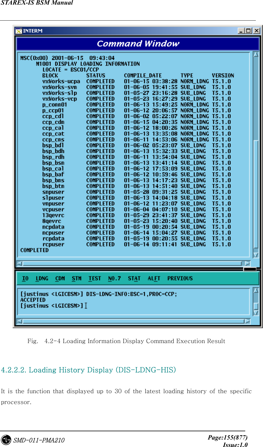
![STAREX-IS BSM Manual Page:154(877)Issue:1.0SMD-011-PMA210 VCP4, VCP5, VCP6, VCP7, VCP8, VCP9, VCP10, VCP11, VCP12, VCP13, VCP14, VCP15 ] f : Side Information [ A_SIDE, B_SIDE, BOTH ] g : Firmware Data File Name [ String ] h : Firmware Type [ BOOTER_FW, CPLD_FW ] 4.2.2. Loading Information Display Command 4.2.2.1. Loading Information Display (DIS-LDNG-INFO) It is the function that displays the loading information of specific processor. Command : DIS-LDNG-INFO:[BSC=a,][BTS=b,]PROC=c ; a : BSC ID [ Number 0~11 ] b : BTS ID [ Number 0~47 ] c : Processor Name [ CNP, PNP, PCP0, PCP1, PCP2, PMP0, PMP1, PMP2, NCP, CCP, SCP, BSP, ALP, SMP0, SMP1, SMP2, SMP3, SMP4, VMP0, VMP1, VMP2, VMP3, VMP4, VMP5, VMP6, VMP7, RCP0, RCP1, RCP2, RCP3, RCP4, RCP5, RCP6, RCP7, RCP8, RCP9 ] Input : DIS-LDNG-INFO:BSC=1,PROC=CCP; Output :](https://usermanual.wiki/LG-Electronics-USA/3G1XINBTS.Users-Manual-Part-A/User-Guide-178301-Page-155.png)
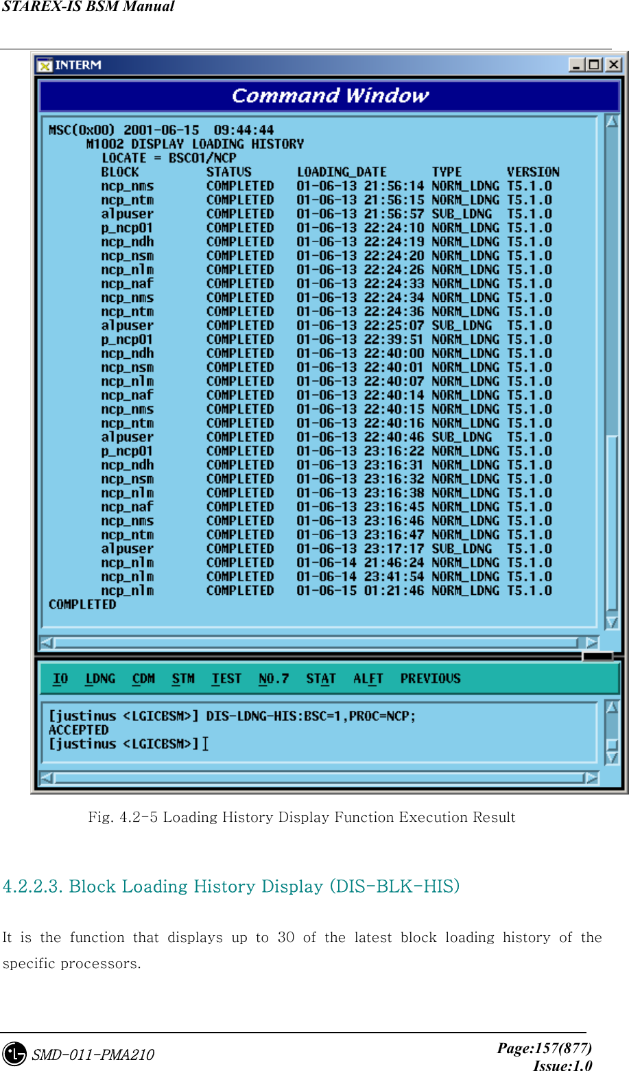
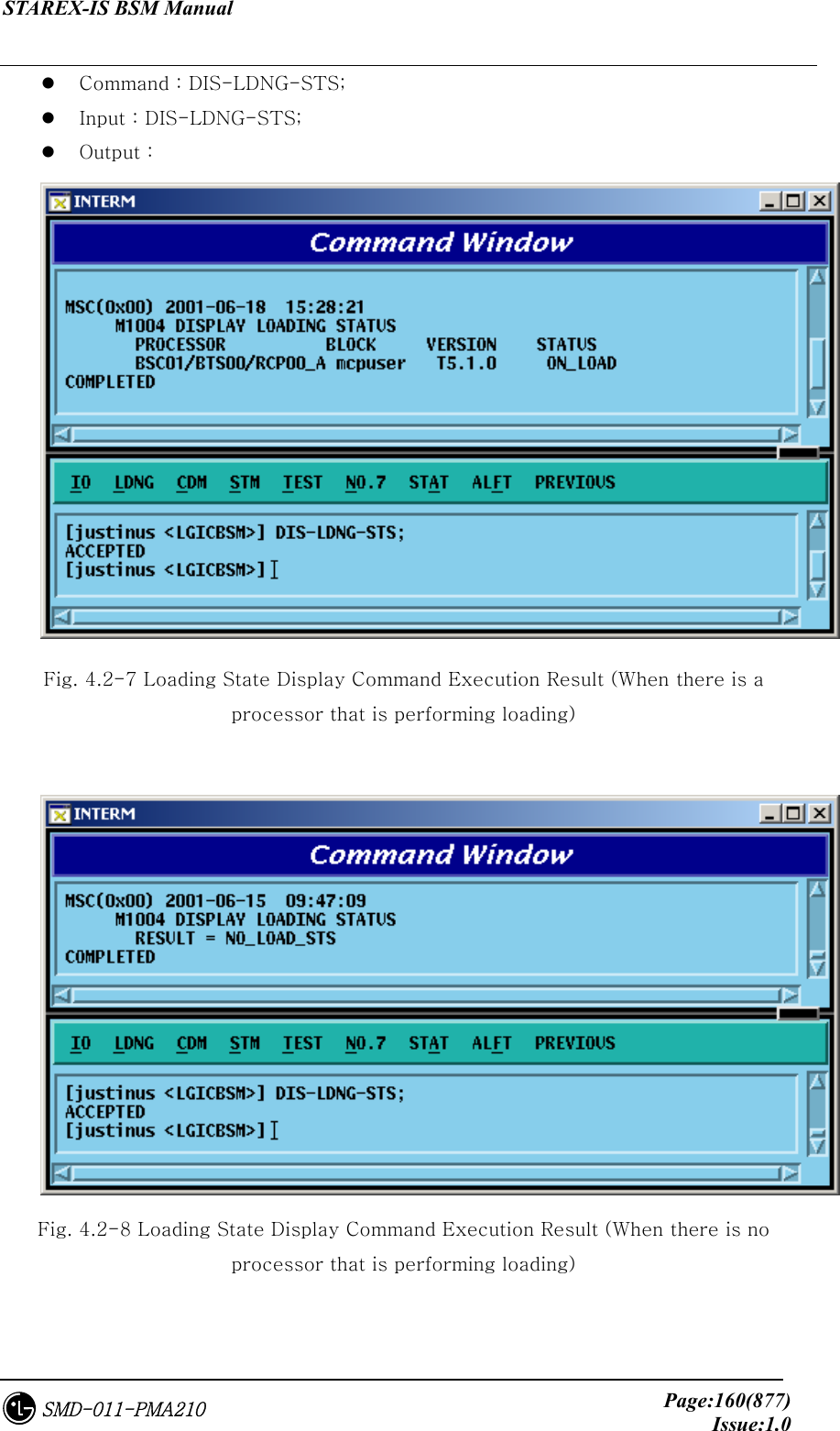
![STAREX-IS BSM Manual Page:156(877)Issue:1.0SMD-011-PMA210 Command : DIS-LDNG-HIS:[BSC=a,][BTS=b,][PROC=c] ; a : BSC ID [ Number 0~11 ] b : BTS ID [ Number 0~47 ] c : Processor Name (When deleting processor names, the entire processors are displayed) [ CNP, PNP, PCP0, PCP1, PCP2, PMP0, PMP1, PMP2, NCP, CCP, SCP, BSP, ALP, SMP0, SMP1, SMP2, SMP3, SMP4, VMP0, VMP1, VMP2, VMP3, VMP4, VMP5, VMP6, VMP7, RCP0, RCP1, RCP2, RCP3, RCP4, RCP5, RCP6, RCP7, RCP8, RCP9 ] Input : DIS-LDNG-INFO:BSC=1,PROC=NCP; Output :](https://usermanual.wiki/LG-Electronics-USA/3G1XINBTS.Users-Manual-Part-A/User-Guide-178301-Page-157.png)
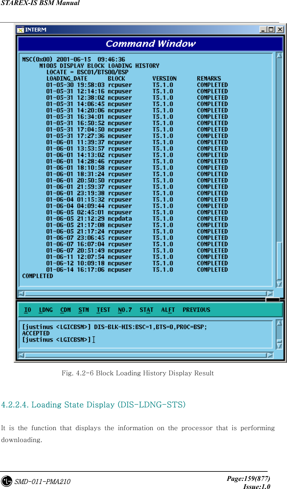
![STAREX-IS BSM Manual Page:158(877)Issue:1.0SMD-011-PMA210 Command : DIS-BLK-HIS:[BSC=a,][BTS=b,]PROC=c ; a : BSC ID [ Number 0~11 ] b : BTS ID [ Number 0~47 ] c : Processor Name [ CNP, PNP, PCP0, PCP1, PCP2, PMP0, PMP1, PMP2, NCP, CCP, SCP, BSP, SMP0, SMP1, SMP2, SMP3, SMP4, VMP0, VMP1, VMP2,VMP3,VMP4,VMP5,VMP6,VMP7 ] Input : DIS-LDNG-INFO:BSC=1,BTS=0,PROC=BSP; Output :](https://usermanual.wiki/LG-Electronics-USA/3G1XINBTS.Users-Manual-Part-A/User-Guide-178301-Page-159.png)
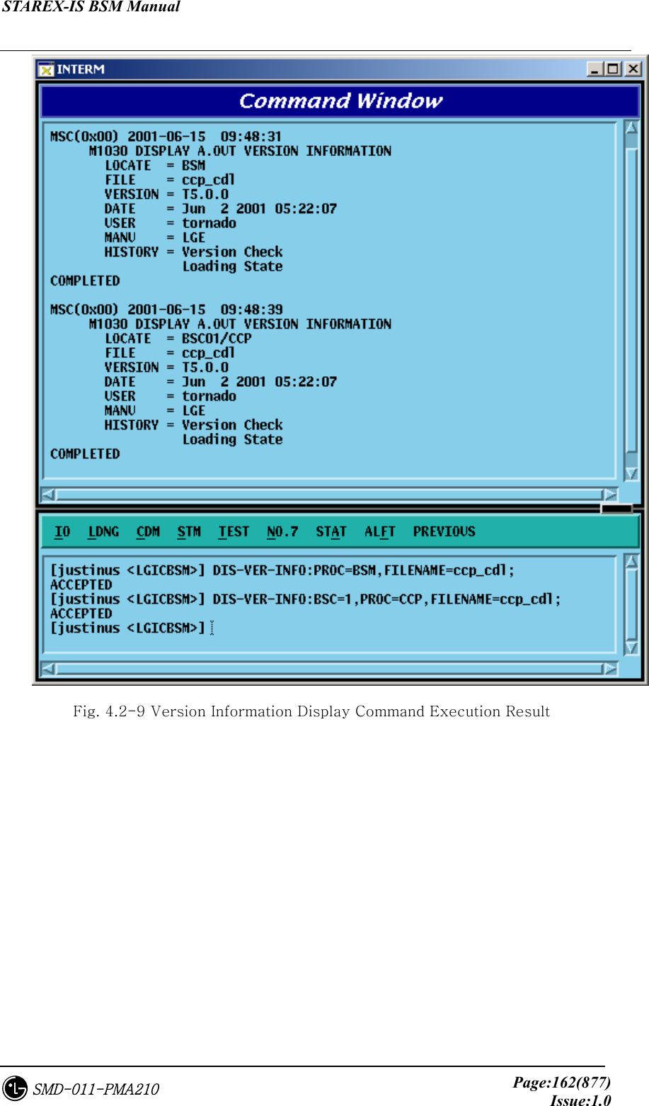
![STAREX-IS BSM Manual Page:161(877)Issue:1.0SMD-011-PMA210 4.2.2.5. a.out Version Information Display (DIS-VER-INFO) The command to display a.out version information is used to check the S/W block version that is downloaded from the BSM loading directory or target processor. The target processors that can designate are as follows: BSM, CNP, PNP, PCP, PMP, NCP, CCP, SCP, BSP, ALP, SMP, VMP, and RCP. Command : DIS-VER-INFO:[BSC=a,][BTS=b,]PROC=c[,FILENAME=d]; a : BSC ID [ Number 0~11 ] b : BTS ID [ Number 0~47 ] c : Processor Name [ BSM,CNP,PNP,PCP0,PCP1,PCP2,PMP0, PMP1, PMP2, NCP, CCP, SCP, BSP, ALP, SMP0, SMP1, SMP2, SMP3, SMP4, VMP0, VMP1, VMP2, VMP3, VMP4, VMP5, VMP6, VMP7, RCP0, RCP1, RCP2, RCP3, RCP4, RCP5, RCP6, RCP7, RCP8, RCP9 ] d : File Name [ String ] Input : DIS-VER-INFO:PROC=BSM,FILENAME=ccp_cdl; DIS-VER-INFO:BSC=1,PROC=CCP,FILENAME=ccp_cdl; Output :](https://usermanual.wiki/LG-Electronics-USA/3G1XINBTS.Users-Manual-Part-A/User-Guide-178301-Page-162.png)
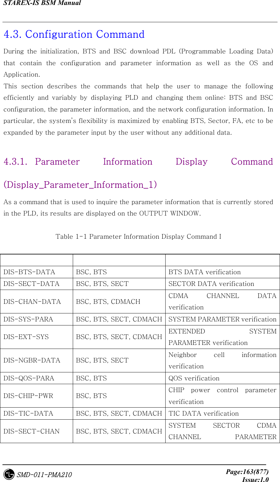
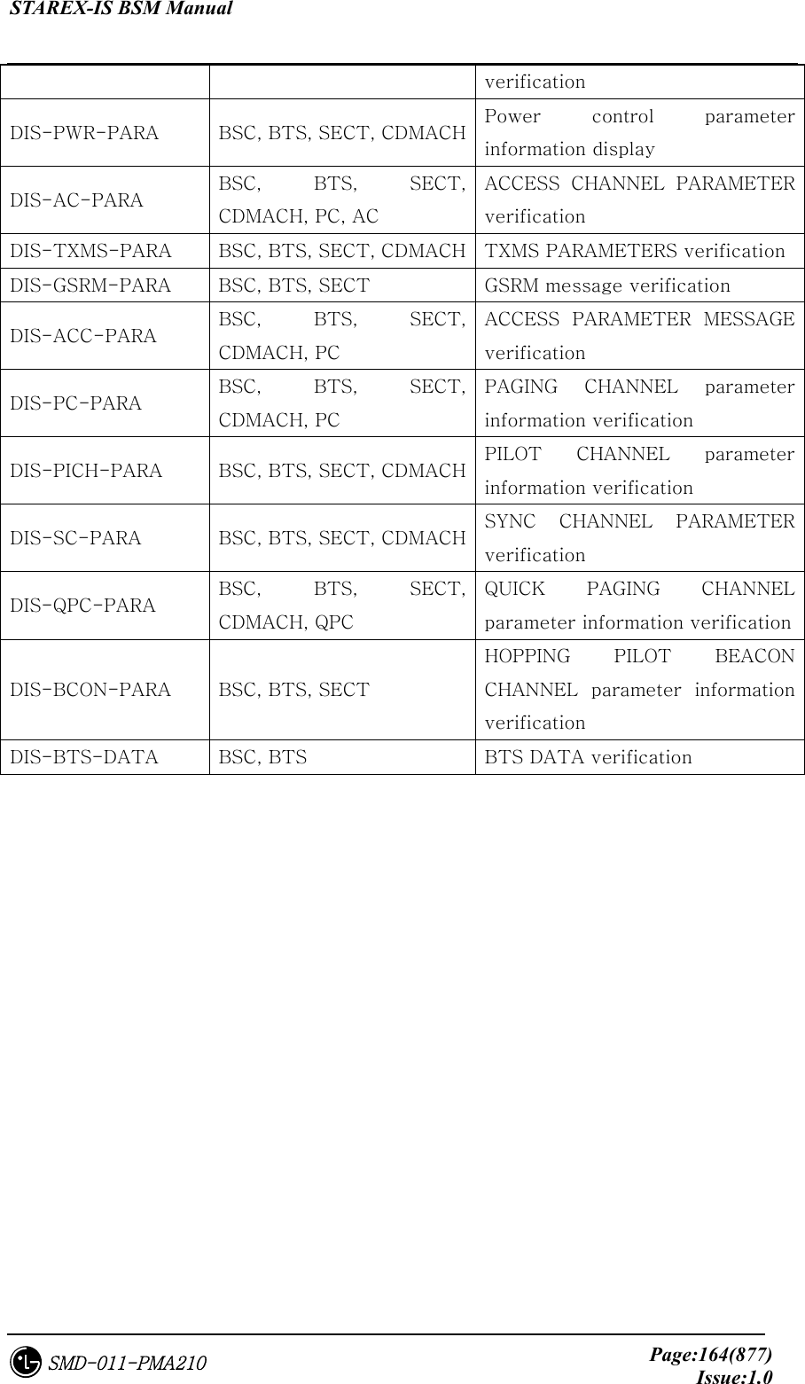
![STAREX-IS BSM Manual Page:166(877)Issue:1.0SMD-011-PMA210 4.3.1.2. Sector Parameter Information Display The BTS can be divided into 1~3 sectors to accommodate more subscribers. The sector parameter information is composed of the information on each sector in BTS and both BTS and BSC refer to this information. The user can inquire the data by BTS Group, BTS Sub, and sector. • Command DIS-SECT-DATA:BSC=a[,BTS_GRP=b][,BTS_SUB=c][,SECT=d]; a : BSC Number (0 ~ 11) b : BTS Number (0 ~ 47) c : BTS Sub Number (0 ~ 3) d : Sector Number (ALPHA/BETA/GAMMA) • Input DIS-SECT-DATA:BSC=0,BTS=0,SECT=ALPHA; • Output Fig. 4.3-2 Sector Parameter Information Display](https://usermanual.wiki/LG-Electronics-USA/3G1XINBTS.Users-Manual-Part-A/User-Guide-178301-Page-167.png)
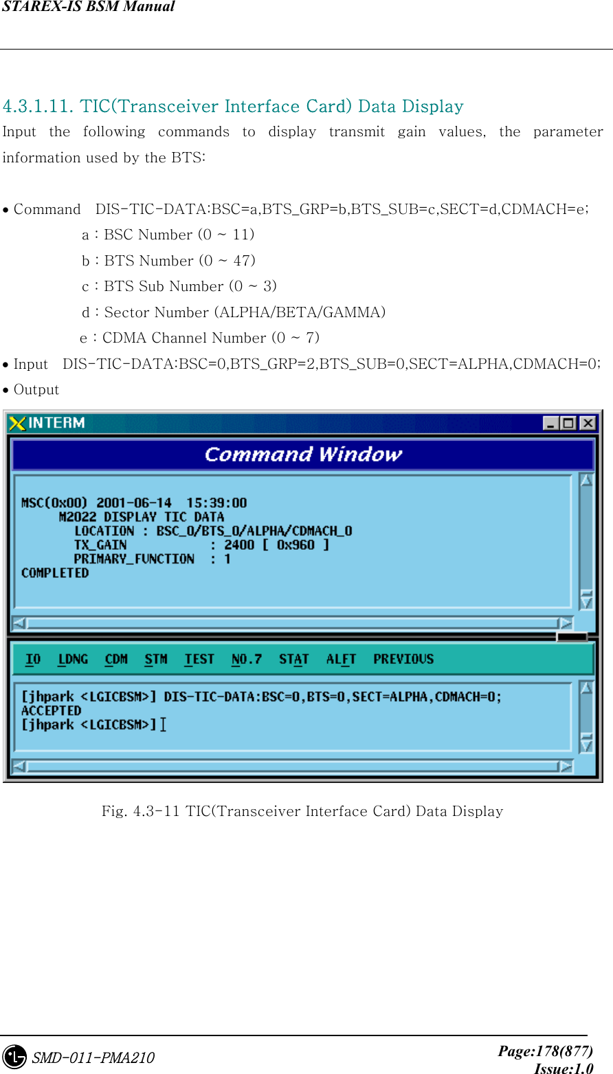
![STAREX-IS BSM Manual Page:167(877)Issue:1.0SMD-011-PMA210 4.3.1.3. CDMA Channel Parameter Information Display The following command is used to display parameter information such as bandwidth of each CDMA channel, CDMA channel number, spare channel rate for Handoff(or Handover). This information is referred by both BTS and BSC. • Command DIS-CHAN-DATA:BSC=a,BTS_GRP=b,BTS_SUB=c[,CDMACH=c]; a : BSC Number (0 ~ 11) b : BTS Number (0 ~ 47) c : BTS Sub Number(0 ~ 3) d : CDMA Channel Number (0 ~ 7) • Input DIS-CHAN-DATA:BSC=0,BTS_GRP=2,BTS_SUB=0; • Output Fig. 4.3-3 CDMA Channel Parameter Information Display](https://usermanual.wiki/LG-Electronics-USA/3G1XINBTS.Users-Manual-Part-A/User-Guide-178301-Page-168.png)
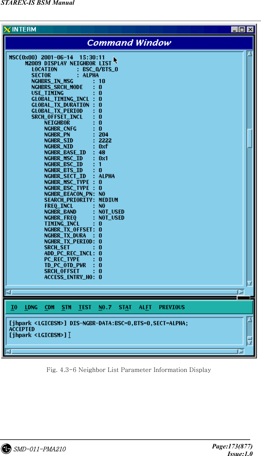
![STAREX-IS BSM Manual Page:172(877)Issue:1.0SMD-011-PMA210 4.3.1.6. Neighbor List Parameter Information Display Neighbor list refers to a set of the information on neighbor sectors. Each sector can have up to 20 neighbor lists. When the MS, which is busy or idle, moves to other sectors, it has to switch over a call (this is called Handoff or Handover). At this time, handoff is carried out in reference to the neighbor list. The neighbor list is referred by BTS and BSC and can be inquired by using the following command: • Command DIS-NGBR-DATA:BSC=aa,BTS_GRP=b[,BTS_SUB=c][,SECT=c]; a : BSC Number (0 ~ 11) b : BTS Number (0 ~ 47) c : BTS Sub Number (0 ~ 3) d : Sector Number (ALPHA/BETA/GAMMA) • Input DIS-NGBR-DATA:BSC=0,BTS_GROUP=2,BTS_SUB=0; • Output](https://usermanual.wiki/LG-Electronics-USA/3G1XINBTS.Users-Manual-Part-A/User-Guide-178301-Page-173.png)