LG Electronics USA 3G1XINBTS STAREX-IS 1900 Indoor BTS User Manual STAREX IS User s Manual
LG Electronics USA STAREX-IS 1900 Indoor BTS STAREX IS User s Manual
UserManual.wiki
>
LG Electronics USA
>
3G1XINBTS User Manual
>
Users Manual Part B
Contents
1.
Users Manual Part A
2.
Users Manual Part B
3.
Users Manual Part C
4.
Users Manual Part D
5.
Users Manual Part E
6.
Users Manual Part F
7.
Users Manual Part G
Users Manual Part B
Navigation menu
Upload a User Manual
Namespaces
Wiki Guide
HTML
PDF
Info
Views
User Manual
Discussion / Help
Navigation
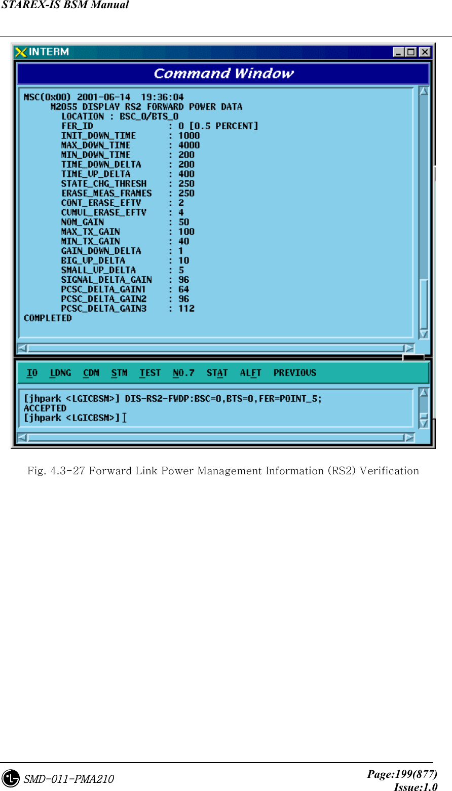

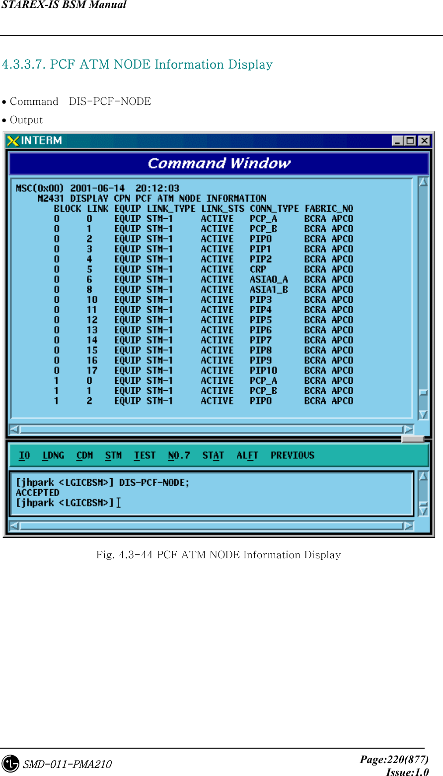
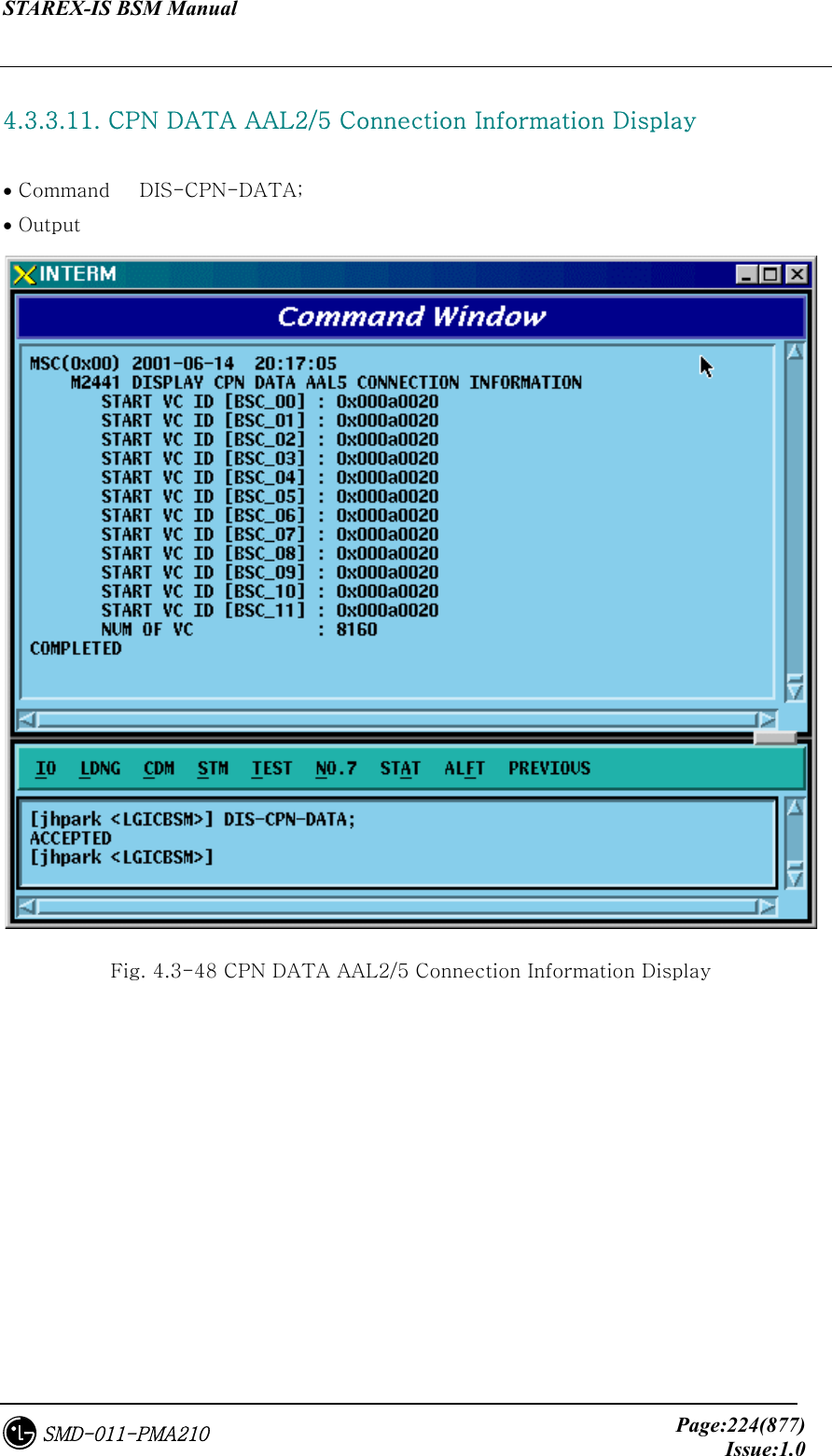
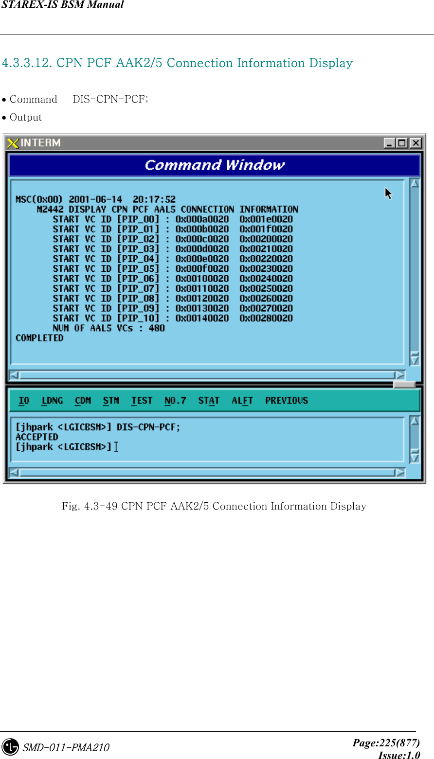
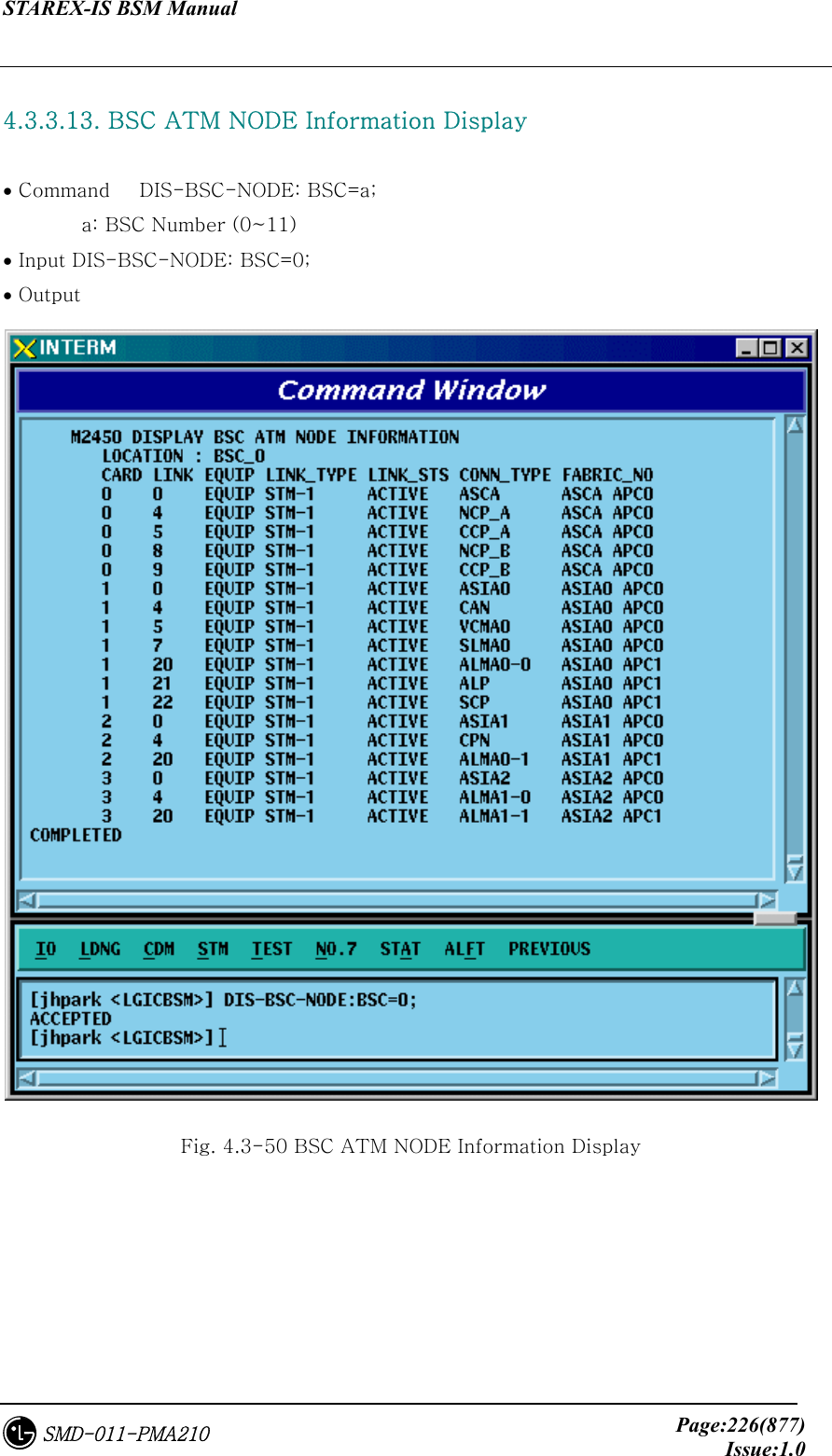
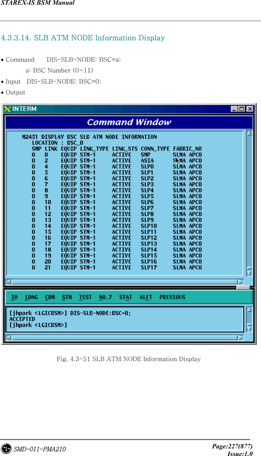

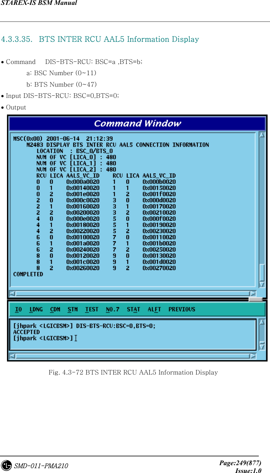
![STAREX-IS BSM Manual Page:252(877)Issue:1.0SMD-011-PMA210 4.3.4.1. BTS Parameter Information Change To change the BTS parameter information, click CDM->Change_Parameter_ Information->Change BTS Data on the Command Window in order and input the value that the command wants to change in each field. • Command CHG-BTS-DATA :BSC=a ,BTS=b [,SID=c] [,NID=d] [,BASE_ID=e] [,BASE_CLASS=f] [,REG_ZONE=g] [,LTM_OFF=h] [,DAY_LT=i] [,BASE_LAT=j] [,BASE_LONG=k] [,TUB_ENC=l] [,REV_PWR=m]; • Input CHG-BTS-DATA :BSC=0 ,BTS=0 ,SID=3333; • Output](https://usermanual.wiki/LG-Electronics-USA/3G1XINBTS.Users-Manual-Part-B/User-Guide-178302-Page-54.png)
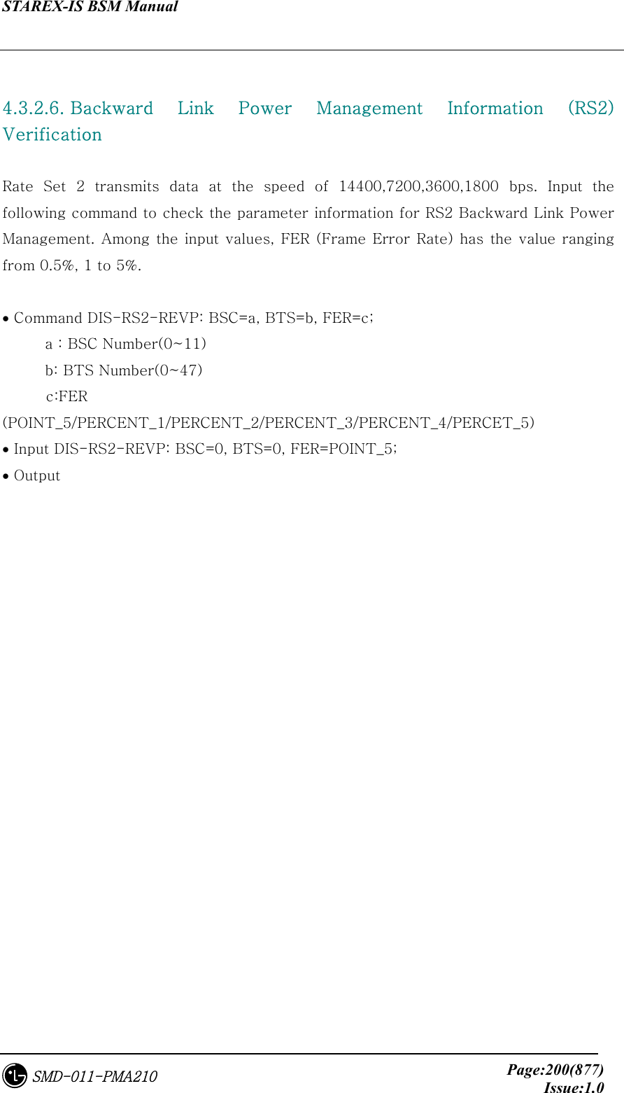
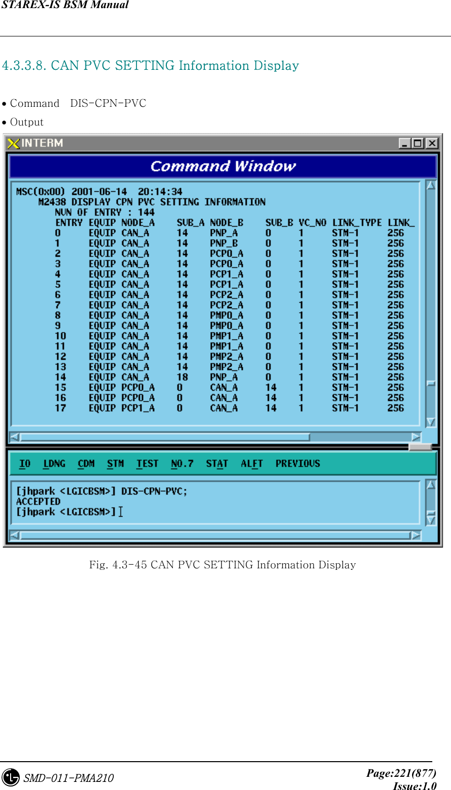
![STAREX-IS BSM Manual Page:253(877)Issue:1.0SMD-011-PMA210 Fig. 4.3-73 BTS Parameter Information Display 4.3.4.2. Sector Parameter Information Change To change the sector parameter information, click CDM->Change_Parameter_ Information_1-> CHG-SECT-DATA on the Command Window in order. If the next input window is displayed, then input the value to be changed. • Command CHG-SECT-DATA :BSC=a ,BTS=b ,SECT=c [,PN=d] [,CNTL_PARA=e] ; • Input CHG-SECT-DATA :BSC=0 ,BTS=0 ,SECT=ALPHA ,PN=40; • Output Fig. 4.3-74 Sector Parameter Information Change](https://usermanual.wiki/LG-Electronics-USA/3G1XINBTS.Users-Manual-Part-B/User-Guide-178302-Page-55.png)
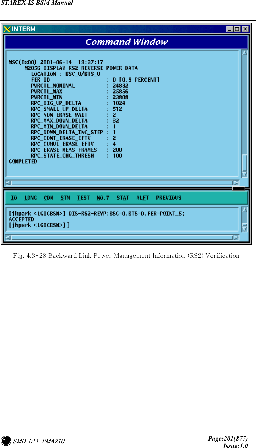
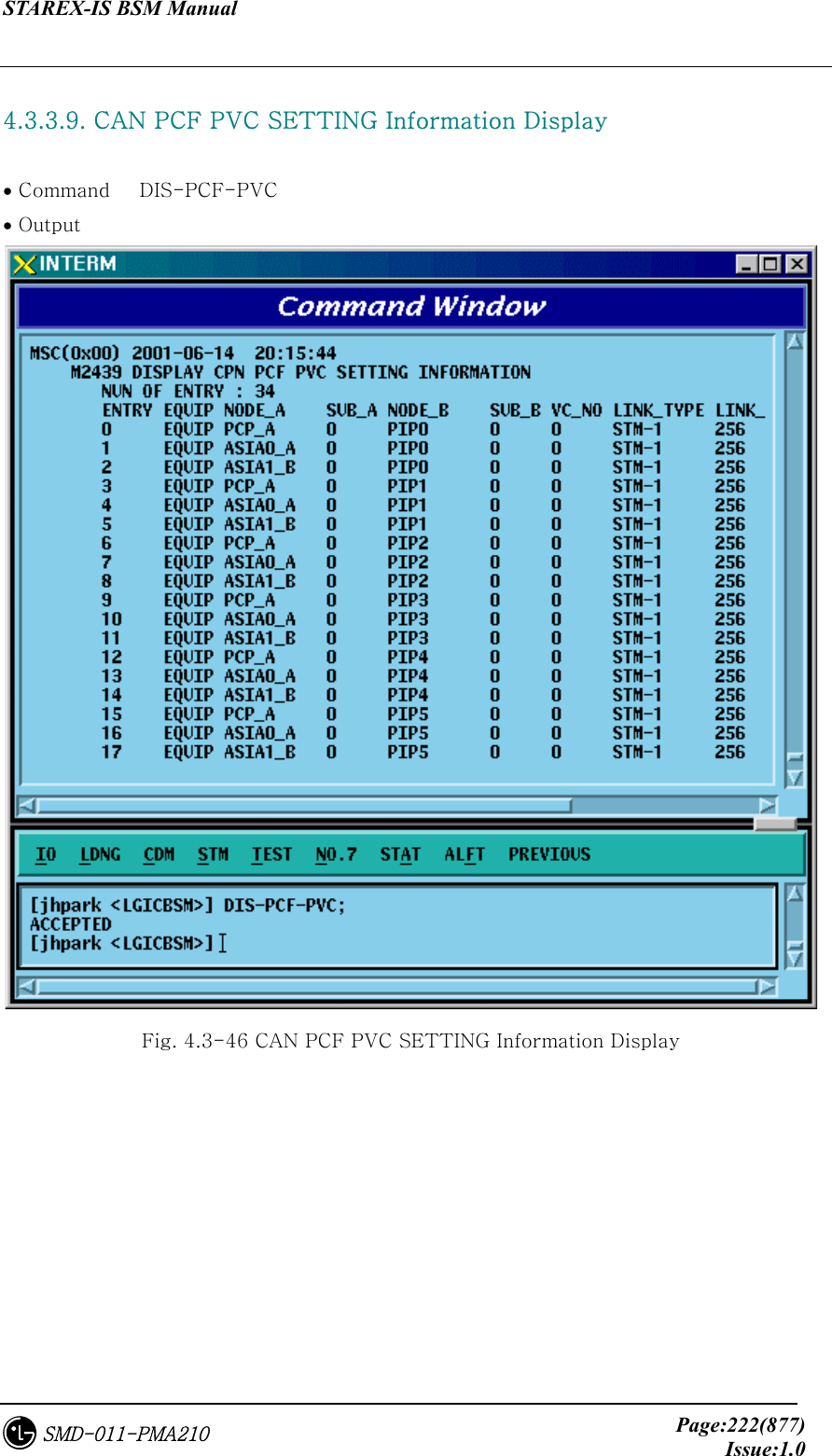
![STAREX-IS BSM Manual Page:254(877)Issue:1.0SMD-011-PMA210 4.3.4.3. CDMA Channel Parameter Information Change To change the CDMA parameter information, click CDM->Change_Parameter_ Information_1-> CHG-CHAN-DATA on the Command Window in order. If the next input window is displayed, then input the value to be changed. • Command CHG-CHAN-DATA :BSC=a ,BTS=b ,CDMACH=c [,FREQ_BAND=d] [,CH_NUM=e] [,TCE_4HO=f] [,MAX_SCH=g]; • Input CHG-CHAN-DATA :BSC=0,BTS=0 ,CDMACH=0 ,FREQ_BAND=2222; • Output Fig. 4.3-75 CDMA Channel Parameter Information Display](https://usermanual.wiki/LG-Electronics-USA/3G1XINBTS.Users-Manual-Part-B/User-Guide-178302-Page-56.png)
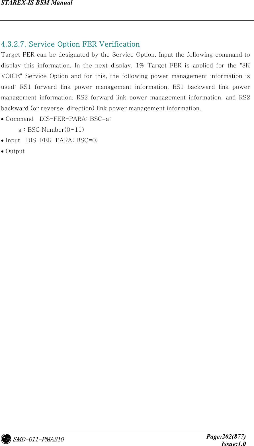
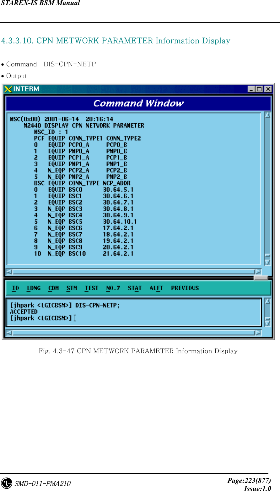
![STAREX-IS BSM Manual Page:255(877)Issue:1.0SMD-011-PMA210 4.3.4.4. SYSTEM PARAMETER(1) Change To change the system parameter message, click CDM-> Change_Parameter_Information_1-> CHG-SYS1-PARA on the Command Window in order. As the System Parameter Message have many elements, they are divided into the three commands. The output format for each command is the same. • Command CHG-SYS1-PARA :BSC=a ,BTS=b ,SECT=c ,CDMACH=d [,TOT_ZONE=e] [,ZONE_TIME=f] [,MULT_SIDS=g] [,MULT_NIDS=h] [,REP_THSH=i] [,REP_FRAM=j] [,SRCH_WINA=k] [,SRCH_WINN=l] [,SRCH_WINR=m] [,NGHB_MAGE=n] [,T_ADD=o] [,T_DROP=p] [,T_COMP=q] [,T_TDRP=r]; • Input CHG-SYS1-PARA :BSC=0,BTS=0 ,SECT=ALPHA,CDMACH=0,TOT_ZONE=5 • Output](https://usermanual.wiki/LG-Electronics-USA/3G1XINBTS.Users-Manual-Part-B/User-Guide-178302-Page-57.png)
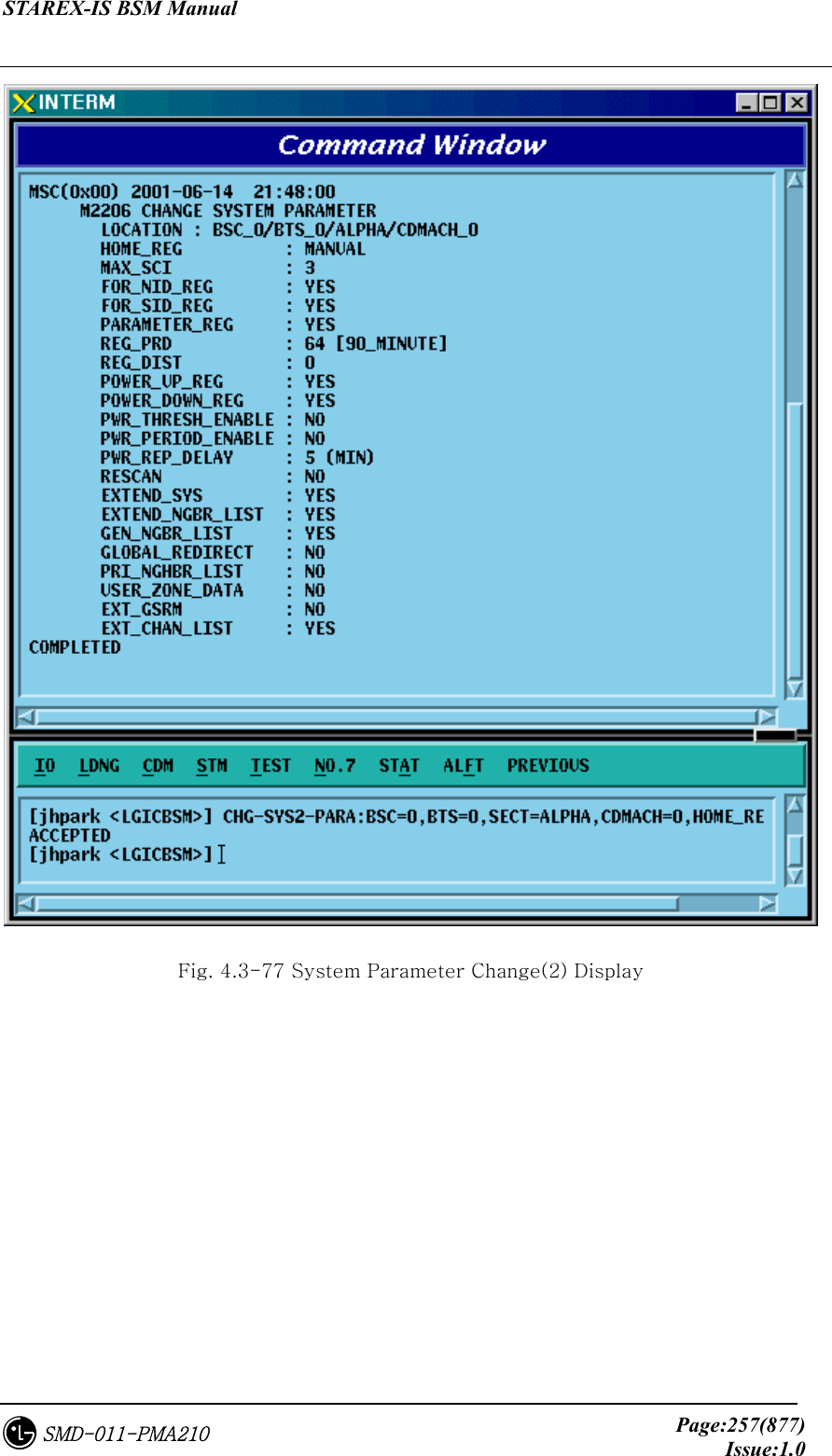
![STAREX-IS BSM Manual Page:256(877)Issue:1.0SMD-011-PMA210 Fig. 4.3-76 System Parameter Change(1) Display 4.3.4.5. SYSTEM 4.3.4.6. PARAMETER(2) Change To change the system parameter message, click CDM-> Change_Parameter_Information_1-> CHG-SYS2-PARA on the Command Window in order. Since the System Parameter Message have many elements, they are divided into three commands. The output format for each command is the same. • Input CHG-SYS2-PARA :BSC=a ,BTS=b ,SECT=c ,CDMACH=d [,HOME_REG=e] [,MAX_SCI=f] [,NID_REG=g] [,SID_REG=h] [,PARM_REG=i] [,REG_PRD=j] [,REG_DIST=k] [,PWR_UP=l] [,PWR_DOWN=m] [,THSH_EABL=n] [,PRID_EABL=o] [,REP_DELY=p] [,RE_SCAN=q] [,EXT_SYS=r] [,EXT_NGHBR=s] [,GEN_NGHBR=t] [,REDIRECT=u] [,PRI_NGHBR=v] [,USER_ZONE=w] [,EXT_REDIRECT=x] [,EXT_CHAN=y] ; • Output CHG-SYS2-PARA :BSC=0 ,BTS=0,SECT=ALPHA ,CDMACH=0, HOME_REG=MANUAL; • Display](https://usermanual.wiki/LG-Electronics-USA/3G1XINBTS.Users-Manual-Part-B/User-Guide-178302-Page-58.png)
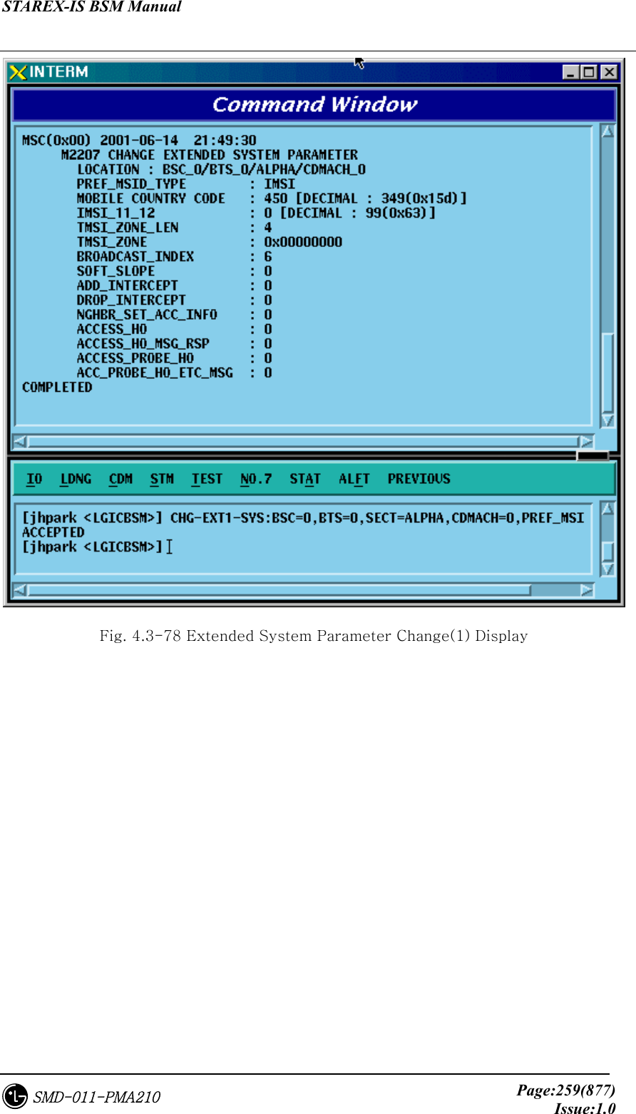
![STAREX-IS BSM Manual Page:258(877)Issue:1.0SMD-011-PMA210 4.3.4.7. EXTENDED SYSTEM PARAMETER(1) Change To change the Extended System Parameter Message, click CDM-> Change_Parameter_Information_1-> CHG-EXT1-SYS on the Command Window in order. If the next input window is displayed, then input the value to be changed. • Change CHG-EXT1-SYS :BSC=a ,BTS=b ,SECT=c ,CDMACH=d [,PREF_MSID=e] [,MCC=f] [,IMSI_11_12=g] [,TMSI_LEN=h] [,TMSI_ZONE_1=i] [,TMSI_ZONE_2=j] [,TMSI_ZONE_3=k] [,TMSI_ZONE_4=l] [,TMSI_ZONE_5=m] [,TMSI_ZONE_6=n] [,TMSI_ZONE_7=o] [,TMSI_ZONE_8=p] [,BCAST_IDX=q] [,SOFT_SLOPE=r] [,ADD_INT=s] [,DROP_INT=t] [,NGBR_SET=u] [,ACCESS_HO=v] [,HO_MSG_RSP=w] [,ACC_PRB_HO=x] [,PRB_HO_OT=y] ; • Input CHG-EXT1-SYS :BSC=0 ,BTS=0 ,SECT=ALPHA ,CDMACH=0 , PREF_MSID=IMSI; • Output](https://usermanual.wiki/LG-Electronics-USA/3G1XINBTS.Users-Manual-Part-B/User-Guide-178302-Page-60.png)
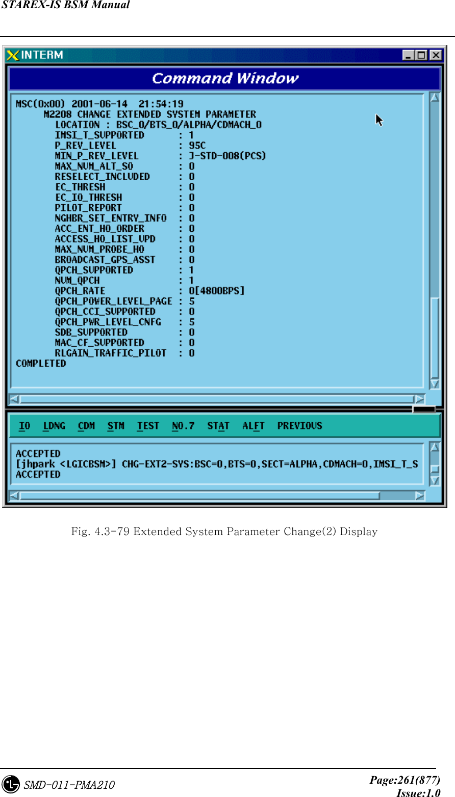
![STAREX-IS BSM Manual Page:260(877)Issue:1.0SMD-011-PMA210 4.3.4.8. EXTENDED SYSTEM PARAMETER(2) Change To change the Extended System Parameter Message, click CDM-> Change_Parameter_Information_1-> CHG-EXT2-SYS on the Command Window in order. If the next input window is displayed, then input the value to be changed. • Command CHG-EXT2-SYS :BSC=a ,BTS=b ,SECT=c ,CDMACH=d [,IMSI_T_SUPRT=e] [,P_REV=f] [,MIN_P_REV=g] [,MAX_ALT_SO=h] [,RESEL_INCL=i] [,EC_THRESH=j] [,EC_IO_THRESH=k] [,PILOT_REPORT=l] [,NGBR_SET_INF=m] [,ACC_HO_ORD=n] [,HO_LIST_UPD=o] [,MAX_PRB_HO=p] [,BRD_GPS_ASS=q] [,QPC_SUPPORT=r] [,NUM_QPCH=s] [,QPCH_RATE=t] [,QPC_PWR_LEV=u] [,QPC_CCI=v] [,QPC_PWR_CFG=w] [,SDB_SUPPORT=x] [,MAC_CF_SPRT=y] [,RLGAIN_PICH=z]; • Input CHG-EXT2-SYS :BSC=0 ,BTS=0,SECT=ALPHA ,CDMACH=,IMSI_T_SUPRT=1; • Output](https://usermanual.wiki/LG-Electronics-USA/3G1XINBTS.Users-Manual-Part-B/User-Guide-178302-Page-62.png)
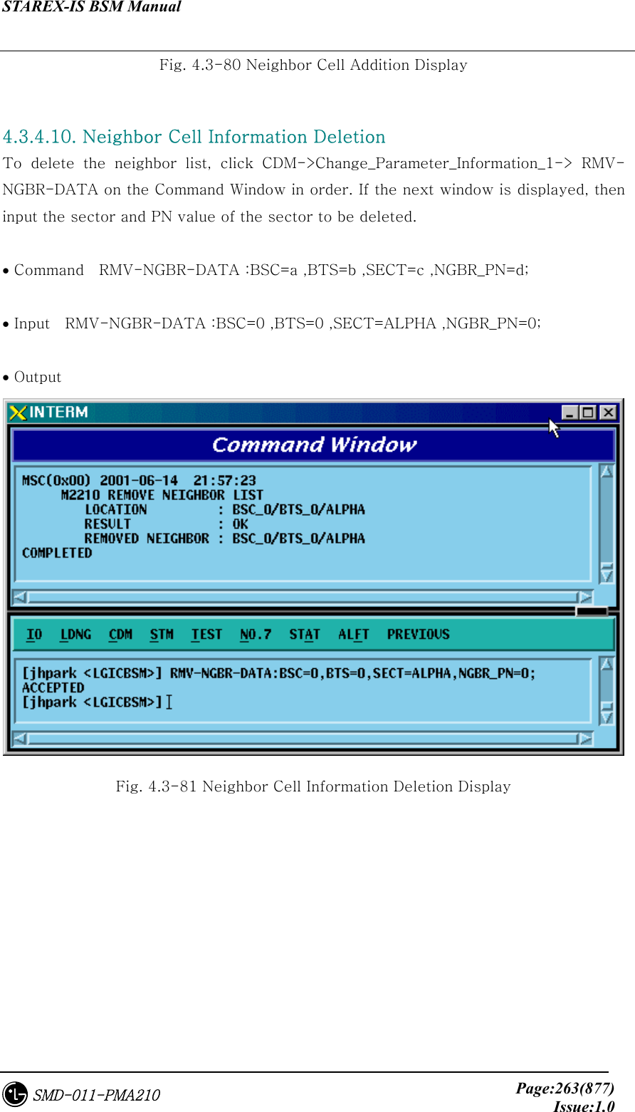
![STAREX-IS BSM Manual Page:262(877)Issue:1.0SMD-011-PMA210 4.3.4.9. Neighbor Cell Information Addition To add the neighbor list, click the CDM->Change_Parameter_Information_1-> ADD-NGBR-DATA on the Command Window in order. If the next input window is displayed, then input the values to be changed. • Command ADD-NGBR-DATA :BSC=a ,BTS=b ,SECT=c ,INDEX=d ,NGBR_CNFG=e ,NGBR_PN=f ,NGBR_SID=g ,NGBR_NID=h ,NGBR_BASE=i ,NGBR_MSC=j ,NGBR_BSC=k ,NGBR_BTS=l ,NGBR_SECT=m ,NGBR_MSC_T=n ,NGBR_BSC_T=o,NGBR_BCON=p ,SRCH_PRIO=q ,FREQ_INCL=r [,NGBR_BAND=s] [,NGBR_FREQ=t] [,TIME_INCL=u] [,TX_OFFSET=v] [,TX_DURATION=w] [,TX_PERIOD=x] [,SRCH_SET=y] [,ADD_PICH_REC=z] [,PICH_REC=] [,OTD_PWR=] [,SRCH_OFFSET=] [,ACC_HO=] [,ACC_HO_ALW=]; • Input ADD-NGBR-DATA :BSC=0 ,BTS=0 ,SECT=ALPHA ,INDEX=0 ,NGBR_CNFG=0 ,NGBR_PN=0 ,NGBR_SID=0 ,NGBR_NID=0 ,NGBR_BASE=0 ,NGBR_MSC=0 ,NGBR_BSC=0 ,NGBR_BTS=0 ,NGBR_SECT=ALPHA ,NGBR_MSC_T=LG_MSC ,NGBR_BSC_T=LG_BSC,NGBR_BCON=NO ,SRCH_PRIO=LOW ,FREQ_INCL=NO,NGBR_BAND=Mhz_800; • Output](https://usermanual.wiki/LG-Electronics-USA/3G1XINBTS.Users-Manual-Part-B/User-Guide-178302-Page-64.png)
![STAREX-IS BSM Manual Page:265(877)Issue:1.0SMD-011-PMA210 4.3.4.12. HOPPING BEACON PARAMETER Change To change Hopping Beacon Parameter, click CDM->Change_Parameter_Information_1-> CHG-NGBR-BCON on the Command Window in order. • Command CHG-NGBR-BCON :BSC=a ,BTS=b ,SECT=c ,CDMACH=d [,NGBR_SRCH=e] [,USE_TIMING=f] [,G_TIME_INCL=g] [,G_TX_DURATE=h] [,G_TX_PERIOD=i] [,SRCH_OFF_INC=j] ; • Input CHG-NGBR-BCON :BSC=0 ,BTS=0 ,SECT=ALPHA ,CDMACH=0 , NGBR_SRCH=255; • Output Fig. 4.3-82 Hopping Beacon Parameter Change Display](https://usermanual.wiki/LG-Electronics-USA/3G1XINBTS.Users-Manual-Part-B/User-Guide-178302-Page-67.png)
![STAREX-IS BSM Manual Page:266(877)Issue:1.0SMD-011-PMA210 4.3.4.13. QOS Parameter Change To change Quality Of Service parameter information, click CDM->Change_Parameter_Information_1-> CHG-QOS-PARA on the Command Window in order. • Command CHG-QOS-PARA :BSC=a ,BTS=b [,MAX_SCH_RATE=c]; • Input CHG-QOS-PARA :BSC=0 ,BTS=0,MAX_SCH_RATE=255; • Output Fig. 4.3-83 QOS Parameter Information Change Display](https://usermanual.wiki/LG-Electronics-USA/3G1XINBTS.Users-Manual-Part-B/User-Guide-178302-Page-68.png)
![STAREX-IS BSM Manual Page:267(877)Issue:1.0SMD-011-PMA210 4.3.4.14. Chip Power Control Information Change To change Chip Power Control information, click CDM->Change_Parameter_Information_1-> CHG-CHIP-PWR on the Command Window in order. • Command CHG-CHIP-PWR :BSC=a ,BTS=b [,CH_PWR0=c] [,CH_PWR1=d] [,CH_PWR2=e] [,CH_PWR3=f] [,MIN_GAIN0=g] [,MIN_GAIN1=h] [,MIN_GAIN2=i] [,MIN_GAIN3=j][,MAX_GAIN0=k] [,MAX_GAIN1=l] [,MAX_GAIN2=m] [,MAX_GAIN3=n] [,STEP_UP_SIZE=o] [,STEP_DN_SIZE=p] [,FPC_PUNC=q] [,RPC_PUNC=r] [,PWR_CNT_PNT=s] [,PWR_CNT_PTN=t] ; • Input CHG-CHIP-PWR :BSC=0 ,BTS=0 ,CH_PWR0=255; • Output](https://usermanual.wiki/LG-Electronics-USA/3G1XINBTS.Users-Manual-Part-B/User-Guide-178302-Page-69.png)
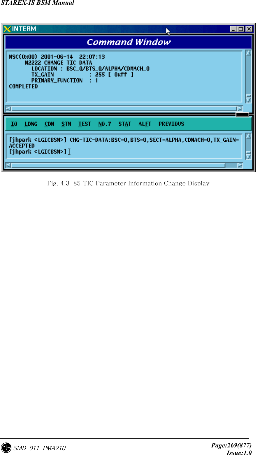
![STAREX-IS BSM Manual Page:268(877)Issue:1.0SMD-011-PMA210 Fig. 4.3-84 Chip Power Control Information Change Display 4.3.4.15. TIC Parameter Change To change Tx Gain value, click CDM->Change_ Parameter_Information_1-> CHG-TIC-DATA on the Command Window in order. If the next input window is displayed, then input the value to be changed. • Command CHG-TIC-DATA :BSC=a ,BTS=b ,SECT=c ,CDMACH=d [,TX_GAIN=e] ; • Input CHG-TIC-DATA :BSC=0 ,BTS=0 ,SECT=ALPHA ,CDMACH=0 ,TX_GAIN=255 ; • Output](https://usermanual.wiki/LG-Electronics-USA/3G1XINBTS.Users-Manual-Part-B/User-Guide-178302-Page-70.png)
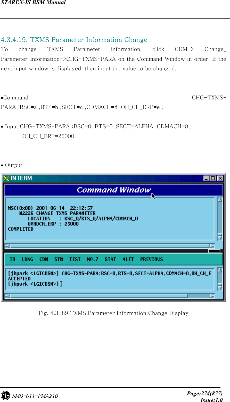
![STAREX-IS BSM Manual Page:270(877)Issue:1.0SMD-011-PMA210 4.3.4.16. OCNS Parameter Change To change OCNS Parameter value, click CDM->Change_ Parameter_Information_1-> CHG-OCNS-PARA on the Command Window in order. If the next input Window is displayed, then input the value to be changed. • Command CHG-OCNS-PARA :BSC=a ,BTS=b ,SECT=c ,CDMACH=d [,OCNS_ENABLE=e] [,NUM_OCNS_CH=f] [,OCNS_TEST=g] [,OCNS_SO=h]; • Input CHG-OCNS-PARA :BSC=0 ,BTS=0 ,SECT=ALPHA , CDMACH=0 ,OCNS_ENABLE=DISABLE,NUM_OCNS_CH=2; • Output Fig. 4.3-86 OCNS Parameter Change Display](https://usermanual.wiki/LG-Electronics-USA/3G1XINBTS.Users-Manual-Part-B/User-Guide-178302-Page-72.png)
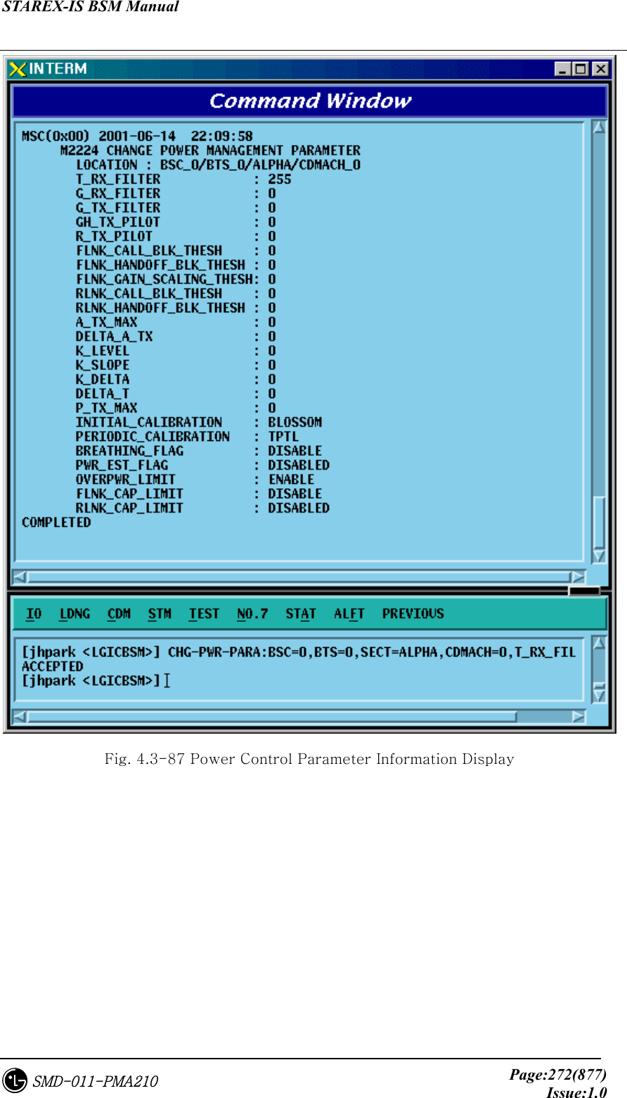
![STAREX-IS BSM Manual Page:271(877)Issue:1.0SMD-011-PMA210 4.3.4.17. Power Control Information Change To change OCNS Parameter value, click CDM->Change_ Parameter_Information_1-> CHG-PWR-PARA on the Command Window in order. If the next input Window is displayed, then input the value to be changed. • Command CHG-PWR-PARA :BSC=a ,BTS=b ,SECT=c ,CDMACH=d [,T_RX_FILTER=e] [,G_RX_FILTER=f] [,G_TX_FILTER=g] [,GH_TX_FILTER=h] [,R_TX_PILOT=i] [,FLN_BLK_THSH=j] [,FLN_HO_THSH=k] [,FLN_GAIN_SCA=l] [,RLN_BLK_THSH=m] [,RLNK_HO_THSH=n] [,A_TX_MAX=o] [,DELTA_A_TX=p] [,K_LEVEL=q] [,K_SLOPE=r] [,K_DELTA=s] [,DELTA_T=t] [,P_TX_MAX=u] [,INIT_CALB=v] [,PRD_CALIB=w] [,BREATH_FLAG=x] [,PWR_EST_FLAG=y] [,OVPWR_LMT=z] [,FLN_CAP_LMT=] [,RLN_CAP_LMT=]; • Input CHG-PWR-PARA :BSC=0 ,BTS=0 ,SECT=ALPHA ,CDMACH=0, T_RX_FILTER=255; • Output](https://usermanual.wiki/LG-Electronics-USA/3G1XINBTS.Users-Manual-Part-B/User-Guide-178302-Page-73.png)
![STAREX-IS BSM Manual Page:273(877)Issue:1.0SMD-011-PMA210 4.3.4.18. ACCESS CHANNEL Parameter Information Change To change Access Channel Parameter information, click CDM-> Change_ Parameter_Information->CHG-AC-PARA on the Command Window in order. If the next input window is displayed, then input the value to be changed. • Command CHG-AC-PARA :BSC=a ,BTS=b ,SECT=c ,CDMACH=d ,PC=e ,AC=f [,SRCH_OFFSET=g] [,SRCH_WIN_SZ=h]; • Input CHG-AC-PARA :BSC=0 ,BTS=0 ,SECT=ALPHA , CDMACH=0 , PC=0, SRCH_WIN_SZ=32; • Output Fig. 4.3-88 Access Channel Parameter Information Change Display](https://usermanual.wiki/LG-Electronics-USA/3G1XINBTS.Users-Manual-Part-B/User-Guide-178302-Page-75.png)
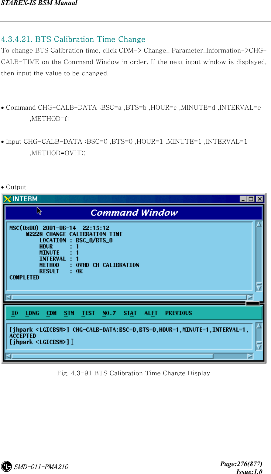
![STAREX-IS BSM Manual Page:275(877)Issue:1.0SMD-011-PMA210 4.3.4.20. BTS CALIBRATION Start To start BTS Calibration, click CDM-> Change_ Parameter_Information->START-BTS-CALB on the Command Window in order. If the next input window is displayed, then input the value to be changed. • Command START-BTS-CALB :BSC=a ,BTS=b [,SECT=c] [,CDMACH=d] ,METHOD=e ; • Input START-BTS-CALB :BSC=0 ,BTS=0 ,SECT=ALPHA,METHOD=OVHD ; • Output Fig. 4.3-90 BTS Calibration Start Display](https://usermanual.wiki/LG-Electronics-USA/3G1XINBTS.Users-Manual-Part-B/User-Guide-178302-Page-77.png)
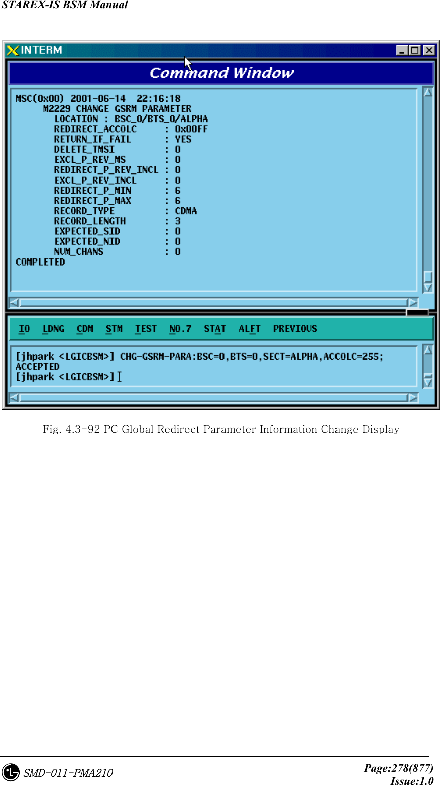
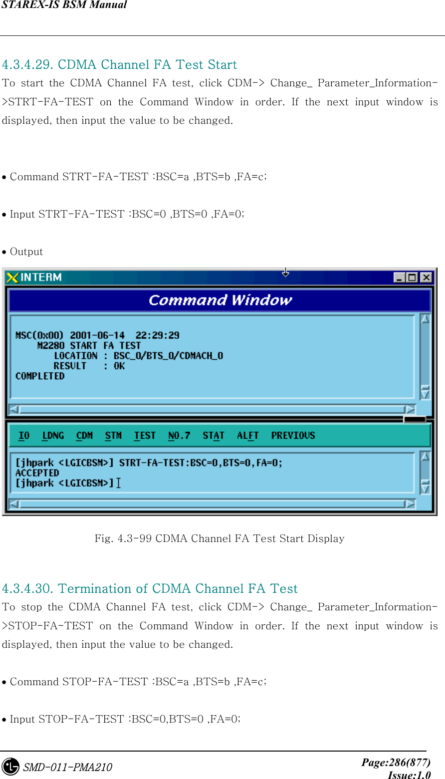
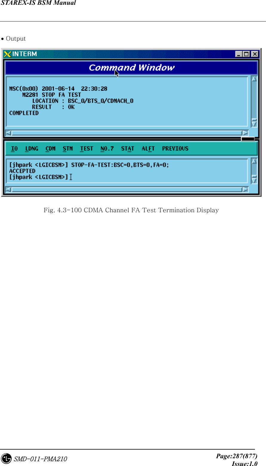
![STAREX-IS BSM Manual Page:277(877)Issue:1.0SMD-011-PMA210 4.3.4.22. PC GLOBAL REDIRECT Parameter Information Change To change Paging Channel Global Redirect information, click CDM-> Change_ Parameter_Information->CHG-GSRM-PARA on the Command Window in order. If the next input window is displayed, then input the value to be changed. • Command CHG-GSRM-PARA :BSC=a ,BTS=b ,SECT=c [,ACCOLC=d] [,RET_IF_FAIL=e] [,P_REV_MS=f] [,RDIR_P_REV=g] [,EXCL_P_REV=h] [,RDIR_P_MIN=i] [,RDIR_P_MAX=j] [,RECORD_TYPE=k] [,RECORD_LEN=l] [,EXPECT_A_SID=m] [,IGNORE_CDMA=n] [,SYS_ORDER=o] [,BAND_CLASS=p] [,EXPECT_SID=q] [,EXPECT_NID=r] [,NUM_CHAN=s] [,CDMA_CH_0=t] [,CDMA_CH_1=u] [,CDMA_CH_2=v] [,CDMA_CH_3=w] [,CDMA_CH_4=x] [,CDMA_CH_5=y] [,CDMA_CH_6=z] [,CDMA_CH_7=] [,CDMA_CH_8=] [,CDMA_CH_9=]; • Input CHG-GSRM-PARA :BSC=0 ,BTS=0 ,SECT=ALPHA,ACCOLC=255; • Output](https://usermanual.wiki/LG-Electronics-USA/3G1XINBTS.Users-Manual-Part-B/User-Guide-178302-Page-79.png)
![STAREX-IS BSM Manual Page:279(877)Issue:1.0SMD-011-PMA210 4.3.4.23. ACCESS PARAMETER Change To change Access Parameter information, click CDM-> Change_ Parameter_Information->CHG-ACC-PARA on the Command Window in order. If the next input window is displayed, then input the value to be changed. • Command CHG-ACC-PARA :BSC=a ,BTS=b ,SECT=c ,CDMACH=d ,PC=e [,NOM_PWR=f] [,INIT_PWR=g] [,PWR_STEP=h] [,NUM_STEP=i] [,MAX_CAP_SZ=j] [,PAM_SZ=k] [,PSST_09=l] [,PSST_10=m] [,PSST_11=n] [,PSST_12=o] [,PSST_13=p] [,PSST_14=q] [,PSST_15=r] [,MSG_PSST=s] [,REG_PSST=t] [,PRBE_RAN=u] [,ACC_TMO=v] [,PRBE_BKOF=w] [,BKOF=x] [,MREQ_SEQ=y] [,MRSP_SEQ=z] [,AUTH=] [,RAND=] [,NOM_PWR_EXT=]; • Input CHG-ACC-PARA :BSC=0 ,BTS=0,SECT=ALPHA ,CDMACH=0 ,PC=0 ,NOM_PWR=7; • Output](https://usermanual.wiki/LG-Electronics-USA/3G1XINBTS.Users-Manual-Part-B/User-Guide-178302-Page-81.png)

![STAREX-IS BSM Manual Page:281(877)Issue:1.0SMD-011-PMA210 4.3.4.24. PAGING CHANNEL Parameter Information Change To change Paging Channel Parameter information, click CDM-> Change_ Parameter_Information->CHG-PC-PARA on the Command Window in order. If the next input window is displayed, then input the value to be changed. • Command CHG-PC-PARA :BSC=a ,BTS=b ,SECT=c ,CDMACH=d ,PC=e [,PC_GAIN=f] [,FRM_DUR=g] [,DATA_RATE=h]; • Input CHG-PC-PARA :BSC=0 ,BTS=0 ,SECT=ALPHA ,CDMACH=0 ,PC=0 ,PC_GAIN=255; • Output Fig. 4.3-94 Paging Channel Parameter Information Display](https://usermanual.wiki/LG-Electronics-USA/3G1XINBTS.Users-Manual-Part-B/User-Guide-178302-Page-83.png)
![STAREX-IS BSM Manual Page:282(877)Issue:1.0SMD-011-PMA210 4.3.4.25. PILOT CHANNEL Parameter Information Change To change Pilot Channel Parameter information, click CDM-> Change_ Parameter_Information->CHG-PICH-PARA on the Command Window in order. If the next input window is displayed, then input the value to be changed. • Command CHG-PICH-PARA :BSC=a ,BTS=b ,SECT=c ,CDMACH=d [,PLOT_GAIN=e] [,PLOT_TD_GAIN=f]; • Input CHG-PICH-PARA :BSC=0 ,BTS=0 ,SECT=ALPHA , CDMACH=0,PLOT_GAIN=255; • Output Fig. 4.3-95 Pilot Channel Parameter Information Change Display](https://usermanual.wiki/LG-Electronics-USA/3G1XINBTS.Users-Manual-Part-B/User-Guide-178302-Page-84.png)
![STAREX-IS BSM Manual Page:283(877)Issue:1.0SMD-011-PMA210 4.3.4.26. SYNC CHANNEL Parameter Information Change To change Sync. Channel Parameter information, click CDM-> Change_ Parameter_Information->CHG-SC-PARA on the Command Window in order. If the next input window is displayed, then input the value to be changed. • Command CHG-SC-PARA :BSC=a ,BTS=b ,SECT=c ,CDMACH=d [,SC_GAIN=e]; • Input CHG-SC-PARA :BSC=0 ,BTS=b ,SECT=ALPHA ,CDMACH=0,SC_GAIN=255; • Output Fig. 4.3-96 Sync Channel Parameter Information Change Display](https://usermanual.wiki/LG-Electronics-USA/3G1XINBTS.Users-Manual-Part-B/User-Guide-178302-Page-85.png)
![STAREX-IS BSM Manual Page:284(877)Issue:1.0SMD-011-PMA210 4.3.4.27. QUICH PAGING CHANNEL Parameter Information Change To change Quick Paging Channel Parameter information, click CDM-> Change_ Parameter_Information->CHG-QPC-PARA on the Command Window in order. If the next input window is displayed, then input the value to be changed. • Command CHG-QPC-PARA :BSC=a ,BTS=b ,SECT=c ,CDMACH=d ,QPCH_ID=e [,FRAME_DUR=f] [,DATA_RATE=g]; • Input CHG-QPC-PARA :BSC=0 ,BTS=0 ,SECT=ALPHA ,CDMACH=0 ,QPCH_ID=0 ,FRAME_DUR=255; • Output Fig. 4.3-97 Quick Paging Channel Parameter Information Change Display](https://usermanual.wiki/LG-Electronics-USA/3G1XINBTS.Users-Manual-Part-B/User-Guide-178302-Page-86.png)
![STAREX-IS BSM Manual Page:285(877)Issue:1.0SMD-011-PMA210 4.3.4.28. HOPPING PILOT BEACON CHANNEL Parameter Information Change To change Hopping Pilot Beacon Channel Parameter information, click CDM-> Change_ Parameter_Information->CHG-BCON-PARA on the Command Window in order. If the next input window is displayed, then input the value to be changed. • Command CHG-BCON-PARA :BSC=a ,BTS=b ,SECT=c [,PILOT_GAIN=d] [,NUM_CDMA_CH=e] [,CDMA_FREQ1=f] [,CDMA_FREQ2=g] [,CDMA_FREQ3=h] [,CDMA_FREQ4=i] [,CDMA_FREQ5=j] [,CDMA_FREQ6=k] [,CDMA_FREQ7=l] [,CDMA_FREQ8=m] [,CDMA_FREQ9=n] [,CDMA_FREQ10=o] [,CDMA_FREQ11=p] [,CDMA_FREQ12=q]; • Input CHG-BCON-PARA :BSC=0 ,BTS=0 ,SECT=ALPHA ,PILOT_GAIN=255; • Output Fig. 4.3-98 Hopping Pilot Beacon Channel Parameter Information Change Display](https://usermanual.wiki/LG-Electronics-USA/3G1XINBTS.Users-Manual-Part-B/User-Guide-178302-Page-87.png)
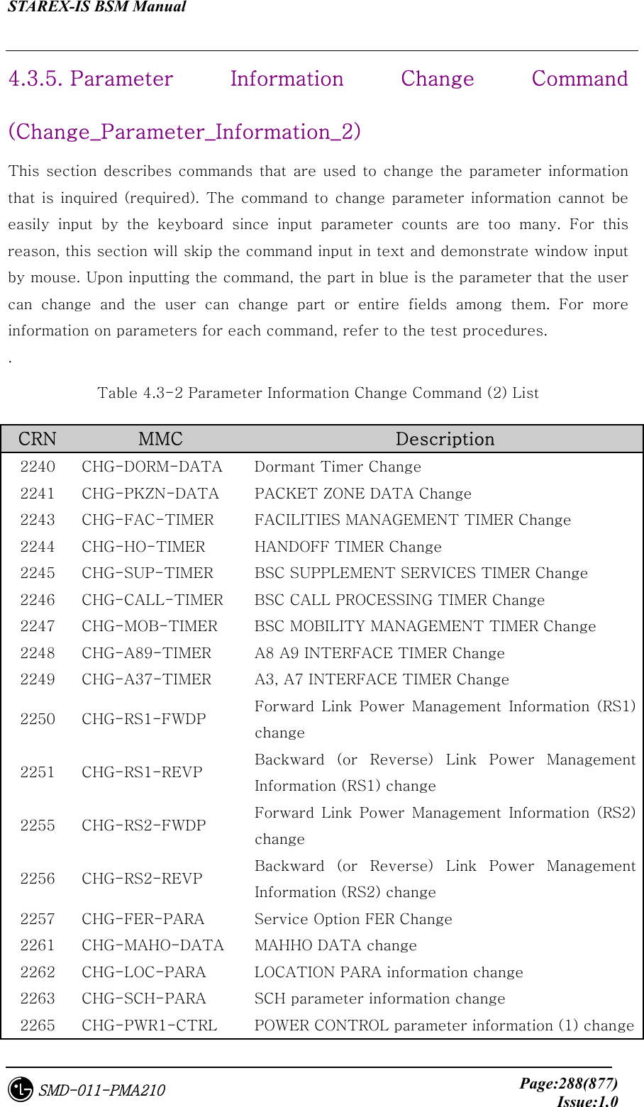
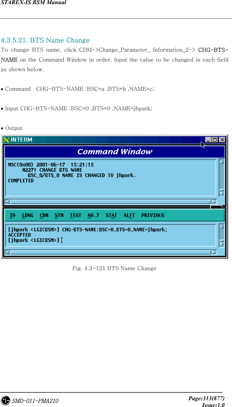
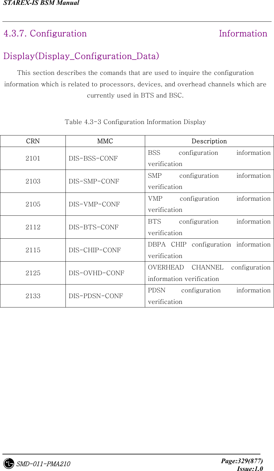
![STAREX-IS BSM Manual Page:289(877)Issue:1.0SMD-011-PMA210 2266 CHG-PWR2-CTRL POWER CONTROL parameter information (2) change 2267 CHG-PWR3-CTRL POWER CONTROL parameter information (3) change 2271 CHG-BTS-NAME BTS name change 2292 CHG-PCF-TIMER PCF TIMER change 2294 CHG-PCP-ADDR PCP/PMP ADDRESS change 2295 CHG-PIP-ADDR PIP ADDRESS change 2296 CHG-PCF-PARA PCF PARAMETER change 4.3.5.1. Dormant Timer Change To change Dormant Timer, click CDM->Change_Parameter_ Information_2-> CHG-DORM-DATA on the Command Window in order. Input the value to be changed in each field. • Command CHG-DORM-DATA :BSC=a [,DORMANT_T=b] [,INACTIVE_T=c] [,BAND_FRAME_T=d] [,BAND_CLASS=e] ; • Input CHG-DORM-DATA :BSC=0,DORMANT_T=255; • Command](https://usermanual.wiki/LG-Electronics-USA/3G1XINBTS.Users-Manual-Part-B/User-Guide-178302-Page-91.png)
![STAREX-IS BSM Manual Page:290(877)Issue:1.0SMD-011-PMA210 Fig. 4.3-101 Dormant Timer Change Display 4.3.5.2. PACKET ZONE DATA Change To change PACKET ZONE DATA, click CDM->Change_Parameter_ Information_2-> CHG-PKZN-DATA on the Command Window in order. Input the value to be changed in each field as shown below. • Command CHG-PKZN-DATA :BSC=a [,PKT_ZONE=b] [,PCP_ID=c]; • Input CHG-PKZN-DATA :BSC=0,PKT_ZONE=255; • Output Fig. 4.3-102 Packet Zone Data Change Display](https://usermanual.wiki/LG-Electronics-USA/3G1XINBTS.Users-Manual-Part-B/User-Guide-178302-Page-92.png)
![STAREX-IS BSM Manual Page:291(877)Issue:1.0SMD-011-PMA210 4.3.5.3. FACILITIES MANAGEMENT TIMER Change To change FACILITIES MANAGEMENT TIMER, click CDM->Change_Parameter_ Information_2-> CHG-FAC-TIMER on the Command Window in order. Input the value to be changed in each field as shown below. • Command CHG-FAC-TIMER :BSC=a [,T1=b] [,T2=c] [,T4=d] [,T5=e] [,T6=f] [,T12=g] [,T13=h] [,T16=i] [,T309=j]; • Input CHG-FAC-TIMER :BSC=0,T1=255; • Output Fig. 4.3-103 Facilities Management Timer Change Display](https://usermanual.wiki/LG-Electronics-USA/3G1XINBTS.Users-Manual-Part-B/User-Guide-178302-Page-93.png)
![STAREX-IS BSM Manual Page:292(877)Issue:1.0SMD-011-PMA210 4.3.5.4. HANDOFF TIMER Change To change HANDOFF TIMER, click CDM->Change_Parameter_ Information_2-> CHG-HO-TIMER on the Command Window in order. Input the value to be changed in each field as shown below. • Command CHG-HO-TIMER :BSC=a [,T7=b] [,T9=c] [,T10=d] [,T50=e] [,T52=f] [,T777=g] [,T778=h] [,T787=i] [,T789=j] [,T790=k]; • Input CHG-HO-TIMER :BSC=0,T7=255; • Output FIG 4.3-104 Handoff Timer Change Display](https://usermanual.wiki/LG-Electronics-USA/3G1XINBTS.Users-Manual-Part-B/User-Guide-178302-Page-94.png)
![STAREX-IS BSM Manual Page:293(877)Issue:1.0SMD-011-PMA210 4.3.5.5. BSC SUPPLEMENT SERVICES TIMER Change To change BSC SUPPLEMENT SERVICES TIMER, click CDM->Change_Parameter_ Information_2-> CHG-SUP-TIMER on the Command Window in order. Input the value to be changed in each field as shown below. • Command CHG-SUP-TIMER :BSC=a [,T60=b] [,T61=c] [,T62=d] [,T63=e] ; • Input CHG-SUP-TIMER :BSC=0,T60=99; • Output Fig. 4.3-105 BSC Supplement Services Timer Change Display](https://usermanual.wiki/LG-Electronics-USA/3G1XINBTS.Users-Manual-Part-B/User-Guide-178302-Page-95.png)
![STAREX-IS BSM Manual Page:294(877)Issue:1.0SMD-011-PMA210 4.3.5.6. BSC CALL PROCESSING TIMER Change To change BSC CALL PROCESSING TIMER, click CDM->Change_Parameter_ Information_2-> CHG-CALL-TIMER on the Command Window in order. Input the value to be changed in each field as shown below. • Command CHG-CALL-TIMER :BSC=a [,T20=b] [,T30=c] [,T40=d] [,T300=e] [,T301=f] [,T302=g] [,T303=h] [,T306=i] [,T307=j] [,T308=k] [,T311=l] [,T312=m] [,T313=n] [,T315=o] [,T316=p] [,T325=q] [,T326=r] [,T3113=s] [,T3230=t] [,T3280=u] [,Tpaca1=v] [,Tpaca2=w]; • Input CHG-CALL-TIMER :BSC=0,T20=99; • Output Fig. 4.3-106 BSC Call Processing Timer Change Display](https://usermanual.wiki/LG-Electronics-USA/3G1XINBTS.Users-Manual-Part-B/User-Guide-178302-Page-96.png)
![STAREX-IS BSM Manual Page:295(877)Issue:1.0SMD-011-PMA210 4.3.5.7. BSC MOBILITY MANAGEMENT TIMER Change To change BSC MOBILITY MANAGEMENT TIMER, click CDM->Change_Parameter_ Information_2-> CHG-MOB-TIMER on the Command Window in order. Input the value to be changed in each field as shown below. • Command CHG-MOB-TIMER :BSC=a [,T3210=b] [,T3220=c] [,T3240=d] [,T3260=e] [,T3270=f] [,T3271=g] [,T3272=h]; • Input CHG-MOB-TIMER :BSC=0,T3210=99; • Output Fig. 4.3-107 BSC Mobility Management Timer Change Display](https://usermanual.wiki/LG-Electronics-USA/3G1XINBTS.Users-Manual-Part-B/User-Guide-178302-Page-97.png)
![STAREX-IS BSM Manual Page:296(877)Issue:1.0SMD-011-PMA210 4.3.5.8. A8 A9 INTERFACE TIMER Change To change A8 A9 INTERFACE TIMER, click CDM->Change_Parameter_ Information_2_2-> CHG-A89-TIMER on the Command Window in order. Input the value to be changed in each field as shown below. • Command CHG-A89-TIMER :BSC=a [,TA8_SETUP=b] [,Talc9=c] [,Tald9=d] [,Trel9=e]; • Input CHG-A89-TIMER :BSC=0,TA8_SETUP=99; • Output Fig. 4.3-108 A8 A9 INTERFACE TIMER Change](https://usermanual.wiki/LG-Electronics-USA/3G1XINBTS.Users-Manual-Part-B/User-Guide-178302-Page-98.png)
![STAREX-IS BSM Manual Page:297(877)Issue:1.0SMD-011-PMA210 4.3.5.9. A3, A7 INTERFACE TIMER Change To change A3 A7 INTERFACE TIMER, click CDM->Change_Parameter_ Information_2_2-> CHG-A37-TIMER on the Command Window in order. Input the value to be changed in each field as shown below. • Command CHG-A37-TIMER :BSC=a [,Tacm=b] [,Tbstact=c] [,Tbsccom=d] [,Tchanstat=e] [,Tconn3=f] [,Tdiscon3=g] [,Tdrptgt=h] [,Ttgtrmv=i] [,Thoreq=j] [,Tpcm=k] [,Tphysical=l]; • Input CHG-A37-TIMER :BSC=0,Tacm=1000; • Output Fig. 4.3-109 A3, A7 INTERFACE TIMER Change](https://usermanual.wiki/LG-Electronics-USA/3G1XINBTS.Users-Manual-Part-B/User-Guide-178302-Page-99.png)
![STAREX-IS BSM Manual Page:298(877)Issue:1.0SMD-011-PMA210 4.3.5.10. Forward Link Power Management Information (RS1) Change To change forward link power management information (RS1), click CDM->Change_Parameter_ Information_2_2-> CHG-RS1-FWDP on the Command Window in order. Input the value to be changed in each field as shown below. • Command CHG-RS1-FWDP :BSC=a ,BTS=b ,FER=c [,SLOW_TIME=d] [,FAST_TIME=e] [,STEP_FAST=f] [,SLOW_DLTA=g] [,FAST_DLTA=h] [,NOM_GAIN=i] [,MAX_TC_GAIN=j] [,MIN_TC_GAIN=k] [,FER_THRE=l] [,BGUP_DLTA=m] [,SMLL_DLTA=n] [,SIGL_DLTA=o] [,DLTA_GAN1=p] [,DLTA_GAN2=q] [,DLTA_GAN3=r]; • Input CHG-RS1-FWDP :BSC=0 ,BTS=0 ,FER=POINT_5,SLOW_TIME=20000; • Output](https://usermanual.wiki/LG-Electronics-USA/3G1XINBTS.Users-Manual-Part-B/User-Guide-178302-Page-100.png)
![STAREX-IS BSM Manual Page:299(877)Issue:1.0SMD-011-PMA210 Fig. 4.3-110 Forward Link Power Management Information (RS1) Change 4.3.5.11. Backward Link Power Management Information (RS1) Change To change Backward link power management information (RS1), click CDM->Change_Parameter_ Information_2_2-> CHG-RS1-REVP on the Command Window in order. Input the value to be changed in each field as shown below. • Command CHG-RS1-REVP :BSC=a ,BTS=b ,FER=c [,PNOM=d] [,PMAX=e] [,PMIN=f] [,PUPF=g] [,PFRR=h] [,PUPE=i] [,PUPEL=j] [,PD=k] [,PVD=l] [,PFW=m] [,PERL=n]; • Input CHG-RS1-REVP :BSC=0 ,BTS=0 ,FER=POINT_5,PNOM= 255; • Output Fig. 4.3-111 Backward Link Power Management Information (RS1) Change](https://usermanual.wiki/LG-Electronics-USA/3G1XINBTS.Users-Manual-Part-B/User-Guide-178302-Page-101.png)
![STAREX-IS BSM Manual Page:300(877)Issue:1.0SMD-011-PMA210 4.3.5.12. Forward Link Power Management Information (RS2) Change To change Forward link power management information (RS2), click CDM->Change_Parameter_ Information_2_2-> CHG-RS2-FWDP on the Command Window in order. Input the value to be changed in each field as shown below. • Command CHG-RS2-FWDP :BSC=a ,BTS=b ,FER=c [,IN_DWNT=d] [,MAX_DWNT=e] [,MIN_DWNT=f] [,TDWN_DLT=g] [,TUP_DLT=h] [,STT_THS=i] [,ERA_MSR=j] [,CONT_ERA=k] [,CUMU_ERA=l] [,NOM_GAIN=m] [,MAX_TX_GAIN=n] [,MIN_TX_GAIN=o] [,GAIN_DWN=p] [,BIG_UP=q] [,SMALL_UP=r] [,SIGL_DLT=s] [,DLT_GAN1=t] [,DLT_GAN2=u] [,DLT_GAN3=v]; • Input CHG-RS2-FWDP :BSC=0 ,BTS=0 ,FER=POINT_5,IN_DWNT=255; • Output](https://usermanual.wiki/LG-Electronics-USA/3G1XINBTS.Users-Manual-Part-B/User-Guide-178302-Page-102.png)
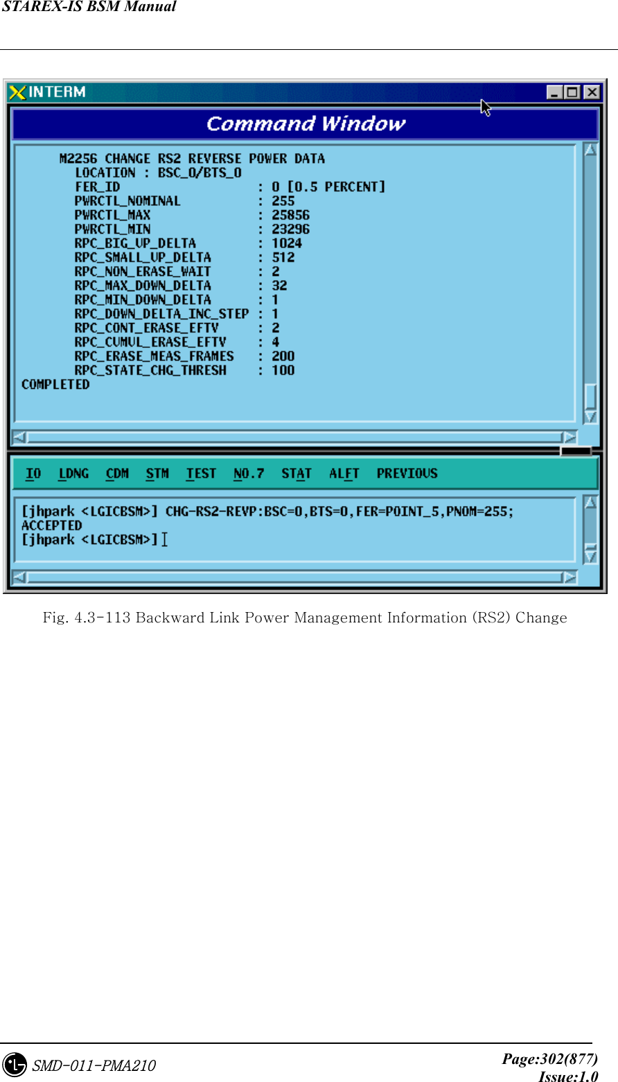
![STAREX-IS BSM Manual Page:301(877)Issue:1.0SMD-011-PMA210 Fig. 4.3-112 Forward Link Power Management Information (RS2) Change 4.3.5.13. Backward Link Power Management Information (RS2) Change To change Backward link power management information (RS2), click CDM->Change_Parameter_ Information_2_2-> CHG-RS2-REVP on the Command Window in order. Input the value to be changed in each field as shown below. • Command CHG-RS2-REVP :BSC=a ,BTS=b ,FER=c [,PNOM=d] [,PMAX=e] [,PMIN=f] [,RBUD=g] [,RSUD=h] [,RNEW=i] [,RMAXDD=j] [,RMINDD=k] [,RDDIS=l] [,RCONTEE=m] [,RCUMULEE=n] [,REMF=o] [,RSCT=p]; • Input CHG-RS2-REVP :BSC=0 ,BTS=0 ,FER=POINT_5,PNOM=255; • Output](https://usermanual.wiki/LG-Electronics-USA/3G1XINBTS.Users-Manual-Part-B/User-Guide-178302-Page-103.png)
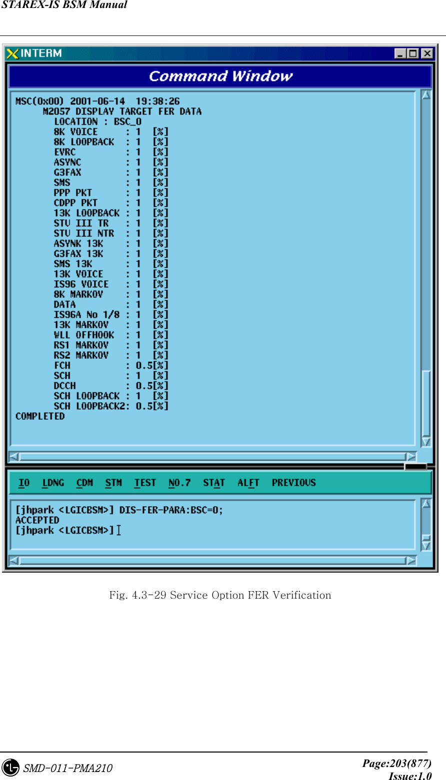
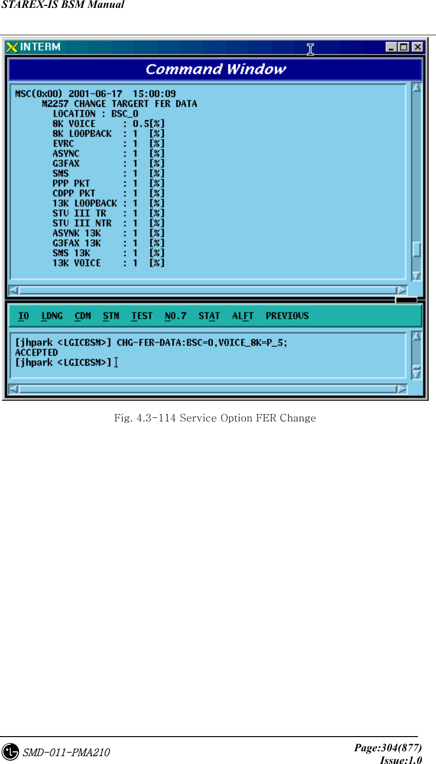
![STAREX-IS BSM Manual Page:303(877)Issue:1.0SMD-011-PMA210 4.3.5.14. Service Option FER Change To change Service Option FER, click CDM->Change_Parameter_ Information_2_2-> CHG-FER-PARA on the Command Window in order. Input the value to be changed in each field as shown below. • Command CHG-FER-DATA :BSC=a [,VOICE_8K=b] [,LOOPBK_8K=c] [,EVRC=d] [,ASYNC=e] [,G3FAX=f] [,SMS=g] [,PPP_PKT=h] [,CDPP_PKT=i] [,LOOPBK_13K=j] [,STU_TR=k] [,STU_NTR=l] [,ASYNC_13K=m] [,G3FAX_13K=n] [,SMS_13K=o] [,VOICE_13K=p] [,IS96_VOICE=q] [,MARKOV_8K=r] [,DATA=s] [,IS96A_1BY8=t] [,MARKOV_13K=u] [,WLL_OFFHOOK=v] [,RS1_MARKOV=w] [,RS2_MARKOV=x] [,FCH=y] [,SCH=z] [,DCCH=] [,SCH_LB=] [,SCH_LB2=]; • Input CHG-FER-DATA :BSC=0,VOICE_8K=P_5; • Output](https://usermanual.wiki/LG-Electronics-USA/3G1XINBTS.Users-Manual-Part-B/User-Guide-178302-Page-105.png)
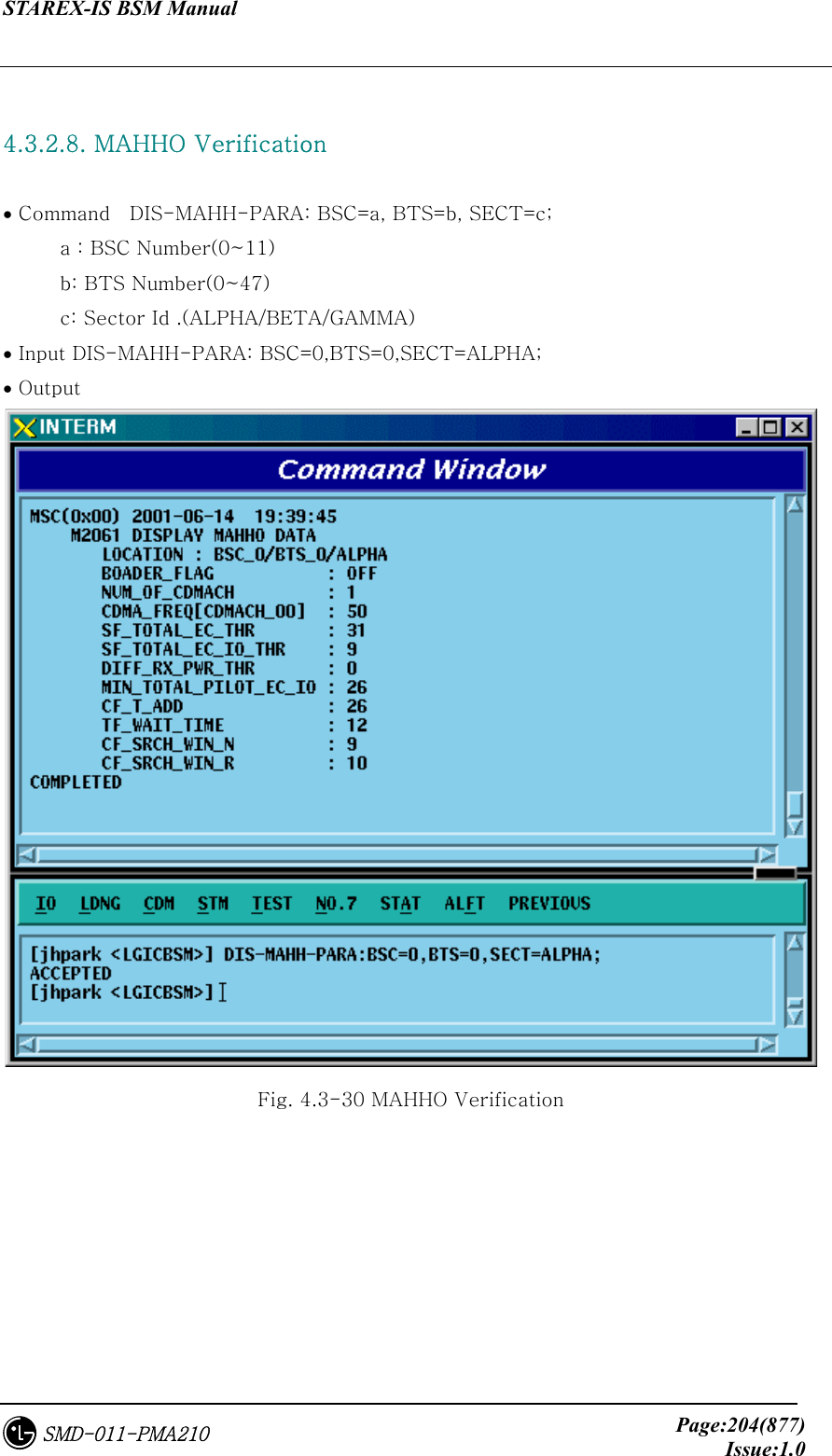
![STAREX-IS BSM Manual Page:305(877)Issue:1.0SMD-011-PMA210 4.3.5.15. MAHHO DATA Change To change MAHHO DATA, click the CDM->Change_Parameter_ Information_2-> CHG-MAHO-DATA on the Command Window in order. Input the value to be changed in each file as shown below. • Command CHG-MAHO-DATA :BSC=a ,BTS=b ,SECT=c [,BORDER_FLAG=d] [,BD_CLS=e] [,NUM_CHAN=f] [,CDMA_FREQ0=g] [,CDMA_FREQ1=h] [,CDMA_FREQ2=i] [,CDMA_FREQ3=j] [,CDMA_FREQ4=k] [,CDMA_FREQ5=l] [,CDMA_FREQ6=m] [,CDMA_FREQ7=n] [,CDMA_FREQ8=o] [,CDMA_FREQ9=p] [,CDMA_FREQ10=q] [,CDMA_FREQ11=r] [,STET=s] [,STEIT=t] [,DRPT=u] [,MIN_TOT=v] [,CF_T_ADD=w] [,TF_WAIT_TIME=x] [,SRCH_N=y] [,SRCH_R=z]; • Input CHG-MAHO-DATA :BSC=0 ,BTS=0 ,SECT=ALPHA,BORDER_FLAG=ON; • Output](https://usermanual.wiki/LG-Electronics-USA/3G1XINBTS.Users-Manual-Part-B/User-Guide-178302-Page-107.png)

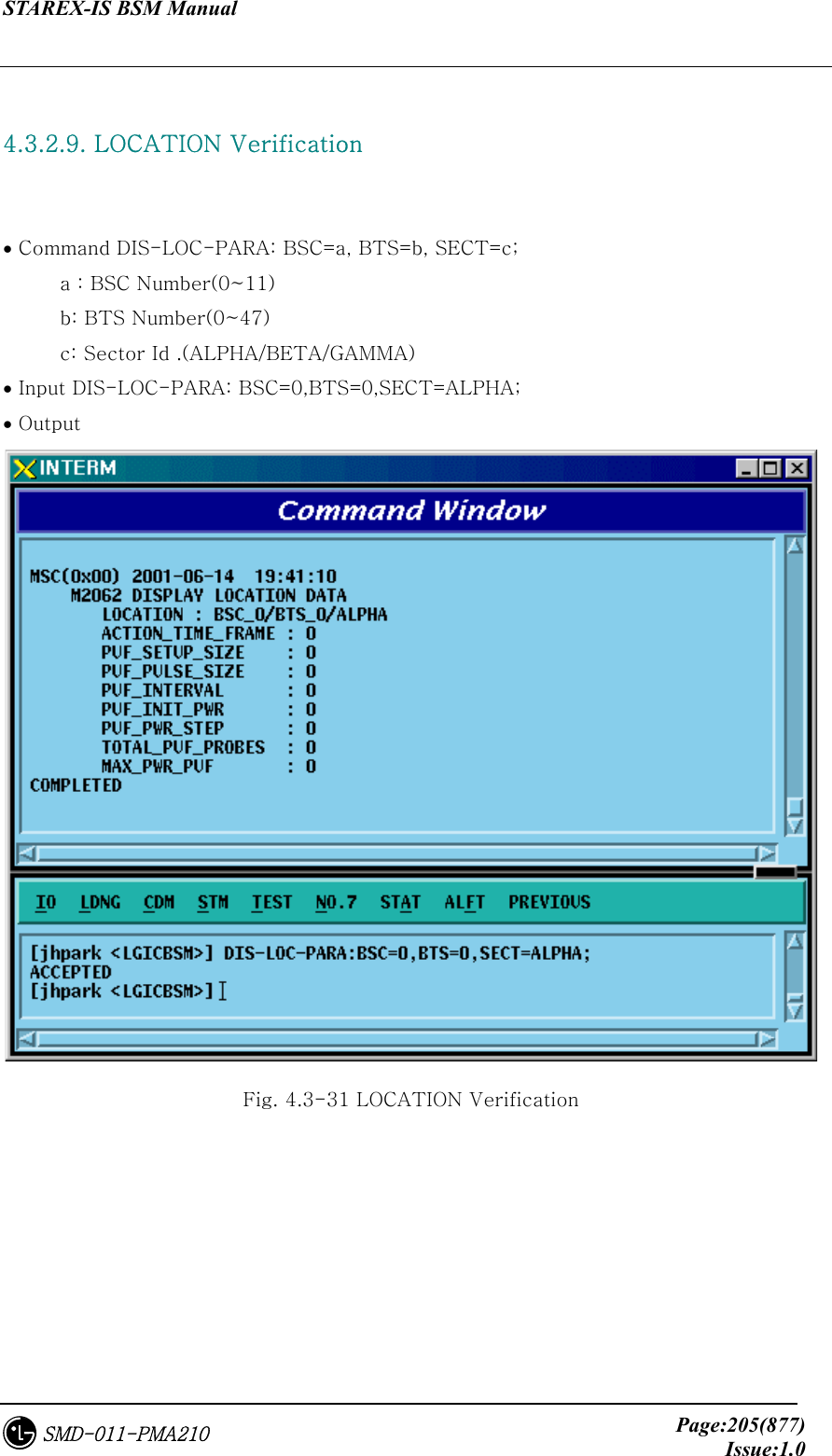
![STAREX-IS BSM Manual Page:307(877)Issue:1.0SMD-011-PMA210 4.3.5.16. LOCATION PARA Information Change To change LOCATION PARA information, click CDM->Change_Parameter_ Information_2-> CHG-LOC-PARA on the Command Window in order. Input the value to be changed in each field as shown below. • Command CHG-LOC-PARA :BSC=a ,BTS=b ,SECT=c [,ACT_T_FRM=d] [,PUF_ST_SZ=e][,PUF_P_SZ=f] [,PUF_INTERVAL=g] [,PUF_I_PWR=h] [,PUF_P_STEP=i] [,TOT_PUF_P=j] [,MAX_PWR_PUF=k]; • Input CHG-LOC-PARA :BSC=0 ,BTS=0 ,SECT=ALPHA,ACT_T_FRM=ON; • Output Fig. 4.3-116 LOCATION PARA Information Change](https://usermanual.wiki/LG-Electronics-USA/3G1XINBTS.Users-Manual-Part-B/User-Guide-178302-Page-109.png)
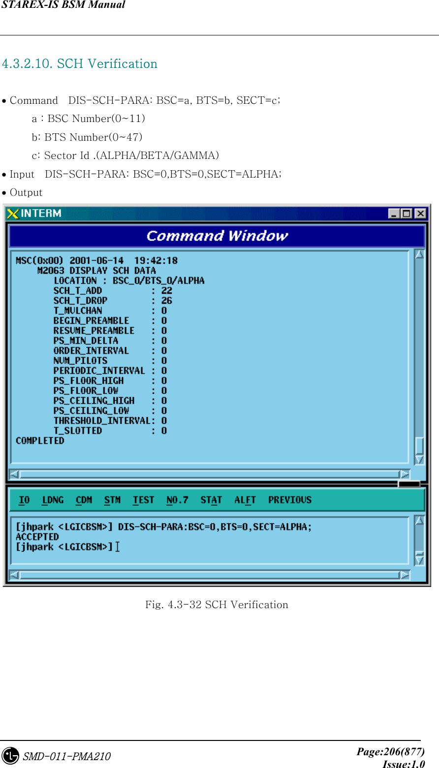
![STAREX-IS BSM Manual Page:308(877)Issue:1.0SMD-011-PMA210 4.3.5.17. SCH Parameter Information Change To change SCH PARA information, click CDM->Change_Parameter_ Information_2-> CHG-SCH-PARA on the Command Window in order. Input the value to be changed in each field as shown below. • Command CHG-SCH-PARA :BSC=a ,BTS=b ,SECT=c [,SCH_T_ADD=d] [,SCH_T_DROP=e] [,T_MULCHAN=f] [,BEGIN_PRMBL=g] [,RES_PRMBL=h] [,PS_MIN_DELTA=i] [,ORD_INTERVAL=j] [,NUM_PILOTS=k] [,PRD_INTERVAL=l] [,FLOOR_HIGH=m] [,FLOOR_LOW=n] [,PS_CEIL_HIGH=o] [,PS_CEIL_LOW=p] [,THSH_INTERVAL=q] [,T_SLOTTED=r]; • Input CHG-SCH-PARA :BSC=0 ,BTS=0 ,SECT=ALPHA,SCH_T_ADD=ON; • Output Fig. 4.3-117 SCH Parameter Information Change](https://usermanual.wiki/LG-Electronics-USA/3G1XINBTS.Users-Manual-Part-B/User-Guide-178302-Page-110.png)
![STAREX-IS BSM Manual Page:309(877)Issue:1.0SMD-011-PMA210 4.3.5.18. POWER CONTROL Parameter Information (1) Change To change POWER CONTROL Parameter information (1), click CDM->Change_Parameter_ Information_2-> CHG-PWR1-CTRL on the Command Window in order. Input the value to be changed in each field as shown below. • Command CHG-PWR1-CTRL :BSC=a ,BTS=b ,FER=c [,PWR_CNT_STEP=d] [,FPC_MODE=e] [,FPC_FC_INIT=f] [,FPC_FC_MIN=g] [,FPC_FCH_MAX=h] [,FPC_DCC_INIT=i] [,FPC_DCC_MIN=j] [,FPC_DCC_MAX=k] [,FPC_SC_INIT=l] [,FPC_SC_MIN=m] [,FPC_SC_MAX=n] [,FPC_THRESH=o] [,FCH_THSH_SC=p] [,FCH_ADJ_GAIN=q] [,DCC_ADJ_GAIN=r] [,SC0_ADJ_GAIN=s] [,SC1_ADJ_GAIN=t] [,FPC_SUBCH=u] [,RL_GAIN_ADJ=v] [,RL_TC_PICH=w] [,RL_SC_PILOT=x]; • Input CHG-PWR1-CTRL :BSC=0 ,BTS=0 ,FER=30,PWR_CNT_STEP=255; • Output](https://usermanual.wiki/LG-Electronics-USA/3G1XINBTS.Users-Manual-Part-B/User-Guide-178302-Page-111.png)
![STAREX-IS BSM Manual Page:311(877)Issue:1.0SMD-011-PMA210 4.3.5.19. POWER CONTROL Parameter Information (2) Change To change POWER CONTROL Parameter information (2), click CDM->Change_Parameter_ Information_2-> CHG-PWR2-CTRL on the Command Window in order. Input the value to be changed in each field as shown below. • Command CHG-PWR2-CTRL :BSC=a ,BTS=b ,FER=c ,USE_REV_P=d [,GAIN_1500=e] [,GAIN_2700=f] [,GAIN_4800=g] [,GAIN_9600=h] [,GAIN_1800=i] [,GAIN_3600=j] [,GAIN_7200=k] [,GAIN_14400=l] [,NORM_9600_5MS=m]; • Input CHG-PWR2-CTRL :BSC=0 ,BTS=0 ,FER=c ,USE_REV_P=USE_REV_P, GAIN_1500=255; • Output Fig. 4.3-119 POWER CONTROL Parameter Information (2) Change](https://usermanual.wiki/LG-Electronics-USA/3G1XINBTS.Users-Manual-Part-B/User-Guide-178302-Page-113.png)
![STAREX-IS BSM Manual Page:312(877)Issue:1.0SMD-011-PMA210 4.3.5.20. POWER CONTROL Parameter Information (3) Change To change POWER CONTROL Parameter information (3), click CDM->Change_Parameter_ Information_2-> CHG-PWR3-CTRL on the Command Window in order. Input the value to be changed in each field as shown below. • Command CHG-PWR3-CTRL :BSC=a ,BTS=b ,FER=c ,USE_REV_P=d ,USE_TUB_ENC=e [,GAIN_19200=f] [,GAIN_38400=g] [,GAIN_76800=h] [,GAIN_153600=i] [,GAIN_307200=j] [,GAIN_614400=k] [,GAIN_28800=l] [,GAIN_57600=m] [,GAIN_115200=n] [,GAIN_230400=o] [,GAIN_460800=p] [,GAIN_1036800=q]; • Input CHG-PWR3-CTRL :BSC=0 ,BTS=0 ,FER=0 ,USE_REV_P=NOUSE_REV_P , USE_TUB_ENC=NOUSE_TUB_ENC,GAIN_19200=255; • Output Fig. 4.3-120 POWER CONTROL Parameter Information (3) Change](https://usermanual.wiki/LG-Electronics-USA/3G1XINBTS.Users-Manual-Part-B/User-Guide-178302-Page-114.png)
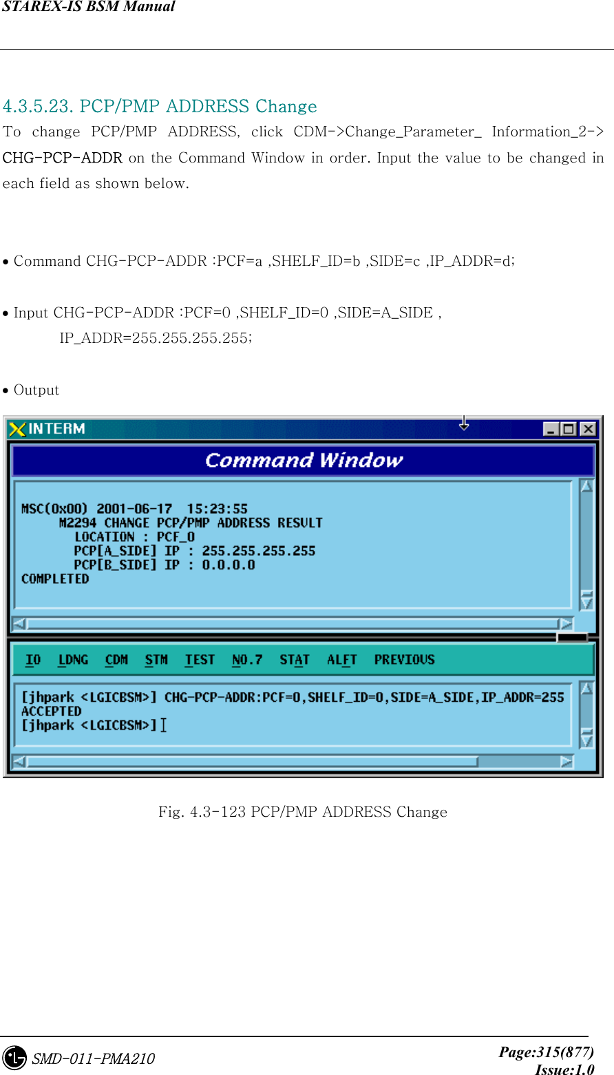
![STAREX-IS BSM Manual Page:314(877)Issue:1.0SMD-011-PMA210 4.3.5.22. PCF TIMER Change To change PCF TIMER, click CDM->Change_Parameter_ Information_2-> CHG-PCF-TIMER on the Command Window in order. Input the value to be changed in each field as shown below. • Command CHG-PCF-TIMER :PCP=a [,TRP_LIFETIME=b] [,TBSREQ9=c] [,TDISCON9=d] [,TWAITHO9=e] [,TREGREQ=f] [,RRQ_RETRY_CNT=g]; • Input CHG-PCF-TIMER :PCP=0,TRP_LIFETIME=255; • Output Fig. 4.3-122 PCF TIMER Change](https://usermanual.wiki/LG-Electronics-USA/3G1XINBTS.Users-Manual-Part-B/User-Guide-178302-Page-116.png)
![STAREX-IS BSM Manual Page:316(877)Issue:1.0SMD-011-PMA210 4.3.5.24. PIP ADDRESS Change To change PIP ADDRESS, click CDM->Change_Parameter_ Information_2-> CHG-PIP-ADDR on the Command Window in order. Input the value to be changed in each field as shown below. • Command CHG-PIP-ADDR :PCF=a ,SHELF_ID=b ,PIP_ID=c [,IP_ADDR=d] [,NETMASK=e] • Input CHG-PIP-ADDR :PCF=0 ,SHELF_ID=0 ,PIP_ID=0, NETMASK=255.255.0.0; • Output Fig. 4.3-124 PIP ADDRESS Change](https://usermanual.wiki/LG-Electronics-USA/3G1XINBTS.Users-Manual-Part-B/User-Guide-178302-Page-118.png)
![STAREX-IS BSM Manual Page:317(877)Issue:1.0SMD-011-PMA210 4.3.5.25. PCF PARAMETER Change To change PCF PARAMETER, click CDM->Change_Parameter_ Information_2-> CHG-PCF-PARA on the Command Window in order. Input the value to be changed in each field as shown below. • Command CHG-PCF-PARA :PCF=a [,AAA_TYPE=b] [,SID=c] [,NID=d] [,LTM_OFF=e] [,DAY_LT=f] [,PKZN_ID=g] [,ID_TYPE=h] [,GRE_SEQ=i] [,SEQ_TIMER=j] [,MSID_TYPE=k]; • Input CHG-PCF-PARA :PCF=0,AAA_TYPE=255,SEQ_TIMER=255; • Output Fig. 4.3-125 PCF PARAMETER Change](https://usermanual.wiki/LG-Electronics-USA/3G1XINBTS.Users-Manual-Part-B/User-Guide-178302-Page-119.png)
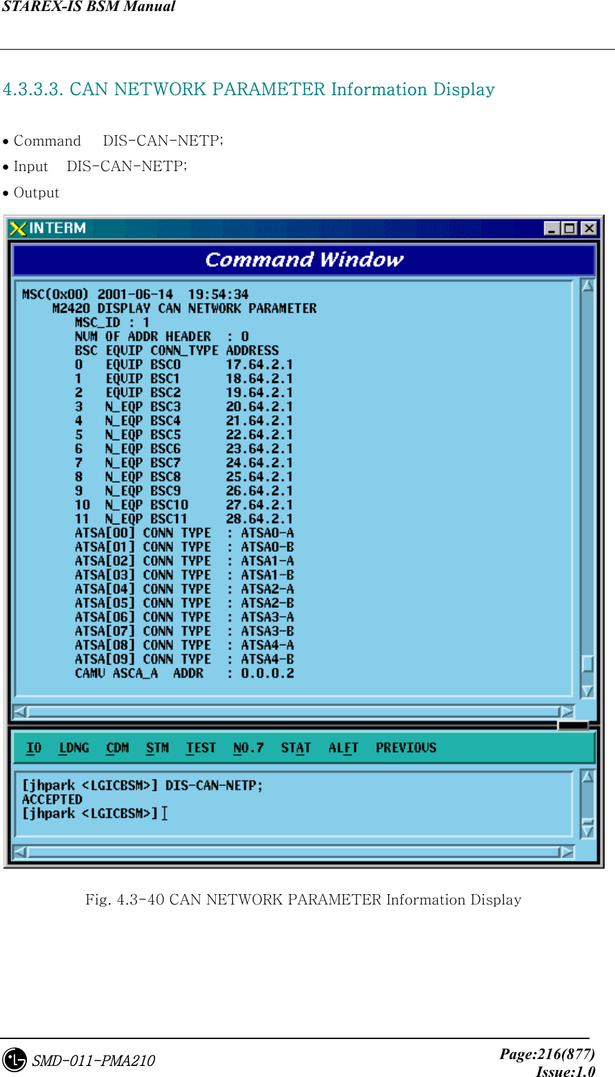
![STAREX-IS BSM Manual Page:318(877)Issue:1.0SMD-011-PMA210 4.3.6. Network Parameter Information Change (Change_Parameter_Info_3) 4.3.6.1. CAN INTER BSC AAL2 Setting Information Change • Command CHG-CAN-IUR: BSC=a, [BSC0_AAL2=b], [BSC1_AAL2=c], [BSC2_AAL2=d], [BSC3_AAL2=e], [BSC4_AAL2=f], [BSC5_AAL2=g], [BSC6_AAL2=h], [BSC7_AAL2=i], [BSC8_AAL2=j],[BSC9_AAL2=k],[BSC10_AAL2=l], [BSC11_AAL2=m], [NO_AAL2_VC=n]; • Input CHG-CAN-IUR: BSC=0, BSC0_AAL2=255 • Output](https://usermanual.wiki/LG-Electronics-USA/3G1XINBTS.Users-Manual-Part-B/User-Guide-178302-Page-120.png)
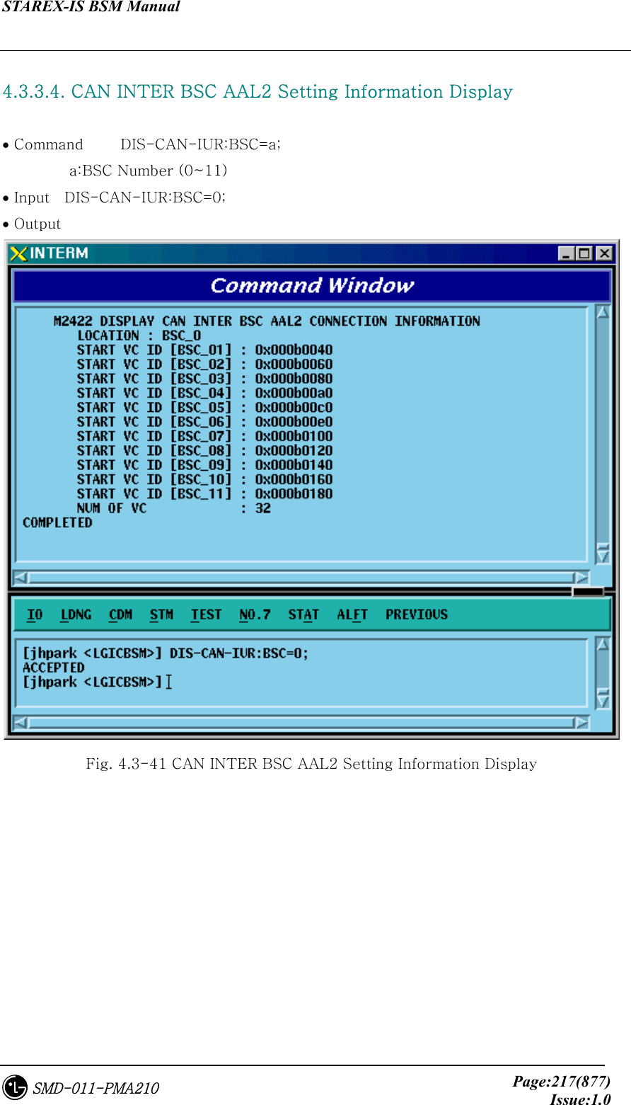
![STAREX-IS BSM Manual Page:319(877)Issue:1.0SMD-011-PMA210 4.3.6.2. CAN INTER BSC AAL5 Setting Information Change • Command CHG-CAN-BSC: [CAN0_START_AAL5=a], [CAN1_START_AAL5=b], [NO_AAL5_VC=0~], a ,b: 0~0xffffff c: 0~ • Input CHG-CAN-BSC: CAN0_START_AAL5=255 • Output](https://usermanual.wiki/LG-Electronics-USA/3G1XINBTS.Users-Manual-Part-B/User-Guide-178302-Page-121.png)
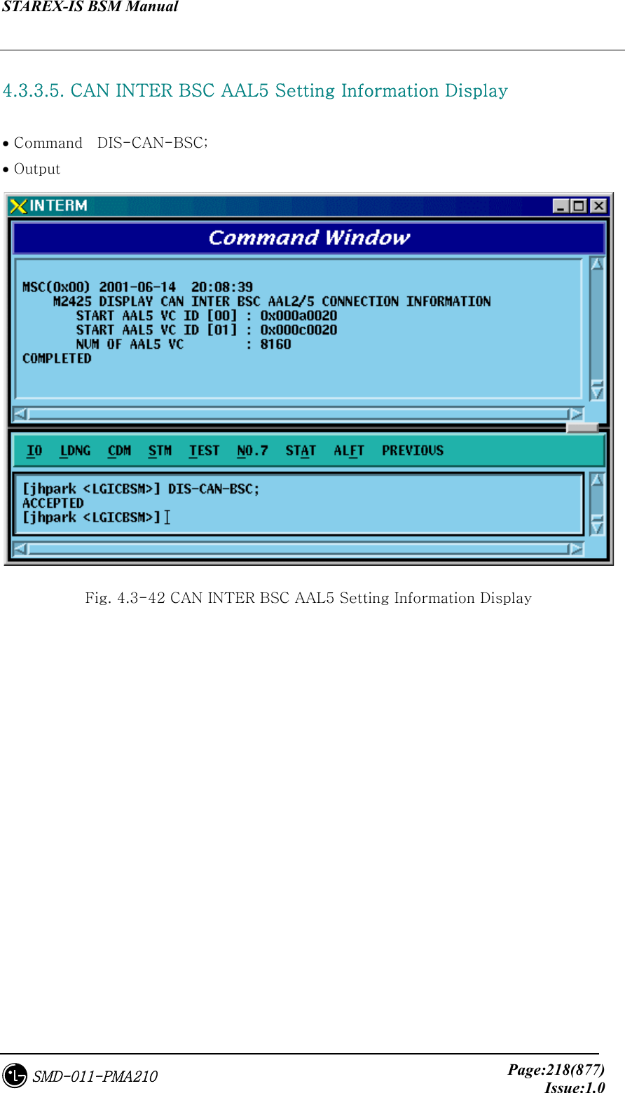
![STAREX-IS BSM Manual Page:320(877)Issue:1.0SMD-011-PMA210 4.3.6.3. CPN INTER DATA AAL5 Setting Information Change • Command CHG-CPN-DATA: [BSC0_AAL5=a], [BSC1_AAL5=b], [BSC2_AAL5=c], [BSC3_AAL5=d], [BSC4_AAL5=e], [BSC5_AAL5=f], [BSC6_AAL5=g], [BSC7_AAL5=h], [BSC8_AAL5=i], [BSC9_AAL5=j], [BSC10_AAL5=k], [BSC11_AAL5=l], [NO_AAL5_VC=m]; a ~n: BSC AAL5 (32~0xffffff) m: 0~32 • Input CHG-CPN-DATA: BSC0_AAL5=255; • Output](https://usermanual.wiki/LG-Electronics-USA/3G1XINBTS.Users-Manual-Part-B/User-Guide-178302-Page-122.png)
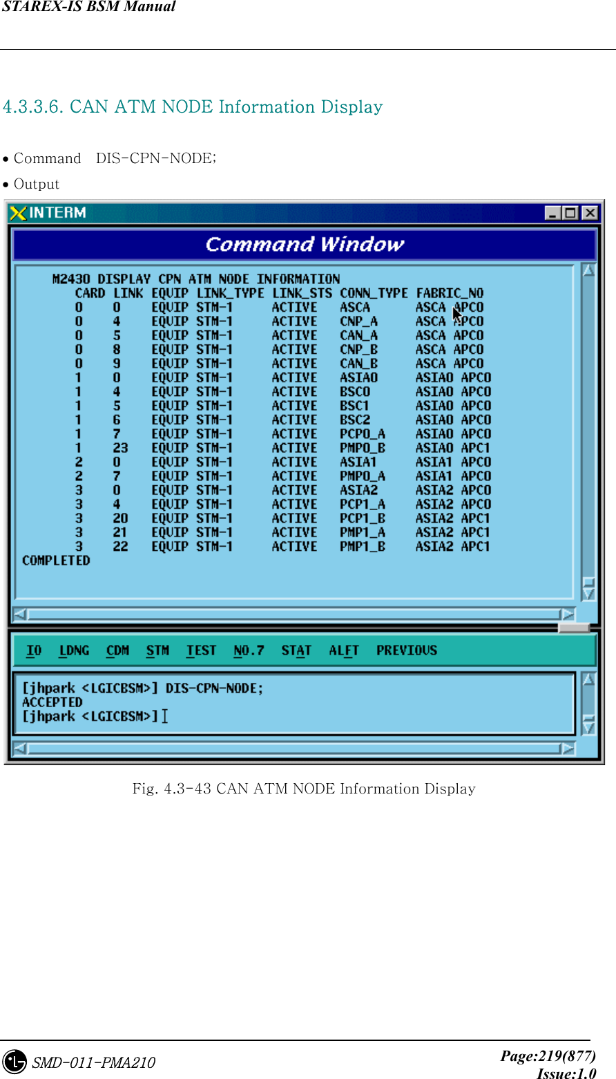
![STAREX-IS BSM Manual Page:321(877)Issue:1.0SMD-011-PMA210 4.3.6.4. CPN INTER PCF AAL5 Setting Information Change • Command CHG-CPN-PCF: [PIP0_0_AAL5=a], [PIP0_1_AAL5=b], [PIP1_0_AAL5=c], [PIP1_1_AAL5=d], [PIP2_0_AAL5=e], [PIP2_1_AAL5=f], [PIP3_0_AAL5=g], [PIP3_1_AAL5=h], [PIP4_0_AAL5=i], [PIP4_1_AAL5=j], [PIP5_0_AAL5=k], [PIP5_1_AAL5=l], [PIP6_0_AAL5=m], [PIP6_1_AAL5=n], [PIP7_0_AAL5=o], [PIP7_1_AAL5=p], [PIP8_0_AAL5=q], [PIP8_1_AAL5=r], [PIP9_0_AAL5=s], [PIP9_1_AAL5=t], [PIP10_0_AAL5=u], [PIP10_1_AAL5=v], [NO_AAL5_VC=w] a~v: PIP AAL5 (32~0xffffff) w: 0~480 • Input CHG-CPN-PCF: PIP0_0_AAL5=255 ; • Output](https://usermanual.wiki/LG-Electronics-USA/3G1XINBTS.Users-Manual-Part-B/User-Guide-178302-Page-123.png)
![STAREX-IS BSM Manual Page:322(877)Issue:1.0SMD-011-PMA210 4.3.6.5. BSC INTER BSC AAL2 Setting Information Change • Command CHG-BSC-IUR: BSC=a, [BSC0_AAL2=b], [BSC1_AAL2=c], [BSC2_AAL2=d], [BSC3_AAL2=e], [BSC4_AAL2=f], [BSC5_AAL2=g], [BSC6_AAL2=h], [BSC7_AAL2=i], [BSC8_AAL2=j], [BSC9_AAL2=k], [BSC10_AAL2=l], [BSC11_AAL2=m], [NO_AAL2_VC=n]; a : BSC Number(0~11) b~m: BSC AAL2 (0~0xffffff) n: 0~ • Input CHG-BSC-IUR: BSC=0, BSC0_AAL2=255; • Output](https://usermanual.wiki/LG-Electronics-USA/3G1XINBTS.Users-Manual-Part-B/User-Guide-178302-Page-124.png)
![STAREX-IS BSM Manual Page:323(877)Issue:1.0SMD-011-PMA210 4.3.6.6. BSC INTER BTSC AAL2 Setting Information Change • Command CHG-BSC-IUB: BSC=a, BTS=b, LICA=c, LINK=d, [LINK0_AAL2=e], [LINK1_AAL2=f], [LINK2_AAL2=g], [LINK3_AAL2=h], [LINK4_AAL2=i], [LINK5_AAL2=j], [LINK6_AAL2=k], [LINK7_AAL2=l], [LINK8_AAL2=m], [LINK9_AAL2=n], [LINK10_AAL2=o], [LINK11_AAL2=p], [LINK12_AAL2=q], [LINK13_AAL2=r], [LINK14_AAL2=s], [LINK15_AAL2=t] a : BSC Number(0~11) b : BTS Number(0~47) c : LICA Number(0~2) d : LINK Number(0~15) e~t: 0~0xffffff • Input CHG-BSC-IUB: BSC=0, BTS=0, LICA=0, LINK0_AAL2=255; • Output](https://usermanual.wiki/LG-Electronics-USA/3G1XINBTS.Users-Manual-Part-B/User-Guide-178302-Page-125.png)
![STAREX-IS BSM Manual Page:324(877)Issue:1.0SMD-011-PMA210 4.3.6.7. BSC INTER CAN AAL2/5 Setting Information Change • Command CHG-BSC-CAN: BSC=a, [CAN0_START_AAL5=b], [CAN1_START_AAL5=c], [NO_AAL5_VC=d] a: BSC Number(0~11) b,c: 32~0xffffff d: 0~8160 • Input CHG-BSC-CAN: BSC=0, CAN0_START_AAL5=255; • Output](https://usermanual.wiki/LG-Electronics-USA/3G1XINBTS.Users-Manual-Part-B/User-Guide-178302-Page-126.png)
![STAREX-IS BSM Manual Page:325(877)Issue:1.0SMD-011-PMA210 4.3.6.8. BSC INTER SLB AAL5 Setting Information • Command CHG-BSC-SLB: BSC=a, [SLP0_AAL5=b], [SLP1_AAL5=c], [SLP2_AAL5=d], [SLP3_AAL5=e], [SLP4_AAL5=f], [SLP5_AAL5=g], [SLP6_AAL5=h], [SLP7_AAL5=i], [SLP8_AAL5=j], [SLP9_AAL5=k], [SLP10_AAL5=l], [SLP11_AAL5=m], [SLP12_AAL5=n], [SLP13_AAL5=o], [SLP14_AAL5=p], [SLP15_AAL5=q], [SLP16_AAL5=r], [SLP17_AAL5=s], [NO_AAL5_VC=t] a: BSC Number(0~11) b~s: 40~0xffffff t: 0~984 • Input CHG-BSC-SLB: BSC=0, SLP0_AAL5=255; • Output](https://usermanual.wiki/LG-Electronics-USA/3G1XINBTS.Users-Manual-Part-B/User-Guide-178302-Page-127.png)
![STAREX-IS BSM Manual Page:326(877)Issue:1.0SMD-011-PMA210 4.3.6.9. BSC INTER VCB AAL5 Setting Information Change • Command CHG-BSC-VCB: BSC=a, [VCP0_AAL5=b], [VCP1_AAL5=c], [VCP2_AAL5=d], [VCP3_AAL5=e], [VCP4_AAL5=f], [VCP5_AAL5=g], [VCP6_AAL5=h], [VCP7_AAL5=i], [VCP8_AAL5=j], [VCP9_AAL5=k], [VCP10_AAL5=l], [VCP11_AAL5=m], [VCP12_AAL5=n], [VCP13_AAL5=o], [VCP14_AAL5=p], [VCP15_AAL5=q], [NO_AAL5_VC=r] a: BSC Number(0~11) b~q: 40~0xffffff r: 0~88 • Input CHG-BSC-VCB: BSC=0, VCP0_AAL5=255; • Output](https://usermanual.wiki/LG-Electronics-USA/3G1XINBTS.Users-Manual-Part-B/User-Guide-178302-Page-128.png)
![STAREX-IS BSM Manual Page:327(877)Issue:1.0SMD-011-PMA210 4.3.6.10. BSC INTER ALB AAL5 Setting Information Change • Command CHG-BSC-ALB: BSC=a, [ALMA0_ALP0_0=b], [ALMA0_ALP0_1=c], [ALMA0_ALP1_0=d], [ALMA0_ALP1_1=e], [ALMA0_ALP2_0=f], [ALMA0_ALP2_1=g], [ALMA0_ALP3_0=h], [ALMA0_ALP3_1=i], [ALMA0_ALP4_0=j], [ALMA0_ALP4_1=k], [ALMA1_ALP0_0=l], [ALMA1_ALP0_1=m], [ALMA1_ALP1_0=n], [ALMA1_ALP1_1=o], [ALMA1_ALP2_0=p], [ALMA1_ALP2_1=q], [ALMA1_ALP3_0=r], [ALMA1_ALP3_1=s], [ALMA1_ALP4_0=t], [ALMA1_ALP4_1=u], [NO_AAL5_VC=v] a: BSC Number(0~11) b~u: 32~0xffffff v: 0~2016 • Input CHG-BSC-ALB: BSC=0, ALMA0_ALP0_0=255; • Output](https://usermanual.wiki/LG-Electronics-USA/3G1XINBTS.Users-Manual-Part-B/User-Guide-178302-Page-129.png)
![STAREX-IS BSM Manual Page:328(877)Issue:1.0SMD-011-PMA210 4.3.6.11. BTS INTER RCU AAL5 Setting Information Change • Command CHG-BTS-RCU: BSC=a, BTS=b, RCU=c, [LICA0_AAL5=d], [LICA1_AAL5=e], [LICA2_AAL5=f], [LICA0_NO_VC=g], [LICA1_NO_VC=h], [LICA2_NO_VC=i] a: BSC Number(0~11) b:BTS Number(0~47) c: RCU Number(0~9) d~i: 0~ • Input CHG-BTS-RCU: BSC=0,BTS=0,RCU=0, LICA0_AAL5=255; • Output](https://usermanual.wiki/LG-Electronics-USA/3G1XINBTS.Users-Manual-Part-B/User-Guide-178302-Page-130.png)
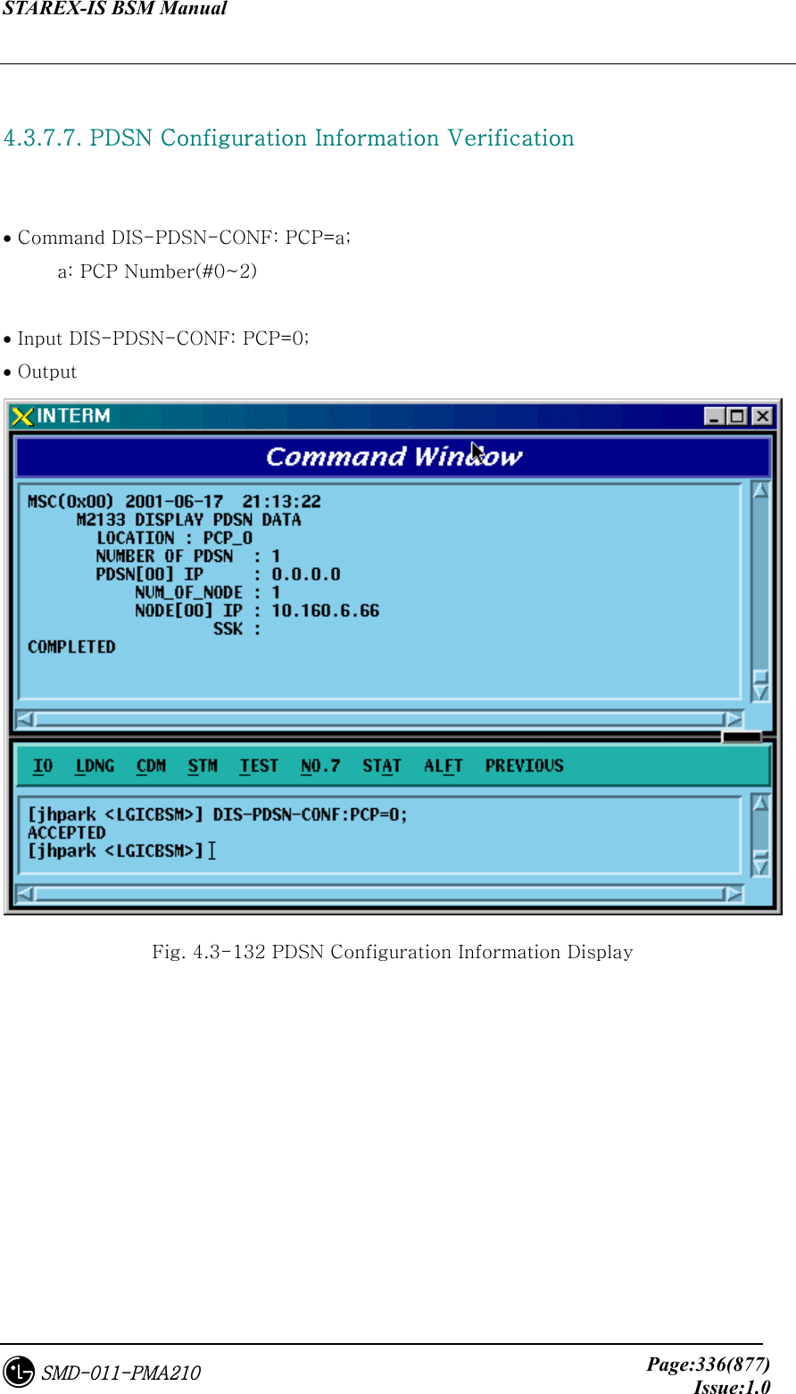
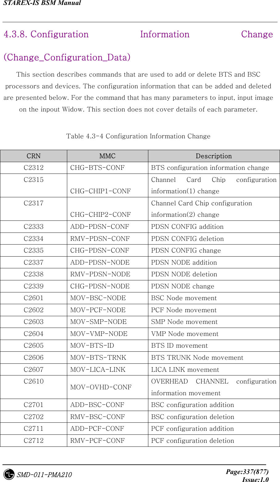
![STAREX-IS BSM Manual Page:339(877)Issue:1.0SMD-011-PMA210 4.3.8.1. BTS Configuration Information Change • Command CHG-BTS-CONF :BSC=a ,BTS=b [,PA_TYPE=c] [,ANT_TYPE=d] [,ANT_DUP=e] [,RX_DIV=f] [,LNA_EQP=g] [,RISA_EQP=h] [,BOTA_EQP=i]; • Input CHG-BTS-CONF: BSC=0, BTS=0,PA_TYPE=FA_NEQ; • Output Fig. 4.3-133 BTS Configuration Information Change Display](https://usermanual.wiki/LG-Electronics-USA/3G1XINBTS.Users-Manual-Part-B/User-Guide-178302-Page-141.png)
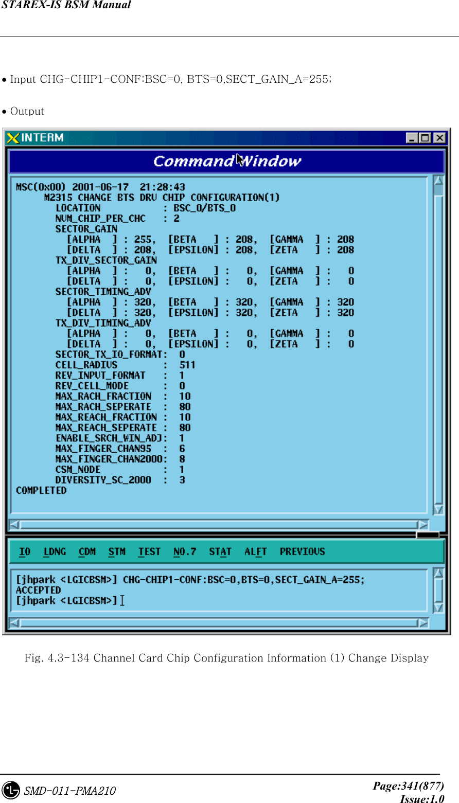
![STAREX-IS BSM Manual Page:340(877)Issue:1.0SMD-011-PMA210 4.3.8.2. Channel Card Chip Configuration Information (1) Change • Command CHG-CHIP1-CONF :BSC=a ,BTS=b [,SECT_GAIN_A=c] [,SECT_GAIN_B=d] [,SECT_GAIN_G=e] [,SECT_GAIN_D=f] [,SECT_GAIN_E=g] [,SECT_GAIN_Z=h] [,T_DIV_SECT_A=i] [,T_DIV_SECT_B=j] [,T_DIV_SECT_G=k] [,T_DIV_SECT_D=l] [,T_DIV_SECT_E=m] [,T_DIV_SECT_Z=n] [,SECT_T_ADV_A=o] [,SECT_T_ADV_B=p] [,SECT_T_ADV_G=q] [,SECT_T_ADV_D=r] [,SECT_T_ADV_E=s] [,SECT_T_ADV_Z=t] [,T_DIV_T_ADV_A=u] [,T_DIV_T_ADV_B=v] [,T_DIV_T_ADV_G=w] [,T_DIV_T_ADV_D=x] [,T_DIV_T_ADV_E=y] [,T_DIV_T_ADV_Z=z];](https://usermanual.wiki/LG-Electronics-USA/3G1XINBTS.Users-Manual-Part-B/User-Guide-178302-Page-142.png)
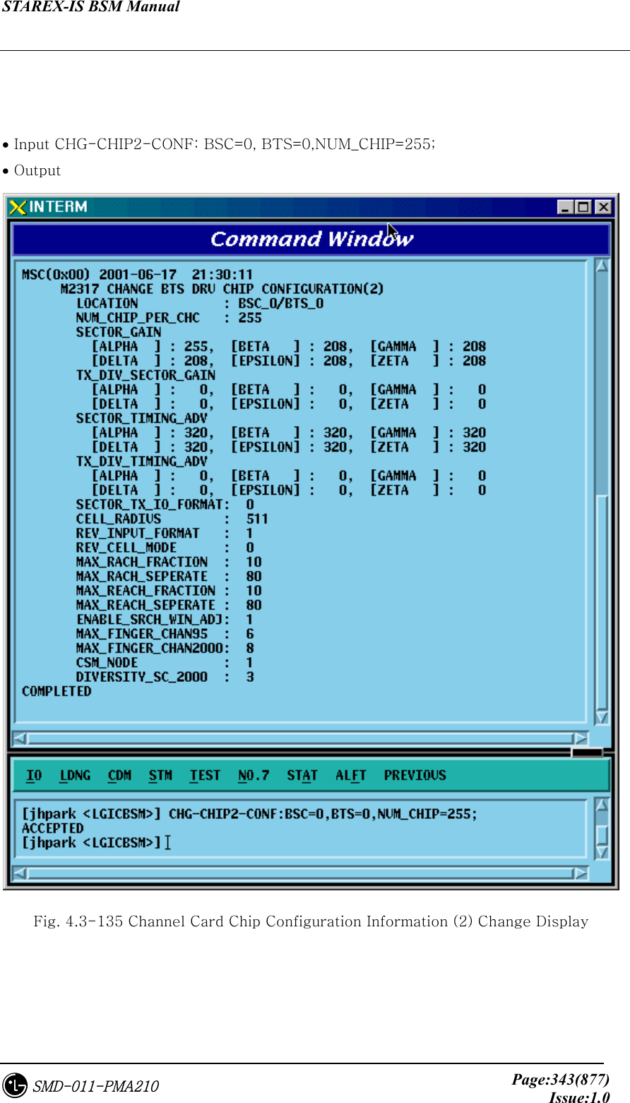
![STAREX-IS BSM Manual Page:342(877)Issue:1.0SMD-011-PMA210 4.3.8.3. Channel Card Chip Configuration Information (2) Change • Command CHG-CHIP2-CONF :BSC=a ,BTS=b [,NUM_CHIP=c] [,SECT_T_IO=d] [,CELL_RADIUS=e] [,REV_IN_FORM=f] [,R_CELL_MODE=g] [,MAX_RACH_F=h] [,MAX_RACH_S=i] [,MAX_REACH_F=j] [,MAX_REACH_S=k] [,SRCH_WIN_ADJ=l] [,MAX_CH95=m] [,MAX_CDMA2K=n] [,CSM_MODE=o] [,DIV_SCALE_2K=p];](https://usermanual.wiki/LG-Electronics-USA/3G1XINBTS.Users-Manual-Part-B/User-Guide-178302-Page-144.png)
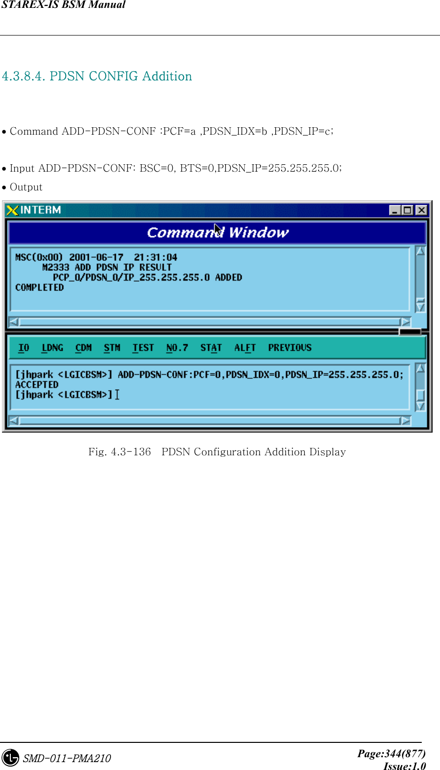
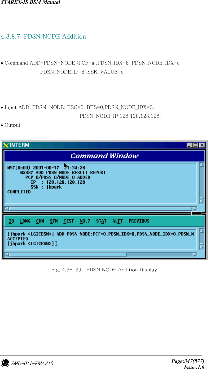
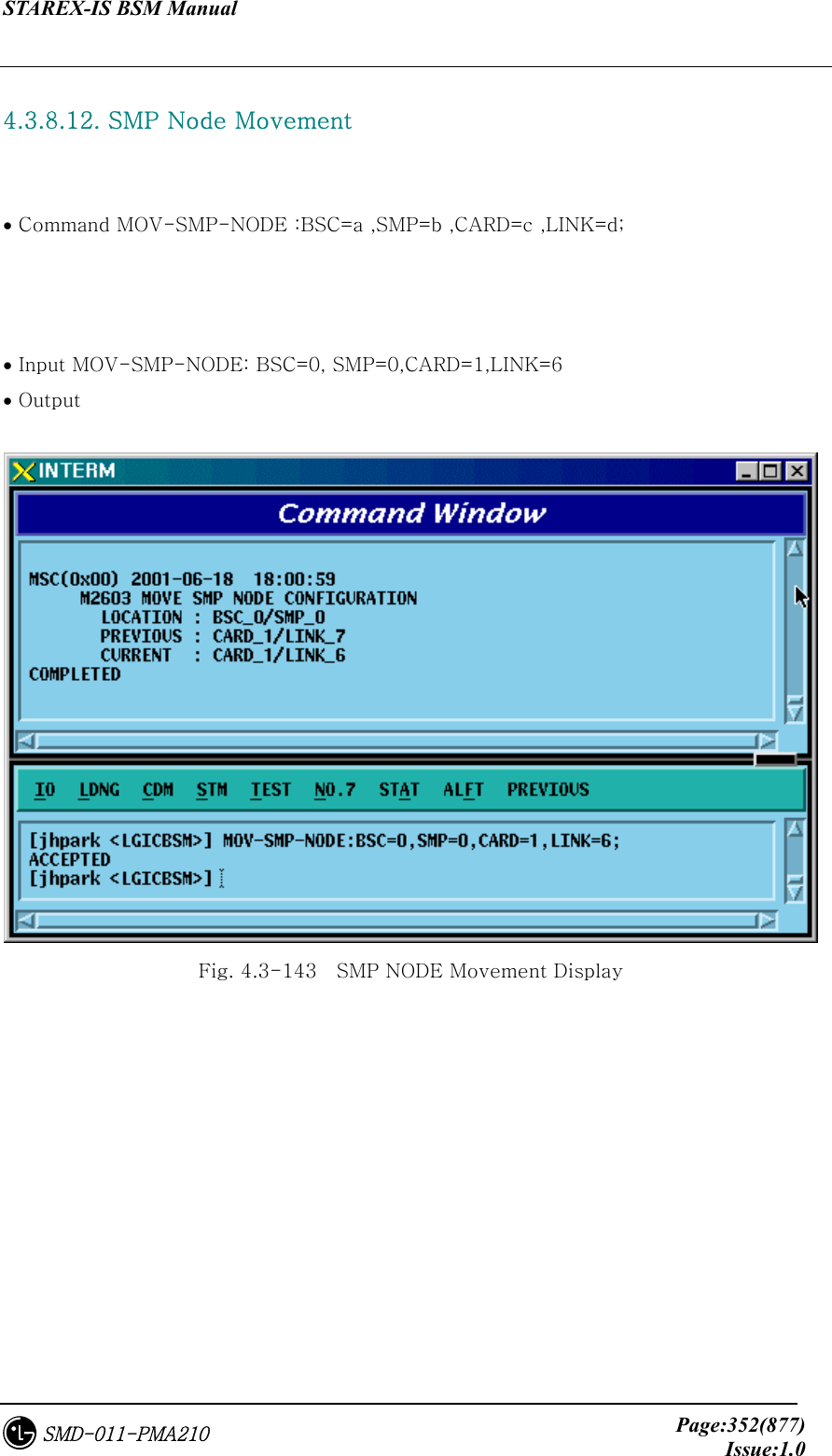
![STAREX-IS BSM Manual Page:349(877)Issue:1.0SMD-011-PMA210 4.3.8.9. PDSN NODE Change • Command CHG-PDSN-NODE :PCF=a ,PDSN_IDX=b ,PDSN_NODE_IDX=c [,PDSN_NODE_IP=d] [,SSK_VALUE=e] • Input CHG-PDSN-NODE: BSC=0, BTS=0,PDSN_IDX=0,PDSN_NODE_IDX=0, PDSN_NODE_IP=100.100.0.1, SSK_VALUE=gamdok; • Output Fig. 4.3-141 PDSN NODE Change Display](https://usermanual.wiki/LG-Electronics-USA/3G1XINBTS.Users-Manual-Part-B/User-Guide-178302-Page-151.png)
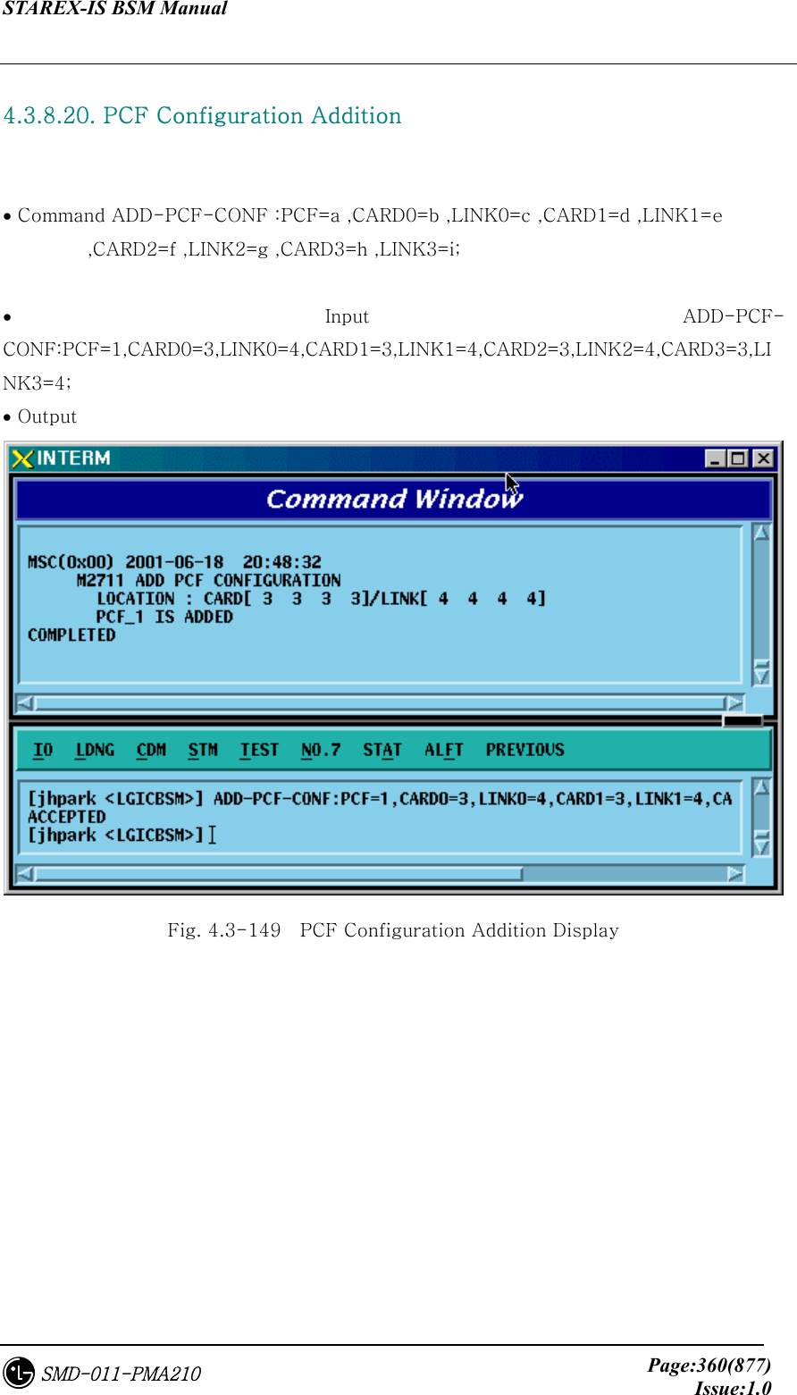
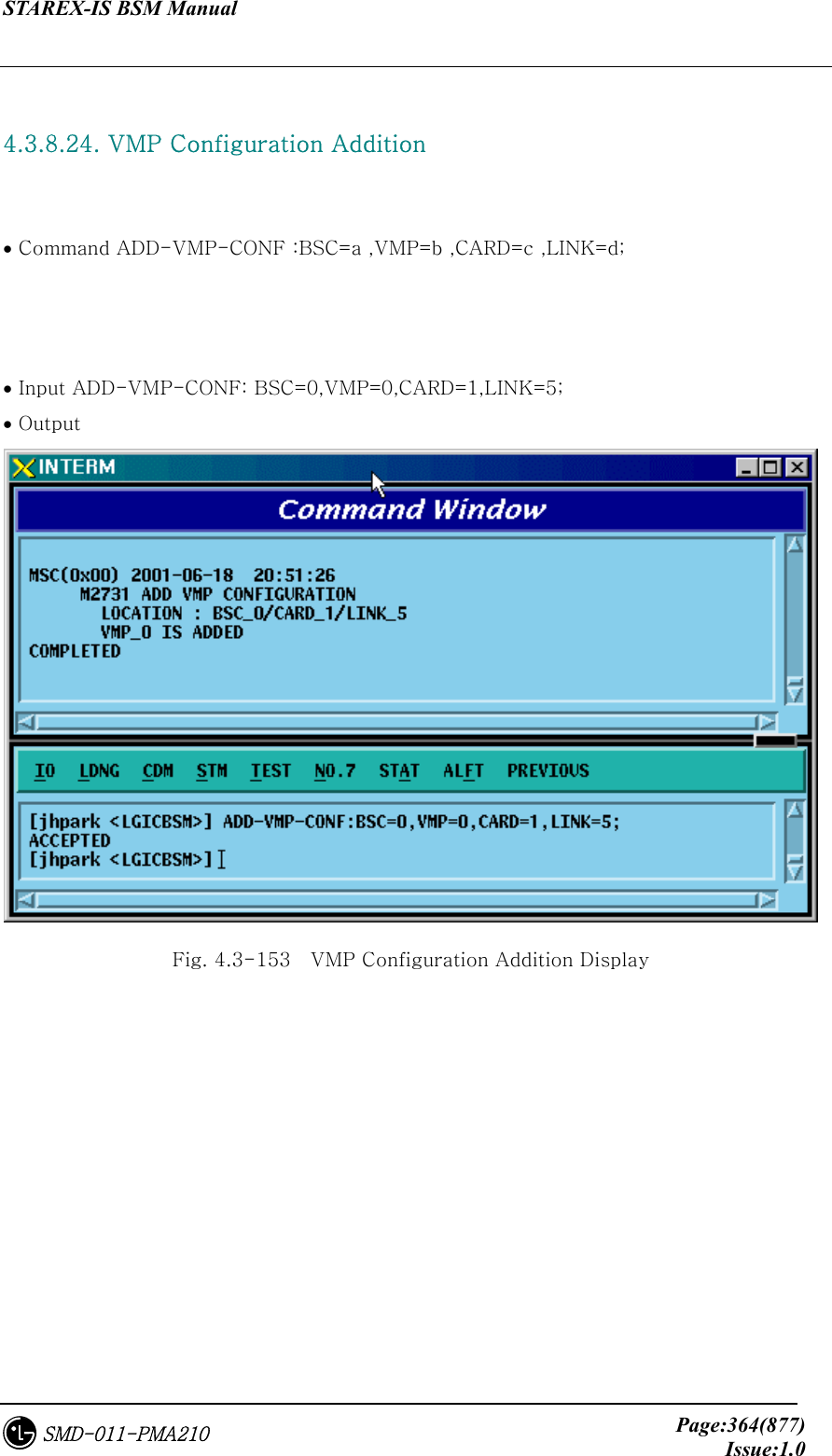
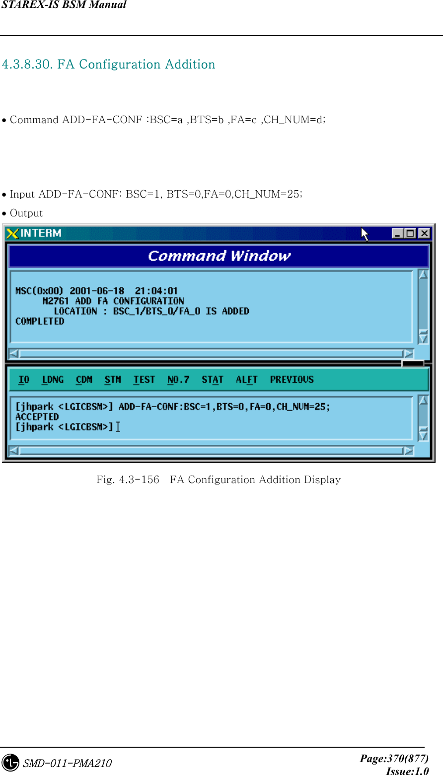
![STAREX-IS BSM Manual Page:366(877)Issue:1.0SMD-011-PMA210 4.3.8.26. BTS Configuration Addition • Command ADD-BTS-CONF :BSC=a ,BTS=b ,B_TYPE=c ,SECT_EQP=d ,SECT_RANGE=e ,ALMA=f ,ALPA=g ,ALPA_LINK=h ,LICA=i ,LICA_LINK=j ,FA0_CH_NUM=k ,PN_ALPHA=l [,PN_BETA=m] [,PN_GAMMA=n] [,PN_DELTA=o] [,PN_EPSILON=p] [,PN_ZETA=q] [,PA_TYPE=r] [,ANT_TYPE=s] [,LNA_TYPE=t] [,RISA_EQP=u] [,BOTA_EQP=v]; • Input Input ADD-BTS-CONF: BSC=0, BTS=0; -> ADD-BTS-CONF: BSC=1, BTS=0,B_TYPE=STANDARD,SECT_EQP=OMNI; • Output](https://usermanual.wiki/LG-Electronics-USA/3G1XINBTS.Users-Manual-Part-B/User-Guide-178302-Page-168.png)

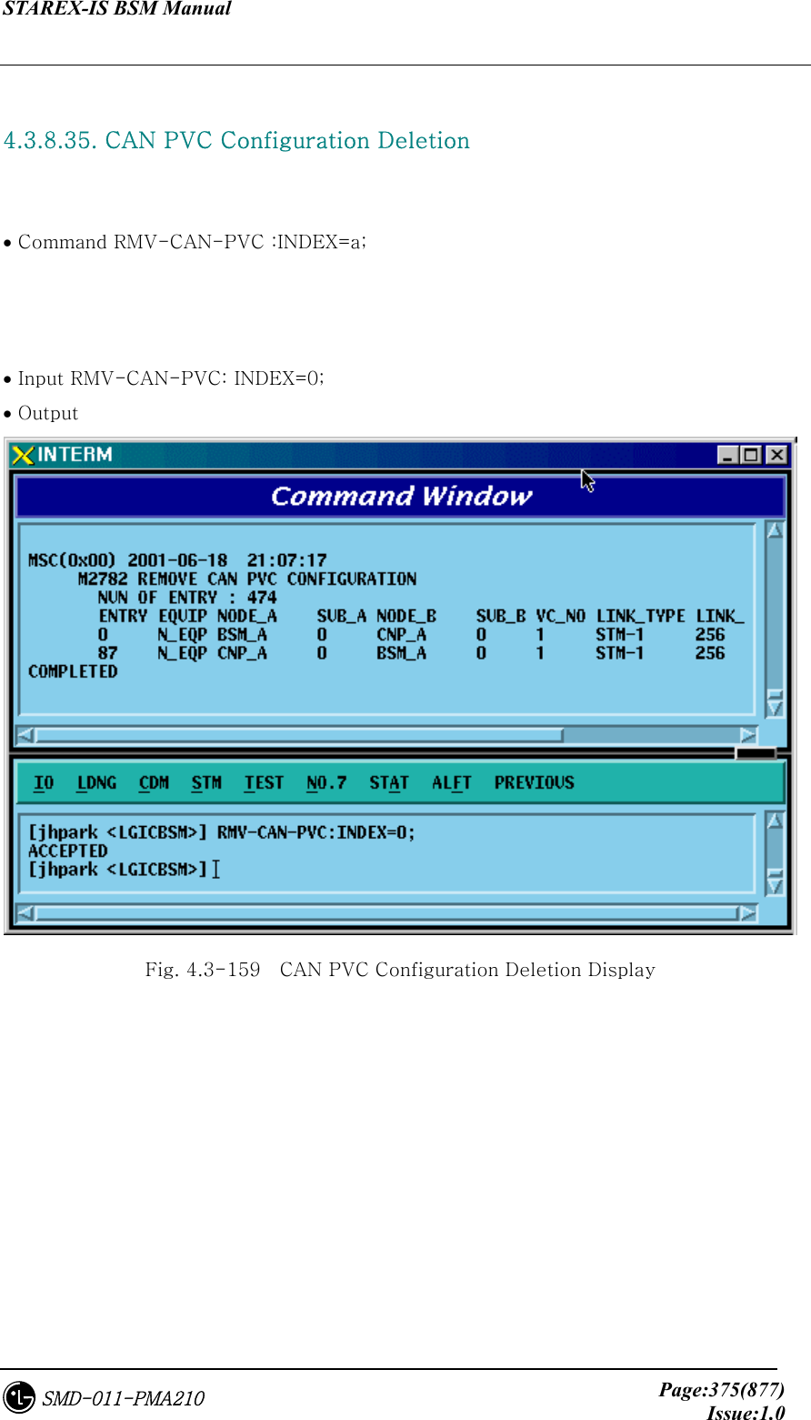
![STAREX-IS BSM Manual Page:374(877)Issue:1.0SMD-011-PMA210 4.3.8.34. CAN PVC Configuration Addition • Command ADD-CAN-PVC :NODE_A=a ,NODE_B=b ,VPCI_A=c ,VPCI_B=d [,NO_VC=e] ; • Input ADD-CAN-PVC: NODE_A=CTYPE_BSM_A, NODE_B=CTYPE_CNP_A, VPCL_A=0,VPCL_B=0; • Output Fig. 4.3-158 CAN PVC Configuration Addition Display](https://usermanual.wiki/LG-Electronics-USA/3G1XINBTS.Users-Manual-Part-B/User-Guide-178302-Page-176.png)
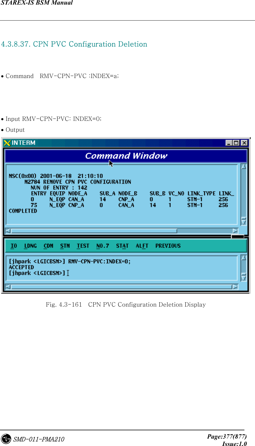
![STAREX-IS BSM Manual Page:376(877)Issue:1.0SMD-011-PMA210 4.3.8.36. CPN PVC Configuration Addition • Command ADD-CPN-PVC :NODE_A=a ,NODE_B=b ,VPCI_A=c ,VPCI_B=d [,NO_VC=e] ; • Input ADD-CPN-PVC:NODE_A=CTYPE_CAN_A, NODE_B=CTYPE_CAN_B, VPCI_A=0, VPCI_B=0; • Output Fig. 4.3-160 CPN PVC Configuration Addition Display](https://usermanual.wiki/LG-Electronics-USA/3G1XINBTS.Users-Manual-Part-B/User-Guide-178302-Page-178.png)
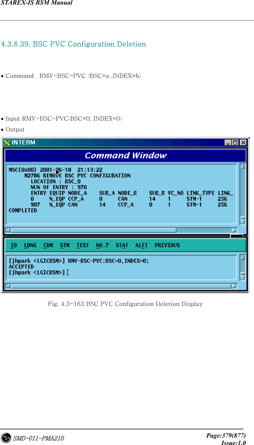
![STAREX-IS BSM Manual Page:378(877)Issue:1.0SMD-011-PMA210 4.3.8.38. BSC PVC Configuration Addition • Command ADD-BSC-PVC :BSC=a ,NODE_A=b ,NODE_B=c ,VPCI_A=d ,VPCI_B=e [,NO_VC=f]; • Input ADD-BSC-PVC:BSC=0, NODE_A=CTYPE_CCP_A, NODE_B=CTYPE_CCP_B, VPCI_A=0, VPCI_B=0; • Output Fig. 4.3-162 BSC PVC Configuration Addition Display](https://usermanual.wiki/LG-Electronics-USA/3G1XINBTS.Users-Manual-Part-B/User-Guide-178302-Page-180.png)
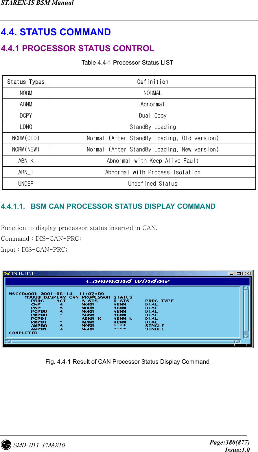
![STAREX-IS BSM Manual Page:381(877)Issue:1.0SMD-011-PMA210 4.4.1.2. BSC Processor Status Display Command Function to display Processor status inserted in BSC. Command : DIS-BSC-PRC[:BSC=a]; a : BSC Number(0~11) Input : DIS-BSC-PRC:BSC=0; Fig. 4.4-2 Result of BSC Processor Status Display 4.4.1.3. Status Display Command of BTS Processor Function to display operation status of processors mounted in all the BTSs within the corresponding BSC or in each BTS Command : DIS-BTS-STS:BSC=a[,BTS=b]; a:BSC Number (0~11) b:BTS Number (0~47) Input : DIS-BTS-STS:BSC=0,BTS=0; Output Fig. 4.4-3 Result of BTS Processor Status Display Command](https://usermanual.wiki/LG-Electronics-USA/3G1XINBTS.Users-Manual-Part-B/User-Guide-178302-Page-183.png)
![STAREX-IS BSM Manual Page:382(877)Issue:1.0SMD-011-PMA210 4.4.1.4. Processor Restart Command Function to restart Processors • Command : RST-PRC[:BSC=a][,BTS=b],RANGE=c,SIDE=d,CLS=e; a : BSC Number (0~11) b : BTS Number (0~47) c : Scope of restart(All the Processors of CCP, PNP,NCP,PCP., etc.) d : Side to restart (A,B,BOTH) e : Class (RESTART, REBOOT, FLASH) RESTART : Restart O/S and receive loading of PLD only. REBOOT : It executes BOOTER. In case of the processors equipped with Flash ROM, they check upper level processors and version of each block. If they are different, they receive loading from the upper level processors. However, if they are the same, they do not receive loading from the upper level processors. The processors with no Flash ROM receive loading from the upper level processors without checking version. . For reference, Active Side before and after reboot does not change. FLASH : Delete Flash content of the Processor with Flash ROM equipped and reboot it to receive loading of all the files from the upper level Processor. For reference, Active Side before and after Flash Reboot changes. Input : RST-PRC:BSC=0,BTS=0,RANGE=RCP00,SIDE=A,CLS=RESTART; Fig. 4.4-4 Result of Processor Restart Command](https://usermanual.wiki/LG-Electronics-USA/3G1XINBTS.Users-Manual-Part-B/User-Guide-178302-Page-184.png)
![STAREX-IS BSM Manual Page:383(877)Issue:1.0SMD-011-PMA210 4.4.1.5. CAN Processor H/W RESET(ISOLATION) COMMAND Function to reset CAN Processor H/W. Command : RMT-CAN-PRC:PROC=a,SIDE=b,CLS=c; a: Processor Name : CNP,PNP,PCP,PMP b: Side : A,B c: CLASS : HARDRST,ISOLAT,UNISOL HARDRST : Function to reset Processor on H/W Level (using Register Setting). ISOLAT : Function to isolate Processor on H/W Level (maintaining Status of RESET) UNISOL : Function to release the isolation Input : RMT-CAN-PRC:PROC=PNP,SIDE=A,CLS=ISOLAT; Fig. 4.4-5 CAN Processor H/W Command Result 4.4.1.6. BSC Processor H/W RESET(ISOLATION) COMMAND Function to reset BSC Processor H/W. Command : RMT-BSC-PRC:BSC=a,PROC=b,[SIDE=c],CLS=d; a: BSC Number b: Processor Name : CCP,NCP,SCP,ALP,SMP,VMP c: Side : A,B d: CLASS : HARDRST,ISOLAT,UNISOL HARDRST : Function to RESET Processor on H/W Level (using Register Setting). ISOLAT : Function to isolate Processor on H/W Level (RESET Status maintained) UNISOL : Function to release isolation](https://usermanual.wiki/LG-Electronics-USA/3G1XINBTS.Users-Manual-Part-B/User-Guide-178302-Page-185.png)
![STAREX-IS BSM Manual Page:384(877)Issue:1.0SMD-011-PMA210 Input : RMT-BSC-PRC:BSC=0,PROC=NCP,SIDE=A,CLS=ISOLAT; Fig. 4.4-6 BSC Processor H/W Command Result 4.4.1.7. BTS Processor H/W RESET(ISOLATION) COMMAND Function to BSC Processor H/W. Command : RMT-BTS-PRC:BSC=a,BTS=b,PROC=c,[SIDE=d],CLS=e; a: BSC Number b: BTS Number c: Processor Name : BSP,BPP,CRP,RCP(00~05) d: Side : A,B e: CLASS : HARDRST,ISOLAT,UNISOL HARDRST : Function to RESET Processor on H/W Level (using Register Setting). ISOLAT : Function to isolate Processor on H/W Level (RESET Status maintained) UNISOL : Function to release isolation Input : RMT-BTS-PRC:BSC=0,BTS=0,PROC=BSP,SIDE=A,CLS=ISOLAT; Fig. 4.4-7 BTS Processor H/W RESET(ISOLATION) Command Display Result](https://usermanual.wiki/LG-Electronics-USA/3G1XINBTS.Users-Manual-Part-B/User-Guide-178302-Page-186.png)
![STAREX-IS BSM Manual Page:385(877)Issue:1.0SMD-011-PMA210 4.4.1.8. Processor Switch Over(Switch) Command Function to Switch over Processor. Switching Over Command is executed for duplicated Processors and is performed only when both sides of Processors are in a normal status. Command : SWT-PRC [:BSC=a] [,BTS=b] ,PROC=c; a: BSC Number b: BTS Number c: Processor Name : CNP, PNP, PCP00, PCP01,PCP02, PMP00, PMP01,PMP02, CCP, NCP, SCP,ALP, BSP, CRP, RCP00, RCP01, RCP02, RCP03,RCP04, RCP05 Input : SWT-PRC :BSC=1 ,PROC=CCP; Fig. 4.4-8 Processor Switch Over(Switch) Command Display Result 4.4.2. Network Status Control Table 4.4-2 Network Node Status LIST Status Types Definition Description NORM Normal Normal Operation NOR_A Normal Act While normally operated, Act Status is maintained (Duplicated node) NOR_S Normal Standby While normally operated, Standby Status is maintained (Duplicated node)](https://usermanual.wiki/LG-Electronics-USA/3G1XINBTS.Users-Manual-Part-B/User-Guide-178302-Page-187.png)
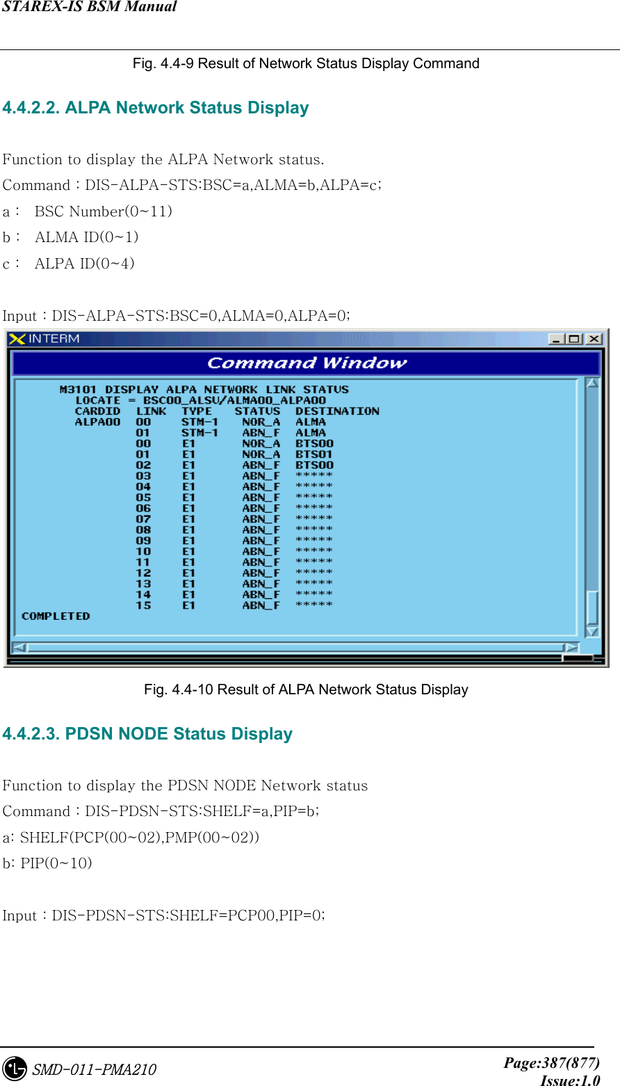
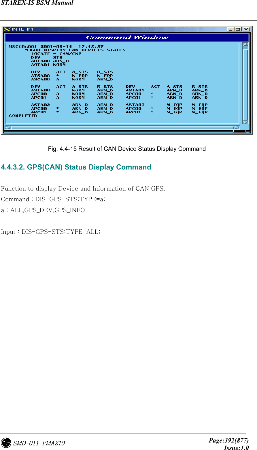
![STAREX-IS BSM Manual Page:386(877)Issue:1.0SMD-011-PMA210 ABN_D Abnormal Deletion card is removed ABN_F Abnormal Fault Local Fault occurred ABN_M Abnormal MMC Block Blocked Status by User’s MMC INIT Initial Even equipped to PLD, a processor managing the corresponding device does not normally operate until now AB_OB Abnormal Online Block Based on judgment that a normal call is impossible due to faults in other devices, the corresponding device is blocked N_EQP Not Equipped Card Type is not defined in PLD 4.4.2.1. Network Status Display Command Function to display the BSS Network status. Command : DIS-NET-STS: [BSC=a],[BTS=b],SHELF=c,CARD=d,ID=e,[CHIP=f]; a : BSC Number b : BTS Number c : SHELF NAME(CAMU,CAMDU,ASMU,ALSU,BANU) d : CARD NAME(ASCA,ASIA,AOTA,ATSA,ALMA,LICA) e : CARD ID(0~3) f : CHIP Number(0~1) Input : DIS-NET-STS:BSC=0,BTS=0,SHELF=BANU,CARD=LICA,ID=0;](https://usermanual.wiki/LG-Electronics-USA/3G1XINBTS.Users-Manual-Part-B/User-Guide-178302-Page-188.png)
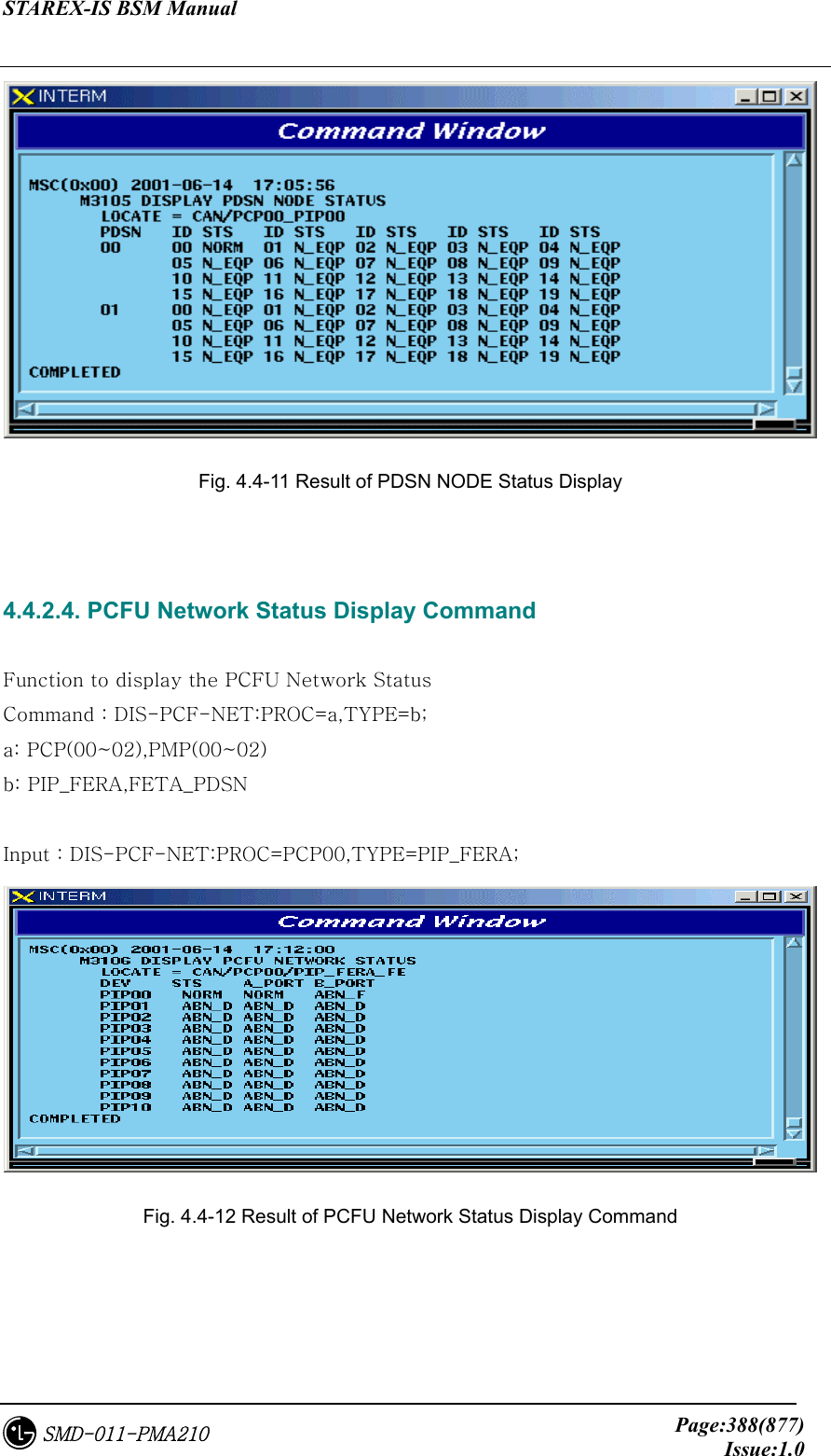
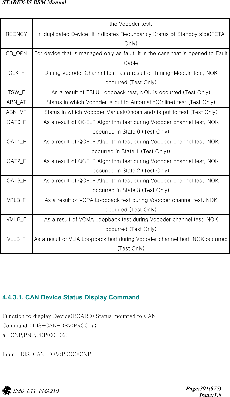
![STAREX-IS BSM Manual Page:389(877)Issue:1.0SMD-011-PMA210 4.4.2.5. ALPA Network Block Command Function to block the ALPA Network. Command : BLK-ALPA:BSC=a,ALMA=b,ALPA=c,[TYPE=d],[LINK=e]; a: BSC Number(00~11) b: ALMA ID(0~1) c: ALPA ID(0~4) d: TYPE(STM_1,E1) e: LINK(0~15) Input : BLK-ALPA:BSC=0,ALMA=0,ALPA=0,TYPE=STM_1,LINK=0; Fig. 4.4-13 Result of ALPA Network Block Command 4.4.2.6. UNBlock Command Function to unblock the ALPA Network. Command : UBLK-ALPA:BSC=a,ALMA=b,ALPA=c,[TYPE=d],[LINK=e]; a: BSC Number(00~11) b: ALMA ID(0~1) c: ALPA ID(0~4) d: TYPE(STM_1,E1) e: LINK(0~15) Input : UBLK-ALPA:BSC=0,ALMA=0,ALPA=0,TYPE=STM_1,LINK=0;](https://usermanual.wiki/LG-Electronics-USA/3G1XINBTS.Users-Manual-Part-B/User-Guide-178302-Page-191.png)
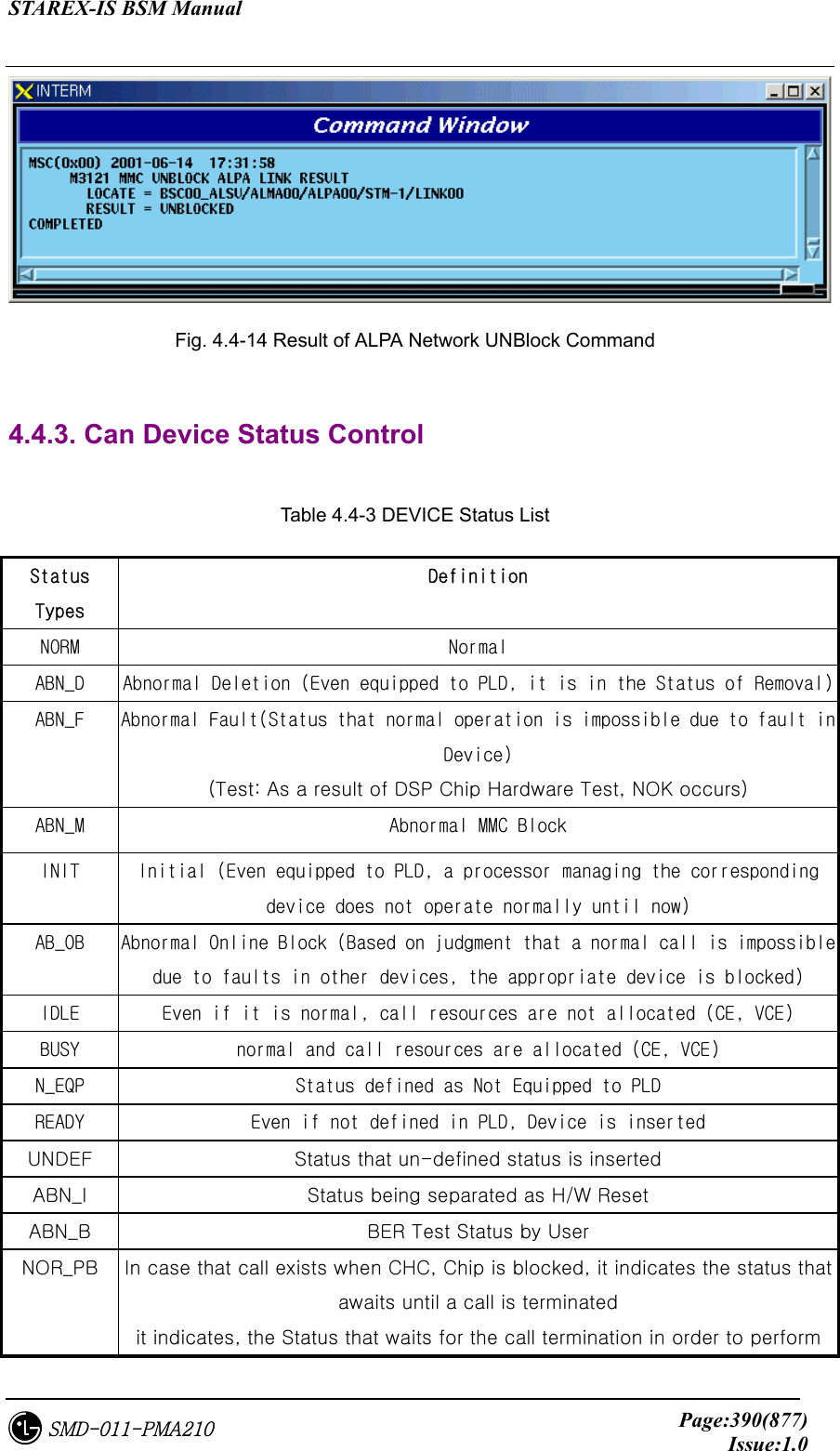
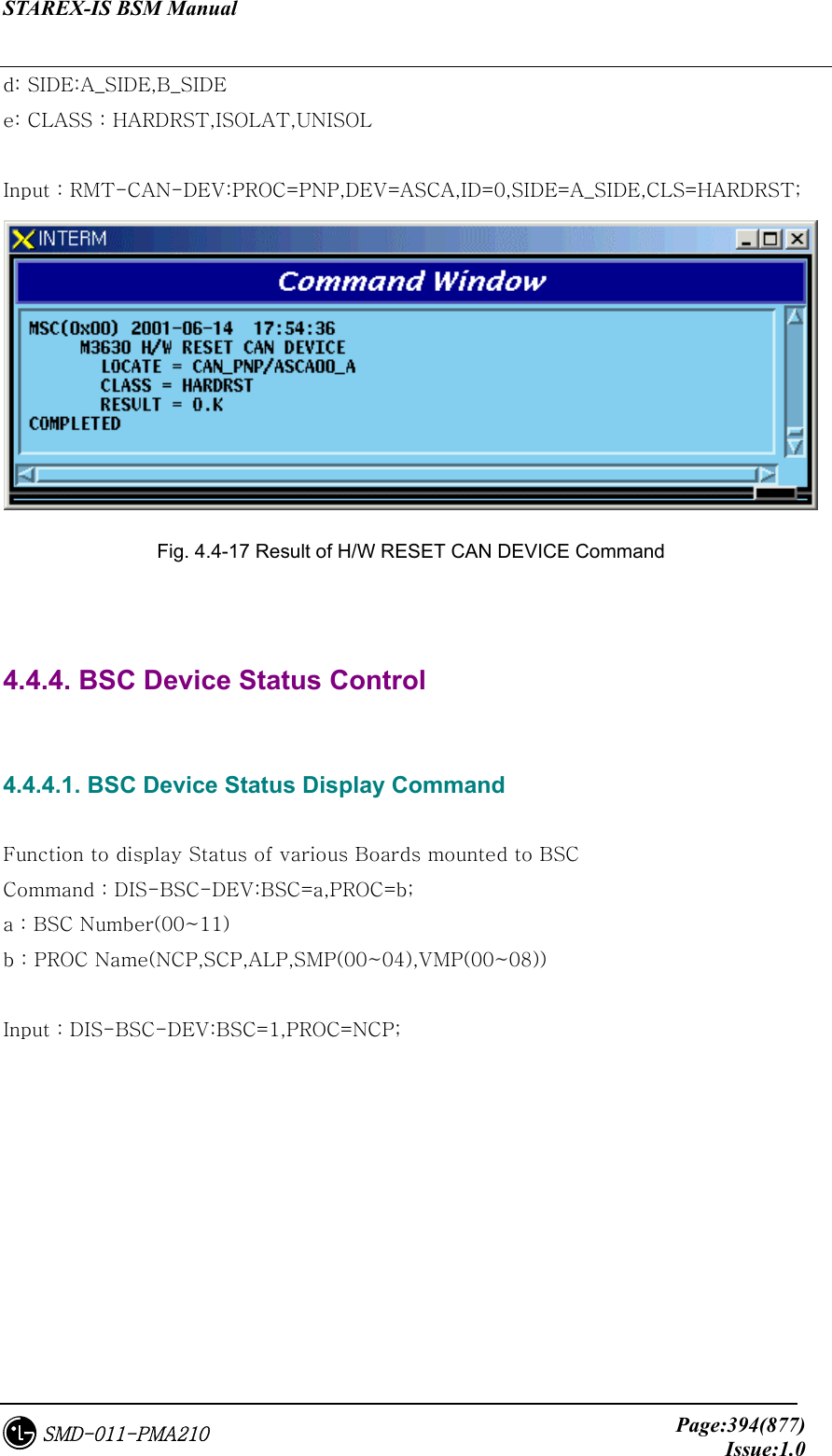
![STAREX-IS BSM Manual Page:393(877)Issue:1.0SMD-011-PMA210 Fig. 4.4-16 Result of GPS(CAN) Status Display Command 4.4.3.3. H/W RESET CAN DEVICE Command Function to reset CAN Device on H/W Level Command : RMT-CAN-DEV:PROC=a,DEV=b,ID=c,[SIDE=d],CLS=e; a: Processor :CNP,PNP,PCP(00~02),PMP(00~02) b: Device Name: ASCA,ASIA,AOTA,ATSA,PIP,FERA,FETA,BCRA c: Device ID : 0~10](https://usermanual.wiki/LG-Electronics-USA/3G1XINBTS.Users-Manual-Part-B/User-Guide-178302-Page-195.png)
![STAREX-IS BSM Manual Page:395(877)Issue:1.0SMD-011-PMA210 Fig. 4.4-18 Result of BSC Device Status Display 4.4.4.2. SLPA Status Display Command Function to display the SLPA Status Command : DIS-SLPA-STS:BSC=a,SMP=b,[SLPA=c]; a : BSC Number(00~11) b : SMP Number(00~04) c : SLPA Number(00~17) Input : DIS-SLPA-STS:BSC=0,SMP=0,SLPA=0; Fig. 4.4-19 Result of SLPA Status Display Command 4.4.4.3. VCPA Status Display Command Function to display the VCPA Status](https://usermanual.wiki/LG-Electronics-USA/3G1XINBTS.Users-Manual-Part-B/User-Guide-178302-Page-197.png)
![STAREX-IS BSM Manual Page:396(877)Issue:1.0SMD-011-PMA210 Command : DIS-VCPA-STS:BSC=a,VMP=b,[VCPA=c]; a : BSC Number(00~11) b : VMP Number(00~07) c : VCPA Number(00~15) Input : DIS-VCPA-STS:BSC=0,VMP=0,VCPA=0; Fig. 4.4-20 Result of VCPA Status Display Command 4.4.4.4. E1 LINK Status Display Command Function to display E1 Link Status of VLIA Command : DIS-E1-STS:BSC=a,VMP=b,[VLIA=c]; a : BSC Number(00~11) b: VMP Number(00~07) c: VLIA Number(00~01) Input : DIS-E1-STS:BSC=0,VMP=0,VLIA=0;](https://usermanual.wiki/LG-Electronics-USA/3G1XINBTS.Users-Manual-Part-B/User-Guide-178302-Page-198.png)
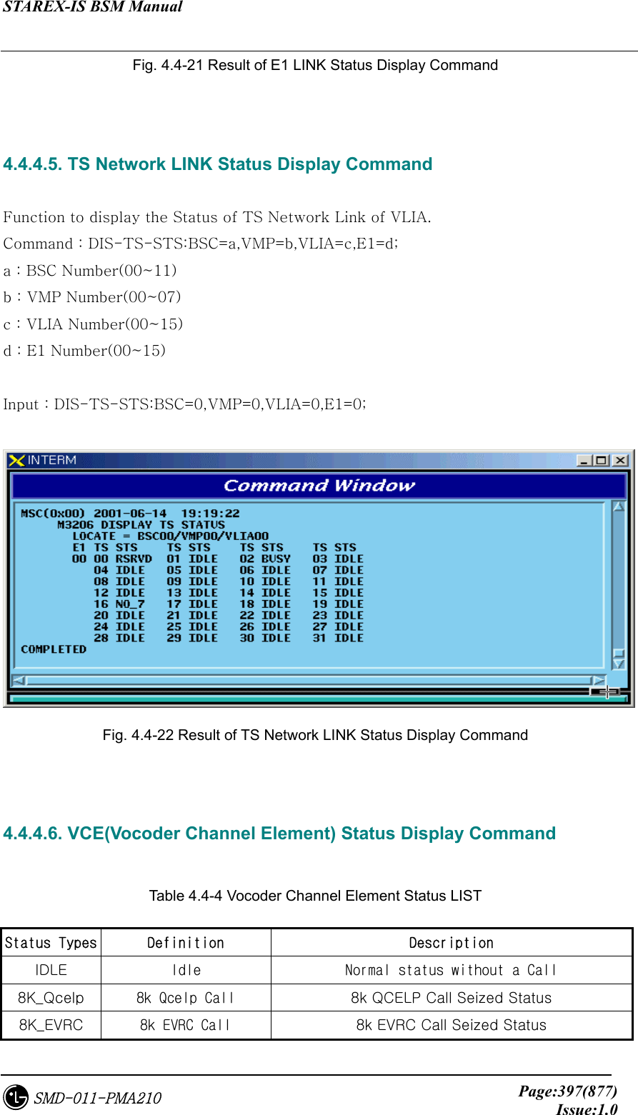
![STAREX-IS BSM Manual Page:398(877)Issue:1.0SMD-011-PMA210 13K_Qcelp 13k Qcelp Call 13k QCELP Call Seized Status 13K_EVRC 13k EVRC Call 13k EVRC Call Seized Status ABN_M Abnormal MMC Block Blocked Status by user’s MMC UNDEF Undefined Status Status with Input of undefined Status Function to display the Channel Element Status of VCE. Command : DIS-VCE-STS:BSC=a,VMP=b,[VCPA=c]; a : BSC Number(00~11) b : VMP Number(00~07) c: VCPA Number(00~15) Input : DIS-VCE-STS:BSC=0,VMP=0,VCPA=0; Fig. 4.4-23 Result of VCE(Vocoder Channel Element) Status Display Command 4.4.4.7. SLPA BLOCK Command Function to block SLPA. Command : BLK-SLPA:BSC=a,SMP=b,SLPA=c,[SLV=d]; a : BSC Number(00~11) b : SMP Number(00~04) c : SLPA Number(00~17) d : SLV Number(00~03) Input : BLK-SLPA:BSC=0,SMP=0,SLPA=0,SLV=0;](https://usermanual.wiki/LG-Electronics-USA/3G1XINBTS.Users-Manual-Part-B/User-Guide-178302-Page-200.png)
![STAREX-IS BSM Manual Page:399(877)Issue:1.0SMD-011-PMA210 Fig. 4.4-24 Result of SLPA BLOCK Command 4.4.4.8. SLPA UNBLOCK Command Function to unblock SLPA. Command : UBLK-SLPA:BSC=a,SMP=b,SLPA=c,[SLV=d]; a : BSC Number(00~11) b : SMP Number(00~04) c : SLPA Number(00~17) d : SLV Number(00~03) Input : UBLK-SLPA:BSC=0,SMP=0,SLPA=0,SLV=0; Fig. 4.4-25 Result of SLPA UNBLOCK Command 4.4.4.9. VCPA BLOCK Command Function to block VCPA. Command : BLK-VCPA:BSC=a,VMP=b,VCPA=c,[SLV=d],[DSP=e]; a : BSC Number(00~11)](https://usermanual.wiki/LG-Electronics-USA/3G1XINBTS.Users-Manual-Part-B/User-Guide-178302-Page-201.png)