LG Electronics USA 3G1XINBTS STAREX-IS 1900 Indoor BTS User Manual STAREX IS User s Manual
LG Electronics USA STAREX-IS 1900 Indoor BTS STAREX IS User s Manual
UserManual.wiki
>
LG Electronics USA
>
3G1XINBTS User Manual
>
Users Manual Part F
Contents
1.
Users Manual Part A
2.
Users Manual Part B
3.
Users Manual Part C
4.
Users Manual Part D
5.
Users Manual Part E
6.
Users Manual Part F
7.
Users Manual Part G
Users Manual Part F
Navigation menu
Upload a User Manual
Namespaces
Wiki Guide
HTML
PDF
Info
Views
User Manual
Discussion / Help
Navigation


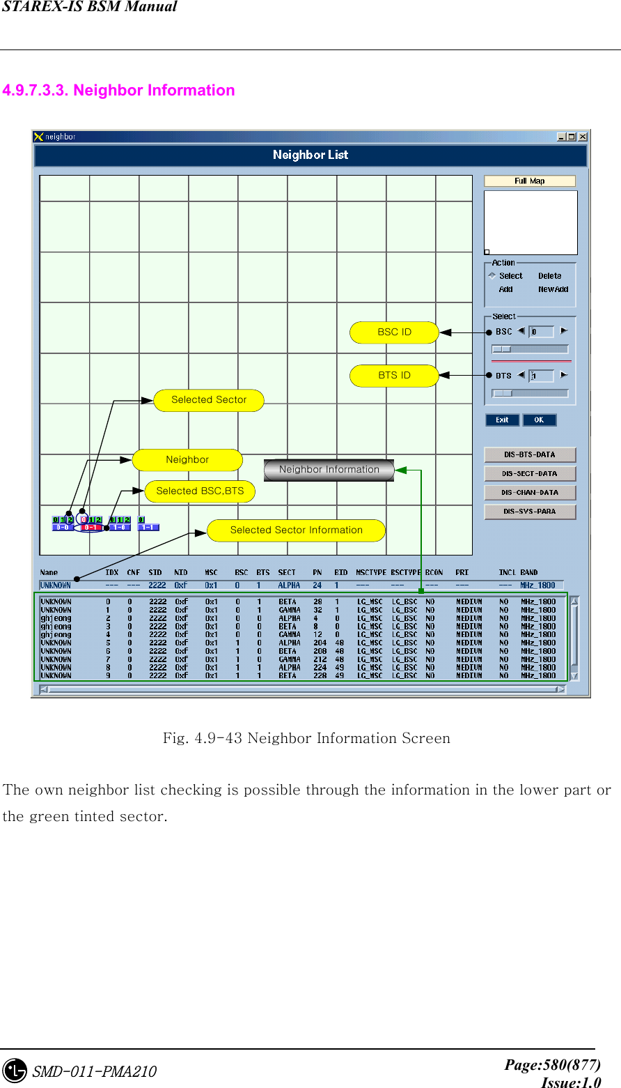
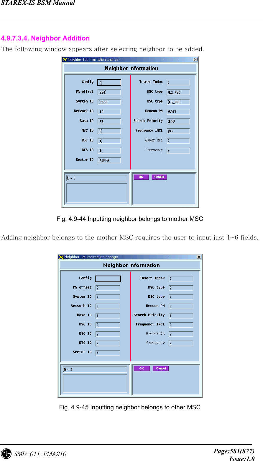
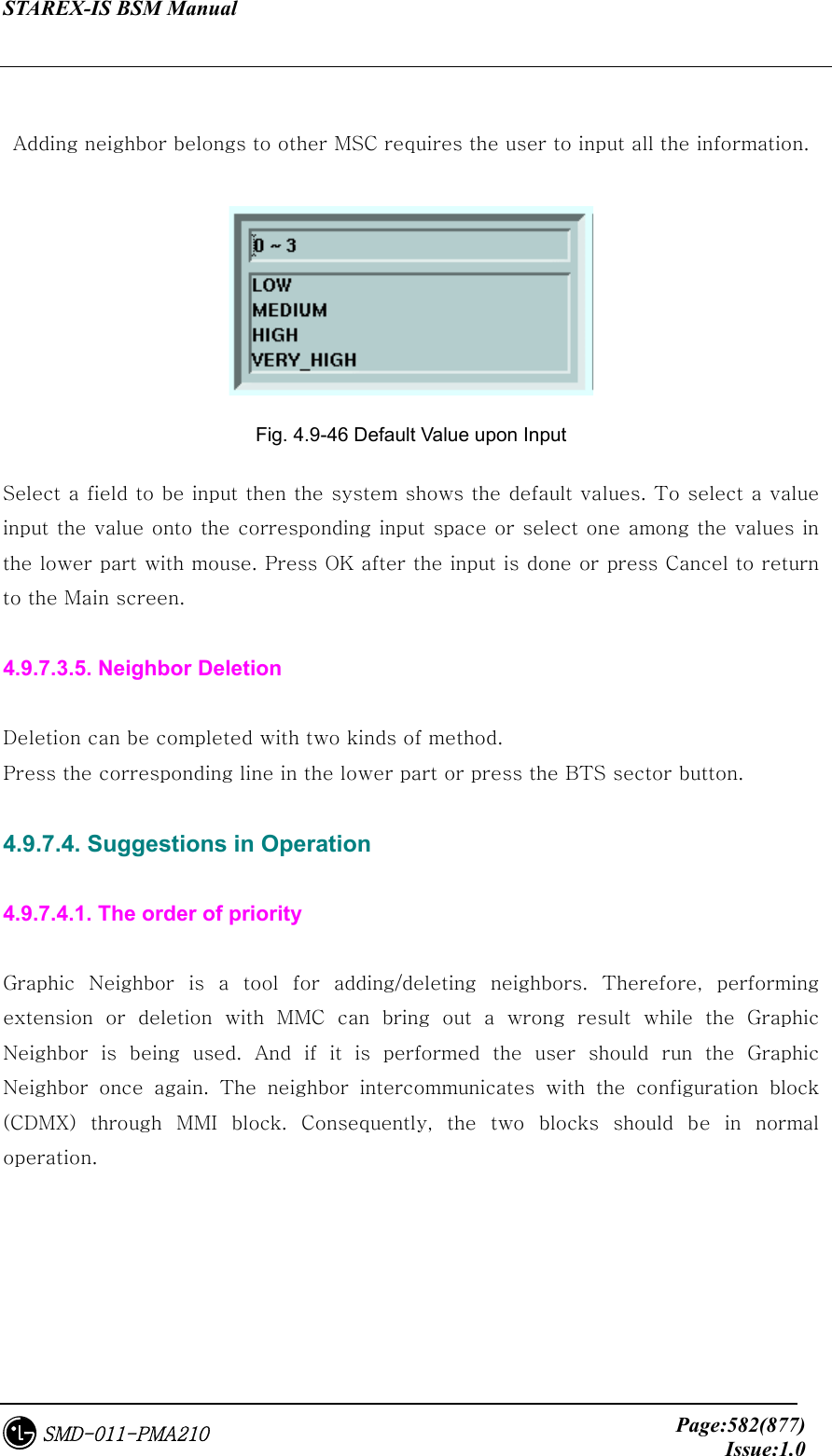
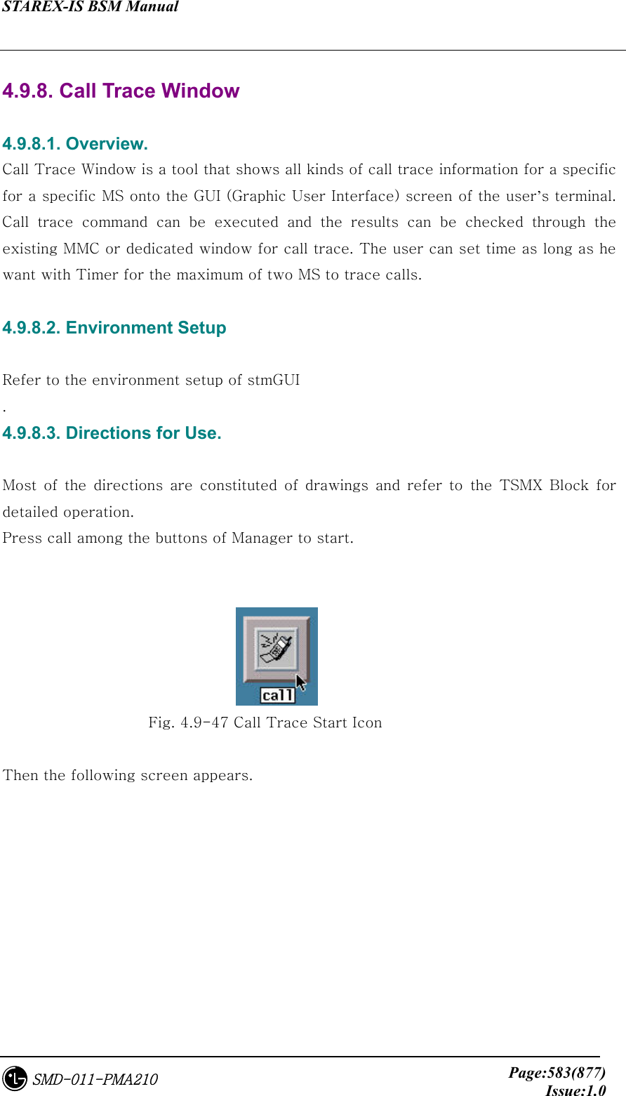
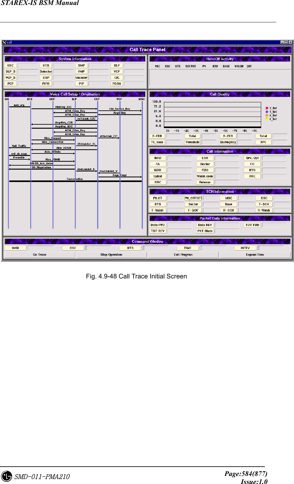
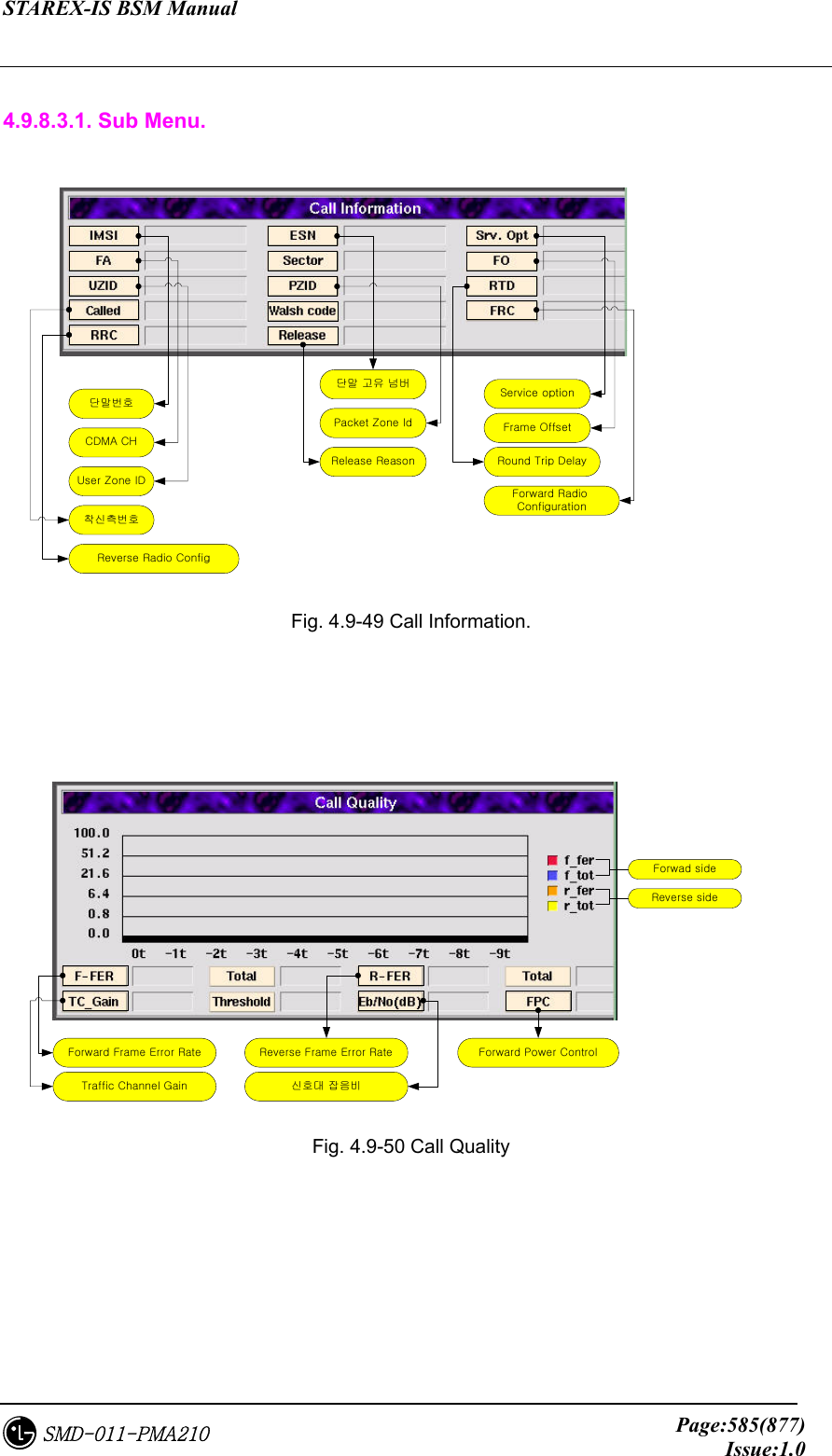
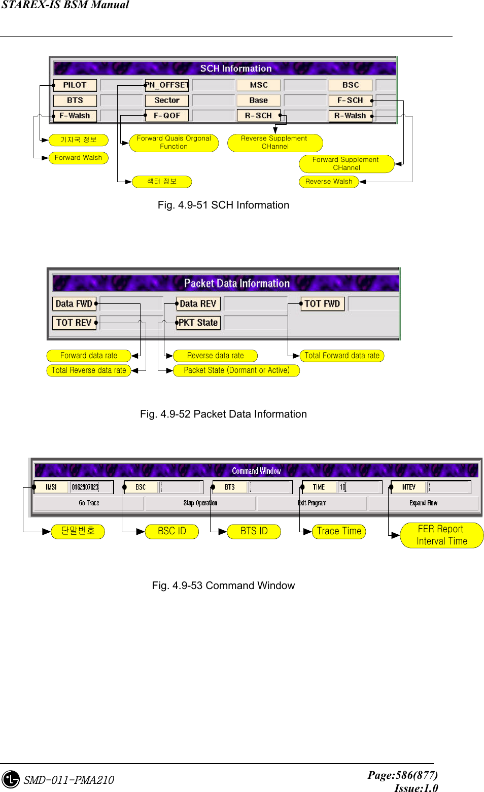
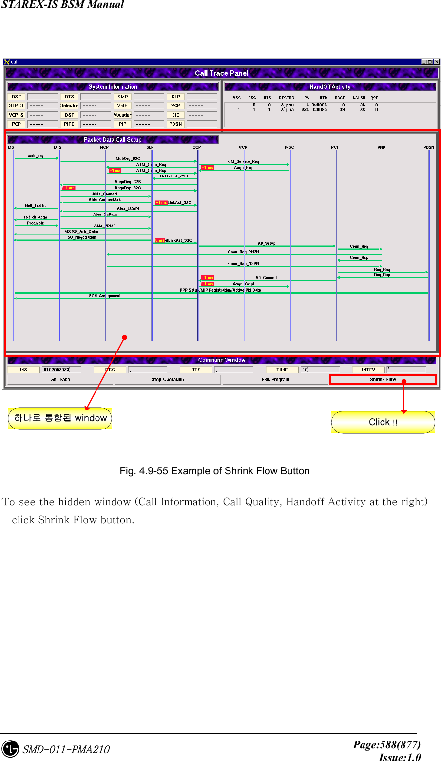
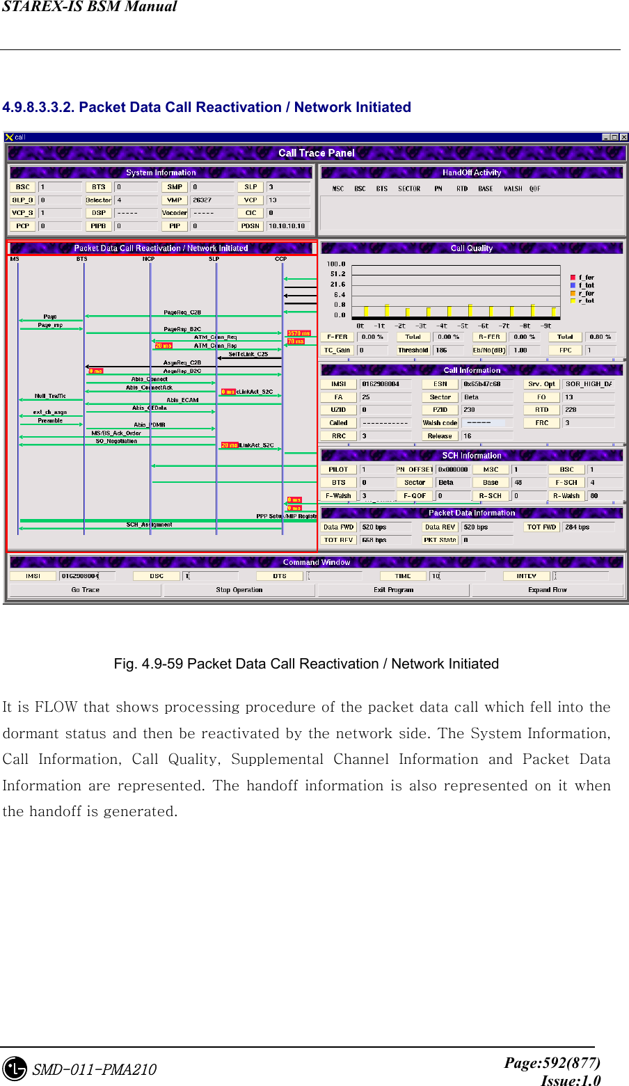
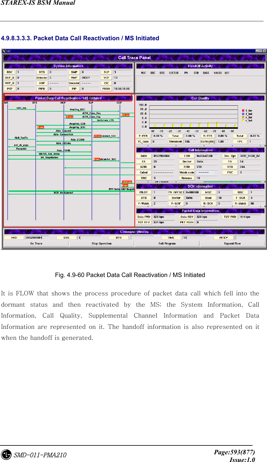
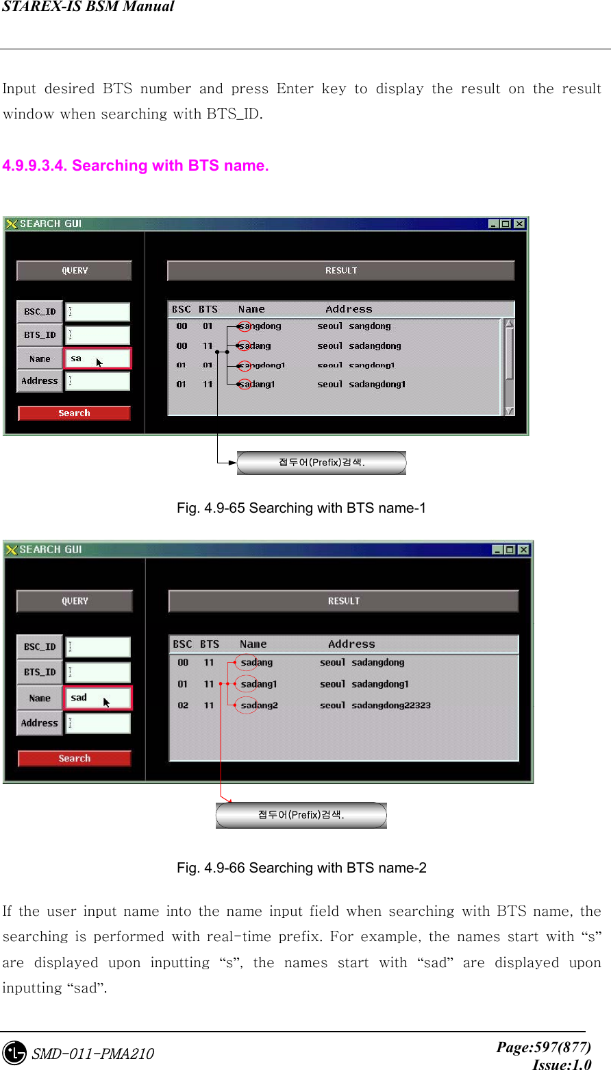
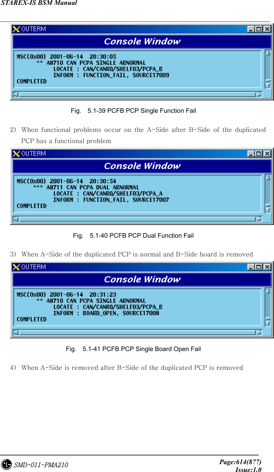
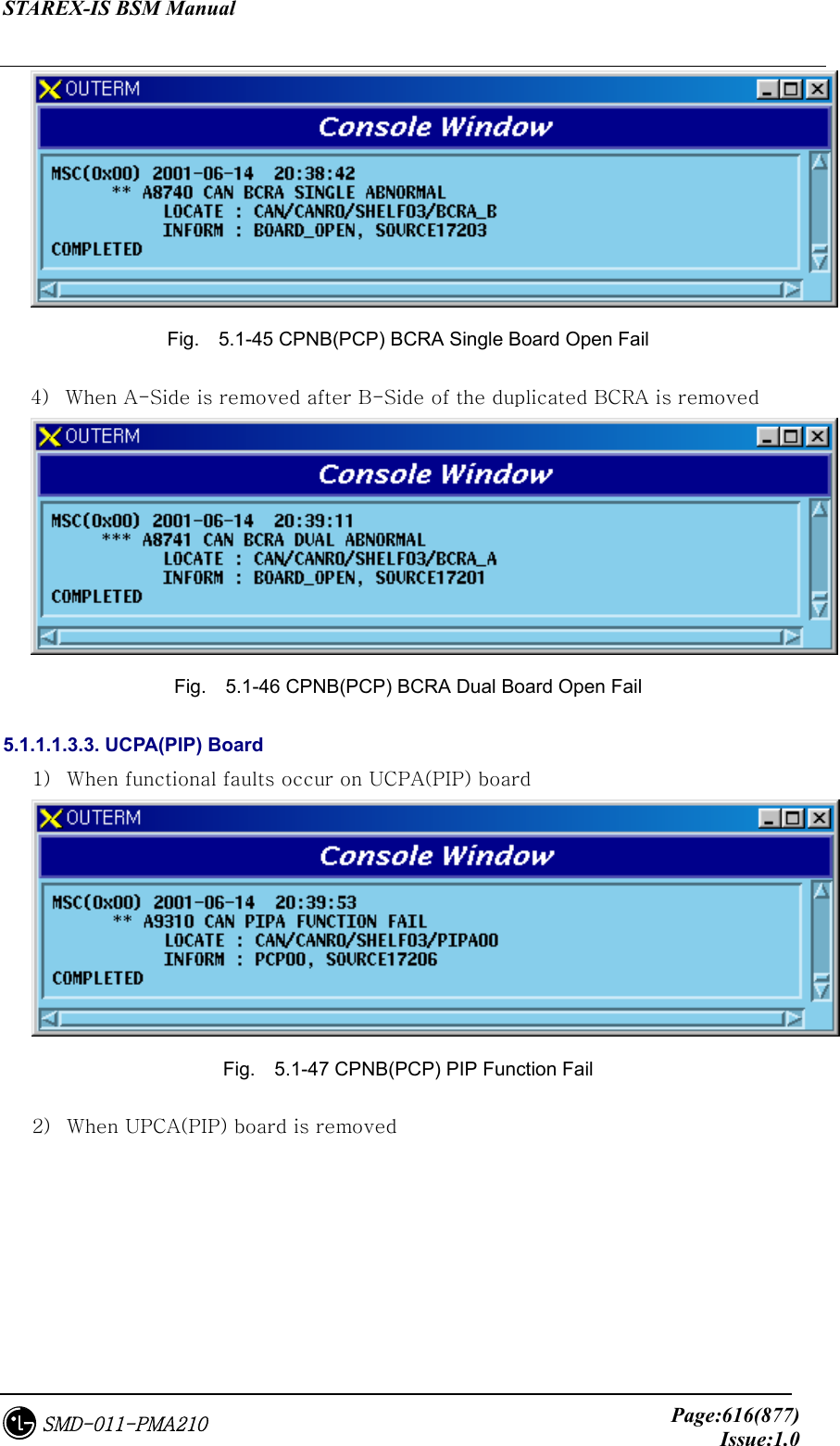
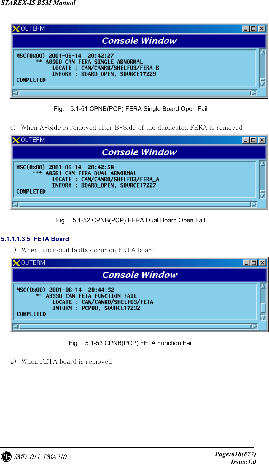
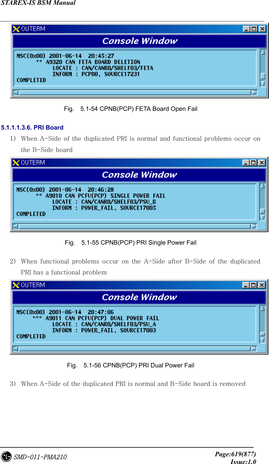
![STAREX-IS BSM Manual Page:587(877)Issue:1.0SMD-011-PMA210 Input MS number (IMSI), BSC ID, BTS ID, Trace Time and FER Report Interval Time into the command window of [Fig. 4.8-53], and press Go Trace button below, then the call trace starts. Press Stop Operation beside Go Trace button to stop the process during the operation and press Exit Program to end call trace program. The Expand Flow shows the flow to the PDSN upon clicking it. Click !!2개로 분할된 window Fig. 4.9-54 Example of Expand Flow Button If the user wants to see the expand flow hidden by the window at the right side after call test, click Expand Flow button to see the expand flow.](https://usermanual.wiki/LG-Electronics-USA/3G1XINBTS.Users-Manual-Part-F/User-Guide-178306-Page-39.png)