LG Electronics USA 3G1XINBTS STAREX-IS 1900 Indoor BTS User Manual STAREX IS User s Manual
LG Electronics USA STAREX-IS 1900 Indoor BTS STAREX IS User s Manual
Contents
Users Manual Part F
STAREX-IS BSM Manual
Page:549(877)
Issue:1.
0
SMD-011-PMA210
Fig. 4.9-4 CDM Tear-off
4.9.2.4. Operation Command and Usage.
All commands are available in the pop-up menu with mouse as followed and also
available by inputting command manually on the INPUT WINDOW depending upon
command grammar like using shell command in UNIX.
4.9.2.4.1. Command Input Method using POP-UP MENU
Fig. 4.9-5 POP-UP window
Parameter
입력필드
사용자가
원하는
Parameter
의
값을
입력하는
창이다
Parameter
도움말
Parameter
의
유효값의
범위가
이창에
나타난다
Cancel Button
사용자가
이
작업을
취소
시키고자
할때
이
버튼을
누른다
Option Name
사용자가
입력할
옵션의
이
름으로
검정색은
반드시
입
력을
받아야하며
파랑색은
입력을
생략해도
된다
Message Display
Window-
The error message
appears here when invalid
parameter
value is input
Ok Button
사용자가
parameter
입력을
끝내고
작업을
수행하고자
할때
누른다
메뉴타이틀
사용자가
내린
명령어를
타이틀에
표시
해준다
Parameter Input Field
- Input parameter
value upon
user’s demand
Parameter Tip
-Valid parameter
value appears
Cancel Button
-Canceling the
operation by the user
Option
Name –
User’s input option name.
Black should be input Blue
one is can
be omitted
Ok Button-
When starting operation after
inputting parameter value
Menu Title - User
’s
command is on the title
STAREX-IS BSM Manual
Page:550(877)
Issue:1.
0
SMD-011-PMA210
4.9.3. Batch Job
It is the function to make commands operate depending on the set value by reserving
the MMC at the user’s definition for the user’s convenience.
4.9.3.1. Batch Job Window Configuration
The window is divided into the following three parts by the characteristics of the
work: batch job set part, batch job list and command list, menu part.
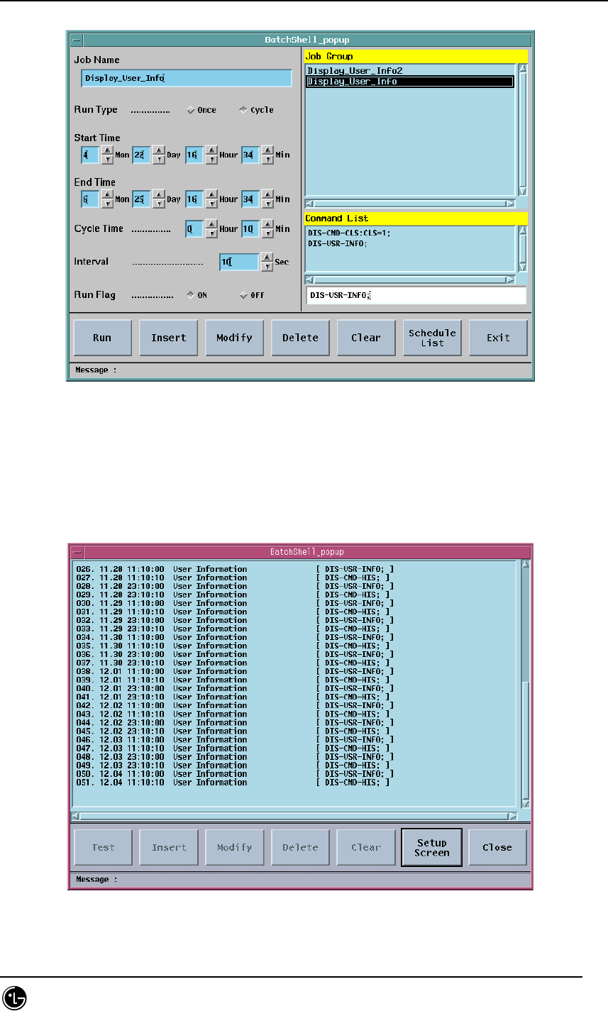
Fig. 4.9-6 Batch Job Screen
4.9.3.2. Run Batch Job
The batch job menu is included in the IO sub-menu, and just one batch job can be
executed in one workstation. If the batch job is authorized, the menu is displayed in
the executable status; if the batch job is already under execution the system prevents
the overlapping of the work by making the menu ‘Disable’. That is, the menu can be
run on the interm run with bim; the menu always is ‘Disable’ upon remote access using
telnet or rlogin; the menu can be run upon client access using the pcsnet because it
uses local DB.

STAREX-IS BSM Manual
Page:551(877)
Issue:1.
0
SMD-011-PMA210
.
4.9.3.3. Batch Processing Set Area
Job Name
It is the name of the work to be set and added into the Job Group when storing. The
maximum length of the name is restricted into 40 letters.
Run Type
Set if the work to be operated with a cycle, or at the specific time. (ONCE, CYCLE)
Start Time
It is the starting time of the work and the present time of the system is filled in the
data field as a basic value.
End Time
It is the ending time of the work and the next date for the present time of the system
is filled in the data field as a basic value. If the ending time has passed the present
time it takes the Run Flag off.
Cycle Time
It designates the hour and minute to execute the next command when the Run Type is
set as Cycle.
Interval
It is the time between each command represented in seconds (1~6000) when several
commands are input in single work name. Interval over 5sec is recommended.
Run Flag
It represents whether the set batch processing is executed. (ON, OFF)
List Area
Job Group
It is the list of registered works and the key value, which controls DB.
Command List
It is the list of commands for single work. Maximum four commands can be input.
Command Input Text Field
It is the field on which the command is input.
4.9.3.4. Menu Field
Test
It is the menu to test if the command for the presently selected work or the work for
which the input is performed is input without error.
Insert

STAREX-IS BSM Manual
Page:552(877)
Issue:1.
0
SMD-011-PMA210
It is the menu to input new work.

STAREX-IS BSM Manual
Page:553(877)
Issue:1.
0
SMD-011-PMA210
Modify
It is the menu to modify the previously input work.
Delete
It is the menu to delete the input work or the command in the command list.
Clear
It is the menu to remove the values left in the data field.
Schedule List/Setup Screen
It shows the schedule list presently on the execution standby status.
Exit/Close
It is the menu to close the batch job window.
4.9.3.5. Message Display Area
Error message on operation and messages for alarm and status change are displayed.
STAREX-IS BSM Manual
Page:554(877)
Issue:1.
0
SMD-011-PMA210
4.9.3.6. Batch Job Operation
4.9.3.6.1. Open Window
Select IO menu of “INTERM”, which is command I/O window, and click Batch Job then
the window is opened.
4.9.3.6.2. Job Input
Job name is the key value that controls DB so it should be the one and only value.
When selecting insert menu it would not be stored unless the job name is input. The
data field restricts the number of letters when inputting the data; emits alarm sound
when it is exceeded. The figure input part is configured with the field in which the
figure can be input manually and the buttons that change the figures. The maximum
and minimum value is designated so if the figure exceeds this scope, it is set as a
minimum value; if a letter is input the system emits alarm sound. After one command is
input in the command input field, press ‘Enter’ key then it added into the command list.
If a wrong command is added, select the list and press ‘Delete’ menu then it will be
deleted.
Fig. 4.9-7 Batch Job Input

STAREX-IS BSM Manual
Page:555(877)
Issue:1.
0
SMD-011-PMA210
After the input is completed, check if it is set with correct values and choose ‘Insert’
menu.
STAREX-IS BSM Manual
Page:556(877)
Issue:1.
0
SMD-011-PMA210
4.9.3.6.3. Job Modifying
The job modification takes the same method with the input but the job name operates
the key of DB cannot be modified.
Fig. 4.9-8 Batch Job Modification
After modifying, input ‘Modify’ menu by all means, so as that the modification is
completed.
4.9.3.6.4. Job Deletion
Use ‘Delete’ menu with great care because it has two functions: deleting job group and
deleting command list. Choose ‘Delete’ menu after selecting job group list then the
chosen job will be deleted; press ‘Delete’ menu after selecting command group then
the command will be deleted. Choose ‘Modify’ once more when deleting command so
as to delete the command completely and store the content into the DB.
STAREX-IS BSM Manual
Page:557(877)
Issue:1.
0
SMD-011-PMA210
Fig. 4.9-9 Batch Job Deletion
4.9.3.6.5. Job Status Display
This menu shows the set jobs with their schedule. This menu shows setup window and
schedule list by converting them with toggle method.
Fig. 4.9-10 Batch Job Status Display
STAREX-IS BSM Manual
Page:558(877)
Issue:1.
0
SMD-011-PMA210
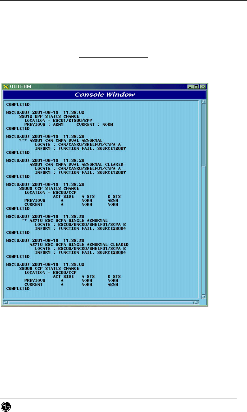
4.9.4. Console Window
4.9.4.1. Overview
It is the window displaying event list of processor and also displays status change
alarm and alarm information.
Fig. 4.9-11 Console Window
4.9.4.2. Operation
The console window displays system message, supports pop-up menu and its display
environment is adjustable. It is divided into background color, text color, text font, text
STAREX-IS BSM Manual
Page:559(877)
Issue:1.
0
SMD-011-PMA210
size and close; press mouse button 3 to operate this function then the operating menu
pops up. The number of message to be displayed is uncertain depending upon system
load but roughly 400 through 800 messages can be displayed per second.
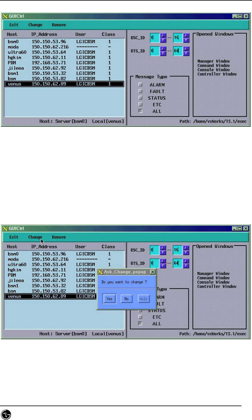
4.9.5. Controller
4.9.5.1. Overview
As the GUI gets complicated and varied the control for GUI is needed. Therefore,
place a controller to control the entire GUI with close relation to their connection.
Furthermore, due to the supply of network environment the user can access to a
system more easily; the control is more complicated; monitor equipment to monitor
and control them is needed; so the equipment to control the network and message
display is developed.
The controller manages the host accessing to BMS Server; controls the display
message of BSC, BTS, and Message Type; is in charge of process management.
4.9.5.2. Operation
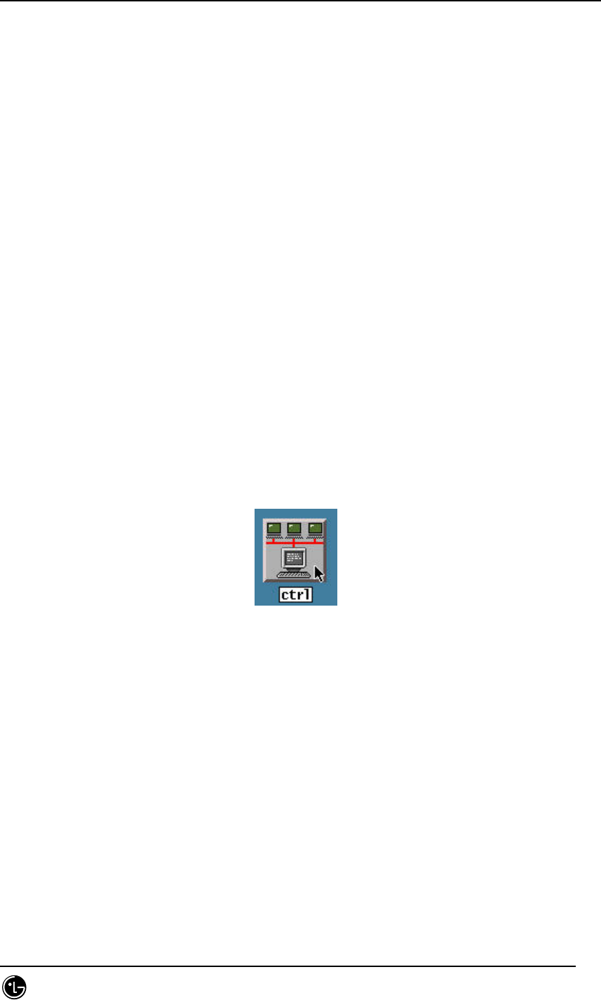
Press ctrl among the buttons in Manager to start operation.
Fig. 4.9-12 ctrl Start Icon
Then the following screen is displayed.
The controller is divided into two parts of network control and message control.
STAREX-IS BSM Manual
Page:560(877)
Issue:1.
0
SMD-011-PMA210
Fig. 4.9-13 Controller Window
4.9.5.3. Message Filtering
The message control function is only supplied to the host, and it can filter and display
the message of particular BTS or specific part. The message type is sorted into
ALARM, FAULT, STATUS, and ETC. If the message type is not defined display the ‘all
message display’.
Fig. 4.9-14 Message Filtering of Controller
4.9.5.4. Network Management
The network control is the function provided by the BMS server and supplies the
following functions: checking the host name of presently accessed client, address, user,
STAREX-IS BSM Manual
Page:561(877)
Issue:1.
0
SMD-011-PMA210
user’s grade, and message display information and compulsory expulsion of them. The
client can display the hosts presently in operation but cannot control the other users
except its host.
Fig. 4.9-15 Network Management of Controller
4.9.5.5. Suggestions
This program refers to the /etc/hosts file, so IP_Address, Domain_name, and
Alais_name should be correctly recorded fit for the network configuration information.
4.9.6. Status Window (stmGUI)
4.9.6.1. Overview
The user can use the MMC (DIS-*-STS, DIS-*-ALM, DIS-*-FLT) to investigate the
status of processor, board and alarm occurrence in each BSC/BTS. However, the user
should keep on inputting commands with keyboard or mouse to check it on real-time;
moreover, it is hard for the user to grasp the whole situation at one sight; therefore,
the system takes advantage of the GUI(Graphic User Interface) to help the user in
operation and for the more efficient system management.
4.9.6.2. Environment Setup
Solaris 2.7 and CDE library are used to develop the BMS as the OS and Graphic library.
Moreover the Window Manager is set to be performed under CDE (Common Desktop
Environment). Therefore, the user would be in a good operational environment if he
operates the system on the environmental ground above (refer to the set and

STAREX-IS BSM Manual
Page:562(877)
Issue:1.
0
SMD-011-PMA210
environment set).

STAREX-IS BSM Manual
Page:563(877)
Issue:1.
0
SMD-011-PMA210
4.9.6.2.1. Suggestions
LD_LIBRARY_PATH is one of the most important environment variables. The stmGUI
could be down during the operation unless the user let the stmGUI search
/usr/X11R5/lib first of all.
e.g.) setenv LD_LIBRARY_PATH /usr/dt/lib/:usr/openwin/lib/:/usr/lib
4.9.6.2.2. Data Files
If the stmGUI is unable to be run, the needed data files could be non-existed.
Therefore, check if the following files are in the DATA/GUI Directory.
RACK.DAT : file contains the shape of RACK .
SHELF.DAT : file contains the shape of SHELF.
PROCESS.DAT: definition file of the processors.
*.xpm : drawing files needed in screen processing.
bts_name.info : files contain BTS name.
STAREX-IS BSM Manual
Page:564(877)
Issue:1.
0
SMD-011-PMA210
4.9.6.3. Directions for Use
The direction is configured with full of drawings. Refer to the STMX, TRMX Block for
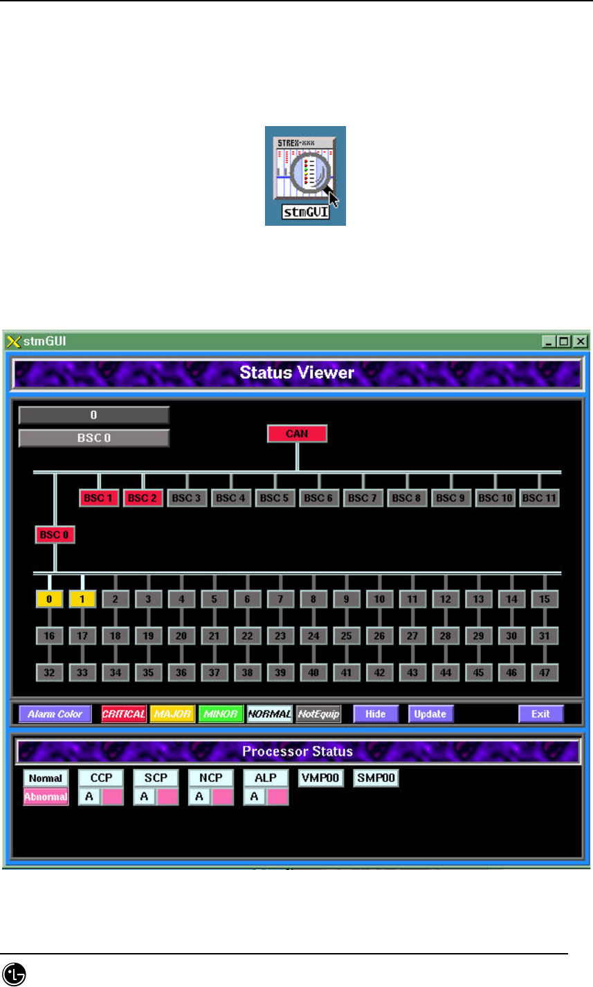
detailed operation. Press stmGUI among the buttons of Manager.
Fig. 4.9-16 stmGUI Start Icon
Then the following screen is displayed.
Fig. 4.9-17 stmGUI Main Screen
STAREX-IS BSM Manual
Page:565(877)
Issue:1.
0
SMD-011-PMA210
The figure above shows the status that the highest-grade alarm of the BSC0 is the
critical alarm and the highest alarm of the BTS0, major alarm, is generated.
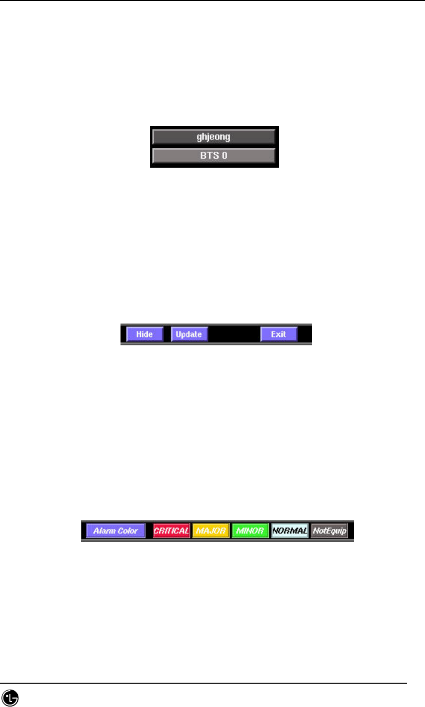
4.9.6.3.1. BTS Name Display.
Fig. 4.9-18 Display Screen of BTS Name.
e.g.) On the figure above, ghjeong is the real name of the BTS and BTS 0 is the BTS
ID.
4.9.6.3.2. Main Menu
Fig. 4.9-19 Main Menu
Hide : It is used when hiding RACK and SHELF simultaneously from the screen.
Update : It is used in compulsory loading of initial value upon deletion and extension
by MMC.
Exit : It ends the program.
4.9.6.3.3. Color by the Alarm Grade
Fig. 4.9-20 Alarm Color
Red : Critical
Orange : Major
Green : Minor
Azure : Normal

STAREX-IS BSM Manual
Page:566(877)
Issue:1.
0
SMD-011-PMA210
Gray : BTS Is Not Equipped
STAREX-IS BSM Manual
Page:567(877)
Issue:1.
0
SMD-011-PMA210
4.9.6.3.4. Status Color.
Fig. 4.9-21 Status Color Tone
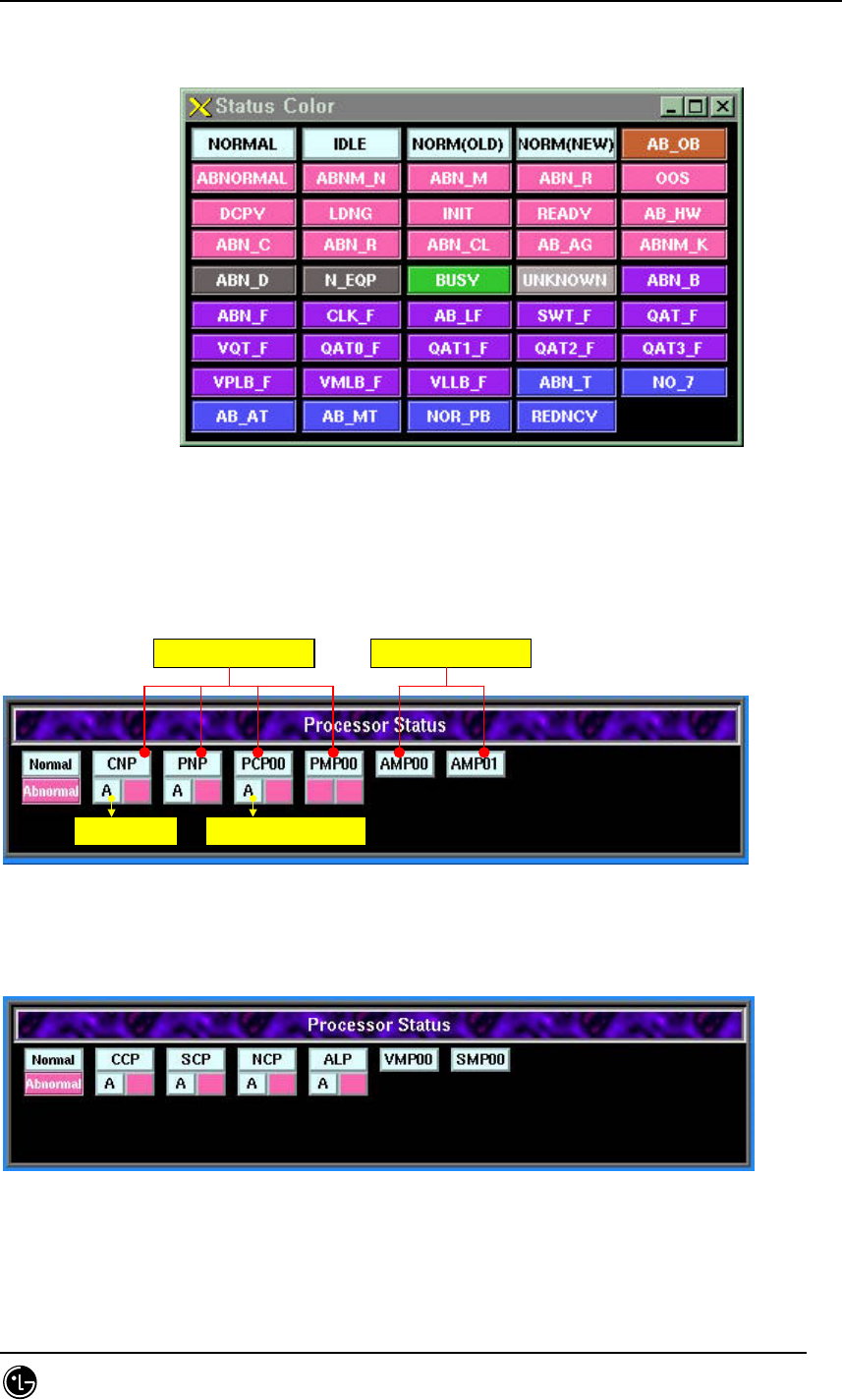
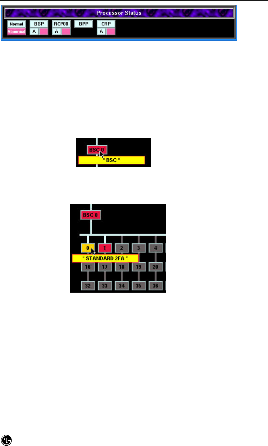
4.9.6.3.5. Processor Status
Fig. 4.9-22 Processor Status (CAN)
Fig. 4.9-23 Processor Status (BSC)
Normal A Side Active
Dual Processor Single Processor
Normal A Side Active
Dual Processor Single Processor
STAREX-IS BSM Manual
Page:568(877)
Issue:1.
0
SMD-011-PMA210
Fig. 4.9-24 Processor Status (BTS)
4.9.6.3.6. Rack View
To see the shape of BSC/BTS one should press the corresponding button.
Select a BSC.
Fig. 4.9-25 BSC Selection
Select a BTS.
Fig. 4.9-26 BTS Selection
STAREX-IS BSM Manual
Page:569(877)
Issue:1.
0
SMD-011-PMA210
.
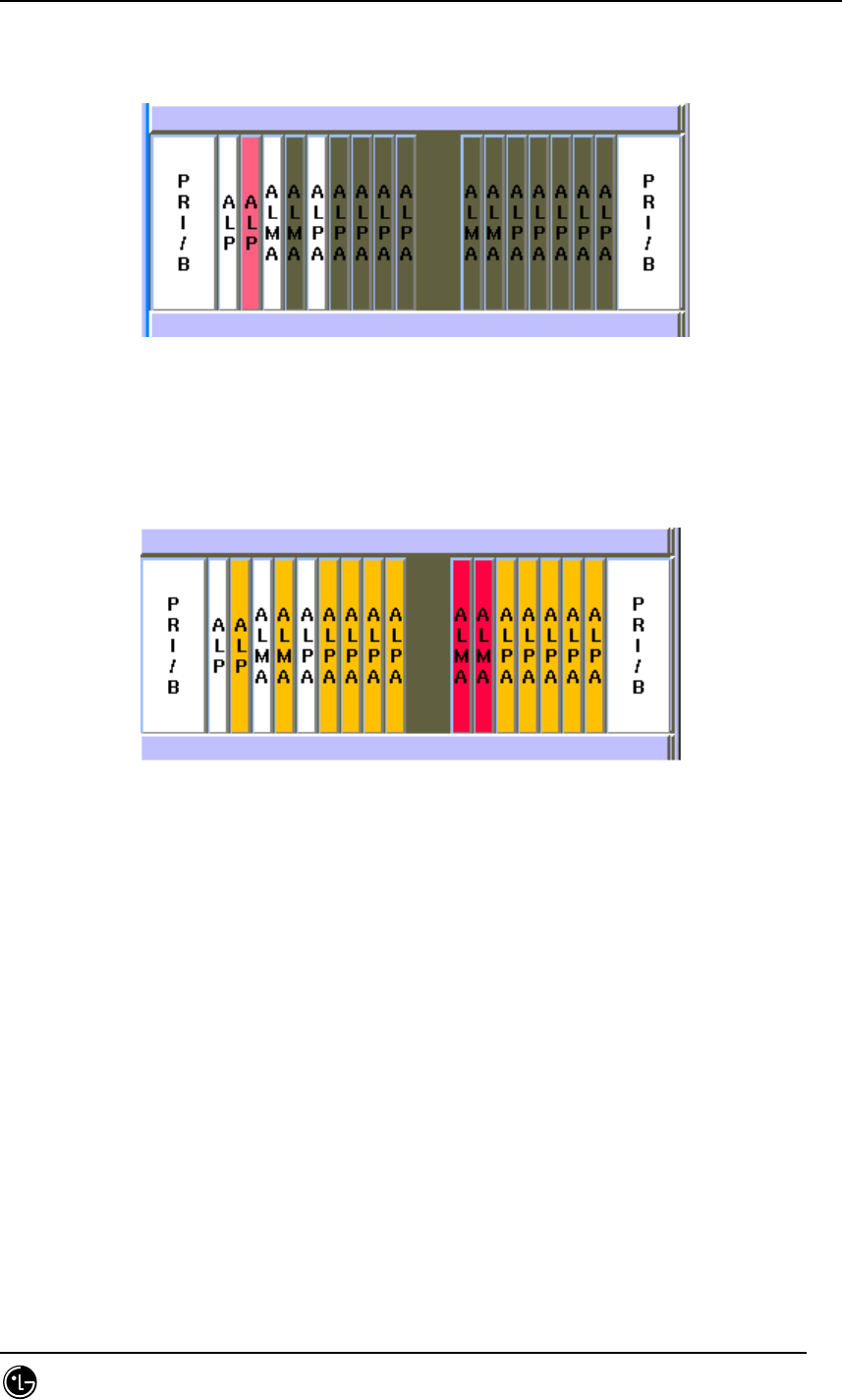
4.9.6.3.7. Rack Shape Diagram.
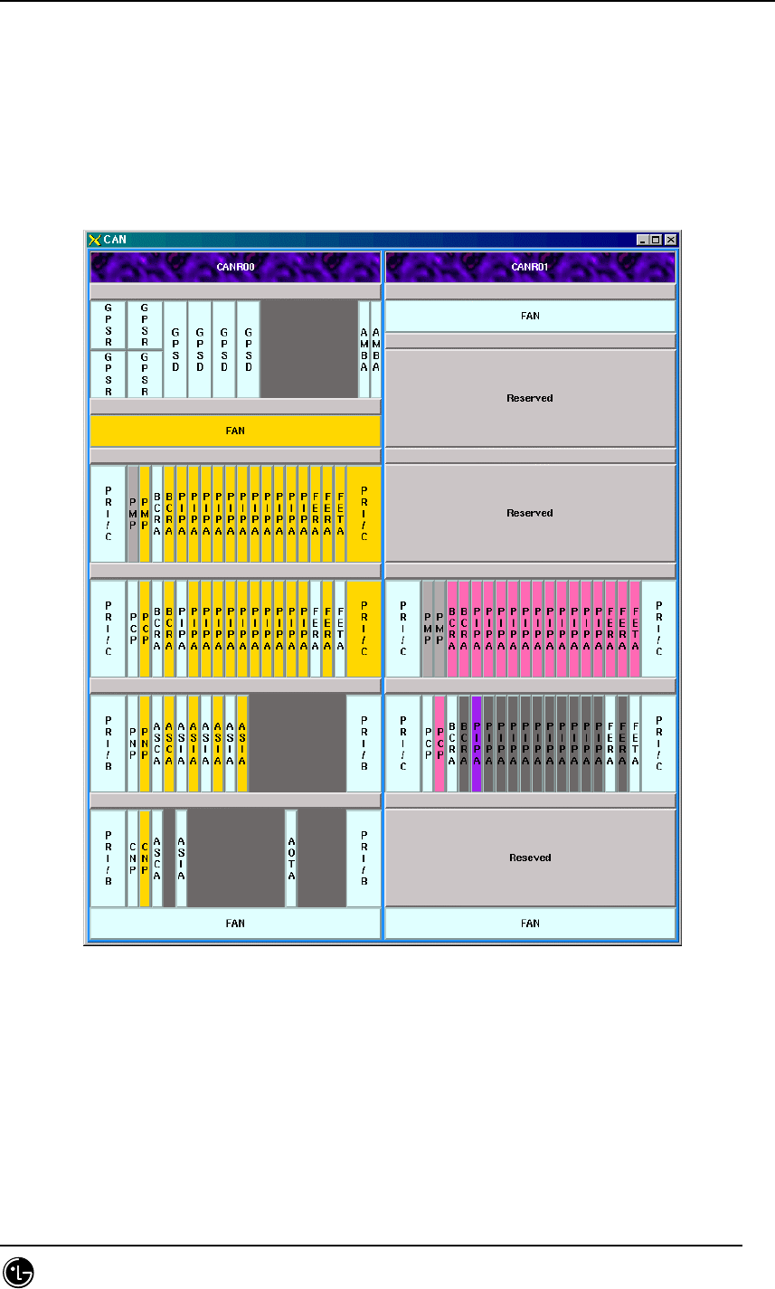
The following shape appears if CAN, BSC or BTS is chosen.
4.9.6.3.7.1. CAN Rack
Fig. 4.9-27 CAN Rack Shape.
The color of each slot manifests the alarm information of equipped cards. For example,
the yellow color of BCRA, PIPA and FERA in the 4th shelf of the left side shows that
the alarm is generating at Major status.
STAREX-IS BSM Manual
Page:570(877)
Issue:1.
0
SMD-011-PMA210
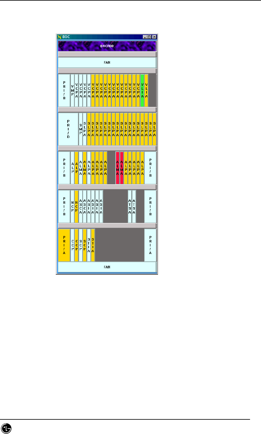
4.9.6.3.7.2. BSC Rack
Fig. 4.9-28 BSC Rack
STAREX-IS BSM Manual
Page:571(877)
Issue:1.
0
SMD-011-PMA210
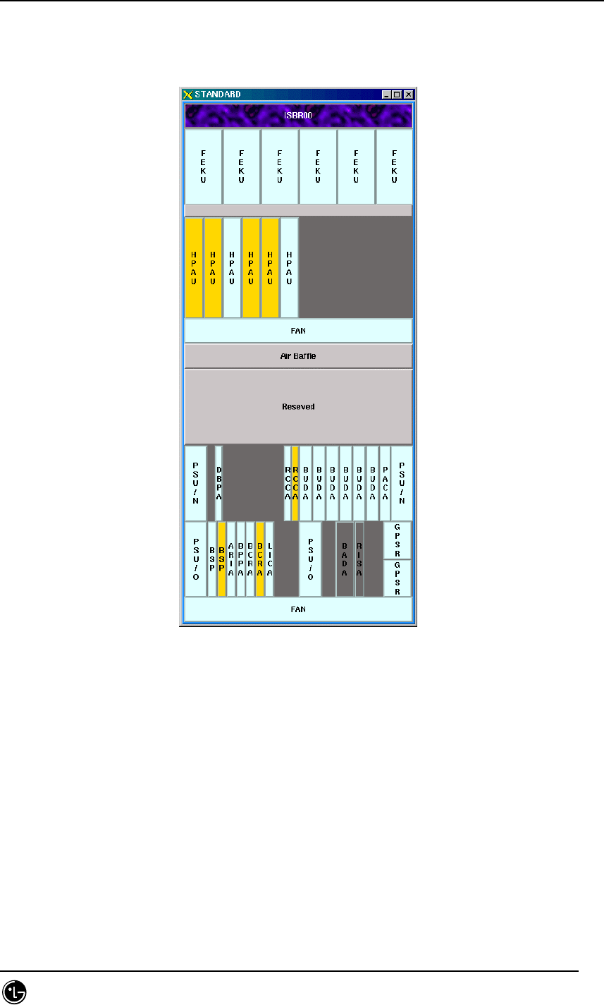
4.9.6.3.7.3. BTS Rack
Fig. 4.9-29 BTS Rack
STAREX-IS BSM Manual
Page:572(877)
Issue:1.
0
SMD-011-PMA210
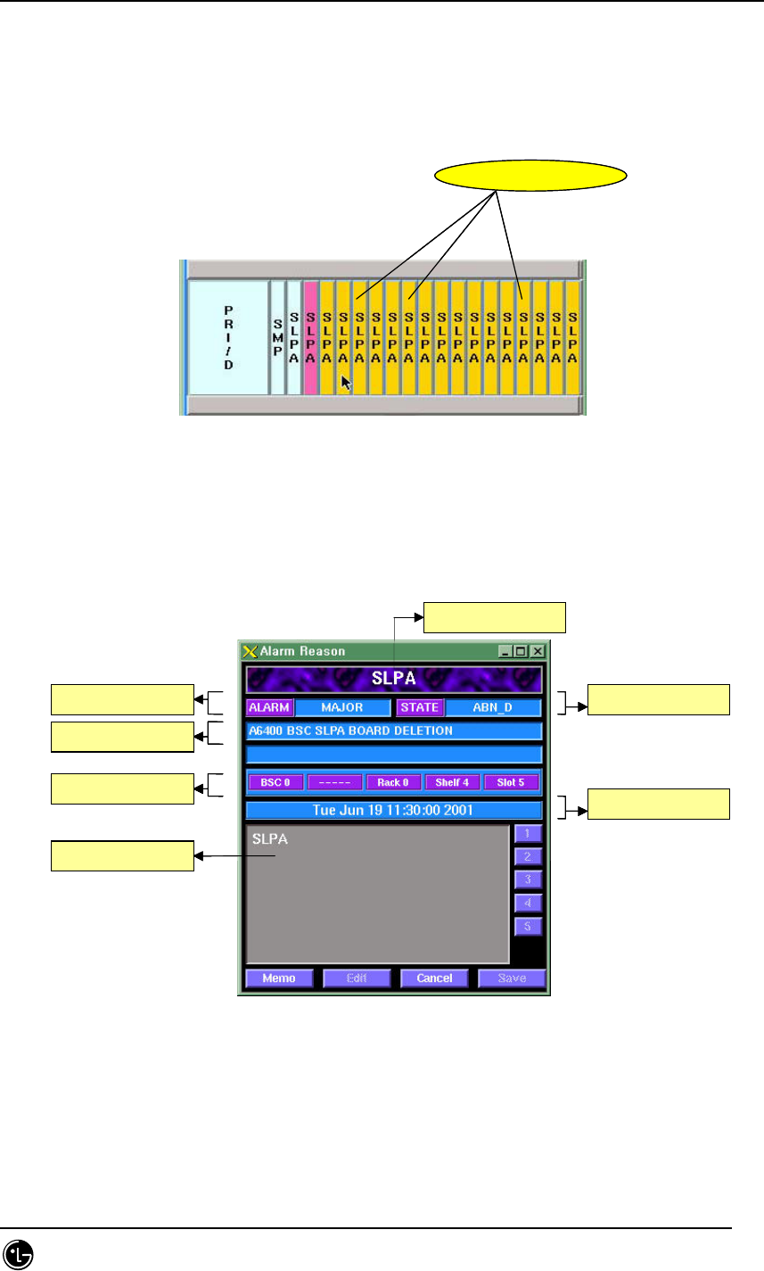
4.9.6.3.7.4. Slot Shape Diagram.
The corresponding dialog box is displayed upon clicking slot in the rack shape diagram.
Fig. 4.9-30 card click example.
The following dialog box appears upon clicking SLPA card above.
Fig. 4.9-31 e.g.)Dialog box- card Information
Memo: Stores the edited results temporarily.
Edit: Edit button
clickclick
Alarm
정보
상태
정보
Board name
Alarm message
형상
위치
정보
Time
memo
Alarm
Info
상태
정보
Status Info
Board name
Alarm messageAlarm message
형상
위치
정보
Shape Location Info
TimeTime
memo
STAREX-IS BSM Manual
Page:573(877)
Issue:1.
0
SMD-011-PMA210
Cancel: End button
Save: Stores the edited.
1,2,3,4,5 button: The memo is stored in numerical order.
Click numbers in right side(1,2,3,4,5) to see the memo.
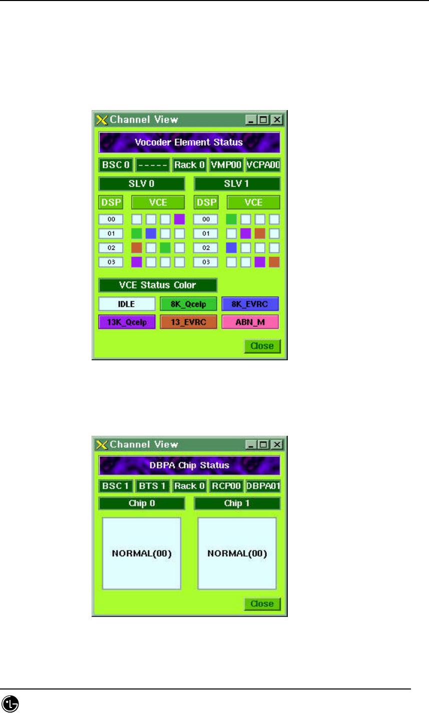
Fig. 4.9-32 e.g.)Dialog box-Vocoder Element Status
For example, the SK_Qcelp type call in the VCE0 of DSP1 is in busy status.
Fig. 4.9-33 e.g.)Dialog box-DBPA Chip Status
STAREX-IS BSM Manual
Page:574(877)
Issue:1.
0
SMD-011-PMA210
4.9.6.3.7.5. Status Display
Fig 4.9-34 Display Status by Board
4.9.6.3.7.6. Alarm Display
Fig. 4.9-35 Alarm Display by Board.
4.9.6.4. Suggestions on Operation.
4.9.6.4.1. Status Management
The status and alarm are displayed in turn at 2-minute intervals in managing each
board.
If there is no Alarm it displays the status color.
4.9.6.4.2. The Order of Priority
The stmGUI receives the process results of the status block (STMX) and fault block
(TRMX) to reprocess them. Therefore, both of the two blocks should be normally
operated for the normal operation. If the initial data setup of STMX has not been done
while BSM is running, stmGUI may display undefined values. In this case, press update

STAREX-IS BSM Manual
Page:575(877)
Issue:1.
0
SMD-011-PMA210
button to initialize the value again.

STAREX-IS BSM Manual
Page:576(877)
Issue:1.
0
SMD-011-PMA210
4.9.6.4.3. End
Use Exit button in the main screen to end the program. It is undesirable using
command kill or xkill. Proper procedure is recommended.
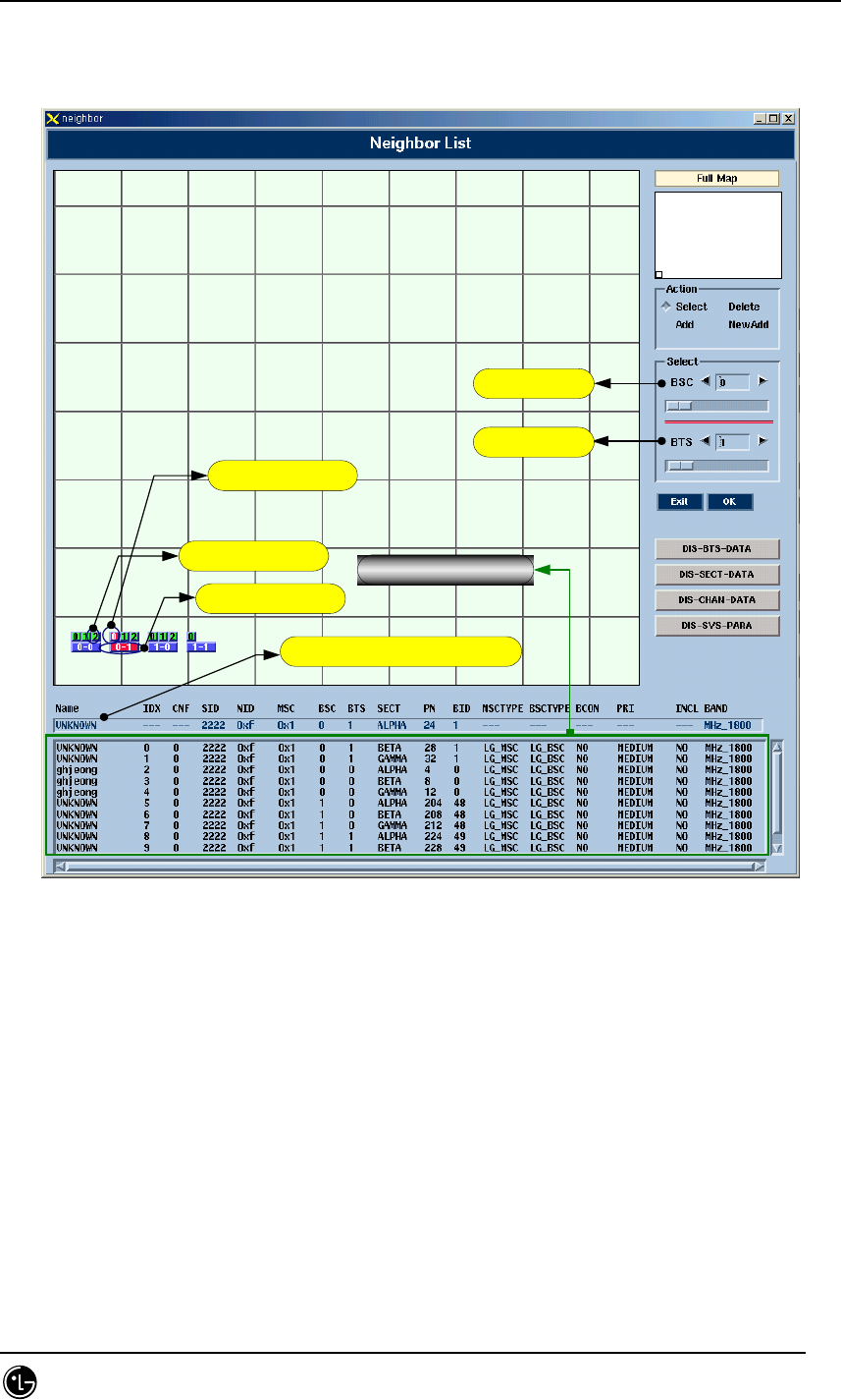
4.9.7. Neighbor Control Window (neighbor)
4.9.7.1. Overview.
Graphic neighbor is a tool that helps addition and deletion of the information related to
the BTS neighbor. User can view, add and delete the information related to neighbor
using the existing MMC but it requires the user to input lots of data. Therefore,
graphic neighbor minimize the input amount of user for user’s convenience.
4.9.7.2. Environment Setup.
Refer to the environment setup of stmGUI.
4.9.7.3. Directions for Use
Most of the directions are constituted of drawings and refer to the CDMX for detailed
operation.
Press neighbor among the buttons of Manager to start.
Fig. 4.9-36 Neighbor Start Icon
The following initial screen appears.
STAREX-IS BSM Manual
Page:577(877)
Issue:1.
0
SMD-011-PMA210
Fig. 4.9-36 Neighbor Initial Screen
STAREX-IS BSM Manual
Page:578(877)
Issue:1.
0
SMD-011-PMA210
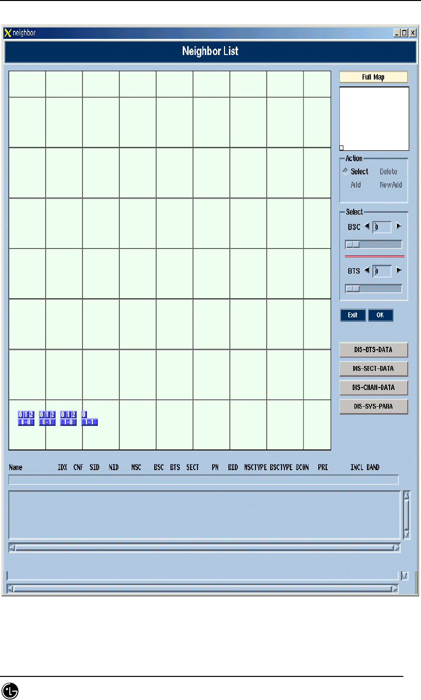
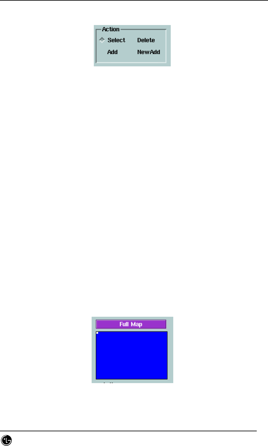
4.9.7.3.1. Main Menu
Fig. 4.9-37 Main Menu Screen
User can select a function in this screen.
Select : select or change the BTS or sector. For selection, select a BTS first and
then select a sector in the BTS.
Delete : delete the neighbor in the presently selected sector. Press sector to be
deleted after selection.
Add : add neighbor into the presently selected sector. Press a sector to be added
after selection.
NewAdd : add a neighbor of other MSC into the presently selected sector. Input
information into the window field appeared after selection.
(There is no default value)
4.9.7.3.2. BTS Selection
There are two methods for selecting BTS.
Surely, the BTS subjected to the MSC of the presently operating system can be
selected.
4.9.7.3.2.1. Method using Map.
Fig. 4.9-38 Full Map
Dragging mouse can search the desired location here. Click BTS (label : x-y ) in the

STAREX-IS BSM Manual
Page:579(877)
Issue:1.
0
SMD-011-PMA210
desired location with this method and press the sector of the BTS to select.
4.9.7.3.2.2. Selection Method by BTS ID.
Fig. 4.9-39 Random BTS Selection
BSC : It is the BSC to which the BTS belongs.
BTS : It is the BTS ID of the BTS.
Press OK button to complete the selection.
4.9.7.3.2.3. Selection Example.
Fig.4.9-40 Initial Screen (Before selecting BTS )
Fig. 4.9-41 After selecting BTS.
Fig. 4.9-42 After selecting Sector(Green: neighbor).
STAREX-IS BSM Manual
Page:580(877)
Issue:1.
0
SMD-011-PMA210
4.9.7.3.3. Neighbor Information
Fig. 4.9-43 Neighbor Information Screen
The own neighbor list checking is possible through the information in the lower part or
the green tinted sector.
Selected Sector
Neighbor
Selected BSC,BTS
BSC ID
BTS ID
Selected Sector Information
Neighbor Information

STAREX-IS BSM Manual
Page:581(877)
Issue:1.
0
SMD-011-PMA210
4.9.7.3.4. Neighbor Addition
The following window appears after selecting neighbor to be added.
Fig. 4.9-44 Inputting neighbor belongs to mother MSC
Adding neighbor belongs to the mother MSC requires the user to input just 4~6 fields.
Fig. 4.9-45 Inputting neighbor belongs to other MSC
STAREX-IS BSM Manual
Page:582(877)
Issue:1.
0
SMD-011-PMA210
Adding neighbor belongs to other MSC requires the user to input all the information.
Fig. 4.9-46 Default Value upon Input
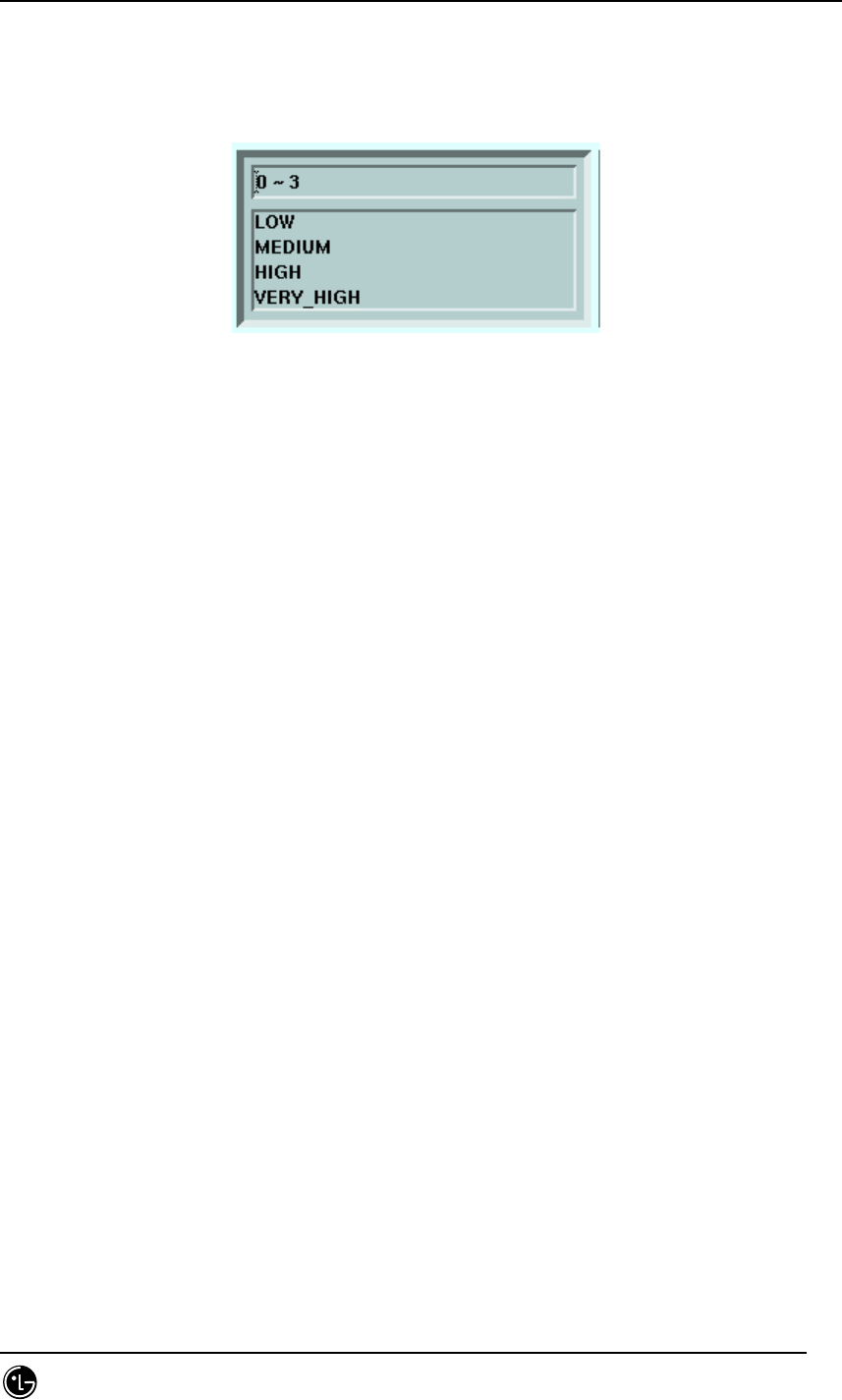
Select a field to be input then the system shows the default values. To select a value
input the value onto the corresponding input space or select one among the values in
the lower part with mouse. Press OK after the input is done or press Cancel to return
to the Main screen.
4.9.7.3.5. Neighbor Deletion
Deletion can be completed with two kinds of method.
Press the corresponding line in the lower part or press the BTS sector button.
4.9.7.4. Suggestions in Operation
4.9.7.4.1. The order of priority
Graphic Neighbor is a tool for adding/deleting neighbors. Therefore, performing
extension or deletion with MMC can bring out a wrong result while the Graphic
Neighbor is being used. And if it is performed the user should run the Graphic
Neighbor once again. The neighbor intercommunicates with the configuration block
(CDMX) through MMI block. Consequently, the two blocks should be in normal
operation.
STAREX-IS BSM Manual
Page:583(877)
Issue:1.
0
SMD-011-PMA210
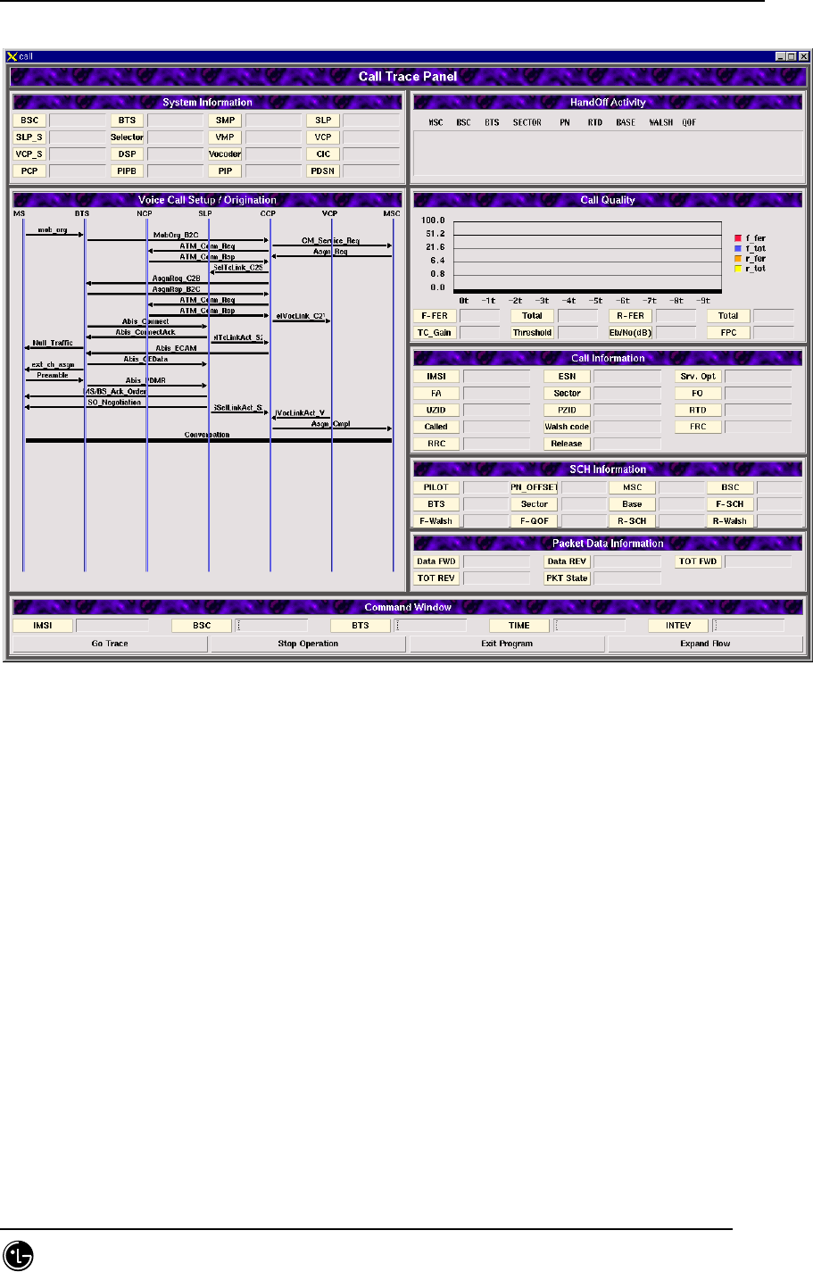
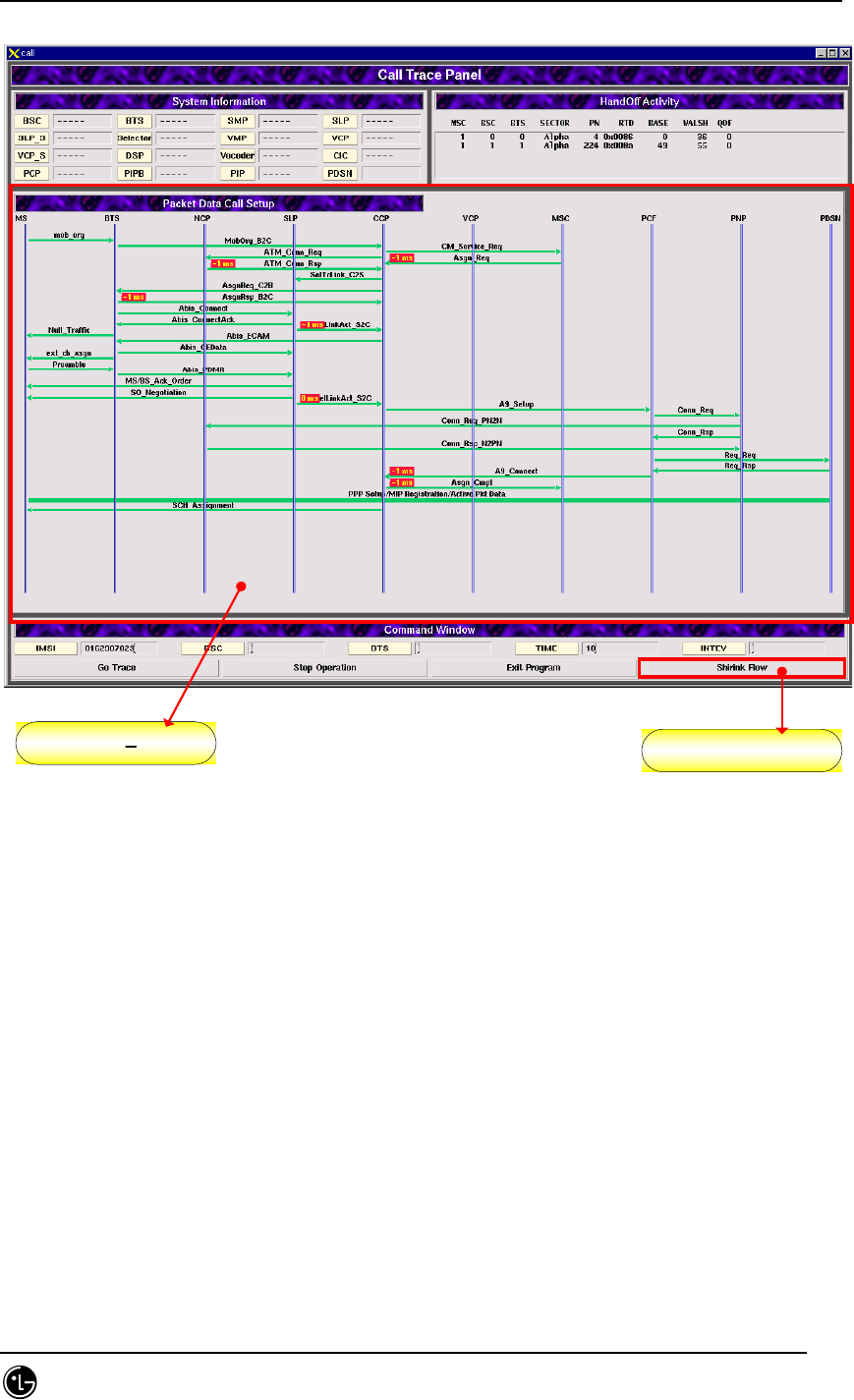
4.9.8. Call Trace Window
4.9.8.1. Overview.
Call Trace Window is a tool that shows all kinds of call trace information for a specific
for a specific MS onto the GUI (Graphic User Interface) screen of the user’s terminal.
Call trace command can be executed and the results can be checked through the
existing MMC or dedicated window for call trace. The user can set time as long as he
want with Timer for the maximum of two MS to trace calls.
4.9.8.2. Environment Setup
Refer to the environment setup of stmGUI
.
4.9.8.3. Directions for Use.
Most of the directions are constituted of drawings and refer to the TSMX Block for
detailed operation.
Press call among the buttons of Manager to start.
Fig. 4.9-47 Call Trace Start Icon
Then the following screen appears.
STAREX-IS BSM Manual
Page:584(877)
Issue:1.
0
SMD-011-PMA210
Fig. 4.9-48 Call Trace Initial Screen
STAREX-IS BSM Manual
Page:585(877)
Issue:1.
0
SMD-011-PMA210
4.9.8.3.1. Sub Menu.
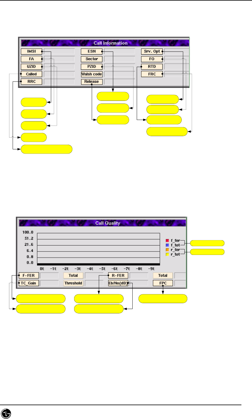
단말번호
CDMA CH
User Zone ID
착신측번호
Reverse Radio Config
단말 고유 넘버
Packet Zone Id
Release Reason
Service option
Frame Offset
Round Trip Delay
Forward Radio
Configuration
Fig. 4.9-49 Call Information.
Forward Frame Error Rate
Traffic Channel Gain
Reverse Frame Error Rate
신호대 잡음비
Forward Power Control
Forwad side
Reverse side
Fig. 4.9-50 Call Quality
STAREX-IS BSM Manual
Page:586(877)
Issue:1.
0
SMD-011-PMA210
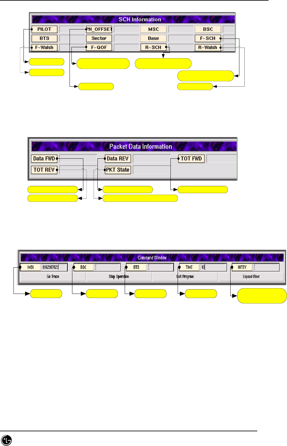
기지국 정보
Forward Walsh
Forward Quais Orgonal
Function
Reverse Supplement
CHannel
Forward Supplement
CHannel
Reverse Walsh섹터 정보
Fig. 4.9-51 SCH Information
Forward data rate
Total Reverse data rate
Reverse data rate Total Forward data rate
Packet State (Dormant or Active)
Fig. 4.9-52 Packet Data Information
단말번호 BSC ID BTS ID Trace Time FER Report
Interval Time
Fig. 4.9-53 Command Window
STAREX-IS BSM Manual
Page:587(877)
Issue:1.
0
SMD-011-PMA210
Input MS number (IMSI), BSC ID, BTS ID, Trace Time and FER Report Interval Time
into the command window of [Fig. 4.8-53], and press Go Trace button below, then the
call trace starts. Press Stop Operation beside Go Trace button to stop the process
during the operation and press Exit Program to end call trace program. The Expand
Flow shows the flow to the PDSN upon clicking it.
Click
!!
2개로 분할된 window
Fig. 4.9-54 Example of Expand Flow Button
If the user wants to see the expand flow hidden by the window at the right side after
call test, click Expand Flow button to see the expand flow.
STAREX-IS BSM Manual
Page:588(877)
Issue:1.
0
SMD-011-PMA210
Click
!!
하나로 통합된 window
Fig. 4.9-55 Example of Shrink Flow Button
To see the hidden window (Call Information, Call Quality, Handoff Activity at the right)
click Shrink Flow button.
STAREX-IS BSM Manual
Page:589(877)
Issue:1.
0
SMD-011-PMA210
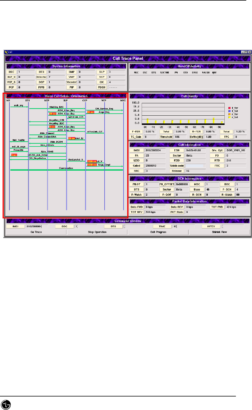
4.9.8.3.2. Voice Call
4.9.8.3.2.1. Origination Call (Voice Call Setup / Origination)
-----
Fig. 4.9-56 Voice Call Setup / Origination
It is FLOW that shows voice originating call process procedure and System Information,
Call Information and Call Quality Information are represented on it. The handoff
information is also represented when the handoff is generated.
STAREX-IS BSM Manual
Page:590(877)
Issue:1.
0
SMD-011-PMA210
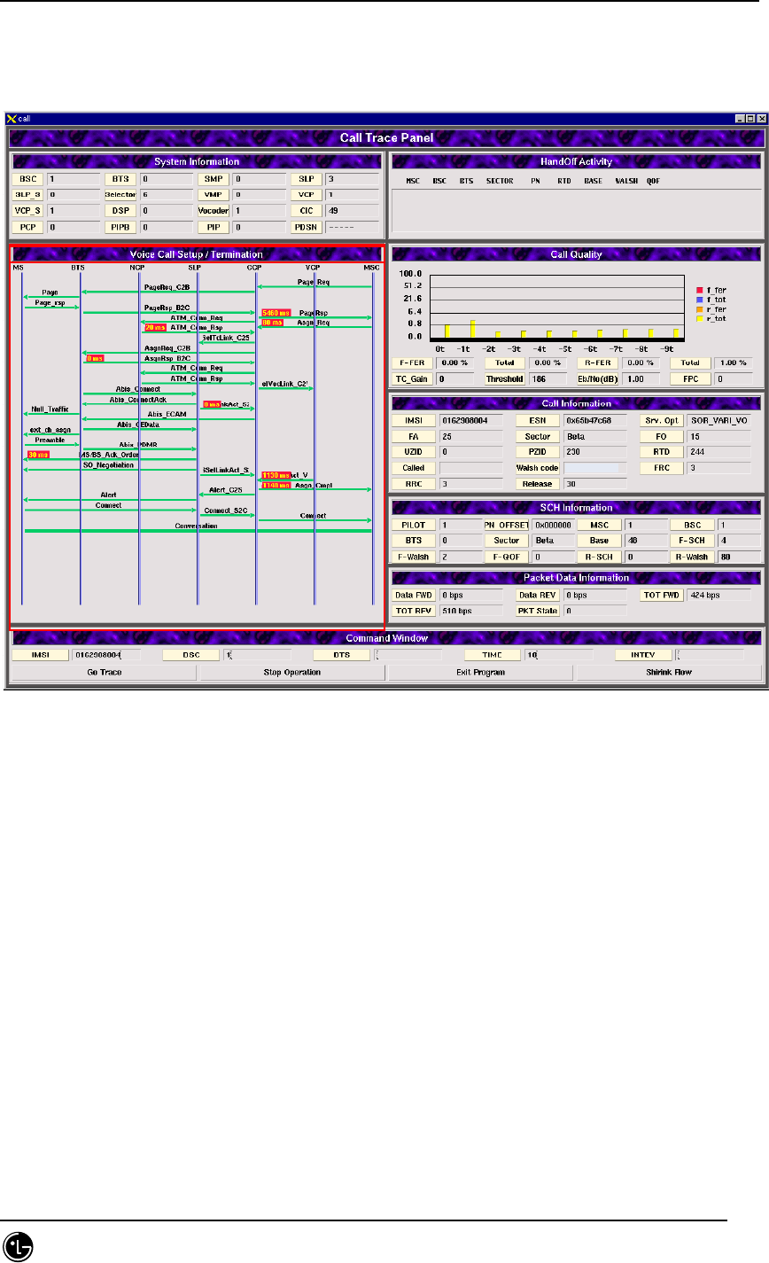
4.9.8.3.2.2. Termination Call.( Voice Call Setup / Termination)
-----
Fig. 4.9-57 Voice Call Setup / Termination
It is FLOW that shows the voice originating call process procedure, and System
Information, Call Information and Call Quality Information are represented on it. The
handoff information is also represented when the handoff is generated.
STAREX-IS BSM Manual
Page:591(877)
Issue:1.
0
SMD-011-PMA210
4.9.8.3.3. Data Call
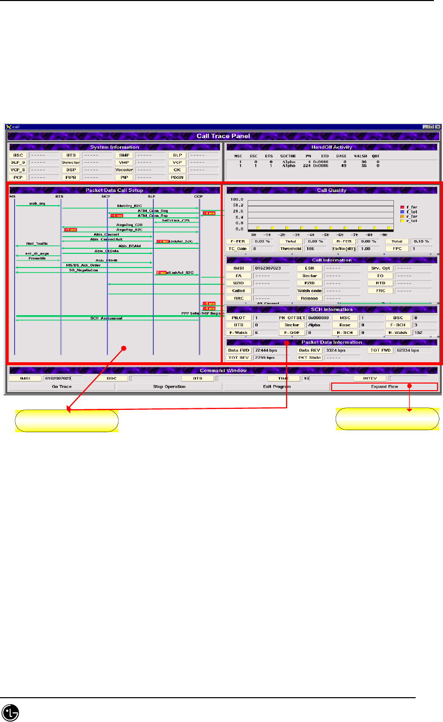
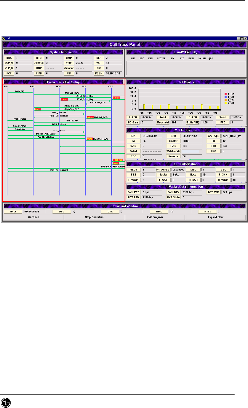
4.9.8.3.3.1. Packet Data Call Setup
-----
Fig 4.9-58 Packet Data Call Setup
It is FLOW that shows packet data call processing procedure and the System Information, Call
Information, Call Quality, Supplemental Channel Information and Packet Data Information are
represented on it. The handoff information is also represented on it when the handoff is
generated.
STAREX-IS BSM Manual
Page:592(877)
Issue:1.
0
SMD-011-PMA210
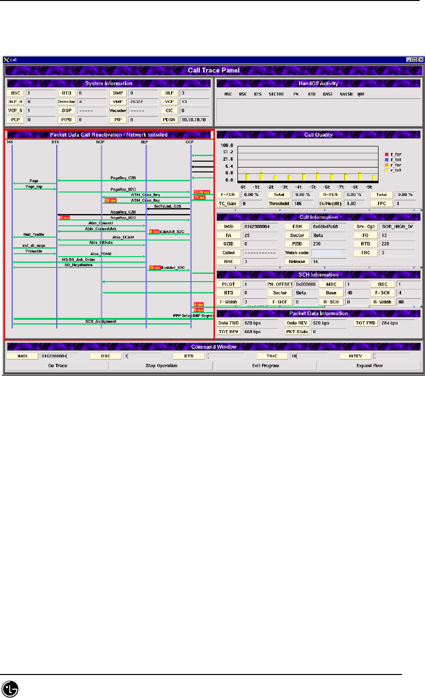
4.9.8.3.3.2. Packet Data Call Reactivation / Network Initiated
-----
Fig. 4.9-59 Packet Data Call Reactivation / Network Initiated
It is FLOW that shows processing procedure of the packet data call which fell into the
dormant status and then be reactivated by the network side. The System Information,
Call Information, Call Quality, Supplemental Channel Information and Packet Data
Information are represented. The handoff information is also represented on it when
the handoff is generated.
STAREX-IS BSM Manual
Page:593(877)
Issue:1.
0
SMD-011-PMA210
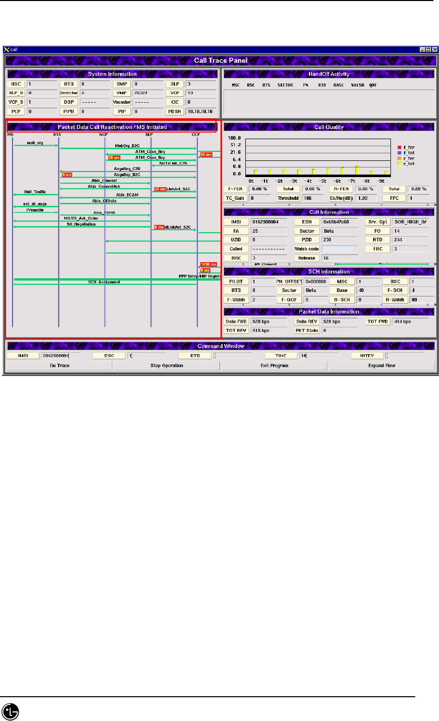
4.9.8.3.3.3. Packet Data Call Reactivation / MS Initiated
-----
Fig. 4.9-60 Packet Data Call Reactivation / MS Initiated
It is FLOW that shows the process procedure of packet data call which fell into the
dormant status and then reactivated by the MS; the System Information, Call
Information, Call Quality, Supplemental Channel Information and Packet Data
Information are represented on it. The handoff information is also represented on it
when the handoff is generated.

STAREX-IS BSM Manual
Page:594(877)
Issue:1.
0
SMD-011-PMA210
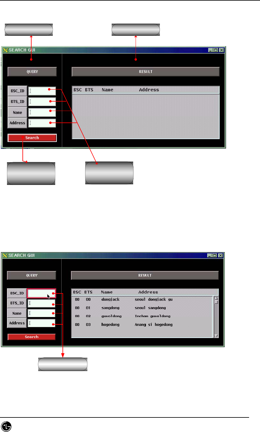
4.9.9. BTS Address Search Window.
4.9.9.1. Overview.
The BTS address search program provides the following functions: 1) it can search the
corresponding BTS name and address with BSC and BTS number. 2) it can search BSC
and BTS number and address with BTS name. 3) it can search BSC and BTS number
and name with BTS address.
4.9.9.2. Environment Setup.
It use Solaris 2.7 and Informix 7.3.1 as OS.
4.9.9.2.1. Data Files
bts_name.info : the file contains BTS name and address
4.9.9.3. Directions for Use.
The initial condition is scheduled to configure in the future.
STAREX-IS BSM Manual
Page:595(877)
Issue:1.
0
SMD-011-PMA210
질의 window. Result window.
Search Button
BSC,BTS ID로
검색시 사용
검색하기 위한
입력필드
Fig. 4.9-61 BTS Address Search Window Initial Screen
4.9.9.3.1. File Information Display
Enter !!
Fig. 4.9-62 File Information Display
STAREX-IS BSM Manual
Page:596(877)
Issue:1.
0
SMD-011-PMA210
Press Enter key on any place of the input field to display the file information on the
result window.
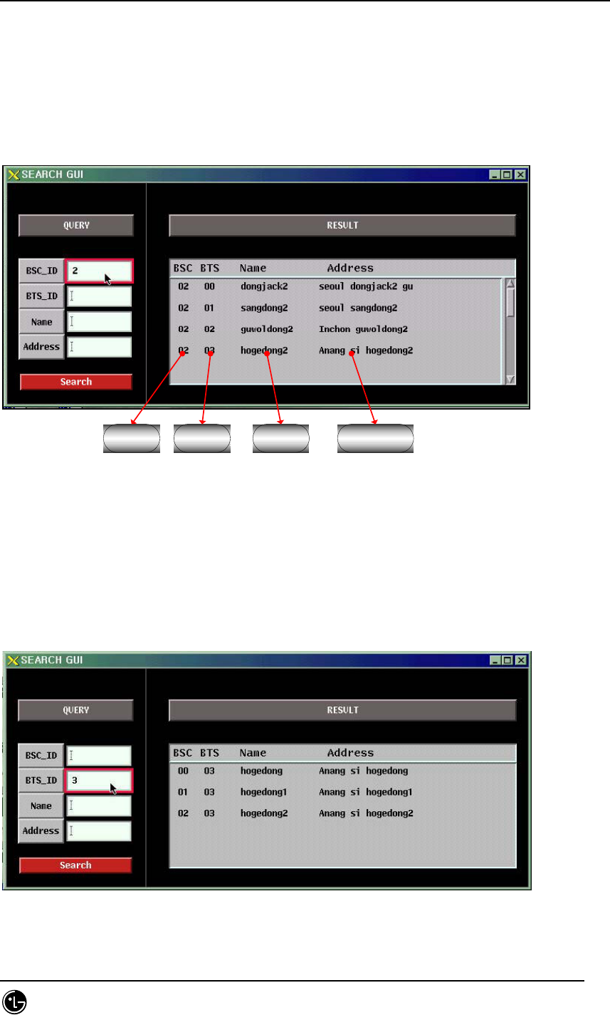
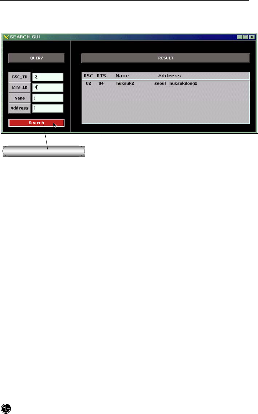
4.9.9.3.2. Searching with BSC ID.
BSC ID BTS ID 기지국이름 기지국 주소
Fig. 4.9-63 Searching with BSC
Input desired BSC number and press Enter key to display the result on the result
window when searching with BSC_ID.
4.9.9.3.3. Searching by BTS ID.
Fig. 4.9-64 Searching by BTS
STAREX-IS BSM Manual
Page:597(877)
Issue:1.
0
SMD-011-PMA210
Input desired BTS number and press Enter key to display the result on the result
window when searching with BTS_ID.
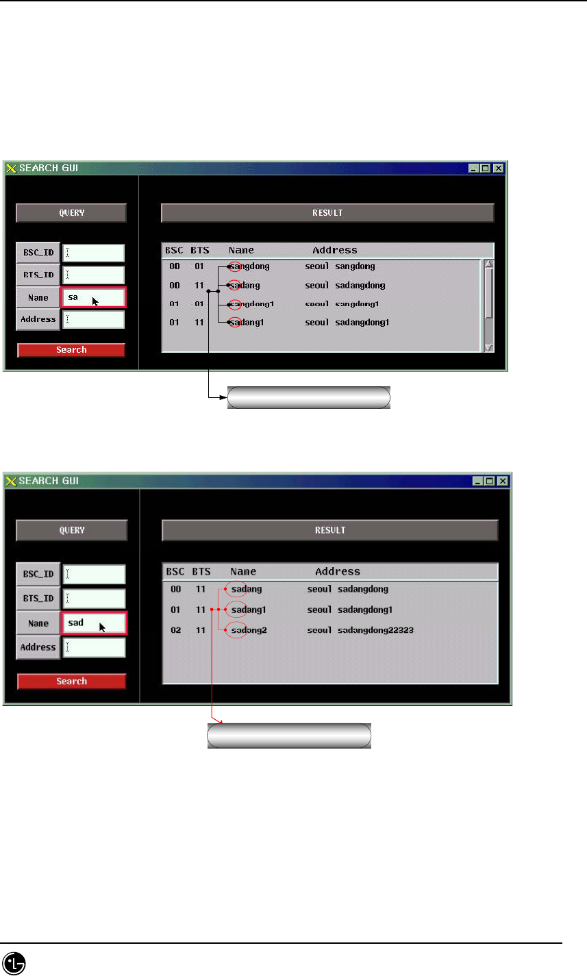
4.9.9.3.4. Searching with BTS name.
접두어(Prefix)검색.
Fig. 4.9-65 Searching with BTS name-1
접두어(Prefix)검색.
Fig. 4.9-66 Searching with BTS name-2
If the user input name into the name input field when searching with BTS name, the
searching is performed with real-time prefix. For example, the names start with “s”
are displayed upon inputting “s”, the names start with “sad” are displayed upon
inputting “sad”.
STAREX-IS BSM Manual
Page:598(877)
Issue:1.
0
SMD-011-PMA210
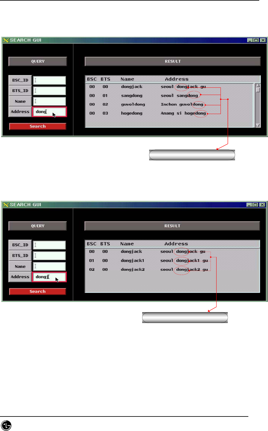
4.9.9.3.5. Searching with BTS address.
단어로 검색.
Fig. 4.9-67 Searching with BTS Address-1
단어로 검색.
Fig. 4.9-68 Searching with BTS Address-2
The BTS addresses are searched with real-time words upon inputting address into the
address input field when searching with BTS address. For example, the addresses
start with “dong” are displayed upon inputting “dong”, and the addresses start with

STAREX-IS BSM Manual
Page:599(877)
Issue:1.
0
SMD-011-PMA210
“dongj” are displayed upon inputting “dongj”.
STAREX-IS BSM Manual
Page:600(877)
Issue:1.
0
SMD-011-PMA210
4.9.9.3.6. Searching with Search Button.
Search Button Click !
Fig. 4.9-69 Searching with Search Button.
Search Button provides the following functions: 1) simultaneous searching for BSC_ID
and BTS_ID 2) single searching for BSC_ID or BTS_ID
4.9.9.4. Suggestions for Operation.
4.9.9.4.1. The Order of Priority.
BTS address searching program is a graphic tool that provides the following function:
1) searching BTS name and address with BSC ID and BTS ID, 2) searching BSC ID,
BTS ID, and address with name, 3) searching BSC ID, BTS ID, and name with address.
The address search program should be rerun when inserting, deleting or modifying the
data of the bts_name.info file that includes BTS information.
The Informix should be normally run because the Informix db is used for searching.
STAREX-IS BSM Manual
Page:601(877)
Issue:1.
0
SMD-011-PMA210
5. BSM On-Line Message
5.1. Fault/Alarm Message
5.1.1. Alarm Message
5.1.1.1. CAN Occurrence Alarm Message
5.1.1.1.1. CAMB
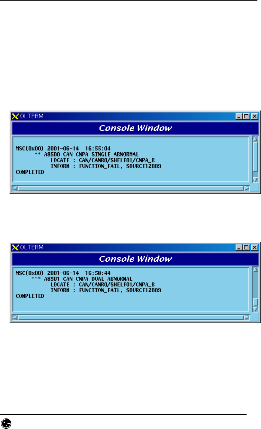
5.1.1.1.1.1. CNP Processor
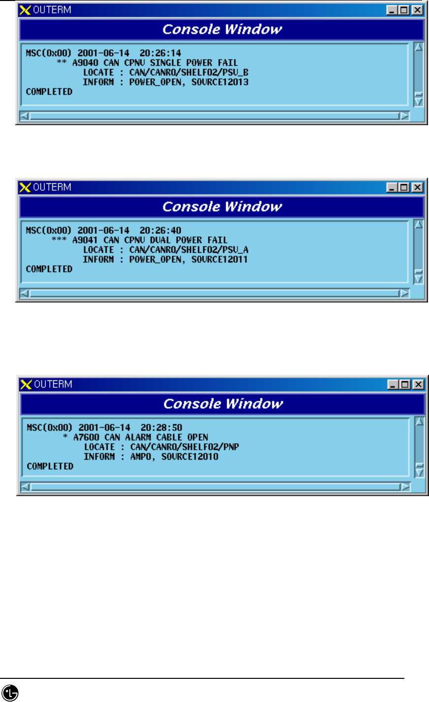
1) When A-Side of the duplicated CNP is normal and functional problems occur on
the B- side board
Fig. 5.1-1 CNP Single Function Fail
2) When functional problems occur on the B-Side after functional problems occur
on the A-Side of the duplicated CNP,
Fig. 5.1-2 CNP Dual Function Fail
3) When A-Side of the duplicated CNP is normal and the B-Side board is removed
STAREX-IS BSM Manual
Page:602(877)
Issue:1.
0
SMD-011-PMA210
Fig. 5.1-3 CNP Single Board Open Fail
4) When B-Side is removed after A-Side of the duplicated CNP is removed
Fig. 5.1-4 CNP Dual Board Open Fail
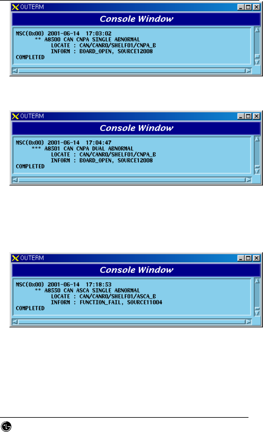
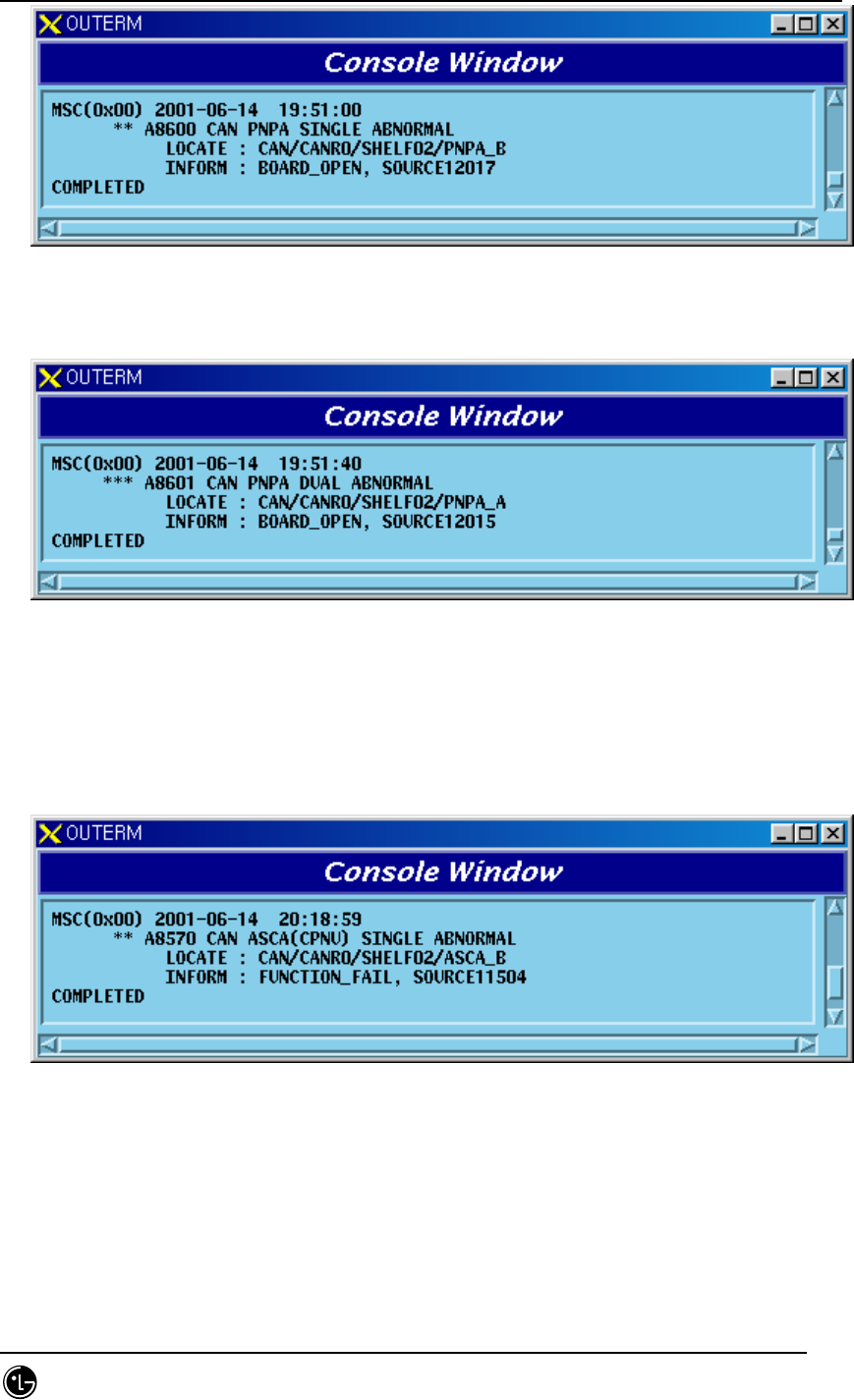
5.1.1.1.1.2. ASCA Board
1) When A-Side of the duplicated ASCA is normal and functional problems occur
on the B-Side board
Fig. 5.1-5 CAN ASCA Single Function Fail
2) When functional problems occur on the B-Side after functional problems occur
on the A-Side of the duplicated ASCA

STAREX-IS BSM Manual
Page:603(877)
Issue:1.
0
SMD-011-PMA210
Fig. 5.1-6 CAN ASCA Dual Function Fail
3) When A-Side of the duplicated ASCA is normal and B-Side board is removed
Fig. 5.1-7 CAN ASCA Single Board Open Fail
4) When B-Side is removed after A-Side of the duplicated ASCA is removed
Fig. 5.1-8 CAN ASCA Dual Open Fail
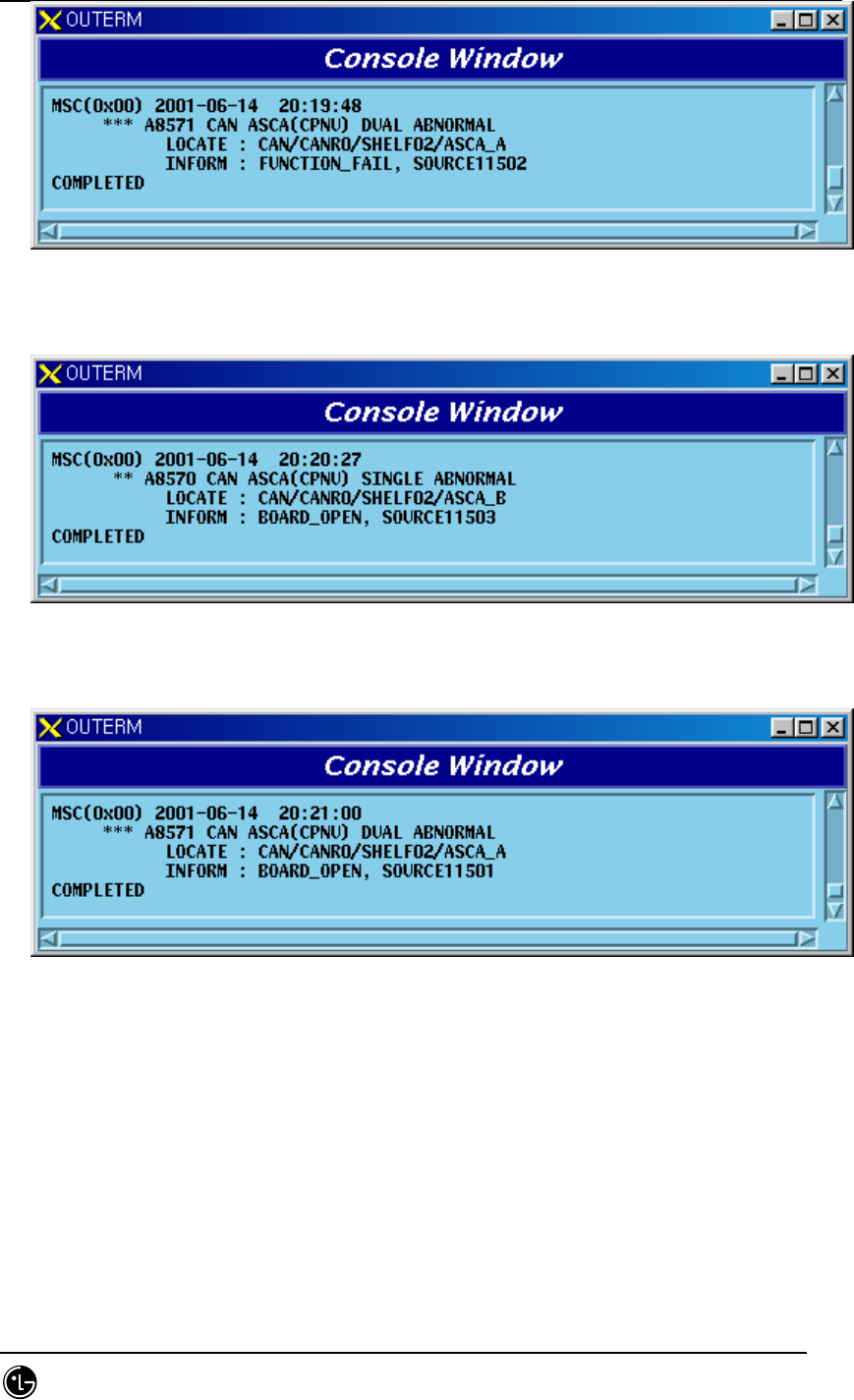
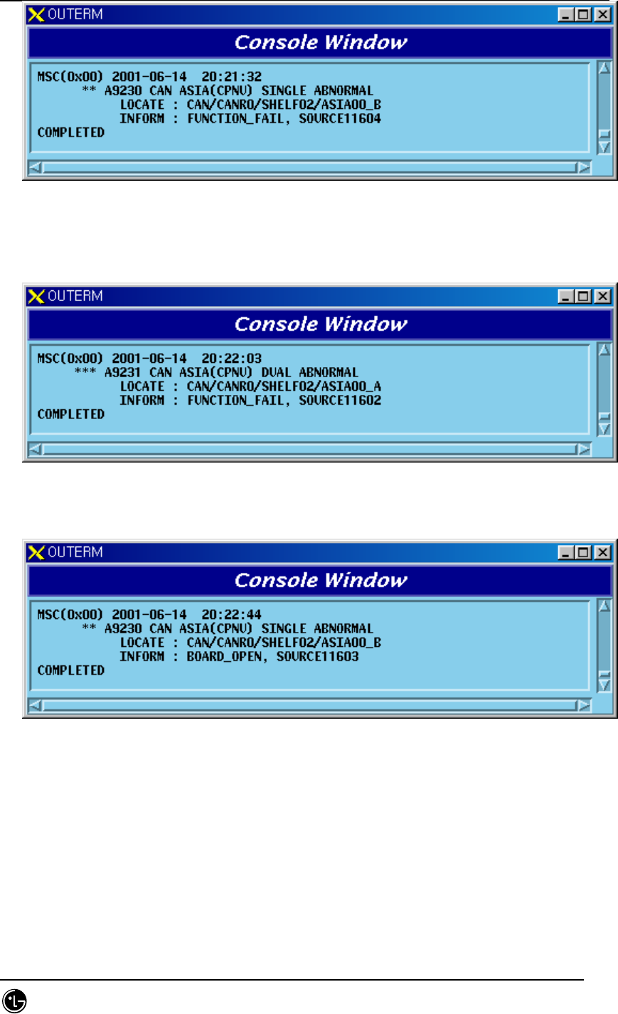
5.1.1.1.1.3. ASIA Board
1) When A-Side of the duplicated ASIA is normal and functional problems occur on
the B-Side board

STAREX-IS BSM Manual
Page:604(877)
Issue:1.
0
SMD-011-PMA210
Fig. 5.1-9 CAN ASIA Single Function Fail
2) When functional problems occur on the B-Side board after functional problems
occur on the A-Side of the duplicated ASIA
Fig. 5.1-10 CAN ASIA Dual Function Fail
3) When A-Side of the duplicated ASIA is normal and B-Side board is removed
Fig. 5.1-11 CAN ASIA Single Board Open Fail
4) When B-Side board is removed after A-Side of the duplicated ASIA is removed
STAREX-IS BSM Manual
Page:605(877)
Issue:1.
0
SMD-011-PMA210
Fig. 5.1-12 CAN ASIA Single Board Open Fail
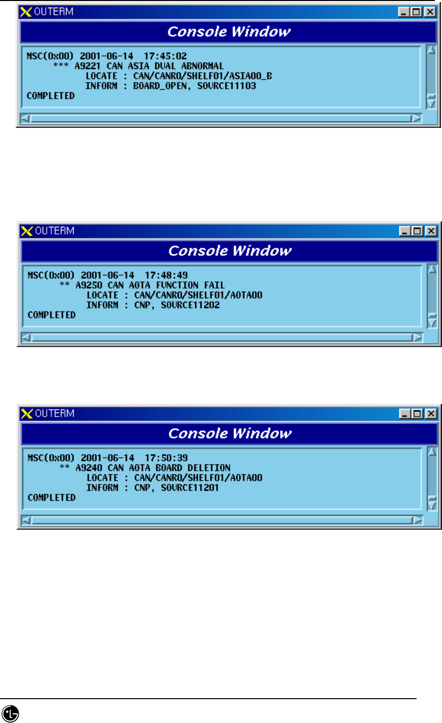
5.1.1.1.1.4. AOTA Board
1) When functional faults occur on AOTA board
Fig. 5.1-13 CAN AOTA Function Fail
2) When AOTA board is removed
Fig. 5.1-14 CAN AOTA Board Open Fail
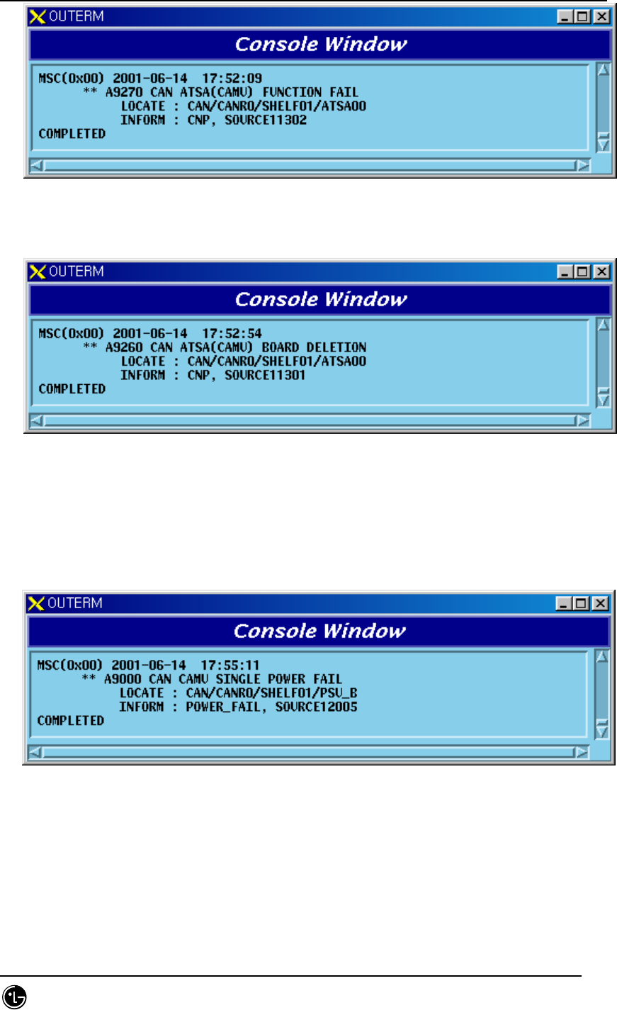
5.1.1.1.1.5. ATSA Board
1) When functional faults occur on ATSA board
STAREX-IS BSM Manual
Page:606(877)
Issue:1.
0
SMD-011-PMA210
Fig. 5.1-15 CAN ATSA Function Fail
2) When ATSA board is removed
Fig. 5.1-16 CAN ATSA Board Open Fail
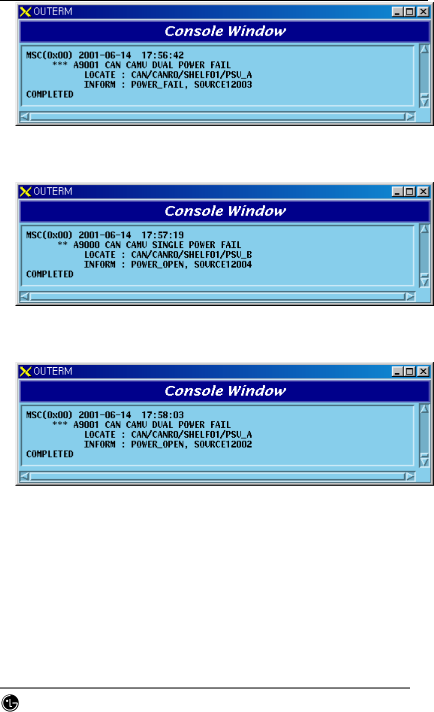
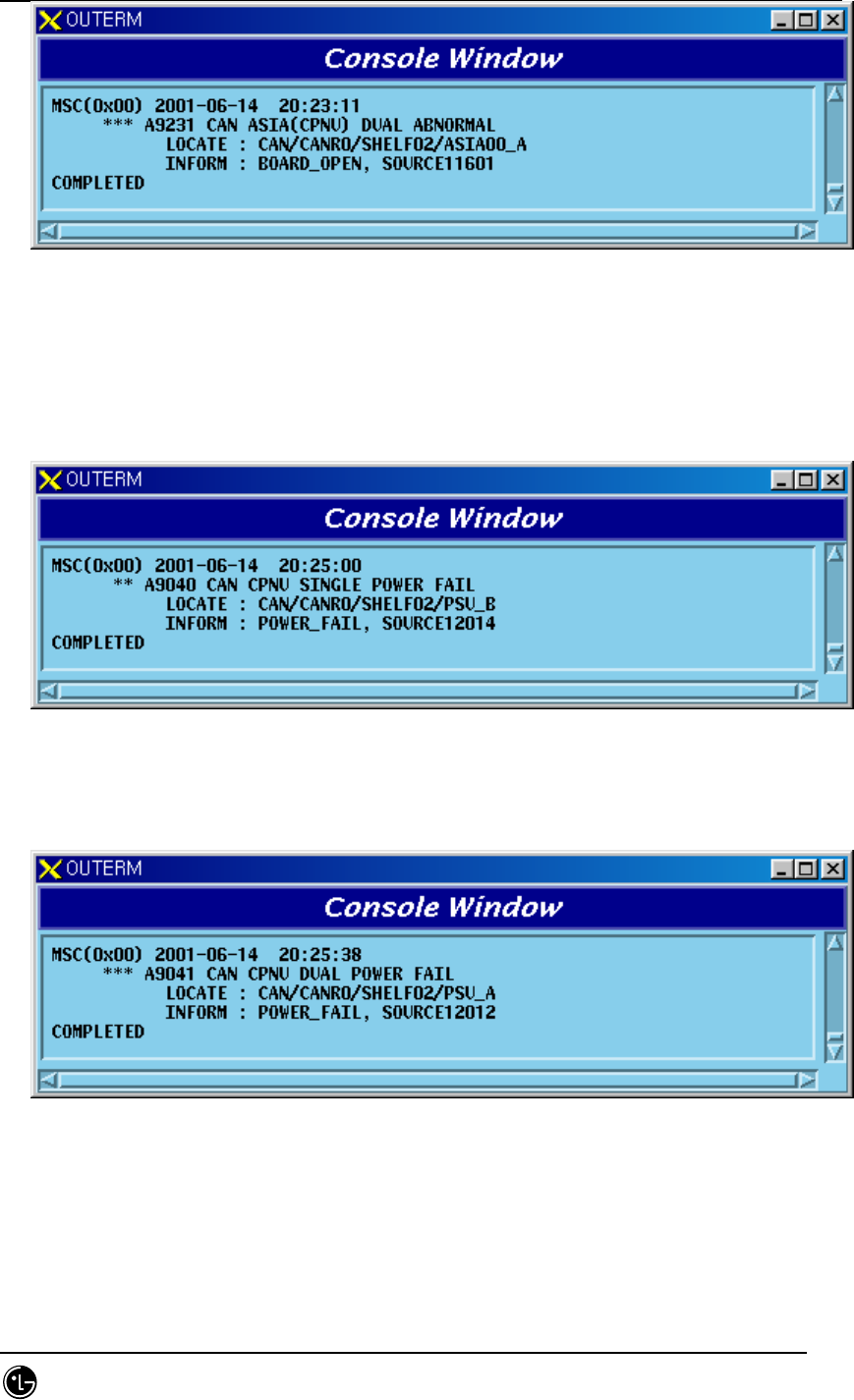
5.1.1.1.1.6. PRI Board
1) When A-Side of the duplicated PRI is normal and functional problems occur on
the B-Side board
Fig. 5.1-17 CAMB PRI Single Power Fail
2) When functional problems occur on the A-Side after functional problems occur
on the B-Side of the duplicated PRI
STAREX-IS BSM Manual
Page:607(877)
Issue:1.
0
SMD-011-PMA210
Fig. 5.1-18 CAMB PRI Dual Power Fail
3) When A-Side of the duplicated PRI is normal and B-Side board is removed
Fig. 5.1-19 CAMB PRI Single Power Open Fail
4) When A-Side is removed after B-Side of the duplicated PRI is removed
Fig. 5.1-20 CAMB PRI Dual Power Open Fail
5.1.1.1.1.7. Others
1) When CAMB Alarm Cable is removed

STAREX-IS BSM Manual
Page:608(877)
Issue:1.
0
SMD-011-PMA210
Fig. 5.1-21 CAN Alarm Cable Open
5.1.1.1.2. CPNB
5.1.1.1.2.1. PNP Processor
1) When A-Side of the duplicated PNP is normal and functional problems occur on
the B-Side board
Fig. 5.1-22 CAN PNP Single Function Fail
2) When functional problems occur on the A-Side after B-Side of the duplicated
PNP has a functional problem
Fig. 5.1-23 CAN PNP Dual Function Fail
3) When A-Side of the duplicated PNP is normal and B-Side board is removed
STAREX-IS BSM Manual
Page:609(877)
Issue:1.
0
SMD-011-PMA210
Fig. 5.1-24 CAN PNP Single Board Open Fail
4) When A-Side is removed after B-Side of the duplicated PNP is removed
Fig. 5.1-25 CAN PNP Dual Board Open Fail
5.1.1.1.2.2. ASCA Board
1) When A-Side of the duplicated ASCA is normal and functional problems occur
on the B-Side board
Fig. 5.1-26 CPNB ASCA Single Function Fail
2) When functional problems occur on the A-Side after B-Side of the duplicated
ASCA has a functional problem
STAREX-IS BSM Manual
Page:610(877)
Issue:1.
0
SMD-011-PMA210
Fig. 5.1-27 CPNB ASCA Dual Function Fail
3) When A-Side of the duplicated ASCA is normal and B-Side board is removed
Fig. 5.1-28 CPNB ASCA Single Board Open Fail
4) When A-Side is removed after B-Side of the duplicated ASCA is removed
Fig. 5.1-29 CPNB ASCA Dual Board Open Fail
5.1.1.1.2.3. ASIA Board
1) When A-Side of the duplicated ASIA is normal and functional problems occur on
the B-Side board
STAREX-IS BSM Manual
Page:611(877)
Issue:1.
0
SMD-011-PMA210
Fig. 5.1-30 CPNB ASIA Single Function Fail
2) When functional problems occur on the A-Side after B-Side of the duplicated
ASIA has a functional problem
Fig. 5.1-31 CPNB ASIA Dual Function Fail
3) When A-Side of the duplicated ASIA is normal and B-Side board is removed
Fig. 5.1-32 CPNB ASIA Single Board Open Fail
4) When A-Side is removed after B-Side of the duplicated ASIA is removed
STAREX-IS BSM Manual
Page:612(877)
Issue:1.
0
SMD-011-PMA210
Fig. 5.1-33 CPNB ASIA Dual Board Open Fail
5.1.1.1.2.4. PRI Board
1) When A-Side of the duplicated PRI is normal and functional problems occur on
the B-Side board
Fig. 5.1-34 CPNB PRI Single Power Fail
2) When functional problems occur on the A-Side after B-Side of the duplicated
PRI has a functional problem
Fig. 5.1-35 CPNB PRI Dual Power Fail
3) When A-Side of the duplicated PRI is normal and B-Side board is removed
STAREX-IS BSM Manual
Page:613(877)
Issue:1.
0
SMD-011-PMA210
Fig. 5.1-36 CPNB PRI Single Power Open Fail
4) When A-Side is removed after B-Side of the duplicated PRI is removed
Fig. 5.1-37 CPNB PRI Dual Power Open Fail
5.1.1.1.2.5. Others
1) CPNB Alarm Cable is removed
Fig. 5.1-38 CPNB Alarm Cable Open
5.1.1.1.3. PCFB(PCP)
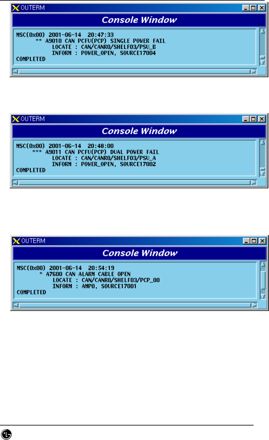
5.1.1.1.3.1. PCP Processor
1) When A-Side of the duplicated PCP is normal and functional problems occur on
the B-Side board

STAREX-IS BSM Manual
Page:614(877)
Issue:1.
0
SMD-011-PMA210
Fig. 5.1-39 PCFB PCP Single Function Fail
2) When functional problems occur on the A-Side after B-Side of the duplicated
PCP has a functional problem
Fig. 5.1-40 PCFB PCP Dual Function Fail
3) When A-Side of the duplicated PCP is normal and B-Side board is removed
Fig. 5.1-41 PCFB PCP Single Board Open Fail
4) When A-Side is removed after B-Side of the duplicated PCP is removed

STAREX-IS BSM Manual
Page:615(877)
Issue:1.
0
SMD-011-PMA210
Fig. 5.1-42 PCFB PCP Dual Board Open Fail
5.1.1.1.3.2. BCRA Board
1) When A-Side of the duplicated BCRA is normal and functional problems occur
on the B-Side board
Fig. 5.1-43 CPNB(PCP) BCRA Single Function Fail
2) When functional problems occur on the A-Side after B-Side of the duplicated
BCRA has a functional problem
Fig. 5.1-44 CPNB(PCP) BCRA Dual Function Fail
3) When A-Side of the duplicated BCRA is normal and B-Side board is removed

STAREX-IS BSM Manual
Page:616(877)
Issue:1.
0
SMD-011-PMA210
Fig. 5.1-45 CPNB(PCP) BCRA Single Board Open Fail
4) When A-Side is removed after B-Side of the duplicated BCRA is removed
Fig. 5.1-46 CPNB(PCP) BCRA Dual Board Open Fail
5.1.1.1.3.3. UCPA(PIP) Board
1) When functional faults occur on UCPA(PIP) board
Fig. 5.1-47 CPNB(PCP) PIP Function Fail
2) When UPCA(PIP) board is removed
STAREX-IS BSM Manual
Page:617(877)
Issue:1.
0
SMD-011-PMA210
Fig. 5.1-48 CPNB(PCP) PIP Board Open Fail
5.1.1.1.3.4. FERA Board
1) When A-Side of the duplicated FERA is normal and functional problems occur
on the B-Side board
Fig. 5.1-49 CPNB(PCP) FERA Single Function Fail
2) When functional problems occur on the A-Side after B-Side of the duplicated
FERA has a functional problem
Fig. 5.1-50 CPNB(PCP) FERA Dual Function Fail
3) When A-Side of the duplicated FERA is normal and B-Side board is removed
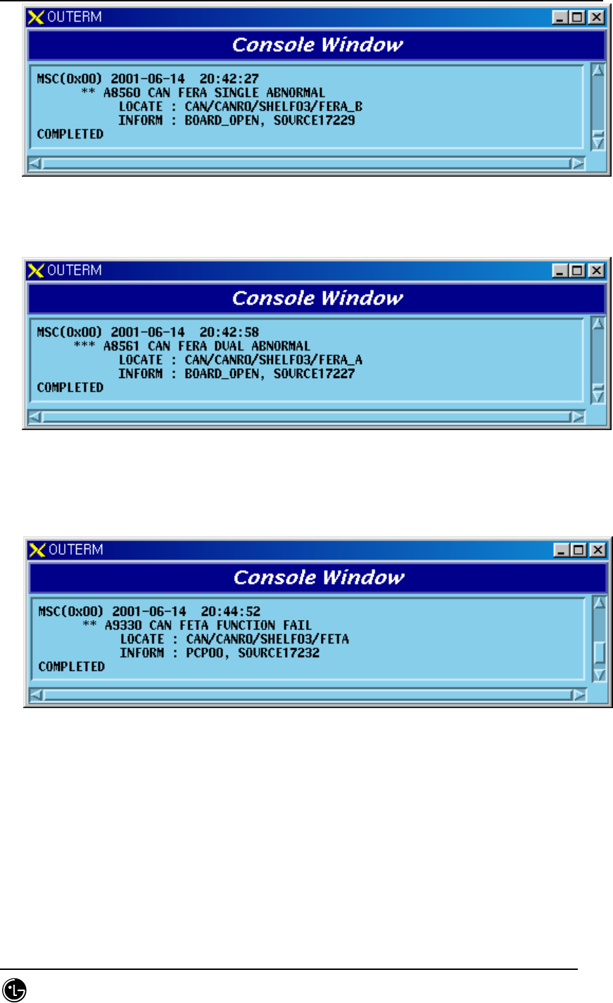
STAREX-IS BSM Manual
Page:618(877)
Issue:1.
0
SMD-011-PMA210
Fig. 5.1-51 CPNB(PCP) FERA Single Board Open Fail
4) When A-Side is removed after B-Side of the duplicated FERA is removed
Fig. 5.1-52 CPNB(PCP) FERA Dual Board Open Fail
5.1.1.1.3.5. FETA Board
1) When functional faults occur on FETA board
Fig. 5.1-53 CPNB(PCP) FETA Function Fail
2) When FETA board is removed

STAREX-IS BSM Manual
Page:619(877)
Issue:1.
0
SMD-011-PMA210
Fig. 5.1-54 CPNB(PCP) FETA Board Open Fail
5.1.1.1.3.6. PRI Board
1) When A-Side of the duplicated PRI is normal and functional problems occur on
the B-Side board
Fig. 5.1-55 CPNB(PCP) PRI Single Power Fail
2) When functional problems occur on the A-Side after B-Side of the duplicated
PRI has a functional problem
Fig. 5.1-56 CPNB(PCP) PRI Dual Power Fail
3) When A-Side of the duplicated PRI is normal and B-Side board is removed
STAREX-IS BSM Manual
Page:620(877)
Issue:1.
0
SMD-011-PMA210
Fig. 5.1-57 CPNB(PCP) PRI Single Power Open Fail
4) When A-Side is removed after B-Side of the duplicated PRI is removed
Fig. 5.1-58 CPNB(PCP) PRI Dual Power Open Fail
5.1.1.1.3.7. Others
1) When PCFU(PCP) Alarm Cable is removed
Fig. 5.1-59 CPNB(PCP) Alarm Cable Open
2) When faults occur in the link between FERA B-Side and FETA after the link
between FERA A-Side and FETA operates normally (maximum 3 links exist)
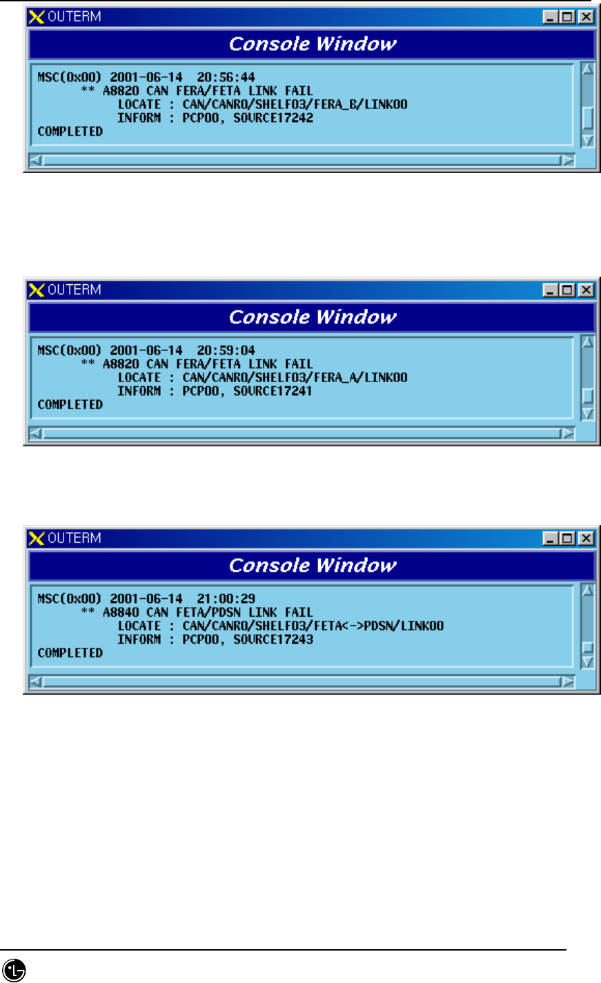
STAREX-IS BSM Manual
Page:621(877)
Issue:1.
0
SMD-011-PMA210
Fig. 5.1-60 LINK Fail between CPNB(PCP) FERA and FETA
3) When faults occur in the link between FERA A-Side and FETA after faults occur
in the link between FERA B-Side and FETA(maximum 3 links exist)
Fig. 5.1-61 LINK Fail between CPNB(PCP) FERA and FETA
4) When faults occur in the link between FETA and PDSN(maximum3 links exist)
Fig. 5.1-62 LINK Fail between CPNB(PCP) FETA and PDSN
5) When 1pps Clock is not provided for PCP normally
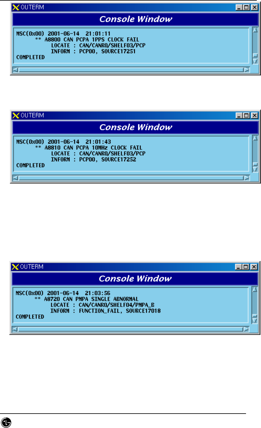
STAREX-IS BSM Manual
Page:622(877)
Issue:1.
0
SMD-011-PMA210
Fig. 5.1-63 PCFB PCP 1pps Clock Fail
6) When 10MHz Clock is not provided for PCP normally
Fig. 5.1-64 PCFB PCP 10MHz Clock Fail
5.1.1.1.4. PCFB(PMP)
5.1.1.1.4.1. PMP Processor
1) When A-Side of the duplicated PMP is normal and functional problems occur on
the B-Side board
Fig. 5.1-65 PCFB(PMP) PMP Single Function Fail
2) When functional problems occur on the A-Side after B-Side of the duplicated
PMP has a functional problem
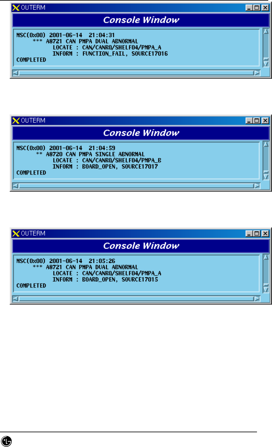
STAREX-IS BSM Manual
Page:623(877)
Issue:1.
0
SMD-011-PMA210
Fig. 5.1-66 PCFB(PMP) PMP Dual Function Fail
3) When A-Side of the duplicated PMP is normal and B-Side board is removed
Fig. 5.1-67 PCFB(PMP) PMP Single Board Open Fail
4) When A-Side is removed after B-Side board of the duplicated PMP is removed
Fig. 5.1-68 PCFB(PMP) PMP Dual Board Open Fail
5.1.1.1.4.2. BCRA Board
See BCRA of PCFU(PCP).
5.1.1.1.4.3. UCPA(PIP) Board
See UCPA(PIP) of PCFU(PCP).
5.1.1.1.4.4. FERA Board
See FERA of PCFU(PCP).
STAREX-IS BSM Manual
Page:624(877)
Issue:1.
0
SMD-011-PMA210
5.1.1.1.4.5. FETA Board
See FETA of PCFU(PCP).
5.1.1.1.4.6. PRI Board
See PRI of PCFU(PCP).
5.1.1.1.4.7. Others
See others of PCFU(PCP).
5.1.1.1.5. TGDB
5.1.1.1.5.1. GPSR Board
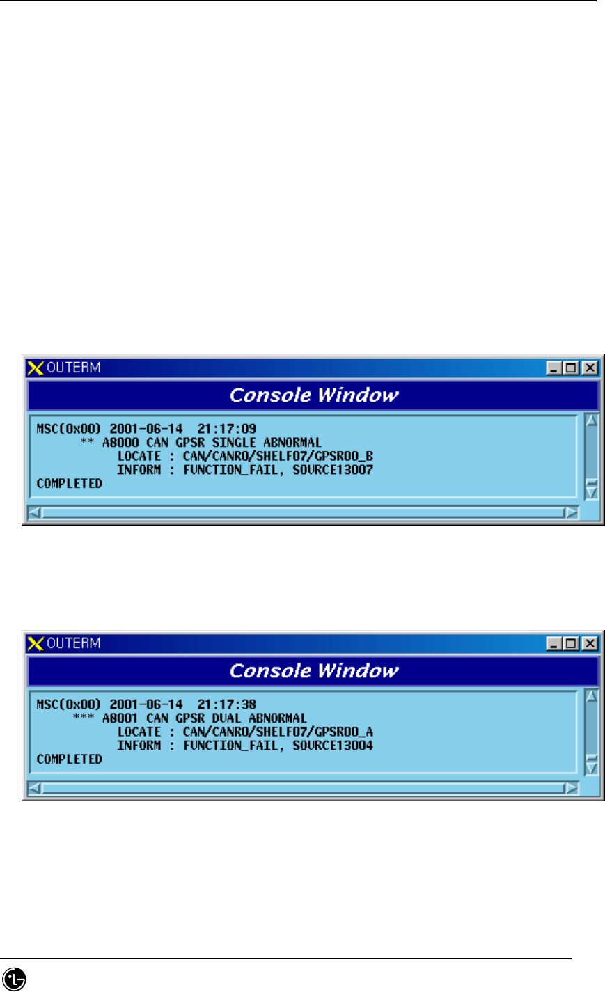
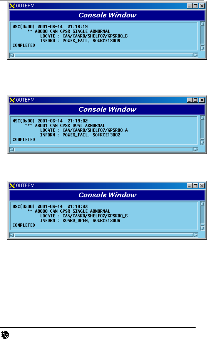
1) When A-Side of the duplicated GPSR is normal and functional problems occur
on the B-Side board
Fig. 5.1-69 TGDB GPSR Single Function Fail
2) When functional problems occur on the A-Side after B-Side of the duplicated
GPSR has a functional problem
Fig. 5.1-70 TGDB GPSR Dual Function Fail
3) When A-Side of the duplicated GPSR is normal and faults occur on the B-Side
power
STAREX-IS BSM Manual
Page:625(877)
Issue:1.
0
SMD-011-PMA210
Fig. 5.1-71 TGDB GPSR Single Power Fail
4) When a problem occurs on the A-Side power after B-Side power of the
duplicated GPSR has a problem
Fig. 5.1-72 TGDB GPSR Dual Power Fail
5) When A-Side of the duplicated GPSR is normal and B-Side board is removed
Fig. 5.1-73 TGDB GPSR Single Board Open Fail
6) When A-Side is removed after B-Side of the duplicated GPSR is removed
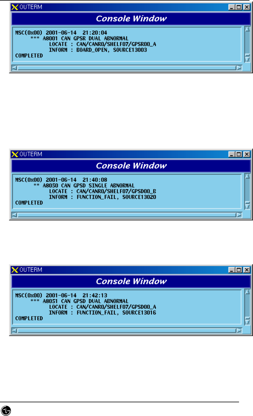
STAREX-IS BSM Manual
Page:626(877)
Issue:1.
0
SMD-011-PMA210
Fig. 5.1-74 TGDB GPSR Dual Board Open Fail
5.1.1.1.5.2. GPSD Board
1) When A-Side of the duplicated GPSD is normal and functional problems occur
on the B-Side board
Fig. 5.1-75 TGDB GPSD Single Function Fail
2) When functional problems occur on the A-Side after B-Side of the duplicated
GPSD has a functional problem
Fig. 5.1-76 TGDB GPSD Dual Function Fail
3) When A-Side of the duplicated GPSD is normal and faults occur on the B-Side
power
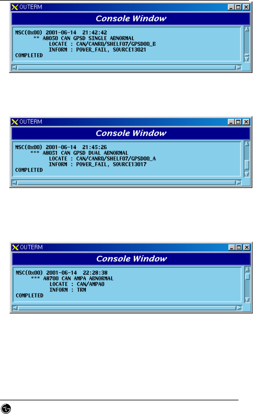
STAREX-IS BSM Manual
Page:627(877)
Issue:1.
0
SMD-011-PMA210
Fig. 5.1-77 TGDB GPSD Single Power Fail
4) When faults occur on the A-Side power after faults occur on the B-Side power
of the duplicated GPSD
Fig. 5.1-78 TGDB GPSD Dual Power Fail
5.1.1.1.5.3. AMP Processor
1) When faults occur in AMP Processor or a problem occurs in TCP/IP link
between BSM and AMP
Fig. 5.1-79 TGDB AMP Abnormal
5.1.1.1.5.4. Others
1) When a problem occurs in GPSR Alarm Cable
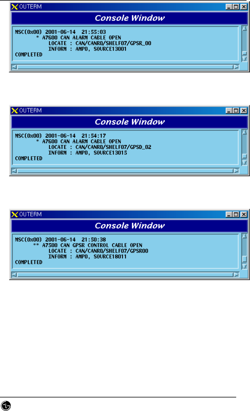
STAREX-IS BSM Manual
Page:628(877)
Issue:1.
0
SMD-011-PMA210
Fig. 5.1-80 TGDB GPSR Alarm Cable Open
2) When a problem occurs in GPSD Alarm Cable
Fig. 5.1-81 TGDB GPSD Alarm Cable Open
3) When a problem occurs in GPSR Control Cable
Fig. 5.1-82 TGDB GPSR Control Cable Open
5.1.1.1.6. FAN and Others
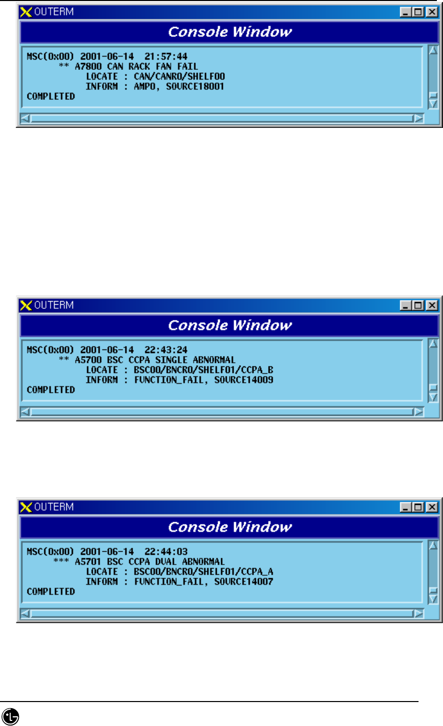
1) When a problem occurs in CAN FAN
STAREX-IS BSM Manual
Page:629(877)
Issue:1.
0
SMD-011-PMA210
Fig. 5.1-83 CAN Rack FAN Fail
5.1.1.2. BSC Occurrence Alarm Message
5.1.1.2.1. CCSB
5.1.1.2.1.1. CCP Processor
1) When A-Side of the duplicated CCP is normal and functional problems occur on
the B-Side board
Fig. 5.1-84 CCSB CCP Single Function Fail
2) When functional problems occur on the A-Side after B-Side of the duplicated
CCP has a functional problem
Fig. 5.1-85 CCSB CCP Dual Function Fail
3) When A-Side of the duplicated CCP is normal and B-Side board is removed