LG Electronics USA 3G1XINBTS STAREX-IS 1900 Indoor BTS User Manual STAREX IS User s Manual
LG Electronics USA STAREX-IS 1900 Indoor BTS STAREX IS User s Manual
Contents
Users Manual Part C
STAREX-IS BSM Manual
Page:399(877)
Issue:1.
0
SMD-011-PMA210
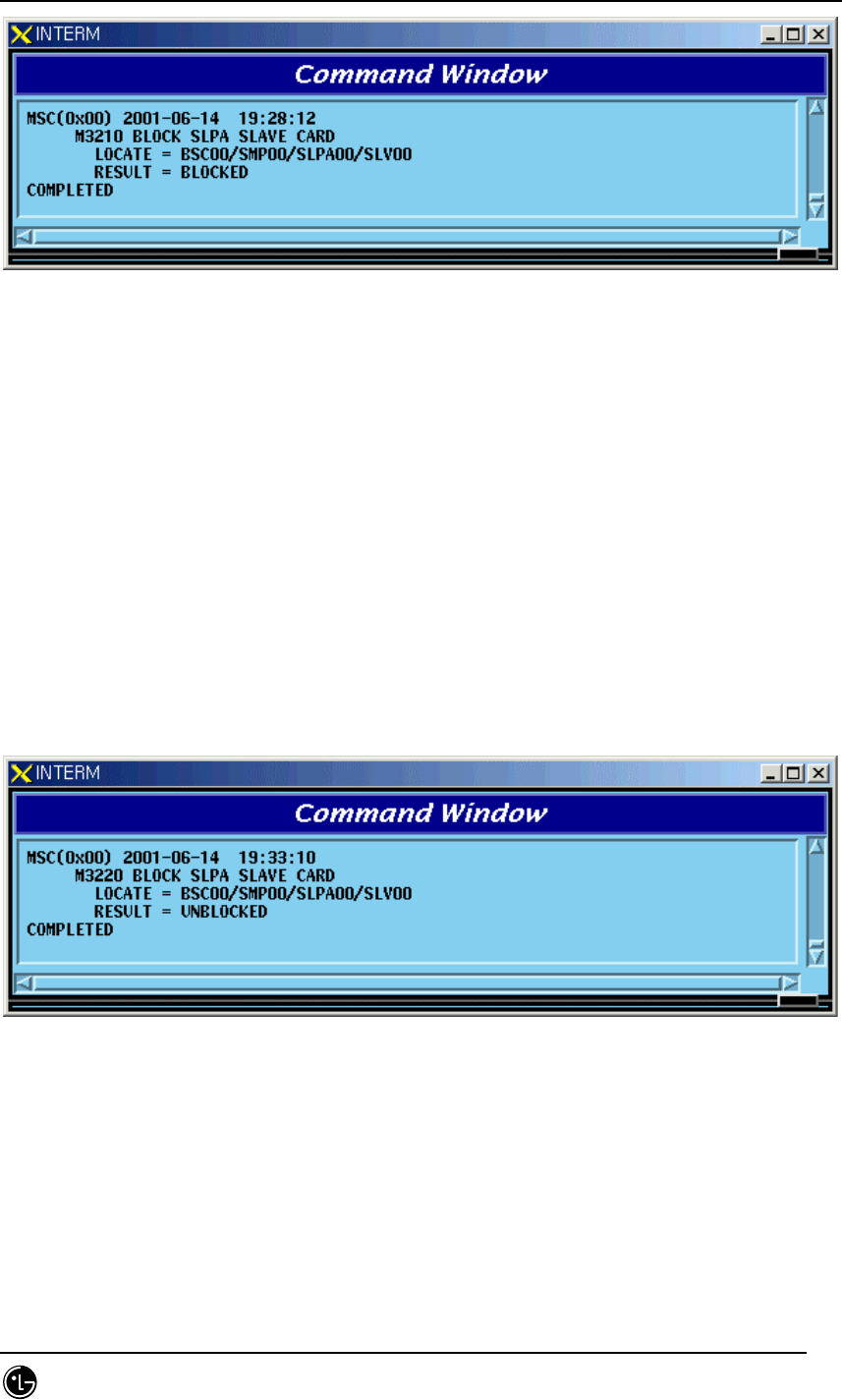
Fig. 4.4-24 Result of SLPA BLOCK Command
4.4.4.8. SLPA UNBLOCK Command
Function to unblock SLPA.
Command : UBLK-SLPA:BSC=a,SMP=b,SLPA=c,[SLV=d];
a : BSC Number(00~11)
b : SMP Number(00~04)
c : SLPA Number(00~17)
d : SLV Number(00~03)
Input : UBLK-SLPA:BSC=0,SMP=0,SLPA=0,SLV=0;
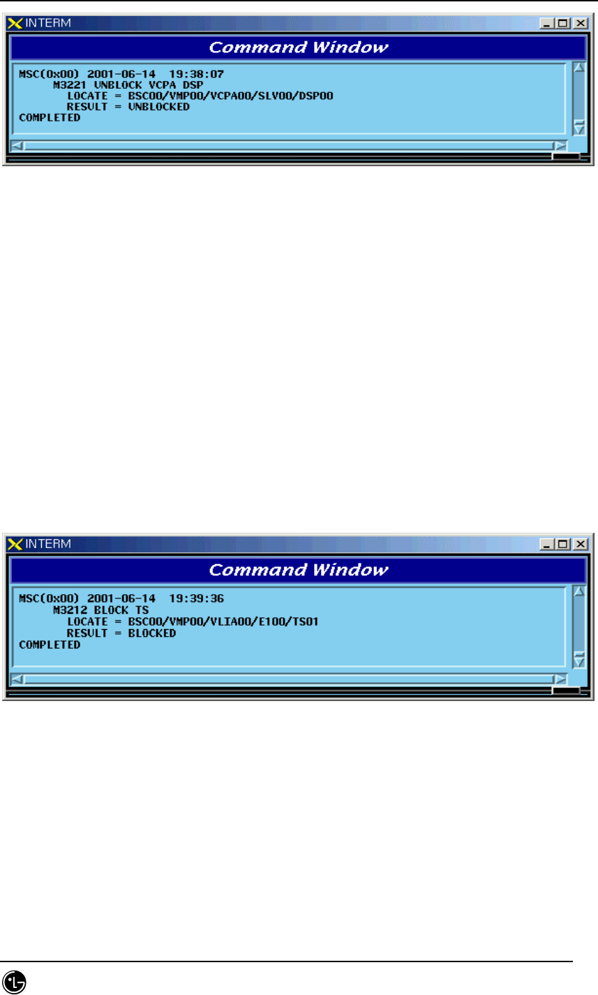
Fig. 4.4-25 Result of SLPA UNBLOCK Command
4.4.4.9. VCPA BLOCK Command
Function to block VCPA.
Command : BLK-VCPA:BSC=a,VMP=b,VCPA=c,[SLV=d],[DSP=e];
a : BSC Number(00~11)

STAREX-IS BSM Manual
Page:400(877)
Issue:1.
0
SMD-011-PMA210
b : VMP Number(00~07)
c : VCPA Number(00~15)
d : SLV Number(00~01)
e : DSP Number(00~03)
Input : BLK-VCPA:BSC=0,VMP=0,VCPA=0,SLV=0,DSP=0;
Fig. 4.4-26 Result of VCPA BLOCK Command
4.4.4.10. VCPA UNBLOCK Command
Function to unblock VCPA
Command : UBLK-VCPA:BSC=a,VMP=b,VCPA=c,[SLV=d],[DSP=e];
a : BSC Number(00~11)
b : VMP Number(00~07)
c : VCPA Number(00~15)
d : SLV Number(00~01)
e : DSP Number(00~03)
Input : UBLK-VCPA:BSC=0,VMP=0,VCPA=0,SLV=0,DSP=0;
STAREX-IS BSM Manual
Page:401(877)
Issue:1.
0
SMD-011-PMA210
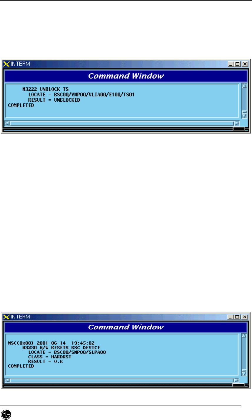
Fig. 4.4-27 Result of VCPA UNBLOCK Command
4.4.4.11. VLIA BLOCK Command
Function to block VLIA.
Command : BLK-VLIA:BSC=0,VMP=0,VLIA=0,[E1=0],[TS=1];
a : BSC Number(00~11)
b : VMP Number(00~07)
c : VLIA Number(0~1)
d : E1 Number(00~15)
e : TS Number(00~31)
Input : BLK-VLIA:BSC=0,VMP=0,VLIA=0,E1=0,TS=1;
Fig. 4.4-28 Result of VLIA BLOCK Command
4.4.4.12. VLIA UNBLOCK Command
Function to unblock VLIA
Command : UBLK-VLIA:BSC=0,VMP=0,VLIA=0,[E1=0],[TS=1];
a : BSC Number(00~11)
b : VMP Number(00~07)
STAREX-IS BSM Manual
Page:402(877)
Issue:1.
0
SMD-011-PMA210
c : VLIA Number(0~1)
d : E1 Number(00~15)
e : TS Number(00~31)
Input : UBLK-VLIA:BSC=0,VMP=0,VLIA=0,E1=0,TS=1;
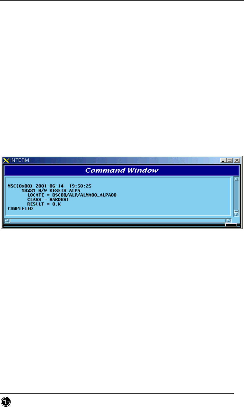
Fig. 4.4-29 Result of VLIA UNBLOCK Command
4.4.4.13. H/W RESET BSC Device Command
Function to reset BSC Device on H/W Level.
Command : RMT-BSC-DEV:BSC=a,PROC=b,DEV=c,ID=d,[SUBID=e],CLS=f;
a : BSC Number(00~11)
b : Processor Name(NCP,SCP,ALP,SMP(00~05),VMP(00~07))
c : Device Name(SLPA,VCPA,VLIA,STIA,ASCA,ASIA,AOTA,ATSA,ALMA)
d : Device ID(00~17)
e : Sub_id(A_SIDE,B_SIDE)
f : Class(HARDRST,ISOLAT,UNISOL)
Input : RMT-BSC-DEV:BSC=0,PROC=SMP00,DEV=SLPA,ID=0,CLS=HARDRST;
STAREX-IS BSM Manual
Page:403(877)
Issue:1.
0
SMD-011-PMA210
Fig. 4.4-30 Result of BSC Device H/W Reset Command
4.4.4.14. H/W RESET ALPA Command
Function to reset ALPA on H/W Level.
Command : RMT-ALPA:BSC=0,ALMA=0,ALPA=0,CLS=HARDRST;
a : BSC Number(00~11)
b : ALMA ID(0~1)
c : ALPA ID(0~4)
d : Class(HARDRST,ISOLAT,UNISOL)
Input : RMT-ALPA:BSC=0,ALMA=0,ALPA=0,CLS=HARDRST;
Fig. 4.4-31 Result of H/W RESET ALPA Command
4.4.5. Bts Device Status Control
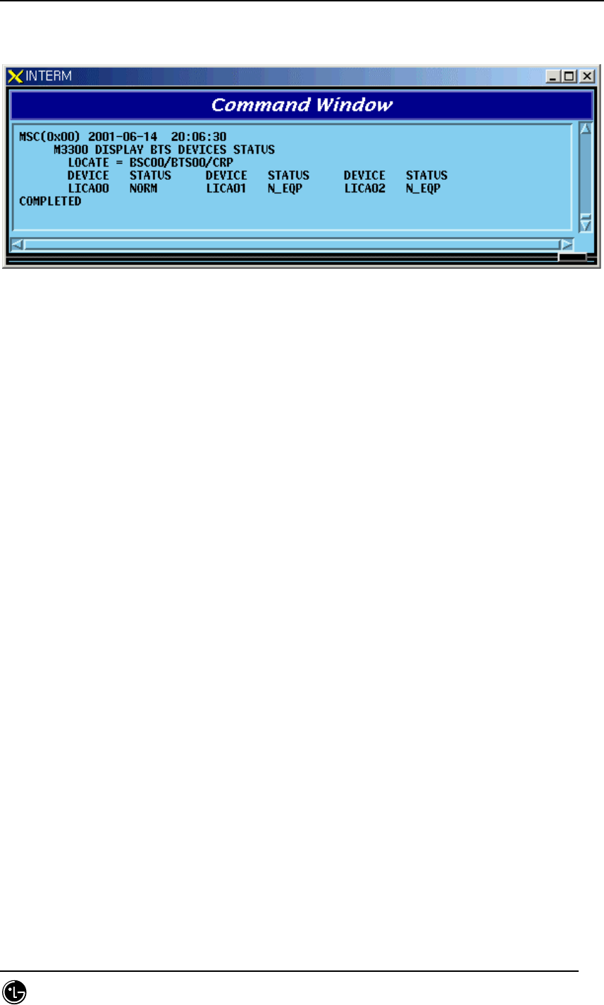
4.4.5.1. BTS Device Status Display Command
Function to display the BTS Device status
Command : DIS-BTS-DEV:BSC=a,BTS=b,PROC=c;
a : BSC Number(00~11)
b : BTS Number(00~47)
c : Processor Name(BSP,BPP,CRP,RCP(00~06)
STAREX-IS BSM Manual
Page:404(877)
Issue:1.
0
SMD-011-PMA210
Input : DIS-BTS-DEV:BSC=0,BTS=0,PROC=CRP;
Fig. 4.4-32 Result of BTS Device Status Display Command
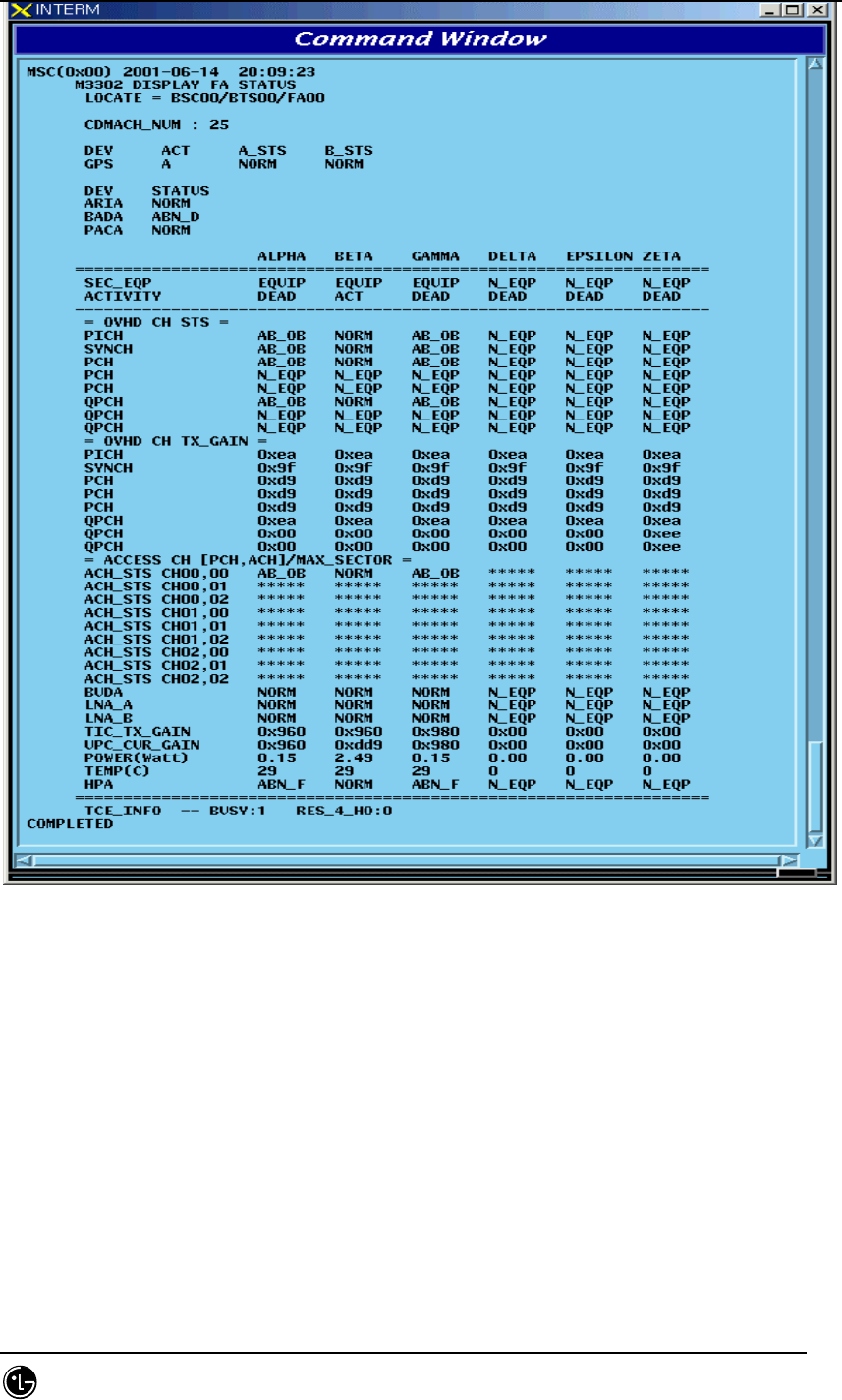
4.4.5.2. FA Status Display Command
Function to display FA Status.
Command : DIS-FA-STS:BSC=a,BTS=bFA=c;
a : BSC Number(00~11)
b : BTS Number(00~47)
c : FA Number(0~7)
Input : DIS-FA-STS:BSC=0,BTS=0,FA=0;
STAREX-IS BSM Manual
Page:405(877)
Issue:1.
0
SMD-011-PMA210
Fig. 4.4-33 Result of FA Status Display Command
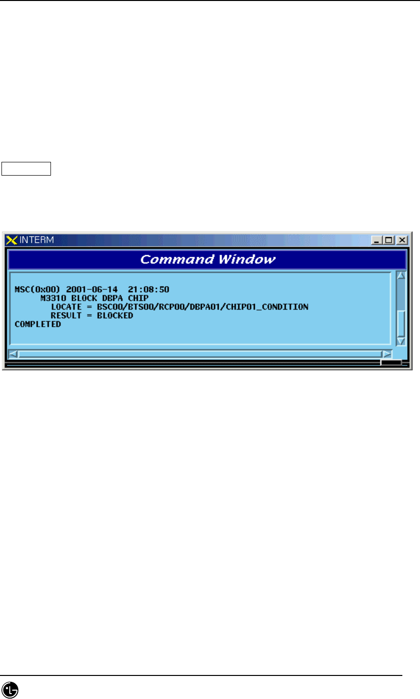
4.4.5.3. BLOCK DBPA Command
Function to block DBPA.
Command : BLK-DBPA:BSC=a,BTS=b,RCP=c,DBPA=d,[CHIP=e],[CONDITION=f];
a : BSC Number(00~11)
b : BTS Number(00~47)
c : RCP Number(0~5)
STAREX-IS BSM Manual
Page:406(877)
Issue:1.
0
SMD-011-PMA210
d : DBPA Number(0~9)
e : CHIP Number(0~1)
f : Select Option(conditional, unconditional)
Conditional : If there is call connected, wait until it is disconnected during timeout and
then block it. If it is not disconnected until timeout, do not block it.
Unconditional : block a call regardless of their presence unconditionally. (The existing
call is disconnected)
Reference : If an OverHead Channel is allocated, do not block a call unconditionally.
Input : BLK-DBPA:BSC=0,BTS=0,RCP=0,DBPA=1,CHIP=1,CONDITION=CONDITION;
Fig. 4.4-34 Result of BLOCK DBPA Command
4.4.5.4. UNBLOCK DBPA Command
Function to unblock DBPA
Command : UBLK-DBPA:BSC=a,BTS=b,RCP=c,DBPA=d,[CHIP=e],[CONDITION=f];
a : BSC Number(00~11)
b : BTS Number(00~47)
c : RCP Number(0~5)
d : DBPA Number(0~9)
e : CHIP Number(0~1)
Input : UBLK-DBPA:BSC=0,BTS=0,RCP=0,DBPA=1,CHIP=1;
STAREX-IS BSM Manual
Page:407(877)
Issue:1.
0
SMD-011-PMA210
Fig. 4.4-35 Result of UNBLOCK DBPA Command
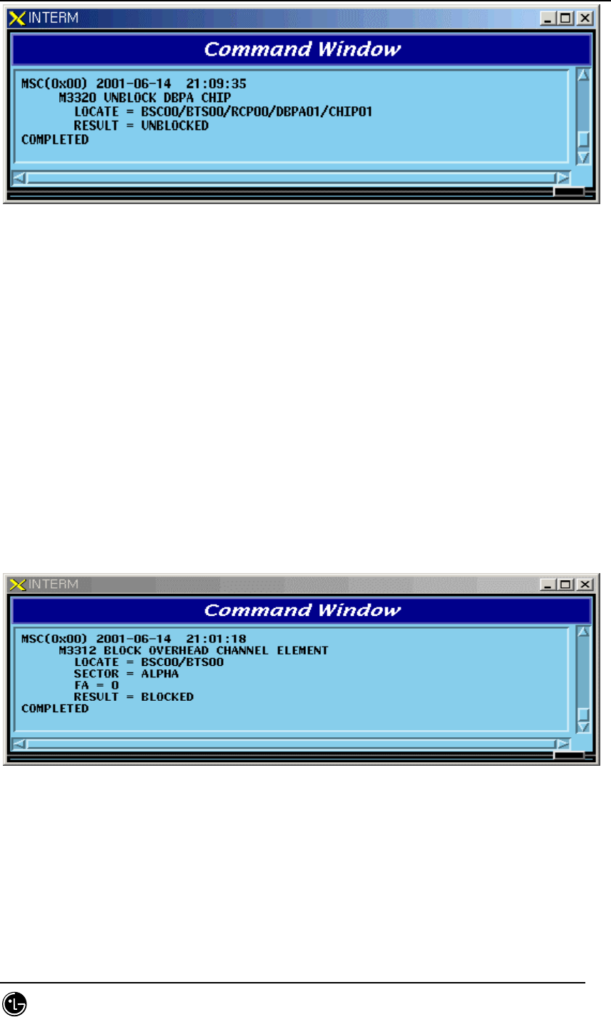
4.4.5.5. BLOCK OverHead Channel Element Display Command
Function to block OverHead Channel Element
Command : BLK-OVHD-CE:BSC=a,BTS=b,SECTOR=c,FA=d;
a : BSC Number(00~11)
b : BTS Number(00~47)
c : SECTOR(ALPHA,BETA,GAMMA,DELTA,EPSILON,ZETA)
d : FA Number(0~5)
Input : BLK-OVHD-CE:BSC=0,BTS=0,SECTOR=ALPHA,FA=0;
Fig. 4.4-36 Result of BLOCK OverHead Channel Element Display
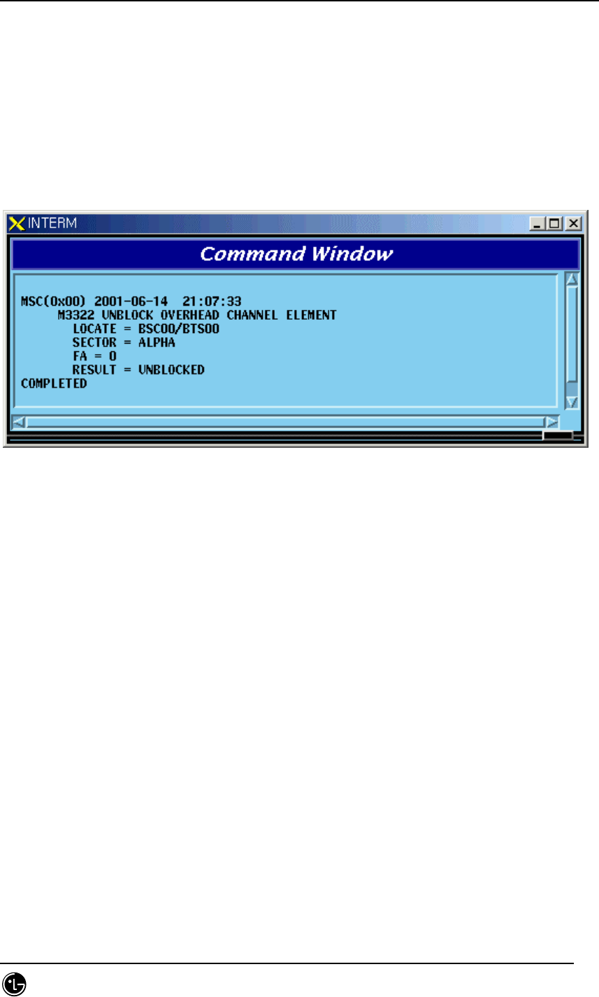
4.4.5.6. UNBLOCK OverHead Channel Element
Function to unblock OverHead Channel Element
STAREX-IS BSM Manual
Page:408(877)
Issue:1.
0
SMD-011-PMA210
Command : UBLK-OVHD-CE:BSC=a,BTS=b,SECTOR=c,FA=d;
a : BSC Number(00~11)
b : BTS Number(00~47)
c : SECTOR(ALPHA,BETA,GAMMA,DELTA,EPSILON,ZETA)
d : FA Number(0~5)
Input : UBLK-OVHD-CE:BSC=0,BTS=0,SECTOR=ALPHA,FA=0;
Fig. 4.4-37 Result of UNBLOCK OverHead Channel Element
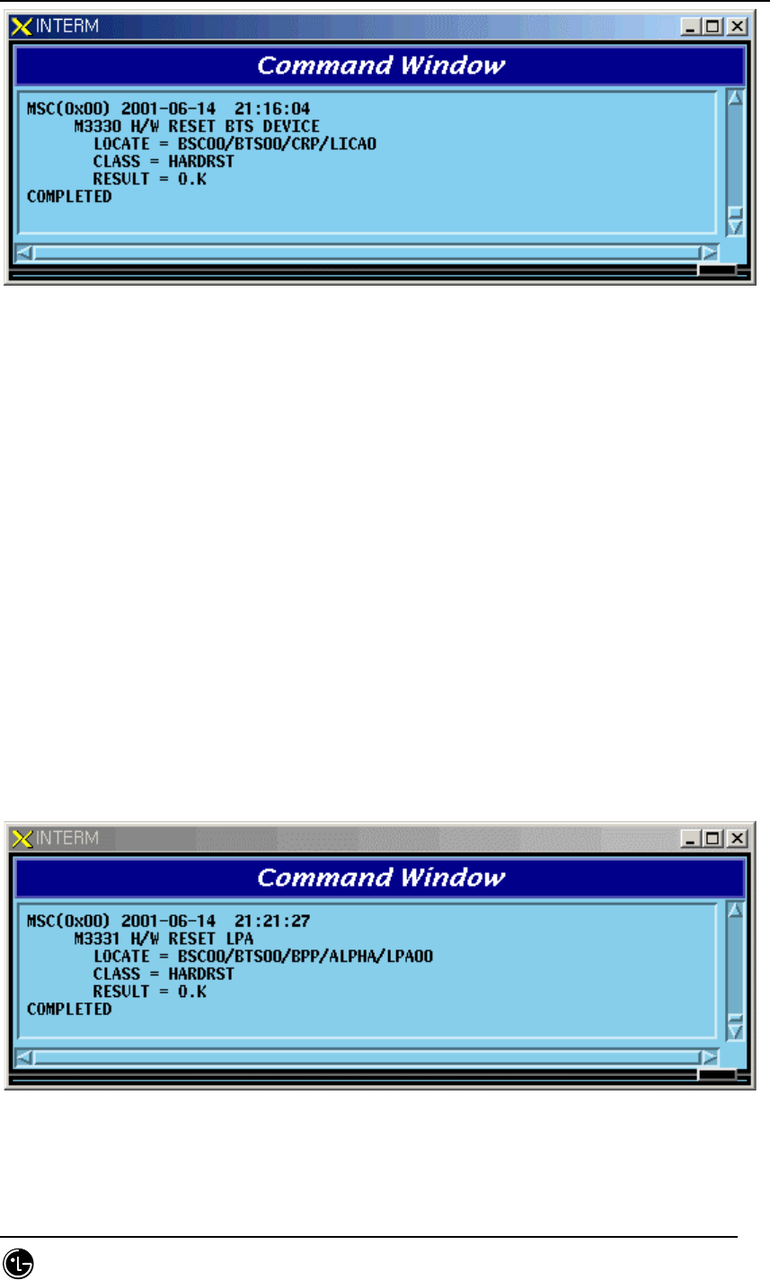
4.4.5.7. H/W RESET BTS Device Command
Function to reset BTS Device on H/W.Level
Command : RMT-BTS-DEV:BSC=a,BTS=b,PROC=c,DEV=d,[ID=e],CLS=f;
a : BSC Number(00~11)
b : BTS Number(00~47)
c : Processor Name(BSP,BPP,CRP,RCP(00~05)
d : Device Name(ARIA,DBPA,BUDA,HPA,PACA,BADA,RISA,BOTA,LICA)
e : Device ID(0~9)
f : Class(HARDRST,ISOLAT,UNISOL)
Input : RMT-BTS-DEV:BSC=0,BTS=0,PROC=CRP,DEV=LICA,ID=0,CLS=HARDRST;
STAREX-IS BSM Manual
Page:409(877)
Issue:1.
0
SMD-011-PMA210
Fig. 4.4-38 Result of H/W RESET BTS Device Command
4.4.5.8. H/W RESET LPA Device Command
Function to reset LPA Device on H/W.Level
Command : RMT-LPA:BSC=a,BTS=b,SECTOR=c,LPA=d,CLS=e;
a : BSC Number(00~11)
b : BTS Number(00~47)
c : SECTOR(ALPHA,BETA,GAMMA,DELTA,EPSILON,ZETA)
d : LPA Number(0~5)
e : Class(HARDRST,ISOLAT,UNISOL)
Input : RMT-LPA:BSC=0,BTS=0,SECTOR=ALPHA,LPA=0,CLS=HARDRST;
Fig. 4.4-39 Result of H/W RESET LPA Device Command
STAREX-IS BSM Manual
Page:410(877)
Issue:1.
0
SMD-011-PMA210
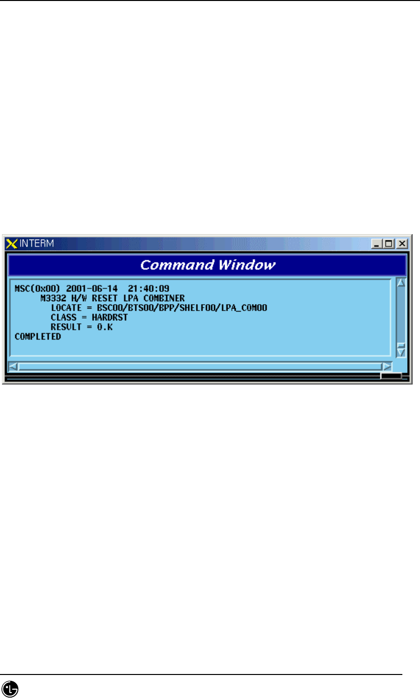
4.4.5.9. H/W RESET LPA Combiner Command
Function to reset the LPA Combiner on H/W Level
Command : RMT-LPA-COM:BSC=a,BTS=b,SHELF=c,COM=d,CLS=e;
a : BSC Number(00~11)
b : BTS Number(00~47)
c : SHELF Number(0~5)
d : Combiner Number(0~2)
e : Class(HARDRST,ISOLAT,UNISOL)
Input : RMT-LPA-COM:BSC=0,BTS=0,SHELF=0,COM=0,CLS=HARDRST;
Fig. 4.4-40 Result of LPA Combiner H/W RESET Command
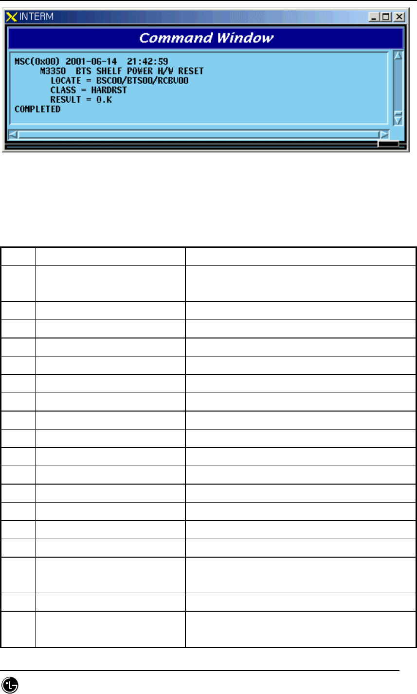
4.4.5.10. BTS SHELF POWER H/W RESET Command
Function to reset BTS SHELF POWER on H/W Level
Command : RMT-BTS-SHF:BSC=a,BTS=b,SHF=c,CLS=d;
a : BSC Number(00~11)
b : BTS Number(00~47)
c : SHELF Name(BANU,RCBU(00~05)
d : Class(HARDRST,ISOLAT,UNISOL)
Input : RMT-BTS-SHF:BSC=0,BTS=0,SHF=RCBU00,CLS=HARDRST;
STAREX-IS BSM Manual
Page:411(877)
Issue:1.
0
SMD-011-PMA210
Fig. 4.4-41 Result of BTS SHELF POWER H/W RESET Command
4.4.6. Status Message Control
Table 4.4-5 Status Message LIST
Codes Definition Description
S3002 CAN CNP/PNP Status Change
Display
When Processor Status changes, it occurs.
S3003 AMP Status Change Display When Processor Status changes, it occurs.
S3004 ALP Status Change Display When Processor Status changes, it occurs.
S3005 CCP Status Change Display When Processor Status changes, it occurs.
S3006 SMP Status Change Display When Processor Status changes, it occurs.
S3007 VMP Status Change Display When Processor Status changes, it occurs.
S3008 PCP Status Change Display When Processor Status changes, it occurs.
S3009 BSC-NCP Status Change Display When Processor Status changes, it occurs.
S3010 BSP Status Change Display When Processor Status changes, it occurs.
S3011 SCP Status Change Display When Processor Status changes, it occurs.
S3012 BPP Status Change Display When Processor Status changes, it occurs.
S3013 RCP Status Change Display When Processor Status changes, it occurs.
S3017 CRP Status Change Display When Processor Status changes, it occurs.
S3020 PMP Status Change Display When Processor Status changes, it occurs.
S3201 CNP ASIA Status Change Display Displayed upon device status change
S3202 CNP ASCA Status Change
Display
Displayed upon device status change
S3205 PNP ASIA Status Change Display Displayed upon device status change
S3206 PNP ASCA Status Change
Display
Displayed upon device status change

STAREX-IS BSM Manual
Page:412(877)
Issue:1.
0
SMD-011-PMA210
S3209 PCP BCRA Status Change
Display
Displayed upon device status change
S3210 PMP BCRA Status Change
Display
Displayed upon device status change
S3211 AMP GPSR Status Change
Display
Displayed upon device status change
S3220 NCP ASIA Status Change Display Displayed upon device status change
S3221 NCP ASCA Status Change
Display
Displayed upon device status change
S3222 NCP ATSA Status Change
Display
Displayed upon device status change
S3224 ALP ALMA Status Change
Display
Displayed upon device status change
S3230 BSP GPS Status Change Display Displayed upon device status change
S3501 CCP Overload State Change
Display
Displayed when overload status is generated,
released and changed owing to load change in
CCP
S3502 BSP Overload State Change
Display
Displayed when overload status is generated,
released and changed owing to load change in
BSP
STAREX-IS BSM Manual
Page:413(877)
Issue:1.
0
SMD-011-PMA210
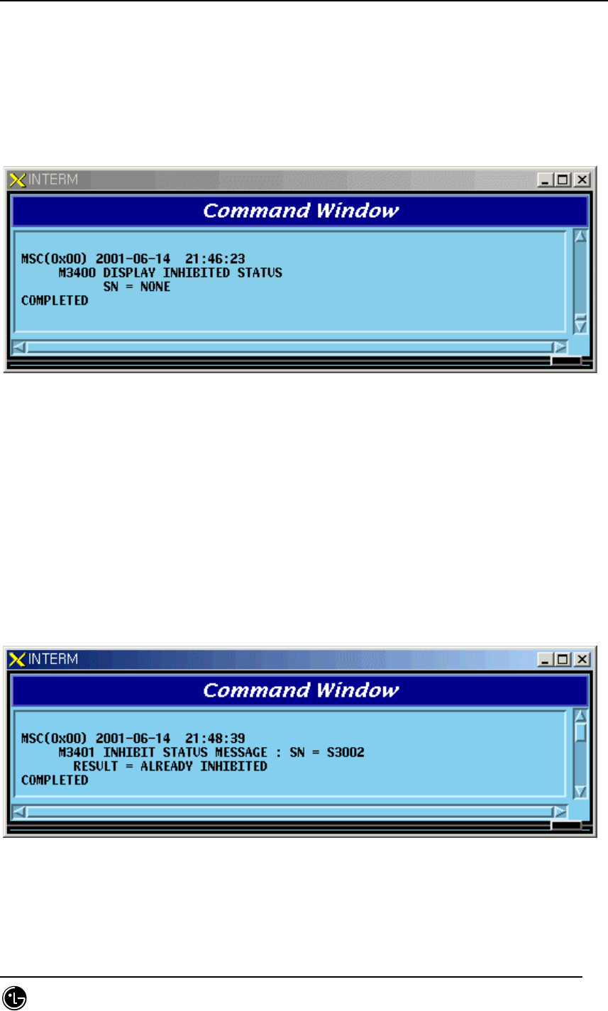
4.4.6.1. Inhibited Status Message Display Command
Function to display Status Message whose display to Outterm is inhibited
Command : DIS-INH-STS;
Input : DIS-INH-STS;
Fig. 4.4-42 Result Inhibited Status Message Display Command
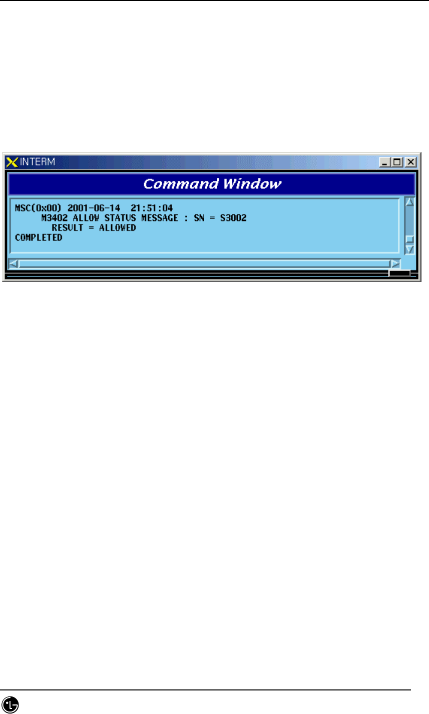
4.4.6.2. Status Message Display Inhibition Command
Function to inhibit Status Message display
Command : INH-STS-MSG:SN=a;
a: SN Number(ALL,S3002~S3020,S3201~S3230, S3501,S3502)
Input : INH-STS-MSG:SN=S3002;
Fig. 4.4-43 Result of Status Message Display Inhibition Command
STAREX-IS BSM Manual
Page:414(877)
Issue:1.
0
SMD-011-PMA210
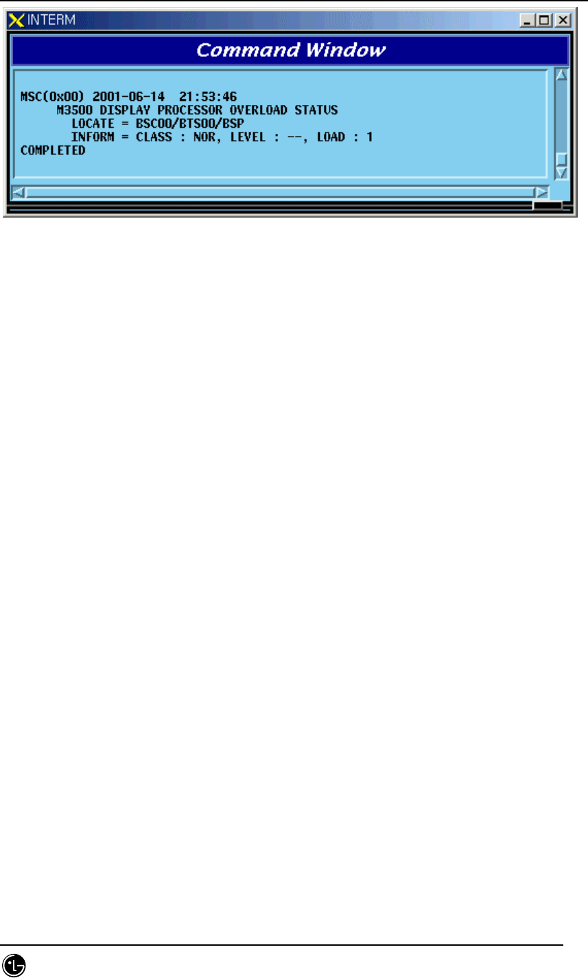
4.4.6.3. Allow Inhibited Message Command
Function to allow display of Status Message whose display to Outterm is inhibited
Command : ALW-STS-MSG:SN=a;
a: SN Number(ALL,S3002~S3020, S3201~S3230, S3501,S3502)
Input : ALW-STS-MSG:SN=S3002;
Fig. 4.4-44 Result of Inhibited Message Display Allow Command
4.4.7. Overload Status Control
4.4.7.1. Processor Overload Status Display Command
Function to display processor Overload Status
Command : DIS-OVLD-STS:[BSC=a],[BTS=b],PROC=c;
a : BSC Number(00~11)
b : BTS Number(00~47)
c : Processor Name(CCP,BSP)
Input : DIS-OVLD-STS:BSC=0,BTS=0,PROC=BSP;
STAREX-IS BSM Manual
Page:415(877)
Issue:1.
0
SMD-011-PMA210
Fig. 4.4-45 Result of Processor Overload Status Display Command
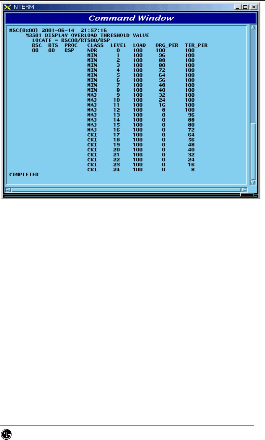
4.4.7.2. Overload Threshold Value Display Command
Function to display Overload Threshold Value
Command : DIS-OVLD-THR:BSC=a,[BTS=b],PROC=c;
a : BSC Number(00~11)
b : BTS Number(00~47)
c : Processor Name(CCP,BSP)
Input : DIS-OVLD-THR:BSC=0,BTS=0,PROC=BSP;
STAREX-IS BSM Manual
Page:416(877)
Issue:1.
0
SMD-011-PMA210
Fig. 4.4-46 Result of Overload Threshold Value Display Command
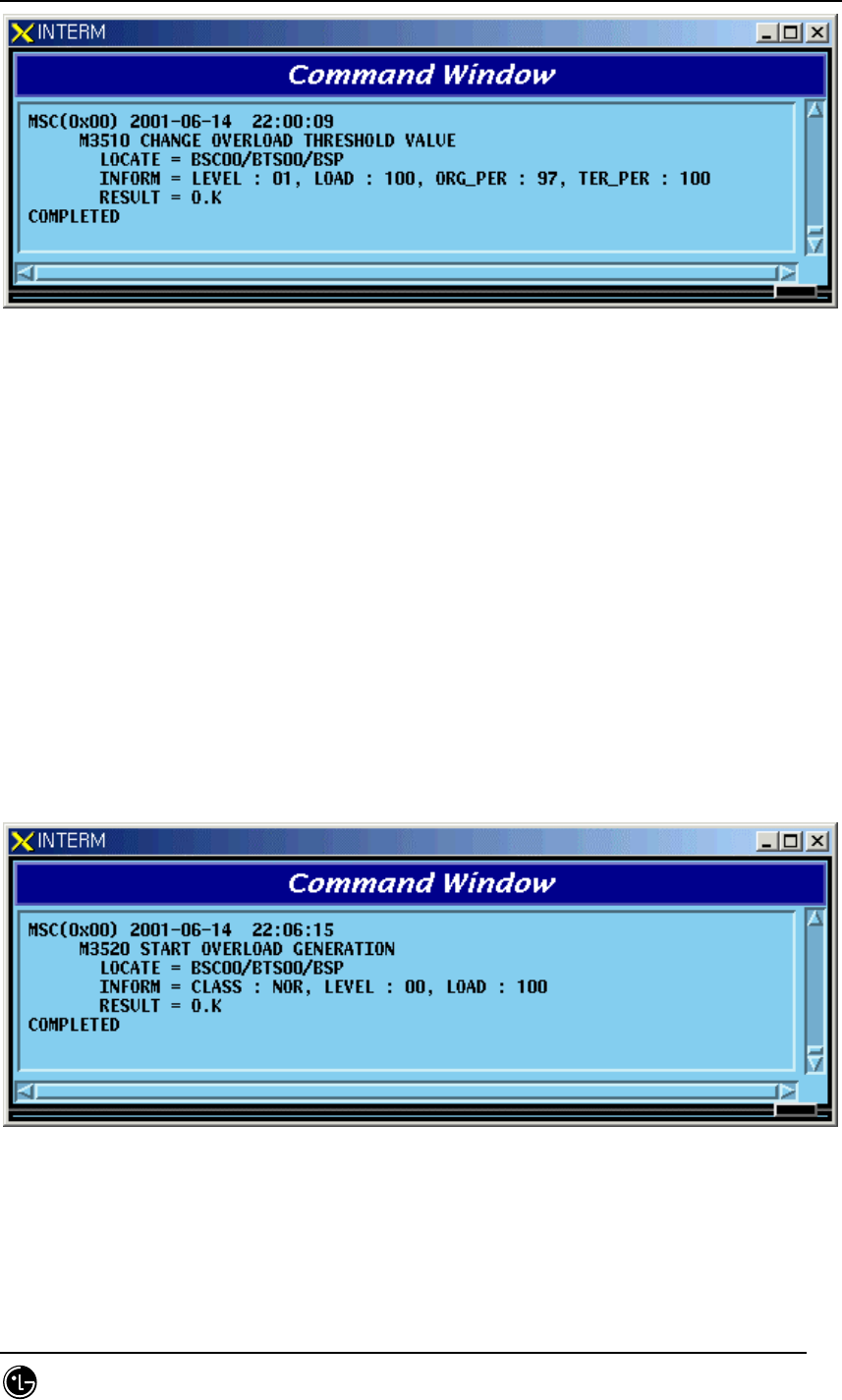
4.4.7.3. Overload Threshold Value Change Command
Function to change Overload Threshold Value.
Command:
CHG-OVLD-THR:BSC:a,[BTS=b],LEVEL=c,[LOAD=d], [ORG_PER=e],[TER_PER=f];
a : BSC Number(00~11)
b : BTS Number(00~47)
c : LEVEL(0~100)
d : LOAD(0~100)
e : ORG_PER(0~100)
f : TER_PER(0~100)
Input :
CHG-OVLD-THR:BSC:0,BTS=0,LEVEL=0,LOAD=100, ORG_PER=97,TER_PER=100;
STAREX-IS BSM Manual
Page:417(877)
Issue:1.
0
SMD-011-PMA210
Fig. 4.4-47 Result of Overload Threshold Value Change Command
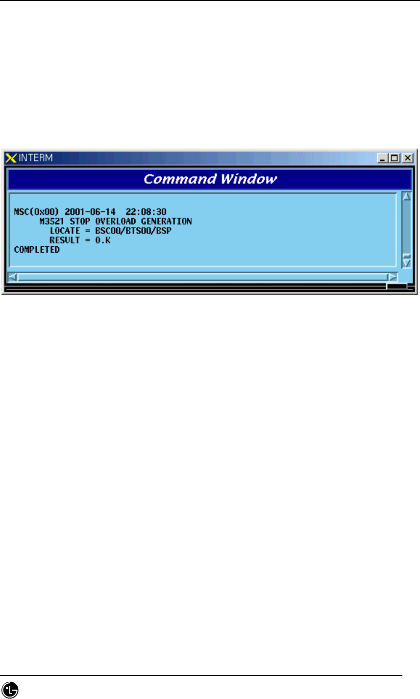
4.4.7.4. Overload Generation Test Command
Function to generate Overload threshold value
Command : STRT-OVLD-GEN:BSC=a,[BTS=b],PROC=c,LEVEL=d;
a : BSC Number(00~11)
b : BTS Number(00~47)
c: Processor Name(CCP,BSP)
d: LEVEL(0~24)
Input : STRT-OVLD-GEN:BSC=0,BTS=0,PROC=BSP,LEVEL=0;
Fig. 4.4-48 Result of Overload Generation Test Command
4.4.7.5. Overload Generation Test STOP Command
STAREX-IS BSM Manual
Page:418(877)
Issue:1.
0
SMD-011-PMA210
Function to stop the Overload Generation Test
Command : STOP-OVLD-GEN:BSC=a,[BTS=b],PROC=c,LEVEL=d;
a : BSC Number(00~11)
b : BTS Number(00~47)
c: Processor Name(CCP,BSP)
d: LEVEL(0~24)
Input : STOP-OVLD-GEN:BSC=0,BTS=0,PROC=BSP,LEVEL=0;
Fig. 4.4-49 Result of Overload Generation Test STOP Command
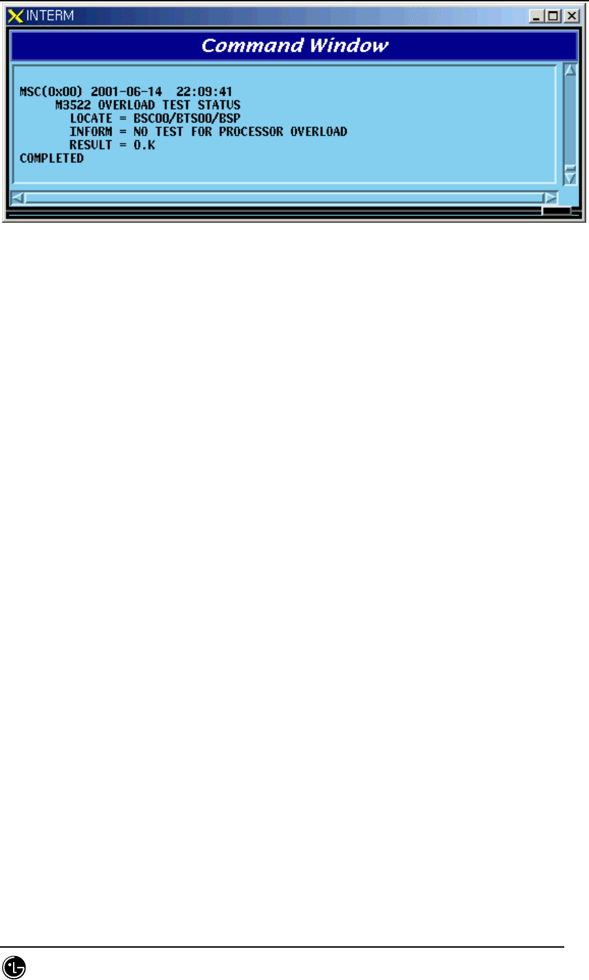
4.4.7.6. Command to Display Whether or not the Overload Generation
Test is performed
Function to find out whether the Overload Display Test is performed
Command : DIS-OVLD-GEN:BSC=a,[BTS=b],PROC=c,LEVEL=d;
a : BSC Number(00~11)
b : BTS Number(00~47)
c: Processor Name(CCP,BSP)
d: LEVEL(0~24)
Input : DIS-OVLD-GEN:BSC=0,BTS=0,PROC=BSP,LEVEL=0;
STAREX-IS BSM Manual
Page:419(877)
Issue:1.
0
SMD-011-PMA210
Fig. 4.4-50 Command to Determine Whether to Perform the Overload Generation Test

STAREX-IS BSM Manual
Page:420(877)
Issue:1.
0
SMD-011-PMA210
4.5. Test Command
4.5.1. On-Line Test-related Command
On-Line Test is a function that allows a test to be performed automatically at a
specific time on a specific day and includes the following: Vocoder, CE, BTS Markov
test and VSWR test. The tests of CE, BTS Markov and VSWR find out presence of
faults in hardware of Channel Elements in BTS and the test function for radio
environment, and the Vocoder test finds out presence of faults in hardware of
Vocoder in BSC. Because the tests of CE, Vocoder, BTS Markov, and VSWR seize call
resources, the user designates the specific time (idlest time) during the time that only
a test is allowed. The tests of CE, BTS Markov, and VSWR are conducted under the
supervision of BSP while the Vocoder test is conducted under the supervision of CCP.
If the user designates the day and start/ending time for the Online test, and the ID
scope of the board to be tested, BSM becomes the designated time of the designated
day and if the test is in the ALLOW status, it commands the corresponding Processor
to start/end the test.
The performance of the On-Line test is decided by Command INH-ONL-TEST (Inhibit
Test), ALW-ONL-TEST(Allow Test). Only when the status is designated as “ALLOW”
by ALW-ONL-TEST Command, On-Line test is performed. The Command of INH-
ONL-TEST inhibits the test. Besides these two Commands, there is a command to stop
the test by each Test(CE : STS-CE-ONL, Vocoder : STS-VCE-ONL, BTS Markov :
STS-MKV-ONL, VSWR : STS-VSWR-ONL). If the test was stopped by INHIBIT
Command, the On-Line Test is not performed even if the designated time of the
designated day of the week arrives because inhibit/allow status is changed to
“INHIBIT”. ,. However, if the Test was stopped by the above listed STOP Command,
the On-Line Test that was performed on that day only comes to a halt and at the
designated time of the next designated day of the week the On-Line Test is to be
performed normally because DB Flag that indicates the status of INHIBIT/ALLOW is
not changed
.
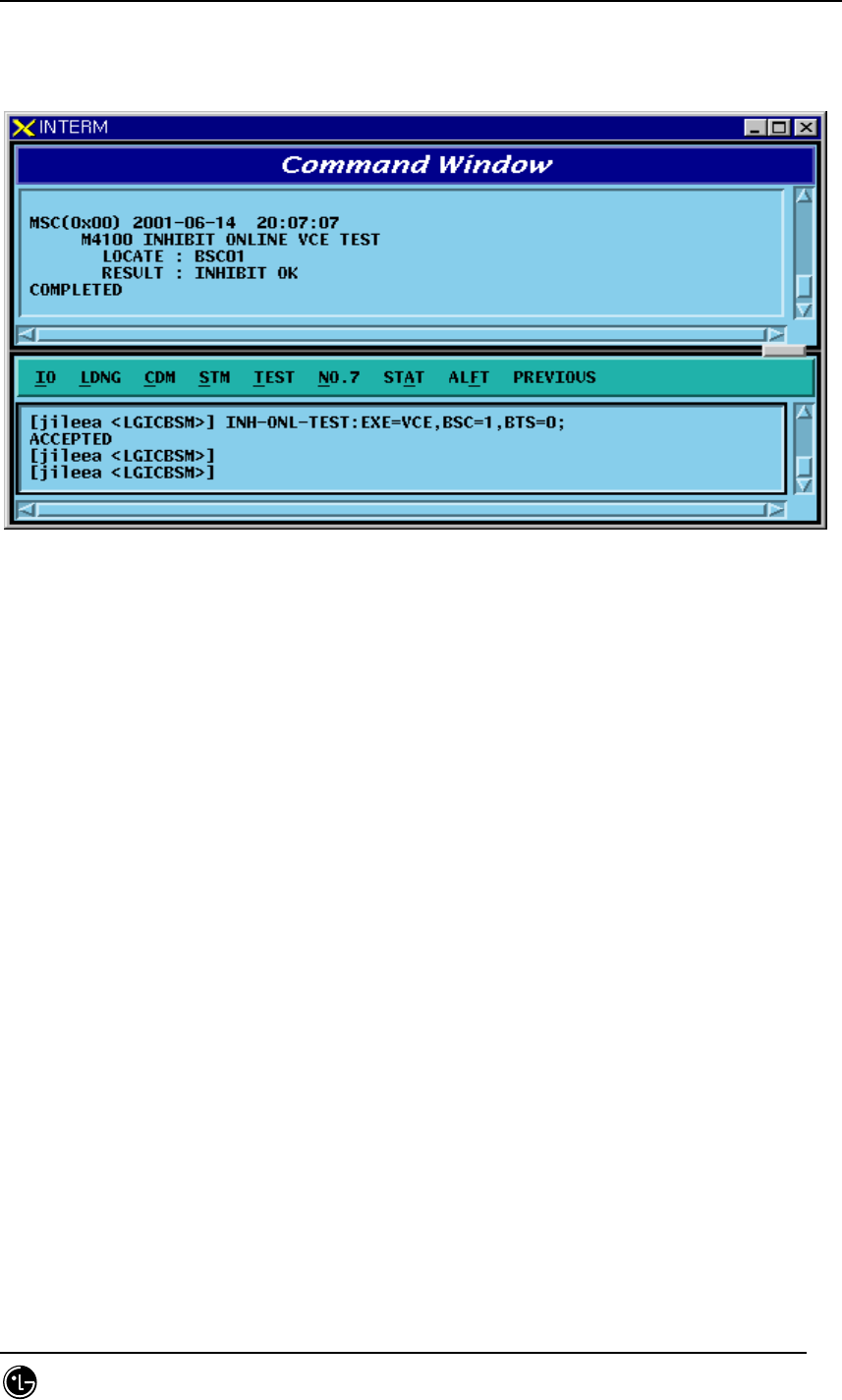
4.5.1.1. On-Line Test Inhibit Command
It is the function that inhibits On Line Test for CE, Vocoder, BTS Markov, and VSWR
test. In the cases of CE, BTS Markov, and VSWR test, input the corresponding BTS
number and in the case of Vocoder test, input the corresponding BSC number.
• Command INH-ONL-TEST:EXE=a, BSC=b,[BTS=c];
a: VCE/CE/MKV/VSWR
STAREX-IS BSM Manual
Page:421(877)
Issue:1.
0
SMD-011-PMA210
b: BSC number (0~11)
c: BTS number (0~47)
• Input/Output
Fig. 4.5-1 Result of Test Inhibit Command Execution
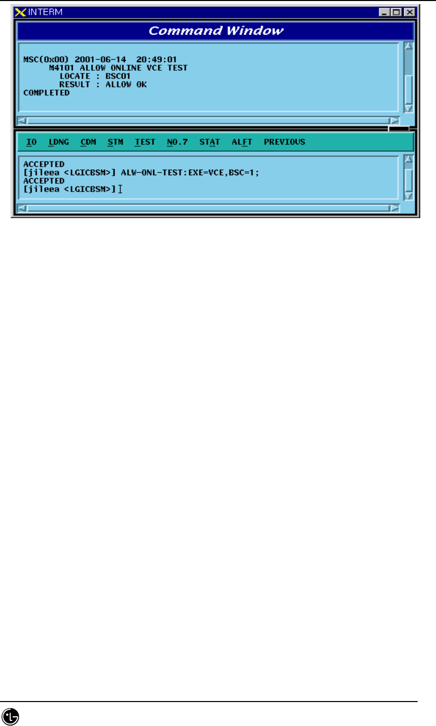
4.5.1.2. On-Line Test Allow Command
Function that allows Online Test for CE, Vocoder, BTS Markov, and VSWR test
For CE, BTS Markov and VSWR test, input the corresponding BTS number and for
Vocoder test, input corresponding BSC number.
• Command ALW-ONL-TEST:EXE=a,BSC=b[BTS=c];
a: VCE/CE/MKV/VSWR
b: BSC number (0~11)
c: BTS number (0~47)
• Input/Output
STAREX-IS BSM Manual
Page:422(877)
Issue:1.
0
SMD-011-PMA210
Fig. 4.5-2 Result of Test Allow Command Execution
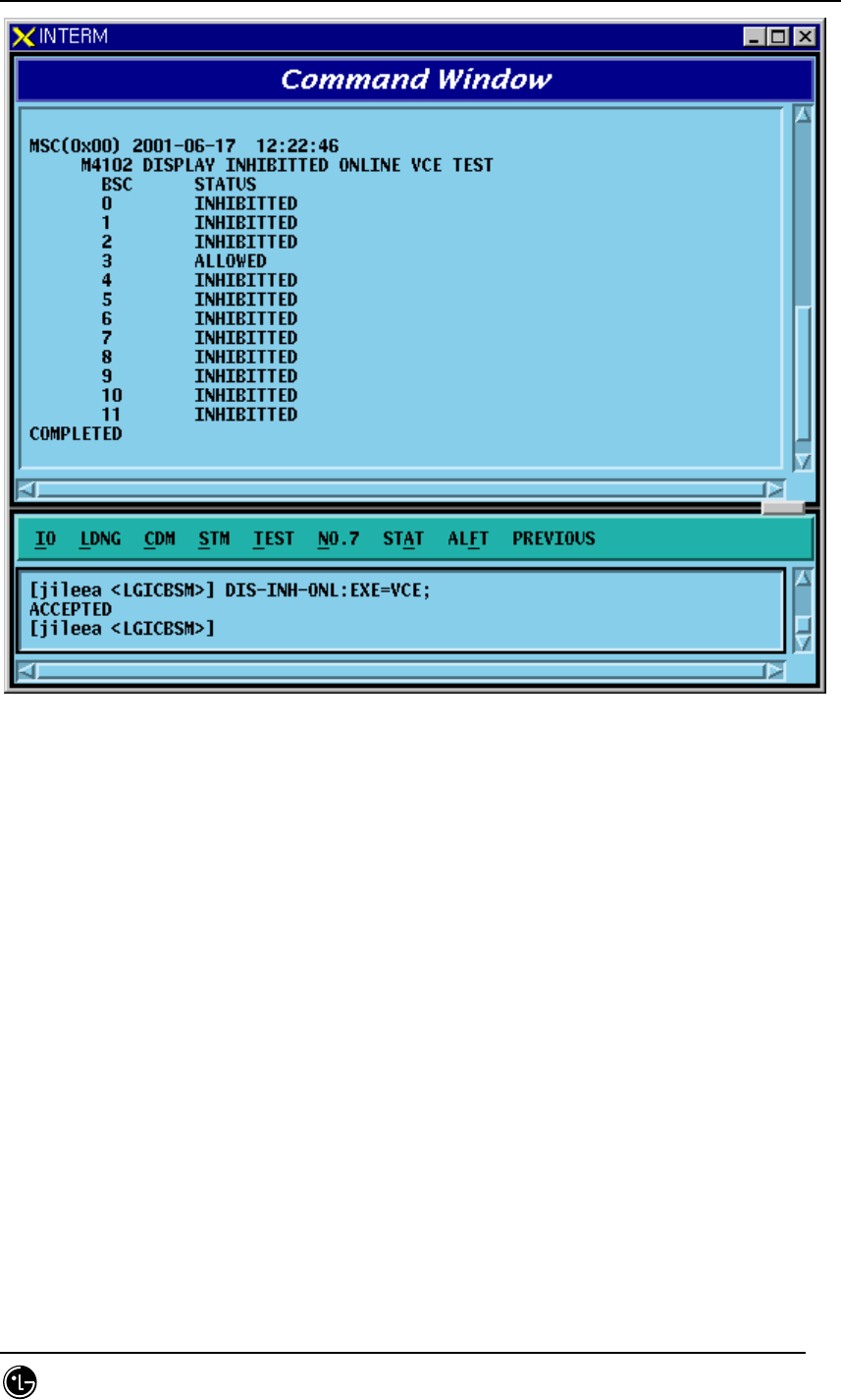
4.5.1.3. On-Line Test Inhibit Item Display Function
Function to display the inhibit of the on line test for the specific tests among the on-
line tests by BSC and BTS. For Vocoder test, it displays Inhibit status. In case of CE,
BTS Markov and in case of the VSWR test, it displays the status by BTS.
• Command DIS-INH-ONL:EXE=a,BSC=b[BTS=c];
a: VCE/CE/MKV/VSWR
b: BSC number (0~11)
c: BTS number (0~47)
• Input/Output
STAREX-IS BSM Manual
Page:423(877)
Issue:1.
0
SMD-011-PMA210
Fig. 4.5-3 Result of Test Inhibit/Allow List Display Command Execution

STAREX-IS BSM Manual
Page:424(877)
Issue:1.
0
SMD-011-PMA210
4.5.2. Test-related to Channel Element
Channel Element Test is performed in BIT(Built In Test) for each chip. The types of
BIT Test are as follows:
- Bus Interrupt Test
- ChipX16 Test
- PP2S Test
- PCG Test
This BIT Test is normally performed on Chip with OVHD channel and Chip seized with
a call and the result is reported to BSM.
Table 4.5-1CE Test Result Message
On-Demand DESCRIPTION
BIT_OK
BIT_BUS_FAIL
BIT_INT_FAIL
BIT_CHIPX16_FAIL BIT_PP2S_FAIL
BIT_PCG_FAIL
BIT_RAM_FAIL
BIT_PROGRESS_FAIL
NORMAL
BUS INTERFACE TEST FAIL
INTERNAL INTERRUPT TEST FAIL
CHIPX16 TEST FAIL
PCG TEST FAIL
MEMORY TEST FAIL
TEST PERFORMING FAIL
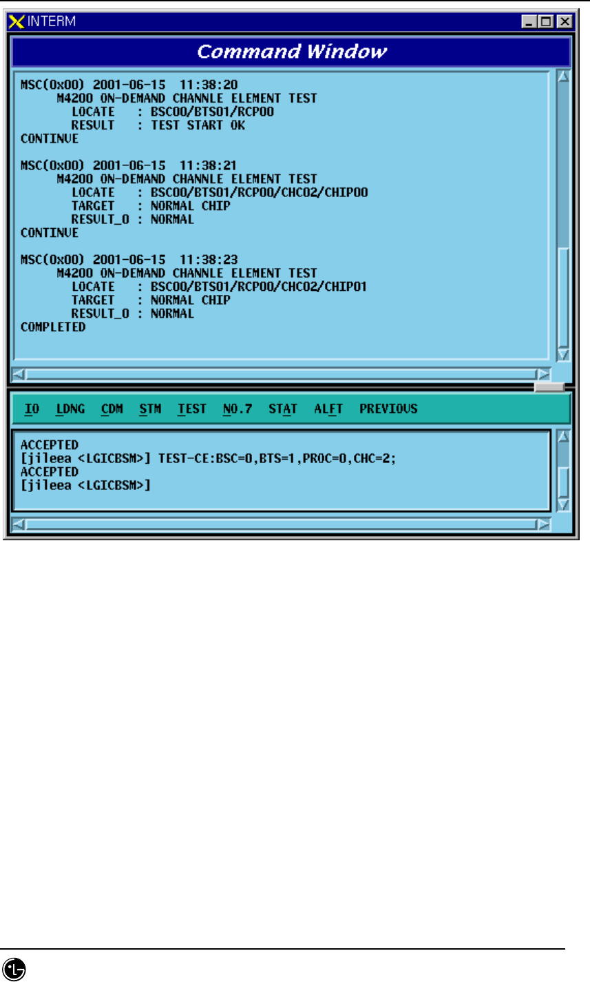
4.5.2.1. Channel Element Test Function
Function to perform BIT test by CHC and CHIP unit.
• Command TEST-CE :BSC=a ,BTS=b ,PROC=c [,CHC=d] [,CHIP=e];
a: BSC number (0~11)
b: BTS number (0~47)
c: RCP number (0~9)
d: Channel Card Number (0~9)
e: Chip Number (0~1)
• Input/Output
STAREX-IS BSM Manual
Page:425(877)
Issue:1.
0
SMD-011-PMA210
Fig. 4.5-4 Result of CE BIT Test Execution

STAREX-IS BSM Manual
Page:426(877)
Issue:1.
0
SMD-011-PMA210
4.5.3. Vocoder Test Function
The types of Vocoder Tests are as follows:
o DSP H/W Test
- Determines the presence of problems in ROM, RAM, ALU of DSP in
Vocoder
- Diagnosis the presence of problems by checking Checksum, Read/Write,
Flag Set, etc.
- Caused by defective DSP Chip
o Timing Module Test (Channel Test)
- VCP generates Vocoder and Tx.Rx Timing by using MFP(Multiple-
Function Processor) in order to exchange voice data with SLP every
20ms.
- It judges the presence of problems in Vocoder counter by checking the
generated Rx.Tx timing.
o Loopback Test (Channel Test)
- It is a test to decide whether or not the status of Loop used in Qcelp
Algorithm test is normal and its Loop section has VLIA, VCMA and VCPA.
All of them should be normal to execute the Qcelp Algorithm test. VCP
generates Test Pattern and by checking the Loopbacked result, it decides
an absence of failure.
o QCELP Algorithm Test (Channel Test)
- Due to intermittent problems in Vocoder and VCPA Card H/W, a
phenomenon that a call is not heard bi-directionally occurs. In order to
prevent this from happening, Qcelp Algorithm is tested. This test
determines whether Vocoder is normal by testing whether status
transition of Qcelp Algorithm is normally performed by the state. .
Table 4.5-2 Vocoder Test Result
On-Demand / On-Line Message Description

STAREX-IS BSM Manual
Page:427(877)
Issue:1.
0
SMD-011-PMA210
FLT_DSP_HW
FLT_CLK
FLT_VCPA_LOOPBACK
FLT_VCMA_LOOPBACK
FLT_VLIA_LOOPBACK
FLT_QCELP_ST0
FLT_QCELP_ST1
FLT_QCELP_ST2
FLT_QCELP_ST3
DSP HW test Fault
Timing Module test Fault
Vocoder Processor Loopback test Fault
Vocoder Master board Loopback test Fault
Vocoder Line interface Loopback test Fault
Qcelp Algorithm test Fault state0
Qcelp Algorithm test Fault state1
Qcelp Algorithm test Fault state2
Qcelp Algorithm test Fault state3
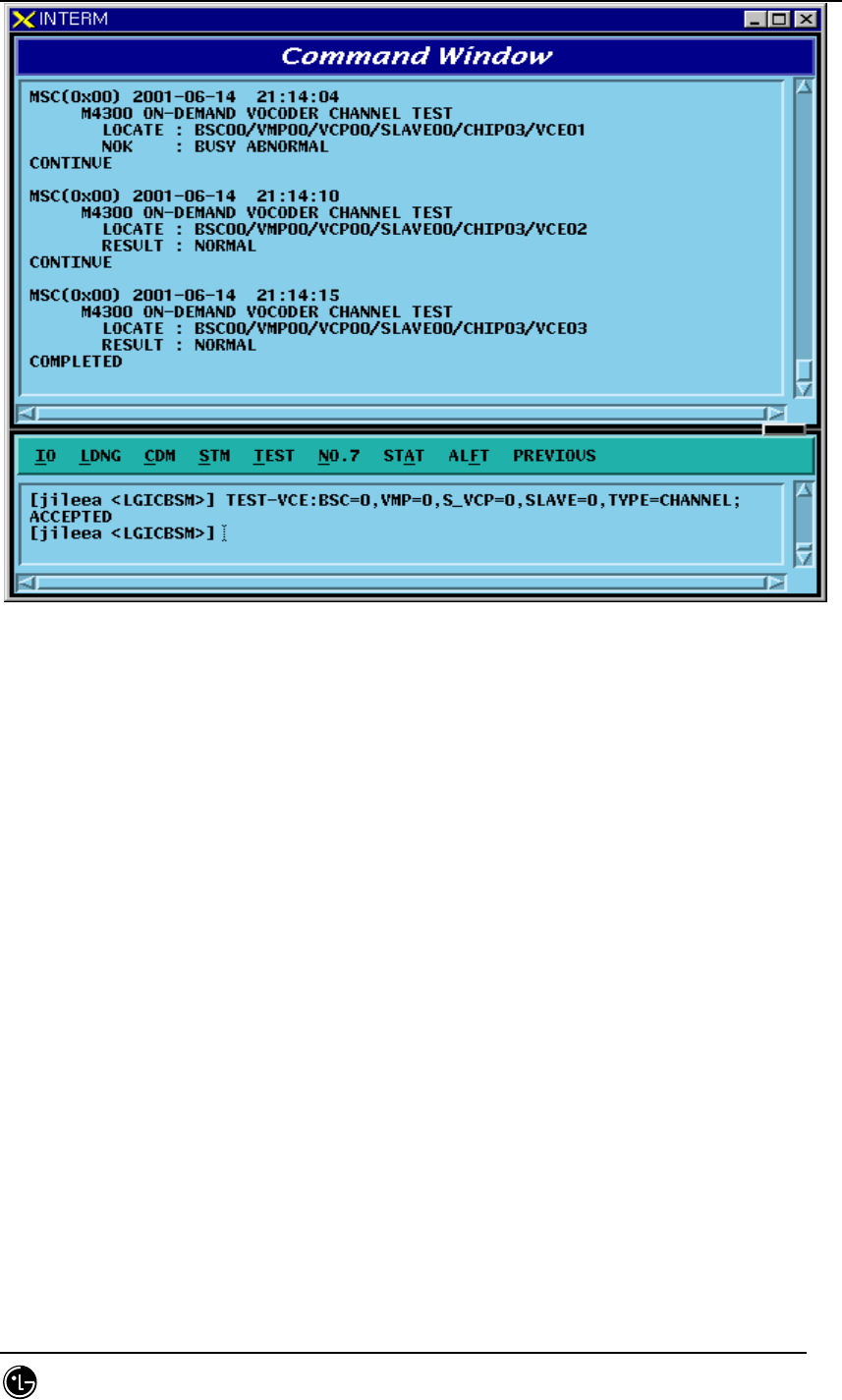
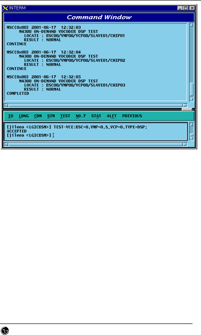
4.5.3.1. On-Demand Vocoder Test Function
Function to test Vocoder DSP or Channel by VCP/SLAVE/CHIP unit.
• Command TEST-VCE: BSC=a ,VMP=b ,S_VCP=c [,E_VCP=d] [,SLAVE=e] [,CHIP=f]
[,VCE=g] ,TYPE=h [,OPTION=i] [,WAIT_T=j]
a: BSC number (0~11)
b: VMP number (0~7)
c, d: VCP number (0~15)
e: SLAVE number (0~1)
f : CHIP number (0 ~ 3)
h: Test Type(DSP, Channel)
i: Test Option(SKIP, RELEASE, WAIT_THEN) => These are options
used to test channels when a call is seized, and SKIP does not perform a test
when a call is seized but skips. With option RELEASE, it disconnects a call
when a call is seized and then performs a test. With option WAIT_THEN, it
waits as long as j time is allowed and if a call is released within the designated
time, then it goes on with a test. However, if a call is not released, it skips.
J: Wait Time(5~300 sec)
• Input/Output
STAREX-IS BSM Manual
Page:428(877)
Issue:1.
0
SMD-011-PMA210
Fig. 4.5-5 Result of On-Demand Vocoder Test(Channel Type) Execution
STAREX-IS BSM Manual
Page:429(877)
Issue:1.
0
SMD-011-PMA210
Fig. 4.5-6 Result of On-Demand Vocoder Test(DSP Type) Execution
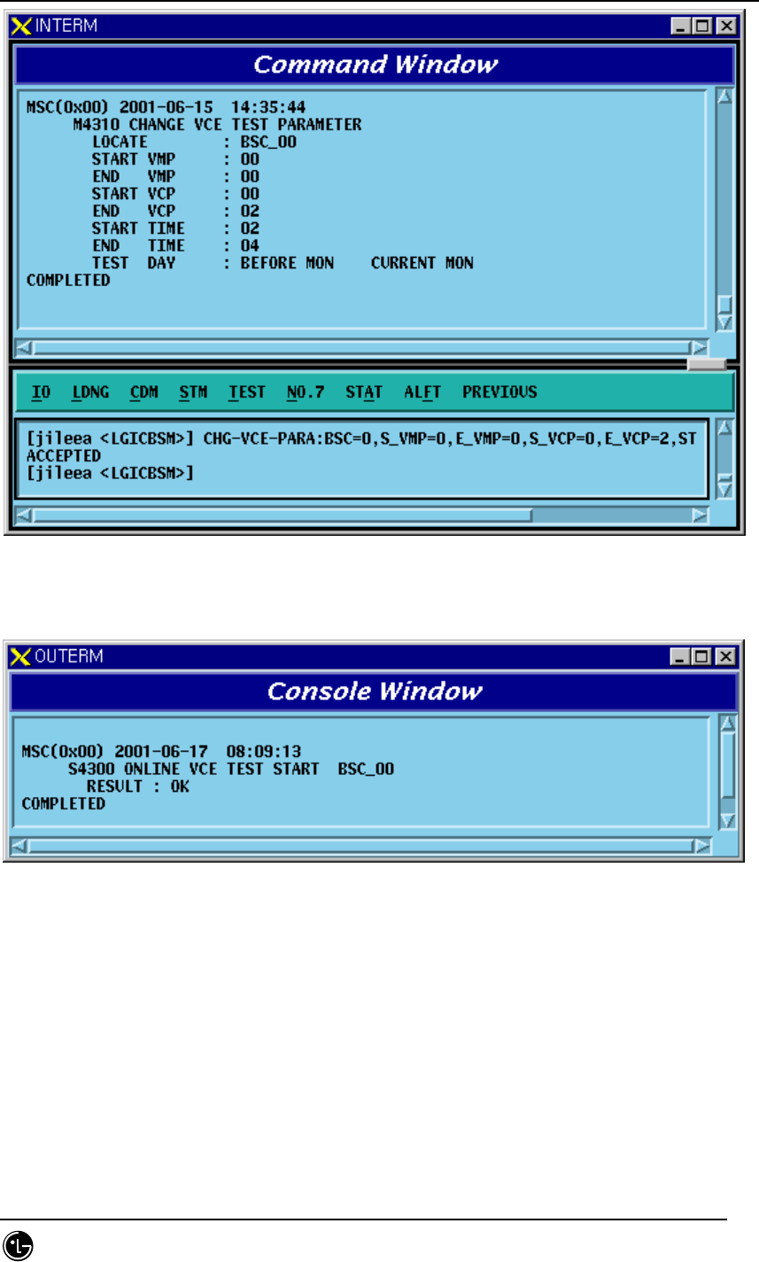
4.5.3.2. Parameter Change Command Related to On-Line Vocoder Test
Function to change On-Line Vocoder test start/ending time, test day and the scope of
VMP/VCP to be tested.
• Command CHG-VCE-PARA :BSC=a ,S_VMP=b [,E_VMP=c] ,S_VCP=d [,E_VCP=e]
[,STI ME=f] [,ETIME=g] ,WDAY=h;
a: BSC number (0~11)
b,c: VMP number(0~7)
d,e: VCP number(0~15)
f: On-Line test Start Time (0~23 Hour)
g: On-Line test End Time (1~24 Hour)
h: Test Day(Month ~ Day, Daily)
• Input/Output
STAREX-IS BSM Manual
Page:430(877)
Issue:1.
0
SMD-011-PMA210
Fig. 4.5-7 Result of On-Line Vocoder Test parameter Change Command Execution
Fig. 4.5-8 Result of On-Line Test at the time of On-Line Vocoder Test Execution
STAREX-IS BSM Manual
Page:431(877)
Issue:1.
0
SMD-011-PMA210
Parameter Change
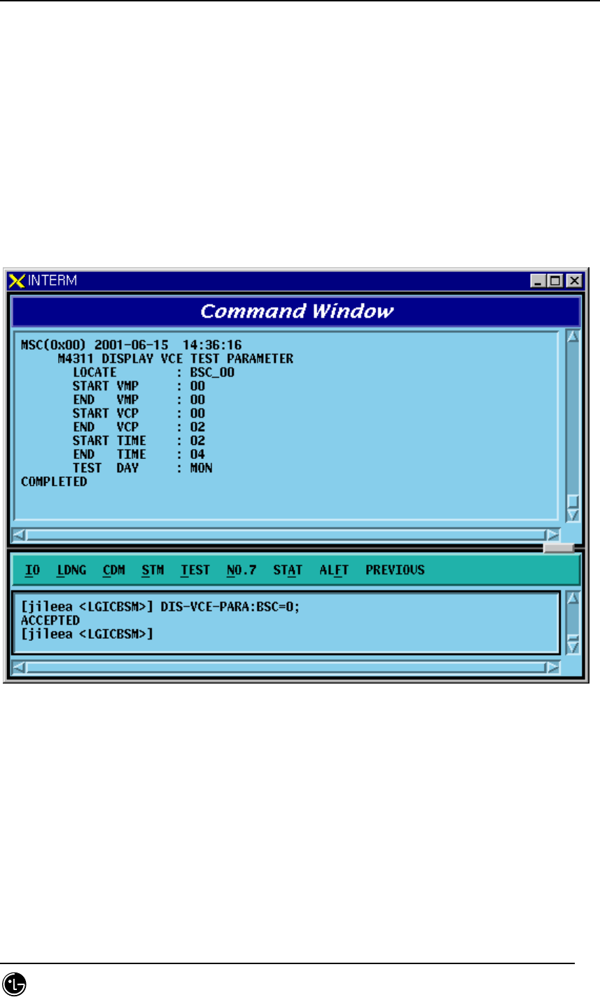
4.5.3.3. Parameter Display Command related to On-Line Vocoder Test
Function to display On-Line Vocoder test start/ending time, test day, and the scope of
VMP/VCPto be tested.
• Command DIS-VCE-PARA:BSC=a;
a: BSC number (0~11)
• Input/Output
Fig. 4.5-9 Result of On-Line Vocoder Test Parameter Display Command Execution
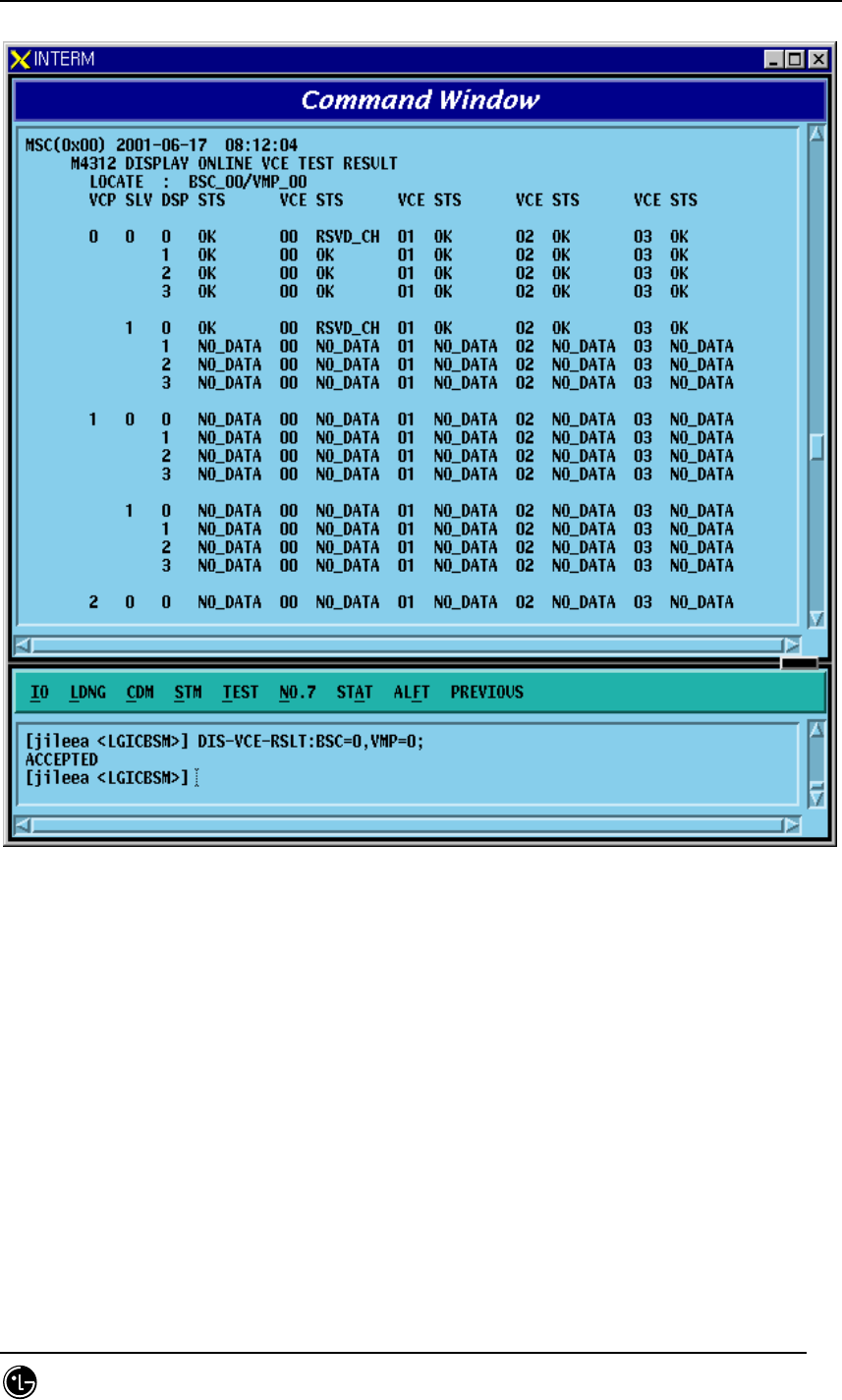
4.5.3.4. Display Command of On-Line Vocoder Test Result
Function to display the On-Line Vocoder Test Results which are stored in CCP to BSM
by the VMP unit
• Command DIS-VCE-RSLT:BSC=a,VMP=b;
a: BSC number (0~11)
b: VMP number (0~7)
STAREX-IS BSM Manual
Page:432(877)
Issue:1.
0
SMD-011-PMA210
• Input/Output
Fig. 4.5-10 On-Line Vocoder Test Result Display Command
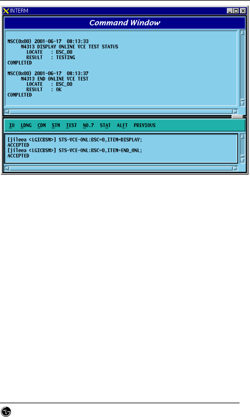
4.5.3.5. Display Command of On-Line Vocoder Test Status
Function to display the On-Line Vocoder Test performance status and to stop the test.
If Item Field is designated as “DISPLAY”, it displays On-Line Vocoder test status of
the present corresponding BSC, and if it is designated as "END_ONL", it stops current
On-Line test.
• Command STS-VCE-ONL:BSC=a,ITEM=b;
a: BSC number (0~11)
b: Execution ITEM (DISPLAY/END-ONL)
• Input/Output
STAREX-IS BSM Manual
Page:433(877)
Issue:1.
0
SMD-011-PMA210
Fig. 4.5-11 On-Line Vocoder Test End Command, Status Display Command Execution Result

STAREX-IS BSM Manual
Page:434(877)
Issue:1.
0
SMD-011-PMA210
4.5.4. Link Test Function
Link test is divided into PING test, IPC test, ATM Path test, and Trunk BER test. PING
test checks the Link status of Application Level by using Ping command from Master
Processor to each Target Processor. IPC test checks the presence of problems in
LINK by conducting IPC Test to the mounted processors/devices. ATM Path test
checks presence of faults in ATM LINK Level by conducting ATM Layer Test on the
mounted Processor/Devices. Trunk BER test sends/receives the designated number of
ATM Cells to the operator designated BTS Link to get Error Rate.
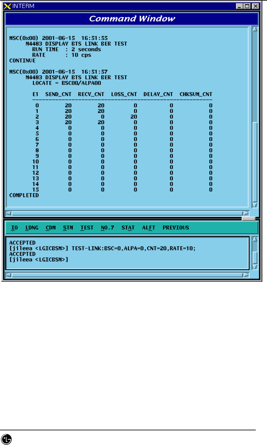
4.5.4.1. Trunk BER Test Function
Function to check the presence of problems in Trunk(16 E1) Link between BTS and
BSC. Trunk BER Test analyzes performance per Link of each ALPA and LICA and the
analyzed result is displayed in a certain format to BMS. One link is selected and while
exchanging as many as the designated number of ATM Cells, test is conducted and
Data Error Rate is displayed.
• Command TEST-LINK :BSC=a ,ALPA=b [,CNT=c] [,RATE=d];
a: BSC number (0~11)
b: ALPA number(0~9)
c: Send Cell Count(1 ~ 1,000,000)
d: Data Rate(1 ~ 90: Number of Cells transferred per a second)
• Input/Output
STAREX-IS BSM Manual
Page:435(877)
Issue:1.
0
SMD-011-PMA210
Fig. 4.5-12 Result of Trunk BER Test Performance
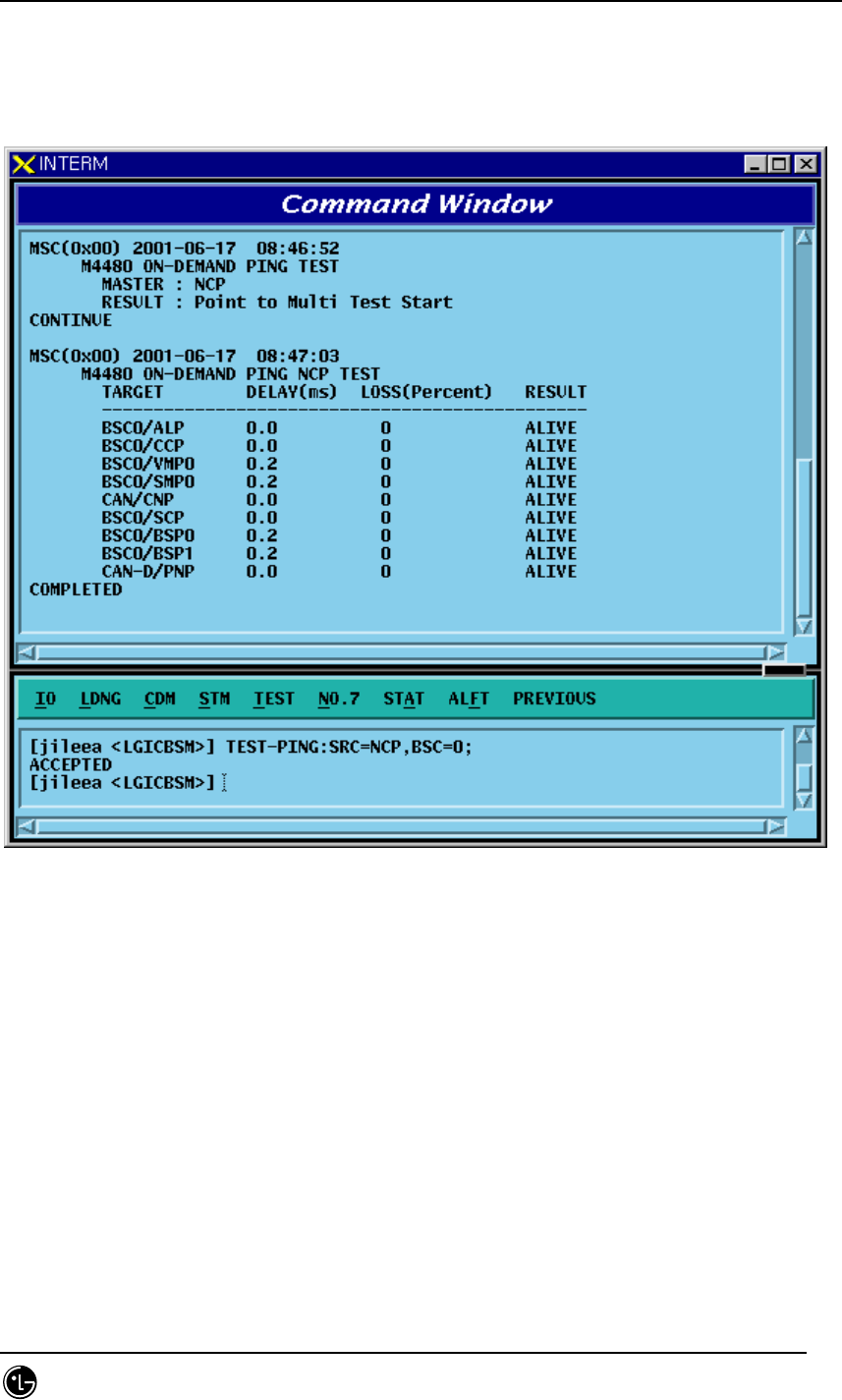
4.5.4.2. PING Test Function
Function to check Link Status for the Target Processor by the Master Processor that
was input to MMI of BSM by using the Ping command
Ping test is divided into Point To Point Test and Point To Multi Test.
• Command TEST-PING:SRC=a,DST=b[,BSC=c][,BTS=d][,SMP=e][,VMP=f][,PCF=g];
a: Source Processor
b: Destination Processor(If there is input, it is PTP, if not, it is PTM)
c: BSC number(0~11)
d: BTS number(0~47)
STAREX-IS BSM Manual
Page:436(877)
Issue:1.
0
SMD-011-PMA210
e: SMP number(0~5)
f: VMP number(0~7)
g: PCF number(0~2)
• Input/Output
Fig. 4.5-13 Result of PING Test Performance
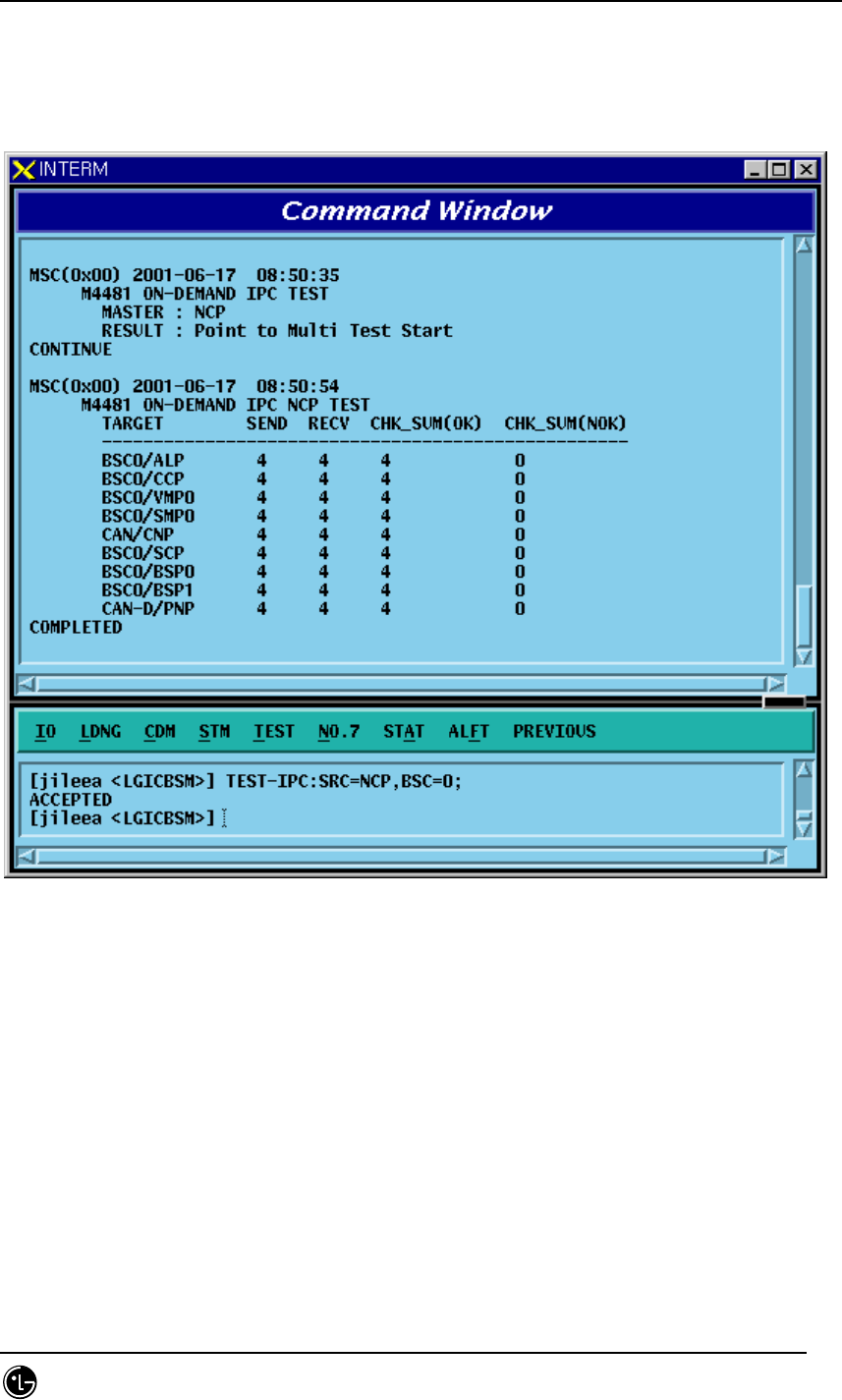
4.5.4.3. IPC Test Function
Function to check the presence of problems in the Link status between
Processor/Device by executing IPC command of Application Level .
IPC Test is divided into PTP test and PTM test.
• Command TEST-IPC :SRC=a [,DST=b] [,BSC=c] [,BTS=d] [,SMP=e] [,VMP=f]
[,PCF=g];
a: Source Processor
b: Destination Processor(If input does exist, it is PTP and if not, it is PTM)
c: BSC number(0~11)
d: BTS number(0~47)
STAREX-IS BSM Manual
Page:437(877)
Issue:1.
0
SMD-011-PMA210
e: SMP number(0~5)
f: VMP number(0~7)
g: PCF number(0~2)
• Input/Output
Fig. 4.5-14 Result of IPC Test Performance
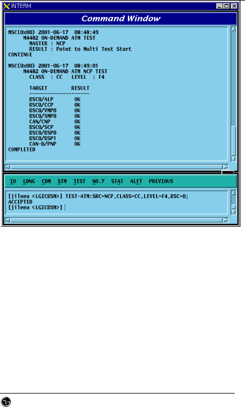
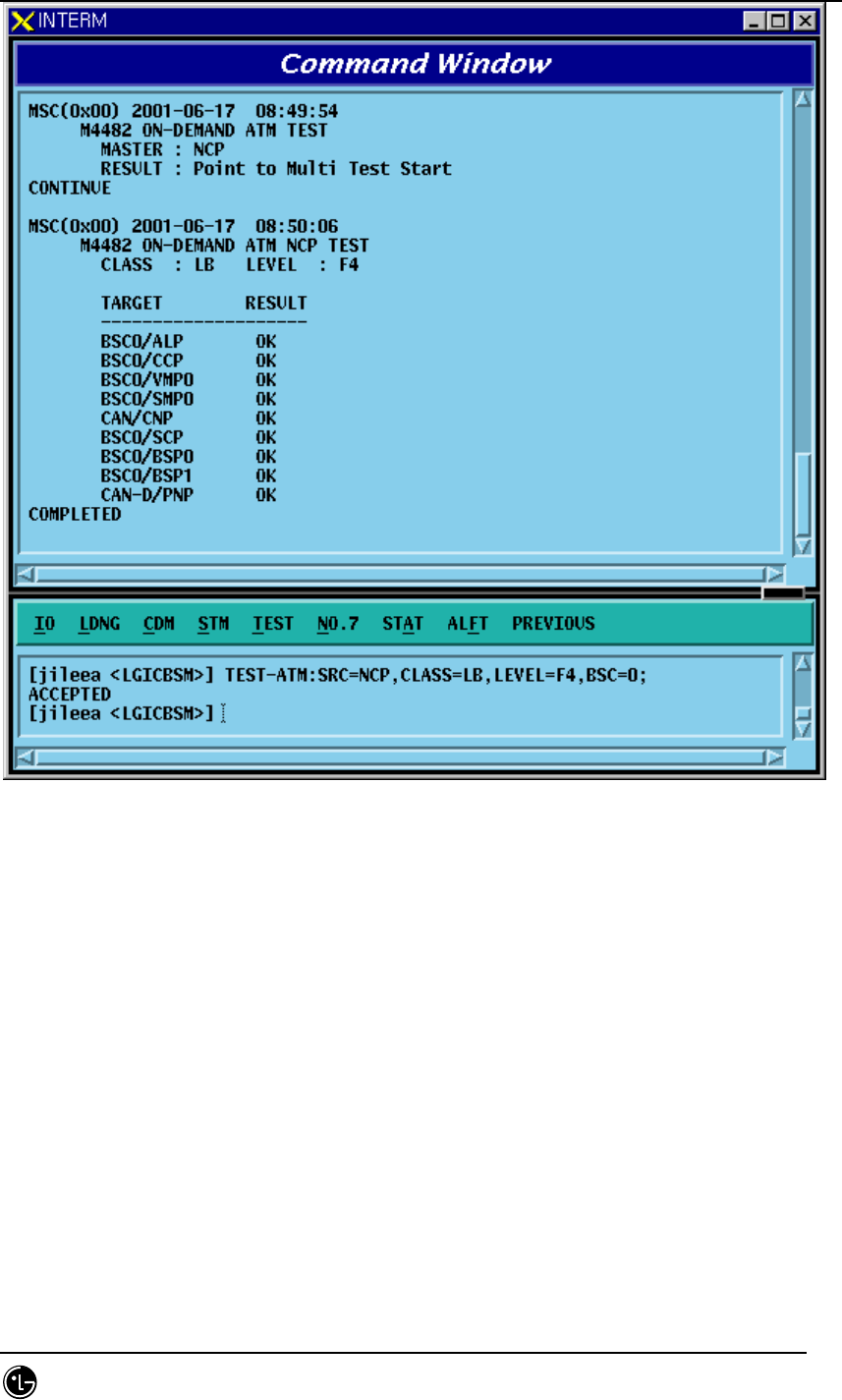
4.5.4.4. ATM Path Test Function
Function to check presence of problems in Link Status between Processor and Device
by executing ATM CC, LB, PM command.
It is divided into PTP Test and PTM Test.
• Command TEST-
TM:SRC=a[,DST=b],CLASS=c,LEVEL=d[,BSC=e][,BTS=f][,SMP=g] [,VMP=h] [,PCF=i];
a: Source Processor
b: Destination Processor(If input does exist, it is PTP, and if not, it is PTM)
c: Test class(CC: Continuity Check, LB: Loop Back, PM: Execution Monitor)
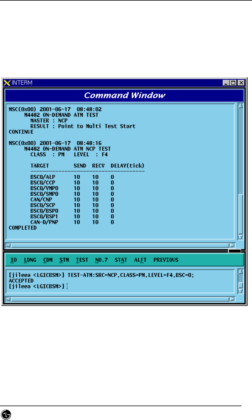
STAREX-IS BSM Manual
Page:438(877)
Issue:1.
0
SMD-011-PMA210
d: Test Level(F4: VPC, F5: VCC)
e: BSC number(0~11)
f: BTS number(0~47)
g: SMP number(0~5)
h: VMP number(0~7)
i: PCF number(0~2)
• Input/Output
Fig. 4.5-15 Result of ATM Path(PM) Test Performance
STAREX-IS BSM Manual
Page:439(877)
Issue:1.
0
SMD-011-PMA210
Fig. 4.5-16 Result of ATM Path(CC) Test Performance
STAREX-IS BSM Manual
Page:440(877)
Issue:1.
0
SMD-011-PMA210
Fig. 4.5-17 Result of ATM Path(LB) Test Execution

STAREX-IS BSM Manual
Page:441(877)
Issue:1.
0
SMD-011-PMA210
4.5.5. Command related to BSC Virtual Call Test
General mobile call is ㅡmade by MS, BSS(BSC, BTS), switching system interworking.
Because the section between MS and BSS is the place where call environment setup
function and modulation and demodulation of voice data are made including allocation
of call resource necessary for radio communication, it is responsible for essential
function in the mobile communication system. Testing call is the function to check the
following: 1) the presence of faults in call processing made between BSS and MS that
excludes the MSC function in the course of mobile call processing, and 2) the quality
of voice. Since it excludes the MS function to, mutual calls such as M2L, L2M, or M2M
cannot be made; however, , but cantest can be perfomed by selecting one between
originating and terminating call. When a testing call was set up, BSS and MS generate
markov data and exchange them and by checking if there is any loss of markov data,
they calculate quality of voice. Terminating call inputs IMSI value of MS to be tested in
BSM and trys paging to set up a call. And Originating call sets up a call by selecting
testing call function of MS. (Originating call is not related to BSM function.)
• BSC Testing Call
It checks the following: 1) if there is any faults in call processing that is carried out
between BSC(SLP) – BTS(CE) - MSs and 2) the quality of voice. If a Call is attempted
in BSM by inputting the the information (i.e., the number of MS, BSC number, BTS
number, sector, frequency resource, MS call setup data (Station Class Mark, Slot Cycle
Index), Service Option(13K Markov, 8K Markov, 13K LoopBack, 8K LoopBack), and
voice packet data rate(Full, half, Quarter, Eighth , Variable rate)), then Call Link
between SLP-CE-MS is set up (setup of testing call) according to the data input. Once
a Call is set up, SLP and MS calculate Frame Error Rate while exchanging markov data.
When a Call is set up and a Call is released, BSM displays data of call resource, FER,
and reason for release.
• Service Option
Service Options of present use for Testing call at BSC include 8K Markov, 13K Markov,
8K loopback, 13K loopback .
• Markov
Once Testing Call is set up, SLP and MS synchronizes their time, and generate
identical data in sequence by Markov Algorithm. SLP and MS receive each other’s data
and compare them with their own to detect errors in the data frame. It can obtain
Forward FER(measured at MS) and Reverse FER(measured at SLP).
LoopBack: When Testing Call is set up, SLP generates voice data and sends them to
MS. MS performs lookback on this data as it is and SLP compares returned data with

STAREX-IS BSM Manual
Page:442(877)
Issue:1.
0
SMD-011-PMA210
the original data to validate the quality of voice. (FER measured at SLP)
• Data Rate
User can designate voice data rate to be used for testing call. The data rate is divided
into the following: Full rate, Half rate, Quarter rate, Eighth rate, and Variable rate.
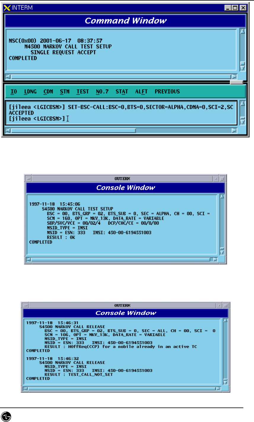
4.5.5.1. BSC Virtual Call Setup Function
Function to designate various options and setting up Call to a specific MS or all the
MSs MS to be tested should be entered to BSM DB with INS-TEST-MS command.
When TEST_KEY is not input, testing calls are set up for all the MSs stored in DB.
Testing Call is attempted for 60 minutes at a maximum. Once a Call is set up, it is
maintained for 60 minutes. If a call is disconnected due to the occurrence of faults, or
when a user released the call at random, a message for the reason of call release is
displayed.
• Command SET-TEST-CALL :BSC=a ,BTS=b ,SECTOR=c ,CDMA=d ,SCI=e ,SCM=f ,
OPTI=g ,DTYPE=h ,TIME=i [,TEST_KEY=j];
a: BSC number (0~11)
b: BTS number (0~47)
c: sector (ALPHA/BETA/GAMMA/DELTA/ZETA/EPSILON)
d: CDMA number (0~11)
e: SLOT CYCLE Index (0~7)
f: SLOT mode (SLOT_M, NON_SLT_M)
g: option (MKV_13K/MKV_8K/LB_13K/LB_8K)
h: Data Rate (VARIABLE/FULL/HALF/QUART/EIGHT )
i: TIME(1~60min)
j: Test Key(1 ~ 100)
• Input/Output
STAREX-IS BSM Manual
Page:443(877)
Issue:1.
0
SMD-011-PMA210
Fig. 4.5-18 BSC Virtual Call Setup Command INTERM Display
Fig. 4.5-19 Console Window Display at the setup of BSC Virtual Call
STAREX-IS BSM Manual
Page:444(877)
Issue:1.
0
SMD-011-PMA210
Fig. 4.5-20 Display at the Termination of BSC Virtual Call
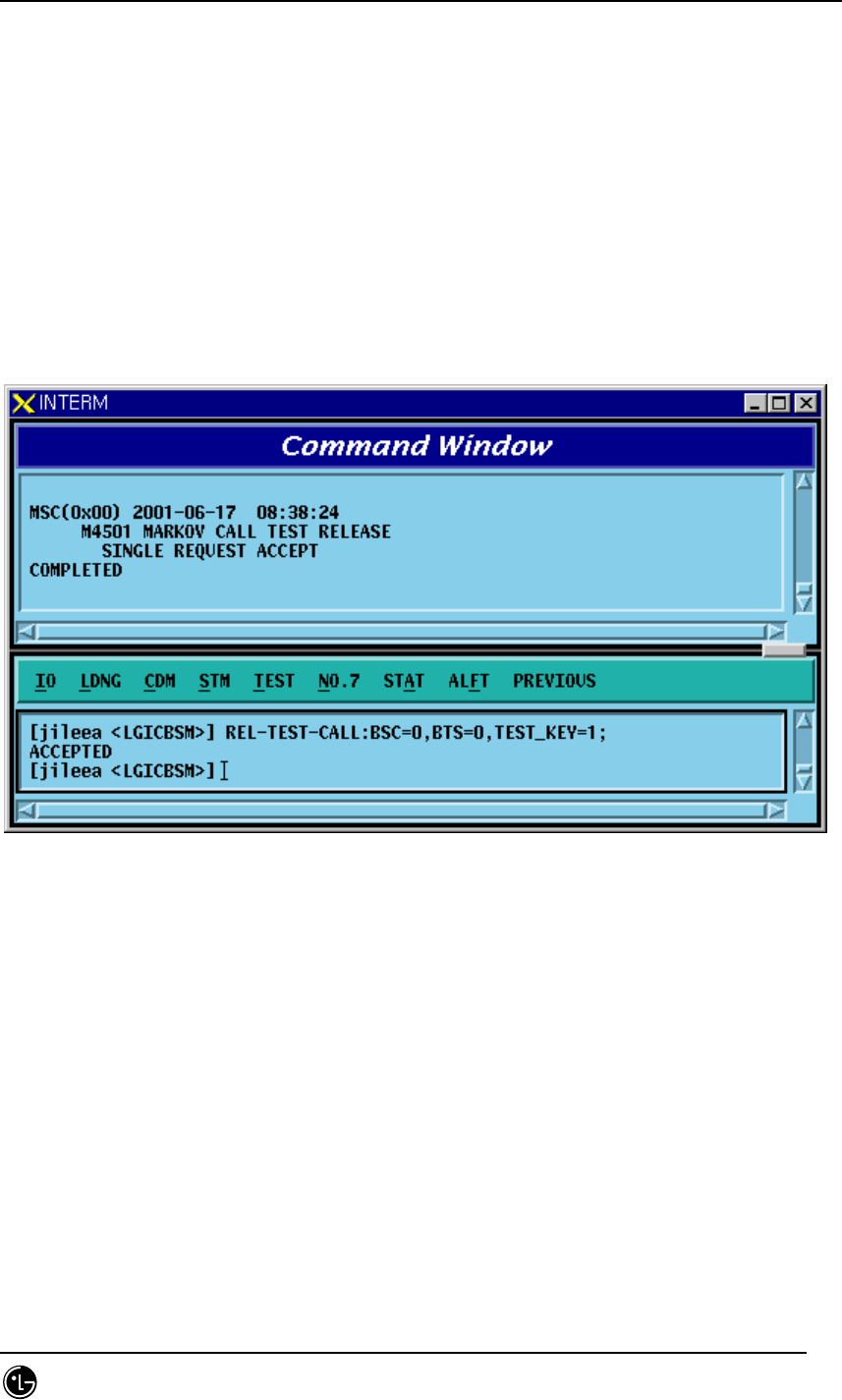
4.5.5.2. Virtual Call Release Function
Function to release a call for a specific MS or all the MSs where a virtual call set up.
The output resulting from virtual call release is displayed by "Release by MMC".
• Command REL-TEST-CALL :BSC=a ,BTS=b [,TEST_KEY=c];
a: BSC number (0~11)
b: BTS number (0~15)
c: TEST KEY(1~100)
• Input/Output
Fig. 4.5-21 Result of BSC Virtual Call Release Command Execution
4.5.5.3. Testing MS Display Function
Function to display MSs to be used for the BSC Virtual Call test.
• Command DIS-TEST-MS :BSC=a ,BTS=b;
a: BSC number (0~11)
b: BTS number (0~47)
• Input/Output
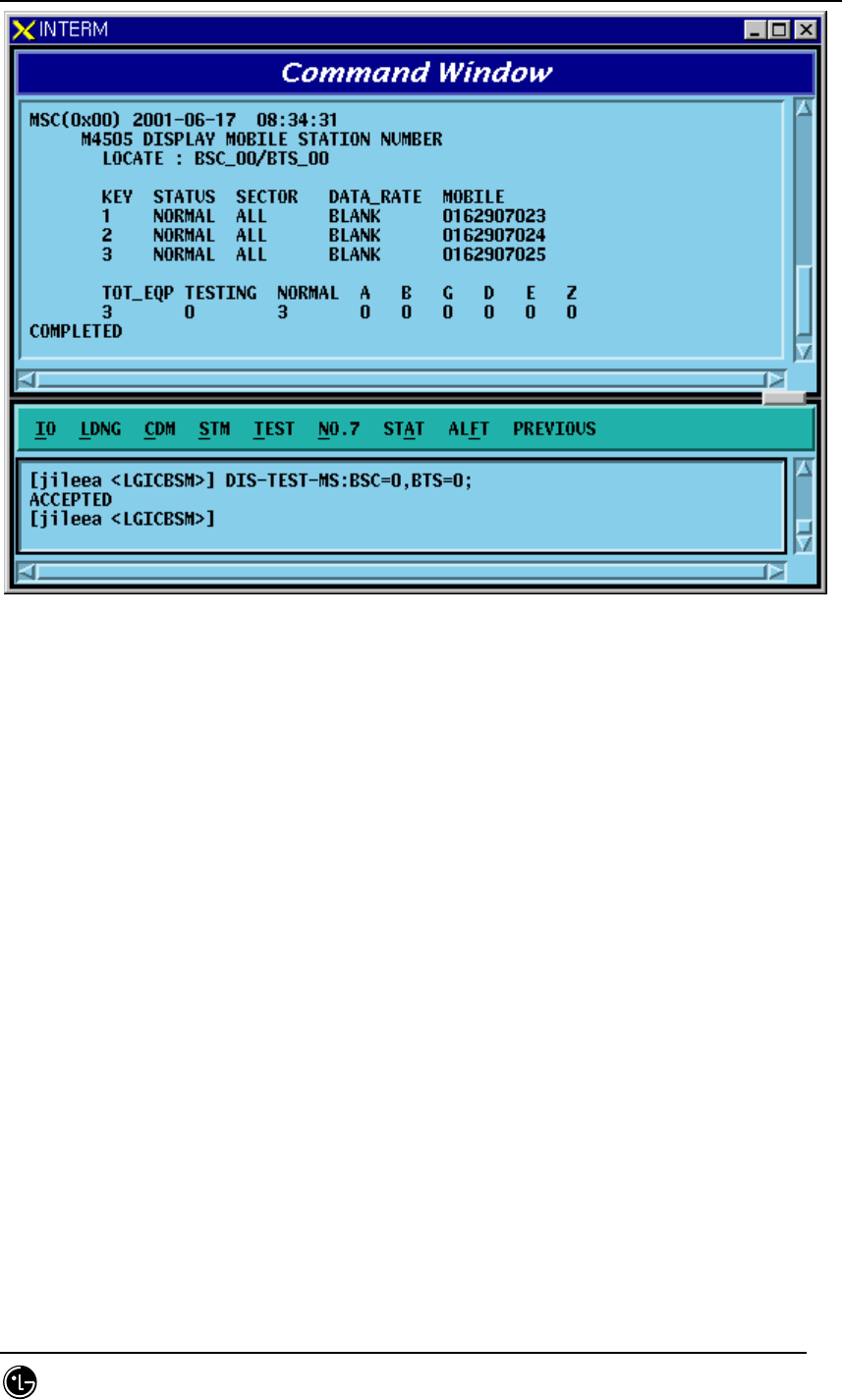
STAREX-IS BSM Manual
Page:445(877)
Issue:1.
0
SMD-011-PMA210
Fig. 4.5-22 Presently registered Testing MS Display
4.5.5.4. MS Supplementary Function
Function to register MS to be used for the BSC Virtual test.
For a test of virtual call, first register MS.
• Command INS-TEST-MS :BSC=a ,BTS=b ,TEST_KEY=c [,MSIN=d];
a: BSC number (0~11)
b: BTS number (0~47)
c: TEST KEY(1~100)
d: IMSI of MS
• Input/Output
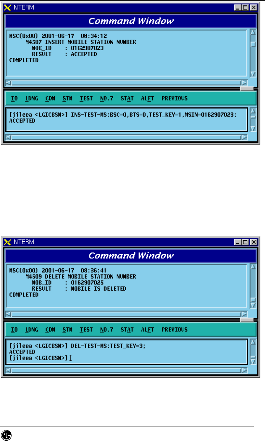
STAREX-IS BSM Manual
Page:446(877)
Issue:1.
0
SMD-011-PMA210
Fig. 4.5-23 Testing MS Insert Result Display
4.5.5.5. MS Delete Function
Function to delete MS registered on the test list of BSC Virtual Call
• Command DEL-TEST-MS :TEST_KEY=a;
a: TEST_KEY of Mobile to be deleted
• Insert/Output
Fig. 4.5-24 Delete MS Execution Result

STAREX-IS BSM Manual
Page:447(877)
Issue:1.
0
SMD-011-PMA210
4.5.6. TRAFFIC PATH TESTING FUNCTION
it is a test enabling to decide if there is presence of failure with designated traffic
path by setting a traffic path for BSC virtual call for a specific MS with the designated
call resources and then measuring PER.. The kinds of virtual call include Markov and
Loop Back., There are 8K and 13K respectively by service option. Call resources that
the user can designate are as follows: Selector Slave Processor, Trunk, and BTS
channel Chip. In one BSC, 100 virtual calls can be set up simultaneously separated
from testing function of virtual call. Once a call is set up, a message type which is
identical to the message type coming from BSC virtual call setup process is displayed.
4.5.6.1. Traffic Path Testing Setup Function
Function to set up a Call for the designated Traffic Path
• Command SET-PATH-CALL : IMSI=a , BSC=b , SMP=c , SLP=d , SLPSLV = e [,TRK =
f], BTS= g ,SECTOR = h ,CDMA = i ,RCP= j , MCPA=k , CHIP=l , SCI=m , SCM=n ,
OPTI=o , DTYPE=p [,TIME=q];
a : IMSI
b : BSC_Number(0~11)
c : SMP_Number(0~4)
d : SLP_Number(0~19)
e : SLP_Slave_Number(0~3)
f : Trunk_Number(0~19)
g : BTS_Number(0~47)
h : Sector_Id(0~5)
i : CDMA_Channel_Number(0~11)
j : RCP_Number(0~9)
k : MCPA_Number(0~9)
l : CHIP_Number(0~1)
m : Slot_Cycle_Index(0~7)
n : Station_Class_Mark(SLOT_M, NON_SLT_M)
o : Service_Option(MKV_13K, MKV_8K, LB_13k, LB_8K)
p : Test_data_Type(VARIABLE, RATE_FULL, RATE_HALF, RATE_QUAR, RATE_EIGHT)
q : TRACE_TIME(1~60min)
• Input/Output
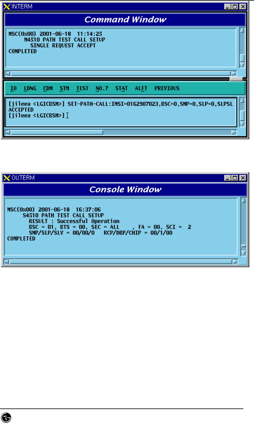
STAREX-IS BSM Manual
Page:448(877)
Issue:1.
0
SMD-011-PMA210
Fig. 4.5-25 Traffic Path Setup Command Execution Result Display(Interm Window)
Fig. 4.5-26 Traffic Path Setup Command Execution Result Display(Console Window)
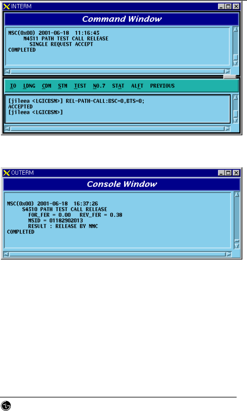
4.5.6.2. Traffic Path Release Function
Function to release a Call to MS of a specific BSC, BTS where a virtual call is set up.
• Command REL-PATH-CALL :BSC=a ,BTS=b;
a: BSC number (0~11)
b: BTS number (0~15)
• Input/Output
STAREX-IS BSM Manual
Page:449(877)
Issue:1.
0
SMD-011-PMA210
Fig. 4.5-27 Traffic Path Release Command Execution Result Display(Interm Window)
Fig. 4.5-28 Traffic Path Release Command Execution Result Display(Console Window)