LG Electronics USA 3G1XINBTS STAREX-IS 1900 Indoor BTS User Manual STAREX IS User s Manual
LG Electronics USA STAREX-IS 1900 Indoor BTS STAREX IS User s Manual
Contents
Users Manual Part A

STAREX-BSS IS2000
BSM User’s Manual
( STAREX-IS User’s Manual )

STAREX-IS BSM Manual
Page:1(877)
Issue:1.
0
SMD-011-PMA210
This equipment has been tested and found to comply with the limits for a Class A
digital device, pursuant to part 15 of the FCC Rules.
These limits are designated to provide reasonable protection against harmful
interference when the equipment is operated in a commercial environment. This
equipment generates, uses, and can radiate radio frequency energy and, if not installed
and used in accordance with the instruction manual, may cause harmful interference to
radio communications.
Operation of this equipment in a residential area is likely to cause harmful interference
in which case the user will be required to correct the interference at his own expense.
CAUTION :
Do not attempt to modify this product in any way without written authorization from
LG Electronics Inc.
Unauthorized modification could void the user's authority to operate this product.
The responsible party for this device compliance is :
Company Name : LGInfoComm U.S.A. Inc.
Address : 10225 Willow Creek RD San Diego, CA, 92131, U.S.A.
Telephone No. : 858-635-5332

STAREX-IS BSM Manual
Page:2(877)
Issue:1.
0
SMD-011-PMA210
Contents
1. Introduction to BSM ................................................................................................. 36
1.1. Overview........................................................................................................... 36
1.1.1. Configuration Management of System.....................................................................36
1.1.2. Fault Management of System...................................................................................36
1.1.3. Performance Management of System......................................................................38
1.1.4. Security Management of System .............................................................................39
1.1.5. Account Management of System .............................................................................39
1.2. Interoperability and Operation .......................................................................... 39
1.2.1. Configuration Management of System.....................................................................40
1.2.2. Fault Management of System...................................................................................40
1.2.3. Performance Management of System......................................................................40
1.2.4. Security Management of System .............................................................................41
1.2.5. Account Management of System .............................................................................42
1.3. BSM Configuration............................................................................................ 42
1.3.1. S/W System Boundary..............................................................................................42
1.3.2. S/W Architecture......................................................................................................43
2. BSM Environment Setting ........................................................................................ 45
2.1. OS Installation................................................................................................... 45
2.1.1. Solaris 2.7 Installation Procedures..........................................................................45
2.1.2. Network Environment Setting Procedures..............................................................63
2.2. DBMS(Informix) Installation.............................................................................. 66
2.2.1. Informix Install .........................................................................................................66
2.2.2. Environment Setting.................................................................................................75
2.2.3. Execution..................................................................................................................81
2.2.4. Others .......................................................................................................................82
2.3. ATM Adaptor Setup .......................................................................................... 85
2.3.1. SunATM Adopter Setup .........................................................................................85
2.3.2. SunATM S/W Installation and Solaris Setup File Modification ...............................85
2.3.3. SunATM IPoA Driver Load ......................................................................................91
2.3.4. System File Changed by atm_setup Tool ................................................................92
2.4. User Environment ........................................................................................... 129
3. BSM Package Configuration................................................................................... 129
3.1. Application Configuration................................................................................ 129
4. BSM Command ....................................................................................................... 132
4.1. User Interface Command ................................................................................ 132

STAREX-IS BSM Manual
Page:3(877)
Issue:1.
0
SMD-011-PMA210
4.1.1. User Management Command .................................................................................132
4.1.2. Command Management Command .........................................................................139
4.1.3. History Management Command .............................................................................143
4.2. Loading Command........................................................................................... 148
4.2.1. Loading Control Command.....................................................................................148
4.2.2. Loading Information Display Command .................................................................154
4.3. Configuration Command.................................................................................. 163
4.3.1. Parameter Information Display Command (Display_Parameter_Information_1) ..163
4.3.2. Parameter Information Display (Display_Parameter_Information_2)....................192
4.3.3. NETWORK Information Display (Display_Parameter_Information_3) ..................213
4.3.4. Parameter Information Change Command (Change_Parameter_Information_1) ..250
4.3.5. Parameter Information Change Command (Change_Parameter_Information_2) ..288
4.3.6. Network Parameter Information Change (Change_Parameter_Info_3).................318
4.3.7. Configuration Information Display(Display_Configuration_Data)..........................329
4.3.8. Configuration Information Change (Change_Configuration_Data) ........................337
4.4. STATUS COMMAND ...................................................................................... 380
4.4.1 PROCESSOR STATUS CONTROL ..........................................................................380
4.4.2. Network Status Control .........................................................................................385
4.4.3. Can Device Status Control .....................................................................................390
4.4.4. BSC Device Status Control ....................................................................................394
4.4.5. Bts Device Status Control......................................................................................403
4.4.6. Status Message Control .........................................................................................411
4.4.7. Overload Status Control.........................................................................................414
4.5. Test Command ................................................................................................ 420
4.5.1. On-Line Test-related Command ...........................................................................420
4.5.2. Test-related to Channel Element..........................................................................424
4.5.3. Vocoder Test Function ..........................................................................................426
4.5.4. Link Test Function .................................................................................................434
4.5.5. Command related to BSC Virtual Call Test...........................................................441
4.5.6. TRAFFIC PATH TESTING FUNCTION.................................................................447
4.5.7. Call Trace Testing Function ..................................................................................450
4.5.8. Number of Data Call User Display Function (Active/Dormant) ............................456
4.5.9. DATA Call User Status Display Function by IMSI ................................................457
4.5.10. IOS Message Display Function ............................................................................458
4.5.11. POWER MONITORING Function ..........................................................................461
4.6. No.7 Command................................................................................................ 463
4.6.1. Related Command...................................................................................................463

STAREX-IS BSM Manual
Page:4(877)
Issue:1.
0
SMD-011-PMA210
4.6.2. Signaling Link Operation Management Function ...................................................465
4.6.3. Maintenance Function Command ...........................................................................486
4.7. Statistics Command......................................................................................... 491
4.7.1. Traffic related Statistics Command .......................................................................493
4.7.2. Handoff Related Statistics Function ......................................................................497
4.7.3. Call Related Statistics Function .............................................................................503
4.7.4. Packet Related........................................................................................................515
4.7.5. Other Statistics Related Commands ......................................................................518
4.8. Alarm/Fault Command..................................................................................... 521
4.8.1. Alarm/Fault Display................................................................................................523
4.8.2. Alarm/Fault Inhibition.............................................................................................529
4.8.3. Alarm/Fault Control................................................................................................533
4.8.4. Environment Alarm Control ...................................................................................536
4.9. Operation through GUI.................................................................................... 546
4.9.1. Manager Window....................................................................................................546
4.9.2. Interm Window .......................................................................................................546
4.9.3. Batch Job ................................................................................................................550
4.9.4. Console Window .....................................................................................................558
4.9.5. Controller ...............................................................................................................559
4.9.6. Status Window (stmGUI) ........................................................................................561
4.9.7. Neighbor Control Window (neighbor)....................................................................576
4.9.8. Call Trace Window.................................................................................................583
4.9.9. BTS Address Search Window. ...............................................................................594
5. BSM On-Line Message .......................................................................................... 601
5.1. Fault/Alarm Message ...................................................................................... 601
5.1.1. Alarm Message.......................................................................................................601
5.1.2. Fault Message ........................................................................................................689
5.2. Status Command ............................................................................................. 717
5.2.1. Processor Status Change Report ...........................................................................717
5.2.2. Overload Status Change Report Function .............................................................724
5.3. Loading Message ............................................................................................ 726
5.3.1. Processor Initialization Start Message ..................................................................726
5.3.2. Processor Initialization End Message....................................................................726
5.3.3. Loading Start Message...........................................................................................727
5.3.4. Loading Completion Message ................................................................................728
5.3.5. Loading Failure Message .......................................................................................729
5.3.6. Firmware Update Report Message ........................................................................729

STAREX-IS BSM Manual
Page:5(877)
Issue:1.
0
SMD-011-PMA210
6. Trouble Shoot ........................................................................................................ 730
6.1. If BSM is not operated .................................................................................... 730
6.1.1. If BSM is not initialized ..........................................................................................730
6.1.2. It can not function normally despite of its initialization ........................................732
6.2. If Graphic Application is not run ..................................................................... 732
6.2.1. Environment Variables...........................................................................................733
6.2.2. If Manager in Remote Area is not operated ..........................................................734
7. CHG- Appendix ..................................................................................................... 736
7.1. Alarm/Fault Message Description and List..................................................... 736
7.1.1. Alarm Message Description and List.....................................................................736
7.1.2. Fault Message Description and List ......................................................................743
7.1.3. Measures for Alarm Message ................................................................................744
7.1.4. Measures for Fault Message..................................................................................762
7.2. Status Message Description and LIST Status Definition and LIST................. 766
7.3. DCI Debugger Command................................................................................. 769
7.3.1. Tx/Rx Message Trace Function ............................................................................769
7.3.2. Function to test Function .......................................................................................773
7.3.3. Status Display Funciton .........................................................................................775
7.3.4. Other Supplementary Function ..............................................................................779
7.4. Statistic Message............................................................................................ 781
7.4.1. Traffic Related .......................................................................................................781
7.4.2. Handoff Statistic Function......................................................................................784
7.4.3. Call Related Statistic Function...............................................................................785
7.4.4. Packet .....................................................................................................................790
7.5. PLD Data Structure......................................................................................... 793
7.5.1. BSM layer ...............................................................................................................793
7.5.2. CNP ONLY..............................................................................................................793
7.5.3. PNP ONLY ..............................................................................................................798
7.5.4. PCP ONLY ..............................................................................................................804
7.5.5. CCP ONLY ..............................................................................................................807
7.5.6. NCP ONLY..............................................................................................................824
7.5.7. SCP ONLY ..............................................................................................................839
7.5.8. CCP/BSP COMMON................................................................................................842
7.5.9. BSP Layer...............................................................................................................857
7.6. Abbreviations.................................................................................................. 877

STAREX-IS BSM Manual
Page:6(877)
Issue:1.
0
SMD-011-PMA210
Figures
FIG. 1.3-1 BSM S/W CONFIGURATION ......................................................................... 44
FIG. 2.1-1 OS LANGUAGE SELECTION SCREEN.......................................................... 45
FIG. 2.1-2 OS INSTALLATION LANGUAGE AND SELECTION SCREEN 2................... 46
FIG. 2.1-3 OS INSTALLATION TIME SETTING ............................................................ 46
FIG. 2.1-4 HOST NAME INPUT SCREEN .................................................................... 47
FIG. 2.1-5 HOST NAME INPUT 2 .................................................................................. 47
FIG. 2.1-6 NETWORK SETTING SCREEN ..................................................................... 48
FIG. 2.1-7 IP ADDRESS INPUT SCREEN....................................................................... 48
FIG. 2.1-8 IP ADDRESS INPUT SCREEN 2.................................................................... 49
FIG. 2.1-9 NETWORK BASIC SETTING SUMMARY SCREEN ....................................... 49
FIG. 2.1-10 DNS SETTING SCREEN.............................................................................. 50
FIG. 2.1-11 DNS SETTING SCREEN 2........................................................................... 50
FIG. 2.1-12 DNS SETTING SUMMARY SCREEN ........................................................... 51
FIG. 2.1-13 SUBNET SETTING SCREEN .................................................................... 51
FIG. 2.1-14 SUBNET SETTING SCREEN 2 ................................................................... 51
FIG. 2.1-15 SUBNET SETTING SCREEN 3 ................................................................... 52
FIG. 2.1-16 OS TIME SETTING METHOD SCREEN ...................................................... 52
FIG. 2.1-17 OS TIME SETTING REGION SELECTION SCREEN ................................... 53
FIG. 2.1-18 OS TIME SETTING REGION SELECTION SCREEN 2 ................................ 53
FIG. 2.1-19 TIME SETTING SCREEN ............................................................................ 54
FIG. 2.1-20 SUBNET AND TIME SETTING SUMMARY SCREEN ................................. 54
FIG. 2.1-21 OS INSTALLATION METHOD SELECTION SCREEN................................. 54
FIG. 2.1-22 ATTENTION TO THE INSTALLATION OF OS .......................................... 55
FIG. 2.1-23 X-TERMINAL SETTING SCREEN .............................................................. 55
FIG. 2.1-24 USER LANGUAGE SELECTION SCREEN ................................................... 56
FIG. 2.1-25 OS INSTALLATION CATEGORY SELECTION SCREEN............................. 56
FIG. 2.1-26 OS INSTALLATION CATEGORY SELECTION SCREEN 2.......................... 57
FIG. 2.1-27 OS INSTALLATION DISK SELECTION SCREEN........................................ 57
FIG. 2.1-28 WARNING SENTENCE SCREEN RESULTING FROM THE DISK SETTING58
FIG. 2.1-29 SELECTION SCREEN FOR DISK INSTALLATION METHOD ..................... 58
FIG. 2.1-30 SELECT SCREEN FOR DISK INSTALLATION METHOD ........................... 58
FIG. 2.1-31 SELECTED DISK INFORMATION DISPLAY SCREEN................................. 59
FIG. 2.1-32 AREA INFORMATION DISPLAY SCREEN FOR THE DISK DIVISION......... 60
FIG. 2.1-33 DISK ALLOCATION RESULT DISPLAY SCREEN ....................................... 61

STAREX-IS BSM Manual
Page:7(877)
Issue:1.
0
SMD-011-PMA210
FIG. 2.1-34 REMOTE FILE SERVER INSTALLATION SCREEN .................................... 62
FIG. 2.1-35 SET UP INFORMATION DISPLAY SCREEN FOR THE INSTALLATION.... 62
FIG. 4.1-1 BSM SYSTEM LOGIN WINDOW.................................................................. 132
FIG. 4.1-2 LOG-OUT.................................................................................................... 133
FIG. 4.1-3 USER ID REGISTER .................................................................................... 134
FIG. 4.1-4 ERRORS WHEN REGISTERING USER ID.................................................. 134
FIG. 4.1-5 USER ID DELETION ................................................................................. 135
FIG. 4.1-6 ERRORS WHEN DELETING USER ID THAT DOES NOT EXIST ................ 135
FIG. 4.1-7 ERRORS WHEN DELETING THE MANAGER CLASS ID............................. 136
FIG. 4.1-8 USER CLASS CHANGE ............................................................................... 137
FIG. 4.1-9 ERRORS WHEN CHANGING THE USE CLASS OF THE MANAGER .......... 137
FIG. 4.1-10 USER INFORMATION DISPLAY................................................................ 138
FIG. 4.1-11 USER PASSWORD CHANGE ..................................................................... 139
FIG. 4.1-12 COMMAND CLASS MODIFICATION....................................................... 140
FIG. 4.1-13 COMMAND CLASS DISPLAY.................................................................. 141
FIG. 4.1-14 COMMAND INFORMATION DISPLAY BY NAME ..................................... 142
FIG. 4.1-15 COMMAND INFORMATION DISPLAY BY CRN ........................................ 143
FIG. 4.1-16 COMMAND HISTORY DISPLAY................................................................ 144
FIG. 4.1-17 MESSAGE HISTORY DISPLAY START..................................................... 146
FIG. 4.1-18 MESSAGE HISTORY DISPLAY END ....................................................... 147
FIG. 4.2-1 BLOCKING LOADING PERFORMANCE RESULT ....................................... 149
FIG. 4.2-2 ACTIVATION LOADING PERFORMANCE RESULT ................................... 150
FIG. 4.2-3 FLASH MEMORY UPDATE RESULT .......................................................... 151
FIG. 4.2-4 LOADING INFORMATION DISPLAY COMMAND EXECUTION RESULT . 155
FIG. 4.2-5 LOADING HISTORY DISPLAY FUNCTION EXECUTION RESULT............. 157
FIG. 4.2-6 BLOCK LOADING HISTORY DISPLAY RESULT......................................... 159
FIG. 4.2-7 LOADING STATE DISPLAY COMMAND EXECUTION RESULT (WHEN
THERE IS A PROCESSOR THAT IS PERFORMING LOADING) ............................. 160
FIG. 4.2-8 LOADING STATE DISPLAY COMMAND EXECUTION RESULT (WHEN
THERE IS NO PROCESSOR THAT IS PERFORMING LOADING)........................... 160
FIG. 4.2-9 VERSION INFORMATION DISPLAY COMMAND EXECUTION RESULT .... 162
FIG. 4.3-1 BTS PARAMETER DISPLAY....................................................................... 165
FIG. 4.3-2 SECTOR PARAMETER INFORMATION DISPLAY .................................... 166
FIG. 4.3-3 CDMA CHANNEL PARAMETER INFORMATION DISPLAY........................ 167
FIG. 4.3-4 SYSTEM PARAMETER MESSAGE DISPLAY .............................................. 169
FIG. 4.3-5 EXTENDED SYSTEM PARAMETER MESSAGE DISPLAY.......................... 171
FIG. 4.3-6 NEIGHBOR LIST PARAMETER INFORMATION DISPLAY ......................... 173

STAREX-IS BSM Manual
Page:8(877)
Issue:1.
0
SMD-011-PMA210
FIG. 4.3-7 BTS QOS(QUALITY OF SERVICE) DISPLAY.............................................. 174
FIG. 4.3-8 DISPLAY OF PARAMETER THAT CONTROLS CHIP POWER ................. 175
FIG. 4.3-9 OCNS STATE DISPLAY .............................................................................. 176
FIG. 4.3-10 CURRENT POWER CONTROL DISPLAY................................................... 177
FIG. 4.3-11 TIC(TRANSCEIVER INTERFACE CARD) DATA DISPLAY....................... 178
FIG. 4.3-12 OCNS DISPLAY ......................................................................................... 179
FIG. 4.3-13 POWER MANAGEMENT PARAMETER INFORMATION DISPLAY ........... 180
FIG. 4.3-14 ACCESS CHANNEL PARAMETER INFORMATION DISPLAY................... 181
FIG. 4.3-15 TXMS DISPLAY......................................................................................... 182
FIG. 4.3-16 GSRM PARAMETER INFORMATION DISPLAY ........................................ 184
FIG. 4.3-17 ACCESS PARAMETER MESSAGE DISPLAY............................................. 186
FIG. 4.3-18 PAGING CHANNEL PARAMETER INFORMATION DISPLAY................... 187
FIG. 4.3-19 PILOT CHANNEL PARAMETER INFORMATION DISPLAY...................... 188
FIG. 4.3-20 SYNC. CHANNEL PARAMETER INFORMATION DISPLAY...................... 189
FIG. 4.3-21 QUICK PAGING CHANNEL PARAMETER INFORMATION DISPLAY....... 190
FIG. 4.3-22 HOPPING PILOT BEACON CHANNEL PARAMETER INFORMATION
DISPLAY................................................................................................................. 191
FIG. 4.3-23 BSC INFORMATION VERIFICATION........................................................ 192
FIG. 4.3-24 IOS PARAMETER VERIFICATION ............................................................ 193
FIG. 4.3-25 FORWARD LINK POWER MANAGEMENT INFORMATION (RS1)
VERIFICATION....................................................................................................... 195
FIG. 4.3-26 BACKWARD LINK POWER MANAGEMENT INFORMATION (RS1)
VERIFICATION....................................................................................................... 197
FIG. 4.3-27 FORWARD LINK POWER MANAGEMENT INFORMATION (RS2)
VERIFICATION....................................................................................................... 199
FIG. 4.3-28 BACKWARD LINK POWER MANAGEMENT INFORMATION (RS2)
VERIFICATION....................................................................................................... 201
FIG. 4.3-29 SERVICE OPTION FER VERIFICATION.................................................... 203
FIG. 4.3-30 MAHHO VERIFICATION ........................................................................... 204
FIG. 4.3-31 LOCATION VERIFICATION ...................................................................... 205
FIG. 4.3-32 SCH VERIFICATION ................................................................................. 206
FIG. 4.3-33 POWER CONTROL DATA VERIFICATION ............................................... 208
FIG. 4.3-34 BTS NAME DISPLAY ................................................................................ 209
FIG. 4.3-35 PCP TIMER INFORMATION VERIFICATION............................................ 210
FIG. 4.3-36 PCF PARAMETER INFORMATION VERIFICATION ................................. 211
FIG. 4.3-37 PCF MAC ADDRESS INFORMATION VERIFICATION .............................. 212
FIG. 4.3-38 CAN ATM NODE INFORMATION DISPLAY.............................................. 214

STAREX-IS BSM Manual
Page:9(877)
Issue:1.
0
SMD-011-PMA210
FIG. 4.3-39 CAN PVC SETTING INFORMATION DISPLAY......................................... 215
FIG. 4.3-40 CAN NETWORK PARAMETER INFORMATION DISPLAY........................ 216
FIG. 4.3-41 CAN INTER BSC AAL2 SETTING INFORMATION DISPLAY ................... 217
FIG. 4.3-42 CAN INTER BSC AAL5 SETTING INFORMATION DISPLAY ................... 218
FIG. 4.3-43 CAN ATM NODE INFORMATION DISPLAY.............................................. 219
FIG. 4.3-44 PCF ATM NODE INFORMATION DISPLAY .............................................. 220
FIG. 4.3-45 CAN PVC SETTING INFORMATION DISPLAY......................................... 221
FIG. 4.3-46 CAN PCF PVC SETTING INFORMATION DISPLAY................................. 222
FIG. 4.3-47 CPN METWORK PARAMETER INFORMATION DISPLAY........................ 223
FIG. 4.3-48 CPN DATA AAL2/5 CONNECTION INFORMATION DISPLAY ................. 224
FIG. 4.3-49 CPN PCF AAK2/5 CONNECTION INFORMATION DISPLAY.................... 225
FIG. 4.3-50 BSC ATM NODE INFORMATION DISPLAY .............................................. 226
FIG. 4.3-51 SLB ATM NODE INFORMATION DISPLAY .............................................. 227
FIG. 4.3-52 VCB ATM NODE INFORMATION DISPLAY ......................................... 228
FIG. 4.3-53 ALB ATM NODE INFORMATION DISPLAY.............................................. 229
FIG. 4.3-54 BTS ATM NODE INFORMATION DISPLAY .............................................. 230
FIG. 4.3-55 BSC-BTS TRUNK INFORMATION DISPLAY ........................................... 231
FIG. 4.3-56 BSC PVC SETTING INFORMATION DISPLAY ......................................... 233
FIG. 4.3-57 BSC SLB PVC SETTING INFORMATION DISPLAY.................................. 234
FIG. 4.3-58 BSC VCB PVC SETTING INFORMATION DISPLAY................................. 235
FIG. 4.3-59 BSC ALB PVC SETTING INFORMATION DISPLAY ................................. 236
FIG. 4.3-60 BTS LOCAL PVC SETTING INFORMATION DISPLAY ............................ 237
FIG. 4.3-61 BTS OUTER PVC SETTING INFORMATION DISPLAY ............................ 238
FIG. 4.3-62 BSC NETWORK PARAMETER INFORMATION DISPLAY......................... 239
FIG. 4.3-63 BSC ALP NETWORK PARAMETER INFORMATION DISPLAY................. 240
FIG. 4.3-64 BSC INTER BSC AAL2 INFORMATION DISPLAY .................................... 241
FIG. 4.3-65 BSC INTER BTS AAL2 INFORMATION DISPLAY .................................... 242
FIG. 4.3-66 BSC INTER CAN AAL2/5 INFORMATION DISPLAY ................................ 243
FIG. 4.3-67 BSC INTER SLB AAL5 INFORMATION DISPLAY .................................... 244
FIG. 4.3-68 BSC INTER VCB AAL5 INFORMATION DISPLAY.................................... 245
FIG. 4.3-69 BSC INTER ALB AAL5 INFORMATION DISPLAY .................................... 246
FIG. 4.3-70 BTS NETWORK PARAMETER INFORMATION DISPLAY ........................ 247
FIG. 4.3-71 BTS INTER BTS AAL2 INFORMATION DISPLAY.................................... 248
FIG. 4.3-72 BTS INTER RCU AAL5 INFORMATION DISPLAY.................................... 249
FIG. 4.3-73 BTS PARAMETER INFORMATION DISPLAY......................................... 253
FIG. 4.3-74 SECTOR PARAMETER INFORMATION CHANGE .................................... 253
FIG. 4.3-75 CDMA CHANNEL PARAMETER INFORMATION DISPLAY...................... 254

STAREX-IS BSM Manual
Page:10(877)
Issue:1.
0
SMD-011-PMA210
FIG. 4.3-76 SYSTEM PARAMETER CHANGE(1) DISPLAY ......................................... 256
FIG. 4.3-77 SYSTEM PARAMETER CHANGE(2) DISPLAY ......................................... 257
FIG. 4.3-78 EXTENDED SYSTEM PARAMETER CHANGE(1) DISPLAY ..................... 259
FIG. 4.3-79 EXTENDED SYSTEM PARAMETER CHANGE(2) DISPLAY ..................... 261
FIG. 4.3-80 NEIGHBOR CELL ADDITION DISPLAY .................................................... 263
FIG. 4.3-81 NEIGHBOR CELL INFORMATION DELETION DISPLAY .......................... 263
FIG. 4.3-82 HOPPING BEACON PARAMETER CHANGE DISPLAY ............................. 265
FIG. 4.3-83 QOS PARAMETER INFORMATION CHANGE DISPLAY ........................... 266
FIG. 4.3-84 CHIP POWER CONTROL INFORMATION CHANGE DISPLAY.................. 268
FIG. 4.3-85 TIC PARAMETER INFORMATION CHANGE DISPLAY ............................ 269
FIG. 4.3-86 OCNS PARAMETER CHANGE DISPLAY................................................... 270
FIG. 4.3-87 POWER CONTROL PARAMETER INFORMATION DISPLAY .................... 272
FIG. 4.3-88 ACCESS CHANNEL PARAMETER INFORMATION CHANGE DISPLAY. 273
FIG. 4.3-89 TXMS PARAMETER INFORMATION CHANGE DISPLAY......................... 274
FIG. 4.3-90 BTS CALIBRATION START DISPLAY...................................................... 275
FIG. 4.3-91 BTS CALIBRATION TIME CHANGE DISPLAY ......................................... 276
FIG. 4.3-92 PC GLOBAL REDIRECT PARAMETER INFORMATION CHANGE DISPLAY
............................................................................................................................... 278
FIG. 4.3-93 ACCESS PARAMETER INFORMATION CHANGE DISPLAY..................... 280
FIG. 4.3-94 PAGING CHANNEL PARAMETER INFORMATION DISPLAY................... 281
FIG. 4.3-95 PILOT CHANNEL PARAMETER INFORMATION CHANGE DISPLAY ...... 282
FIG. 4.3-96 SYNC CHANNEL PARAMETER INFORMATION CHANGE DISPLAY ....... 283
FIG. 4.3-97 QUICK PAGING CHANNEL PARAMETER INFORMATION CHANGE
DISPLAY................................................................................................................. 284
FIG. 4.3-98 HOPPING PILOT BEACON CHANNEL PARAMETER INFORMATION
CHANGE DISPLAY ................................................................................................. 285
FIG. 4.3-99 CDMA CHANNEL FA TEST START DISPLAY ......................................... 286
FIG. 4.3-100 CDMA CHANNEL FA TEST TERMINATION DISPLAY .......................... 287
FIG. 4.3-101 DORMANT TIMER CHANGE DISPLAY................................................... 290
FIG. 4.3-102 PACKET ZONE DATA CHANGE DISPLAY ............................................. 290
FIG. 4.3-103 FACILITIES MANAGEMENT TIMER CHANGE DISPLAY....................... 291
FIG 4.3-104 HANDOFF TIMER CHANGE DISPLAY................................................... 292
FIG. 4.3-105 BSC SUPPLEMENT SERVICES TIMER CHANGE DISPLAY ................... 293
FIG. 4.3-106 BSC CALL PROCESSING TIMER CHANGE DISPLAY............................. 294
FIG. 4.3-107 BSC MOBILITY MANAGEMENT TIMER CHANGE DISPLAY ................. 295
FIG. 4.3-108 A8 A9 INTERFACE TIMER CHANGE ..................................................... 296
FIG. 4.3-109 A3, A7 INTERFACE TIMER CHANGE .................................................... 297

STAREX-IS BSM Manual
Page:11(877)
Issue:1.
0
SMD-011-PMA210
FIG. 4.3-110 FORWARD LINK POWER MANAGEMENT INFORMATION (RS1) CHANGE
............................................................................................................................... 299
FIG. 4.3-111 BACKWARD LINK POWER MANAGEMENT INFORMATION (RS1)
CHANGE................................................................................................................. 299
FIG. 4.3-112 FORWARD LINK POWER MANAGEMENT INFORMATION (RS2) CHANGE
............................................................................................................................... 301
FIG. 4.3-113 BACKWARD LINK POWER MANAGEMENT INFORMATION (RS2)
CHANGE................................................................................................................. 302
FIG. 4.3-114 SERVICE OPTION FER CHANGE............................................................ 304
FIG. 4.3-115 MAHHO DATA CHANGE......................................................................... 306
FIG. 4.3-116 LOCATION PARA INFORMATION CHANGE .......................................... 307
FIG. 4.3-117 SCH PARAMETER INFORMATION CHANGE ......................................... 308
FIG. 4.3-118 POWER CONTROL PARAMETER INFORMATION (1) CHANGE ............ 310
FIG. 4.3-119 POWER CONTROL PARAMETER INFORMATION (2) CHANGE ............ 311
FIG. 4.3-120 POWER CONTROL PARAMETER INFORMATION (3) CHANGE ............ 312
FIG. 4.3-121 BTS NAME CHANGE .............................................................................. 313
FIG. 4.3-122 PCF TIMER CHANGE.............................................................................. 314
FIG. 4.3-123 PCP/PMP ADDRESS CHANGE ................................................................ 315
FIG. 4.3-124 PIP ADDRESS CHANGE.......................................................................... 316
FIG. 4.3-125 PCF PARAMETER CHANGE ................................................................... 317
FIG. 4.3-126 BSS CONFIGURATION INFORMATION DISPLAY .................................. 330
FIG. 4.3-127 SMP CONFIGURATION INFORMATION DISPLAY ................................. 331
FIG. 4.3-128 VMP CONFIGURATION INFORMATION DISPLAY ................................. 332
FIG. 4.3-129 BTS CONFIGURATION INFORMATION DISPLAY.................................. 333
FIG. 4.3-130 DBPA CHIP CONFIGURATION INFORMATION DISPLAY...................... 334
FIG. 4.3-131 OVHD CHANNEL CONFIGURATION INFORMATION DISPLAY............. 335
FIG. 4.3-132 PDSN CONFIGURATION INFORMATION DISPLAY ............................... 336
FIG. 4.3-133 BTS CONFIGURATION INFORMATION CHANGE DISPLAY .................. 339
FIG. 4.3-134 CHANNEL CARD CHIP CONFIGURATION INFORMATION (1) CHANGE
DISPLAY................................................................................................................. 341
FIG. 4.3-135 CHANNEL CARD CHIP CONFIGURATION INFORMATION (2) CHANGE
DISPLAY................................................................................................................. 343
FIG. 4.3-136 PDSN CONFIGURATION ADDITION DISPLAY..................................... 344
FIG. 4.3-137 PDSN CONFIGURATION DELETION DISPLAY .................................... 345
FIG. 4.3-138 PDSN CONFIGURATION CHANGE DISPLAY ....................................... 346
FIG. 4.3-139 PDSN NODE ADDITION DISPLAY ........................................................ 347
FIG. 4.3-140 PDSN NODE DELETION DISPLAY ....................................................... 348

STAREX-IS BSM Manual
Page:12(877)
Issue:1.
0
SMD-011-PMA210
FIG. 4.3-141 PDSN NODE CHANGE DISPLAY .......................................................... 349
FIG. 4.3-142 BSC NODE MOVEMENT DISPLAY ....................................................... 350
FIG. 4.3-143 SMP NODE MOVEMENT DISPLAY....................................................... 352
FIG. 4.3-144 VMP NODE MOVEMENT DISPLAY ...................................................... 353
FIG. 4.3-145 BTS ID MOVEMENT DISPLAY ............................................................. 354
FIG. 4.3-146 BTS TRUNK MOVEMENT DISPLAY .................................................... 355
FIG. 4.3-147 LICA LINK MOVEMENT DISPLAY ....................................................... 356
FIG. 4.3-148 OVHD CHANNEL CONFIGURATION INFORMATION MOVEMENT
DISPLAY................................................................................................................. 357
FIG. 4.3-149 PCF CONFIGURATION ADDITION DISPLAY ....................................... 360
FIG. 4.3-150 PCF CONFIGURATION DELETION DISPLAY....................................... 361
FIG. 4.3-151 SMP CONFIGURATION ADDITION DISPLAY....................................... 362
FIG. 4.3-152 SMP CONFIGURATION DELETION DISPLAY ...................................... 363
FIG. 4.3-153 VMP CONFIGURATION ADDITION DISPLAY ...................................... 364
FIG. 4.3-154 VMP CONFIGURATION DELETION DISPLAY...................................... 365
FIG. 4.3-155 BTS CONFIGURATION DELETION DISPLAY ...................................... 367
FIG. 4.3-156 FA CONFIGURATION ADDITION DISPLAY ......................................... 370
FIG. 4.3-157 FA CONFIGURATION DELETION DISPLAY......................................... 371
FIG. 4.3-158 CAN PVC CONFIGURATION ADDITION DISPLAY .............................. 374
FIG. 4.3-159 CAN PVC CONFIGURATION DELETION DISPLAY.............................. 375
FIG. 4.3-160 CPN PVC CONFIGURATION ADDITION DISPLAY............................... 376
FIG. 4.3-161 CPN PVC CONFIGURATION DELETION DISPLAY .............................. 377
FIG. 4.3-162 BSC PVC CONFIGURATION ADDITION DISPLAY............................... 378
FIG. 4.3-163 BSC PVC CONFIGURATION DELETION DISPLAY................................. 379
FIG. 4.4-1 RESULT OF CAN PROCESSOR STATUS DISPLAY COMMAND ................ 380
FIG. 4.4-2 RESULT OF BSC PROCESSOR STATUS DISPLAY .................................... 381
FIG. 4.4-3 RESULT OF BTS PROCESSOR STATUS DISPLAY COMMAND................. 381
FIG. 4.4-4 RESULT OF PROCESSOR RESTART COMMAND....................................... 382
FIG. 4.4-5 CAN PROCESSOR H/W COMMAND RESULT ............................................. 383
FIG. 4.4-6 BSC PROCESSOR H/W COMMAND RESULT.............................................. 384
FIG. 4.4-7 BTS PROCESSOR H/W RESET(ISOLATION) COMMAND DISPLAY RESULT
............................................................................................................................... 384
FIG. 4.4-8 PROCESSOR SWITCH OVER(SWITCH) COMMAND DISPLAY RESULT .... 385
FIG. 4.4-9 RESULT OF NETWORK STATUS DISPLAY COMMAND............................ 387
FIG. 4.4-10 RESULT OF ALPA NETWORK STATUS DISPLAY................................... 387
FIG. 4.4-11 RESULT OF PDSN NODE STATUS DISPLAY .......................................... 388
FIG. 4.4-12 RESULT OF PCFU NETWORK STATUS DISPLAY COMMAND ............... 388

STAREX-IS BSM Manual
Page:13(877)
Issue:1.
0
SMD-011-PMA210
FIG. 4.4-13 RESULT OF ALPA NETWORK BLOCK COMMAND ................................. 389
FIG. 4.4-14 RESULT OF ALPA NETWORK UNBLOCK COMMAND ............................ 390
FIG. 4.4-15 RESULT OF CAN DEVICE STATUS DISPLAY COMMAND...................... 392
FIG. 4.4-16 RESULT OF GPS(CAN) STATUS DISPLAY COMMAND........................... 393
FIG. 4.4-17 RESULT OF H/W RESET CAN DEVICE COMMAND ................................ 394
FIG. 4.4-18 RESULT OF BSC DEVICE STATUS DISPLAY.......................................... 395
FIG. 4.4-19 RESULT OF SLPA STATUS DISPLAY COMMAND .................................. 395
FIG. 4.4-20 RESULT OF VCPA STATUS DISPLAY COMMAND.................................. 396
FIG. 4.4-21 RESULT OF E1 LINK STATUS DISPLAY COMMAND.............................. 397
FIG. 4.4-22 RESULT OF TS NETWORK LINK STATUS DISPLAY COMMAND .......... 397
FIG. 4.4-23 RESULT OF VCE(VOCODER CHANNEL ELEMENT) STATUS DISPLAY
COMMAND ............................................................................................................. 398
FIG. 4.4-24 RESULT OF SLPA BLOCK COMMAND..................................................... 399
FIG. 4.4-25 RESULT OF SLPA UNBLOCK COMMAND ............................................... 399
FIG. 4.4-26 RESULT OF VCPA BLOCK COMMAND.................................................... 400
FIG. 4.4-27 RESULT OF VCPA UNBLOCK COMMAND............................................... 401
FIG. 4.4-28 RESULT OF VLIA BLOCK COMMAND ..................................................... 401
FIG. 4.4-29 RESULT OF VLIA UNBLOCK COMMAND ................................................ 402
FIG. 4.4-30 RESULT OF BSC DEVICE H/W RESET COMMAND ................................. 403
FIG. 4.4-31 RESULT OF H/W RESET ALPA COMMAND............................................. 403
FIG. 4.4-32 RESULT OF BTS DEVICE STATUS DISPLAY COMMAND ...................... 404
FIG. 4.4-33 RESULT OF FA STATUS DISPLAY COMMAND....................................... 405
FIG. 4.4-34 RESULT OF BLOCK DBPA COMMAND.................................................... 406
FIG. 4.4-35 RESULT OF UNBLOCK DBPA COMMAND............................................... 407
FIG. 4.4-36 RESULT OF BLOCK OVERHEAD CHANNEL ELEMENT DISPLAY.......... 407
FIG. 4.4-37 RESULT OF UNBLOCK OVERHEAD CHANNEL ELEMENT .................... 408
FIG. 4.4-38 RESULT OF H/W RESET BTS DEVICE COMMAND................................. 409
FIG. 4.4-39 RESULT OF H/W RESET LPA DEVICE COMMAND ................................. 409
FIG. 4.4-40 RESULT OF LPA COMBINER H/W RESET COMMAND............................ 410
FIG. 4.4-41 RESULT OF BTS SHELF POWER H/W RESET COMMAND ..................... 411
FIG. 4.4-42 RESULT INHIBITED STATUS MESSAGE DISPLAY COMMAND ........... 413
FIG. 4.4-43 RESULT OF STATUS MESSAGE DISPLAY INHIBITION COMMAND ...... 413
FIG. 4.4-44 RESULT OF INHIBITED MESSAGE DISPLAY ALLOW COMMAND ......... 414
FIG. 4.4-45 RESULT OF PROCESSOR OVERLOAD STATUS DISPLAY COMMAND... 415
FIG. 4.4-46 RESULT OF OVERLOAD THRESHOLD VALUE DISPLAY COMMAND .... 416
FIG. 4.4-47 RESULT OF OVERLOAD THRESHOLD VALUE CHANGE COMMAND .... 417
FIG. 4.4-48 RESULT OF OVERLOAD GENERATION TEST COMMAND ..................... 417

STAREX-IS BSM Manual
Page:14(877)
Issue:1.
0
SMD-011-PMA210
FIG. 4.4-49 RESULT OF OVERLOAD GENERATION TEST STOP COMMAND........... 418
FIG. 4.4-50 COMMAND TO DETERMINE WHETHER TO PERFORM THE OVERLOAD
GENERATION TEST .............................................................................................. 419
FIG. 4.5-1 RESULT OF TEST INHIBIT COMMAND EXECUTION ............................... 421
FIG. 4.5-2 RESULT OF TEST ALLOW COMMAND EXECUTION ................................ 422
FIG. 4.5-3 RESULT OF TEST INHIBIT/ALLOW LIST DISPLAY COMMAND EXECUTION
............................................................................................................................... 423
FIG. 4.5-4 RESULT OF CE BIT TEST EXECUTION .................................................... 425
FIG. 4.5-5 RESULT OF ON-DEMAND VOCODER TEST(CHANNEL TYPE) EXECUTION
............................................................................................................................... 428
FIG. 4.5-6 RESULT OF ON-DEMAND VOCODER TEST(DSP TYPE) EXECUTION .... 429
FIG. 4.5-7 RESULT OF ON-LINE VOCODER TEST PARAMETER CHANGE COMMAND
EXECUTION ........................................................................................................... 430
FIG. 4.5-8 RESULT OF ON-LINE TEST AT THE TIME OF ON-LINE VOCODER TEST
EXECUTION ........................................................................................................... 430
FIG. 4.5-9 RESULT OF ON-LINE VOCODER TEST PARAMETER DISPLAY COMMAND
EXECUTION ........................................................................................................... 431
FIG. 4.5-10 ON-LINE VOCODER TEST RESULT DISPLAY COMMAND..................... 432
FIG. 4.5-11 ON-LINE VOCODER TEST END COMMAND, STATUS DISPLAY
COMMAND EXECUTION RESULT......................................................................... 433
FIG. 4.5-12 RESULT OF TRUNK BER TEST PERFORMANCE.................................... 435
FIG. 4.5-13 RESULT OF PING TEST PERFORMANCE................................................ 436
FIG. 4.5-14 RESULT OF IPC TEST PERFORMANCE .................................................. 437
FIG. 4.5-15 RESULT OF ATM PATH(PM) TEST PERFORMANCE.............................. 438
FIG. 4.5-16 RESULT OF ATM PATH(CC) TEST PERFORMANCE .............................. 439
FIG. 4.5-17 RESULT OF ATM PATH(LB) TEST EXECUTION .................................... 440
FIG. 4.5-18 BSC VIRTUAL CALL SETUP COMMAND INTERM DISPLAY .................. 443
FIG. 4.5-19 CONSOLE WINDOW DISPLAY AT THE SETUP OF BSC VIRTUAL CALL443
FIG. 4.5-20 DISPLAY AT THE TERMINATION OF BSC VIRTUAL CALL................... 444
FIG. 4.5-21 RESULT OF BSC VIRTUAL CALL RELEASE COMMAND EXECUTION .. 444
FIG. 4.5-22 PRESENTLY REGISTERED TESTING MS DISPLAY ................................ 445
FIG. 4.5-23 TESTING MS INSERT RESULT DISPLAY ................................................ 446
FIG. 4.5-24 DELETE MS EXECUTION RESULT.......................................................... 446
FIG. 4.5-25 TRAFFIC PATH SETUP COMMAND EXECUTION RESULT
DISPLAY(INTERM WINDOW)................................................................................. 448
FIG. 4.5-26 TRAFFIC PATH SETUP COMMAND EXECUTION RESULT
DISPLAY(CONSOLE WINDOW) .............................................................................. 448

STAREX-IS BSM Manual
Page:15(877)
Issue:1.
0
SMD-011-PMA210
FIG. 4.5-27 TRAFFIC PATH RELEASE COMMAND EXECUTION RESULT
DISPLAY(INTERM WINDOW)................................................................................. 449
FIG. 4.5-28 TRAFFIC PATH RELEASE COMMAND EXECUTION RESULT
DISPLAY(CONSOLE WINDOW) .............................................................................. 449
FIG. 4.5-29 CALL TRACE START COMMAND INPUT SCREEN ................................. 451
FIG. 4.5-30 CALL TRACE DISPLAY IN THE PROCESS OF CALL SET....................... 452
FIG. 4.5-31 DISPLAY OF CALL SET PROCESS AND ELEMENTS OF COMMUNICATION
QUALITY ................................................................................................................ 453
FIG. 4.5-32 DISPLAY OF COMMUNICATION QUALITY AND RELEASE REASON ..... 454
FIG. 4.5-33 CALL TRACE STOP RESULT ................................................................... 454
FIG. 4.5-34 TERMINAL DISPLAY IN USE OF CALL TRACE....................................... 455
FIG. 4.5-35 RESULT OF THE NUMBER OF DATA CALL USER DISPLAY ................. 456
FIG. 4.5-36 RESULT OF DATA CALL USER STATUS DISPLAY BY IMSI .................. 457
FIG. 4.5-37 IOS MESSAGE DISPLAY START RESULT ............................................... 458
FIG. 4.5-38 IOS DISPLAY MESSAGE ........................................................................... 459
FIG. 4.5-39 STOP RESULT OF IOS MESSAGE DISPLAY FUNCTION......................... 460
FIG. 4.5-40 POWER MONITORING START RESULT................................................... 461
FIG. 4.5-41 POWER MONITORING RESULT................................................................ 462
FIG. 4.5-42 POWER MONITORING STOP RESULT ..................................................... 462
FIG. 4.6-1 SIGNALING POINT INFORMATION DISPLAY............................................ 466
FIG. 4.6-2 CHANGE OF INTRA-SWITCHING OFFICE SIGNALING POINT ................ 466
FIG. 4.6-3 CHANGE OF REMOTE SWITCHING OFFICE SIGNALING POINT.............. 467
FIG. 4.6-4 ACTIVATION OF SIGNALING LINK SET ................................................... 468
FIG. 4.6-5 DEACTIVATION OF SIGNALING LINK SET .............................................. 468
FIG. 4.6-6 SIGNALING LINK CREATE......................................................................... 469
FIG. 4.6-7 DELETION OF SIGNALING LINK ............................................................... 470
FIG. 4.6-8 ACTIVATION OF SIGNALING LINK ........................................................... 471
FIG. 4.6-9 DEACTIVATION OF SIGNALING LINK ...................................................... 472
FIG. 4.6-10 SIGNALING LINK INFORMATION DISPLAY ............................................ 472
FIG. 4.6-11 SIGNALING LINK INHIBIT........................................................................ 473
FIG. 4.6-12 SIGNAL LINK ALLOW............................................................................... 474
FIG. 4.6-13 SIGNALING TERMINAL GENERATION .................................................... 474
FIG. 4.6-14 SIGNALING TERMINAL DELETION ......................................................... 475
FIG. 4.6-15 DISPLAY OF SIGNALING TERMINAL INFORMATION............................. 475
FIG. 4.6-16 SIGNALING DATA LINK GENERATION ................................................... 476
FIG. 4.6-17 SIGNALING DATA LINK DELETION ........................................................ 477
FIG. 4.6-18 SIGNALING DATA LINK INFORMATION DISPLAY ................................. 478

STAREX-IS BSM Manual
Page:16(877)
Issue:1.
0
SMD-011-PMA210
FIG. 4.6-19 SCCP NETWORK CONFIGURATION DATA DISPLAY.............................. 478
FIG. 4.6-20 SCCP LOCAL SUBSYSTEM STATE DATA DISPLAY............................... 479
FIG. 4.6-21 SIGNALING LINK STATUS DISPLAY....................................................... 480
FIG. 4.6-22 SIGNALING TERMINAL STATUS DISPLAY............................................. 481
FIG. 4.6-23 SIGNALING LINK SET STATUS DISPLAY............................................... 481
FIG. 4.6-24 MTP LEVEL2 TIMER DISPLAY ................................................................ 482
FIG. 4.6-25 MTP LEVEL2 TIMER CHANGE ................................................................ 483
FIG. 4.6-26 MTP LEVEL3 TIMER DISPLAY ................................................................ 484
FIG. 4.6-27 MTP LEVEL E 3 TIMER CHANGE............................................................ 485
FIG. 4.6-28 SCCP TIMER CHANGE ............................................................................. 486
FIG. 4.6-29 SIGNALING LINK TEST ........................................................................... 487
FIG. 4.6-30 SIGNALING TERMINAL TEST.................................................................. 488
FIG. 4.6-31 TEST CYCLE DISPLAY............................................................................. 488
FIG. 4.6-32 TEST CYCLE CHANGE............................................................................. 489
FIG. 4.6-33 OUTPUT POSSIBLE STATUS MESSAGE DISPLAY................................. 489
FIG. 4.6-34 STATUS MESSAGE DISPLAY ALLOWED ................................................ 490
FIG. 4.6-35 STATUS MESSAGE DISPLAY INHIBIT .................................................... 490
FIG. 4.7-1 CONFIGURATION OF STATISTICS COMMAND ........................................ 493
FIG. 4.7-2 TRAFFIC STATISTICS FUNCTION ............................................................ 493
FIG. 4.7-3 TRAFFIC STATISTICS DATA DISPLAY RESULT...................................... 495
FIG. 4.7-4 HOURLY TRAFFIC STATISTICS DISPLAY RESULT ................................. 496
FIG. 4.7-5 HANDOFF RELATED STATISTICS FUNCTION......................................... 497
FIG. 4.7-6 HANDOFF STATISTICS.............................................................................. 499
FIG. 4.7-7 SOFTER HANDOFF STATISTICS DISPLAY ............................................... 500
FIG. 4.7-8 SOFT HANDOFF DISPLAY RESULT .......................................................... 501
FIG. 4.7-9 HARD HANDOFF STATISTICS DISPLAY ................................................... 502
FIG. 4.7-10 STATISTICS FUNCTION RELATED TO CALL ........................................ 503
FIG. 4.7-11 CHANNEL STATISTICS FUNCTION ........................................................ 504
FIG. 4.7-12 VOCODER STATISTICS OUTPUT............................................................ 505
FIG. 4.7-13 NETWORK STATISTICS OUTPUT RESULTS.......................................... 506
FIG. 4.7-14 RADIO CHANNEL STATISTICS OUTPUT RESULTS............................... 507
FIG. 4.7-15 PROCESSOR STATISTICS DISPLAY RESULTS ....................................... 508
FIG. 4.7-16 SELECTOR STATISTICS DISPLAY RESULTS ......................................... 509
FIG. 4.7-17 CALL DELAY PERFORMANCE STATISTICS DISPLAY RESULTS........... 510
FIG. 4.7-18 PAGING STATISTICS DISPLAY RESULTS .............................................. 511
FIG. 4.7-19 CAI STATISTICS DISPLAY RESULTS...................................................... 512
FIG. 4.7-20 NO.7 SIGNALING STATISTICS DISPLAY RESULTS................................ 513

STAREX-IS BSM Manual
Page:17(877)
Issue:1.
0
SMD-011-PMA210
FIG. 4.7-21 RTD STATISTICS DISPLAY RESULTS .................................................... 514
FIG. 4.7-22 RF MIN/MAX STATISTICS FUNCTION DISPLAY RESULTS ................... 515
FIG. 4.7-23 PACKET STATISTICS FUNCTION........................................................... 515
FIG. 4.7-24 PACKET DATA STATISTICS DISPLAY RESULTS .................................. 516
FIG. 4.7-25 PACKET CONTROL STATISTICS FUNCTION RESULTS DISPLAY ........ 517
FIG. 4.7-26 PACKET HANDOFF STATISTICS FUNCTION DISPLAY RESULTS ........ 518
FIG. 4.7-27 DISPLAY RESULTS OF STATISTICS LIST UNDER EXECUTION ........... 518
FIG. 4.7-28 RESULTS OF CHANGING ON LINE STATISTICS PERIOD ...................... 520
FIG. 4.8-1 DISPLAY RESULT OF THE DISPLAY INHIBITED ALARM MESSAGE LIST
............................................................................................................................... 523
FIG. 4.8-2 DISPLAY RESULT OF THE DISPLAY COMMAND FOR AUDIBLE ALARM
STATUS ................................................................................................................. 524
FIG. 4.8-3 DISPLAY RESULT OF THE LIST FOR THE DISPLAY INHIBITED FAULT
MESSAGE............................................................................................................... 524
FIG. 4.8-4 DISPLAY RESULT OF DISPLAY COMMAND FOR THE PRESENT ALARM
STATUS ................................................................................................................. 525
FIG. 4.8-5 DISPLAY RESULT OF DISPLAY COMMAND FOR PRESENT ALARM
STATUS ................................................................................................................. 526
FIG. 4.8-6 DISPLAY RESULT OF DISPLAY COMMAND FOR THE SUPPRESSED ALARM
MESSAGE............................................................................................................... 526
FIG. 4.8-7 DISPLAY RESULT OF DISPLAY COMMAND FOR INFORMATION ABOUT
THE ALARM MESSAGE ......................................................................................... 527
FIG. 4.8-8 DISPLAY RESULT OF DISPLAY COMMAND FOR THE INFORMATION
ABOUT ALARM LIST............................................................................................. 528
FIG. 4.8-9 DISPLAY RESULT OF DISPLAY COMMAND FOR THE SUPPRESS FAULT
MESSAGE LIST ...................................................................................................... 529
FIG. 4.8-10 DISPLAY RESULT OF DISPLAY INHIBITION FOR ALARM MESSAGE.. 530
FIG. 4.8-11 DISPLAY RESULT OF INHIBITION COMMAND FOR AUDIBLE ALARM 530
FIG. 4.8-12 DISPLAY RESULT OF INHIBITION/ALLOWANCE FOR FAULT MESSAGE
DISPLAY................................................................................................................. 531
FIG. 4.8-13 DISPLAY RESULT OF THE SUPPRESS ALARM MESSAGE COMMAND . 532
FIG. 4.8-14 DISPLAY RESULT FOR THE FAULT MESSAGE SUPPRESS COMMAND
............................................................................................................................... 532
FIG. 4.8-15 DISPLAY RESULT OF ALLOWANCE FOR ALARM MESSAGE DISPLAY
INHIBITION ............................................................................................................ 533
FIG. 4.8-16 DISPLAY RESULT OF ALLOWANCE COMMAND FOR INHIBITED AUDIBLE
ALARM ................................................................................................................... 534

STAREX-IS BSM Manual
Page:18(877)
Issue:1.
0
SMD-011-PMA210
FIG. 4.8-17 DISPLAY RESULT FOR ALLOWING FAULT MESSAGE DISPLAY
INHIBITION ............................................................................................................ 534
FIG. 4.8-18 DISPLAY RESULT OF RELEASE COMMAND FOR SUPPRESSED ALARM
MESSAGE............................................................................................................... 535
FIG. 4.8-19 DISPLAY RESULT OF RELEASE COMMAND FOR SUPPRESSED FAULT
MESSAGE............................................................................................................... 536
FIG. 4.9-1 MANAGER WINDOW................................................................................... 546
FIG. 4.9-2 LOGIN WINDOW.......................................................................................... 547
FIG. 4.9-3 INTERM CONFIGURATION......................................................................... 548
FIG. 4.9-4 CDM TEAR-OFF ......................................................................................... 549
FIG. 4.9-5 POP-UP WINDOW....................................................................................... 549
FIG. 4.9-6 BATCH JOB SCREEN.................................................................................. 550
FIG. 4.9-7 BATCH JOB INPUT..................................................................................... 554
FIG. 4.9-8 BATCH JOB MODIFICATION...................................................................... 556
FIG. 4.9-9 BATCH JOB DELETION.............................................................................. 557
FIG. 4.9-10 BATCH JOB STATUS DISPLAY................................................................ 557
FIG. 4.9-11 CONSOLE WINDOW.................................................................................. 558
FIG. 4.9-12 CTRL START ICON................................................................................... 559
FIG. 4.9-13 CONTROLLER WINDOW........................................................................... 560
FIG. 4.9-14 MESSAGE FILTERING OF CONTROLLER ................................................ 560
FIG. 4.9-15 NETWORK MANAGEMENT OF CONTROLLER........................................ 561
FIG. 4.9-16 STMGUI START ICON .............................................................................. 564
FIG. 4.9-17 STMGUI MAIN SCREEN ........................................................................... 564
FIG. 4.9-18 DISPLAY SCREEN OF BTS NAME............................................................ 565
FIG. 4.9-19 MAIN MENU.............................................................................................. 565
FIG. 4.9-20 ALARM COLOR ......................................................................................... 565
FIG. 4.9-21 STATUS COLOR TONE ............................................................................ 567
FIG. 4.9-22 PROCESSOR STATUS (CAN).................................................................... 567
FIG. 4.9-23 PROCESSOR STATUS (BSC) .................................................................... 567
FIG. 4.9-24 PROCESSOR STATUS (BTS) .................................................................... 568
FIG. 4.9-25 BSC SELECTION....................................................................................... 568
FIG. 4.9-26 BTS SELECTION....................................................................................... 568
FIG. 4.9-27 CAN RACK SHAPE.................................................................................... 569
FIG. 4.9-28 BSC RACK................................................................................................. 570
FIG. 4.9-29 BTS RACK................................................................................................. 571
FIG. 4.9-30 CARD CLICK EXAMPLE............................................................................ 572
FIG. 4.9-31 E.G.)DIALOG BOX- CARD INFORMATION............................................... 572

STAREX-IS BSM Manual
Page:19(877)
Issue:1.
0
SMD-011-PMA210
FIG. 4.9-32 E.G.)DIALOG BOX-VOCODER ELEMENT STATUS ................................. 573
FIG. 4.9-33 E.G.)DIALOG BOX-DBPA CHIP STATUS ................................................. 573
FIG 4.9-34 DISPLAY STATUS BY BOARD ................................................................ 574
FIG. 4.9-35 ALARM DISPLAY BY BOARD. ................................................................ 574
FIG. 4.9-36 NEIGHBOR INITIAL SCREEN ................................................................... 577
FIG. 4.9-37 MAIN MENU SCREEN............................................................................... 578
FIG. 4.9-38 FULL MAP .............................................................................................. 578
FIG. 4.9-39 RANDOM BTS SELECTION ...................................................................... 579
FIG.4.9-40 INITIAL SCREEN (BEFORE SELECTING BTS ) ........................................ 579
FIG. 4.9-41 AFTER SELECTING BTS.......................................................................... 579
FIG. 4.9-42 AFTER SELECTING SECTOR(GREEN: NEIGHBOR). ............................... 579
FIG. 4.9-43 NEIGHBOR INFORMATION SCREEN........................................................ 580
FIG. 4.9-44 INPUTTING NEIGHBOR BELONGS TO MOTHER MSC ........................... 581
FIG. 4.9-45 INPUTTING NEIGHBOR BELONGS TO OTHER MSC .............................. 581
FIG. 4.9-46 DEFAULT VALUE UPON INPUT.............................................................. 582
FIG. 4.9-47 CALL TRACE START ICON...................................................................... 583
FIG. 4.9-48 CALL TRACE INITIAL SCREEN ............................................................... 584
FIG. 4.9-49 CALL INFORMATION................................................................................ 585
FIG. 4.9-50 CALL QUALITY......................................................................................... 585
FIG. 4.9-51 SCH INFORMATION.................................................................................. 586
FIG. 4.9-52 PACKET DATA INFORMATION ............................................................... 586
FIG. 4.9-53 COMMAND WINDOW................................................................................ 586
FIG. 4.9-54 EXAMPLE OF EXPAND FLOW BUTTON.................................................. 587
FIG. 4.9-55 EXAMPLE OF SHRINK FLOW BUTTON................................................... 588
FIG. 4.9-56 VOICE CALL SETUP / ORIGINATION ...................................................... 589
FIG. 4.9-57 VOICE CALL SETUP / TERMINATION..................................................... 590
FIG 4.9-58 PACKET DATA CALL SETUP ................................................................... 591
FIG. 4.9-59 PACKET DATA CALL REACTIVATION / NETWORK INITIATED ........... 592
FIG. 4.9-60 PACKET DATA CALL REACTIVATION / MS INITIATED........................ 593
FIG. 4.9-61 BTS ADDRESS SEARCH WINDOW INITIAL SCREEN .............................. 595
FIG. 4.9-62 FILE INFORMATION DISPLAY ................................................................. 595
FIG. 4.9-63 SEARCHING WITH BSC............................................................................ 596
FIG. 4.9-64 SEARCHING BY BTS ................................................................................ 596
FIG. 4.9-65 SEARCHING WITH BTS NAME-1 ............................................................ 597
FIG. 4.9-66 SEARCHING WITH BTS NAME-2 ............................................................ 597
FIG. 4.9-67 SEARCHING WITH BTS ADDRESS-1....................................................... 598
FIG. 4.9-68 SEARCHING WITH BTS ADDRESS-2....................................................... 598

STAREX-IS BSM Manual
Page:20(877)
Issue:1.
0
SMD-011-PMA210
FIG. 4.9-69 SEARCHING WITH SEARCH BUTTON..................................................... 600
FIG. 5.1-1 CNP SINGLE FUNCTION FAIL................................................................. 601
FIG. 5.1-2 CNP DUAL FUNCTION FAIL.................................................................... 601
FIG. 5.1-3 CNP SINGLE BOARD OPEN FAIL............................................................. 602
FIG. 5.1-4 CNP DUAL BOARD OPEN FAIL................................................................ 602
FIG. 5.1-5 CAN ASCA SINGLE FUNCTION FAIL ...................................................... 602
FIG. 5.1-6 CAN ASCA DUAL FUNCTION FAIL ......................................................... 603
FIG. 5.1-7 CAN ASCA SINGLE BOARD OPEN FAIL.................................................. 603
FIG. 5.1-8 CAN ASCA DUAL OPEN FAIL.................................................................. 603
FIG. 5.1-9 CAN ASIA SINGLE FUNCTION FAIL ....................................................... 604
FIG. 5.1-10 CAN ASIA DUAL FUNCTION FAIL ........................................................ 604
FIG. 5.1-11 CAN ASIA SINGLE BOARD OPEN FAIL ................................................. 604
FIG. 5.1-12 CAN ASIA SINGLE BOARD OPEN FAIL ................................................. 605
FIG. 5.1-13 CAN AOTA FUNCTION FAIL ................................................................. 605
FIG. 5.1-14 CAN AOTA BOARD OPEN FAIL ............................................................. 605
FIG. 5.1-15 CAN ATSA FUNCTION FAIL.................................................................. 606
FIG. 5.1-16 CAN ATSA BOARD OPEN FAIL ............................................................. 606
FIG. 5.1-17 CAMB PRI SINGLE POWER FAIL ........................................................... 606
FIG. 5.1-18 CAMB PRI DUAL POWER FAIL .............................................................. 607
FIG. 5.1-19 CAMB PRI SINGLE POWER OPEN FAIL................................................. 607
FIG. 5.1-20 CAMB PRI DUAL POWER OPEN FAIL.................................................... 607
FIG. 5.1-21 CAN ALARM CABLE OPEN .................................................................... 608
FIG. 5.1-22 CAN PNP SINGLE FUNCTION FAIL....................................................... 608
FIG. 5.1-23 CAN PNP DUAL FUNCTION FAIL.......................................................... 608
FIG. 5.1-24 CAN PNP SINGLE BOARD OPEN FAIL .................................................. 609
FIG. 5.1-25 CAN PNP DUAL BOARD OPEN FAIL ..................................................... 609
FIG. 5.1-26 CPNB ASCA SINGLE FUNCTION FAIL .................................................. 609
FIG. 5.1-27 CPNB ASCA DUAL FUNCTION FAIL ..................................................... 610
FIG. 5.1-28 CPNB ASCA SINGLE BOARD OPEN FAIL.............................................. 610
FIG. 5.1-29 CPNB ASCA DUAL BOARD OPEN FAIL................................................. 610
FIG. 5.1-30 CPNB ASIA SINGLE FUNCTION FAIL ................................................... 611
FIG. 5.1-31 CPNB ASIA DUAL FUNCTION FAIL ...................................................... 611
FIG. 5.1-32 CPNB ASIA SINGLE BOARD OPEN FAIL ............................................... 611
FIG. 5.1-33 CPNB ASIA DUAL BOARD OPEN FAIL .................................................. 612
FIG. 5.1-34 CPNB PRI SINGLE POWER FAIL............................................................ 612
FIG. 5.1-35 CPNB PRI DUAL POWER FAIL............................................................... 612
FIG. 5.1-36 CPNB PRI SINGLE POWER OPEN FAIL ................................................. 613

STAREX-IS BSM Manual
Page:21(877)
Issue:1.
0
SMD-011-PMA210
FIG. 5.1-37 CPNB PRI DUAL POWER OPEN FAIL .................................................... 613
FIG. 5.1-38 CPNB ALARM CABLE OPEN .................................................................. 613
FIG. 5.1-39 PCFB PCP SINGLE FUNCTION FAIL ..................................................... 614
FIG. 5.1-40 PCFB PCP DUAL FUNCTION FAIL ........................................................ 614
FIG. 5.1-41 PCFB PCP SINGLE BOARD OPEN FAIL................................................. 614
FIG. 5.1-42 PCFB PCP DUAL BOARD OPEN FAIL.................................................... 615
FIG. 5.1-43 CPNB(PCP) BCRA SINGLE FUNCTION FAIL......................................... 615
FIG. 5.1-44 CPNB(PCP) BCRA DUAL FUNCTION FAIL............................................ 615
FIG. 5.1-45 CPNB(PCP) BCRA SINGLE BOARD OPEN FAIL..................................... 616
FIG. 5.1-46 CPNB(PCP) BCRA DUAL BOARD OPEN FAIL........................................ 616
FIG. 5.1-47 CPNB(PCP) PIP FUNCTION FAIL .......................................................... 616
FIG. 5.1-48 CPNB(PCP) PIP BOARD OPEN FAIL ...................................................... 617
FIG. 5.1-49 CPNB(PCP) FERA SINGLE FUNCTION FAIL ......................................... 617
FIG. 5.1-50 CPNB(PCP) FERA DUAL FUNCTION FAIL ............................................ 617
FIG. 5.1-51 CPNB(PCP) FERA SINGLE BOARD OPEN FAIL..................................... 618
FIG. 5.1-52 CPNB(PCP) FERA DUAL BOARD OPEN FAIL........................................ 618
FIG. 5.1-53 CPNB(PCP) FETA FUNCTION FAIL....................................................... 618
FIG. 5.1-54 CPNB(PCP) FETA BOARD OPEN FAIL .................................................. 619
FIG. 5.1-55 CPNB(PCP) PRI SINGLE POWER FAIL................................................... 619
FIG. 5.1-56 CPNB(PCP) PRI DUAL POWER FAIL...................................................... 619
FIG. 5.1-57 CPNB(PCP) PRI SINGLE POWER OPEN FAIL ........................................ 620
FIG. 5.1-58 CPNB(PCP) PRI DUAL POWER OPEN FAIL ........................................... 620
FIG. 5.1-59 CPNB(PCP) ALARM CABLE OPEN......................................................... 620
FIG. 5.1-60 LINK FAIL BETWEEN CPNB(PCP) FERA AND FETA ........................... 621
FIG. 5.1-61 LINK FAIL BETWEEN CPNB(PCP) FERA AND FETA ........................... 621
FIG. 5.1-62 LINK FAIL BETWEEN CPNB(PCP) FETA AND PDSN ........................... 621
FIG. 5.1-63 PCFB PCP 1PPS CLOCK FAIL................................................................ 622
FIG. 5.1-64 PCFB PCP 10MHZ CLOCK FAIL............................................................. 622
FIG. 5.1-65 PCFB(PMP) PMP SINGLE FUNCTION FAIL........................................... 622
FIG. 5.1-66 PCFB(PMP) PMP DUAL FUNCTION FAIL.............................................. 623
FIG. 5.1-67 PCFB(PMP) PMP SINGLE BOARD OPEN FAIL ...................................... 623
FIG. 5.1-68 PCFB(PMP) PMP DUAL BOARD OPEN FAIL ......................................... 623
FIG. 5.1-69 TGDB GPSR SINGLE FUNCTION FAIL .................................................. 624
FIG. 5.1-70 TGDB GPSR DUAL FUNCTION FAIL ..................................................... 624
FIG. 5.1-71 TGDB GPSR SINGLE POWER FAIL ........................................................ 625
FIG. 5.1-72 TGDB GPSR DUAL POWER FAIL ........................................................... 625
FIG. 5.1-73 TGDB GPSR SINGLE BOARD OPEN FAIL.............................................. 625

STAREX-IS BSM Manual
Page:22(877)
Issue:1.
0
SMD-011-PMA210
FIG. 5.1-74 TGDB GPSR DUAL BOARD OPEN FAIL................................................. 626
FIG. 5.1-75 TGDB GPSD SINGLE FUNCTION FAIL.................................................. 626
FIG. 5.1-76 TGDB GPSD DUAL FUNCTION FAIL..................................................... 626
FIG. 5.1-77 TGDB GPSD SINGLE POWER FAIL........................................................ 627
FIG. 5.1-78 TGDB GPSD DUAL POWER FAIL........................................................... 627
FIG. 5.1-79 TGDB AMP ABNORMAL......................................................................... 627
FIG. 5.1-80 TGDB GPSR ALARM CABLE OPEN........................................................ 628
FIG. 5.1-81 TGDB GPSD ALARM CABLE OPEN ....................................................... 628
FIG. 5.1-82 TGDB GPSR CONTROL CABLE OPEN ................................................... 628
FIG. 5.1-83 CAN RACK FAN FAIL............................................................................. 629
FIG. 5.1-84 CCSB CCP SINGLE FUNCTION FAIL..................................................... 629
FIG. 5.1-85 CCSB CCP DUAL FUNCTION FAIL........................................................ 629
FIG. 5.1-86 CCSB CCP SINGLE BOARD OPEN FAIL................................................. 630
FIG. 5.1-87 CCSB CCP DUAL BOARD OPEN FAIL.................................................... 630
FIG. 5.1-88 CCSB SCP SINGLE FUNCTION FAIL ..................................................... 630
FIG. 5.1-89 CCSB SCP DUAL FUNCTION FAIL ........................................................ 631
FIG. 5.1-90 CCSB SCP SINGLE BOARD OPEN FAIL................................................. 631
FIG. 5.1-91 CCSB SCP DUAL BOARD OPEN FAIL.................................................... 631
FIG. 5.1-92 CCSB STIA FUNCTION FAIL ................................................................. 632
FIG. 5.1-93 CCSB STIA BOARD OPEN FAIL ............................................................. 632
FIG. 5.1-94 CCSB PRI SINGLE POWER FAIL ............................................................ 632
FIG. 5.1-95 CCSB PRI DUAL POWER FAIL ............................................................... 633
FIG. 5.1-96 CCSB PRI SINGLE POWER OPEN FAIL.................................................. 633
FIG. 5.1-97 CCSB PRI DUAL POWER OPEN FAIL..................................................... 633
FIG. 5.1-98 CCSB ABID BOARD OPEN...................................................................... 634
FIG. 5.1-99 CCSB 1PPS CLOCK FAIL ....................................................................... 634
FIG. 5.1-100 CCSB 10MHZ CLOCK FAIL .................................................................. 634
FIG. 5.1-101 CCSB STIA SHW LINK FAIL ................................................................ 635
FIG. 5.1-102 CCSB ALARM CABLE OPEN ................................................................ 635
FIG. 5.1-103 ASMB NCP SINGLE FUNCTION FAIL.................................................. 635
FIG. 5.1-104 ASMB NCP DUAL FUNCTION FAIL..................................................... 635
FIG. 5.1-105 ASMB NCP SINGLE BOARD OPEN FAIL.............................................. 636
FIG. 5.1-106 ASMB NCP DUAL BOARD OPEN FAIL................................................. 636
FIG. 5.1-107 ASMB ASCA SINGLE FUNCTION FAIL................................................ 636
FIG. 5.1-108 ASMB ASCA DUAL FUNCTION FAIL................................................... 637
FIG. 5.1-109 ASMB ASCA SINGLE BOARD OPEN FAIL ........................................... 637
FIG. 5.1-110 ASMB ASCA DUAL BOARD OPEN FAIL .............................................. 637

STAREX-IS BSM Manual
Page:23(877)
Issue:1.
0
SMD-011-PMA210
FIG. 5.1-111 ASMB ASIA SINGLE FUNCTION FAIL................................................. 638
FIG. 5.1-112 ASMB ASIA DUAL FUNCTION FAIL.................................................... 638
FIG. 5.1-113 ASMB ASIA SINGLE BOARD FAIL ....................................................... 638
FIG. 5.1-114 ASMB ASIA DUAL BOARD OPEN FAIL................................................ 639
FIG. 5.1-115 ASMB ATSA FUNCTION FAIL ............................................................. 639
FIG. 5.1-116 ASMB ATSA BOARD OPEN FAIL ......................................................... 639
FIG. 5.1-117 ASMB PRI SINGLE POWER FAIL.......................................................... 640
FIG. 5.1-118 ASMB PRI DUAL POWER FAIL............................................................. 640
FIG. 5.1-119 ASMB PRI SINGLE POWER OPEN FAIL ............................................... 640
FIG. 5.1-120 ASMB PRI DUAL POWER OPEN FAIL.................................................. 641
FIG. 5.1-121 ASMB ALARM CABLE OPEN................................................................ 641
FIG. 5.1-122 ASLB ALP SINGLE FUNCTION FAIL ................................................... 641
FIG. 5.1-123 ASLB ALP DUAL FUNCTION FAIL ...................................................... 642
FIG. 5.1-124 ASLB ALP SINGLE BOARD OPEN FAIL............................................... 642
FIG. 5.1-125 ASLB ALP DUAL BOARD OPEN FAIL.................................................. 642
FIG. 5.1-126 ASLB ALMA SINGLE FUNCTION FAIL................................................ 643
FIG. 5.1-127 ASLB ALP DUAL FUNCTION FAIL ...................................................... 643
FIG. 5.1-128 ASLB ALP SINGLE BOARD OPEN FAIL............................................... 643
FIG. 5.1-129 ASLB ALP DUAL BOARD OPEN FAIL.................................................. 644
FIG. 5.1-130 ASLB ALPA FUNCTION FAIL .............................................................. 644
FIG. 5.1-131 ASLB ALPA BOARD OPEN FAIL .......................................................... 644
FIG. 5.1-132 ASLB PRI SINGLE POWER FAIL .......................................................... 645
FIG. 5.1-133 ASLB PRI DUAL POWER FAIL ............................................................. 645
FIG. 5.1-134 ASLB PRI SINGLE POWER OPEN FAIL................................................ 645
FIG. 5.1-135 ASLB PRI DUAL POWER OPEN FAIL................................................... 646
FIG. 5.1-136 ASLB ALARM CABLE OPEN ................................................................ 646
FIG. 5.1-137 ASLB ALPA LINK FAIL((LOS).............................................................. 646
FIG. 5.1-138 ASLB ALPA LINK FAIL((OOF).............................................................. 647
FIG. 5.1-139 ASLB ALPA LINK FAIL((AIS) ............................................................... 647
FIG. 5.1-140 ASLB ALPA LINK FAIL((RAI)............................................................... 647
FIG. 5.1-141 SLB SMP FUNCTION FAIL................................................................... 648
FIG. 5.1-142 SLB SMP BOARD OPEN FAIL............................................................... 648
FIG. 5.1-143 SLB SLPA FUNCTION FAIL ................................................................. 648
FIG. 5.1-144 SLB SLPA BOARD OPEN FAIL ............................................................. 649
FIG. 5.1-145 SLB PRI POWER FAIL........................................................................... 649
FIG. 5.1-146 SLB PRI POWER OPEN FAIL................................................................ 649
FIG. 5.1-147 SLB ALARM CABLE OPEN................................................................... 650

STAREX-IS BSM Manual
Page:24(877)
Issue:1.
0
SMD-011-PMA210
FIG. 5.1-148 SLB SMP CLOCK FAIL ......................................................................... 650
FIG. 5.1-149 SLB SMP SAID OPEN FAIL .................................................................. 650
FIG. 5.1-150 VCB VMP FUNCTION FAIL.................................................................. 651
FIG. 5.1-151 VCB VMP BOARD OPEN FAIL ............................................................. 651
FIG. 5.1-152 VCB VCPA FUNCTION FAIL................................................................ 651
FIG. 5.1-153 VCB VCPA BOARD OPEN FAIL............................................................ 652
FIG. 5.1-154 VCB VLIA FUNCTION FAIL ................................................................. 652
FIG. 5.1-155 VCB VLIA BOARD OPEN FAIL ............................................................. 652
FIG. 5.1-156 VCB VLIA LINK FAIL(REMOTE ERROR).............................................. 653
FIG. 5.1-157 VCB VLIA LINK FAIL(LOCAL ERROR)................................................. 653
FIG. 5.1-158 VCB VLIA LINK FAIL(SLIP ERROR)..................................................... 653
FIG. 5.1-159 VCB VLIA LINK FAIL(BIT ERROR) ...................................................... 654
FIG. 5.1-160 VCB PRI POWER FAIL.......................................................................... 654
FIG. 5.1-161 VCB PRI POWER OPEN FAIL ............................................................... 654
FIG. 5.1-162 VCB ALARM CABLE OPEN .................................................................. 654
FIG. 5.1-163 VCB VMP CLOCK CABLE OPEN FAIL ................................................. 655
FIG. 5.1-164 VCB SAID BOARD OPEN ...................................................................... 655
FIG. 5.1-165 VCB RACK FAN FAIL ........................................................................... 655
FIG. 5.1-166 BSPB BSP SINGLE FUNCTION FAIL ................................................... 656
FIG. 5.1-167 BSPB BSP DUAL FUNCTION FAIL ...................................................... 656
FIG. 5.1-168 BSPB BSP SINGLE BOARD OPEN FAIL ............................................... 656
FIG. 5.1-169 BSPB BSP DUAL BOARD OPEN FAIL .................................................. 657
FIG. 5.1-170 BSPB PRI SINGLE POWER FAIL .......................................................... 657
FIG. 5.1-171 BSPB PRI DUAL POWER FAIL ............................................................. 657
FIG. 5.1-172 BSPB PRI SINGLE POWER OPEN FAIL................................................ 658
FIG. 5.1-173 BSPB PRI DUAL POWER OPEN FAIL................................................... 658
FIG. 5.1-174 BSPB BSP 1PPS CLOCK FAIL.............................................................. 658
FIG. 5.1-175 BSPB BSP 10MHZ CLOCK FAIL........................................................... 659
FIG, 5.1-176 BANB ARIA FUNCTION FAIL............................................................... 659
FIG. 5.1-177 BANB ARIA BOARD OPEN FAIL .......................................................... 659
FIG. 5.1-178 BANB BPPA FUNCTION FAIL.............................................................. 660
FIG. 5.1-179 BANB BPPA BOARD OPEN FAIL ......................................................... 660
FIG. 5.1-180 BANB BCRA SINGLE FUNCTION FAIL................................................ 660
FIG. 5.1-181 BANB BCRA DUAL FUNCTION FAIL................................................... 661
FIG. 5.1-182 BANB BCRA SINGLE BOARD OPEN FAIL............................................ 661
FIG. 5.1-183 BANB BCRA DUAL BOARD OPEN FAIL .............................................. 661
FIG. 5.1-184 BANB LICA FUNCTION FAIL............................................................... 662

STAREX-IS BSM Manual
Page:25(877)
Issue:1.
0
SMD-011-PMA210
FIG. 5.1-185 BANB LICA BOARD FAIL ..................................................................... 662
FIG. 5.1-186 BSTB BADA ALARM CABLE OPEN ..................................................... 662
FIG. 5.1-187 BSTB BADA POWER FAIL.................................................................... 663
FIG. 5.1-188 BSTB BADA FUNCTION FAIL.............................................................. 663
FIG. 5.1-189 RISB RISA ALARM CABLE OPEN......................................................... 663
FIG. 5.1-190 RISB RISA POWER FAIL ....................................................................... 664
FIG. 5.1-191 RISB RISA FUNCTION FAIL................................................................. 664
FIG. 5.1-192 BOTB BOTA ALARM CABLE OPEN..................................................... 664
FIG. 5.1-193 BOTB BOTA POWER FAIL ................................................................... 665
FIG. 5.1-194 BOTB BOTA BOARD OPEN FAIL......................................................... 665
FIG. 5.1-195 BTGB GPS SINGLE FUNCTION FAIL .................................................. 665
FIG. 5.1-196 BTGB GPS DUAL FUNCTION FAIL ..................................................... 666
FIG. 5.1-197 BTGB GPS SINGLE POWER FAIL......................................................... 666
FIG. 5.1-198 BTGB GPS DUAL POWER FAIL ........................................................... 666
FIG. 5.1-199 BTGB GPS SINGLE BOARD OPEN FAIL .............................................. 667
FIG. 5.1-200 BTGB GPS DUAL BOARD OPEN FAIL ................................................. 667
FIG. 5.1-201 BTGB GPS CONTROL CABLE OPEN ................................................... 667
FIG. 5.1-202 BTGB GPS ALARM CABLE OPEN........................................................ 668
FIG. 5.1-203 DBPB DBPA FUNCTION FAIL.............................................................. 668
FIG. 5.1-204 DBPB DBPA BOARD OPEN FAIL.......................................................... 668
FIG. 5.1-205 RCCB RCP SINGLE FUNCTION FAIL................................................... 668
FIG. 5.1-206 RCCB RCP DUAL FUNCTION FAIL...................................................... 669
FIG. 5.1-207 RCCB RCP SINGLE BOARD OPEN FAIL............................................... 669
FIG. 5.1-208 RCCB RCP DUAL BOARD OPEN FAIL.................................................. 669
FIG. 5.1-209 RCCB BUDA FUNCTION FAIL ............................................................. 670
FIG. 5.1-210 RCCB BUDA BOARD OPEN FAIL ......................................................... 670
FIG. 5.1-211 RCCB PACA FUNCTION FAIL.............................................................. 670
FIG. 5.1-212 RCCB PACA BOARD OPEN FAIL.......................................................... 671
FIG. 5.1-213 DBPB/RCCB PRI SINGLE POWER FAIL................................................ 671
FIG. 5.1-214 DBPB/RCCB PRI DUAL POWER FAIL .................................................. 671
FIG. 5.1-215 DBPB/RCCB PRI SINGLE POWER OPEN FAIL..................................... 672
FIG. 5.1-216 DBPB/RCCB PRI DUAL POWER OPEN FAIL........................................ 672
FIG. 5.1-217 DBPB/RCCB ALARM CABLE OPEN...................................................... 672
FIG. 5.1-218 LPAB ALARM CABLE OPEN ................................................................ 673
FIG. 5.1-219 LPAB LPA COMBINER FAIL................................................................. 673
FIG. 5.1-220 LPAB LPA COMBINER FAN FAIL ........................................................ 673
FIG. 5.1-221 LPAB LPA BOARD OPEN FAIL ............................................................ 674

STAREX-IS BSM Manual
Page:26(877)
Issue:1.
0
SMD-011-PMA210
FIG. 5.1-222 LPAB LPA BOARD FUNCTION FAIL.................................................... 674
FIG. 5.1-223 LPAB LPA DC/DC ALARM.................................................................... 674
FIG. 5.1-224 LPAB LPA VSWR ALARM....................................................................... 674
FIG. 5.1-225 LPAB LPA DISABLE ALARM................................................................ 675
FIG. 5.1-226 LPAB LPA OVER POWER WARNING ................................................... 675
FIG. 5.1-227 LPAB LPA OVER TEMPERATURE ALARM.......................................... 675
FIG. 5.1-228 LPAB LPA OVER POWER ALARM........................................................ 676
FIG. 5.1-229 HPAB HPA ALARM CABLE OPEN........................................................ 676
FIG. 5.1-230 HPAB HPA BOARD OPEN FAIL............................................................ 676
FIG. 5.1-231 HPAB HPA POWER FAIL...................................................................... 676
FIG. 5.1-232 HPAB HPA POWER SUPPLY ALARM................................................... 677
FIG. 5.1-233 HPAB HPA VSWR ALARM.................................................................... 677
FIG. 5.1-234 HPAB HPA DISABLE ALARM ................................................................. 677
FIG. 5.1-235 HPAB HPA OVER TEMPERATURE ALARM......................................... 677
FIG. 5.1-236 HPAB HPA OVER POWER ALARM ....................................................... 678
FIG. 5.1-237 CFEB LNA ALARM CABLE OPEN FAIL ............................................... 678
FIG. 5.1-238 CFEB LNA BOARD OPEN FAIL ............................................................ 678
FIG. 5.1-239 CFEB LNA FUNCTION FAIL ................................................................ 678
FIG. 5.1-240 OUTDOOR BTS ENV ALARM CABLE OPEN........................................ 679
FIG. 5.1-241 OUTDOOR BTS ENV RECTIFIER UNIT ALARM CABLE OPEN........... 679
FIG. 5.1-242 OUTDOOR BTS ENV COLD STARTER FAIL........................................ 679
FIG. 5.1-243 OUTDOOR BTS ENV RECTIFIER UNIT FAIL ...................................... 680
FIG. 5.1-244 OUTDOOR BTS ENV VOLTAGE HIGH ALARM ................................... 680
FIG. 5.1-245 OUTDOOR BTS ENV VOLTAGE LOW ALARM .................................... 680
FIG. 5.1-246 OUTDOOR BTS AC FAIL...................................................................... 680
FIG. 5.1-247 OUTDOOR BTS ENV BATTERY LOW VOLTAGE ALARM................... 681
FIG. 5.1-248 OUTDOOR BTS ENV FUSE/RELAY LOSS ALARM .............................. 681
FIG. 5.1-249 OUTDOOR BTS ENV DMC-14 FAIL..................................................... 681
FIG. 5.1-250 OUTDOOR BTS ENV POWER CUT ALARM ......................................... 682
FIG. 5.1-251 OUTDOOR BTS ENV TEMPERATURE HIGH ALARM.......................... 682
FIG. 5.1-252 OUTDOOR BTS ENV TEMPERATURE LOW ALARM ........................ 682
FIG. 5.1-253 OUTDOOR BTS ENV WATER HIGH ALARM........................................ 682
FIG. 5.1-254 OUTDOOR BTS ENV WATER LOW ALARM......................................... 683
FIG. 5.1-255 OUTDOOR BTS ENV FIRE ALARM ...................................................... 683
FIG. 5.1-256 OUTDOOR BTS ENV HUMIDITY HIGH ALARM................................... 683
FIG. 5.1-257 OUTDOOR BTS ENV ACU MODULE FAIL ........................................... 684
FIG. 5.1-258 OUTDOOR BTS ENV HEAT EXCHANGER POWER FAIL..................... 684

STAREX-IS BSM Manual
Page:27(877)
Issue:1.
0
SMD-011-PMA210
FIG. 5.1-259 OUTDOOR BTS ENV HEAT EXCHANGER FAIL .................................. 684
FIG. 5.1-260 OUTDOOR BTS ENV LPA FAN FAIL ................................................... 684
FIG. 5.1-261 OUTDOOR BTS ENV AC EQUIPMENT HEATER FAIL ........................ 685
FIG. 5.1-262 OUTDOOR BTS ENV FRONT/REAR DOOR OPEN ALARM .................. 685
FIG. 5.1-263 OUTDOOR BTS ENV SIDE DOOR OPEN ALARM................................. 685
FIG. 5.1-264 OUTDOOR BTS ENV FAN FAIL ........................................................... 686
FIG. 5.1-265 OUTDOOR BTS ENV AC BATTERY HEATER FAIL............................. 686
FIG. 5.1-266 INDOOR BTS ENV TEMPERATURE HIGH ALARM.............................. 686
FIG. 5.1-267 INDOOR BTS ENV TEMPERATURE LOW ALARM............................... 686
FIG. 5.1-268 INDOOR BTS ENV FLOOD ALARM ...................................................... 687
FIG. 5.1-269 INDOOR BTS ENV DOOR #1 OPEN ALARM ........................................ 687
FIG. 5.1-270 INDOOR BTS ENV DOOR #2 OPEN ALARM ........................................ 687
FIG. 5.1-271 INDOOR BTS ENV FIRE ALARM .......................................................... 688
FIG. 5.1-272 INDOOR BTS ENV RECTIFIER #1 FAILS............................................. 688
FIG. 5.1-273 INDOOR BTS ENV RECTIFIER #2 FAIL ............................................... 688
FIG. 5.1-274 INDOOR BTS ENV AIRCON #1 FAIL.................................................... 688
FIG. 5.1-275 INDOOR BTS ENV AIRCON #2 FAIL.................................................... 689
FIG. 5.1-276 INDOOR BTS ENV WATER LEAKAGE ALARM.................................... 689
FIG. 5.1-277 BTS RACK FAN FAIL ............................................................................. 689
FIG. 5.1-278 KEEP-ALIVE FAULT BETWEEN CNP AND NCP ................................ 690
FIG. 5.1-279 KEEP-ALIVE FAULT BETWEEN PNP AND NCP ................................ 690
FIG. 5.1-280 KEEP-ALIVE FAULT BETWEEN PNP AND PCP................................. 690
FIG. 5.1-281 KEEP-ALIVE FAULT BETWEEN PCP AND CCP................................. 691
FIG. 5.1-282 KEEP-ALIVE FAULT BETWEEN PCP AND PNP................................. 691
FIG. 5.1-283 KEEP-ALIVE FAULT BETWEEN CCP AND NCP ................................ 691
FIG. 5.1-284 KEEP-ALIVE FAULT BETWEEN CCP AND PCP................................. 692
FIG. 5.1-285 KEEP-ALIVE FAULT BETWEEN CCP AND BSP................................. 692
FIG. 5.1-286 KEEP-ALIVE FAULT BETWEEN CCP AND SCP................................. 692
FIG. 5.1-287 KEEP-ALIVE FAULT BETWEEN CCP AND SMP ................................ 693
FIG. 5.1-288 KEEP-ALIVE FAULT BETWEEN CCP AND VMP................................ 693
FIG. 5.1-289 KEEP-ALIVE FAULT BETWEEN NCP AND CNP ................................ 693
FIG. 5.1-290 KEEP-ALIVE FAULT BETWEEN NCP AND CCP ................................ 694
FIG. 5.1-291 KEEP-ALIVE FAULT BETWEEN NCP AND PNP ................................ 694
FIG. 5.1-292 KEEP-ALIVE FAULT BETWEEN NCP AND CRP ................................ 694
FIG. 5.1-293 KEEP-ALIVE FAULT BETWEEN SCP AND CCP................................. 695
FIG. 5.1-294 KEEP-ALIVE FAULT BETWEEN SCP AND STIA................................ 695
FIG. 5.1-295 KEEP-ALIVE FAULT BETWEEN BSP AND CCP................................. 695

STAREX-IS BSM Manual
Page:28(877)
Issue:1.
0
SMD-011-PMA210
FIG. 5.1-296 KEEP-ALIVE FAULT BETWEEN BSP AND RCP................................. 696
FIG. 5.1-297 KEEP-ALIVE FAULT BETWEEN BSP AND BPP................................. 696
FIG. 5.1-298 KEEP-ALIVE FAULT BETWEEN RCP AND DBPA .............................. 696
FIG. 5.1-299 VOCODER CLOCK FAULT.................................................................... 697
FIG. 5.1-300 QCELP0 ALGORITHM FAULT.............................................................. 697
FIG. 5.1-301 QCELP1 ALGORITHM FAULT.............................................................. 697
FIG. 5.1-302 QCELP2 ALGORITHM FAULT.............................................................. 698
FIG. 5.1-303 QCELP3 ALGORITHM FAULT.............................................................. 698
FIG. 5.1-304 VCPA LOOP-BACK TEST FAULT ....................................................... 698
FIG. 5.1-305 VOCODER DSP ROM TEST FAULT ..................................................... 699
FIG. 5.1-306 VOCODER DSP RAM TEST FAULT ..................................................... 699
FIG. 5.1-307 VOCODER DSP ROM/RAM TEST FAULT ............................................ 699
FIG. 5.1-308 VOCODER DSP ALU TEST FAULT...................................................... 700
FIG. 5.1-309 VOCODER DSP ROM/ALU TEST FAULT............................................. 700
FIG. 5.1-310 VOCODER DSP RAM/ALU TEST FAULT............................................. 700
FIG. 5.1-311 VOCODER DSP ROM/RAM/ALU TEST FAULT .................................... 701
FIG. 5.1-312 VLIA E1/T1 TRUNK TIME-SLOT TEST FAULT................................. 701
FIG. 5.1-313 SCI FAULT............................................................................................ 701
FIG. 5.1-314 BASE ID FAULT ................................................................................... 702
FIG. 5.1-315 BTS ID FAULT...................................................................................... 702
FIG. 5.1-316 SECTOR ID FAULT............................................................................... 702
FIG. 5.1-317 NEIGHBOR LIST FAULT ...................................................................... 703
FIG. 5.1-318 MSC OVERLOAD FAULT...................................................................... 703
FIG. 5.1-319 CCP OVERLOAD FAULT ...................................................................... 703
FIG. 5.1-320 BSP OVERLOAD FAULT ...................................................................... 704
FIG. 5.1-321 GET TASK FUNCTION FAULT............................................................ 704
FIG. 5.1-322 FREE TASK FUNCTION FAULT .......................................................... 704
FIG. 5.1-323 GET BUFFER FUNCTION FAULT........................................................ 705
FIG. 5.1-324 AUTHENTICATION FAULT ................................................................. 705
FIG. 5.1-325 STM SYSTEM TIME FAULT ................................................................ 705
FIG. 5.1-326 CDM TX PARITY FAULT...................................................................... 706
FIG. 5.1-327 CDM RX PARITY FAULT...................................................................... 706
FIG. 5.1-328 CDM TX OVER-FLOW FAULT............................................................. 706
FIG. 5.1-329 CDM TX M2R DATA ERROR................................................................. 707
FIG. 5.1-330 CDM TX R2B DATA ERROR ................................................................. 707
FIG. 5.1-331 CDM RX B2R DATA ERROR ................................................................. 707
FIG. 5.1-332 OVERHEAD CHANNEL CONFIG NO RECEIVED FAULT ..................... 707

STAREX-IS BSM Manual
Page:29(877)
Issue:1.
0
SMD-011-PMA210
FIG. 5.1-333 OVERHEAD CHANNEL CONFIG INVALID FAULT .............................. 708
FIG. 5.1-334 DBPA INTERNAL EVEN CLOCK FAULT ............................................. 708
FIG. 5.1-335 DBPA EXTERNAL SYSTEM CLOCK FAULT........................................ 708
FIG. 5.1-336 DBPA TOD NOT ACTIVE FAULT ........................................................ 709
FIG. 5.1-337 DBPA CMC NO FREE QUEUE FAULT.................................................. 709
FIG. 5.1-338 DBPA INTERNAL SYNC CLOCK FAULT................................................ 709
FIG. 5.1-339 DBPA CORE NO FREE QUEUE FAULT................................................ 710
FIG. 5.1-340 DBPA QUEUE PUT FAULT .................................................................. 710
FIG. 5.1-341 DBPA QUEUE GET FAULT .................................................................. 710
FIG. 5.1-342 DBPA S/W WATCHDOG TIMEOUT FAULT ......................................... 710
FIG. 5.1-343 DBPA FATAL FAULT........................................................................... 711
FIG. 5.1-344 DBPA BAD CHANNEL MODEM FAULT ............................................... 711
FIG. 5.1-345 DBPA EXTERNAL TOD FAULT ........................................................... 711
FIG. 5.1-346 DBPA INTERNAL OS CLOCK FAULT .................................................. 712
FIG. 5.1-347 DBPA BIT FAIL..................................................................................... 712
FIG. 5.1-348 DBPA TC NO SVC FREE QUEUE FAIL ................................................ 712
FIG. 5.1-349 DBPA TC NO NORMAL FREE QUEUE FAIL ........................................ 712
FIG. 5.1-350 DBPA TC TX FWHENO FULL FAIL ..................................................... 713
FIG. 5.1-351 DBPA ACH NO FREE QUEUE FAIL...................................................... 713
FIG. 5.1-352 DBPA PC NO ENCODER FREE QUEUE FAIL ....................................... 713
FIG. 5.1-353 DBPA PC NO PAGE FREE QUEUE FAIL .............................................. 714
FIG. 5.1-354 DBPA PC NO QUICK PAGE FREE QUEUE FAIL .................................. 714
FIG. 5.1-355 DBPA PC NO REPLY FREE QUEUE FAIL............................................. 714
FIG. 5.1-356 DBPA PC WRITE FRAME FAIL............................................................. 715
FIG. 5.1-357 DBPA PC NO GENERAL PAGE FREE QUEUE FAIL............................. 715
FIG. 5.1-358 BUDA CHIPX16 FAULT........................................................................ 715
FIG. 5.1-359 BUDA FORWARD SYNC FAULT........................................................... 716
FIG. 5.1-360 BUDA TX SATURATION FAULT ......................................................... 716
FIG. 5.1-361 BUDA FRAME ERROR FAULT.............................................................. 716
FIG. 5.1-362 BOTA TOD ERROR FAULT .................................................................. 717
FIG. 5.1-363 BOTA TOD NOT ACTIVE FAULT........................................................ 717
FIG. 5.2-1 CNP PROCESSOR STATUS CHANGE REPORT ....................................... 718
FIG. 5.2-2 PNP PROCESSOR STATUS CHANGE REPORT........................................ 718
FIG. 5.2-3 PCP PROCESSOR STATUS CHANGE REPORT........................................ 719
FIG. 5.2-4 PMP PROCESSOR STATUS CHANGE REPORT ....................................... 719
FIG. 5.2-5 CCP PROCESSOR STATUS CHANGE REPORT........................................ 720
FIG. 5.2-6 NCP PROCESSOR STATUS CHANGE REPORT ....................................... 720

STAREX-IS BSM Manual
Page:30(877)
Issue:1.
0
SMD-011-PMA210
FIG. 5.2-7 SCP PROCESSOR STATUS CHANGE REPORT........................................ 721
FIG. 5.2-8 SMP PROCESSOR STATUS CHANGE REPORT ....................................... 721
FIG. 5.2-9 VMP PROCESSOR STATUS CHANGE REPORT....................................... 722
FIG. 5.2-10 ALP PROCESSOR STATUS CHANGE REPORT...................................... 722
FIG. 5.2-11 BSP PROCESSOR STATUS CHANGE REPORT...................................... 723
FIG. 5.2-12 CRP PROCESSOR STATUS CHANGE REPORT...................................... 723
FIG. 5.2-13 RCP PROCESSOR STATUS CHANGE REPORT...................................... 724
FIG. 5.2-14 BPP PROCESSOR STATUS CHANGE REPORT...................................... 724
FIG. 5.2-15 OVERLOAD STATUS OCCURRED MESSAGE ........................................ 725
FIG. 5.2-16 OVERLOAD STATUS CHANGE MESSAGE ............................................ 725
FIG. 5.2-17 OVERLOAD STATUS RELEASED MESSAGE......................................... 726
FIG. 5.3-1 PROCESSOR INITIALIZATION START MESSAGE................................... 726
FIG. 5.3-2 PROCESSOR INITIALIZATION END MESSAGE ....................................... 727
FIG. 5.3-3 LOADING START MESSAGE.................................................................... 728
FIG. 5.3-4 LOADING COMPLETION MESSAGE......................................................... 728
FIG. 5.3-5 LOADING FAILURE MESSAGE................................................................. 729
FIGURE 7.3-1 IP INPUT REQUEST WINDOW IN DCI WINDOW.................................. 774

STAREX-IS BSM Manual
Page:31(877)
Issue:1.
0
SMD-011-PMA210
Tables
TABLE 3.1-1 ~/PACKAGE/EXEC ................................................................................ 129
TABLE 4.3-1 PARAMETER DATA CHANGE COMMAND (1) LIST ............................. 251
TABLE 4.3-2 PARAMETER INFORMATION CHANGE COMMAND (2) LIST .............. 288
TABLE 4.3-3 CONFIGURATION INFORMATION DISPLAY......................................... 329
TABLE 4.3-4 CONFIGURATION INFORMATION CHANGE......................................... 337
TABLE 4.4-1 PROCESSOR STATUS LIST................................................................... 380
TABLE 4.4-2 NETWORK NODE STATUS LIST........................................................... 385
TABLE 4.4-3 DEVICE STATUS LIST .......................................................................... 390
TABLE 4.4-4 VOCODER CHANNEL ELEMENT STATUS LIST .................................. 397
TABLE 4.4-5 STATUS MESSAGE LIST ...................................................................... 411
TABLE 4.5-1CE TEST RESULT MESSAGE................................................................. 424
TABLE 4.5-2 VOCODER TEST RESULT................................................................ 426
TABLE 4.6-1 COMMANDS RELATED TO SIGNALING POINT MANAGEMENT......... 463
TABLE 4.6-2 COMMANDS RELATED TO SIGNALING LINK SET .............................. 463
TABLE 4.6-3 COMMANDS RELATED TO SIGNALING LINK ...................................... 463
TABLE 4.6-4 COMMANDS RELATED TO SIGNALING TERMINAL ............................ 464
TABLE 4.6-5 COMMANDS RELATED TO SIGNALING DATA LINK ........................... 464
TABLE 4.6-6 DISPLAY COMMANDS FOR SCCP DATA .............................................. 464
TABLE 4.6-7 SIGNALING LINK STATUS DISPLAY COMMANDS .............................. 464
TABLE 4.6-8 COMMANDS RELATED TO TIMER ....................................................... 464
TABLE 4.6-9 TEST RELATED COMMANDS ............................................................... 465
TABLE 4.6-10 STATUS SUPPRESSION RELATED COMMANDS ............................... 465
TABLE 4.7-1 STATISTICS COMMAND LIST ....................................................... 491
TABLE 4-4.8-1 ALARM/FAULT RELATED COMMAND LIST .................................... 521
TABLE 4-4.8-2 THE MEANING OF INPUT BY BSC NUMBER AND BTS NUMBER .. 523
TABLE 7.1-1 CAN GENERATED ALARM MESSAGE LIST ......................................... 736
TABLE 7.1-2 BSC GENERATED ALARM MESSAGE LIST.......................................... 738
TABLE 7.1-3 BTS GENERATED ALARM MESSAGE LIST.......................................... 740
TABLE 7.1-4 FAULT MESSAGE LIST......................................................................... 743
TABLE 7.1-5 MEASURES FOR ALARM MESSAGE ..................................................... 744
TABLE 7.2-1 STATUS MESSAGE LIST ...................................................................... 766
TABLE7.2-2 PROCESSOR STATUS LIST.................................................................... 767
TABLE 7.2-3 NETWORK NODE STATUS LIST........................................................... 767
TABLE 7.2-4 VOCODER CHANNEL ELEMENT STATUS LIST .................................. 768
TABLE 7.2-5 NETWORK NODE MODE LIST............................................................... 768

STAREX-IS BSM Manual
Page:32(877)
Issue:1.
0
SMD-011-PMA210
TABLE7.2-6 DEVICE STATUS LIST ........................................................................... 768
TABLE 7.4-1 IS-2000 SERVICE OPTION TYPE ......................................................... 781
TABLE 7.4-2 ORIGINATION CALL TRAFFIC STATISTICS ................................. 782
TABLE 7.4-3 TERMINATION CALL TRAFFIC STATISTICS ............................... 783
TABLE 7.4-4 HANDOFF STATISTIC TYPE ................................................................ 784
TABLE 7.4-5 HANDOFF STATISTIC COLLECTION ITEM.................................... 784
TABLE 7.4-6 CHANNEL ELEMENT STATISTICS ................................................. 785
TABLE 7.4-7 VOCODER STATISTICS ................................................................... 785
TABLE 7.4-8 ATM NETWORK STATISTICS (LINK/PORT STATISTICS) ........... 786
TABLE 7.4-9 TRUNK STATISTIC ITEM BETWEEN MSC-BSC .......................... 786
TABLE 7.4-10 RADIO CHANNEL QUALITY STATISTIC ITEM............................... 786
TABLE 7.4-11 PROCESSOR STATISTIC ITEM........................................................ 787
TABLE 7.4-12 SELECTOR STATISTIC ITEM.......................................................... 787
TABLE 7.4-13 BTS PERFORMANCE STATISTICS (CALL DELAY STATISTICS) ITEM
787
TABLE 7.4-14 PAGING STATISTICS ITEM............................................................. 788
TABLE 7.4-15 CAI SIGNALING STATISTICS ITEM ................................................ 788
TABLE 7.4-16 NO7 STATISTIC ITEM ..................................................................... 789
TABLE 7.4-17 RF MIN-MAX STATISTIC ITEM ...................................................... 790
TABLE 7.4-18 PACKET DATA STATISTIC ITEM................................................... 790
TABLE 7.4-19 PACKET CONTROL STATISTIC ITEM ............................................ 791
TABLE 7.4-20 PACKET HANDOFF STATISTIC ITEM............................................ 791
TABLE 7.5-1 ST_BSM_CFG....................................................................................... 793
TABLE 7.5-2 T_RE_CAN_NODE................................................................................ 793
TABLE 7.5-3 ST_RE_CAN_ADDR.............................................................................. 794
TABLE 7.5-4 ST_RE_CAN_PVC................................................................................. 794
TABLE 7.5-5 ST_RE_CAN_SVC................................................................................. 795
TABLE 7.5-6 ST_RE_CAN_NET_CFG........................................................................ 796
TABLE 7.5-7 ST_RE_CAN_NET_DATA..................................................................... 796
TABLE 7.5-8 ST_RE_CAN_IUR_CON......................................................................... 797
TABLE 7.5-9 ST_RE_CAN_RNC5_CON ..................................................................... 797
TABLE 7.5-10 ST_RE_CAND_NODE ......................................................................... 798
TABLE 7.5-11 ST_RE_PCF_NODE............................................................................. 798
TABLE 7.5-12 ST_RE_CAND_ADDR.......................................................................... 799
TABLE 7.5-13 ST_RE_CAND_PVC ............................................................................ 800
TABLE 7.5-14 ST_RE_PCF_PVC ............................................................................... 800
TABLE 7.5-15 ST_RE_CAND_SVC ............................................................................ 801

STAREX-IS BSM Manual
Page:33(877)
Issue:1.
0
SMD-011-PMA210
TABLE 7.5-16 ST_RE_CAND_NET_CFG ................................................................... 802
TABLE 7.5-17 ST_RE_CAND_NET_DATA ................................................................ 802
TABLE 7.5-18 ST_RE_CAND_DATA5_CON .............................................................. 803
TABLE 7.5-19 ST_RE_CAND_PIF5_CON................................................................... 803
TABLE 7.5-20 ST_PDSN_ADDR_DATA_TYPE.......................................................... 804
TABLE 7.5-21 ST_PCF_TIMER_TYPE....................................................................... 804
TABLE 7.5-22 ST_PCF_INFO_DATA_TYPE.............................................................. 805
TABLE 7.5-23 ST_PIFU_HW_RESET_DATA_TYPE .................................................. 807
TABLE 7.5-24 ST_FWDPWR_DATA_TYPE ............................................................... 807
TABLE 7.5-25 ST_13_FWDPWR_DATA_TYPE ......................................................... 808
TABLE 7.5-26 ST_REVPWR_DATA_TYPE................................................................ 809
TABLE 7.5-27 ST_13_REVPWR_DATA_TYPE .......................................................... 810
TABLE 7.5-28 ST_SLPSTS_DATA_TYPE ................................................................. 811
TABLE 7.5-29 ST_VCPSTS_DATA_TYPE................................................................. 811
TABLE 7.5-30 ST_TRUNK_DATA_TYPE .................................................................. 812
TABLE 7.5-31 ST_T1_TRUNK_DATA_TYPE............................................................ 812
TABLE 7.5-32 ST_BSC_DATA_TYPE........................................................................ 813
TABLE 7.5-33 ST_TARGET_FER_SERVICE_TYPE................................................... 813
TABLE 7.5-34 ST_MAHHO_DATA_TYPE ................................................................. 815
TABLE 7.5-35 ST_LOCATION_PARA_TYPE............................................................. 816
TABLE 7.5-36 ST_PWR_CNTL_PARA_TYPE ............................................................ 817
TABLE 7.5-37 ST_SCH_PARAM_DATA .................................................................... 820
TABLE 7.5-38 ST_IOS_PARA_DATA......................................................................... 821
TABLE 7.5-39 ST_VCBU_HW_RESET_DATA_TYPE ................................................ 823
TABLE 7.5-40 ST_SLBU_HW_RESET_DATA_TYPE................................................. 824
TABLE 7.5-41 ST_RE_ATM_NODE.............................................................................. 824
TABLE 7.5-42 ST_RE_SLB_NODE............................................................................. 825
TABLE 7.5-43 ST_RE_VCB_NODE ............................................................................ 825
TABLE 7.5-44 ST_RE_ALB_NODE ............................................................................ 826
TABLE 7.5-45 ST_RE_BS_ATM_NODE ..................................................................... 827
TABLE 7.5-46 ST_RE_RNC_BS_TRUNK ................................................................... 827
TABLE 7.5-47 ST_RE_ATM_PVC .............................................................................. 829
TABLE 7.5-48 ST_RE_SLB_PVC ............................................................................... 830
TABLE 7.5-49 ST_RE_VCB_PVC............................................................................... 830
TABLE 7.5-50 ST_RE_ALB_PVC ............................................................................... 831
TABLE 7.5-51 ST_RE_LOC_BS_PVC......................................................................... 832
TABLE 7.5-52 ST_RE_OUT_BS_PVC ........................................................................ 832

STAREX-IS BSM Manual
Page:34(877)
Issue:1.
0
SMD-011-PMA210
TABLE 7.5-53 ST_RE_ATM_SVC .............................................................................. 833
TABLE 7.5-54 ST_RE_RNC_NET_CFG.................................................................... 834
TABLE 7.5-55 ST_RE_BS_NET_CFG......................................................................... 834
TABLE 7.5-56 ST_RE_RNC_NET_DATA................................................................... 835
TABLE 7.5-57 ST_RE_RNC_IUR_CON....................................................................... 836
TABLE 7.5-58 ST_RE_RNC_IUB_CON .................................................................... 836
TABLE 7.5-59 ST_RE_RNC_SLB_CON ...................................................................... 837
TABLE 7.5-60 ST_RE_RNC_VCB_CON ................................................................... 837
TABLE 7.5-61 ST_RE_RNC_ALSU5_CON ................................................................. 837
TABLE 7.5-62 ST_RE_BS_NET_DATA...................................................................... 837
TABLE 7.5-63 ST_RE_BS_IUB_CON ....................................................................... 838
TABLE 7.5-64 ST_RE_BS_RCU5_CON ...................................................................... 838
TABLE 7.5-65 ST_RE_RNC_ALS_NET_DATA........................................................... 838
TABLE 7.5-66 ST_RE_RNC_CMP5_CON ................................................................... 839
TABLE 7.5-67 ST_LNIT_DATASL............................................................................. 839
TABLE 7.5-68 ST_LNIT_DATAST ............................................................................ 840
TABLE 7.5-69 ST_MLTWO_TIMER......................................................................... 840
TABLE 7.5-70 ST_MLTHREE_TIMER ....................................................................... 841
TABLE 7.5-71 ST_SCCP_TIMER ............................................................................... 842
TABLE 7.5-72 ST_BTS_DATA_TYPE ....................................................................... 842
TABLE 7.5-73 ST_SECTOR_DATA_TYPE................................................................. 844
TABLE 7.5-74 ST_CDMACH_DATA_TYPE ............................................................... 845
TABLE 7.5-75 ST_SYS_PARAM_MSG_DATA_TYPE................................................. 845
TABLE 7.5-76 ST_EXT_SYS_PARAM_MSG_DATA_TYPE ........................................ 849
TABLE 7.5-77 ST_NGHBR_LIST_MSG_DATA_TYPE................................................ 854
TABLE 7.5-78 ST_QOS_PARAM_DATA .................................................................... 857
TABLE 7.5-79 ST_PWR_MGT_PARAM_TYPE........................................................... 857
TABLE 7.5-80 ST_TXMS_PARAM_DATA ................................................................. 859
TABLE 7.5-81 ST_TIC_DATA_TYPE ...................................................................... 859
TABLE 7.5-82 ST_ACC_PARAM_DATA_TYPE ......................................................... 860
TABLE 7.5-83 ST_PC_GLOBAL_REDIRECT_MSG_TYPE ......................................... 862
TABLE 7.5-84 ST_BTS_CFG_TYPE .......................................................................... 864
TABLE 7.5-85 ST_DRU_CHC_DATA_TYPE .............................................................. 865
TABLE 7.5-86 ST_CHIP_CONFIG_DATA .................................................................. 865
TABLE 7.5-87 ST_HPBCH_DATA ............................................................................. 867
TABLE 7.5-88 ST_PICH_DATA_TYPE (PILOT CHANNEL) ...................................... 868
TABLE 7.5-89 ST_SYNCH_DATA_TYPE (SYNC CHANNEL) ................................. 868

STAREX-IS BSM Manual
Page:35(877)
Issue:1.
0
SMD-011-PMA210
TABLE 7.5-90 ST_PCH_DATA_TYPE (PAGING CHANNEL) .................................... 868
TABLE 7.5-91 ST_QPCH_DATA_TYPE (QUICK PAGING CHANNEL)...................... 869
TABLE 7.5-92 ST_ACH_DATA_TYPE (ACCESS CHANNEL).................................... 869
TABLE 7.5-93 ST_APICH_DATA_TYPE (AUXILIARY PILOT CHANNEL) ................ 871
TABLE 7.5-94 ST_BCCH_DATA_TYPE (BROADCAST CHANNEL).......................... 871
TABLE 7.5-95 ST_CPCH_DATA_TYPE (COMMON POWER CONTROL CHANNEL) 872
TABLE 7.5-96 ST_CACH_DATA_TYPE (COMMON ASSIGNMENT CHANNEL) ....... 873
TABLE 7.5-97 ST_FCCCH_DATA_TYPE (FORWARD COMMON CONTROL CHANNEL)
............................................................................................................................... 873
TABLE 7.5-98 ST_EACH_DATA_TYPE (ENHANCED ACCESS CHANNEL) ............. 874
TABLE 7.5-99 ST_RCCCH_DATA_TYPE (REVERSE COMMON CONTROL CHANNEL)
............................................................................................................................... 874
TABLE 7.5-100 ST_SECTOR_CDMACH_DATA_TYPE.............................................. 874
TABLE 7.5-101 ST_HW_RESET_TYPE ..................................................................... 875
TABLE 7.5-102 ST_CHIP_PWR_CNTL_PARA_DATA................................................ 876
TABLE 7.6-1 ABBREVIATIONS IN IS-2000 SYSTEM .............................................. 877

STAREX-IS BSM Manual
Page:36(877)
Issue:1.
0
SMD-011-PMA210
1. Introduction to BSM
1.1. Overview
BSM refers to the maintenance system. Through BSM, the operation and maintenance is
controlled and information needed for maintenance and the maintenance data are
managed and kept. The information needed for the maintenance refers to the following:
loading, state, faults, statistics, diagnosis, and configuration information. The above
information can be controlled by the maintenance operator. The BSM S/W functions are
as follows:
Configuration Management of System
Fault Management of System
Performance Management of System
Security Management of System
Account Management of System
1.1.1. Configuration Management of System
Configuration management of the system can be divided into the following: (1) system
initialization which installs the configuration target to the target system (system loading
process), (2) figuring out system components, (3) system component status monitoring),
(4) understanding of the relations among the components, and (5) addition and deletion
of the components to be managed.
1.1.2. Fault Management of System
Fault management target includes the subsystem, board, and Memory. When problems
occur in these, it should be reported to the operator promptly and accurately, so that
he/she can operate the system stably. The fault management and handling function is
divided into the following: (1) fault detection, (2) fault diagnosis, and (3) fault handling.

STAREX-IS BSM Manual
Page:37(877)
Issue:1.
0
SMD-011-PMA210
Fault detection: the function to monitor the faults on a regular
basis and write the error report.
Fault diagnosis: the function to run a diagnosis on causes for
the corresponding faults. It regenerates the causes for errors,
analyzes the errors, and receives report on the causes for
errors from the corresponding error factors. Therefore, in
general, the system test function corresponds to the diagnostic
function.
Fault handling: Faults can be handled by other parts of the
BSM system such as configuration management.
NE (Network Element) and intangible resources, which are mounted to the system, can
be managed as the status information such as Sector, FA, etc. In addition, BSM informs
to the operator the status information on the status management target accurately and
can inquire the status of the status management target in real time. Furthermore,
through the function to check memory, it can manage the appropriateness of the
memory and its use state online.
In case of the call resource state management, if problems occur in the corresponding
resources, BSM assists to provide the high-quality services by isolating them after
tests. It notifies the operator of the reasons for the errors so he/she can isolate them
and take proper measures to correct them.
When faults occur or when clearing faults, the corresponding information is reported to
the operator immediately through the use of the operator terminal, GUI, audible device,
Alarm panel, etc. The resources with faults are automatically excluded from services to
prevent the system quality degradation using the corresponding resources when
processing calls. Depending on the degree that faults affect the system, they are
classified into minor, major, and critical and then the operator is notified.
1) Critical ALM: It has the fatal influence on the system function. Therefore,
regardless of the time it occurs, it requires the urgency in action.
2) Major ALM: It affects the system profoundly. It indicates abnormal operation of
the main circuits, or fault occurrence. This fault should be notified to the operator
so that he/she can perform a test on the functions or restore them.

STAREX-IS BSM Manual
Page:38(877)
Issue:1.
0
SMD-011-PMA210
3) Minor ALM: It does not influence services or subscribers or call processing to
much degree. It does not require urgency in action.
In order to minimize the influences of the faults, BSM reports the classified faults in
details, and if necessary, the operator can isolate the corresponding fault blocks and
restore them. In addition, when faults occur, it helps to isolate faults and recover them
by figuring out the state accurately through the diagnosis function.
The diagnosis is divided into the following: 1) the Online diagnosis that is automatically
run without the operator’s request and the On-demand diagnosis that is run by the
operator’s command. The test function exists in the system separate from the diagnosis
function and the diagnosis function uses the performance result of the test function.
Online diagnosis can be changed using the operator’s MMC and Online diagnosis
starting point and end point can also be changed.
1.1.3. Performance Management of System
Performance and management functions of the system are classified into the following:
(1) the performance measurement function, (2) the performance evaluation
measurement adjusting function, and (3) the performance evaluation function
(performance evaluation and performance evaluation report using the designated
performance evaluation criteria). The criteria that can be used for the performance
evaluation are in general as follows:
Throughput: it measures communication circuit and network node throughput.
In general, PDU (protocol data unit) measures the success rate of the
sending/transmission.
Workload: It takes various actions to prevent overload. By setting the standard
for the workload, it prevents the overload.
Others: it measures propagation delay, wait time, and response time, and
quality of service.

STAREX-IS BSM Manual
Page:39(877)
Issue:1.
0
SMD-011-PMA210
Hourly statistics files that are generated every hour are stored in the BSM and using
the hourly statistics files, the statistics files are generated by the date, week, period,
and month. In addition, the corresponding raw data can be processed using other tools.
1.1.4. Security Management of System
Security management function is divided into the following: (1) notarization and (2)
access control. The former secures the sources or origin of the received information,
the time they are generated, and the accurateness of the information. The latter
controls the access of the unauthorized users and provides the functions according to
access permission. Each command has the performance level or grade so the operator
can perform the command suitable for the level or grade. It allows the access to the
corresponding modules by the operator. When accessing defined modules, it prohibits
the input command to be performed. That is, it restricts the user rights by classifying
them into the following: the operator’s rights that are related to exchanging, the
operator’s rights that are related to the BTS, and the operator’s rights that are related
to the RF Device control.
1.1.5. Account Management of System
In line with the security management, the account management defines each user and
provides the additional functions such as the user log, etc. Super User can register the
new user or delete the existing user. Up to 64 new users can be registered and if
necessary, the number of users can be increased.
1.2. Interoperability and Operation
BSM S/W functions interwork with OAM (Operation and Maintenance) S/W functions
that are mounted to BSP and CCP. For the network management, it configures the ATM
network separately. BSM manages BSC and BS through ATM S/W and provides NMC
Agent function. Through the interface with EMS, the BSM supports Q3 interface with
the CMIS/CMIP protocol and the object-oriented information model. For EMS network
management for BS and BSC, it uses the Manager-Agent model. BSM TMN Agent plays
Agent roles, and by interoperating with EMS that plays the Manager roles, it transmits

STAREX-IS BSM Manual
Page:40(877)
Issue:1.
0
SMD-011-PMA210
the BS, BSC, BSM configuration, faults, and performance data based on TMN. The GUI
and WUI functions are provided for the operator to control the system easily.
1.2.1. Configuration Management of System
Upon initializing the system, updating the System, and upgrading the System, BSM
displays the corresponding information to the operator’s question by performing the
following: by downloading the execution module and system data that are mounted to
the each processor in BTS and BSC, receiving the loading history and information from
each processor, and then backing them up.
It displays the changed BTS and BSC parameter information and configuration data on
the PCS mobile communication network of the CDMA method on the screen. By
managing the H/W insertion information and system parameter information, it plays the
essential role in recovering the faults when faults occur. In addition, the state change
report along with the fault occurrence detects problems in an early stage and solves
them. It also changes the configuration of the subsystem in operation and parameter
information.
1.2.2. Fault Management of System
BSM collects, manages, and analyzes the faults that can occur in BTS and BSC of the
CDMA method in real time and reports them to the operator audibly and visibly. It can
display the current fault state at the operator’s request and test and control the
subsystem with faults. In addition, it operates in Active/Standby mode and each BSM is
connected to ATM S/W. Active BSM provides classical BSM functions and Standby BSM
checks the Active BSM status on a regular basis and then makes the data consistent.
When Standby BSM detects faults in Active BSM, it executes the Active BSM function.
1.2.3. Performance Management of System
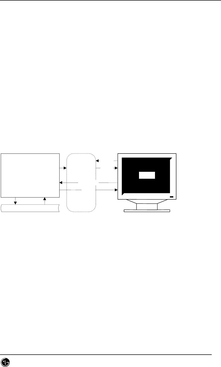
STAREX-IS BSM Manual
Page:41(877)
Issue:1.
0
SMD-011-PMA210
BSM collects and stores the data that are needed to evaluate behavior and trend that
occur in BTS and BSC and to determine the extension or reduction of the system by
interworking with BTS and BSC. Regarding the performance data collection, it is divided
into the following: to collect data in a cycle (5min./1hr./1day/1 month) and to collect the
data at the operator’s request. At the operator’s request, it displays the statistical data
that are stored or controls the statistical functions that are currently executed. The
collected data are as follows: call-related data, NE use rate, frequency of fault
occurrence, etc.
1.2.4. Security Management of System
It authorizes the manager that operates and manages BSM, develops log for messages
that are generated in the system and the command by the user and processes the
information.
All the BSM commands have the execution authority level.
Operator ID should have passwords, and when logging in, the passwords should
be input.
The user with the upper level can have all the authorities that the user with the
lower level has.
Only the user with the upper most level can change the command class.
When performing the work through the network, if there are too many users
that perform the work at the same time, all the on-line messages that come to
the system should be notified to the system and the message that comes
through the command should be displayed on the corresponding window.
BSM Application
Access
Right
Check
User
Log-in
Login
Check
Command
Out
p
ut
User Data

STAREX-IS BSM Manual
Page:42(877)
Issue:1.
0
SMD-011-PMA210
All the On-line or On-demand commands and messages should be stored.
Among the stored messages, only the messages that are desired can be
displayed by the data, time, BTS and BSC section and object number
combination.
1.2.5. Account Management of System
By allowing the user register, deletion, and information change by the manager that
operates and manages BSM, it provides the authority by the level or the user that
contains the system operation and maintenance layer to operate the stable system and
maintain the system.
User ID can be added.
User ID can be deleted.
Deletion and addition of the User ID can be made by the upper level user.
User ID information can be changed.
User ID has the following information: ID, Password, and class.
The user with the higher authority can read the user with the equal or lower
level user ID.
1.3. BSM Configuration
1.3.1. S/W System Boundary
1.3.1.1. S/W System Environment
As a unit that provides the function to operate and maintain BTS and BSC, BSM
interfaces with the CAN(Central ATM Network) and can manage up to 12 BSC and 576
BTC. When the system requirements change later, the accommodated BTS and BSC

STAREX-IS BSM Manual
Page:43(877)
Issue:1.
0
SMD-011-PMA210
counts can be changed. At the carrier’s request, it interworks with NMS to interwork
with TMN.
1.3.1.2. External Interface of the S/W System
BSM inserts the ATM Card into Workstation and has interface using CAN (Central ATM
Network) and Optic Cable/5 UTP Cable. It provides the following interface: CMIP
Interface to interface with the NMS and TCP/UDP/IP Interface to interface with BSC
and BS.
1.3.2. S/W Architecture
1.3.2.1. BSM S/W Configuration
As shown in Fig. 1-2 below, BSM S/W is configured with the following: 1) BUIS (BSS
User Interface Subsystem), 2) BEMS (BSS Element Management Subsystem), 3) BAMS
(BSS Agent Management Subsystem), and 4) BSIS (BSS System Interface Subsystem).
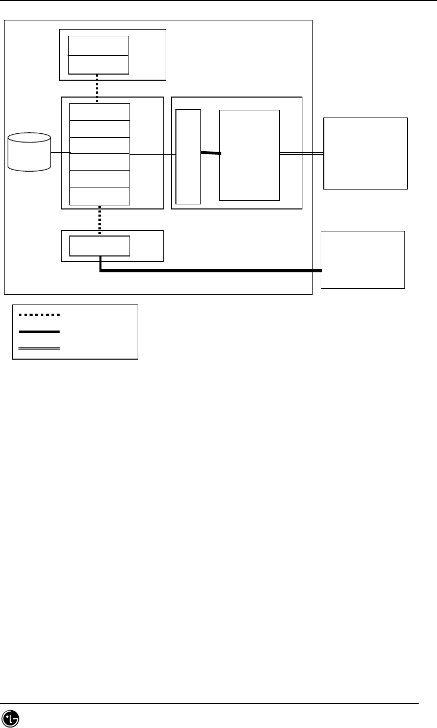
STAREX-IS BSM Manual
Page:44(877)
Issue:1.
0
SMD-011-PMA210
BSM
DBMS
R
R
I
B
A
G
E
N
T
CDMB
DLMB
STMB
TSMB
TRMB
SMMB
GUIB
MMIB
DCIB
NMS
BIUS
BEMS
BAMS
BSIS
Message Queue
TCP/UDP/IP
CMIP
CAN/BSC/BTS
Fig. 1.3-1 BSM S/W Configuration
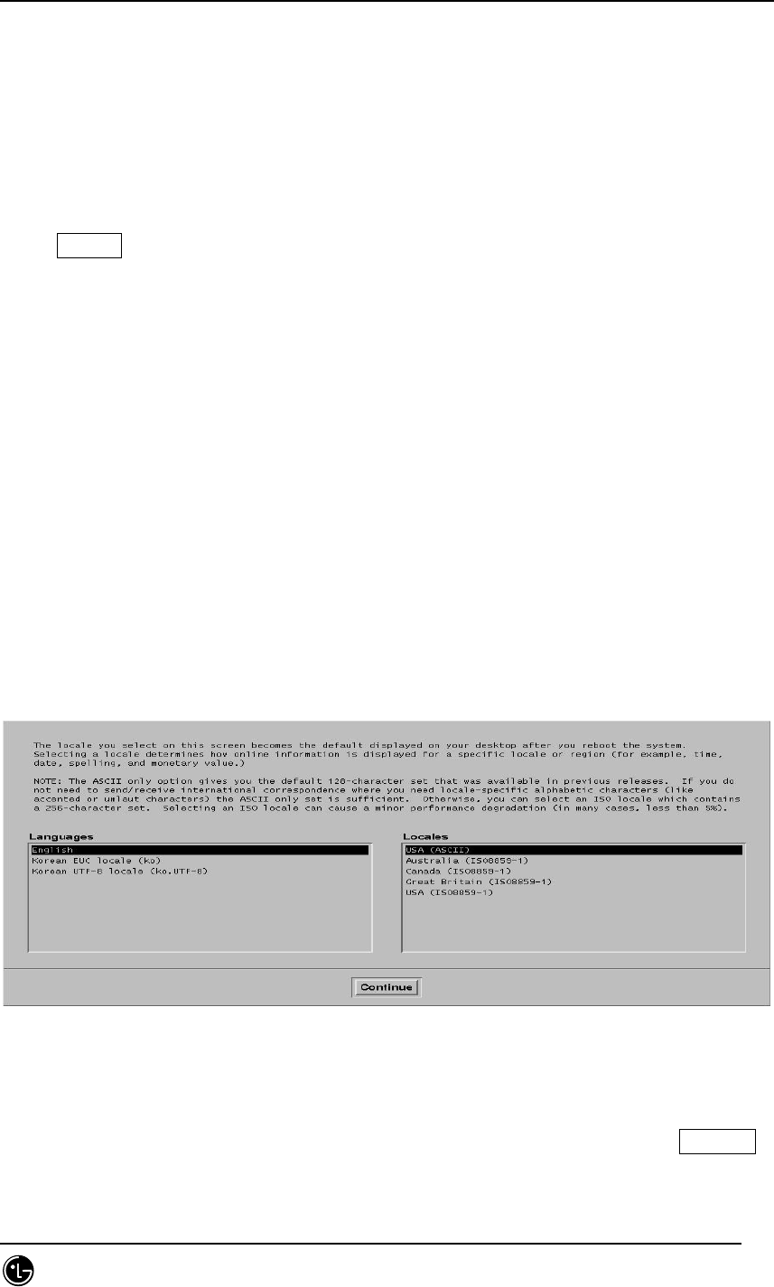
STAREX-IS BSM Manual
Page:45(877)
Issue:1.
0
SMD-011-PMA210
2. BSM Environment Setting
2.1. OS Installation
2.1.1. Solaris 2.7 Installation Procedures
1. Insert Solaris cdrom into Drive, input ID and Password in the Workstation and then
press stop+a in a login status.
Changed to a prompt state.
Input the followings:
boot cdrom
2. Check to see if OS is rebooted by the CDROM
Once booting is complete, the following will be displayed on the initial screen:
Fig. 2.1-1 OS Language Selection Screen
3. Select Korean EUC local (ko) from Language and Local items. Then, click Continue!
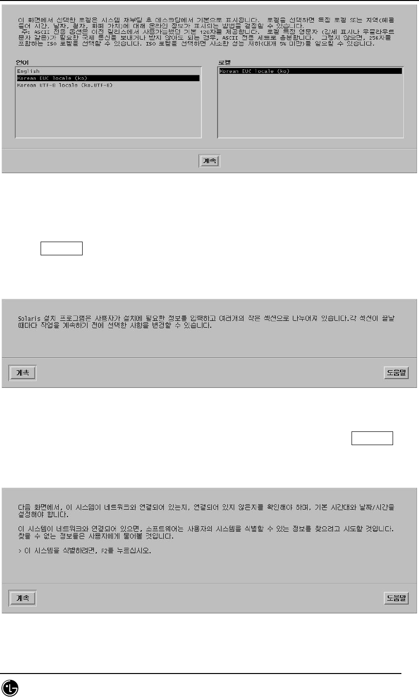
STAREX-IS BSM Manual
Page:46(877)
Issue:1.
0
SMD-011-PMA210
Fig. 2.1-2 OS Installation Language and Selection Screen 2
4. Click Continue!
5. The following is the initial screen related to the network setting. Click Continue!
Fig. 2.1-3 OS Installation Time Setting
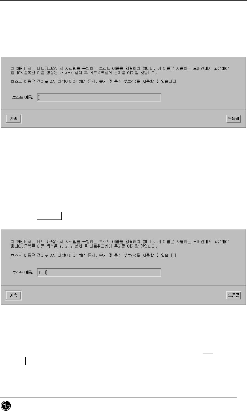
STAREX-IS BSM Manual
Page:47(877)
Issue:1.
0
SMD-011-PMA210
6. The screen that requires the host name is displayed.
Fig. 2.1-4 Host Name Input Screen
7. Input the appropriate Host name as show below. Ex) feel.
Then, click Continue!
Fig. 2.1-5 Host Name Input 2
8. Ask whether to set up the network. If the network is possible, select Yes. Click
Continue!
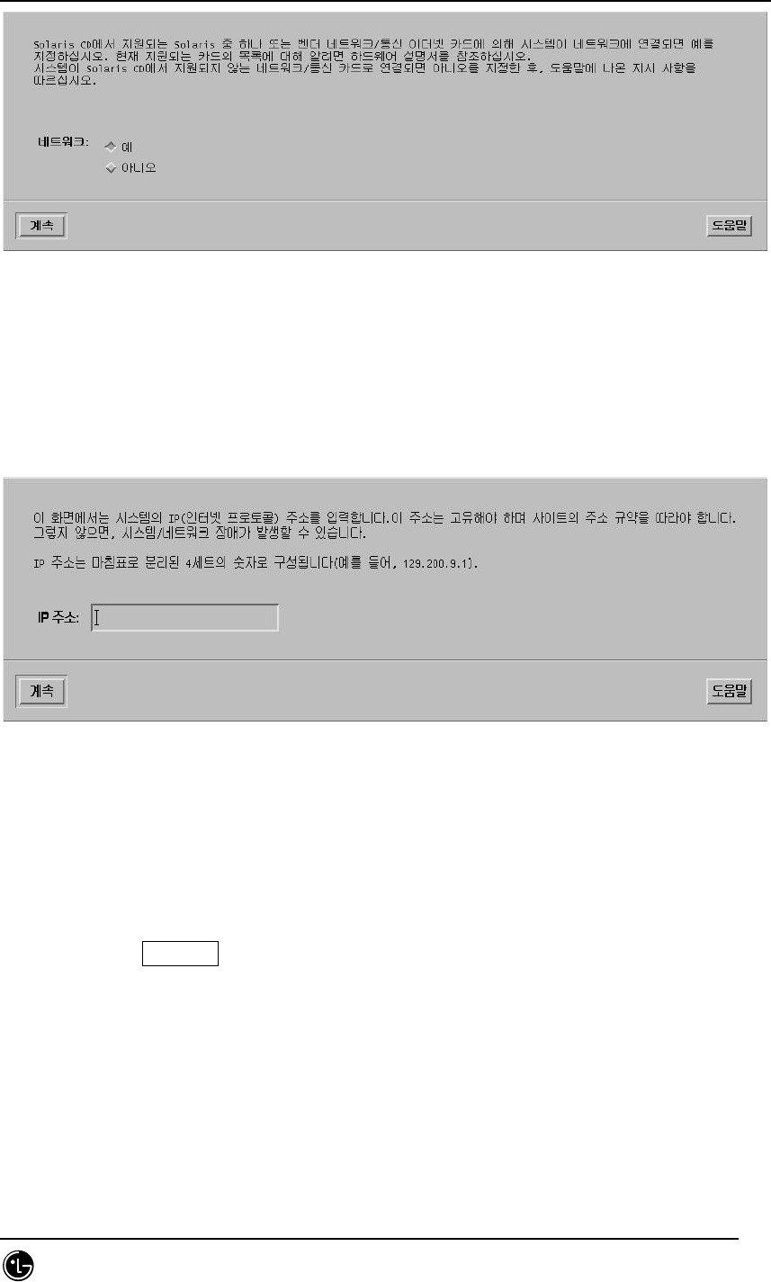
STAREX-IS BSM Manual
Page:48(877)
Issue:1.
0
SMD-011-PMA210
Fig. 2.1-6 Network Setting Screen
9. The screen asking for IP Address is displayed.
Fig. 2.1-7 IP Address Input Screen
10. Type IP address that is allocated to Workstation as shown below.
Ex) 150.150.62.102 Unique IP is given to each system.
Then, click Continue!
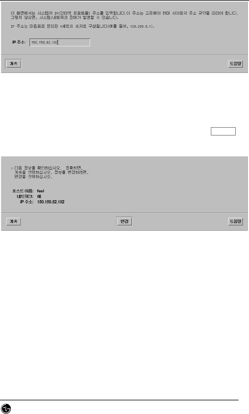
STAREX-IS BSM Manual
Page:49(877)
Issue:1.
0
SMD-011-PMA210
Fig. 2.1-8 IP Address Input Screen 2
11. The setting information is summarized on the screen as follows. Click Continue!
.
Fig. 2.1-9 Network Basic Setting Summary Screen
12. DNS(name service) select-menu is displayed
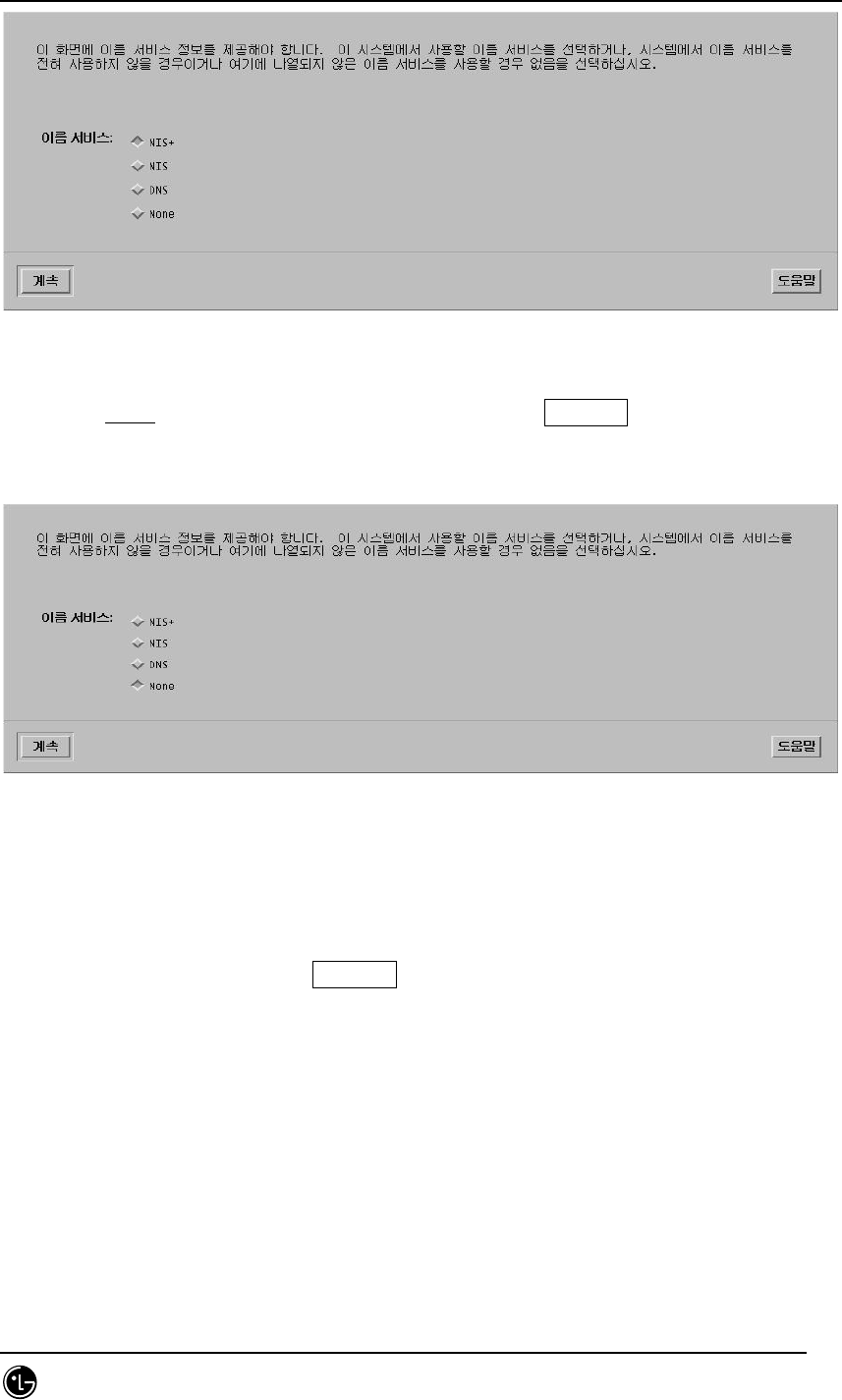
STAREX-IS BSM Manual
Page:50(877)
Issue:1.
0
SMD-011-PMA210
Fig. 2.1-10 DNS Setting Screen
13. Select None among 4 select items. (To be set) Click Continue!
Fig. 2.1-11 DNS Setting Screen 2
14. OK menu is displayed. Click Continue!
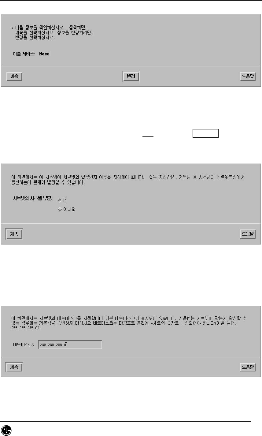
STAREX-IS BSM Manual
Page:51(877)
Issue:1.
0
SMD-011-PMA210
Fig. 2.1-12 DNS Setting Summary Screen
15. Subnet setting screen is displayed. Select Yes. Then, click Continue!
Fig. 2.1-13 Subnet Setting Screen
16. The subnet mask IP inputting part is shown.
Fig. 2.1-14 Subnet Setting Screen 2
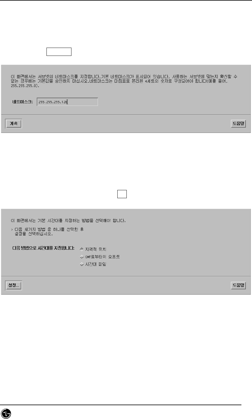
STAREX-IS BSM Manual
Page:52(877)
Issue:1.
0
SMD-011-PMA210
17. Type the subnet mask as shown below.
Ex) 255.255.255.128 (before inputting them, check if the subnet mask is used)
Then, click Continue!
Fig. 2.1-15 Subnet Setting Screen 3
18. The menu designating the basic time zone is shown.
Select the regional location. Then, click Set!
Fig. 2.1-16 OS Time Setting Method Screen
19. The menu containing the country and time zone is shown.
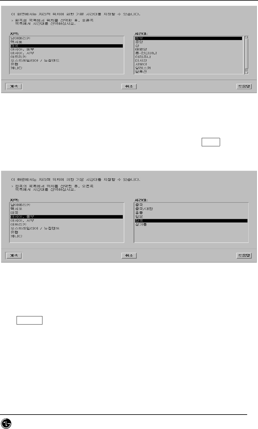
STAREX-IS BSM Manual
Page:53(877)
Issue:1.
0
SMD-011-PMA210
Fig. 2.1-17 OS Time Setting Region Selection Screen
20. Select Asia for the region and Korean for time zone. Then, click Select!
Fig. 2.1-18 OS Time Setting Region Selection Screen 2
21. Check to see if minute, time, data, month, and year are accurate. If they are not,
click Continue!
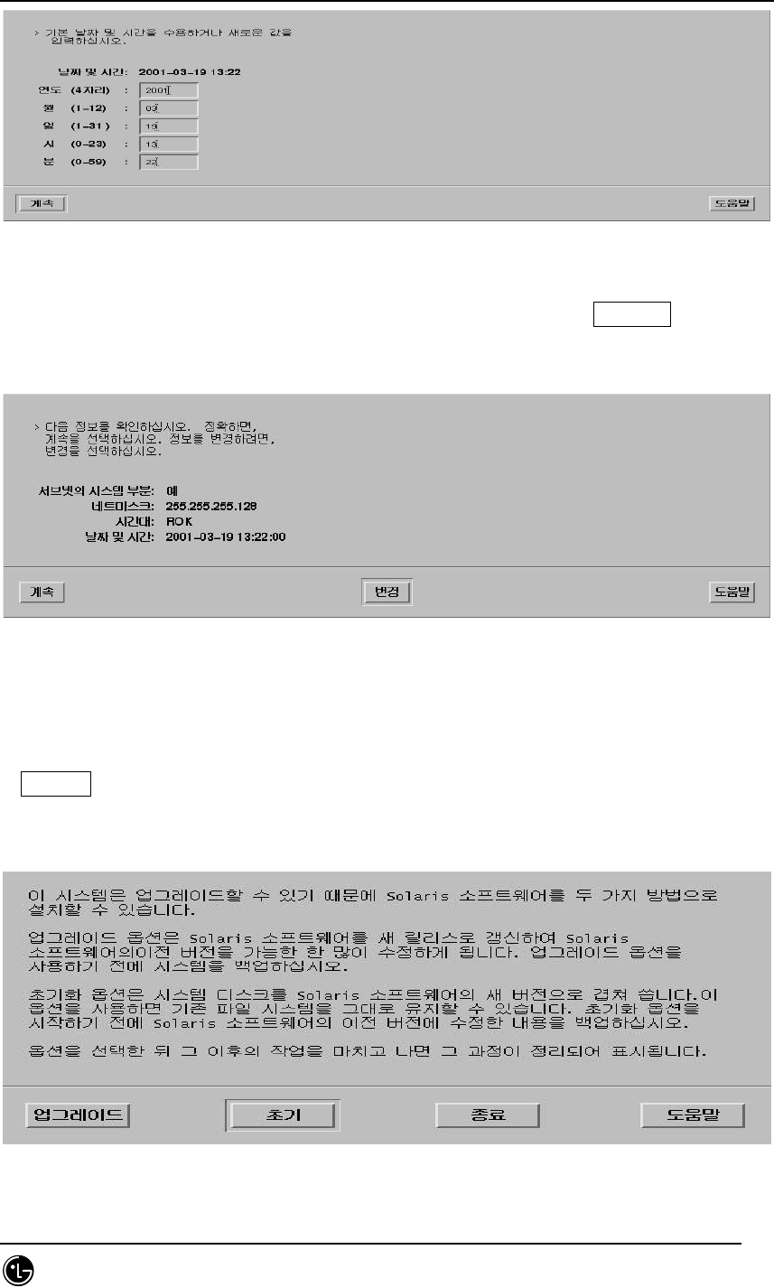
STAREX-IS BSM Manual
Page:54(877)
Issue:1.
0
SMD-011-PMA210
Fig. 2.1-19 Time Setting Screen
22. The items that are related to the subnet are summarized. Click Continue!
Fig. 2.1-20 Subnet and Time Setting Summary Screen
23. The screen selecting Solaris installation method is displayed on the screen. Click
Initialize!
Fig. 2.1-21 OS Installation Method Selection Screen
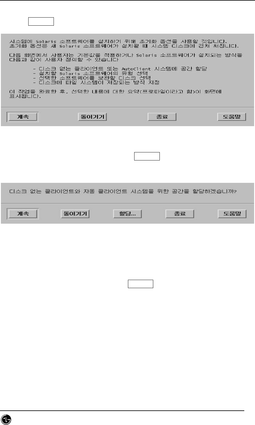
STAREX-IS BSM Manual
Page:55(877)
Issue:1.
0
SMD-011-PMA210
24. Click Continue!
Fig. 2.1-22 Attention to the Installation of OS
25. Client-related questions are shown. Click Continue!
Fig. 2.1-23 X-Terminal Setting Screen
26. Language select screen is shown. Click Continue!
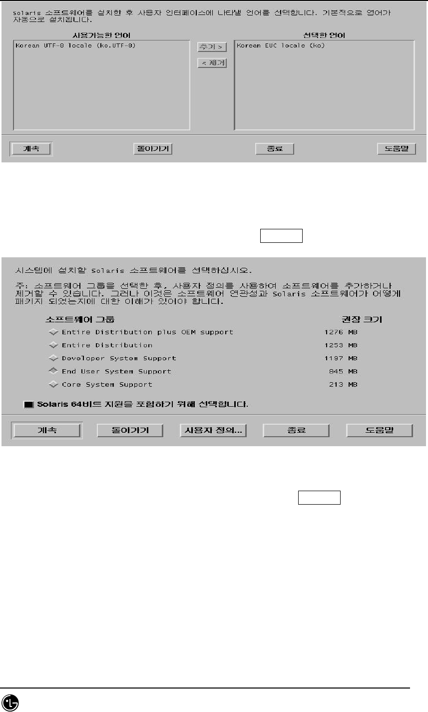
STAREX-IS BSM Manual
Page:56(877)
Issue:1.
0
SMD-011-PMA210
Fig. 2.1-24 User Language Selection Screen
27. S/W installation-related menu is displayed. Click Continue!
Fig. 2.1-25 OS Installation Category Selection Screen
28. Select Entire Distribution plus OEM support. Then, click Continue!
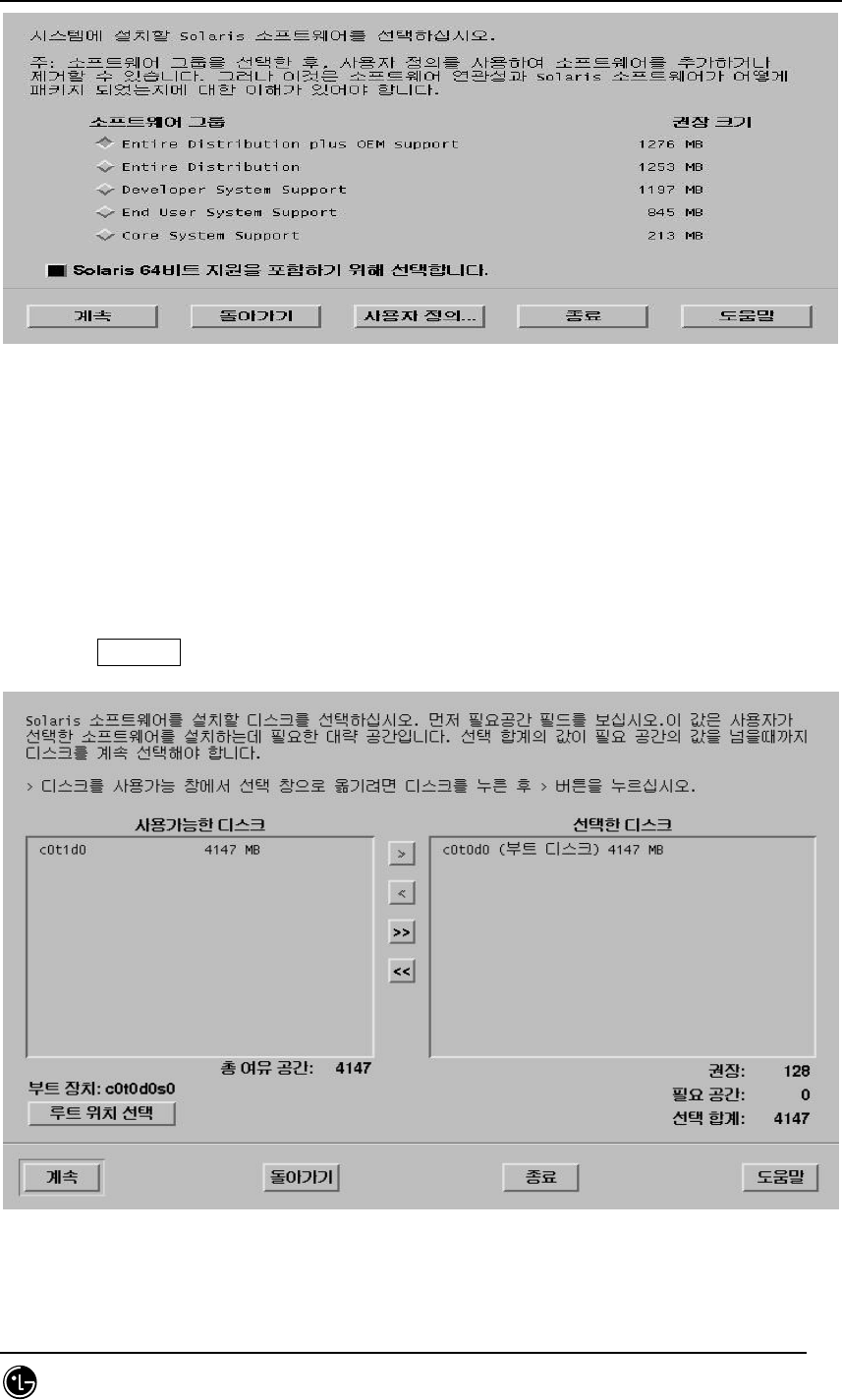
STAREX-IS BSM Manual
Page:57(877)
Issue:1.
0
SMD-011-PMA210
Fig. 2.1-26 OS Installation Category Selection Screen 2
29. Select the disk where OS is to be installed.
If two disks are displayed on the screen, it shows information.
t : Select the disk with t0 - a parameter that represents the disk – written.
Click Continue!
Fig. 2.1-27 OS Installation Disk Selection Screen
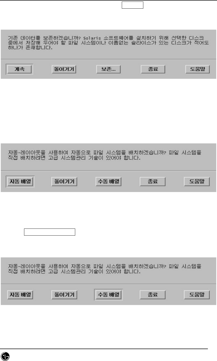
STAREX-IS BSM Manual
Page:58(877)
Issue:1.
0
SMD-011-PMA210
30. Determine whether to keep data. Then, click Continue!
Fig. 2.1-28 Warning Sentence Screen Resulting from the Disk Setting
31. File system-related items are shown.
Fig. 2.1-29 Selection Screen for Disk Installation Method
32. Click Manual Arrangement!
Fig. 2.1-30 Select Screen for Disk Installation Method
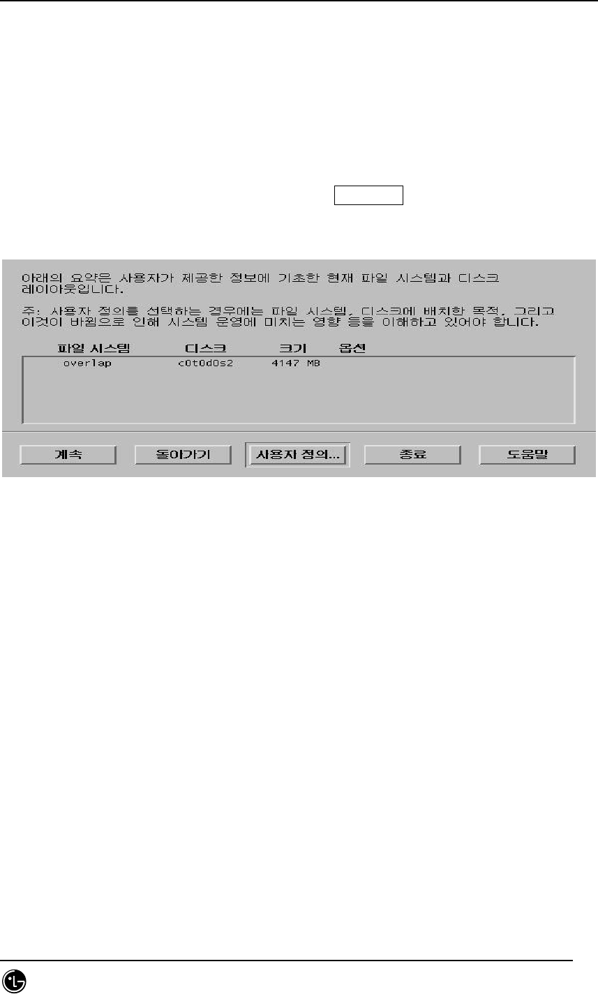
STAREX-IS BSM Manual
Page:59(877)
Issue:1.
0
SMD-011-PMA210
33. The current disk information is shown. Click Customize!
Fig. 2.1-31 Selected Disk Information Display Screen
34. Disk use information is shown. Overlap(disk size) can be checked.
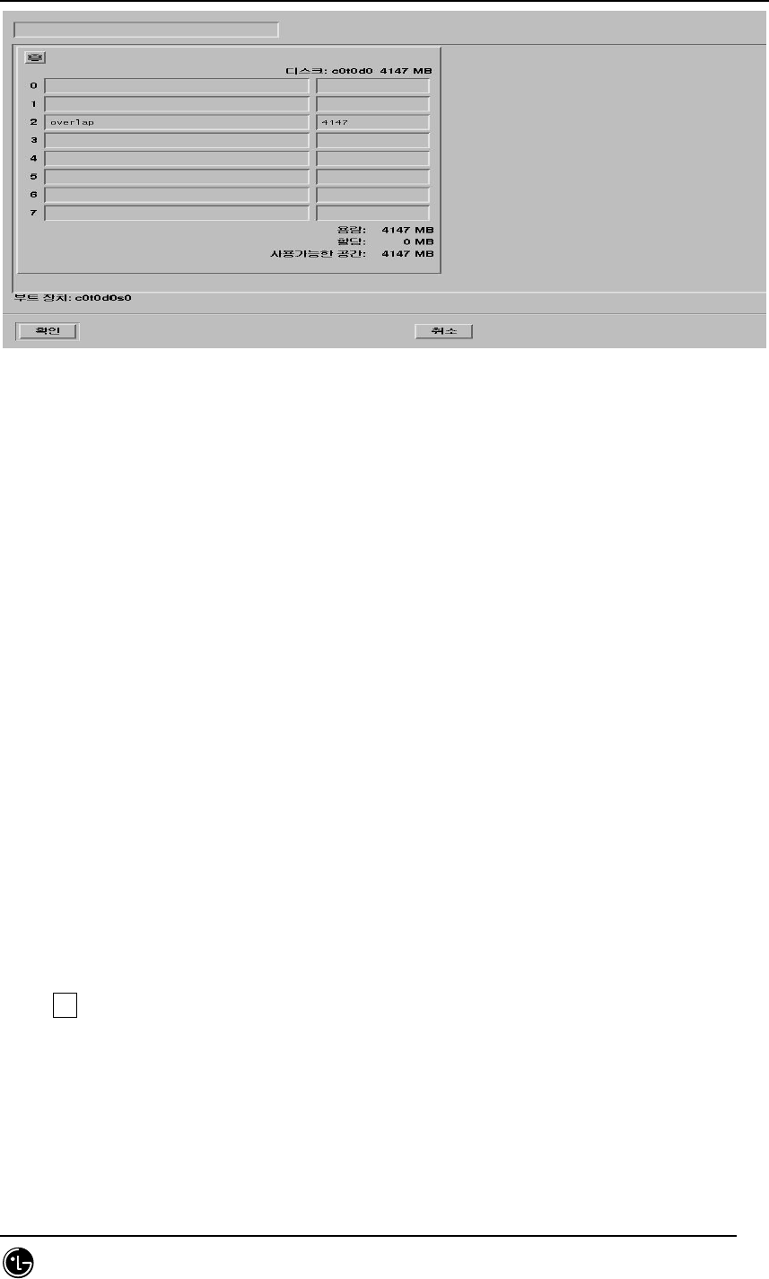
STAREX-IS BSM Manual
Page:60(877)
Issue:1.
0
SMD-011-PMA210
Fig. 2.1-32 Area Information Display Screen for the Disk Division
35. Disk Space Allocation
As shown below, type route(/), user(/usr), and swap and select the size to the total disk
space. In general, much of disk space is allocated to Route /usr. (For the suitable Disk
Size, refer to the attached file.)
Swap should be twice as large as the memory. (Current system memory : 256Mbyte)
Click OK!
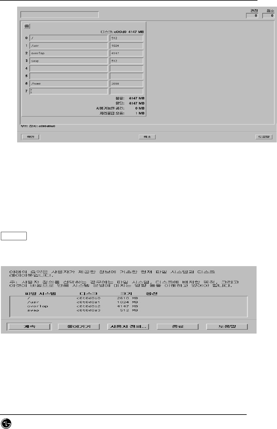
STAREX-IS BSM Manual
Page:61(877)
Issue:1.
0
SMD-011-PMA210
36. The screen that reconfirms the disk space arrangement that is previously set. Click
Continue!
Fig. 2.1-33 Disk Allocation Result Display Screen
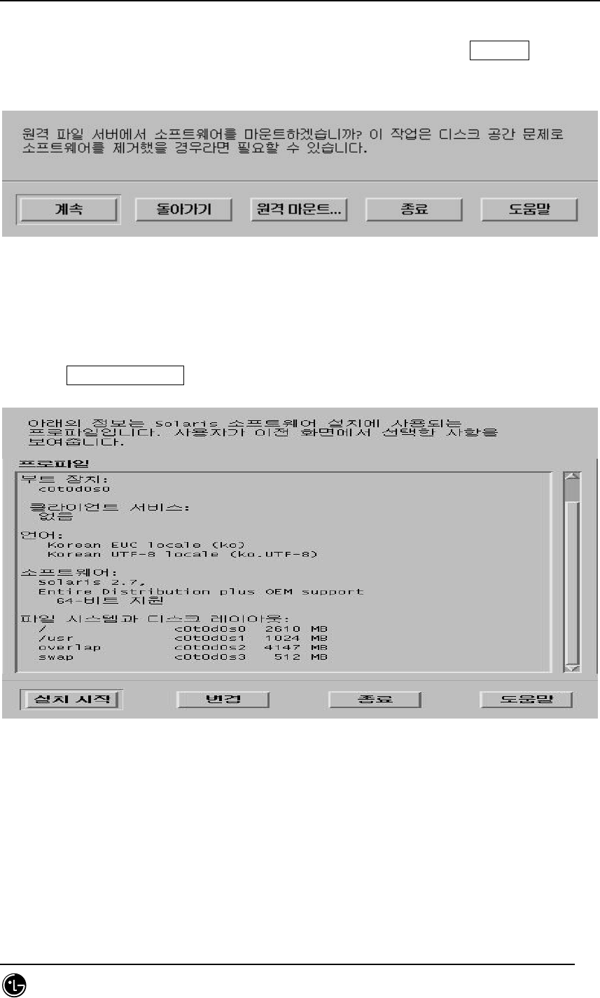
STAREX-IS BSM Manual
Page:62(877)
Issue:1.
0
SMD-011-PMA210
37. Items that are related to the remote file server are shown. Click Continue!
Fig. 2.1-34 Remote File Server Installation Screen
38. Click Start Installation for final installation.
Fig. 2.1-35 Set up Information Display Screen for the Installation

STAREX-IS BSM Manual
Page:63(877)
Issue:1.
0
SMD-011-PMA210
2.1.2. Network Environment Setting Procedures
The following material is developed taking the BSM feel system as an example.
Attention : If the setting is not done inappropriately, C-compiler or Informix cannot be
installed.
1. After booting is done, change shell of root to c-shell(default : bourne shell).
Purpose : to use the C-Shell
2. Create .cshrc & .login file.
Purpose : After booting, create .cshrc &.login file in the root.
3. Create resolv.conf.
Modified Contents
$cd /etc
$vi passwd
Correct root:x:0:1:Super-User:/:/sbin/sh in the first line/
Modified Items : sbin/shbin/csh
cp /etc/skel/local.cshrc /.cshrc
cp /etc/skel/local.login /.login
vi /etc/resolv.conf
domain
lgic.co.kr
nameserver 165.243.140.230

STAREX-IS BSM Manual
Page:64(877)
Issue:1.
0
SMD-011-PMA210
4. Create the hosts file.
Items to be added to the Internet host table on top.
Attention : If inputting feel.lgic.co.kr loghost, BSM might not operate.
5. Create nsswitch.conf.
Add dns to the line where the host exists.
6. Create defaultrouter.
Input Router IP.
7. Create defaultdomain.
127.0.0.1 localhost
150.150.62.102 feel.lgic.co.kr feel loghost
vi /etc/hosts
: vi /etc/nsswitch.conf
hosts: files dns
vi /etc/defaultrouter
150.150.62.126

STAREX-IS BSM Manual
Page:65(877)
Issue:1.
0
SMD-011-PMA210
Input domain name.
8. Test the network.
Network Setting Test
Ping result : 150.150.62.64 is alive it means that the network is set up.
vi /etc/defaultdomain
lgic.co.kr
ping 150.150.62.100

STAREX-IS BSM Manual
Page:66(877)
Issue:1.
0
SMD-011-PMA210
2.2. DBMS(Informix) Installation
2.2.1. Informix Install
2.2.1.1. Preparation for Installation
Note> The host name that is used in this document as an example is zen and Informix
home directory path is /home/Informix.
2.2.1.1.1. Informix Account Creation
In order to install Informix, the informix user account of the informix group is required.
Account can be made by the following methods: the method that uses admintool and
the method that directly modifies the file.
2.2.1.1.1.1. First Method – execute admintool
1. Informix group generation: create a group under the name of informix on
the Group Add menu.
2. Informix user generation: create a user under the name of informix on the
Us Add menu.
2.2.1.1.1.2. Second Method – modify the file directly
Add informix group/ to the etc/group file
and add informix account as informix group in a /etc/passwd file.
Authorize the informix user by making an informix homedirectory.
2.2.1.1.2. Informix Installation File Copy
Log in to the informix account in order to install Informix. Move the Informix
installation file to the home directory in the informix account. Then, release all the
compression to create the Install Script in the Informix Directory. (Ex. installsql,
installserver, installconn, etc)

STAREX-IS BSM Manual
Page:67(877)
Issue:1.
0
SMD-011-PMA210
$ cd /cdrom/informix/
$ ls –al (check the path where the Informix product is located)
$ cd $INFORMIXDIR (informix Home Directory)
$ tar xvf /cdrom/informix/ICONNECT/SUN/CONNECT.TAR <= Informix Dynamic
Server CD
$ tar xvf /cdrom/informix/SERVER/IDS.TAR <= Informix Dynamic Server CD
$ tar xvf /cdrom/informix/SQLRT.TAR <= Informix SQL CD
2.2.1.2. Environment File Modification
To install informix, modify the system file, services file, etc and then perform
rebooting.
2.2.1.2.1. /etc/ System Modification
set msgsys:msginfo_msgmap=256
set msgsys:msginfo_msgmax=1024
set msgsys:msginfo_msgmnb=614400
set msgsys:msginfo_msgmni=50
set msgsys:msginfo_msgssz=128
set msgsys:msginfo_msgtql=1200
set msgsys:msginfo_msgseg=16384
set shmsys:shminfo_shmmax=104858000
#set shmsys:shminfo_shmmin=10
set shmsys:shminfo_shmmni=100
set shmsys:shminfo_shmseg=100
#set shmsys:shminfo_shmbrk=10485800
set semsys:seminfo_semmap=64
set semsys:seminfo_semmni=128
set semsys:seminfo_semmsl=64
set semsys:seminfo_semmns=8192
set semsys:seminfo_semmnu=4096
set semsys:seminfo_semume=64

STAREX-IS BSM Manual
Page:68(877)
Issue:1.
0
SMD-011-PMA210
set pt_cnt=120
2.2.1.2.2. /etc/services File Modification
sqlexec 5000/tcp
2.2.1.2.3. Addition to .cshrc file
Add the following to .cshrc file in the user account that uses the root, informix, and
Informix and then execute the source .cshrc command.
#
# Informix Environment
#
setenv INFORMIXDIR /home/Informix
setenv INFORMIXSERVER zen_tcp
=> Use TCP connection. (when using semaphore: zen)
setenv PATH $INFORMIXDIR/bin:$PATH
setenv LD_LIBRARY_PATH $INFORMIXDIR/lib:$INFORMIXDIR/lib/esql:/usr/lib
setenv TERMCAP $INFORMIXDIR/etc/termcap
setenv DBTEMP $INFORMIXDIR/tmp -> Create a tmp directory directly
setenv ONCONFIG onconfig
setenv INFORMIXC cc
setenv TERM vt100
2.2.1.2.4. Addition to .login file
# @(#)login 2.0 Apr 5 1995 TriGem
stty echoe
stty erase ^H
stty cs8 -istrip defeucw
setenv LANG C >& /dev/null

STAREX-IS BSM Manual
Page:69(877)
Issue:1.
0
SMD-011-PMA210
setenv DISPLAY unix:0
stty -istrip
# Aliasing ................................
setenv EXINIT 'set aw terse|map @ dd|map # x'
echo -n " Terminal type is ($term): "
set X = $<
if $X != "" then
set term = $X
endif
if $X == "sun" then
stty erase ^H
stty werase ^?
endif
if $X == "fast" then
stty erase ^H
stty werase '^?'
endif
tset -I –Q
2.2.1.2.5. Rebooting
#sync
#sync
#sync
..
# reboot
2.2.1.3. Informix Installation
Let’s install informix.
Note> The host name that is used in this document as an example is zen and the
informix home directory path is /home/informix.
2.2.1.3.1. Installing install file in order
Install the following in order: installsqlrt<root>, installserver<root>,
installconn<Informix>. At this point, input serial numbers and key.

STAREX-IS BSM Manual
Page:70(877)
Issue:1.
0
SMD-011-PMA210
In the <root> account
# installsqlrt
INFORMIX-SQL Run Time Facility Version 7.30.UC4
Copyright (C) 1984-2000 Informix Software, Inc.
Installation Script
This installation procedure must be run by root (super-user).
It will change the owner, group, and mode of all files of this
package in this directory. There must be a user "informix" and a
group "informix" known to the system.
Press RETURN to continue,
or the interrupt key (usually CTRL-C or DEL) to abort. RETURN
Enter your serial number (for example, INF#X999999) >
Serial number
Enter your serial number KEY (uppercase letters only) >
Key
WARNING!
This software, and its authorized use and number of users, are
subject to the applicable license agreement with Informix Software, Inc.
If the number of users exceeds the licensed number, the excess users may
be prevented from using the software. UNAUTHORIZED USE OR COPYING MAY
SUBJECT YOU AND YOUR COMPANY TO SEVERE CIVIL AND CRIMINAL LIABILITIES.
Press RETURN to continue,

STAREX-IS BSM Manual
Page:71(877)
Issue:1.
0
SMD-011-PMA210
or the interrupt key (usually CTRL-C or DEL) to abort.
Installing directory .
Installing directory bin
Installing directory etc
Installing directory msg
Installing directory msg/en_us
Installing directory msg/en_us/0333
Installing directory msg/ja_jp
:
:
:
Installing directory gls/lc11/th_th
Installing directory gls/lc11/zh_cn
Installing directory gls/lc11/zh_tw
Installation of INFORMIX-SQL, Runtime Facility complete.
:
:
#installserver <= Perform identically
Informix Dynamic Server Version 7.31.UC7

STAREX-IS BSM Manual
Page:72(877)
Issue:1.
0
SMD-011-PMA210
Copyright (C) 1986-2000 Informix Software, Inc.
Installation and Configuration Script
This installation procedure must be run by a privileged user (Super User)
It will change the owner, group, mode, (and other file attributes on
Secure systems) of all files of this package in this directory.
There must be a user "informix" and a group "informix" known to the system.
Press RETURN to continue,
or the interrupt key (usually CTRL-C or DEL) to abort.
:
:
:
Installing directory gls/lc11/zh_tw
Installing directory bitmaps
Installing Shared Libraries in System Directories ...
Linking /usr/lib/ismdd07b.so from lib/ismdd07b.so
Linking /usr/lib/iosm07a.so from lib/iosm07a.so

STAREX-IS BSM Manual
Page:73(877)
Issue:1.
0
SMD-011-PMA210
Linking /usr/lib/ipldd07a.so from lib/ipldd07a.so
Installation of Informix Dynamic Server complete.
In the <Informix> account
#installconn
INFORMIX-Connect Version 2.40.UC1
Copyright (C) 1984-1999 Informix Software, Inc.
Installation Script
Installation Script Requirements:
- A user "informix" and a group "informix" must be known to the system.
- The product source files must have been loaded by user informix
- This installation procedure must be run by user informix.
- You must also set INFORMIXDIR to where you would like to install
the product on and make INFORMIXDIR as your current working directory.
This script will change the owner, group, and mode of
many of the files of this package in this directory.
Extracting files from conncontent file... <= Wait until the compressed file is
unzipped.
Installing I-Connect as user "informix"...
Press RETURN to continue,
or the interrupt key (usually CTRL-C or DEL) to abort.
Enter your serial number (for example, INF#X999999) >
Serial number
Enter your serial number KEY (uppercase letters only) >

STAREX-IS BSM Manual
Page:74(877)
Issue:1.
0
SMD-011-PMA210
KEY
WARNING!
This software, and its authorized use and number of users, are
subject to the applicable license agreement with Informix Software, Inc.
If the number of users exceeds the licensed number, the excess users may
be prevented from using the software. UNAUTHORIZED USE OR COPYING MAY
SUBJECT YOU AND YOUR COMPANY TO SEVERE CIVIL AND CRIMINAL LIABILITIES.
Press RETURN to continue,
or the interrupt key (usually CTRL-C or DEL) to abort.
Installing directory .
Installing directory etc
Installing directory msg
:
:
:
Installing directory gls/lc11/zh_cn
Installing directory gls/lc11/zh_tw
**************************************************************
To complete the installation of INFORMIX-Connect,
run /home/informix/RUN_AS_ROOT.conn as root.
**************************************************************
Informix user portion of installation of INFORMIX-Connect complete.
2.2.1.3.2. Shared Library Linking
Once the above work is complete, change the user ID of part of the execution files to
root for the informix file and link shared libraries. This work can check if
RUN_AS_ROOT.SERVER file is generated within the $INFORMIXDIR after performing
the install script.

STAREX-IS BSM Manual
Page:75(877)
Issue:1.
0
SMD-011-PMA210
#RUN_AS_ROOT.conn -> perform root.
Informix Product: INFORMIX-Connect
Installation Directory: /home/informix
Performing root portion of installation of INFORMIX-Connect...
Installation of INFORMIX-Connect complete.
2.2.2. Environment Setting
2.2.2.1. onconfig file
Let’s create the etc/onconfig in the informix account. Copy the existing onconfig.std
file to the onconfig file and then modify and add the following paths and parameters. In
the example below, the Informix path is /home/informix and the host name is zen.
Modify them suitable to your system.
#
# INFORMIX SOFTWARE, INC.
#
# Title: onconfig.std
# Description: Informix Dynamic Server Configuration Parameters
#
#**************************************************************************
# Root Dbspace Configuration
ROOTNAME rootdbs # Root dbspace name
ROOTPATH /home/informix/DBS/root_chk # Path for device containing root
dbspace
ROOTOFFSET 0 # Offset of root dbspace into device (Kbytes)
ROOTSIZE 100000 # Size of root dbspace (Kbytes)
# Disk Mirroring Configuration Parameters
MIRROR 1 # Mirroring flag (Yes = 1, No = 0)

STAREX-IS BSM Manual
Page:76(877)
Issue:1.
0
SMD-011-PMA210
MIRRORPATH # Path for device containing mirrored root
MIRROROFFSET 0 # Offset into mirrored device (Kbytes)
# Physical Log Configuration
PHYSDBS rootdbs # Location (dbspace) of physical log
PHYSFILE 10000 # Physical log file size (Kbytes)
# Logical Log Configuration
LOGFILES 10 # Number of logical log files
LOGSIZE 3000 # Logical log size (Kbytes)
# Diagnostics
MSGPATH /home/informix/online.log # System message log file path
CONSOLE /dev/console # System console message path
ALARMPROGRAM /home/informix/etc/no_log.sh # Alarm program path
SYSALARMPROGRAM /home/informix/etc/evidence.sh # System Alarm program path
TBLSPACE_STATS 1
# System Archive Tape Device
TAPEDEV /dev/null # Tape device path
#TAPEDEV /dev/tapedev # Tape device path
TAPEBLK 16 # Tape block size (Kbytes)
TAPESIZE 10240 # Maximum amount of data to put on tape (Kbytes)
# Log Archive Tape Device
LTAPEDEV /dev/null # Log tape device path
#LTAPEDEV /dev/tapedev # Log tape device path
LTAPEBLK 16 # Log tape block size (Kbytes)
LTAPESIZE 10240 # Max amount of data to put on log tape (Kbytes)
# Optical
STAGEBLOB # Informix Dynamic Server/Optical staging area
# System Configuration
SERVERNUM 0 # Unique id corresponding to a Dynamic Server
instance
DBSERVERNAME zen # Name of default database server

STAREX-IS BSM Manual
Page:77(877)
Issue:1.
0
SMD-011-PMA210
DBSERVERALIASES zen_tcp # List of alternate dbservernames
NETTYPE ipcshm,1,10,CPU # When using semaphore, it is good to increase the
setting with 10 connection to 50.
NETTYPE tlitcp,1,10,NET # Configure poll thread(s) for nettype
DEADLOCK_TIMEOUT 60 # Max time to wait of lock in distributed env.
RESIDENT 0 # Forced residency flag (Yes = 1, No = 0)
MULTIPROCESSOR 0 # 0 for single-processor, 1 for multi-processor
NUMCPUVPS 1 # Number of user (cpu) vps
SINGLE_CPU_VP 1 # If non-zero, limit number of cpu vps to one
NOAGE 0 # Process aging
AFF_SPROC 0 # Affinity start processor
AFF_NPROCS 0 # Affinity number of processors
# Shared Memory Parameters
LOCKS 100000 # Maximum number of locks
BUFFERS 12800 # Maximum number of shared buffers
NUMAIOVPS 1 # Number of IO vps
PHYSBUFF 32 # Physical log buffer size (Kbytes)
LOGBUFF 32 # Logical log buffer size (Kbytes)
LOGSMAX 20 # Maximum number of logical log files
CLEANERS 1 # Number of buffer cleaner processes
SHMBASE 0x0A000000L # Shared memory base address
SHMVIRTSIZE 30000 # initial virtual shared memory segment size
SHMADD 16000 # Size of new shared memory segments (Kbytes)
SHMTOTAL 0 # Total shared memory (Kbytes). 0=>unlimited
CKPTINTVL 300 # Check point interval (in sec)
LRUS 8 # Number of LRU queues
LRU_MAX_DIRTY 60 # LRU percent dirty begin cleaning limit
LRU_MIN_DIRTY 50 # LRU percent dirty end cleaning limit
LTXHWM 50 # Long transaction high water mark percentage
LTXEHWM 60 # Long transaction high water mark (exclusive)
TXTIMEOUT 300 # Transaction timeout (in sec)
STACKSIZE 32 # Stack size (Kbytes)

STAREX-IS BSM Manual
Page:78(877)
Issue:1.
0
SMD-011-PMA210
# System Page Size
# BUFFSIZE - Dynamic Server no longer supports this configuration parameter.
# To determine the page size used by Dynamic Server on your platform
# see the last line of output from the command, 'onstat -b'.
# Recovery Variables
# OFF_RECVRY_THREADS:
# Number of parallel worker threads during fast recovery or an offline restore.
# ON_RECVRY_THREADS:
# Number of parallel worker threads during an online restore.
OFF_RECVRY_THREADS 10 # Default number of offline worker threads
ON_RECVRY_THREADS 1 # Default number of online worker threads
# Data Replication Variables
# DRAUTO: 0 manual, 1 retain type, 2 reverse type
DRAUTO 0 # DR automatic switchover
DRINTERVAL 30 # DR max time between DR buffer flushes (in sec)
DRTIMEOUT 30 # DR network timeout (in sec)
DRLOSTFOUND /home/informix/etc/dr.lostfound # DR lost+found file path
# CDR Variables
CDR_LOGBUFFERS 2048 # size of log reading buffer pool (Kbytes)
CDR_EVALTHREADS 1,2 # evaluator threads (per-cpu-vp,additional)
CDR_DSLOCKWAIT 5 # DS lockwait timeout (seconds)
CDR_QUEUEMEM 4096 # Maximum amount of memory for any CDR queue
(Kbytes)
CDR_LOGDELTA 30 # % of log space allowed in queue memory
CDR_NUMCONNECT 16 # Expected connections per server
CDR_NIFRETRY 300 # Connection retry (seconds)
CDR_NIFCOMPRESS 0 # Link level compression (-1 never, 0 none, 9 max)
# Backup/Restore variables
BAR_ACT_LOG /tmp/bar_act.log
BAR_MAX_BACKUP 0
BAR_RETRY 1

STAREX-IS BSM Manual
Page:79(877)
Issue:1.
0
SMD-011-PMA210
BAR_NB_XPORT_COUNT 10
BAR_XFER_BUF_SIZE 31
# Informix Storage Manager variables
ISM_DATA_POOL ISMData # If the data pool name is changed, be sure to
# update $INFORMIXDIR/bin/onbar. Change to
# ism_catalog -create_bootstrap -pool <new name>
ISM_LOG_POOL ISMLogs
# Read Ahead Variables
RA_PAGES 32 # Number of pages to attempt to read ahead
RA_THRESHOLD 30 # Number of pages left before next group
# DBSPACETEMP:
# Dynamic Server equivalent of DBTEMP for SE. This is the list of dbspaces
# that the Dynamic Server SQL Engine will use to create temp tables etc.
# If specified it must be a colon separated list of dbspaces that exist
# when the Dynamic Server system is brought online. If not specified, or if
# all dbspaces specified are invalid, various ad hoc queries will create
# temporary files in /tmp instead.
DBSPACETEMP # Default temp dbspaces
# DUMP*:
# The following parameters control the type of diagnostics information which
# is preserved when an unanticipated error condition (assertion failure) occurs
# during Dynamic Server operations.
# For DUMPSHMEM, DUMPGCORE and DUMPCORE 1 means Yes, 0 means No.
DUMPDIR /tmp # Preserve diagnostics in this directory
DUMPSHMEM 0 # Dump a copy of shared memory
DUMPGCORE 0 # Dump a core image using 'gcore'
DUMPCORE 0 # Dump a core image (Warning:this aborts Dynamic
Server)
DUMPCNT 1 # Number of shared memory or gcore dumps for
# a single user's session

STAREX-IS BSM Manual
Page:80(877)
Issue:1.
0
SMD-011-PMA210
FILLFACTOR 90 # Fill factor for building indexes
# method for Dynamic Server to use when determining current time
USEOSTIME 0 # 0: use internal time(fast), 1: get time from OS(slow)
# Parallel Database Queries (pdq)
MAX_PDQPRIORITY 100 # Maximum allowed pdqpriority
DS_MAX_QUERIES # Maximum number of decision support queries
DS_TOTAL_MEMORY # Decision support memory (Kbytes)
DS_MAX_SCANS 1048576 # Maximum number of decision support scans
DATASKIP # List of dbspaces to skip
# OPTCOMPIND
# 0 => Nested loop joins will be preferred (where
# possible) over sortmerge joins and hash joins.
# 1 => If the transaction isolation mode is not
# "repeatable read", optimizer behaves as in (2)
# below. Otherwise it behaves as in (0) above.
# 2 => Use costs regardless of the transaction isolation
# mode. Nested loop joins are not necessarily
# preferred. Optimizer bases its decision purely
# on costs.
OPTCOMPIND 0 # To hint the optimizer
ONDBSPACEDOWN 2 # Dbspace down option: 0 = CONTINUE, 1 = ABORT, 2
= WAIT
LBU_PRESERVE 1 # Preserve last log for log backup
OPCACHEMAX 0 # Maximum optical cache size (Kbytes)
# HETERO_COMMIT (Gateway participation in distributed transactions)
# 1 => Heterogeneous Commit is enabled
# 0 (or any other value) => Heterogeneous Commit is disabled
HETERO_COMMIT 0
# Optimization goal: -1 = ALL_ROWS(Default), 0 = FIRST_ROWS
OPT_GOAL -1

STAREX-IS BSM Manual
Page:81(877)
Issue:1.
0
SMD-011-PMA210
# Optimizer DIRECTIVES ON (1/Default) or OFF (0)
DIRECTIVES 1
# Status of restartable restore
RESTARTABLE_RESTORE OFF
2.2.2.2. sqlhosts File
Copy the etc/sqlhosts.demo file in the Informix account to the sqlhosts file and then
modify them suitable to the system.
zen onipcshm zen sqlexecshm
zen_tcp ontlitcp zen sqlexec
2.2.2.3. onconfig Parameter Setting
Input the onmonitor command on the prompt
# onmonitor
* If creating dbspace using the cooked file, create null file.
# cd $INFORMIXDIR
# mkdir DBS
# cd DBS
# touch root_chk
# chmod 660 root_chk
2.2.3. Execution
Now, the Informix installation and environment setting are complete. Let’s execute the
Informix.
# oninit –isy <= DB Execution
# onmode –my <= Convert DB into online mode
#onstat – <= DB Status viewing
Informix Dynamic Server Version 7.31.UC7 -- On-Line -- Up 00:01:00 -- 62752
Kbytes

STAREX-IS BSM Manual
Page:82(877)
Issue:1.
0
SMD-011-PMA210
#
2.2.4. Others
2.2.4.1. Command Usage Viewing
command -- <= Give – option to the command to see the command usage.
2.2.4.2. DB Space Viewing and Expansion
One can see the entire size of the DB and Chunk in use. If the DB space in use is short,
it can be expanded by adding chunk.
#onstat –d
Informix Dynamic Server Version 7.31.UC7 -- On-Line -- Up 10:22:12 -- 62752
Kbytes
Dbspaces
address number flags fchunk nchunks flags owner name
c04a150 1 1 1 1 N informix rootdbs
1 active, 2047 maximum
Chunks
address chk/dbs offset size free bpages flags pathname
c04a210 1 1 0 50000 28913 PO-
/home2/informix/DBS/root_chk
1 active, 2047 maximum
#onspaces -- <= Viewing the command to expand
Usage:
onspaces { -a spacename -p pathname -o offset -s size [-m path offset] |
-c { -d DBspace [-t] | -b BLOBspace -g pagesize }
-p pathname -o offset -s size [-m path offset] |

STAREX-IS BSM Manual
Page:83(877)
Issue:1.
0
SMD-011-PMA210
-d spacename [-p pathname -o offset] [-f] [-y] |
-f[y] off [DBspace-list] | on [DBspace-list] |
-m spacename {-p pathname -o offset -m path offset [-y] |
-f filename} |
-r spacename [-y] |
-s spacename -p pathname -o offset {-O | -D} [-y] }
-a - Add a chunk to a DBspace or BLOBspace
-c - Create a DBspace or BLOBspace
-d - Drop a DBspace, BLOBspace or chunk
-f - Change dataskip default for specified DBspaces
-m - Add mirroring to an existing DBspace or BLOBspace
-r - Turn mirroring off for a DBspace or BLOBspace
-s - Change the status of a chunk
Now, expand the DB space.
#cd DBS
#touch root_chk2 <= chunk create
#chmod 660 root_chk2
#onspaces -a rootdbs -p /home2/informix/DBS/root_chk2 -o 0 -s 50000
Verifying physical disk space, please wait ...
Chunk successfully added.
# onstat -d
Informix Dynamic Server Version 7.31.UC7 -- On-Line -- Up 10:42:43 -- 62752
Kbytes
Dbspaces
address number flags fchunk nchunks flags owner name
c04a150 1 1 1 2 N informix rootdbs
1 active, 2047 maximum
Chunks
address chk/dbs offset size free bpages flags pathname
c04a210 1 1 0 50000 28913 PO-
/home2/informix/DBS/root_chk

STAREX-IS BSM Manual
Page:84(877)
Issue:1.
0
SMD-011-PMA210
c2d5a80 2 1 0 25000 24997 PO-
/home2/informix/DBS/root_chk2
2 active, 2047 maximum
Now, remove the trunk that is added. At this time, if typing spacename(rootdbs), the DB
space is dropped. For this reason, caution is required.
#onspaces -d rootdbs -p /home2/informix/DBS/root_chk2 -o 0
WARNING: Dropping a chunk.
Do you really want to continue? (y/n)y
Chunk successfully dropped.
** WARNING ** A level 0 archive for DBspace rootdbs will need to be done
before '/home2/informix/DBS/root_chk2' can be reused (see Dynamic Server
Administrator's manual).
#onstat -d
Informix Dynamic Server Version 7.31.UC7 -- On-Line -- Up 10:47:20 -- 62752
Kbytes
Dbspaces
address number flags fchunk nchunks flags owner name
c04a150 1 1 1 1 N informix rootdbs
1 active, 2047 maximum
Chunks
address chk/dbs offset size free bpages flags pathname
c04a210 1 1 0 50000 28913 PO-
/home2/informix/DBS/root_chk
1 active, 2047 maximum

STAREX-IS BSM Manual
Page:85(877)
Issue:1.
0
SMD-011-PMA210
2.3. ATM Adaptor Setup
2.3.1. SunATM Adopter Setup
Power the workstation off and use the show-devs command in the OK mode
to check if the adopter card is normally set up after setting up SunATM
adopter.(In case of Sbus adopter, use show-devs /sbus.)
Ok show-devs
…
/pci@1f,4000/SUNW,ma@1
…
Ok show-devs /sbus
…
/sbus@3,0/SUNW,ba@2,0
…
2.3.2. SunATM S/W Installation and Solaris Setup File
Modification
Modify SunATM adopter device driver installation and a couple of Solaris 7
OS setup files to use the SunATM adopter in the BSM. A series of work can
be performed through one command using the atm_setup tool, which is
provided with the package.
1. Becomes Super user.
2. Unzip the downloaded atm_setup.tar file.
# tar xvf atm_setup.tar
x atm_setup, 0 bytes, 0 tape blocks

STAREX-IS BSM Manual
Page:86(877)
Issue:1.
0
SMD-011-PMA210
x atm_setup/sunatm_4_0_update_1, 0 bytes, 0 tape blocks
x atm_setup/sunatm_4_0_update_1/Copyright, 2175 bytes, 5 tape blocks
x atm_setup/sunatm_4_0_update_1/FR_Copyright, 2316 bytes, 5 tape blocks
x atm_setup/sunatm_4_0_update_1/Product, 0 bytes, 0 tape blocks
x atm_setup/sunatm_4_0_update_1/Product/SUNWatm, 0 bytes, 0 tape blocks
x atm_setup/sunatm_4_0_update_1/Product/SUNWatm/install, 0 bytes, 0 tape blocks
x atm_setup/sunatm_4_0_update_1/Product/SUNWatm/install/copyright, 59 bytes, 1 tape blocks
x atm_setup/sunatm_4_0_update_1/Product/SUNWatm/install/depend, 930 bytes, 2 tape blocks
... ellipsis ...
x atm_setup/atm_setup_system, 2621 bytes, 6 tape blocks
x atm_setup/atm_setup_gsm, 17824 bytes, 35 tape blocks
#
# cd atm_setup
# ls -l
total 82
-rwxr-xr-x 1 1009 1000 17824 Mar 14 12:04 atm_setup_gsm
-rwxr-xr-x 1 1009 1000 18764 Mar 14 12:04 atm_setup_is
-rw-r--r-- 1 1009 1000 2621 Mar 14 12:04 atm_setup_system
drwxr-x--- 3 1009 1000 512 Mar 13 17:37 sunatm_4_0_update_1
#
3. In case of the IS-2000 system, execute the atm_setup_is file. In case of t
the ATM IMT-2000 system, execute the atm_setup_gsm file. For the
question that demands the MSC number, input the MSC number(value
ranging from 1 to 7) where the corresponding BSM is to be installed
(because depending on the MSC number, IP address of each NE differs). If
answering ‘y’ for the question asking with a couple of ‘y’ or ‘n’, the device
driver and each setup file are generated.
※ Attention: atm_setup_is or atm_setup_gsm file should be executed by the
Super User Authority only once. If they are executed more then twice by
mistake, ATM adopter-related items of the /etc/hosts and /etc/netmasks
file can be generated. If this happens, delete the ATM-related items using
the vi editor directly, and then reexecute, atm_setup_is or atm_setup_gsm.
feel# ./atm_setup_is

STAREX-IS BSM Manual
Page:87(877)
Issue:1.
0
SMD-011-PMA210
####################################################
### SunATM Adaptor Auto Installation Program ###
### Made by Mobile Comm. S/W Dept. 1 on 01/03/14 ###
####################################################
Caution!! You must run this program as a superuser, and just "ONE" time.
Press Enter key. Then I'll start installation process...
Input MSC No.??? 2
Uninstalling previously installed device drivers .............
############
sh: /etc/opt/SUNWconn/atm/bin/atmifconfig: not found
pkgrm: ERROR: no package associated with <SUNWatm>
pkgrm: ERROR: no package associated with <SUNWatma>
pkgrm: ERROR: no package associated with <SUNWatmu>
Installing SunATM adaptor device drivers .............
############
Processing package instance <SUNWatm> from
</tmp/atm_setup/sunatm_4_0_update_1/Product>
SunATM Device Drivers
(sparc) 4.0.1,REV=1999.4.27.18
Copyright 1999 Sun Microsystems, Inc. All rights reserved.
Using </> as the package base directory.
## Processing package information.
## Processing system information.
8 package pathnames are already properly installed.
## Verifying package dependencies.
## Verifying disk space requirements.
## Checking for conflicts with packages already installed.
## Checking for setuid/setgid programs.
This package contains scripts which will be executed with super-user

STAREX-IS BSM Manual
Page:88(877)
Issue:1.
0
SMD-011-PMA210
permission during the process of installing this package.
Do you want to continue with the installation of <SUNWatm> [y,n,?] y
Installing SunATM Device Drivers as <SUNWatm>
## Installing part 1 of 1.
/etc/init.d/sunatm
/etc/opt/SUNWconn/atm/aarconfig.template
/etc/opt/SUNWconn/atm/atmconfig.template
/etc/opt/SUNWconn/atm/atmf.mib
/etc/opt/SUNWconn/atm/bin/aarsetup
/etc/opt/SUNWconn/atm/bin/aarstat
/etc/opt/SUNWconn/atm/bin/atmadmin
/etc/opt/SUNWconn/atm/bin/atmarp
/etc/opt/SUNWconn/atm/bin/atmgetmac
...Ellipsis...
/kernel/mod/sscop
/platform/SUNW,Ultra-4FT/kernel/drv/ba
[ verifying class <base> ]
/etc/rc2.d/S00sunatm <linked pathname>
## Executing postinstall script.
You will need to edit the config files in /etc/opt/SUNWconn/atm
to specify your ATM configuration.
As an alternative to manually editing the files, you
may also run /etc/opt/SUNWconn/bin/atmadmin to set up
your configuration. Refer to the SunATM User's Guide
for more information on atmadmin and the ATM
configuration files.
Installation of <SUNWatm> was successful.
Processing package instance <SUNWatmu> from
</tmp/atm_setup/sunatm_4_0_update_1/Product>

STAREX-IS BSM Manual
Page:89(877)
Issue:1.
0
SMD-011-PMA210
SunATM Runtime Support Software
(sparc) 4.0.1,REV=1999.4.27.18
Copyright 1999 Sun Microsystems, Inc. All rights reserved.
Using </opt> as the package base directory.
## Processing package information.
## Processing system information.
## Verifying package dependencies.
## Verifying disk space requirements.
## Checking for conflicts with packages already installed.
## Checking for setuid/setgid programs.
Installing SunATM Runtime Support Software as <SUNWatmu>
## Installing part 1 of 1.
/opt/SUNWconn/atm/examples/Makefile
/opt/SUNWconn/atm/examples/dltst.c
/opt/SUNWconn/atm/examples/raw.c
/opt/SUNWconn/atm/examples/tstqcc.c
/opt/SUNWconn/atm/examples/xdump.c
/opt/SUNWconn/atm/man/man1m/aarsetup.1m
/opt/SUNWconn/atm/man/man1m/aarstat.1m
/opt/SUNWconn/atm/man/man1m/atmadmin.1m
...Ellipsis...
/opt/SUNWconn/man/man9f/qcc_unpack_status.9f <symbolic link>
/opt/SUNWconn/man/man9f/qcc_unpack_status_enq.9f <symbolic link>
[ verifying class <none> ]
Installation of <SUNWatmu> was successful.
Processing package instance <SUNWatma> from
</tmp/atm_setup/sunatm_4_0_update_1/Product>
SunATM Interim Api Support Software
(sparc) 4.0.1,REV=1999.4.27.18
Copyright 1999 Sun Microsystems, Inc. All rights reserved.
Using </opt> as the package base directory.

STAREX-IS BSM Manual
Page:90(877)
Issue:1.
0
SMD-011-PMA210
## Processing package information.
## Processing system information.
## Verifying package dependencies.
## Verifying disk space requirements.
## Checking for conflicts with packages already installed.
The following files are already installed on the system and are being
used by another package:
/opt/SUNWconn <attribute change only>
/opt/SUNWconn/atm <attribute change only>
Do you want to install these conflicting files [y,n,?,q] y
## Checking for setuid/setgid programs.
Installing SunATM Interim Api Support Software as <SUNWatma>
## Installing part 1 of 1.
/opt/SUNWconn/atm/include/atm/atm.h
/opt/SUNWconn/atm/include/atm/atmioctl.h
/opt/SUNWconn/atm/include/atm/limits.h
/opt/SUNWconn/atm/include/atm/qcc.h
/opt/SUNWconn/atm/include/atm/qccdefs.h
/opt/SUNWconn/atm/include/atm/qccioctl.h
/opt/SUNWconn/atm/include/atm/qcctypes.h
/opt/SUNWconn/atm/include/atm/types.h
/opt/SUNWconn/atm/lib/libatm.a
...Ellipsis...
/opt/SUNWconn/lib/sparcv9/libatm.a <symbolic link>
[ verifying class <base> ]
Installation of <SUNWatma> was successful.
Installed device drivers listing .............
############
system SUNWatm SunATM Device Drivers
application SUNWatma SunATM Interim Api Support Software
application SUNWatmu SunATM Runtime Support Software

STAREX-IS BSM Manual
Page:91(877)
Issue:1.
0
SMD-011-PMA210
Making /etc/hosts .............
Making /etc/opt/SUNWconn/atm/aarconfig .............
Making /etc/opt/SUNWconn/atm/atmconfig .............
Making /etc/netmasks .............
Making /etc/system .............
Installation completed. You should REBOOT the workstation!!!
Installation completed. You should REBOOT the workstation!!!
Installation completed. You should REBOOT the workstation!!!
feel#
4. Reboot the system.
feel#
feel# sync
feel# sync
feel# sync
feel# reboot -- -r
2.3.3. SunATM IPoA Driver Load
Reboot the system and then execute the following with the superuser
authority.
Input # /etc/opt/SUNWconn/bin/atmifconfig ba0 plumb and then IpoA driver
is loaded. In addition, status can be check with netstat –i or ifconfig –a.
# netstat –I

STAREX-IS BSM Manual
Page:92(877)
Issue:1.
0
SMD-011-PMA210
Name Mtu Net/Dest Address Ipkts Ierrs Opkts Oerrs Collis
Queue
lo0 8232 loopback localhost 3557318 0 3557318 0 0
0
hme0 1500 lgicbsm.lgic.co.kr lgicbsm.lgic.co.kr 3806466 2 275845 0
6605 0
ba0 9180 msc1_bsm msc1_bsm 6874893 1557 7013685 0
0 0
# ifconfig -a
lo0: flags=849<UP,LOOPBACK,RUNNING,MULTICAST> mtu 8232
inet 127.0.0.1 netmask ff000000
hme0: flags=863<UP,BROADCAST,NOTRAILERS,RUNNING,MULTICAST>
mtu 1500
inet 192.168.53.60 netmask ffffff00 broadcast 192.168.53.255
ba0: flags=863<UP,BROADCAST,NOTRAILERS,RUNNING,MULTICAST> mtu
9180
inet 29.192.0.1 netmask f0000000 broadcast 31.255.255.255
ether 8:0:20:be:7e:c7
2.3.4. System File Changed by atm_setup Tool
This section describes the system file information changed by the atm_setup
tool. If the SunATM Adopter cannot be used for the reasons such as when
the atm_setup tool generated the system files abnormally or when the
operator edited these files by mistake, modify the system to the normal state
and restart the ATM Adopter.
2.3.4.1. /etc/opt/SUNWconn/atm/atmconfig File
# Signalling versions for each interface:
ba0 3.0 - - -
# Classical IP values for each interface:
ba0 - msc1_bsm - -

STAREX-IS BSM Manual
Page:93(877)
Issue:1.
0
SMD-011-PMA210
# LAN Emulation values for each interface:
# Framing interface values for each interface:
ba0 SONET - - -
2.3.4.2. /etc/opt/SUNWconn/atm/aarconfig File
# Basic entries for each Classical IP instance:
ba0 - - - l
# ILMI disabled entries:
ba0 - - - m
# Manual entries (not touched by atmadmin):
ba0 msc1_cnp_a - 32 t
ba0 msc1_cnp_s - 645 t
ba0 msc1_rnc0_ncp_a - 33 t
ba0 msc1_rnc0_ncp_s - 646 t
ba0 msc1_rnc1_ncp_a - 34 t
ba0 msc1_rnc1_ncp_s - 647 t
ba0 msc1_rnc2_ncp_a - 35 t
ba0 msc1_rnc2_ncp_s - 648 t
ba0 msc1_rnc3_ncp_a - 36 t
ba0 msc1_rnc3_ncp_s - 649 t
ba0 msc1_rnc4_ncp_a - 37 t
ba0 msc1_rnc4_ncp_s - 650 t
ba0 msc1_rnc5_ncp_a - 38 t
ba0 msc1_rnc5_ncp_s - 651 t
ba0 msc1_rnc6_ncp_a - 39 t
ba0 msc1_rnc6_ncp_s - 652 t
ba0 msc1_rnc7_ncp_a - 40 t
ba0 msc1_rnc7_ncp_s - 653 t
ba0 msc1_rnc8_ncp_a - 41 t
ba0 msc1_rnc8_ncp_s - 654 t

STAREX-IS BSM Manual
Page:94(877)
Issue:1.
0
SMD-011-PMA210
ba0 msc1_rnc9_ncp_a - 42 t
ba0 msc1_rnc9_ncp_s - 655 t
ba0 msc1_rnc10_ncp_a - 43 t
ba0 msc1_rnc10_ncp_s - 656 t
ba0 msc1_rnc11_ncp_a - 44 t
ba0 msc1_rnc11_ncp_s - 657 t
ba0 msc1_rnc0_ccp_a - 45 t
ba0 msc1_rnc0_ccp_s - 658 t
ba0 msc1_rnc1_ccp_a - 46 t
ba0 msc1_rnc1_ccp_s - 659 t
ba0 msc1_rnc2_ccp_a - 47 t
ba0 msc1_rnc2_ccp_s - 660 t
ba0 msc1_rnc3_ccp_a - 48 t
ba0 msc1_rnc3_ccp_s - 661 t
ba0 msc1_rnc4_ccp_a - 49 t
ba0 msc1_rnc4_ccp_s - 662 t
ba0 msc1_rnc5_ccp_a - 50 t
ba0 msc1_rnc5_ccp_s - 663 t
ba0 msc1_rnc6_ccp_a - 51 t
ba0 msc1_rnc6_ccp_s - 664 t
ba0 msc1_rnc7_ccp_a - 52 t
ba0 msc1_rnc7_ccp_s - 665 t
ba0 msc1_rnc8_ccp_a - 53 t
ba0 msc1_rnc8_ccp_s - 666 t
ba0 msc1_rnc9_ccp_a - 54 t
ba0 msc1_rnc9_ccp_s - 667 t
ba0 msc1_rnc10_ccp_a - 55 t
ba0 msc1_rnc10_ccp_s - 668 t
ba0 msc1_rnc11_ccp_a - 56 t
ba0 msc1_rnc11_ccp_s - 669 t
ba0 msc1_rnc0_pcp_a - 57 t
ba0 msc1_rnc1_pcp_a - 58 t
ba0 msc1_rnc2_pcp_a - 59 t
ba0 msc1_rnc3_pcp_a - 60 t
ba0 msc1_rnc4_pcp_a - 61 t

STAREX-IS BSM Manual
Page:95(877)
Issue:1.
0
SMD-011-PMA210
ba0 msc1_rnc5_pcp_a - 62 t
ba0 msc1_rnc6_pcp_a - 63 t
ba0 msc1_rnc7_pcp_a - 64 t
ba0 msc1_rnc8_pcp_a - 65 t
ba0 msc1_rnc9_pcp_a - 66 t
ba0 msc1_rnc10_pcp_a - 67 t
ba0 msc1_rnc11_pcp_a - 68 t
ba0 msc1_rnc0_bs0_bsp_a - 69 t
ba0 msc1_rnc0_bs1_bsp_a - 70 t
ba0 msc1_rnc0_bs2_bsp_a - 71 t
ba0 msc1_rnc0_bs3_bsp_a - 72 t
ba0 msc1_rnc0_bs4_bsp_a - 73 t
ba0 msc1_rnc0_bs5_bsp_a - 74 t
ba0 msc1_rnc0_bs6_bsp_a - 75 t
ba0 msc1_rnc0_bs7_bsp_a - 76 t
ba0 msc1_rnc0_bs8_bsp_a - 77 t
ba0 msc1_rnc0_bs9_bsp_a - 78 t
ba0 msc1_rnc0_bs10_bsp_a - 79 t
ba0 msc1_rnc0_bs11_bsp_a - 80 t
ba0 msc1_rnc0_bs12_bsp_a - 81 t
ba0 msc1_rnc0_bs13_bsp_a - 82 t
ba0 msc1_rnc0_bs14_bsp_a - 83 t
ba0 msc1_rnc0_bs15_bsp_a - 84 t
ba0 msc1_rnc0_bs16_bsp_a - 85 t
ba0 msc1_rnc0_bs17_bsp_a - 86 t
ba0 msc1_rnc0_bs18_bsp_a - 87 t
ba0 msc1_rnc0_bs19_bsp_a - 88 t
ba0 msc1_rnc0_bs20_bsp_a - 89 t
ba0 msc1_rnc0_bs21_bsp_a - 90 t
ba0 msc1_rnc0_bs22_bsp_a - 91 t
ba0 msc1_rnc0_bs23_bsp_a - 92 t
ba0 msc1_rnc0_bs24_bsp_a - 93 t
ba0 msc1_rnc0_bs25_bsp_a - 94 t
ba0 msc1_rnc0_bs26_bsp_a - 95 t
ba0 msc1_rnc0_bs27_bsp_a - 96 t
ba0 msc1_rnc0_bs28_bsp_a - 97 t

STAREX-IS BSM Manual
Page:96(877)
Issue:1.
0
SMD-011-PMA210
ba0 msc1_rnc0_bs29_bsp_a - 98 t
ba0 msc1_rnc0_bs30_bsp_a - 99 t
ba0 msc1_rnc0_bs31_bsp_a - 100 t
ba0 msc1_rnc0_bs32_bsp_a - 101 t
ba0 msc1_rnc0_bs33_bsp_a - 102 t
ba0 msc1_rnc0_bs34_bsp_a - 103 t
ba0 msc1_rnc0_bs35_bsp_a - 104 t
ba0 msc1_rnc0_bs36_bsp_a - 105 t
ba0 msc1_rnc0_bs37_bsp_a - 106 t
ba0 msc1_rnc0_bs38_bsp_a - 107 t
ba0 msc1_rnc0_bs39_bsp_a - 108 t
ba0 msc1_rnc0_bs40_bsp_a - 109 t
ba0 msc1_rnc0_bs41_bsp_a - 110 t
ba0 msc1_rnc0_bs42_bsp_a - 111 t
ba0 msc1_rnc0_bs43_bsp_a - 112 t
ba0 msc1_rnc0_bs44_bsp_a - 113 t
ba0 msc1_rnc0_bs45_bsp_a - 114 t
ba0 msc1_rnc0_bs46_bsp_a - 115 t
ba0 msc1_rnc0_bs47_bsp_a - 116 t
ba0 msc1_rnc1_bs0_bsp_a - 117 t
ba0 msc1_rnc1_bs1_bsp_a - 118 t
ba0 msc1_rnc1_bs2_bsp_a - 119 t
ba0 msc1_rnc1_bs3_bsp_a - 120 t
ba0 msc1_rnc1_bs4_bsp_a - 121 t
ba0 msc1_rnc1_bs5_bsp_a - 122 t
ba0 msc1_rnc1_bs6_bsp_a - 123 t
ba0 msc1_rnc1_bs7_bsp_a - 124 t
ba0 msc1_rnc1_bs8_bsp_a - 125 t
ba0 msc1_rnc1_bs9_bsp_a - 126 t
ba0 msc1_rnc1_bs10_bsp_a - 127 t
ba0 msc1_rnc1_bs11_bsp_a - 128 t
ba0 msc1_rnc1_bs12_bsp_a - 129 t
ba0 msc1_rnc1_bs13_bsp_a - 130 t
ba0 msc1_rnc1_bs14_bsp_a - 131 t
ba0 msc1_rnc1_bs15_bsp_a - 132 t
ba0 msc1_rnc1_bs16_bsp_a - 133 t

STAREX-IS BSM Manual
Page:97(877)
Issue:1.
0
SMD-011-PMA210
ba0 msc1_rnc1_bs17_bsp_a - 134 t
ba0 msc1_rnc1_bs18_bsp_a - 135 t
ba0 msc1_rnc1_bs19_bsp_a - 136 t
ba0 msc1_rnc1_bs20_bsp_a - 137 t
ba0 msc1_rnc1_bs21_bsp_a - 138 t
ba0 msc1_rnc1_bs22_bsp_a - 139 t
ba0 msc1_rnc1_bs23_bsp_a - 140 t
ba0 msc1_rnc1_bs24_bsp_a - 141 t
ba0 msc1_rnc1_bs25_bsp_a - 142 t
ba0 msc1_rnc1_bs26_bsp_a - 143 t
ba0 msc1_rnc1_bs27_bsp_a - 144 t
ba0 msc1_rnc1_bs28_bsp_a - 145 t
ba0 msc1_rnc1_bs29_bsp_a - 146 t
ba0 msc1_rnc1_bs30_bsp_a - 147 t
ba0 msc1_rnc1_bs31_bsp_a - 148 t
ba0 msc1_rnc1_bs32_bsp_a - 149 t
ba0 msc1_rnc1_bs33_bsp_a - 150 t
ba0 msc1_rnc1_bs34_bsp_a - 151 t
ba0 msc1_rnc1_bs35_bsp_a - 152 t
ba0 msc1_rnc1_bs36_bsp_a - 153 t
ba0 msc1_rnc1_bs37_bsp_a - 154 t
ba0 msc1_rnc1_bs38_bsp_a - 155 t
ba0 msc1_rnc1_bs39_bsp_a - 156 t
ba0 msc1_rnc1_bs40_bsp_a - 157 t
ba0 msc1_rnc1_bs41_bsp_a - 158 t
ba0 msc1_rnc1_bs42_bsp_a - 159 t
ba0 msc1_rnc1_bs43_bsp_a - 160 t
ba0 msc1_rnc1_bs44_bsp_a - 161 t
ba0 msc1_rnc1_bs45_bsp_a - 162 t
ba0 msc1_rnc1_bs46_bsp_a - 163 t
ba0 msc1_rnc1_bs47_bsp_a - 164 t
ba0 msc1_rnc2_bs0_bsp_a - 165 t
ba0 msc1_rnc2_bs1_bsp_a - 166 t
ba0 msc1_rnc2_bs2_bsp_a - 167 t
ba0 msc1_rnc2_bs3_bsp_a - 168 t
ba0 msc1_rnc2_bs4_bsp_a - 169 t

STAREX-IS BSM Manual
Page:98(877)
Issue:1.
0
SMD-011-PMA210
ba0 msc1_rnc2_bs5_bsp_a - 170 t
ba0 msc1_rnc2_bs6_bsp_a - 171 t
ba0 msc1_rnc2_bs7_bsp_a - 172 t
ba0 msc1_rnc2_bs8_bsp_a - 173 t
ba0 msc1_rnc2_bs9_bsp_a - 174 t
ba0 msc1_rnc2_bs10_bsp_a - 175 t
ba0 msc1_rnc2_bs11_bsp_a - 176 t
ba0 msc1_rnc2_bs12_bsp_a - 177 t
ba0 msc1_rnc2_bs13_bsp_a - 178 t
ba0 msc1_rnc2_bs14_bsp_a - 179 t
ba0 msc1_rnc2_bs15_bsp_a - 180 t
ba0 msc1_rnc2_bs16_bsp_a - 181 t
ba0 msc1_rnc2_bs17_bsp_a - 182 t
ba0 msc1_rnc2_bs18_bsp_a - 183 t
ba0 msc1_rnc2_bs19_bsp_a - 184 t
ba0 msc1_rnc2_bs20_bsp_a - 185 t
ba0 msc1_rnc2_bs21_bsp_a - 186 t
ba0 msc1_rnc2_bs22_bsp_a - 187 t
ba0 msc1_rnc2_bs23_bsp_a - 188 t
ba0 msc1_rnc2_bs24_bsp_a - 189 t
ba0 msc1_rnc2_bs25_bsp_a - 190 t
ba0 msc1_rnc2_bs26_bsp_a - 191 t
ba0 msc1_rnc2_bs27_bsp_a - 192 t
ba0 msc1_rnc2_bs28_bsp_a - 193 t
ba0 msc1_rnc2_bs29_bsp_a - 194 t
ba0 msc1_rnc2_bs30_bsp_a - 195 t
ba0 msc1_rnc2_bs31_bsp_a - 196 t
ba0 msc1_rnc2_bs32_bsp_a - 197 t
ba0 msc1_rnc2_bs33_bsp_a - 198 t
ba0 msc1_rnc2_bs34_bsp_a - 199 t
ba0 msc1_rnc2_bs35_bsp_a - 200 t
ba0 msc1_rnc2_bs36_bsp_a - 201 t
ba0 msc1_rnc2_bs37_bsp_a - 202 t
ba0 msc1_rnc2_bs38_bsp_a - 203 t
ba0 msc1_rnc2_bs39_bsp_a - 204 t
ba0 msc1_rnc2_bs40_bsp_a - 205 t
ba0 msc1_rnc2_bs41_bsp_a - 206 t

STAREX-IS BSM Manual
Page:99(877)
Issue:1.
0
SMD-011-PMA210
ba0 msc1_rnc2_bs42_bsp_a - 207 t
ba0 msc1_rnc2_bs43_bsp_a - 208 t
ba0 msc1_rnc2_bs44_bsp_a - 209 t
ba0 msc1_rnc2_bs45_bsp_a - 210 t
ba0 msc1_rnc2_bs46_bsp_a - 211 t
ba0 msc1_rnc2_bs47_bsp_a - 212 t
ba0 msc1_rnc3_bs0_bsp_a - 213 t
ba0 msc1_rnc3_bs1_bsp_a - 214 t
ba0 msc1_rnc3_bs2_bsp_a - 215 t
ba0 msc1_rnc3_bs3_bsp_a - 216 t
ba0 msc1_rnc3_bs4_bsp_a - 217 t
ba0 msc1_rnc3_bs5_bsp_a - 218 t
ba0 msc1_rnc3_bs6_bsp_a - 219 t
ba0 msc1_rnc3_bs7_bsp_a - 220 t
ba0 msc1_rnc3_bs8_bsp_a - 221 t
ba0 msc1_rnc3_bs9_bsp_a - 222 t
ba0 msc1_rnc3_bs10_bsp_a - 223 t
ba0 msc1_rnc3_bs11_bsp_a - 224 t
ba0 msc1_rnc3_bs12_bsp_a - 225 t
ba0 msc1_rnc3_bs13_bsp_a - 226 t
ba0 msc1_rnc3_bs14_bsp_a - 227 t
ba0 msc1_rnc3_bs15_bsp_a - 228 t
ba0 msc1_rnc3_bs16_bsp_a - 229 t
ba0 msc1_rnc3_bs17_bsp_a - 230 t
ba0 msc1_rnc3_bs18_bsp_a - 231 t
ba0 msc1_rnc3_bs19_bsp_a - 232 t
ba0 msc1_rnc3_bs20_bsp_a - 233 t
ba0 msc1_rnc3_bs21_bsp_a - 234 t
ba0 msc1_rnc3_bs22_bsp_a - 235 t
ba0 msc1_rnc3_bs23_bsp_a - 236 t
ba0 msc1_rnc3_bs24_bsp_a - 237 t
ba0 msc1_rnc3_bs25_bsp_a - 238 t
ba0 msc1_rnc3_bs26_bsp_a - 239 t
ba0 msc1_rnc3_bs27_bsp_a - 240 t
ba0 msc1_rnc3_bs28_bsp_a - 241 t
ba0 msc1_rnc3_bs29_bsp_a - 242 t

STAREX-IS BSM Manual
Page:100(877)
Issue:1.
0
SMD-011-PMA210
ba0 msc1_rnc3_bs30_bsp_a - 243 t
ba0 msc1_rnc3_bs31_bsp_a - 244 t
ba0 msc1_rnc3_bs32_bsp_a - 245 t
ba0 msc1_rnc3_bs33_bsp_a - 246 t
ba0 msc1_rnc3_bs34_bsp_a - 247 t
ba0 msc1_rnc3_bs35_bsp_a - 248 t
ba0 msc1_rnc3_bs36_bsp_a - 249 t
ba0 msc1_rnc3_bs37_bsp_a - 250 t
ba0 msc1_rnc3_bs38_bsp_a - 251 t
ba0 msc1_rnc3_bs39_bsp_a - 252 t
ba0 msc1_rnc3_bs40_bsp_a - 253 t
ba0 msc1_rnc3_bs41_bsp_a - 254 t
ba0 msc1_rnc3_bs42_bsp_a - 255 t
ba0 msc1_rnc3_bs43_bsp_a - 256 t
ba0 msc1_rnc3_bs44_bsp_a - 257 t
ba0 msc1_rnc3_bs45_bsp_a - 258 t
ba0 msc1_rnc3_bs46_bsp_a - 259 t
ba0 msc1_rnc3_bs47_bsp_a - 260 t
ba0 msc1_rnc4_bs0_bsp_a - 261 t
ba0 msc1_rnc4_bs1_bsp_a - 262 t
ba0 msc1_rnc4_bs2_bsp_a - 263 t
ba0 msc1_rnc4_bs3_bsp_a - 264 t
ba0 msc1_rnc4_bs4_bsp_a - 265 t
ba0 msc1_rnc4_bs5_bsp_a - 266 t
ba0 msc1_rnc4_bs6_bsp_a - 267 t
ba0 msc1_rnc4_bs7_bsp_a - 268 t
ba0 msc1_rnc4_bs8_bsp_a - 269 t
ba0 msc1_rnc4_bs9_bsp_a - 270 t
ba0 msc1_rnc4_bs10_bsp_a - 271 t
ba0 msc1_rnc4_bs11_bsp_a - 272 t
ba0 msc1_rnc4_bs12_bsp_a - 273 t
ba0 msc1_rnc4_bs13_bsp_a - 274 t
ba0 msc1_rnc4_bs14_bsp_a - 275 t
ba0 msc1_rnc4_bs15_bsp_a - 276 t
ba0 msc1_rnc4_bs16_bsp_a - 277 t
ba0 msc1_rnc4_bs17_bsp_a - 278 t

STAREX-IS BSM Manual
Page:101(877)
Issue:1.
0
SMD-011-PMA210
ba0 msc1_rnc4_bs18_bsp_a - 279 t
ba0 msc1_rnc4_bs19_bsp_a - 280 t
ba0 msc1_rnc4_bs20_bsp_a - 281 t
ba0 msc1_rnc4_bs21_bsp_a - 282 t
ba0 msc1_rnc4_bs22_bsp_a - 283 t
ba0 msc1_rnc4_bs23_bsp_a - 284 t
ba0 msc1_rnc4_bs24_bsp_a - 285 t
ba0 msc1_rnc4_bs25_bsp_a - 286 t
ba0 msc1_rnc4_bs26_bsp_a - 287 t
ba0 msc1_rnc4_bs27_bsp_a - 288 t
ba0 msc1_rnc4_bs28_bsp_a - 289 t
ba0 msc1_rnc4_bs29_bsp_a - 290 t
ba0 msc1_rnc4_bs30_bsp_a - 291 t
ba0 msc1_rnc4_bs31_bsp_a - 292 t
ba0 msc1_rnc4_bs32_bsp_a - 293 t
ba0 msc1_rnc4_bs33_bsp_a - 294 t
ba0 msc1_rnc4_bs34_bsp_a - 295 t
ba0 msc1_rnc4_bs35_bsp_a - 296 t
ba0 msc1_rnc4_bs36_bsp_a - 297 t
ba0 msc1_rnc4_bs37_bsp_a - 298 t
ba0 msc1_rnc4_bs38_bsp_a - 299 t
ba0 msc1_rnc4_bs39_bsp_a - 300 t
ba0 msc1_rnc4_bs40_bsp_a - 301 t
ba0 msc1_rnc4_bs41_bsp_a - 302 t
ba0 msc1_rnc4_bs42_bsp_a - 303 t
ba0 msc1_rnc4_bs43_bsp_a - 304 t
ba0 msc1_rnc4_bs44_bsp_a - 305 t
ba0 msc1_rnc4_bs45_bsp_a - 306 t
ba0 msc1_rnc4_bs46_bsp_a - 307 t
ba0 msc1_rnc4_bs47_bsp_a - 308 t
ba0 msc1_rnc5_bs0_bsp_a - 309 t
ba0 msc1_rnc5_bs1_bsp_a - 310 t
ba0 msc1_rnc5_bs2_bsp_a - 311 t
ba0 msc1_rnc5_bs3_bsp_a - 312 t
ba0 msc1_rnc5_bs4_bsp_a - 313 t
ba0 msc1_rnc5_bs5_bsp_a - 314 t

STAREX-IS BSM Manual
Page:102(877)
Issue:1.
0
SMD-011-PMA210
ba0 msc1_rnc5_bs6_bsp_a - 315 t
ba0 msc1_rnc5_bs7_bsp_a - 316 t
ba0 msc1_rnc5_bs8_bsp_a - 317 t
ba0 msc1_rnc5_bs9_bsp_a - 318 t
ba0 msc1_rnc5_bs10_bsp_a - 319 t
ba0 msc1_rnc5_bs11_bsp_a - 320 t
ba0 msc1_rnc5_bs12_bsp_a - 321 t
ba0 msc1_rnc5_bs13_bsp_a - 322 t
ba0 msc1_rnc5_bs14_bsp_a - 323 t
ba0 msc1_rnc5_bs15_bsp_a - 324 t
ba0 msc1_rnc5_bs16_bsp_a - 325 t
ba0 msc1_rnc5_bs17_bsp_a - 326 t
ba0 msc1_rnc5_bs18_bsp_a - 327 t
ba0 msc1_rnc5_bs19_bsp_a - 328 t
ba0 msc1_rnc5_bs20_bsp_a - 329 t
ba0 msc1_rnc5_bs21_bsp_a - 330 t
ba0 msc1_rnc5_bs22_bsp_a - 331 t
ba0 msc1_rnc5_bs23_bsp_a - 332 t
ba0 msc1_rnc5_bs24_bsp_a - 333 t
ba0 msc1_rnc5_bs25_bsp_a - 334 t
ba0 msc1_rnc5_bs26_bsp_a - 335 t
ba0 msc1_rnc5_bs27_bsp_a - 336 t
ba0 msc1_rnc5_bs28_bsp_a - 337 t
ba0 msc1_rnc5_bs29_bsp_a - 338 t
ba0 msc1_rnc5_bs30_bsp_a - 339 t
ba0 msc1_rnc5_bs31_bsp_a - 340 t
ba0 msc1_rnc5_bs32_bsp_a - 341 t
ba0 msc1_rnc5_bs33_bsp_a - 342 t
ba0 msc1_rnc5_bs34_bsp_a - 343 t
ba0 msc1_rnc5_bs35_bsp_a - 344 t
ba0 msc1_rnc5_bs36_bsp_a - 345 t
ba0 msc1_rnc5_bs37_bsp_a - 346 t
ba0 msc1_rnc5_bs38_bsp_a - 347 t
ba0 msc1_rnc5_bs39_bsp_a - 348 t
ba0 msc1_rnc5_bs40_bsp_a - 349 t
ba0 msc1_rnc5_bs41_bsp_a - 350 t
ba0 msc1_rnc5_bs42_bsp_a - 351 t

STAREX-IS BSM Manual
Page:103(877)
Issue:1.
0
SMD-011-PMA210
ba0 msc1_rnc5_bs43_bsp_a - 352 t
ba0 msc1_rnc5_bs44_bsp_a - 353 t
ba0 msc1_rnc5_bs45_bsp_a - 354 t
ba0 msc1_rnc5_bs46_bsp_a - 355 t
ba0 msc1_rnc5_bs47_bsp_a - 356 t
ba0 msc1_rnc6_bs0_bsp_a - 357 t
ba0 msc1_rnc6_bs1_bsp_a - 358 t
ba0 msc1_rnc6_bs2_bsp_a - 359 t
ba0 msc1_rnc6_bs3_bsp_a - 360 t
ba0 msc1_rnc6_bs4_bsp_a - 361 t
ba0 msc1_rnc6_bs5_bsp_a - 362 t
ba0 msc1_rnc6_bs6_bsp_a - 363 t
ba0 msc1_rnc6_bs7_bsp_a - 364 t
ba0 msc1_rnc6_bs8_bsp_a - 365 t
ba0 msc1_rnc6_bs9_bsp_a - 366 t
ba0 msc1_rnc6_bs10_bsp_a - 367 t
ba0 msc1_rnc6_bs11_bsp_a - 368 t
ba0 msc1_rnc6_bs12_bsp_a - 369 t
ba0 msc1_rnc6_bs13_bsp_a - 370 t
ba0 msc1_rnc6_bs14_bsp_a - 371 t
ba0 msc1_rnc6_bs15_bsp_a - 372 t
ba0 msc1_rnc6_bs16_bsp_a - 373 t
ba0 msc1_rnc6_bs17_bsp_a - 374 t
ba0 msc1_rnc6_bs18_bsp_a - 375 t
ba0 msc1_rnc6_bs19_bsp_a - 376 t
ba0 msc1_rnc6_bs20_bsp_a - 377 t
ba0 msc1_rnc6_bs21_bsp_a - 378 t
ba0 msc1_rnc6_bs22_bsp_a - 379 t
ba0 msc1_rnc6_bs23_bsp_a - 380 t
ba0 msc1_rnc6_bs24_bsp_a - 381 t
ba0 msc1_rnc6_bs25_bsp_a - 382 t
ba0 msc1_rnc6_bs26_bsp_a - 383 t
ba0 msc1_rnc6_bs27_bsp_a - 384 t
ba0 msc1_rnc6_bs28_bsp_a - 385 t
ba0 msc1_rnc6_bs29_bsp_a - 386 t
ba0 msc1_rnc6_bs30_bsp_a - 387 t

STAREX-IS BSM Manual
Page:104(877)
Issue:1.
0
SMD-011-PMA210
ba0 msc1_rnc6_bs31_bsp_a - 388 t
ba0 msc1_rnc6_bs32_bsp_a - 389 t
ba0 msc1_rnc6_bs33_bsp_a - 390 t
ba0 msc1_rnc6_bs34_bsp_a - 391 t
ba0 msc1_rnc6_bs35_bsp_a - 392 t
ba0 msc1_rnc6_bs36_bsp_a - 393 t
ba0 msc1_rnc6_bs37_bsp_a - 394 t
ba0 msc1_rnc6_bs38_bsp_a - 395 t
ba0 msc1_rnc6_bs39_bsp_a - 396 t
ba0 msc1_rnc6_bs40_bsp_a - 397 t
ba0 msc1_rnc6_bs41_bsp_a - 398 t
ba0 msc1_rnc6_bs42_bsp_a - 399 t
ba0 msc1_rnc6_bs43_bsp_a - 400 t
ba0 msc1_rnc6_bs44_bsp_a - 401 t
ba0 msc1_rnc6_bs45_bsp_a - 402 t
ba0 msc1_rnc6_bs46_bsp_a - 403 t
ba0 msc1_rnc6_bs47_bsp_a - 404 t
ba0 msc1_rnc7_bs0_bsp_a - 405 t
ba0 msc1_rnc7_bs1_bsp_a - 406 t
ba0 msc1_rnc7_bs2_bsp_a - 407 t
ba0 msc1_rnc7_bs3_bsp_a - 408 t
ba0 msc1_rnc7_bs4_bsp_a - 409 t
ba0 msc1_rnc7_bs5_bsp_a - 410 t
ba0 msc1_rnc7_bs6_bsp_a - 411 t
ba0 msc1_rnc7_bs7_bsp_a - 412 t
ba0 msc1_rnc7_bs8_bsp_a - 413 t
ba0 msc1_rnc7_bs9_bsp_a - 414 t
ba0 msc1_rnc7_bs10_bsp_a - 415 t
ba0 msc1_rnc7_bs11_bsp_a - 416 t
ba0 msc1_rnc7_bs12_bsp_a - 417 t
ba0 msc1_rnc7_bs13_bsp_a - 418 t
ba0 msc1_rnc7_bs14_bsp_a - 419 t
ba0 msc1_rnc7_bs15_bsp_a - 420 t
ba0 msc1_rnc7_bs16_bsp_a - 421 t
ba0 msc1_rnc7_bs17_bsp_a - 422 t
ba0 msc1_rnc7_bs18_bsp_a - 423 t

STAREX-IS BSM Manual
Page:105(877)
Issue:1.
0
SMD-011-PMA210
ba0 msc1_rnc7_bs19_bsp_a - 424 t
ba0 msc1_rnc7_bs20_bsp_a - 425 t
ba0 msc1_rnc7_bs21_bsp_a - 426 t
ba0 msc1_rnc7_bs22_bsp_a - 427 t
ba0 msc1_rnc7_bs23_bsp_a - 428 t
ba0 msc1_rnc7_bs24_bsp_a - 429 t
ba0 msc1_rnc7_bs25_bsp_a - 430 t
ba0 msc1_rnc7_bs26_bsp_a - 431 t
ba0 msc1_rnc7_bs27_bsp_a - 432 t
ba0 msc1_rnc7_bs28_bsp_a - 433 t
ba0 msc1_rnc7_bs29_bsp_a - 434 t
ba0 msc1_rnc7_bs30_bsp_a - 435 t
ba0 msc1_rnc7_bs31_bsp_a - 436 t
ba0 msc1_rnc7_bs32_bsp_a - 437 t
ba0 msc1_rnc7_bs33_bsp_a - 438 t
ba0 msc1_rnc7_bs34_bsp_a - 439 t
ba0 msc1_rnc7_bs35_bsp_a - 440 t
ba0 msc1_rnc7_bs36_bsp_a - 441 t
ba0 msc1_rnc7_bs37_bsp_a - 442 t
ba0 msc1_rnc7_bs38_bsp_a - 443 t
ba0 msc1_rnc7_bs39_bsp_a - 444 t
ba0 msc1_rnc7_bs40_bsp_a - 445 t
ba0 msc1_rnc7_bs41_bsp_a - 446 t
ba0 msc1_rnc7_bs42_bsp_a - 447 t
ba0 msc1_rnc7_bs43_bsp_a - 448 t
ba0 msc1_rnc7_bs44_bsp_a - 449 t
ba0 msc1_rnc7_bs45_bsp_a - 450 t
ba0 msc1_rnc7_bs46_bsp_a - 451 t
ba0 msc1_rnc7_bs47_bsp_a - 452 t
ba0 msc1_rnc8_bs0_bsp_a - 453 t
ba0 msc1_rnc8_bs1_bsp_a - 454 t
ba0 msc1_rnc8_bs2_bsp_a - 455 t
ba0 msc1_rnc8_bs3_bsp_a - 456 t
ba0 msc1_rnc8_bs4_bsp_a - 457 t
ba0 msc1_rnc8_bs5_bsp_a - 458 t
ba0 msc1_rnc8_bs6_bsp_a - 459 t

STAREX-IS BSM Manual
Page:106(877)
Issue:1.
0
SMD-011-PMA210
ba0 msc1_rnc8_bs7_bsp_a - 460 t
ba0 msc1_rnc8_bs8_bsp_a - 461 t
ba0 msc1_rnc8_bs9_bsp_a - 462 t
ba0 msc1_rnc8_bs10_bsp_a - 463 t
ba0 msc1_rnc8_bs11_bsp_a - 464 t
ba0 msc1_rnc8_bs12_bsp_a - 465 t
ba0 msc1_rnc8_bs13_bsp_a - 466 t
ba0 msc1_rnc8_bs14_bsp_a - 467 t
ba0 msc1_rnc8_bs15_bsp_a - 468 t
ba0 msc1_rnc8_bs16_bsp_a - 469 t
ba0 msc1_rnc8_bs17_bsp_a - 470 t
ba0 msc1_rnc8_bs18_bsp_a - 471 t
ba0 msc1_rnc8_bs19_bsp_a - 472 t
ba0 msc1_rnc8_bs20_bsp_a - 473 t
ba0 msc1_rnc8_bs21_bsp_a - 474 t
ba0 msc1_rnc8_bs22_bsp_a - 475 t
ba0 msc1_rnc8_bs23_bsp_a - 476 t
ba0 msc1_rnc8_bs24_bsp_a - 477 t
ba0 msc1_rnc8_bs25_bsp_a - 478 t
ba0 msc1_rnc8_bs26_bsp_a - 479 t
ba0 msc1_rnc8_bs27_bsp_a - 480 t
ba0 msc1_rnc8_bs28_bsp_a - 481 t
ba0 msc1_rnc8_bs29_bsp_a - 482 t
ba0 msc1_rnc8_bs30_bsp_a - 483 t
ba0 msc1_rnc8_bs31_bsp_a - 484 t
ba0 msc1_rnc8_bs32_bsp_a - 485 t
ba0 msc1_rnc8_bs33_bsp_a - 486 t
ba0 msc1_rnc8_bs34_bsp_a - 487 t
ba0 msc1_rnc8_bs35_bsp_a - 488 t
ba0 msc1_rnc8_bs36_bsp_a - 489 t
ba0 msc1_rnc8_bs37_bsp_a - 490 t
ba0 msc1_rnc8_bs38_bsp_a - 491 t
ba0 msc1_rnc8_bs39_bsp_a - 492 t
ba0 msc1_rnc8_bs40_bsp_a - 493 t
ba0 msc1_rnc8_bs41_bsp_a - 494 t
ba0 msc1_rnc8_bs42_bsp_a - 495 t
ba0 msc1_rnc8_bs43_bsp_a - 496 t

STAREX-IS BSM Manual
Page:107(877)
Issue:1.
0
SMD-011-PMA210
ba0 msc1_rnc8_bs44_bsp_a - 497 t
ba0 msc1_rnc8_bs45_bsp_a - 498 t
ba0 msc1_rnc8_bs46_bsp_a - 499 t
ba0 msc1_rnc8_bs47_bsp_a - 500 t
ba0 msc1_rnc9_bs0_bsp_a - 501 t
ba0 msc1_rnc9_bs1_bsp_a - 502 t
ba0 msc1_rnc9_bs2_bsp_a - 503 t
ba0 msc1_rnc9_bs3_bsp_a - 504 t
ba0 msc1_rnc9_bs4_bsp_a - 505 t
ba0 msc1_rnc9_bs5_bsp_a - 506 t
ba0 msc1_rnc9_bs6_bsp_a - 507 t
ba0 msc1_rnc9_bs7_bsp_a - 508 t
ba0 msc1_rnc9_bs8_bsp_a - 509 t
ba0 msc1_rnc9_bs9_bsp_a - 510 t
ba0 msc1_rnc9_bs10_bsp_a - 511 t
ba0 msc1_rnc9_bs11_bsp_a - 512 t
ba0 msc1_rnc9_bs12_bsp_a - 513 t
ba0 msc1_rnc9_bs13_bsp_a - 514 t
ba0 msc1_rnc9_bs14_bsp_a - 515 t
ba0 msc1_rnc9_bs15_bsp_a - 516 t
ba0 msc1_rnc9_bs16_bsp_a - 517 t
ba0 msc1_rnc9_bs17_bsp_a - 518 t
ba0 msc1_rnc9_bs18_bsp_a - 519 t
ba0 msc1_rnc9_bs19_bsp_a - 520 t
ba0 msc1_rnc9_bs20_bsp_a - 521 t
ba0 msc1_rnc9_bs21_bsp_a - 522 t
ba0 msc1_rnc9_bs22_bsp_a - 523 t
ba0 msc1_rnc9_bs23_bsp_a - 524 t
ba0 msc1_rnc9_bs24_bsp_a - 525 t
ba0 msc1_rnc9_bs25_bsp_a - 526 t
ba0 msc1_rnc9_bs26_bsp_a - 527 t
ba0 msc1_rnc9_bs27_bsp_a - 528 t
ba0 msc1_rnc9_bs28_bsp_a - 529 t
ba0 msc1_rnc9_bs29_bsp_a - 530 t
ba0 msc1_rnc9_bs30_bsp_a - 531 t
ba0 msc1_rnc9_bs31_bsp_a - 532 t

STAREX-IS BSM Manual
Page:108(877)
Issue:1.
0
SMD-011-PMA210
ba0 msc1_rnc9_bs32_bsp_a - 533 t
ba0 msc1_rnc9_bs33_bsp_a - 534 t
ba0 msc1_rnc9_bs34_bsp_a - 535 t
ba0 msc1_rnc9_bs35_bsp_a - 536 t
ba0 msc1_rnc9_bs36_bsp_a - 537 t
ba0 msc1_rnc9_bs37_bsp_a - 538 t
ba0 msc1_rnc9_bs38_bsp_a - 539 t
ba0 msc1_rnc9_bs39_bsp_a - 540 t
ba0 msc1_rnc9_bs40_bsp_a - 541 t
ba0 msc1_rnc9_bs41_bsp_a - 542 t
ba0 msc1_rnc9_bs42_bsp_a - 543 t
ba0 msc1_rnc9_bs43_bsp_a - 544 t
ba0 msc1_rnc9_bs44_bsp_a - 545 t
ba0 msc1_rnc9_bs45_bsp_a - 546 t
ba0 msc1_rnc9_bs46_bsp_a - 547 t
ba0 msc1_rnc9_bs47_bsp_a - 548 t
ba0 msc1_rnc10_bs0_bsp_a - 549 t
ba0 msc1_rnc10_bs1_bsp_a - 550 t
ba0 msc1_rnc10_bs2_bsp_a - 551 t
ba0 msc1_rnc10_bs3_bsp_a - 552 t
ba0 msc1_rnc10_bs4_bsp_a - 553 t
ba0 msc1_rnc10_bs5_bsp_a - 554 t
ba0 msc1_rnc10_bs6_bsp_a - 555 t
ba0 msc1_rnc10_bs7_bsp_a - 556 t
ba0 msc1_rnc10_bs8_bsp_a - 557 t
ba0 msc1_rnc10_bs9_bsp_a - 558 t
ba0 msc1_rnc10_bs10_bsp_a - 559 t
ba0 msc1_rnc10_bs11_bsp_a - 560 t
ba0 msc1_rnc10_bs12_bsp_a - 561 t
ba0 msc1_rnc10_bs13_bsp_a - 562 t
ba0 msc1_rnc10_bs14_bsp_a - 563 t
ba0 msc1_rnc10_bs15_bsp_a - 564 t
ba0 msc1_rnc10_bs16_bsp_a - 565 t
ba0 msc1_rnc10_bs17_bsp_a - 566 t
ba0 msc1_rnc10_bs18_bsp_a - 567 t
ba0 msc1_rnc10_bs19_bsp_a - 568 t

STAREX-IS BSM Manual
Page:109(877)
Issue:1.
0
SMD-011-PMA210
ba0 msc1_rnc10_bs20_bsp_a - 569 t
ba0 msc1_rnc10_bs21_bsp_a - 570 t
ba0 msc1_rnc10_bs22_bsp_a - 571 t
ba0 msc1_rnc10_bs23_bsp_a - 572 t
ba0 msc1_rnc10_bs24_bsp_a - 573 t
ba0 msc1_rnc10_bs25_bsp_a - 574 t
ba0 msc1_rnc10_bs26_bsp_a - 575 t
ba0 msc1_rnc10_bs27_bsp_a - 576 t
ba0 msc1_rnc10_bs28_bsp_a - 577 t
ba0 msc1_rnc10_bs29_bsp_a - 578 t
ba0 msc1_rnc10_bs30_bsp_a - 579 t
ba0 msc1_rnc10_bs31_bsp_a - 580 t
ba0 msc1_rnc10_bs32_bsp_a - 581 t
ba0 msc1_rnc10_bs33_bsp_a - 582 t
ba0 msc1_rnc10_bs34_bsp_a - 583 t
ba0 msc1_rnc10_bs35_bsp_a - 584 t
ba0 msc1_rnc10_bs36_bsp_a - 585 t
ba0 msc1_rnc10_bs37_bsp_a - 586 t
ba0 msc1_rnc10_bs38_bsp_a - 587 t
ba0 msc1_rnc10_bs39_bsp_a - 588 t
ba0 msc1_rnc10_bs40_bsp_a - 589 t
ba0 msc1_rnc10_bs41_bsp_a - 590 t
ba0 msc1_rnc10_bs42_bsp_a - 591 t
ba0 msc1_rnc10_bs43_bsp_a - 592 t
ba0 msc1_rnc10_bs44_bsp_a - 593 t
ba0 msc1_rnc10_bs45_bsp_a - 594 t
ba0 msc1_rnc10_bs46_bsp_a - 595 t
ba0 msc1_rnc10_bs47_bsp_a - 596 t
ba0 msc1_rnc11_bs0_bsp_a - 597 t
ba0 msc1_rnc11_bs1_bsp_a - 598 t
ba0 msc1_rnc11_bs2_bsp_a - 599 t
ba0 msc1_rnc11_bs3_bsp_a - 600 t
ba0 msc1_rnc11_bs4_bsp_a - 601 t
ba0 msc1_rnc11_bs5_bsp_a - 602 t
ba0 msc1_rnc11_bs6_bsp_a - 603 t
ba0 msc1_rnc11_bs7_bsp_a - 604 t

STAREX-IS BSM Manual
Page:110(877)
Issue:1.
0
SMD-011-PMA210
ba0 msc1_rnc11_bs8_bsp_a - 605 t
ba0 msc1_rnc11_bs9_bsp_a - 606 t
ba0 msc1_rnc11_bs10_bsp_a - 607 t
ba0 msc1_rnc11_bs11_bsp_a - 608 t
ba0 msc1_rnc11_bs12_bsp_a - 609 t
ba0 msc1_rnc11_bs13_bsp_a - 610 t
ba0 msc1_rnc11_bs14_bsp_a - 611 t
ba0 msc1_rnc11_bs15_bsp_a - 612 t
ba0 msc1_rnc11_bs16_bsp_a - 613 t
ba0 msc1_rnc11_bs17_bsp_a - 614 t
ba0 msc1_rnc11_bs18_bsp_a - 615 t
ba0 msc1_rnc11_bs19_bsp_a - 616 t
ba0 msc1_rnc11_bs20_bsp_a - 617 t
ba0 msc1_rnc11_bs21_bsp_a - 618 t
ba0 msc1_rnc11_bs22_bsp_a - 619 t
ba0 msc1_rnc11_bs23_bsp_a - 620 t
ba0 msc1_rnc11_bs24_bsp_a - 621 t
ba0 msc1_rnc11_bs25_bsp_a - 622 t
ba0 msc1_rnc11_bs26_bsp_a - 623 t
ba0 msc1_rnc11_bs27_bsp_a - 624 t
ba0 msc1_rnc11_bs28_bsp_a - 625 t
ba0 msc1_rnc11_bs29_bsp_a - 626 t
ba0 msc1_rnc11_bs30_bsp_a - 627 t
ba0 msc1_rnc11_bs31_bsp_a - 628 t
ba0 msc1_rnc11_bs32_bsp_a - 629 t
ba0 msc1_rnc11_bs33_bsp_a - 630 t
ba0 msc1_rnc11_bs34_bsp_a - 631 t
ba0 msc1_rnc11_bs35_bsp_a - 632 t
ba0 msc1_rnc11_bs36_bsp_a - 633 t
ba0 msc1_rnc11_bs37_bsp_a - 634 t
ba0 msc1_rnc11_bs38_bsp_a - 635 t
ba0 msc1_rnc11_bs39_bsp_a - 636 t
ba0 msc1_rnc11_bs40_bsp_a - 637 t
ba0 msc1_rnc11_bs41_bsp_a - 638 t
ba0 msc1_rnc11_bs42_bsp_a - 639 t
ba0 msc1_rnc11_bs43_bsp_a - 640 t
ba0 msc1_rnc11_bs44_bsp_a - 641 t

STAREX-IS BSM Manual
Page:111(877)
Issue:1.
0
SMD-011-PMA210
ba0 msc1_rnc11_bs45_bsp_a - 642 t
ba0 msc1_rnc11_bs46_bsp_a - 643 t
ba0 msc1_rnc11_bs47_bsp_a - 644 t
2.3.4.3. /etc/hosts File
#
# Classical IP over ATM
#
29.192.0.1 msc1_bsm # This host
29.64.2.1 msc1_cnp_a # VCI=32
29.64.2.129 msc1_cnp_s # VCI=645
17.64.2.1 msc1_rnc0_ncp_a # VCI=33
17.64.2.129 msc1_rnc0_ncp_s # VCI=646
18.64.2.1 msc1_rnc1_ncp_a # VCI=34
18.64.2.129 msc1_rnc1_ncp_s # VCI=647
19.64.2.1 msc1_rnc2_ncp_a # VCI=35
19.64.2.129 msc1_rnc2_ncp_s # VCI=648
20.64.2.1 msc1_rnc3_ncp_a # VCI=36
20.64.2.129 msc1_rnc3_ncp_s # VCI=649
21.64.2.1 msc1_rnc4_ncp_a # VCI=37
21.64.2.129 msc1_rnc4_ncp_s # VCI=650
22.64.2.1 msc1_rnc5_ncp_a # VCI=38
22.64.2.129 msc1_rnc5_ncp_s # VCI=651
23.64.2.1 msc1_rnc6_ncp_a # VCI=39
23.64.2.129 msc1_rnc6_ncp_s # VCI=652
24.64.2.1 msc1_rnc7_ncp_a # VCI=40
24.64.2.129 msc1_rnc7_ncp_s # VCI=653
25.64.2.1 msc1_rnc8_ncp_a # VCI=41
25.64.2.129 msc1_rnc8_ncp_s # VCI=654
26.64.2.1 msc1_rnc9_ncp_a # VCI=42
26.64.2.129 msc1_rnc9_ncp_s # VCI=655
27.64.2.1 msc1_rnc10_ncp_a # VCI=43
27.64.2.129 msc1_rnc10_ncp_s # VCI=656
28.64.2.1 msc1_rnc11_ncp_a # VCI=44

STAREX-IS BSM Manual
Page:112(877)
Issue:1.
0
SMD-011-PMA210
28.64.2.129 msc1_rnc11_ncp_s # VCI=657
17.64.1.1 msc1_rnc0_ccp_a # VCI=45
17.64.1.129 msc1_rnc0_ccp_s # VCI=658
18.64.1.1 msc1_rnc1_ccp_a # VCI=46
18.64.1.129 msc1_rnc1_ccp_s # VCI=659
19.64.1.1 msc1_rnc2_ccp_a # VCI=47
19.64.1.129 msc1_rnc2_ccp_s # VCI=660
20.64.1.1 msc1_rnc3_ccp_a # VCI=48
20.64.1.129 msc1_rnc3_ccp_s # VCI=661
21.64.1.1 msc1_rnc4_ccp_a # VCI=49
21.64.1.129 msc1_rnc4_ccp_s # VCI=662
22.64.1.1 msc1_rnc5_ccp_a # VCI=50
22.64.1.129 msc1_rnc5_ccp_s # VCI=663
23.64.1.1 msc1_rnc6_ccp_a # VCI=51
23.64.1.129 msc1_rnc6_ccp_s # VCI=664
24.64.1.1 msc1_rnc7_ccp_a # VCI=52
24.64.1.129 msc1_rnc7_ccp_s # VCI=665
25.64.1.1 msc1_rnc8_ccp_a # VCI=53
25.64.1.129 msc1_rnc8_ccp_s # VCI=666
26.64.1.1 msc1_rnc9_ccp_a # VCI=54
26.64.1.129 msc1_rnc9_ccp_s # VCI=667
27.64.1.1 msc1_rnc10_ccp_a # VCI=55
27.64.1.129 msc1_rnc10_ccp_s # VCI=668
28.64.1.1 msc1_rnc11_ccp_a # VCI=56
28.64.1.129 msc1_rnc11_ccp_s # VCI=669
17.64.5.1 msc1_rnc0_pcp_a # VCI=57
18.64.5.1 msc1_rnc1_pcp_a # VCI=58
19.64.5.1 msc1_rnc2_pcp_a # VCI=59
20.64.5.1 msc1_rnc3_pcp_a # VCI=60
21.64.5.1 msc1_rnc4_pcp_a # VCI=61
22.64.5.1 msc1_rnc5_pcp_a # VCI=62
23.64.5.1 msc1_rnc6_pcp_a # VCI=63
24.64.5.1 msc1_rnc7_pcp_a # VCI=64
25.64.5.1 msc1_rnc8_pcp_a # VCI=65
26.64.5.1 msc1_rnc9_pcp_a # VCI=66

STAREX-IS BSM Manual
Page:113(877)
Issue:1.
0
SMD-011-PMA210
27.64.5.1 msc1_rnc10_pcp_a # VCI=67
28.64.5.1 msc1_rnc11_pcp_a # VCI=68
17.128.1.1 msc1_rnc0_bs0_bsp_a # VCI=69
17.129.1.1 msc1_rnc0_bs1_bsp_a # VCI=70
17.130.1.1 msc1_rnc0_bs2_bsp_a # VCI=71
17.131.1.1 msc1_rnc0_bs3_bsp_a # VCI=72
17.132.1.1 msc1_rnc0_bs4_bsp_a # VCI=73
17.133.1.1 msc1_rnc0_bs5_bsp_a # VCI=74
17.134.1.1 msc1_rnc0_bs6_bsp_a # VCI=75
17.135.1.1 msc1_rnc0_bs7_bsp_a # VCI=76
17.136.1.1 msc1_rnc0_bs8_bsp_a # VCI=77
17.137.1.1 msc1_rnc0_bs9_bsp_a # VCI=78
17.138.1.1 msc1_rnc0_bs10_bsp_a # VCI=79
17.139.1.1 msc1_rnc0_bs11_bsp_a # VCI=80
17.140.1.1 msc1_rnc0_bs12_bsp_a # VCI=81
17.141.1.1 msc1_rnc0_bs13_bsp_a # VCI=82
17.142.1.1 msc1_rnc0_bs14_bsp_a # VCI=83
17.143.1.1 msc1_rnc0_bs15_bsp_a # VCI=84
17.144.1.1 msc1_rnc0_bs16_bsp_a # VCI=85
17.145.1.1 msc1_rnc0_bs17_bsp_a # VCI=86
17.146.1.1 msc1_rnc0_bs18_bsp_a # VCI=87
17.147.1.1 msc1_rnc0_bs19_bsp_a # VCI=88
17.148.1.1 msc1_rnc0_bs20_bsp_a # VCI=89
17.149.1.1 msc1_rnc0_bs21_bsp_a # VCI=90
17.150.1.1 msc1_rnc0_bs22_bsp_a # VCI=91
17.151.1.1 msc1_rnc0_bs23_bsp_a # VCI=92
17.152.1.1 msc1_rnc0_bs24_bsp_a # VCI=93
17.153.1.1 msc1_rnc0_bs25_bsp_a # VCI=94
17.154.1.1 msc1_rnc0_bs26_bsp_a # VCI=95
17.155.1.1 msc1_rnc0_bs27_bsp_a # VCI=96
17.156.1.1 msc1_rnc0_bs28_bsp_a # VCI=97
17.157.1.1 msc1_rnc0_bs29_bsp_a # VCI=98
17.158.1.1 msc1_rnc0_bs30_bsp_a # VCI=99
17.159.1.1 msc1_rnc0_bs31_bsp_a # VCI=100
17.160.1.1 msc1_rnc0_bs32_bsp_a # VCI=101
17.161.1.1 msc1_rnc0_bs33_bsp_a # VCI=102

STAREX-IS BSM Manual
Page:114(877)
Issue:1.
0
SMD-011-PMA210
17.162.1.1 msc1_rnc0_bs34_bsp_a # VCI=103
17.163.1.1 msc1_rnc0_bs35_bsp_a # VCI=104
17.164.1.1 msc1_rnc0_bs36_bsp_a # VCI=105
17.165.1.1 msc1_rnc0_bs37_bsp_a # VCI=106
17.166.1.1 msc1_rnc0_bs38_bsp_a # VCI=107
17.167.1.1 msc1_rnc0_bs39_bsp_a # VCI=108
17.168.1.1 msc1_rnc0_bs40_bsp_a # VCI=109
17.169.1.1 msc1_rnc0_bs41_bsp_a # VCI=110
17.170.1.1 msc1_rnc0_bs42_bsp_a # VCI=111
17.171.1.1 msc1_rnc0_bs43_bsp_a # VCI=112
17.172.1.1 msc1_rnc0_bs44_bsp_a # VCI=113
17.173.1.1 msc1_rnc0_bs45_bsp_a # VCI=114
17.174.1.1 msc1_rnc0_bs46_bsp_a # VCI=115
17.175.1.1 msc1_rnc0_bs47_bsp_a # VCI=116
18.128.1.1 msc1_rnc1_bs0_bsp_a # VCI=117
18.129.1.1 msc1_rnc1_bs1_bsp_a # VCI=118
18.130.1.1 msc1_rnc1_bs2_bsp_a # VCI=119
18.131.1.1 msc1_rnc1_bs3_bsp_a # VCI=120
18.132.1.1 msc1_rnc1_bs4_bsp_a # VCI=121
18.133.1.1 msc1_rnc1_bs5_bsp_a # VCI=122
18.134.1.1 msc1_rnc1_bs6_bsp_a # VCI=123
18.135.1.1 msc1_rnc1_bs7_bsp_a # VCI=124
18.136.1.1 msc1_rnc1_bs8_bsp_a # VCI=125
18.137.1.1 msc1_rnc1_bs9_bsp_a # VCI=126
18.138.1.1 msc1_rnc1_bs10_bsp_a # VCI=127
18.139.1.1 msc1_rnc1_bs11_bsp_a # VCI=128
18.140.1.1 msc1_rnc1_bs12_bsp_a # VCI=129
18.141.1.1 msc1_rnc1_bs13_bsp_a # VCI=130
18.142.1.1 msc1_rnc1_bs14_bsp_a # VCI=131
18.143.1.1 msc1_rnc1_bs15_bsp_a # VCI=132
18.144.1.1 msc1_rnc1_bs16_bsp_a # VCI=133
18.145.1.1 msc1_rnc1_bs17_bsp_a # VCI=134
18.146.1.1 msc1_rnc1_bs18_bsp_a # VCI=135
18.147.1.1 msc1_rnc1_bs19_bsp_a # VCI=136
18.148.1.1 msc1_rnc1_bs20_bsp_a # VCI=137
18.149.1.1 msc1_rnc1_bs21_bsp_a # VCI=138

STAREX-IS BSM Manual
Page:115(877)
Issue:1.
0
SMD-011-PMA210
18.150.1.1 msc1_rnc1_bs22_bsp_a # VCI=139
18.151.1.1 msc1_rnc1_bs23_bsp_a # VCI=140
18.152.1.1 msc1_rnc1_bs24_bsp_a # VCI=141
18.153.1.1 msc1_rnc1_bs25_bsp_a # VCI=142
18.154.1.1 msc1_rnc1_bs26_bsp_a # VCI=143
18.155.1.1 msc1_rnc1_bs27_bsp_a # VCI=144
18.156.1.1 msc1_rnc1_bs28_bsp_a # VCI=145
18.157.1.1 msc1_rnc1_bs29_bsp_a # VCI=146
18.158.1.1 msc1_rnc1_bs30_bsp_a # VCI=147
18.159.1.1 msc1_rnc1_bs31_bsp_a # VCI=148
18.160.1.1 msc1_rnc1_bs32_bsp_a # VCI=149
18.161.1.1 msc1_rnc1_bs33_bsp_a # VCI=150
18.162.1.1 msc1_rnc1_bs34_bsp_a # VCI=151
18.163.1.1 msc1_rnc1_bs35_bsp_a # VCI=152
18.164.1.1 msc1_rnc1_bs36_bsp_a # VCI=153
18.165.1.1 msc1_rnc1_bs37_bsp_a # VCI=154
18.166.1.1 msc1_rnc1_bs38_bsp_a # VCI=155
18.167.1.1 msc1_rnc1_bs39_bsp_a # VCI=156
18.168.1.1 msc1_rnc1_bs40_bsp_a # VCI=157
18.169.1.1 msc1_rnc1_bs41_bsp_a # VCI=158
18.170.1.1 msc1_rnc1_bs42_bsp_a # VCI=159
18.171.1.1 msc1_rnc1_bs43_bsp_a # VCI=160
18.172.1.1 msc1_rnc1_bs44_bsp_a # VCI=161
18.173.1.1 msc1_rnc1_bs45_bsp_a # VCI=162
18.174.1.1 msc1_rnc1_bs46_bsp_a # VCI=163
18.175.1.1 msc1_rnc1_bs47_bsp_a # VCI=164
19.128.1.1 msc1_rnc2_bs0_bsp_a # VCI=165
19.129.1.1 msc1_rnc2_bs1_bsp_a # VCI=166
19.130.1.1 msc1_rnc2_bs2_bsp_a # VCI=167
19.131.1.1 msc1_rnc2_bs3_bsp_a # VCI=168
19.132.1.1 msc1_rnc2_bs4_bsp_a # VCI=169
19.133.1.1 msc1_rnc2_bs5_bsp_a # VCI=170
19.134.1.1 msc1_rnc2_bs6_bsp_a # VCI=171
19.135.1.1 msc1_rnc2_bs7_bsp_a # VCI=172
19.136.1.1 msc1_rnc2_bs8_bsp_a # VCI=173
19.137.1.1 msc1_rnc2_bs9_bsp_a # VCI=174

STAREX-IS BSM Manual
Page:116(877)
Issue:1.
0
SMD-011-PMA210
19.138.1.1 msc1_rnc2_bs10_bsp_a # VCI=175
19.139.1.1 msc1_rnc2_bs11_bsp_a # VCI=176
19.140.1.1 msc1_rnc2_bs12_bsp_a # VCI=177
19.141.1.1 msc1_rnc2_bs13_bsp_a # VCI=178
19.142.1.1 msc1_rnc2_bs14_bsp_a # VCI=179
19.143.1.1 msc1_rnc2_bs15_bsp_a # VCI=180
19.144.1.1 msc1_rnc2_bs16_bsp_a # VCI=181
19.145.1.1 msc1_rnc2_bs17_bsp_a # VCI=182
19.146.1.1 msc1_rnc2_bs18_bsp_a # VCI=183
19.147.1.1 msc1_rnc2_bs19_bsp_a # VCI=184
19.148.1.1 msc1_rnc2_bs20_bsp_a # VCI=185
19.149.1.1 msc1_rnc2_bs21_bsp_a # VCI=186
19.150.1.1 msc1_rnc2_bs22_bsp_a # VCI=187
19.151.1.1 msc1_rnc2_bs23_bsp_a # VCI=188
19.152.1.1 msc1_rnc2_bs24_bsp_a # VCI=189
19.153.1.1 msc1_rnc2_bs25_bsp_a # VCI=190
19.154.1.1 msc1_rnc2_bs26_bsp_a # VCI=191
19.155.1.1 msc1_rnc2_bs27_bsp_a # VCI=192
19.156.1.1 msc1_rnc2_bs28_bsp_a # VCI=193
19.157.1.1 msc1_rnc2_bs29_bsp_a # VCI=194
19.158.1.1 msc1_rnc2_bs30_bsp_a # VCI=195
19.159.1.1 msc1_rnc2_bs31_bsp_a # VCI=196
19.160.1.1 msc1_rnc2_bs32_bsp_a # VCI=197
19.161.1.1 msc1_rnc2_bs33_bsp_a # VCI=198
19.162.1.1 msc1_rnc2_bs34_bsp_a # VCI=199
19.163.1.1 msc1_rnc2_bs35_bsp_a # VCI=200
19.164.1.1 msc1_rnc2_bs36_bsp_a # VCI=201
19.165.1.1 msc1_rnc2_bs37_bsp_a # VCI=202
19.166.1.1 msc1_rnc2_bs38_bsp_a # VCI=203
19.167.1.1 msc1_rnc2_bs39_bsp_a # VCI=204
19.168.1.1 msc1_rnc2_bs40_bsp_a # VCI=205
19.169.1.1 msc1_rnc2_bs41_bsp_a # VCI=206
19.170.1.1 msc1_rnc2_bs42_bsp_a # VCI=207
19.171.1.1 msc1_rnc2_bs43_bsp_a # VCI=208
19.172.1.1 msc1_rnc2_bs44_bsp_a # VCI=209
19.173.1.1 msc1_rnc2_bs45_bsp_a # VCI=210
19.174.1.1 msc1_rnc2_bs46_bsp_a # VCI=211

STAREX-IS BSM Manual
Page:117(877)
Issue:1.
0
SMD-011-PMA210
19.175.1.1 msc1_rnc2_bs47_bsp_a # VCI=212
20.128.1.1 msc1_rnc3_bs0_bsp_a # VCI=213
20.129.1.1 msc1_rnc3_bs1_bsp_a # VCI=214
20.130.1.1 msc1_rnc3_bs2_bsp_a # VCI=215
20.131.1.1 msc1_rnc3_bs3_bsp_a # VCI=216
20.132.1.1 msc1_rnc3_bs4_bsp_a # VCI=217
20.133.1.1 msc1_rnc3_bs5_bsp_a # VCI=218
20.134.1.1 msc1_rnc3_bs6_bsp_a # VCI=219
20.135.1.1 msc1_rnc3_bs7_bsp_a # VCI=220
20.136.1.1 msc1_rnc3_bs8_bsp_a # VCI=221
20.137.1.1 msc1_rnc3_bs9_bsp_a # VCI=222
20.138.1.1 msc1_rnc3_bs10_bsp_a # VCI=223
20.139.1.1 msc1_rnc3_bs11_bsp_a # VCI=224
20.140.1.1 msc1_rnc3_bs12_bsp_a # VCI=225
20.141.1.1 msc1_rnc3_bs13_bsp_a # VCI=226
20.142.1.1 msc1_rnc3_bs14_bsp_a # VCI=227
20.143.1.1 msc1_rnc3_bs15_bsp_a # VCI=228
20.144.1.1 msc1_rnc3_bs16_bsp_a # VCI=229
20.145.1.1 msc1_rnc3_bs17_bsp_a # VCI=230
20.146.1.1 msc1_rnc3_bs18_bsp_a # VCI=231
20.147.1.1 msc1_rnc3_bs19_bsp_a # VCI=232
20.148.1.1 msc1_rnc3_bs20_bsp_a # VCI=233
20.149.1.1 msc1_rnc3_bs21_bsp_a # VCI=234
20.150.1.1 msc1_rnc3_bs22_bsp_a # VCI=235
20.151.1.1 msc1_rnc3_bs23_bsp_a # VCI=236
20.152.1.1 msc1_rnc3_bs24_bsp_a # VCI=237
20.153.1.1 msc1_rnc3_bs25_bsp_a # VCI=238
20.154.1.1 msc1_rnc3_bs26_bsp_a # VCI=239
20.155.1.1 msc1_rnc3_bs27_bsp_a # VCI=240
20.156.1.1 msc1_rnc3_bs28_bsp_a # VCI=241
20.157.1.1 msc1_rnc3_bs29_bsp_a # VCI=242
20.158.1.1 msc1_rnc3_bs30_bsp_a # VCI=243
20.159.1.1 msc1_rnc3_bs31_bsp_a # VCI=244
20.160.1.1 msc1_rnc3_bs32_bsp_a # VCI=245
20.161.1.1 msc1_rnc3_bs33_bsp_a # VCI=246
20.162.1.1 msc1_rnc3_bs34_bsp_a # VCI=247

STAREX-IS BSM Manual
Page:118(877)
Issue:1.
0
SMD-011-PMA210
20.163.1.1 msc1_rnc3_bs35_bsp_a # VCI=248
20.164.1.1 msc1_rnc3_bs36_bsp_a # VCI=249
20.165.1.1 msc1_rnc3_bs37_bsp_a # VCI=250
20.166.1.1 msc1_rnc3_bs38_bsp_a # VCI=251
20.167.1.1 msc1_rnc3_bs39_bsp_a # VCI=252
20.168.1.1 msc1_rnc3_bs40_bsp_a # VCI=253
20.169.1.1 msc1_rnc3_bs41_bsp_a # VCI=254
20.170.1.1 msc1_rnc3_bs42_bsp_a # VCI=255
20.171.1.1 msc1_rnc3_bs43_bsp_a # VCI=256
20.172.1.1 msc1_rnc3_bs44_bsp_a # VCI=257
20.173.1.1 msc1_rnc3_bs45_bsp_a # VCI=258
20.174.1.1 msc1_rnc3_bs46_bsp_a # VCI=259
20.175.1.1 msc1_rnc3_bs47_bsp_a # VCI=260
21.128.1.1 msc1_rnc4_bs0_bsp_a # VCI=261
21.129.1.1 msc1_rnc4_bs1_bsp_a # VCI=262
21.130.1.1 msc1_rnc4_bs2_bsp_a # VCI=263
21.131.1.1 msc1_rnc4_bs3_bsp_a # VCI=264
21.132.1.1 msc1_rnc4_bs4_bsp_a # VCI=265
21.133.1.1 msc1_rnc4_bs5_bsp_a # VCI=266
21.134.1.1 msc1_rnc4_bs6_bsp_a # VCI=267
21.135.1.1 msc1_rnc4_bs7_bsp_a # VCI=268
21.136.1.1 msc1_rnc4_bs8_bsp_a # VCI=269
21.137.1.1 msc1_rnc4_bs9_bsp_a # VCI=270
21.138.1.1 msc1_rnc4_bs10_bsp_a # VCI=271
21.139.1.1 msc1_rnc4_bs11_bsp_a # VCI=272
21.140.1.1 msc1_rnc4_bs12_bsp_a # VCI=273
21.141.1.1 msc1_rnc4_bs13_bsp_a # VCI=274
21.142.1.1 msc1_rnc4_bs14_bsp_a # VCI=275
21.143.1.1 msc1_rnc4_bs15_bsp_a # VCI=276
21.144.1.1 msc1_rnc4_bs16_bsp_a # VCI=277
21.145.1.1 msc1_rnc4_bs17_bsp_a # VCI=278
21.146.1.1 msc1_rnc4_bs18_bsp_a # VCI=279
21.147.1.1 msc1_rnc4_bs19_bsp_a # VCI=280
21.148.1.1 msc1_rnc4_bs20_bsp_a # VCI=281
21.149.1.1 msc1_rnc4_bs21_bsp_a # VCI=282
21.150.1.1 msc1_rnc4_bs22_bsp_a # VCI=283

STAREX-IS BSM Manual
Page:119(877)
Issue:1.
0
SMD-011-PMA210
21.151.1.1 msc1_rnc4_bs23_bsp_a # VCI=284
21.152.1.1 msc1_rnc4_bs24_bsp_a # VCI=285
21.153.1.1 msc1_rnc4_bs25_bsp_a # VCI=286
21.154.1.1 msc1_rnc4_bs26_bsp_a # VCI=287
21.155.1.1 msc1_rnc4_bs27_bsp_a # VCI=288
21.156.1.1 msc1_rnc4_bs28_bsp_a # VCI=289
21.157.1.1 msc1_rnc4_bs29_bsp_a # VCI=290
21.158.1.1 msc1_rnc4_bs30_bsp_a # VCI=291
21.159.1.1 msc1_rnc4_bs31_bsp_a # VCI=292
21.160.1.1 msc1_rnc4_bs32_bsp_a # VCI=293
21.161.1.1 msc1_rnc4_bs33_bsp_a # VCI=294
21.162.1.1 msc1_rnc4_bs34_bsp_a # VCI=295
21.163.1.1 msc1_rnc4_bs35_bsp_a # VCI=296
21.164.1.1 msc1_rnc4_bs36_bsp_a # VCI=297
21.165.1.1 msc1_rnc4_bs37_bsp_a # VCI=298
21.166.1.1 msc1_rnc4_bs38_bsp_a # VCI=299
21.167.1.1 msc1_rnc4_bs39_bsp_a # VCI=300
21.168.1.1 msc1_rnc4_bs40_bsp_a # VCI=301
21.169.1.1 msc1_rnc4_bs41_bsp_a # VCI=302
21.170.1.1 msc1_rnc4_bs42_bsp_a # VCI=303
21.171.1.1 msc1_rnc4_bs43_bsp_a # VCI=304
21.172.1.1 msc1_rnc4_bs44_bsp_a # VCI=305
21.173.1.1 msc1_rnc4_bs45_bsp_a # VCI=306
21.174.1.1 msc1_rnc4_bs46_bsp_a # VCI=307
21.175.1.1 msc1_rnc4_bs47_bsp_a # VCI=308
22.128.1.1 msc1_rnc5_bs0_bsp_a # VCI=309
22.129.1.1 msc1_rnc5_bs1_bsp_a # VCI=310
22.130.1.1 msc1_rnc5_bs2_bsp_a # VCI=311
22.131.1.1 msc1_rnc5_bs3_bsp_a # VCI=312
22.132.1.1 msc1_rnc5_bs4_bsp_a # VCI=313
22.133.1.1 msc1_rnc5_bs5_bsp_a # VCI=314
22.134.1.1 msc1_rnc5_bs6_bsp_a # VCI=315
22.135.1.1 msc1_rnc5_bs7_bsp_a # VCI=316
22.136.1.1 msc1_rnc5_bs8_bsp_a # VCI=317
22.137.1.1 msc1_rnc5_bs9_bsp_a # VCI=318
22.138.1.1 msc1_rnc5_bs10_bsp_a # VCI=319

STAREX-IS BSM Manual
Page:120(877)
Issue:1.
0
SMD-011-PMA210
22.139.1.1 msc1_rnc5_bs11_bsp_a # VCI=320
22.140.1.1 msc1_rnc5_bs12_bsp_a # VCI=321
22.141.1.1 msc1_rnc5_bs13_bsp_a # VCI=322
22.142.1.1 msc1_rnc5_bs14_bsp_a # VCI=323
22.143.1.1 msc1_rnc5_bs15_bsp_a # VCI=324
22.144.1.1 msc1_rnc5_bs16_bsp_a # VCI=325
22.145.1.1 msc1_rnc5_bs17_bsp_a # VCI=326
22.146.1.1 msc1_rnc5_bs18_bsp_a # VCI=327
22.147.1.1 msc1_rnc5_bs19_bsp_a # VCI=328
22.148.1.1 msc1_rnc5_bs20_bsp_a # VCI=329
22.149.1.1 msc1_rnc5_bs21_bsp_a # VCI=330
22.150.1.1 msc1_rnc5_bs22_bsp_a # VCI=331
22.151.1.1 msc1_rnc5_bs23_bsp_a # VCI=332
22.152.1.1 msc1_rnc5_bs24_bsp_a # VCI=333
22.153.1.1 msc1_rnc5_bs25_bsp_a # VCI=334
22.154.1.1 msc1_rnc5_bs26_bsp_a # VCI=335
22.155.1.1 msc1_rnc5_bs27_bsp_a # VCI=336
22.156.1.1 msc1_rnc5_bs28_bsp_a # VCI=337
22.157.1.1 msc1_rnc5_bs29_bsp_a # VCI=338
22.158.1.1 msc1_rnc5_bs30_bsp_a # VCI=339
22.159.1.1 msc1_rnc5_bs31_bsp_a # VCI=340
22.160.1.1 msc1_rnc5_bs32_bsp_a # VCI=341
22.161.1.1 msc1_rnc5_bs33_bsp_a # VCI=342
22.162.1.1 msc1_rnc5_bs34_bsp_a # VCI=343
22.163.1.1 msc1_rnc5_bs35_bsp_a # VCI=344
22.164.1.1 msc1_rnc5_bs36_bsp_a # VCI=345
22.165.1.1 msc1_rnc5_bs37_bsp_a # VCI=346
22.166.1.1 msc1_rnc5_bs38_bsp_a # VCI=347
22.167.1.1 msc1_rnc5_bs39_bsp_a # VCI=348
22.168.1.1 msc1_rnc5_bs40_bsp_a # VCI=349
22.169.1.1 msc1_rnc5_bs41_bsp_a # VCI=350
22.170.1.1 msc1_rnc5_bs42_bsp_a # VCI=351
22.171.1.1 msc1_rnc5_bs43_bsp_a # VCI=352
22.172.1.1 msc1_rnc5_bs44_bsp_a # VCI=353
22.173.1.1 msc1_rnc5_bs45_bsp_a # VCI=354
22.174.1.1 msc1_rnc5_bs46_bsp_a # VCI=355
22.175.1.1 msc1_rnc5_bs47_bsp_a # VCI=356

STAREX-IS BSM Manual
Page:121(877)
Issue:1.
0
SMD-011-PMA210
23.128.1.1 msc1_rnc6_bs0_bsp_a # VCI=357
23.129.1.1 msc1_rnc6_bs1_bsp_a # VCI=358
23.130.1.1 msc1_rnc6_bs2_bsp_a # VCI=359
23.131.1.1 msc1_rnc6_bs3_bsp_a # VCI=360
23.132.1.1 msc1_rnc6_bs4_bsp_a # VCI=361
23.133.1.1 msc1_rnc6_bs5_bsp_a # VCI=362
23.134.1.1 msc1_rnc6_bs6_bsp_a # VCI=363
23.135.1.1 msc1_rnc6_bs7_bsp_a # VCI=364
23.136.1.1 msc1_rnc6_bs8_bsp_a # VCI=365
23.137.1.1 msc1_rnc6_bs9_bsp_a # VCI=366
23.138.1.1 msc1_rnc6_bs10_bsp_a # VCI=367
23.139.1.1 msc1_rnc6_bs11_bsp_a # VCI=368
23.140.1.1 msc1_rnc6_bs12_bsp_a # VCI=369
23.141.1.1 msc1_rnc6_bs13_bsp_a # VCI=370
23.142.1.1 msc1_rnc6_bs14_bsp_a # VCI=371
23.143.1.1 msc1_rnc6_bs15_bsp_a # VCI=372
23.144.1.1 msc1_rnc6_bs16_bsp_a # VCI=373
23.145.1.1 msc1_rnc6_bs17_bsp_a # VCI=374
23.146.1.1 msc1_rnc6_bs18_bsp_a # VCI=375
23.147.1.1 msc1_rnc6_bs19_bsp_a # VCI=376
23.148.1.1 msc1_rnc6_bs20_bsp_a # VCI=377
23.149.1.1 msc1_rnc6_bs21_bsp_a # VCI=378
23.150.1.1 msc1_rnc6_bs22_bsp_a # VCI=379
23.151.1.1 msc1_rnc6_bs23_bsp_a # VCI=380
23.152.1.1 msc1_rnc6_bs24_bsp_a # VCI=381
23.153.1.1 msc1_rnc6_bs25_bsp_a # VCI=382
23.154.1.1 msc1_rnc6_bs26_bsp_a # VCI=383
23.155.1.1 msc1_rnc6_bs27_bsp_a # VCI=384
23.156.1.1 msc1_rnc6_bs28_bsp_a # VCI=385
23.157.1.1 msc1_rnc6_bs29_bsp_a # VCI=386
23.158.1.1 msc1_rnc6_bs30_bsp_a # VCI=387
23.159.1.1 msc1_rnc6_bs31_bsp_a # VCI=388
23.160.1.1 msc1_rnc6_bs32_bsp_a # VCI=389
23.161.1.1 msc1_rnc6_bs33_bsp_a # VCI=390
23.162.1.1 msc1_rnc6_bs34_bsp_a # VCI=391
23.163.1.1 msc1_rnc6_bs35_bsp_a # VCI=392

STAREX-IS BSM Manual
Page:122(877)
Issue:1.
0
SMD-011-PMA210
23.164.1.1 msc1_rnc6_bs36_bsp_a # VCI=393
23.165.1.1 msc1_rnc6_bs37_bsp_a # VCI=394
23.166.1.1 msc1_rnc6_bs38_bsp_a # VCI=395
23.167.1.1 msc1_rnc6_bs39_bsp_a # VCI=396
23.168.1.1 msc1_rnc6_bs40_bsp_a # VCI=397
23.169.1.1 msc1_rnc6_bs41_bsp_a # VCI=398
23.170.1.1 msc1_rnc6_bs42_bsp_a # VCI=399
23.171.1.1 msc1_rnc6_bs43_bsp_a # VCI=400
23.172.1.1 msc1_rnc6_bs44_bsp_a # VCI=401
23.173.1.1 msc1_rnc6_bs45_bsp_a # VCI=402
23.174.1.1 msc1_rnc6_bs46_bsp_a # VCI=403
23.175.1.1 msc1_rnc6_bs47_bsp_a # VCI=404
24.128.1.1 msc1_rnc7_bs0_bsp_a # VCI=405
24.129.1.1 msc1_rnc7_bs1_bsp_a # VCI=406
24.130.1.1 msc1_rnc7_bs2_bsp_a # VCI=407
24.131.1.1 msc1_rnc7_bs3_bsp_a # VCI=408
24.132.1.1 msc1_rnc7_bs4_bsp_a # VCI=409
24.133.1.1 msc1_rnc7_bs5_bsp_a # VCI=410
24.134.1.1 msc1_rnc7_bs6_bsp_a # VCI=411
24.135.1.1 msc1_rnc7_bs7_bsp_a # VCI=412
24.136.1.1 msc1_rnc7_bs8_bsp_a # VCI=413
24.137.1.1 msc1_rnc7_bs9_bsp_a # VCI=414
24.138.1.1 msc1_rnc7_bs10_bsp_a # VCI=415
24.139.1.1 msc1_rnc7_bs11_bsp_a # VCI=416
24.140.1.1 msc1_rnc7_bs12_bsp_a # VCI=417
24.141.1.1 msc1_rnc7_bs13_bsp_a # VCI=418
24.142.1.1 msc1_rnc7_bs14_bsp_a # VCI=419
24.143.1.1 msc1_rnc7_bs15_bsp_a # VCI=420
24.144.1.1 msc1_rnc7_bs16_bsp_a # VCI=421
24.145.1.1 msc1_rnc7_bs17_bsp_a # VCI=422
24.146.1.1 msc1_rnc7_bs18_bsp_a # VCI=423
24.147.1.1 msc1_rnc7_bs19_bsp_a # VCI=424
24.148.1.1 msc1_rnc7_bs20_bsp_a # VCI=425
24.149.1.1 msc1_rnc7_bs21_bsp_a # VCI=426
24.150.1.1 msc1_rnc7_bs22_bsp_a # VCI=427
24.151.1.1 msc1_rnc7_bs23_bsp_a # VCI=428

STAREX-IS BSM Manual
Page:123(877)
Issue:1.
0
SMD-011-PMA210
24.152.1.1 msc1_rnc7_bs24_bsp_a # VCI=429
24.153.1.1 msc1_rnc7_bs25_bsp_a # VCI=430
24.154.1.1 msc1_rnc7_bs26_bsp_a # VCI=431
24.155.1.1 msc1_rnc7_bs27_bsp_a # VCI=432
24.156.1.1 msc1_rnc7_bs28_bsp_a # VCI=433
24.157.1.1 msc1_rnc7_bs29_bsp_a # VCI=434
24.158.1.1 msc1_rnc7_bs30_bsp_a # VCI=435
24.159.1.1 msc1_rnc7_bs31_bsp_a # VCI=436
24.160.1.1 msc1_rnc7_bs32_bsp_a # VCI=437
24.161.1.1 msc1_rnc7_bs33_bsp_a # VCI=438
24.162.1.1 msc1_rnc7_bs34_bsp_a # VCI=439
24.163.1.1 msc1_rnc7_bs35_bsp_a # VCI=440
24.164.1.1 msc1_rnc7_bs36_bsp_a # VCI=441
24.165.1.1 msc1_rnc7_bs37_bsp_a # VCI=442
24.166.1.1 msc1_rnc7_bs38_bsp_a # VCI=443
24.167.1.1 msc1_rnc7_bs39_bsp_a # VCI=444
24.168.1.1 msc1_rnc7_bs40_bsp_a # VCI=445
24.169.1.1 msc1_rnc7_bs41_bsp_a # VCI=446
24.170.1.1 msc1_rnc7_bs42_bsp_a # VCI=447
24.171.1.1 msc1_rnc7_bs43_bsp_a # VCI=448
24.172.1.1 msc1_rnc7_bs44_bsp_a # VCI=449
24.173.1.1 msc1_rnc7_bs45_bsp_a # VCI=450
24.174.1.1 msc1_rnc7_bs46_bsp_a # VCI=451
24.175.1.1 msc1_rnc7_bs47_bsp_a # VCI=452
25.128.1.1 msc1_rnc8_bs0_bsp_a # VCI=453
25.129.1.1 msc1_rnc8_bs1_bsp_a # VCI=454
25.130.1.1 msc1_rnc8_bs2_bsp_a # VCI=455
25.131.1.1 msc1_rnc8_bs3_bsp_a # VCI=456
25.132.1.1 msc1_rnc8_bs4_bsp_a # VCI=457
25.133.1.1 msc1_rnc8_bs5_bsp_a # VCI=458
25.134.1.1 msc1_rnc8_bs6_bsp_a # VCI=459
25.135.1.1 msc1_rnc8_bs7_bsp_a # VCI=460
25.136.1.1 msc1_rnc8_bs8_bsp_a # VCI=461
25.137.1.1 msc1_rnc8_bs9_bsp_a # VCI=462
25.138.1.1 msc1_rnc8_bs10_bsp_a # VCI=463
25.139.1.1 msc1_rnc8_bs11_bsp_a # VCI=464

STAREX-IS BSM Manual
Page:124(877)
Issue:1.
0
SMD-011-PMA210
25.140.1.1 msc1_rnc8_bs12_bsp_a # VCI=465
25.141.1.1 msc1_rnc8_bs13_bsp_a # VCI=466
25.142.1.1 msc1_rnc8_bs14_bsp_a # VCI=467
25.143.1.1 msc1_rnc8_bs15_bsp_a # VCI=468
25.144.1.1 msc1_rnc8_bs16_bsp_a # VCI=469
25.145.1.1 msc1_rnc8_bs17_bsp_a # VCI=470
25.146.1.1 msc1_rnc8_bs18_bsp_a # VCI=471
25.147.1.1 msc1_rnc8_bs19_bsp_a # VCI=472
25.148.1.1 msc1_rnc8_bs20_bsp_a # VCI=473
25.149.1.1 msc1_rnc8_bs21_bsp_a # VCI=474
25.150.1.1 msc1_rnc8_bs22_bsp_a # VCI=475
25.151.1.1 msc1_rnc8_bs23_bsp_a # VCI=476
25.152.1.1 msc1_rnc8_bs24_bsp_a # VCI=477
25.153.1.1 msc1_rnc8_bs25_bsp_a # VCI=478
25.154.1.1 msc1_rnc8_bs26_bsp_a # VCI=479
25.155.1.1 msc1_rnc8_bs27_bsp_a # VCI=480
25.156.1.1 msc1_rnc8_bs28_bsp_a # VCI=481
25.157.1.1 msc1_rnc8_bs29_bsp_a # VCI=482
25.158.1.1 msc1_rnc8_bs30_bsp_a # VCI=483
25.159.1.1 msc1_rnc8_bs31_bsp_a # VCI=484
25.160.1.1 msc1_rnc8_bs32_bsp_a # VCI=485
25.161.1.1 msc1_rnc8_bs33_bsp_a # VCI=486
25.162.1.1 msc1_rnc8_bs34_bsp_a # VCI=487
25.163.1.1 msc1_rnc8_bs35_bsp_a # VCI=488
25.164.1.1 msc1_rnc8_bs36_bsp_a # VCI=489
25.165.1.1 msc1_rnc8_bs37_bsp_a # VCI=490
25.166.1.1 msc1_rnc8_bs38_bsp_a # VCI=491
25.167.1.1 msc1_rnc8_bs39_bsp_a # VCI=492
25.168.1.1 msc1_rnc8_bs40_bsp_a # VCI=493
25.169.1.1 msc1_rnc8_bs41_bsp_a # VCI=494
25.170.1.1 msc1_rnc8_bs42_bsp_a # VCI=495
25.171.1.1 msc1_rnc8_bs43_bsp_a # VCI=496
25.172.1.1 msc1_rnc8_bs44_bsp_a # VCI=497
25.173.1.1 msc1_rnc8_bs45_bsp_a # VCI=498
25.174.1.1 msc1_rnc8_bs46_bsp_a # VCI=499
25.175.1.1 msc1_rnc8_bs47_bsp_a # VCI=500

STAREX-IS BSM Manual
Page:125(877)
Issue:1.
0
SMD-011-PMA210
26.128.1.1 msc1_rnc9_bs0_bsp_a # VCI=501
26.129.1.1 msc1_rnc9_bs1_bsp_a # VCI=502
26.130.1.1 msc1_rnc9_bs2_bsp_a # VCI=503
26.131.1.1 msc1_rnc9_bs3_bsp_a # VCI=504
26.132.1.1 msc1_rnc9_bs4_bsp_a # VCI=505
26.133.1.1 msc1_rnc9_bs5_bsp_a # VCI=506
26.134.1.1 msc1_rnc9_bs6_bsp_a # VCI=507
26.135.1.1 msc1_rnc9_bs7_bsp_a # VCI=508
26.136.1.1 msc1_rnc9_bs8_bsp_a # VCI=509
26.137.1.1 msc1_rnc9_bs9_bsp_a # VCI=510
26.138.1.1 msc1_rnc9_bs10_bsp_a # VCI=511
26.139.1.1 msc1_rnc9_bs11_bsp_a # VCI=512
26.140.1.1 msc1_rnc9_bs12_bsp_a # VCI=513
26.141.1.1 msc1_rnc9_bs13_bsp_a # VCI=514
26.142.1.1 msc1_rnc9_bs14_bsp_a # VCI=515
26.143.1.1 msc1_rnc9_bs15_bsp_a # VCI=516
26.144.1.1 msc1_rnc9_bs16_bsp_a # VCI=517
26.145.1.1 msc1_rnc9_bs17_bsp_a # VCI=518
26.146.1.1 msc1_rnc9_bs18_bsp_a # VCI=519
26.147.1.1 msc1_rnc9_bs19_bsp_a # VCI=520
26.148.1.1 msc1_rnc9_bs20_bsp_a # VCI=521
26.149.1.1 msc1_rnc9_bs21_bsp_a # VCI=522
26.150.1.1 msc1_rnc9_bs22_bsp_a # VCI=523
26.151.1.1 msc1_rnc9_bs23_bsp_a # VCI=524
26.152.1.1 msc1_rnc9_bs24_bsp_a # VCI=525
26.153.1.1 msc1_rnc9_bs25_bsp_a # VCI=526
26.154.1.1 msc1_rnc9_bs26_bsp_a # VCI=527
26.155.1.1 msc1_rnc9_bs27_bsp_a # VCI=528
26.156.1.1 msc1_rnc9_bs28_bsp_a # VCI=529
26.157.1.1 msc1_rnc9_bs29_bsp_a # VCI=530
26.158.1.1 msc1_rnc9_bs30_bsp_a # VCI=531
26.159.1.1 msc1_rnc9_bs31_bsp_a # VCI=532
26.160.1.1 msc1_rnc9_bs32_bsp_a # VCI=533
26.161.1.1 msc1_rnc9_bs33_bsp_a # VCI=534
26.162.1.1 msc1_rnc9_bs34_bsp_a # VCI=535
26.163.1.1 msc1_rnc9_bs35_bsp_a # VCI=536
26.164.1.1 msc1_rnc9_bs36_bsp_a # VCI=537

STAREX-IS BSM Manual
Page:126(877)
Issue:1.
0
SMD-011-PMA210
26.165.1.1 msc1_rnc9_bs37_bsp_a # VCI=538
26.166.1.1 msc1_rnc9_bs38_bsp_a # VCI=539
26.167.1.1 msc1_rnc9_bs39_bsp_a # VCI=540
26.168.1.1 msc1_rnc9_bs40_bsp_a # VCI=541
26.169.1.1 msc1_rnc9_bs41_bsp_a # VCI=542
26.170.1.1 msc1_rnc9_bs42_bsp_a # VCI=543
26.171.1.1 msc1_rnc9_bs43_bsp_a # VCI=544
26.172.1.1 msc1_rnc9_bs44_bsp_a # VCI=545
26.173.1.1 msc1_rnc9_bs45_bsp_a # VCI=546
26.174.1.1 msc1_rnc9_bs46_bsp_a # VCI=547
26.175.1.1 msc1_rnc9_bs47_bsp_a # VCI=548
27.128.1.1 msc1_rnc10_bs0_bsp_a # VCI=549
27.129.1.1 msc1_rnc10_bs1_bsp_a # VCI=550
27.130.1.1 msc1_rnc10_bs2_bsp_a # VCI=551
27.131.1.1 msc1_rnc10_bs3_bsp_a # VCI=552
27.132.1.1 msc1_rnc10_bs4_bsp_a # VCI=553
27.133.1.1 msc1_rnc10_bs5_bsp_a # VCI=554
27.134.1.1 msc1_rnc10_bs6_bsp_a # VCI=555
27.135.1.1 msc1_rnc10_bs7_bsp_a # VCI=556
27.136.1.1 msc1_rnc10_bs8_bsp_a # VCI=557
27.137.1.1 msc1_rnc10_bs9_bsp_a # VCI=558
27.138.1.1 msc1_rnc10_bs10_bsp_a # VCI=559
27.139.1.1 msc1_rnc10_bs11_bsp_a # VCI=560
27.140.1.1 msc1_rnc10_bs12_bsp_a # VCI=561
27.141.1.1 msc1_rnc10_bs13_bsp_a # VCI=562
27.142.1.1 msc1_rnc10_bs14_bsp_a # VCI=563
27.143.1.1 msc1_rnc10_bs15_bsp_a # VCI=564
27.144.1.1 msc1_rnc10_bs16_bsp_a # VCI=565
27.145.1.1 msc1_rnc10_bs17_bsp_a # VCI=566
27.146.1.1 msc1_rnc10_bs18_bsp_a # VCI=567
27.147.1.1 msc1_rnc10_bs19_bsp_a # VCI=568
27.148.1.1 msc1_rnc10_bs20_bsp_a # VCI=569
27.149.1.1 msc1_rnc10_bs21_bsp_a # VCI=570
27.150.1.1 msc1_rnc10_bs22_bsp_a # VCI=571
27.151.1.1 msc1_rnc10_bs23_bsp_a # VCI=572
27.152.1.1 msc1_rnc10_bs24_bsp_a # VCI=573

STAREX-IS BSM Manual
Page:127(877)
Issue:1.
0
SMD-011-PMA210
27.153.1.1 msc1_rnc10_bs25_bsp_a # VCI=574
27.154.1.1 msc1_rnc10_bs26_bsp_a # VCI=575
27.155.1.1 msc1_rnc10_bs27_bsp_a # VCI=576
27.156.1.1 msc1_rnc10_bs28_bsp_a # VCI=577
27.157.1.1 msc1_rnc10_bs29_bsp_a # VCI=578
27.158.1.1 msc1_rnc10_bs30_bsp_a # VCI=579
27.159.1.1 msc1_rnc10_bs31_bsp_a # VCI=580
27.160.1.1 msc1_rnc10_bs32_bsp_a # VCI=581
27.161.1.1 msc1_rnc10_bs33_bsp_a # VCI=582
27.162.1.1 msc1_rnc10_bs34_bsp_a # VCI=583
27.163.1.1 msc1_rnc10_bs35_bsp_a # VCI=584
27.164.1.1 msc1_rnc10_bs36_bsp_a # VCI=585
27.165.1.1 msc1_rnc10_bs37_bsp_a # VCI=586
27.166.1.1 msc1_rnc10_bs38_bsp_a # VCI=587
27.167.1.1 msc1_rnc10_bs39_bsp_a # VCI=588
27.168.1.1 msc1_rnc10_bs40_bsp_a # VCI=589
27.169.1.1 msc1_rnc10_bs41_bsp_a # VCI=590
27.170.1.1 msc1_rnc10_bs42_bsp_a # VCI=591
27.171.1.1 msc1_rnc10_bs43_bsp_a # VCI=592
27.172.1.1 msc1_rnc10_bs44_bsp_a # VCI=593
27.173.1.1 msc1_rnc10_bs45_bsp_a # VCI=594
27.174.1.1 msc1_rnc10_bs46_bsp_a # VCI=595
27.175.1.1 msc1_rnc10_bs47_bsp_a # VCI=596
28.128.1.1 msc1_rnc11_bs0_bsp_a # VCI=597
28.129.1.1 msc1_rnc11_bs1_bsp_a # VCI=598
28.130.1.1 msc1_rnc11_bs2_bsp_a # VCI=599
28.131.1.1 msc1_rnc11_bs3_bsp_a # VCI=600
28.132.1.1 msc1_rnc11_bs4_bsp_a # VCI=601
28.133.1.1 msc1_rnc11_bs5_bsp_a # VCI=602
28.134.1.1 msc1_rnc11_bs6_bsp_a # VCI=603
28.135.1.1 msc1_rnc11_bs7_bsp_a # VCI=604
28.136.1.1 msc1_rnc11_bs8_bsp_a # VCI=605
28.137.1.1 msc1_rnc11_bs9_bsp_a # VCI=606
28.138.1.1 msc1_rnc11_bs10_bsp_a # VCI=607
28.139.1.1 msc1_rnc11_bs11_bsp_a # VCI=608
28.140.1.1 msc1_rnc11_bs12_bsp_a # VCI=609

STAREX-IS BSM Manual
Page:128(877)
Issue:1.
0
SMD-011-PMA210
28.141.1.1 msc1_rnc11_bs13_bsp_a # VCI=610
28.142.1.1 msc1_rnc11_bs14_bsp_a # VCI=611
28.143.1.1 msc1_rnc11_bs15_bsp_a # VCI=612
28.144.1.1 msc1_rnc11_bs16_bsp_a # VCI=613
28.145.1.1 msc1_rnc11_bs17_bsp_a # VCI=614
28.146.1.1 msc1_rnc11_bs18_bsp_a # VCI=615
28.147.1.1 msc1_rnc11_bs19_bsp_a # VCI=616
28.148.1.1 msc1_rnc11_bs20_bsp_a # VCI=617
28.149.1.1 msc1_rnc11_bs21_bsp_a # VCI=618
28.150.1.1 msc1_rnc11_bs22_bsp_a # VCI=619
28.151.1.1 msc1_rnc11_bs23_bsp_a # VCI=620
28.152.1.1 msc1_rnc11_bs24_bsp_a # VCI=621
28.153.1.1 msc1_rnc11_bs25_bsp_a # VCI=622
28.154.1.1 msc1_rnc11_bs26_bsp_a # VCI=623
28.155.1.1 msc1_rnc11_bs27_bsp_a # VCI=624
28.156.1.1 msc1_rnc11_bs28_bsp_a # VCI=625
28.157.1.1 msc1_rnc11_bs29_bsp_a # VCI=626
28.158.1.1 msc1_rnc11_bs30_bsp_a # VCI=627
28.159.1.1 msc1_rnc11_bs31_bsp_a # VCI=628
28.160.1.1 msc1_rnc11_bs32_bsp_a # VCI=629
28.161.1.1 msc1_rnc11_bs33_bsp_a # VCI=630
28.162.1.1 msc1_rnc11_bs34_bsp_a # VCI=631
28.163.1.1 msc1_rnc11_bs35_bsp_a # VCI=632
28.164.1.1 msc1_rnc11_bs36_bsp_a # VCI=633
28.165.1.1 msc1_rnc11_bs37_bsp_a # VCI=634
28.166.1.1 msc1_rnc11_bs38_bsp_a # VCI=635
28.167.1.1 msc1_rnc11_bs39_bsp_a # VCI=636
28.168.1.1 msc1_rnc11_bs40_bsp_a # VCI=637
28.169.1.1 msc1_rnc11_bs41_bsp_a # VCI=638
28.170.1.1 msc1_rnc11_bs42_bsp_a # VCI=639
28.171.1.1 msc1_rnc11_bs43_bsp_a # VCI=640
28.172.1.1 msc1_rnc11_bs44_bsp_a # VCI=641
28.173.1.1 msc1_rnc11_bs45_bsp_a # VCI=642
28.174.1.1 msc1_rnc11_bs46_bsp_a # VCI=643
28.175.1.1 msc1_rnc11_bs47_bsp_a # VCI=644

STAREX-IS BSM Manual
Page:129(877)
Issue:1.
0
SMD-011-PMA210
2.4. User Environment
3. BSM Package Configuration
3.1. Application Configuration
The S/W Packages that are needed to operate BMS are configured with the following:
~/Package/DATA, ~/Package/DATA/PLD and ~/Package/exec. Files that are included
in each directory are as follows:
Table 3.1-1 ~/Package/exec
File name Description
bim A BMS initial operation shell program that runs check_bim, sigkill,
rmipc, and bsm in order.
bsm Execution file that runs BMS application programs (DCI,
dci_console, BDNL, mmi, stmx, smmx, tsmx, trmx, cdmx, and
scmx)
check_bim Execution file that prevents the operator from rerunning bim which
is already run by mistake.
rmipc Shell program that deletes unnecessary Message Queue,
Semaphores and Shared Memory before BSM programs are run.
sigkill Execution file that terminates application programs which are
activated before BMS application programs are run
BDNL Execution file that transmits the OS, execution code, PLD, etc
when each processor is initially activated.
DCI, dci_console Execution file that provides interface between BMS Workstation
and lower level BTS and BSC.
cdmx Execution file that manages parameter information and
configuration information
scmx Manages No.7 related information
smmx Collects and manages the statistical data

STAREX-IS BSM Manual
Page:130(877)
Issue:1.
0
SMD-011-PMA210
stmx Execution file that manages the processor and device state.
trmx Execution file that informs the operator of problems in processor
and device in a alarm/ fault format when detecting them
tsmx Execution file that informs test results to the operator after
conducting a test.
mmi Provides interface between the operator and the application
program.
cmdanal Application program that checks the command input by the user. If
problems are not found, it transmits the command to the
corresponding process, receives the results, and then transmits
them to the mmcmsg block.
mmcmsg Application program that formats data from cmdanal or other
application programs and transmits them to output-related process
(outerm, prnman).
deadlock Processor that detects the deadlock state for process that
indefinitely seizes queue resources and solve the problem.
omdmmc As an application program which is run by mmi, it processes the
user management command.
garbage Process that finds the message that lost its destination or does not
have any destination among the messages that are stacked in the
queue within the mmi.
prnman Application program that outputs data received from mmcmsg to
the printer
pcsnet Processor that runs the BMS client programs.
manager Processor that manages entire GUI processors.
manager.client As a manager that operates on the client side, it is distinguished
from the processor on the server side.
client As a processor that is operated on the client side, it transmits the
command using TPC to the server and receives output messages.
server Operated on the server side, it receives the command and sends
the output message to the client by interworking with the client.
interm It is in charge of the command line user interface among GUI, and
displays command execution results.
outerm It displays console messages that are from BMS among GUI.
neighbor Application program that simplifies the complicated neighbor list
input on the window.

STAREX-IS BSM Manual
Page:131(877)
Issue:1.
0
SMD-011-PMA210
stmGUI Application program that provides BTS and BSC configuration in
graphics by the hierarchy so the user can understand the system
configuration and the current state.
dbms Informix procedure that initializes the DB used by stmGUI.
pld_read It allows to read PLD by the one tuple unit.
trace_ipc When the Message Queue is full, it reads all the data in the Queue.
DATAPATH Text file that indicates BTS and BSC application programs, loading
data, and data needed for the screen configuration.
PLD_PATH Text file that indicates the PLD Directory which is referred in the
BMS as a status path.
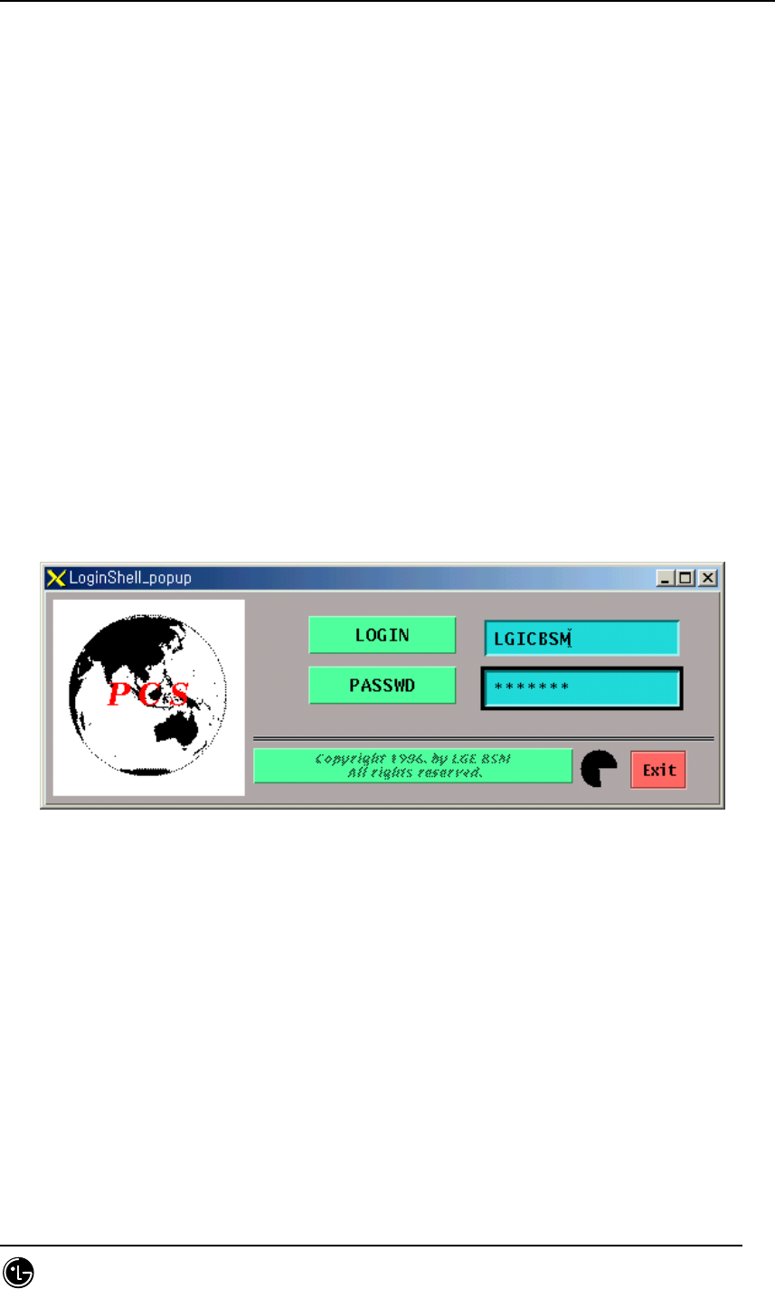
STAREX-IS BSM Manual
Page:132(877)
Issue:1.
0
SMD-011-PMA210
4. BSM Command
4.1. User Interface Command
4.1.1. User Management Command
4.1.1.1. System Log-in
In order to manage the system and perform the desired work, one has to log in to the
BSM system. Login can be achieved through ID and passwords given to each individual
user. In order to log in to BSM, INTERM should be performed. At this time, one has to
input ID in LOGIN on the window that is shown and put passwords in “PASSWD”. Once
the existing ID and the Passwords are input, it is changed to the state that can input
the command.
If one does not log in for a while or time expires, INTERM should be performed again.
Input the corresponding user ID in Command “LOGIN:”
Input the corresponding password in “PASSWORD:”.
Fig. 4.1-1 BSM System Login Window
4.1.1.2. LOG-OUT
When terminating the work in the BSM and then wanting to log in again as other ID, the
user has to log out of his/her ID first. Once he/she logs out of the system and does not
relog in, he/she cannot use the command any more.
After logout, the window for the command input disappears and it is not shown until
relog-in is done.
Command : LOG-OUT
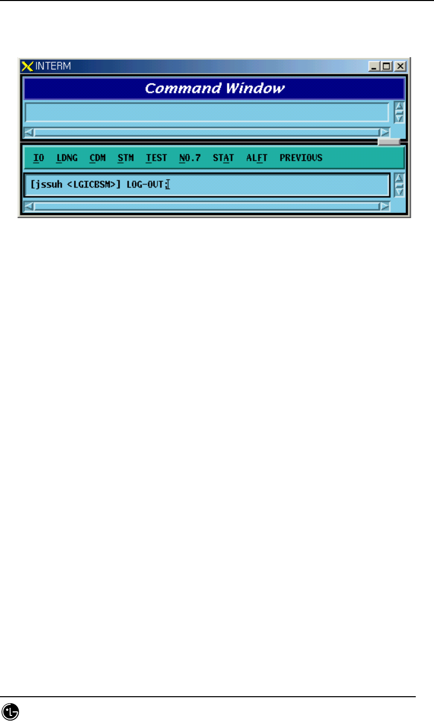
STAREX-IS BSM Manual
Page:133(877)
Issue:1.
0
SMD-011-PMA210
Input : LOG-OUT;
Output
Fig. 4.1-2 Log-out
4.1.1.3. User Addition
To operate and maintain the system, the user should register ID. The right to register
ID can be obtained from the manger in the first class. The newly registered ID is set
identically with initial passwords and ID and for security reason, the password for the
newly registered ID should be changed. The ID that is to be registered should be
original. That is, it should not be overlapped with existing ones. It can be registered as
the second or third class. ID should be within 15 letters.
Command : ADD-USR:USR=a, CLS=b;
a : User ID [ String ]
b : Class [Number 2 or 3 ]
Input : ADD-USER:USER=USER1,CLS=2;
Output
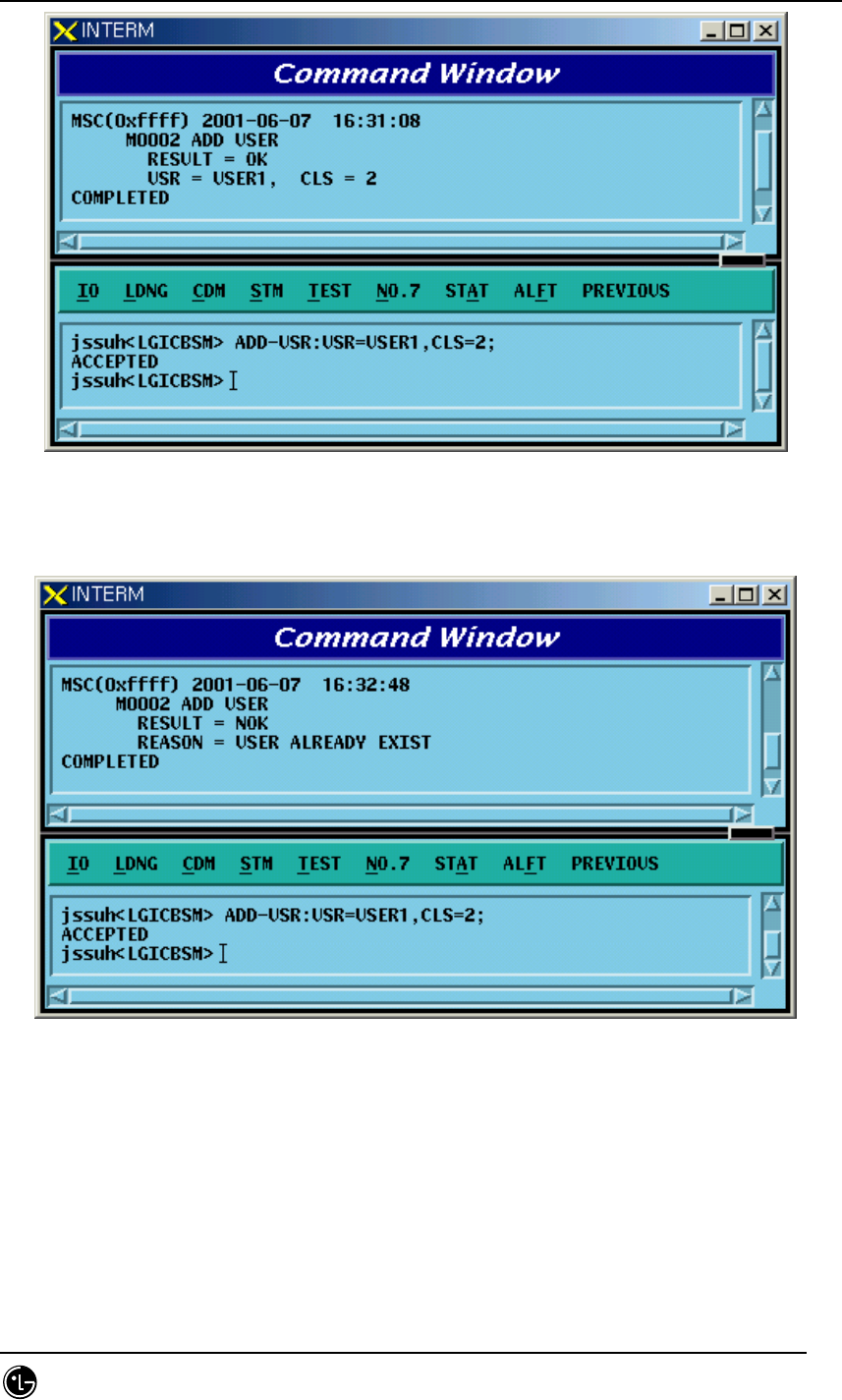
STAREX-IS BSM Manual
Page:134(877)
Issue:1.
0
SMD-011-PMA210
Fig. 4.1-3 User ID Register
When the ID exists already
Fig. 4.1-4 Errors When Registering User ID
4.1.1.4. User Deletion
Delete one user ID among the IDs that are no longer used or unnecessary ID.
Command : DEL-USR:USR=a;
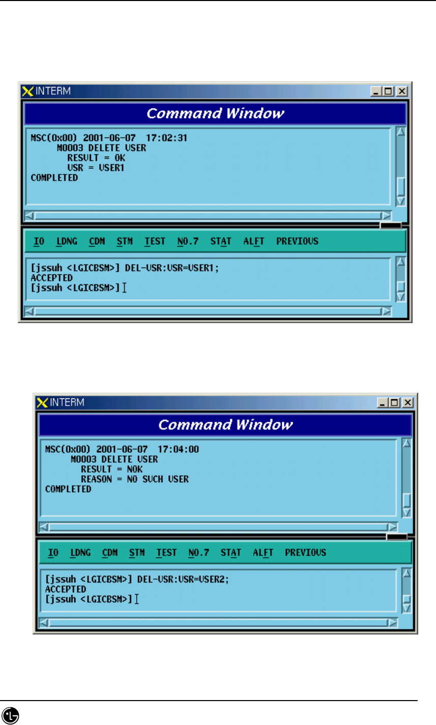
STAREX-IS BSM Manual
Page:135(877)
Issue:1.
0
SMD-011-PMA210
a : User ID to be deleted [ String ]
Input : DEL-USR:USR=USER1;
Output
Fig. 4.1-5 User ID Deletion
When deleting ID that does not exist
Fig. 4.1-6 Errors When Deleting User ID That Does Not Exist
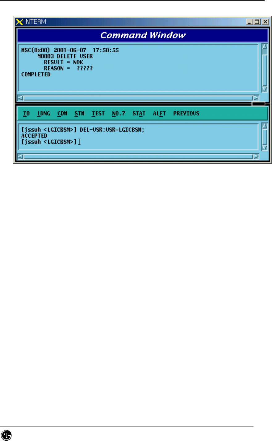
STAREX-IS BSM Manual
Page:136(877)
Issue:1.
0
SMD-011-PMA210
When deleting manager class ID
Fig. 4.1-7 Errors When Deleting the Manager Class ID
4.1.1.5. User Class Change
Broaden the range of the command or narrow it down by changing the use class of the
corresponding user.
Command CHG-USR-CLS:USR=a,CLS=b
a: User ID[String]
b: Class [2-3]
Input CHG-USR-CLS:USR=USER1,CLS=3;
Output
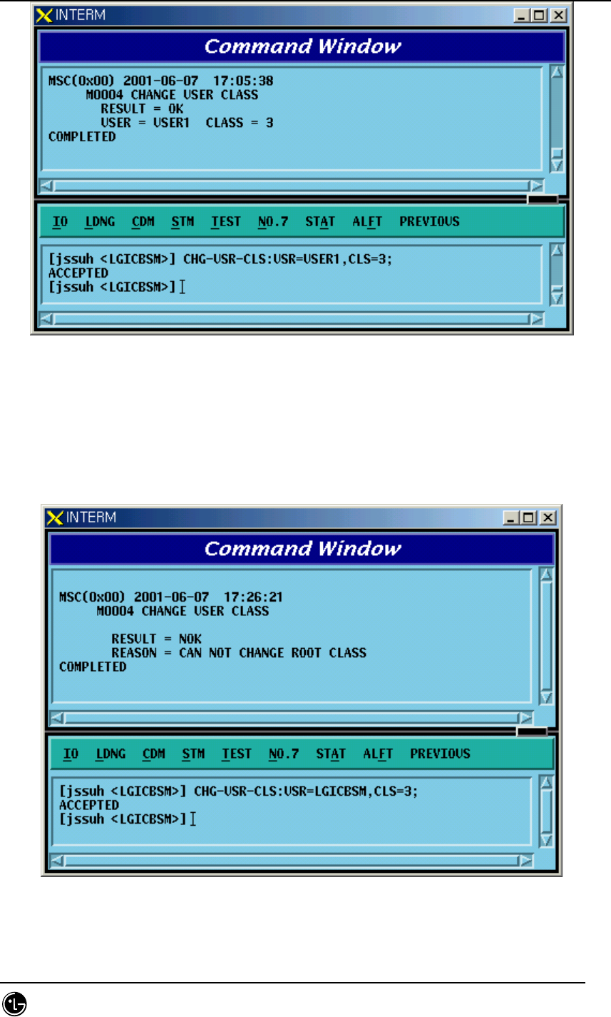
STAREX-IS BSM Manual
Page:137(877)
Issue:1.
0
SMD-011-PMA210
Fig. 4.1-8 User Class Change
When changing the use class of the manager
Fig. 4.1-9 Errors When Changing the Use Class of the Manager
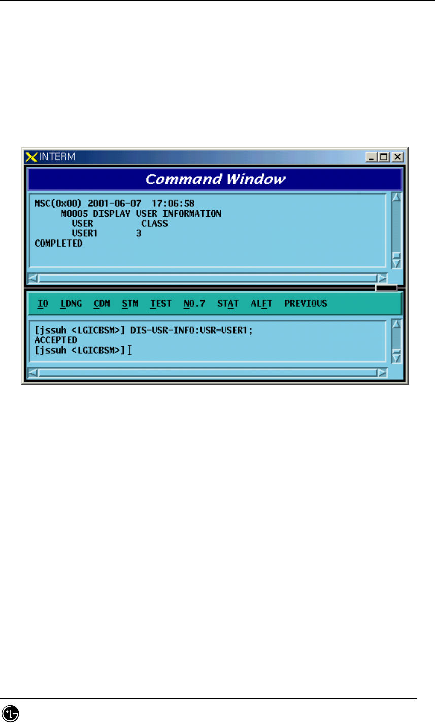
STAREX-IS BSM Manual
Page:138(877)
Issue:1.
0
SMD-011-PMA210
4.1.1.6. User Information Display
Display registered User ID and class.
Command DIS-USR-INFO[USR=a]
a: User ID[String]
Input CHG-USR-INFO:USR=USER1;
Output
Fig. 4.1-10 User Information Display
4.1.1.7. User Password Change
Change ID and Password in use. In particular, since the ID of the first time registered
user should be identical with the password, change the password as follows for
security reasons.
Command CHG-PWD
Input CHG-PWD
Output
Input the OLD PASSWORD and NEWPASSWORD one more time and check them.
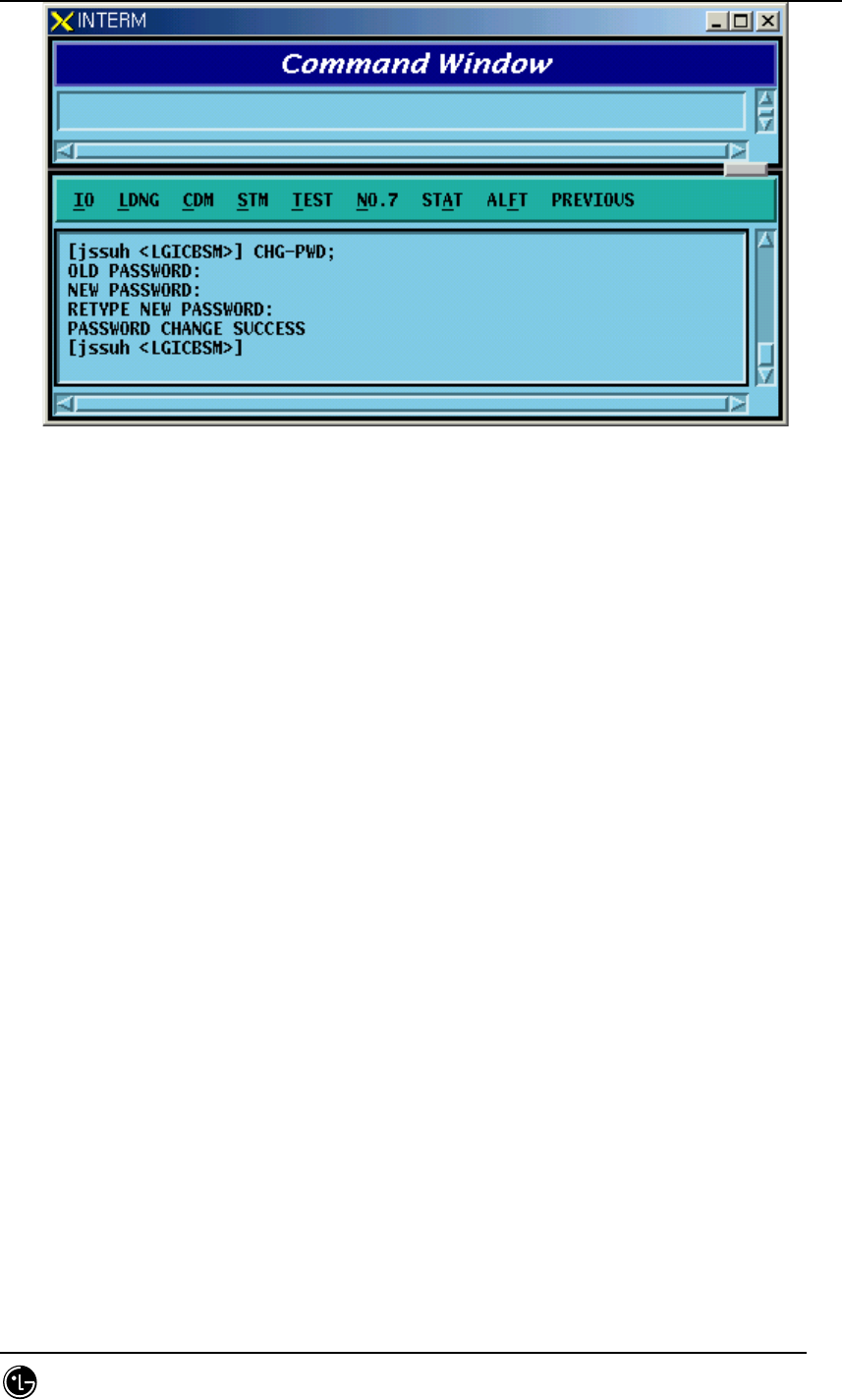
STAREX-IS BSM Manual
Page:139(877)
Issue:1.
0
SMD-011-PMA210
Fig. 4.1-11 User Password Change
4.1.2. Command Management Command
4.1.2.1. Command Class Modification
Modify the minimum class that can execute the registered command.
If the command class is n, one has to log in as ID that is more than n class to use this
command.
Command CHG-CMD-CLS:CRN=a,CLS=b
a : Command Reference Number [0~9999]
b : Class [1~3]
Input CHG-CMD-CLS:CRN=0300,CLS=1
Output
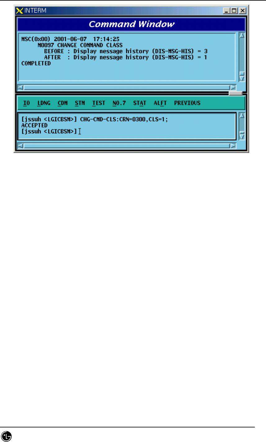
STAREX-IS BSM Manual
Page:140(877)
Issue:1.
0
SMD-011-PMA210
Fig. 4.1-12 Command Class Modification
4.1.2.2. Command Class Display
One can see the command of the corresponding class by designating the class that is
desired to be displayed.
Command DIS-CMD-CLS:CLS=a;
a : Class [1~3]
Input DIS-CMD-CLS:CLS=3;
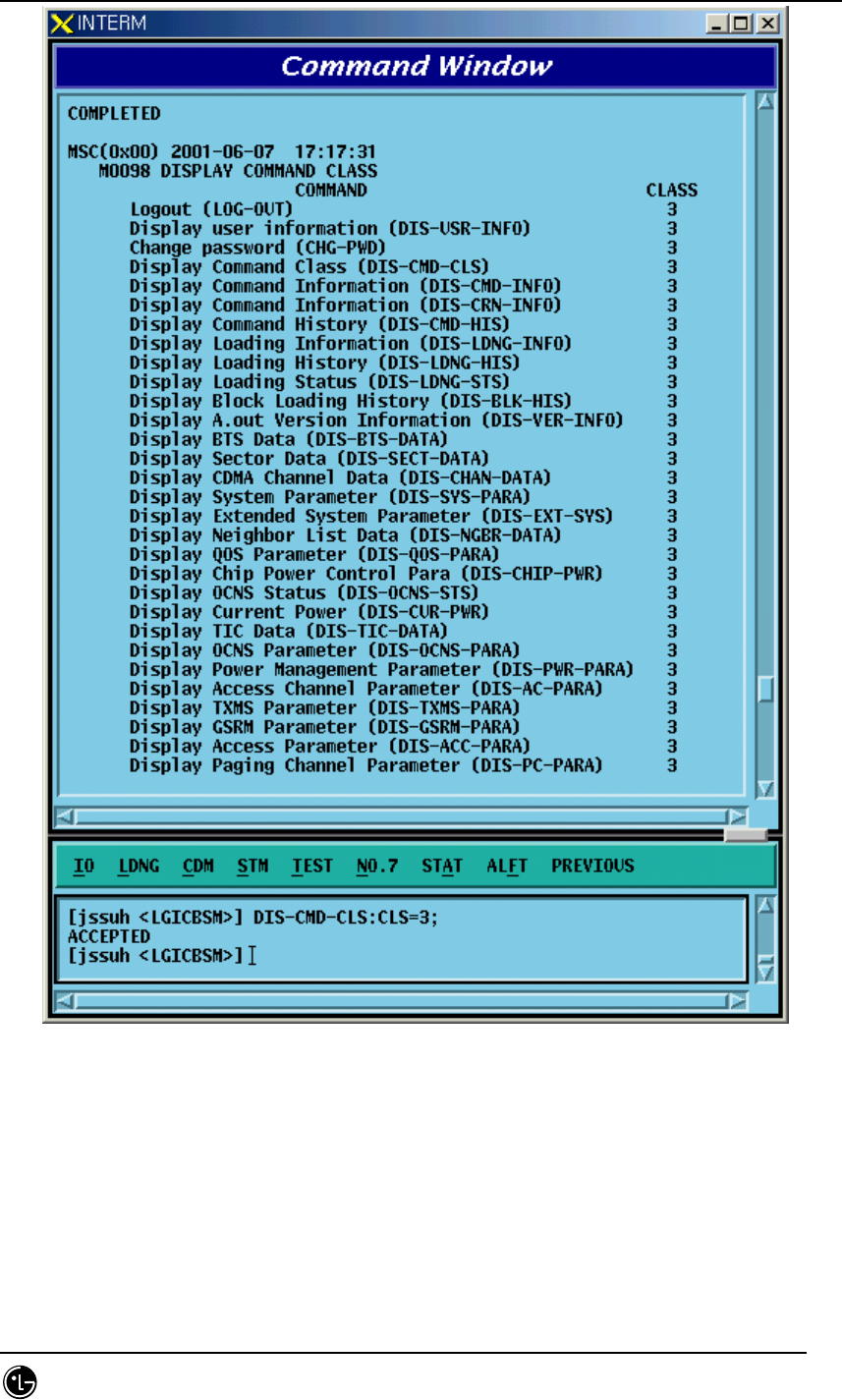
STAREX-IS BSM Manual
Page:141(877)
Issue:1.
0
SMD-011-PMA210
Fig. 4.1-13 Command Class Display
4.1.2.3. Command Information Display by Name
Display the syntax to use the information on the registered commands.
Command DIS-CMD-INFO:VERB=a
a : Command [Note : The command discriminator is determined to be &]
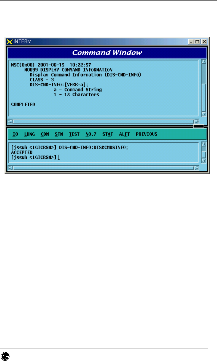
STAREX-IS BSM Manual
Page:142(877)
Issue:1.
0
SMD-011-PMA210
Input DIS-CMD-INFO:DIS&CMD&INFO;
Output
Fig. 4.1-14 Command Information Display by Name
4.1.2.4. Command Information by CRN
Display the command information by CRN which is designated for each command.
Command DIS-CRN-INFO:CRN=a
a : Command Reference Number [0~9999]
Input DIS-CRN-INFO:CRN=0200;
Output
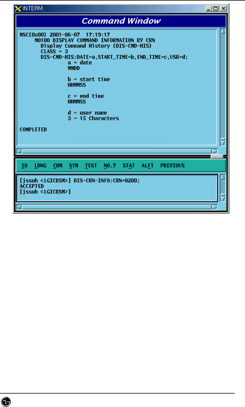
STAREX-IS BSM Manual
Page:143(877)
Issue:1.
0
SMD-011-PMA210
Fig. 4.1-15 Command Information Display by CRN
4.1.3. History Management Command
4.1.3.1. Command History Display
•Command DIS-CMD-HIS[:[DATE=a][,STM=b][,ETM=c][,USR=d]]
a : Date [MMDD]
MM : Month [1-12]
DD : Day [1-day last]
b : Start Time [HHMMSS]
HH : Hour [00-24]
MM : Min [00-60]
SS : Sec [00-60]
c : End Time [HHMMSS]
d : User ID [string]
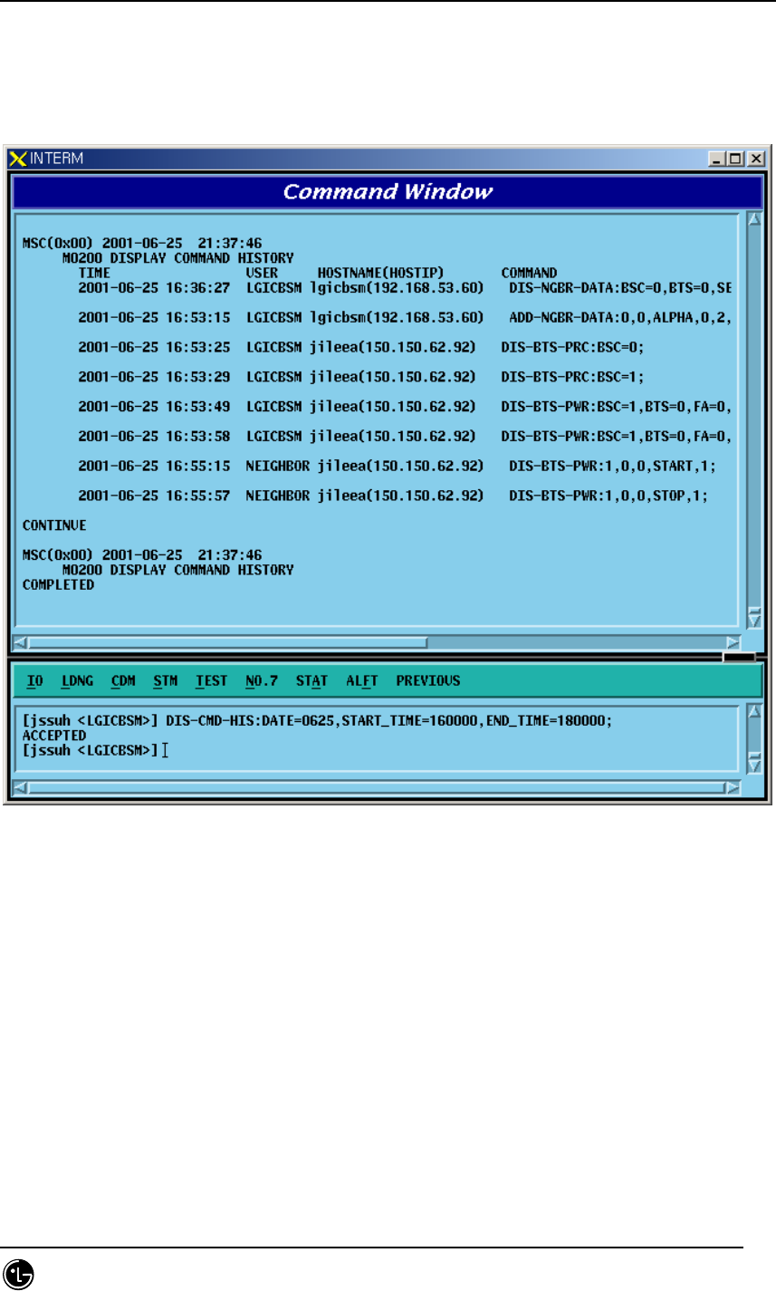
STAREX-IS BSM Manual
Page:144(877)
Issue:1.
0
SMD-011-PMA210
Input DIS-CMD-HIS:DATE=0625,STM=160000,ETM=180000
Output
Fig. 4.1-16 Command History Display
4.1.3.2. Message History Display
Command DIS-MSG-
HIS:TYPE=a,[DATE=b],[START_TIME=c],[END_TIME=d]
,[START_BSC=e],[END_BSC=f],[START_BTSGRP=g],
[END_BTSGRP=h] ,[START_BTSSUB=i],[END_BTSSUB=j],[PRN=k];
a : Message Type [SYS, MMC, STS, FLT, ALM]
SYS : system message
MMC : MMC command
STS : status message

STAREX-IS BSM Manual
Page:145(877)
Issue:1.
0
SMD-011-PMA210
FLT : fault message
ALM : alarm message
b : Date [MMDD]
MM : Month [1-12]
DD : Day [1-day last]
c : Start Time [HHMMSS]
HH : Hour [00-24]
MM : Min [00-60]
SS : Sec [00-60]
d : End Time [HHMMSS]
e : Start BSC number[0 ~ 127]
f : End BSC number[0 ~ 127]
g : Start BTS GRP number[0 ~ 47]
h : End BTS GRP number[0 ~ 47]
i : Start BTS SUB number[0 ~ 3]
j : End BTS SUB number[0 ~ 3]
k : Message number[0 ~ 9999]
Input DIS-MSG-HIS:TYPE=MMC,DATE=0625,START_TIME=140000,
END_TIME=150000, START_BSC=0, [START_BTSGRP=0;
Output
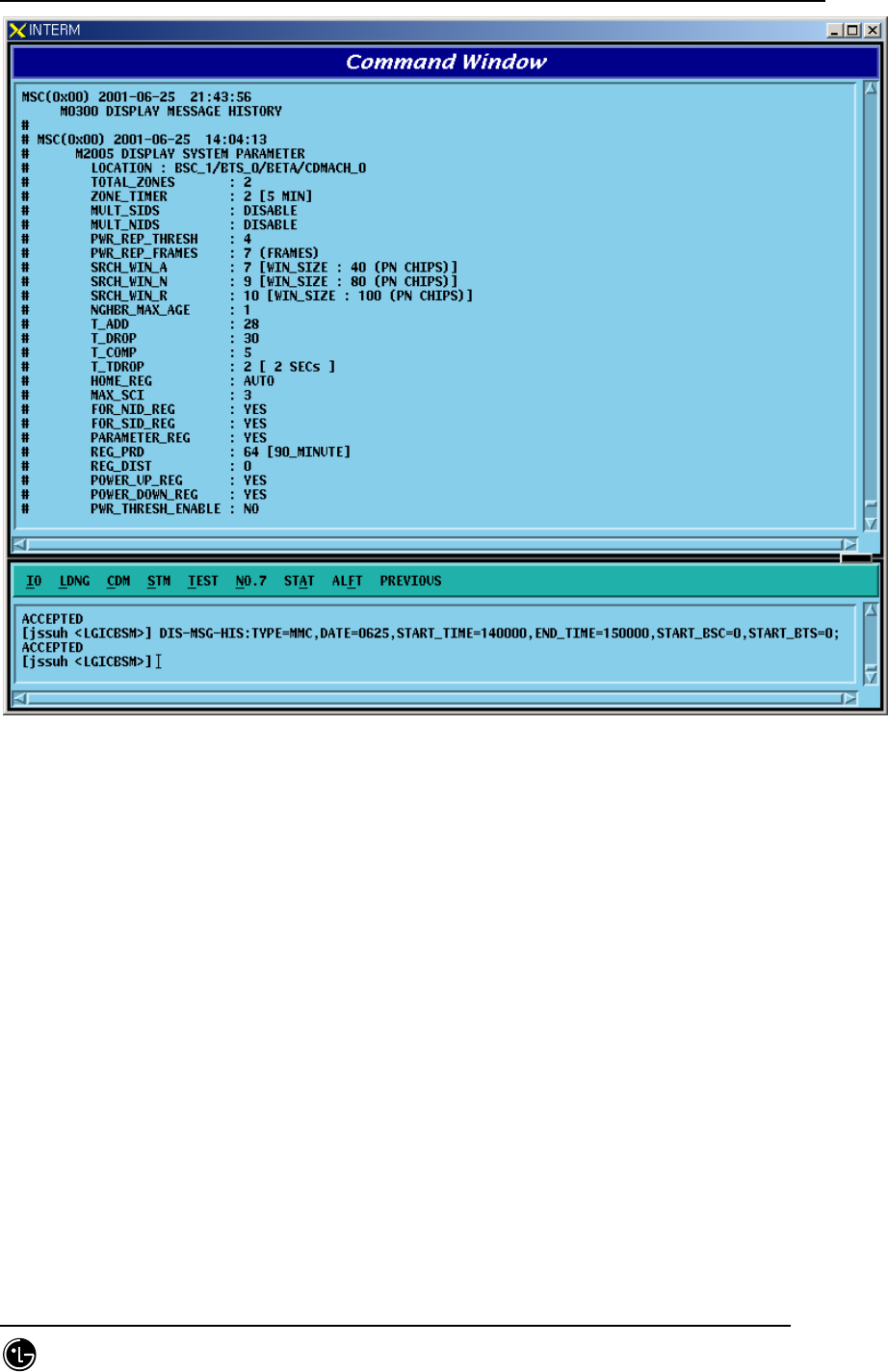
STAREX-IS BSM Manual
Page:146(877)
Issue:1.
0
SMD-011-PMA210
Fig. 4.1-17 Message History Display Start
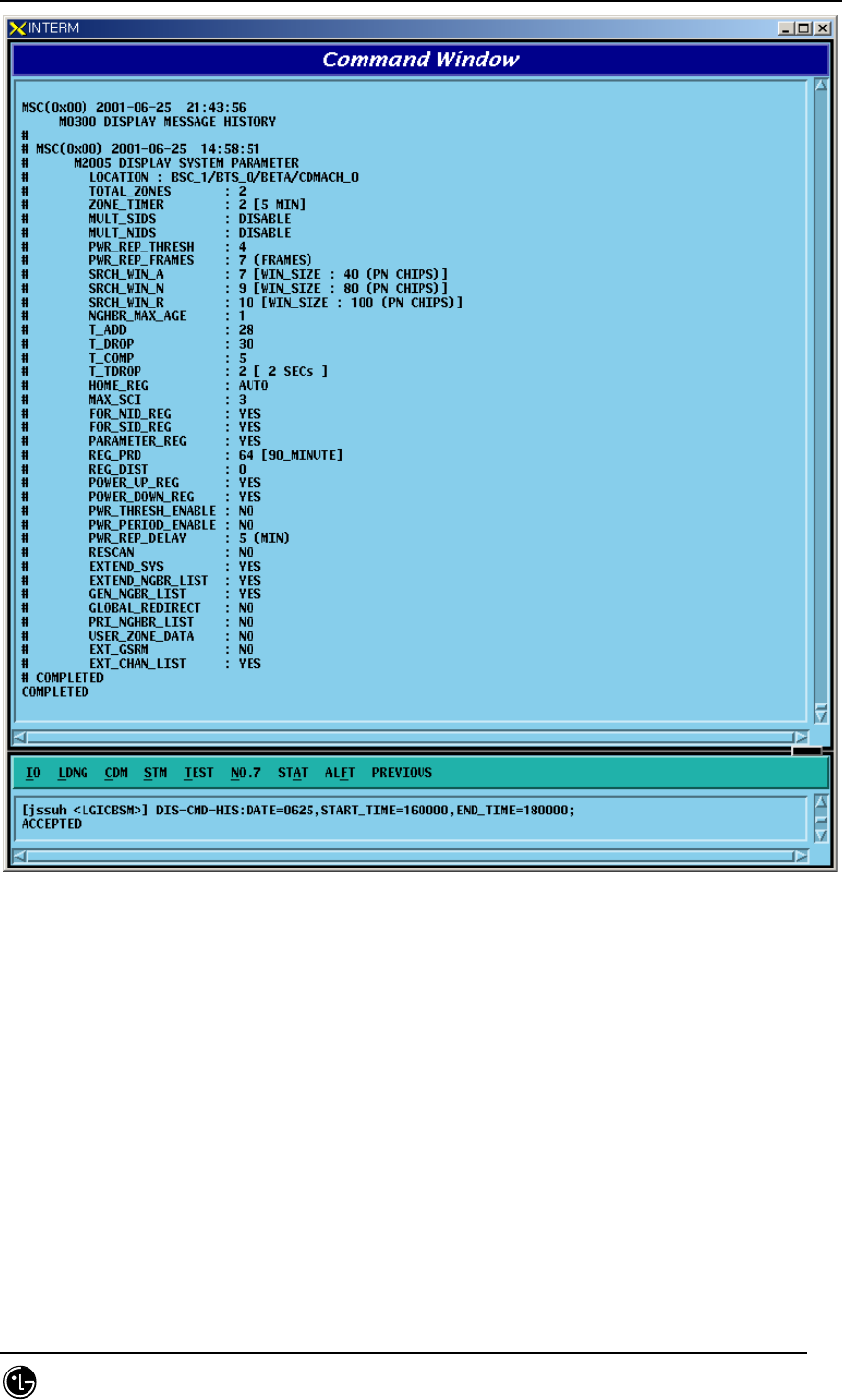
STAREX-IS BSM Manual
Page:147(877)
Issue:1.
0
SMD-011-PMA210
Fig. 4.1-18 Message History Display End

STAREX-IS BSM Manual
Page:148(877)
Issue:1.
0
SMD-011-PMA210
4.2. Loading Command
4.2.1. Loading Control Command
4.2.1.1. Block Loading (DOWN-BLK)
This command is used to download specific S/W blocks to target processors from BSM.
The target processors that can designate the block loading are as follows: CNP, PNP,
PCP, PMP, NCP, CCP, SCP, BSP, SMP, and VMP. This command is used to download
blocks that need subloading to the lower level processors of the designated target
processors.
Command : DOWN-BLK:[BSC=a,][BTS=b,]PROC=c,FLASH=d,BLK=e;
a : BSC ID [ Number 0~11 ]
b : BTS ID [ Number 0~47 ]
c : Processor Name [ CNP, PNP, PCP0, PCP1, PCP2, PMP0,
PMP1, PMP2, NCP, CCP, SCP, BSP,
SMP0,
SMP1, SMP2, SMP3, SMP4, VMP0, VMP1,
VMP2, VMP3, VMP4, VMP5, VMP6,
VMP7 ]
d : Whether to update the flash memory [ UPDATE or
MAINTAIN ]
e : Block Name [ String ]
Input : DOWN-BLK:BSC=1,PROC=CCP,FLASH=MAINTAIN,BLK=rcpuser;
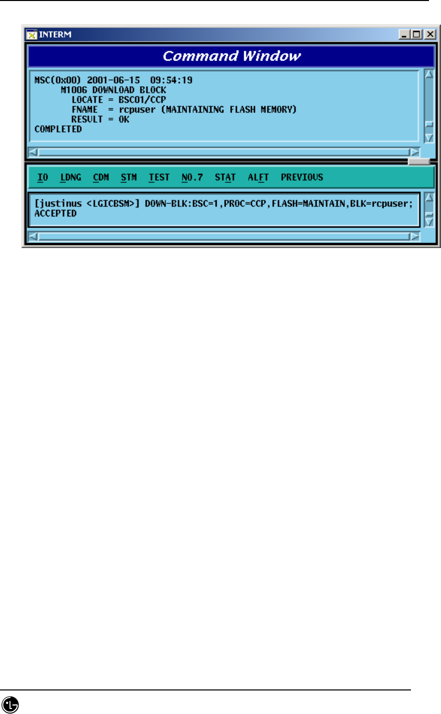
STAREX-IS BSM Manual
Page:149(877)
Issue:1.
0
SMD-011-PMA210
Output :
Fig. 4.2-1 Blocking Loading Performance Result
4.2.1.2. Activation Loading (ACT-BLK)
This command is used to download the specific S/W blocks from BSM to the target
processor and then to activate them. The target processors that can designate the
activation loading are CNP, PNP, PCP, PMP, NCP, CCP, SCP, BSP, ALP, SMP, and
VMP. This command is used to download S/W blocks that are operated in the target
processors and to replace blocks which are currently in operation by using the newly
downloaded blocks.
Command : ACT-BLK:[BSC=a,][BTS=b,]PROC=c,FLASH=d,
BLK1=e[,BLK2=e][,BLK3=e];
a : BSC ID [ Number 0~11 ]
b : BTS ID [ Number 0~47 ]
c : Processor Name[ CNP, PNP, PCP0, PCP1, PCP2, PMP0,
PMP1, PMP2, NCP, CCP, SCP, BSP,
ALP, SMP0, SMP1, SMP2, SMP3, SMP4,
VMP0, VMP1, VMP2, VMP3, VMP4,
VMP5,
VMP6, VMP7 ]
d : Whether to Update Flash Memory [ UPDATE or
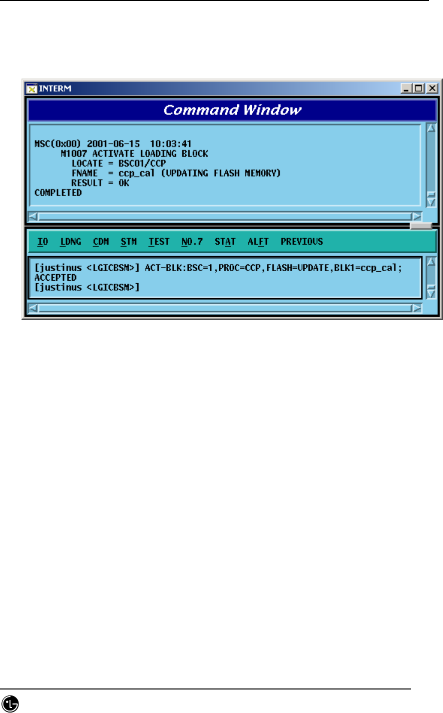
STAREX-IS BSM Manual
Page:150(877)
Issue:1.
0
SMD-011-PMA210
MAINTAIN ]
e : Block Name [ String ]
Input : ACT-BLK:BSC=1,PROC=CCP,FLASH=UPDATE,BLK=ccp_cal;
Output :
Fig. 4.2-2 Activation Loading Performance Result
4.2.1.3. Flash Memory Update (UPD-FLS)
The command to update Flash memory is used to designate memory update as
MAINTAIN in the block loading and activation loading and then to record the following:
1) the blocks that are downloaded as a result of the block loading and 2) activation
loading command results in the Flash Memory.
Command : UPD-FLS:[BSC=a,][BTS=b,]PROC=c ;
a : BSC ID [ Number 0~11 ]
b : BTS ID [ Number 0~47 ]
c : Processor Name [ CNP, PNP, PCP0, PCP1, PCP2, PMP0,
PMP1, PMP2, NCP, CCP, SCP, BSP,
ALP ]
Input : UPD-FLS:BSC=1,PROC=CCP;
Output :
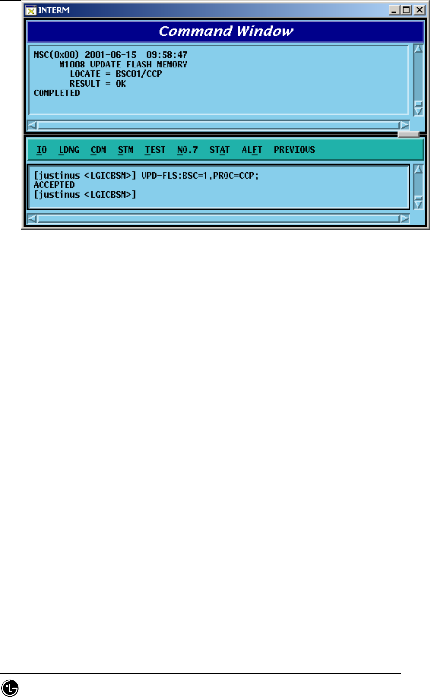
STAREX-IS BSM Manual
Page:151(877)
Issue:1.
0
SMD-011-PMA210
Fig. 4.2-3 Flash Memory Update Result
4.2.1.4. Processor Loading Request on the Standby Side (SBY-LDNG-
PRC)
It is the function that requests the loading to standby side of the processors. The
target processors that can perform the Standby loading should be duplicated and both
A and B sides should be normally operated. (If they are not duplicated or abnormal, the
Standby loading cannot be performed.)
The target processors that can request the processor loading on the standby side are
as follows: CNP, PNP, PCP, PMP, NCP, CCP, SCP, and BSP.
Command : SBY-LDNG-PRC:[BSC=a,][BTS=b,]PROC=c ;
a : BSC ID [ Number 0~11 ]
b : BTS ID [ Number 0~47 ]
c : Processor Name [ CNP, PNP, PCP0, PCP1, PCP2, PMP0,
PMP1, PMP2, NCP, CCP, SCP, BSP ]
4.2.1.5. Processor Switching-over (ACT-PRC)
The command to switch over the processors is switch over the Active Side of the
target processors which operate as NORM(OLD) and NORM(NEW) after performing
standby loading.

STAREX-IS BSM Manual
Page:152(877)
Issue:1.
0
SMD-011-PMA210
Command : ACT-PRC:[BSC=a,][BTS=b,]PROC=c ;
a : BSC ID [ Number 0~11 ]
b : BTS ID [ Number 0~47 ]
c : Processor Name [ CNP, PNP, PCP0, PCP1, PCP2, PMP0,
PMP1, PMP2, NCP, CCP, SCP, BSP ]
4.2.1.6. Processor Copy (COPY-PRC)
The command to copy processors which performed the standby loading and then
operate as NORM(OLD) and NORM(NEW) to the Block that received the Standby
loading.
Command : COPY-PRC:[BSC=a,][BTS=b,]PROC=c ;
a : BSC ID [ Number 0~11 ]
b : BTS ID [ Number 0~47 ]
c : Processor Name [ CNP, PNP, PCP0, PCP1, PCP2, PMP0,
PMP1, PMP2, NCP, CCP, SCP, BSP ]
4.2.1.7. Firmware Loading (LOAD-FIRM)
The command to load the firmware is used to download the firmware data to fuse to
the target processors or processors that serve as device servers.
Command : LOAD-FIRM :[BSC=a,] [BTS=b,] PROC_L1=c
[,PROC_L2=d], FILENAME=e;
a : BSC ID [ Number 0~11 ]
b : BTS ID [ Number 0~47 ]
c : Level 1 Processor [ CNP, PNP, PCP0, PCP1, PCP2, PMP0,
PMP1, PMP2, NCP, CCP, SCP, BSP ]
d : Level 2 Processor [ ASCA, ASIA0, ASIA1, ASIA2, ASIA3,
ENP,
CRP, PIP0, PIP1, PIP2, PIP3, PIP4, PIP5,
PIP6, PIP7, PIP8, PIP9, PIP10, ALP,
SMP0,
SMP1, SMP2, SMP3, SMP4, VMP0, VMP1,
VMP2, VMP3, VMP4, VMP5, VMP6,

STAREX-IS BSM Manual
Page:153(877)
Issue:1.
0
SMD-011-PMA210
VMP7,
LICA0, LICA1,LICA2 ]
e : Firmware Data File Name [ String ]
4.2.1.8. Firmware Update (UPD-FIRM)
After downloading the firmware data to fuse to target processor or processors that
serve as the device servers using the firmware loading command, it downloads or fuse
firmware data to target processors to devices using the firmware update command.
Command : UPD-FIRM : [BSC=a] [,BTS=b] ,PROC_L1=c [,PROC_L2=d]
[,PROC_L3=e] [,SIDE=f] ,FILENAME=g ,TYPE=h;
a : BSC ID [ Number 0~11 ]
b : BTS ID [ Number 0~47 ]
c : :Level 1 Processor [ CNP, PNP, PCP0, PCP1, PCP2, PMP0,
PMP1, PMP2, NCP, CCP, SCP, BSP ]
d : Level 2 Processor [ ASCA, ASIA_ALL, ASIA0, ASIA1,
ASIA2,
ASIA3, ENP, CRP, PIP_ALL, PIP0, PIP1,
PIP2, PIP3, PIP4, PIP5, PIP6, PIP7, PIP8,
PIP9, PIP10, ALP, SMP0, SMP1, SMP2,
SMP3, SMP4, VMP0, VMP1, VMP2,
VMP3,
VMP4, VMP5, VMP6, VMP7, LICA_ALL,
LICA0, LICA1, LICA2 ]
e : Level 3 Processor [ ALMA_ALL, ALMA0, ALMA1,
ALPA_ALL,
ALPA0_0, ALPA0_1, ALPA0_2, ALPA0_3,
ALPA0_4, ALPA1_0, ALPA1_1, ALPA1_2,
ALPA1_3, ALPA1_4, SLP_ALL, SLP0,
SLP1,
SLP2, SLP3, SLP4, SLP5, SLP6, SLP7,
SLP8,
SLP9, SLP10, SLP11, SLP12, SLP13,
SLP14,
SLP15, SLP16, SLP17, SLP18, SLP19,
VCP_ALL, VCP0, VCP1, VCP2, VCP3,

STAREX-IS BSM Manual
Page:154(877)
Issue:1.
0
SMD-011-PMA210
VCP4,
VCP5, VCP6, VCP7, VCP8, VCP9, VCP10,
VCP11, VCP12, VCP13, VCP14, VCP15 ]
f : Side Information [ A_SIDE, B_SIDE, BOTH ]
g : Firmware Data File Name [ String ]
h : Firmware Type [ BOOTER_FW, CPLD_FW ]
4.2.2. Loading Information Display Command
4.2.2.1. Loading Information Display (DIS-LDNG-INFO)
It is the function that displays the loading information of specific processor.
Command : DIS-LDNG-INFO:[BSC=a,][BTS=b,]PROC=c ;
a : BSC ID [ Number 0~11 ]
b : BTS ID [ Number 0~47 ]
c : Processor Name [ CNP, PNP, PCP0, PCP1, PCP2, PMP0,
PMP1, PMP2, NCP, CCP, SCP, BSP,
ALP, SMP0, SMP1, SMP2, SMP3, SMP4,
VMP0, VMP1, VMP2, VMP3, VMP4,
VMP5,
VMP6, VMP7, RCP0, RCP1, RCP2, RCP3,
RCP4, RCP5, RCP6, RCP7, RCP8, RCP9 ]
Input : DIS-LDNG-INFO:BSC=1,PROC=CCP;
Output :
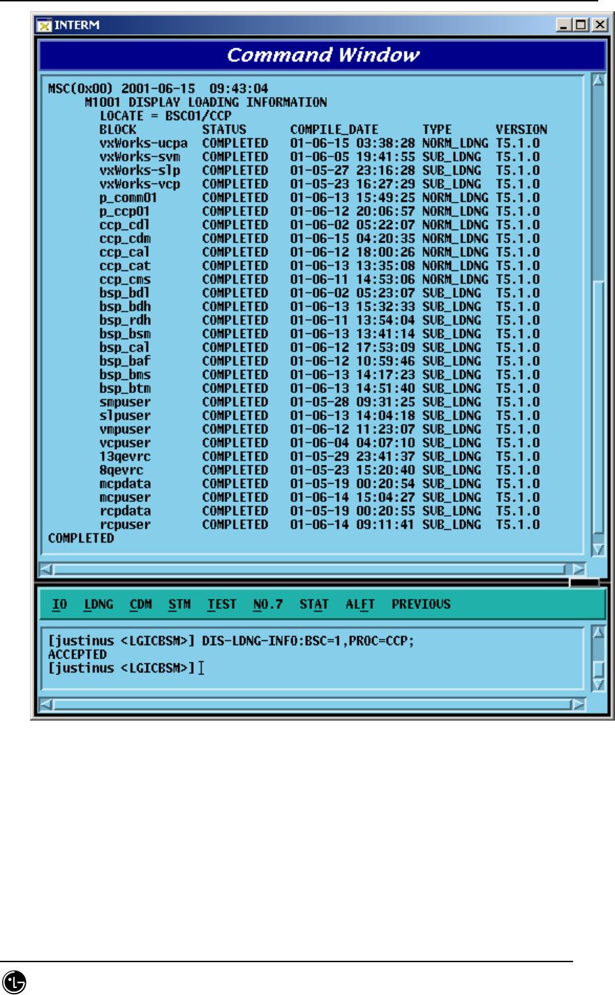
STAREX-IS BSM Manual
Page:155(877)
Issue:1.
0
SMD-011-PMA210
Fig. 4.2-4 Loading Information Display Command Execution Result
4.2.2.2. Loading History Display (DIS-LDNG-HIS)
It is the function that displayed up to 30 of the latest loading history of the specific
processor.

STAREX-IS BSM Manual
Page:156(877)
Issue:1.
0
SMD-011-PMA210
Command : DIS-LDNG-HIS:[BSC=a,][BTS=b,][PROC=c] ;
a : BSC ID [ Number 0~11 ]
b : BTS ID [ Number 0~47 ]
c : Processor Name (When deleting processor names, the
entire processors are displayed)
[ CNP, PNP, PCP0, PCP1, PCP2, PMP0,
PMP1, PMP2, NCP, CCP, SCP, BSP,
ALP, SMP0, SMP1, SMP2, SMP3, SMP4,
VMP0, VMP1, VMP2, VMP3, VMP4,
VMP5,
VMP6, VMP7, RCP0, RCP1, RCP2, RCP3,
RCP4, RCP5, RCP6, RCP7, RCP8, RCP9 ]
Input : DIS-LDNG-INFO:BSC=1,PROC=NCP;
Output :
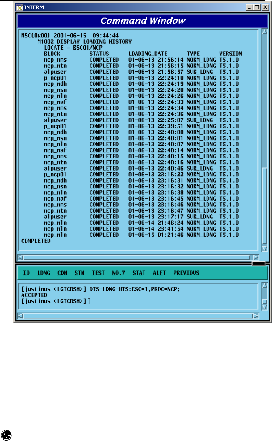
STAREX-IS BSM Manual
Page:157(877)
Issue:1.
0
SMD-011-PMA210
Fig. 4.2-5 Loading History Display Function Execution Result
4.2.2.3. Block Loading History Display (DIS-BLK-HIS)
It is the function that displays up to 30 of the latest block loading history of the
specific processors.

STAREX-IS BSM Manual
Page:158(877)
Issue:1.
0
SMD-011-PMA210
Command : DIS-BLK-HIS:[BSC=a,][BTS=b,]PROC=c ;
a : BSC ID [ Number 0~11 ]
b : BTS ID [ Number 0~47 ]
c : Processor Name [ CNP, PNP, PCP0, PCP1, PCP2, PMP0,
PMP1, PMP2, NCP, CCP, SCP, BSP,
SMP0,
SMP1, SMP2, SMP3, SMP4, VMP0, VMP1,
VMP2,VMP3,VMP4,VMP5,VMP6,VMP7 ]
Input : DIS-LDNG-INFO:BSC=1,BTS=0,PROC=BSP;
Output :
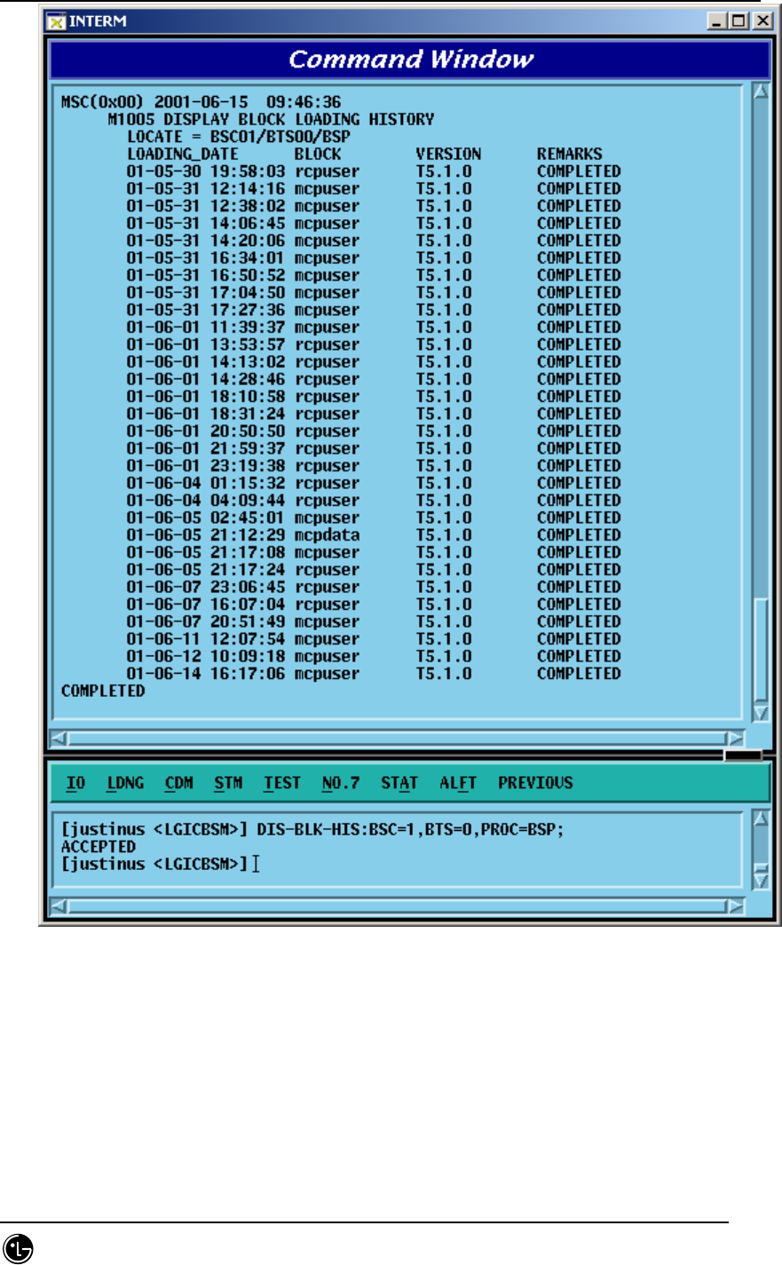
STAREX-IS BSM Manual
Page:159(877)
Issue:1.
0
SMD-011-PMA210
Fig. 4.2-6 Block Loading History Display Result
4.2.2.4. Loading State Display (DIS-LDNG-STS)
It is the function that displays the information on the processor that is performing
downloading.
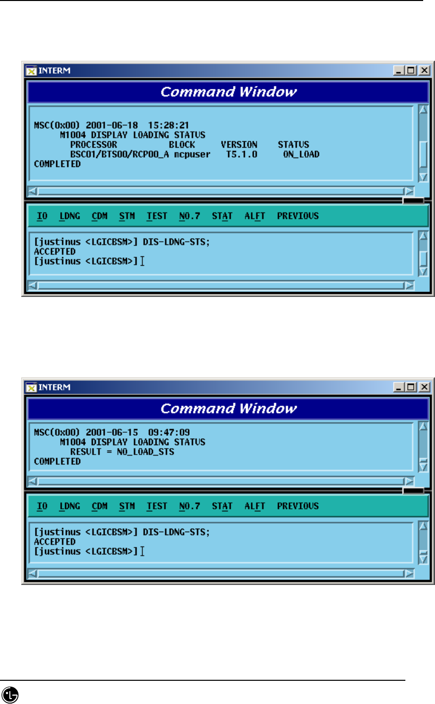
STAREX-IS BSM Manual
Page:160(877)
Issue:1.
0
SMD-011-PMA210
Command : DIS-LDNG-STS;
Input : DIS-LDNG-STS;
Output :
Fig. 4.2-7 Loading State Display Command Execution Result (When there is a
processor that is performing loading)
Fig. 4.2-8 Loading State Display Command Execution Result (When there is no
processor that is performing loading)

STAREX-IS BSM Manual
Page:161(877)
Issue:1.
0
SMD-011-PMA210
4.2.2.5. a.out Version Information Display (DIS-VER-INFO)
The command to display a.out version information is used to check the S/W block
version that is downloaded from the BSM loading directory or target processor.
The target processors that can designate are as follows: BSM, CNP, PNP, PCP, PMP,
NCP, CCP, SCP, BSP, ALP, SMP, VMP, and RCP.
Command : DIS-VER-INFO:[BSC=a,][BTS=b,]PROC=c[,FILENAME=d];
a : BSC ID [ Number 0~11 ]
b : BTS ID [ Number 0~47 ]
c : Processor Name [ BSM,CNP,PNP,PCP0,PCP1,PCP2,PMP0,
PMP1, PMP2, NCP, CCP, SCP, BSP, ALP,
SMP0, SMP1, SMP2, SMP3, SMP4, VMP0,
VMP1, VMP2, VMP3, VMP4, VMP5,
VMP6,
VMP7, RCP0, RCP1, RCP2, RCP3, RCP4,
RCP5, RCP6, RCP7, RCP8, RCP9 ]
d : File Name [ String ]
Input : DIS-VER-INFO:PROC=BSM,FILENAME=ccp_cdl;
DIS-VER-INFO:BSC=1,PROC=CCP,FILENAME=ccp_cdl;
Output :
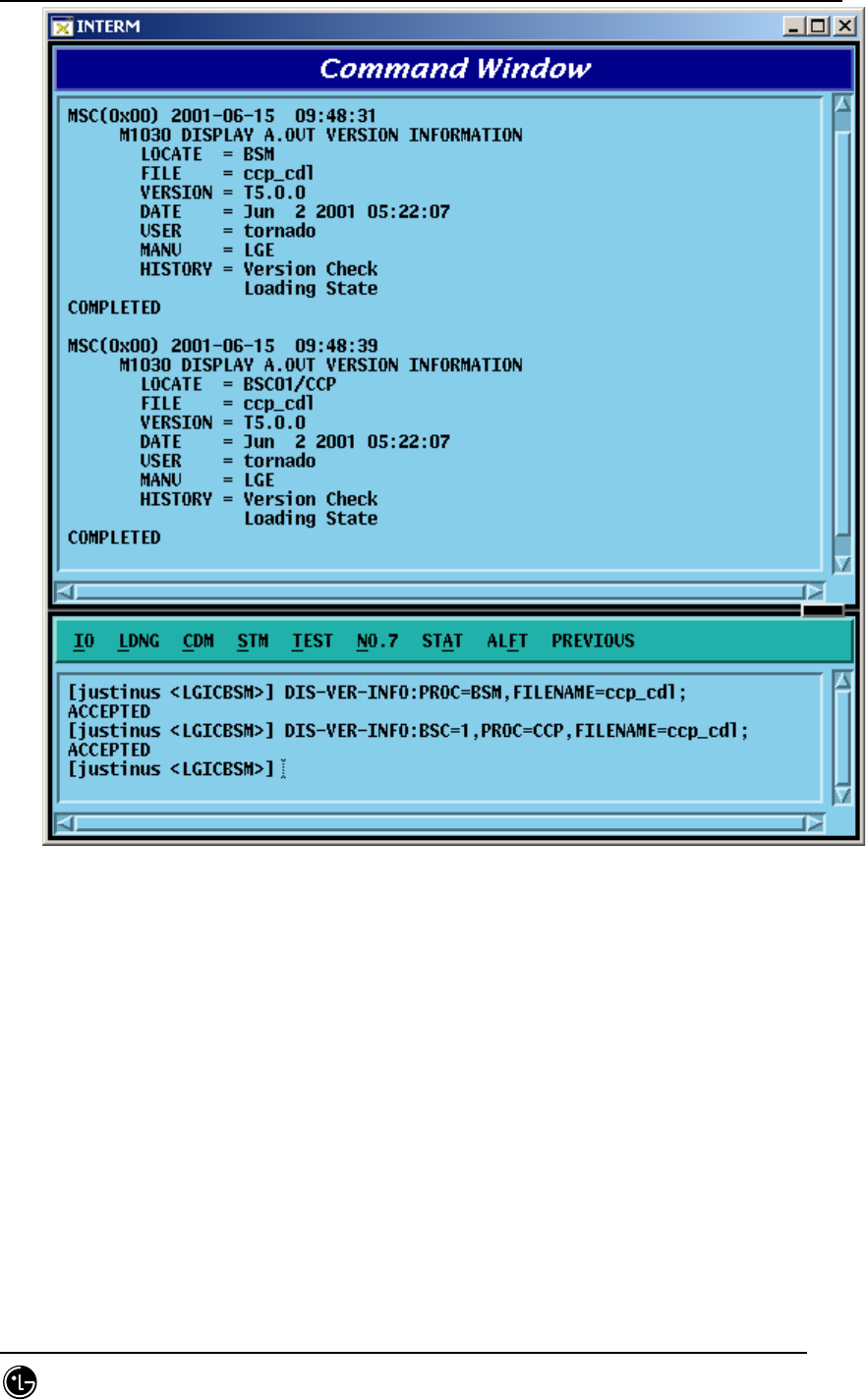
STAREX-IS BSM Manual
Page:162(877)
Issue:1.
0
SMD-011-PMA210
Fig. 4.2-9 Version Information Display Command Execution Result

STAREX-IS BSM Manual
Page:163(877)
Issue:1.
0
SMD-011-PMA210
4.3. Configuration Command
During the initialization, BTS and BSC download PDL (Programmable Loading Data)
that contain the configuration and parameter information as well as the OS and
Application.
This section describes the commands that help the user to manage the following
efficiently and variably by displaying PLD and changing them online: BTS and BSC
configuration, the parameter information, and the network configuration information. In
particular, the system’s flexibility is maximized by enabling BTS, Sector, FA, etc to be
expanded by the parameter input by the user without any additional data.
4.3.1. Parameter Information Display Command
(Display_Parameter_Information_1)
As a command that is used to inquire the parameter information that is currently stored
in the PLD, its results are displayed on the OUTPUT WINDOW.
Table 1-1 Parameter Information Display Command I
DIS-BTS-DATA BSC, BTS BTS DATA verification
DIS-SECT-DATA BSC, BTS, SECT SECTOR DATA verification
DIS-CHAN-DATA BSC, BTS, CDMACH CDMA CHANNEL DATA
verification
DIS-SYS-PARA BSC, BTS, SECT, CDMACH SYSTEM PARAMETER verification
DIS-EXT-SYS BSC, BTS, SECT, CDMACH EXTENDED SYSTEM
PARAMETER verification
DIS-NGBR-DATA BSC, BTS, SECT Neighbor cell information
verification
DIS-QOS-PARA BSC, BTS QOS verification
DIS-CHIP-PWR BSC, BTS CHIP power control parameter
verification
DIS-TIC-DATA BSC, BTS, SECT, CDMACH TIC DATA verification
DIS-SECT-CHAN BSC, BTS, SECT, CDMACH SYSTEM SECTOR CDMA
CHANNEL PARAMETER

STAREX-IS BSM Manual
Page:164(877)
Issue:1.
0
SMD-011-PMA210
verification
DIS-PWR-PARA BSC, BTS, SECT, CDMACH Power control parameter
information display
DIS-AC-PARA BSC, BTS, SECT,
CDMACH, PC, AC
ACCESS CHANNEL PARAMETER
verification
DIS-TXMS-PARA BSC, BTS, SECT, CDMACH TXMS PARAMETERS verification
DIS-GSRM-PARA BSC, BTS, SECT GSRM message verification
DIS-ACC-PARA BSC, BTS, SECT,
CDMACH, PC
ACCESS PARAMETER MESSAGE
verification
DIS-PC-PARA BSC, BTS, SECT,
CDMACH, PC
PAGING CHANNEL parameter
information verification
DIS-PICH-PARA BSC, BTS, SECT, CDMACH PILOT CHANNEL parameter
information verification
DIS-SC-PARA BSC, BTS, SECT, CDMACH SYNC CHANNEL PARAMETER
verification
DIS-QPC-PARA BSC, BTS, SECT,
CDMACH, QPC
QUICK PAGING CHANNEL
parameter information verification
DIS-BCON-PARA BSC, BTS, SECT
HOPPING PILOT BEACON
CHANNEL parameter information
verification
DIS-BTS-DATA BSC, BTS BTS DATA verification
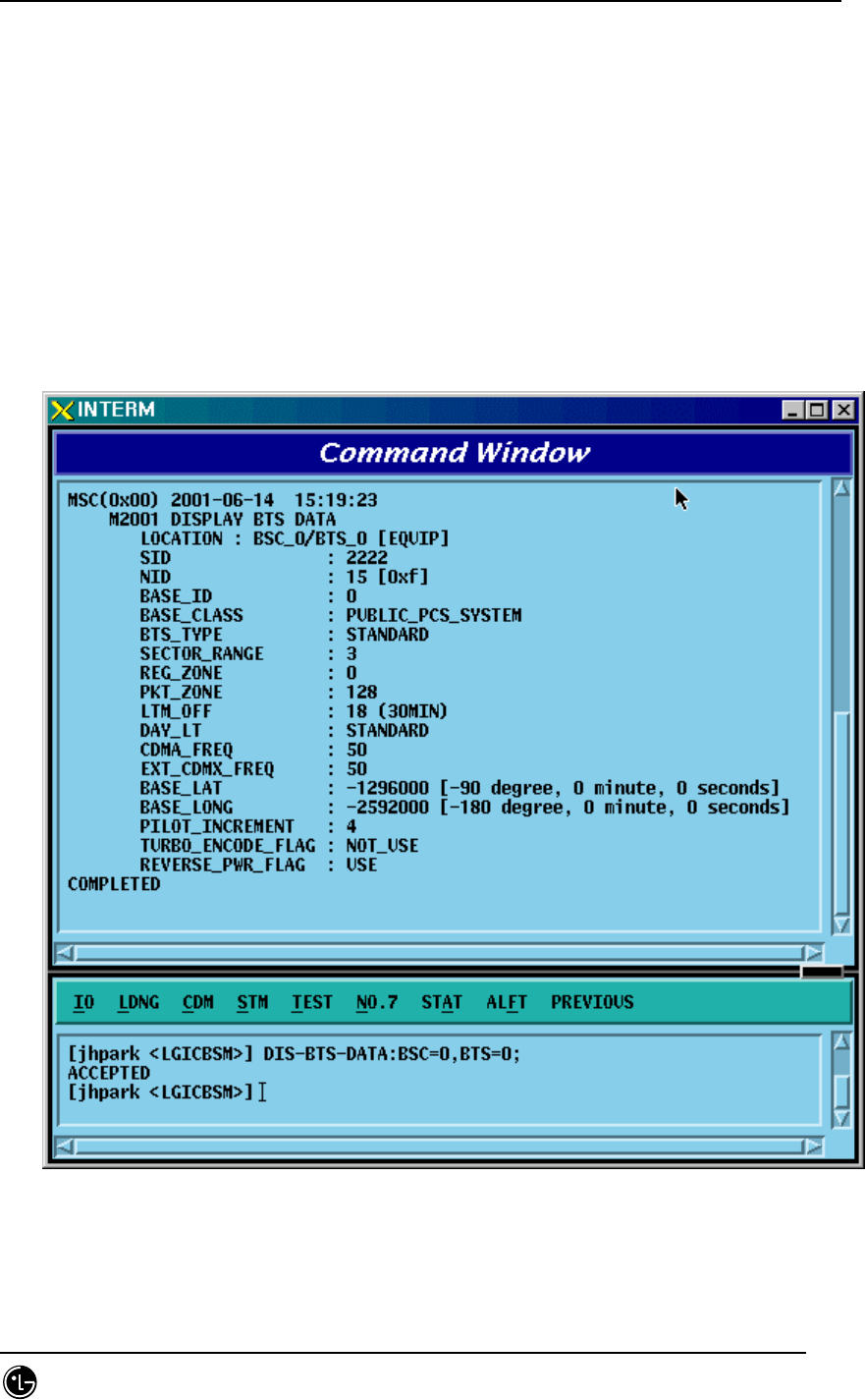
STAREX-IS BSM Manual
Page:165(877)
Issue:1.
0
SMD-011-PMA210
4.3.1.1. BTS Parameter Information Display
The BTS parameters are composed of data that are used to manage the BTS and both
BTS and BSC refer to this information.
• Command DIS-BTS-DATA:BSC=a,BTS_GRP=b,BTS_SUB=c;
a : BSC Number (0 ~ 11)
b : BTS Number (0 ~ 47)
c : BTS Sub Number (0 ~ 3)
• Input DIS-BTS-DATA:BSC=0,BTS_GRP=2,BTS_SUB=0;
• Output
Fig. 4.3-1 BTS Parameter Display
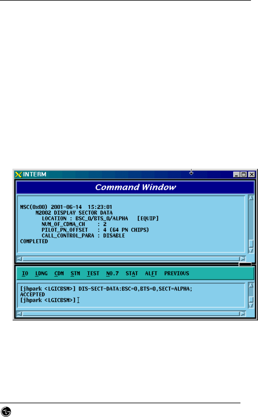
STAREX-IS BSM Manual
Page:166(877)
Issue:1.
0
SMD-011-PMA210
4.3.1.2. Sector Parameter Information Display
The BTS can be divided into 1~3 sectors to accommodate more subscribers. The
sector parameter information is composed of the information on each sector in BTS
and both BTS and BSC refer to this information. The user can inquire the data by BTS
Group, BTS Sub, and sector.
• Command DIS-SECT-DATA:BSC=a[,BTS_GRP=b][,BTS_SUB=c][,SECT=d];
a : BSC Number (0 ~ 11)
b : BTS Number (0 ~ 47)
c : BTS Sub Number (0 ~ 3)
d : Sector Number (ALPHA/BETA/GAMMA)
• Input DIS-SECT-DATA:BSC=0,BTS=0,SECT=ALPHA;
• Output
Fig. 4.3-2 Sector Parameter Information Display
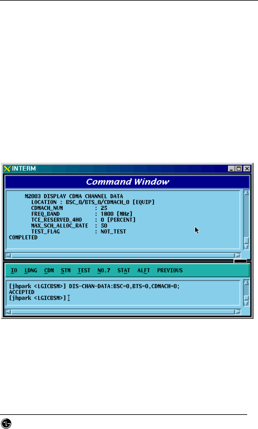
STAREX-IS BSM Manual
Page:167(877)
Issue:1.
0
SMD-011-PMA210
4.3.1.3. CDMA Channel Parameter Information Display
The following command is used to display parameter information such as bandwidth of
each CDMA channel, CDMA channel number, spare channel rate for Handoff(or
Handover). This information is referred by both BTS and BSC.
• Command DIS-CHAN-DATA:BSC=a,BTS_GRP=b,BTS_SUB=c[,CDMACH=c];
a : BSC Number (0 ~ 11)
b : BTS Number (0 ~ 47)
c : BTS Sub Number(0 ~ 3)
d : CDMA Channel Number (0 ~ 7)
• Input DIS-CHAN-DATA:BSC=0,BTS_GRP=2,BTS_SUB=0;
• Output
Fig. 4.3-3 CDMA Channel Parameter Information Display

STAREX-IS BSM Manual
Page:168(877)
Issue:1.
0
SMD-011-PMA210
4.3.1.4. System Parameter Message Display
As an Overhead message that is transmitted from BTS to MS through the paging
channel, the System Parameter Message contains the information to be used for the
call processing, handoff procedures, registration, etc. The information is checked by
using the following command and referred by both BTS and BSC.
• Command DIS-SYS-PARA:BSC=a,BTS_GRP=b,BTS_SUB=c,SECT=d,CDMACH=e;
a : BSC Number (0 ~ 11)
b : BTS Number (0 ~ 47)
c : BTS Sub Number (0 ~ 3)
d : Sector Number (ALPHA/BETA/GAMMA)
e : CDMA Channel Number (0 ~ 7)
• Input DIS-SYS-PARA:BSC=0,BTS_GRP=2,BTS_SUB=0,SECT=ALPHA,CDMACH=0;
• Output

STAREX-IS BSM Manual
Page:169(877)
Issue:1.
0
SMD-011-PMA210
Fig. 4.3-4 System Parameter Message Display

STAREX-IS BSM Manual
Page:170(877)
Issue:1.
0
SMD-011-PMA210
4.3.1.5. Extended System Parameter Message Display
As an overhead message that is transmitted from the BTS to MA through the paging
channel, the Extended System Parameter Message is referred by BTS and BSC.
• Command DIS-EXT-SYS:BSC=a,BTS_GRP=b,BTS_SUB=c;
a : BSC Number (0 ~ 11)
b : BTS Number (0 ~ 47)
c : BTS Sub Number (0 ~ 3)
• Input DIS-EXT-SYS:BSC=0,BTS_GRP=2,BTS_SUB=0;
• Output
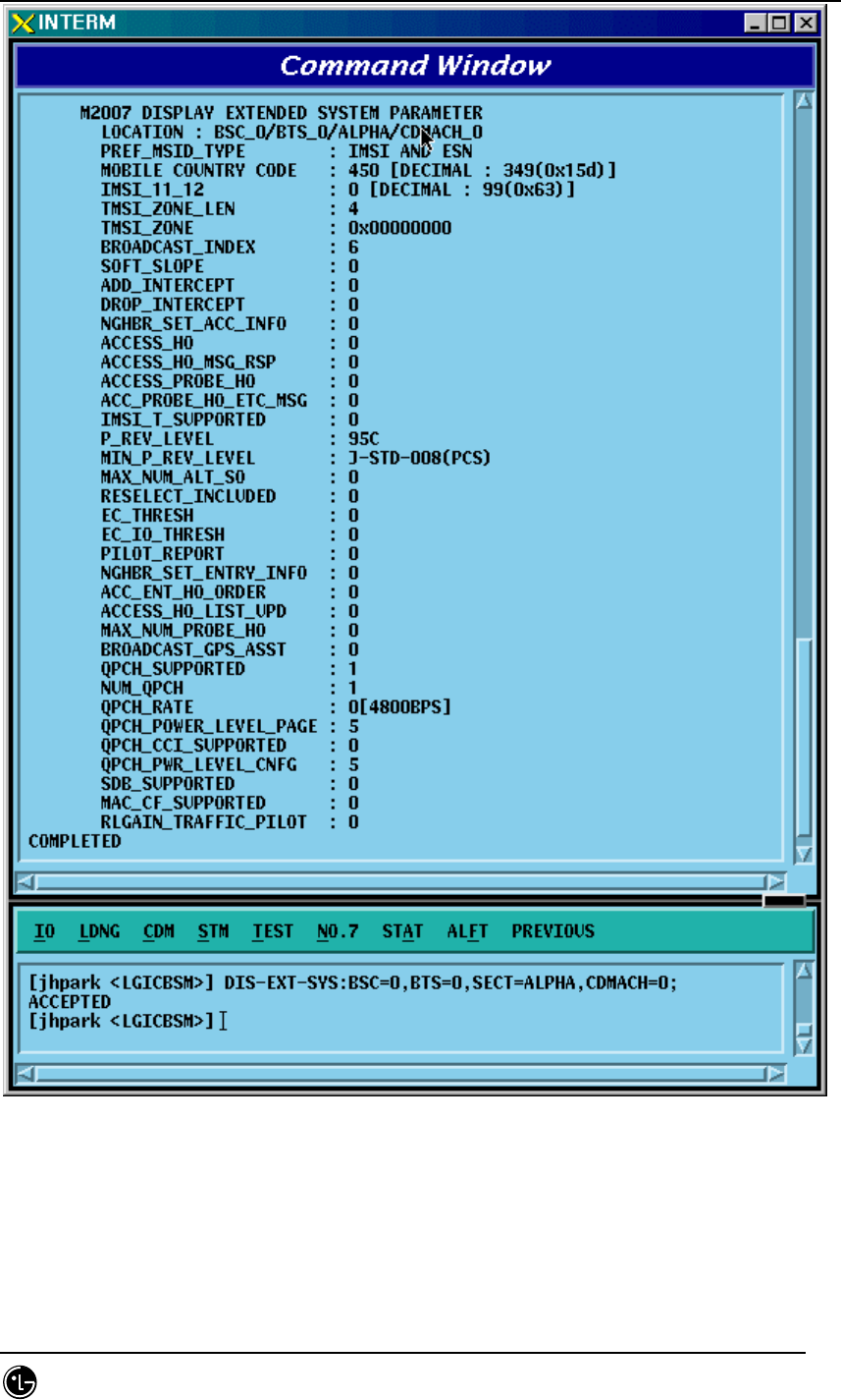
STAREX-IS BSM Manual
Page:171(877)
Issue:1.
0
SMD-011-PMA210
Fig. 4.3-5 Extended System Parameter Message Display

STAREX-IS BSM Manual
Page:172(877)
Issue:1.
0
SMD-011-PMA210
4.3.1.6. Neighbor List Parameter Information Display
Neighbor list refers to a set of the information on neighbor sectors. Each sector can
have up to 20 neighbor lists. When the MS, which is busy or idle, moves to other
sectors, it has to switch over a call (this is called Handoff or Handover). At this time,
handoff is carried out in reference to the neighbor list. The neighbor list is referred by
BTS and BSC and can be inquired by using the following command:
• Command DIS-NGBR-DATA:BSC=aa,BTS_GRP=b[,BTS_SUB=c][,SECT=c];
a : BSC Number (0 ~ 11)
b : BTS Number (0 ~ 47)
c : BTS Sub Number (0 ~ 3)
d : Sector Number (ALPHA/BETA/GAMMA)
• Input DIS-NGBR-DATA:BSC=0,BTS_GROUP=2,BTS_SUB=0;
• Output
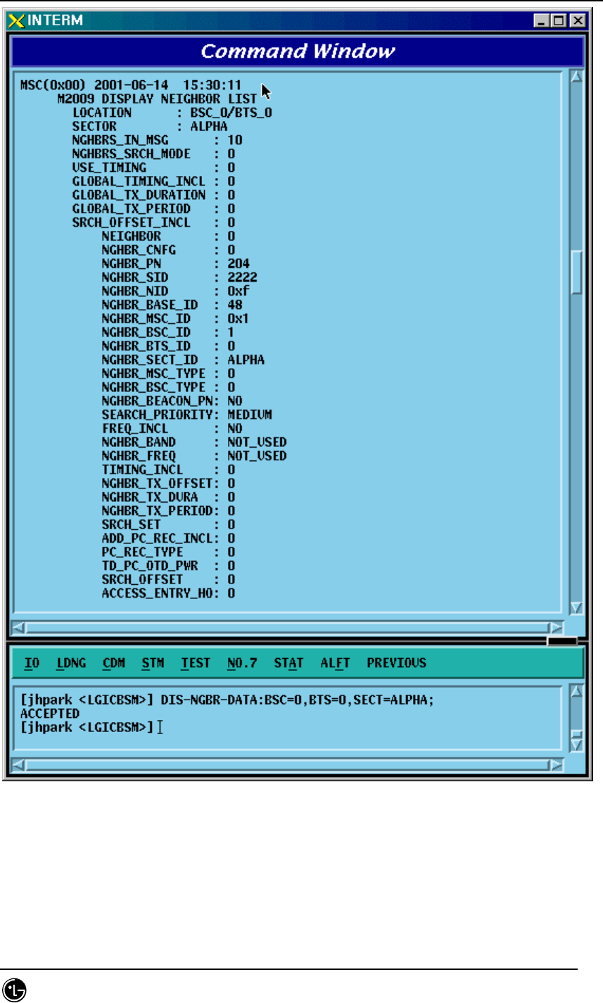
STAREX-IS BSM Manual
Page:173(877)
Issue:1.
0
SMD-011-PMA210
Fig. 4.3-6 Neighbor List Parameter Information Display
STAREX-IS BSM Manual
Page:174(877)
Issue:1.
0
SMD-011-PMA210
4.3.1.7. BTS QOS(Quality Of Service) Display
• Command DIS-QOS-PARA:BSC=a,BT=b;
a : BSC Number (0 ~ 11)
b : BTS Number (0 ~ 47)
• Input DIS-QOS-PARA:BSC=0,BTS=0;
• Output
Fig. 4.3-7 BTS QOS(Quality Of Service) Display
STAREX-IS BSM Manual
Page:175(877)
Issue:1.
0
SMD-011-PMA210
4.3.1.8. CHIP Power Control Parameter Display
• Command DIS-CHIP-PWR:BSC=a,BTS=b;
a : BSC Number (0 ~ 11)
b : BTS Number (0 ~ 47)
• Input DIS-CHIP-PWR:BSC=0,BTS=0;
• Output
Fig. 4.3-8 Display of Parameter that Controls CHIP Power
STAREX-IS BSM Manual
Page:176(877)
Issue:1.
0
SMD-011-PMA210
4.3.1.9. OCNS State Display
Input the following commands to display transmit values, the parameter information
used by BTS:
• Command DIS-OCNS-STS:BSC=a,BTS=b;
a : BSC Number (0 ~ 11)
b : BTS Number (0 ~ 47)
• Input DIS-OCNS-STS:BSC=0,BTS=0;
• Output
Fig. 4.3-9 OCNS State Display
STAREX-IS BSM Manual
Page:177(877)
Issue:1.
0
SMD-011-PMA210
4.3.1.10. Current Power Control Display
• Command DIS-CUR-PWR:BSC=a,BTS=b, SECT=c, CDMACH=d;
a : BSC Number (0 ~ 11)
b : BTS Number (0 ~ 47)
c: SECT
d: CDMACH
• Input DIS-CUR-PWR:BSC=0,BTS=0,SECT=ALPHA,CDMACH=0;
• Output
Fig. 4.3-10 Current Power Control Display
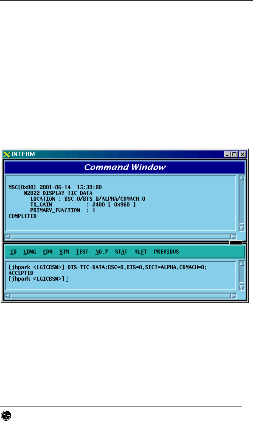
STAREX-IS BSM Manual
Page:178(877)
Issue:1.
0
SMD-011-PMA210
4.3.1.11. TIC(Transceiver Interface Card) Data Display
Input the following commands to display transmit gain values, the parameter
information used by the BTS:
• Command DIS-TIC-DATA:BSC=a,BTS_GRP=b,BTS_SUB=c,SECT=d,CDMACH=e;
a : BSC Number (0 ~ 11)
b : BTS Number (0 ~ 47)
c : BTS Sub Number (0 ~ 3)
d : Sector Number (ALPHA/BETA/GAMMA)
e : CDMA Channel Number (0 ~ 7)
• Input DIS-TIC-DATA:BSC=0,BTS_GRP=2,BTS_SUB=0,SECT=ALPHA,CDMACH=0;
• Output
Fig. 4.3-11 TIC(Transceiver Interface Card) Data Display
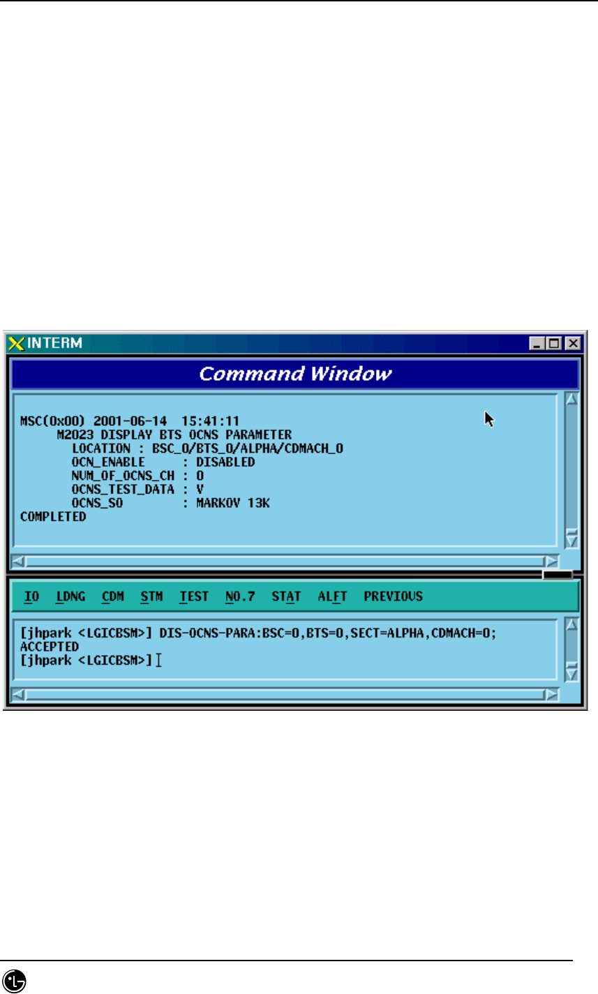
STAREX-IS BSM Manual
Page:179(877)
Issue:1.
0
SMD-011-PMA210
4.3.1.12. OCNS Display
Input the following commands to display transmit gain values, the parameter
information used by the BTS:
• Command DIS-OCNS-PARA:BSC=a,BTS=b,SECT=c,,CDMACH=d;
a : BSC Number (0 ~ 11)
b : BTS Number (0 ~ 47)
c : Sector Number (ALPHA/BETA/GAMMA/DELTA/EPSILON/ZETA)
d : CDMA Channel Number (0 ~ 11)
• Input DIS-OCNS-PARA:BSC=0,BTS=0,SECT=ALPHA,CDMACH=0;
• Output
Fig. 4.3-12 OCNS Display
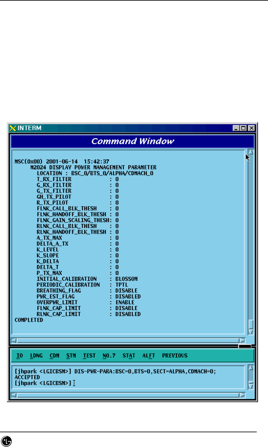
STAREX-IS BSM Manual
Page:180(877)
Issue:1.
0
SMD-011-PMA210
4.3.1.13. Power Management Parameter Information Display
• Command DIS-PWR-PARA:BSC=a,BTS=b,SECT=c,,CDMACH=d;
a : BSC Number (0 ~ 11)
b : BTS Number (0 ~ 47)
c : Sector Number (ALPHA/BETA/GAMMA/DELTA/EPSILON/ZETA)
d : CDMA Channel Number (0 ~ 11)
• Input DIS-PWR-PARA:BSC=0,BTS=0,SECT=ALPHA,CDMACH=0;
• Output
Fig. 4.3-13 Power Management Parameter Information Display
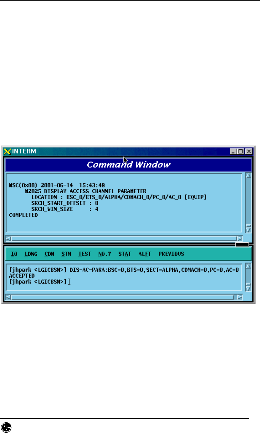
STAREX-IS BSM Manual
Page:181(877)
Issue:1.
0
SMD-011-PMA210
4.3.1.14. Access Channel Parameter Information Display
Display the access channel parameter information.
• Command DIS-AC-PARA:BSC=a,BTS=b,SECT=c,,CDMACH=d,PC=e,AC=f;;
a : BSC Number (0 ~ 11)
b : BTS Number (0 ~ 47)
c : Sector Number (ALPHA/BETA/GAMMA/DELTA/EPSILON/ZETA)
d : CDMA Channel Number (0 ~ 11)
e : Paging Channel ID (0 ~ 6)
f : Access Channel ID (0 ~ 6)
• Input DIS-OCNS-PARA:BSC=0,BTS=0,SECT=ALPHA,CDMACH=0,PC=0,AC=0;
• Output
Fig. 4.3-14 Access Channel Parameter Information Display
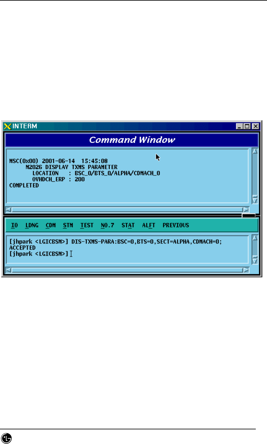
STAREX-IS BSM Manual
Page:182(877)
Issue:1.
0
SMD-011-PMA210
4.3.1.15. TXMS Display
• Command DIS-TXMS-PARA:BSC=a,BTS=b,SECT=c,,CDMACH=d;
a : BSC Number (0 ~ 11)
b : BTS Number (0 ~ 47)
c : Sector Number (ALPHA/BETA/GAMMA/DELTA/EPSILON/ZETA)
d : CDMA Channel Number (0 ~ 11)
• Input DIS-TXMS-PARA:BSC=0,BTS=0,SECT=ALPHA,CDMACH=0;
• Output
Fig. 4.3-15 TXMS Display
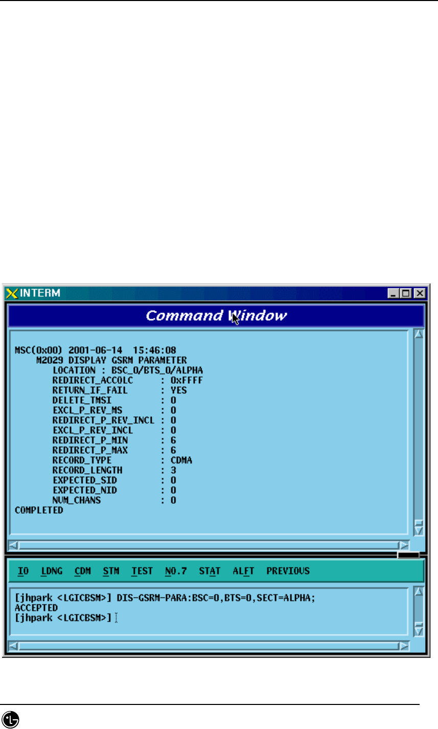
STAREX-IS BSM Manual
Page:183(877)
Issue:1.
0
SMD-011-PMA210
4.3.1.16. GSRM Parameter Information Display
GSRM(Global Service Redirect Message) is the parameter information that determines
the system where a call is to be tried after MS power is on. It can be inquired using
the following commands:
• Command DIS-GSRM-PARA:BSC=a,BTS=b,SECT=c;
a : BSC Number (0 ~ 11)
b : BTS Number (0 ~ 47)
c : Sector Number (ALPHA/BETA/GAMMA/DELTA/EPSILON/ZETA)
• Input DIS-GSRM-PARA:BSC=0,BTS=0,SECT=ALPHA;
• Output

STAREX-IS BSM Manual
Page:184(877)
Issue:1.
0
SMD-011-PMA210
Fig. 4.3-16 GSRM Parameter Information Display

STAREX-IS BSM Manual
Page:185(877)
Issue:1.
0
SMD-011-PMA210
4.3.1.17. Access Parameter Message Display
As an Overhead message that is transmitted from BTS to MS through the paging
channel, the Access Parameter Message indicates the way for MS to access BTS
through Access channel contains the information to be used for the call processing,
handoff procedures, registration, etc. Input the following command to display the
Access Parameter Message.
• Command DIS-ACC-PARA:BSC=a,BTS=b,SECT=c,CDMACH=d, PC=e;
a : BSC Number (0 ~ 11)
b : BTS Number (0 ~ 47)
c : Sector Number (ALPHA/BETA/GAMMA/DELTA/EPSILON/ZETA)
d : CDMA Channel Number (0 ~ 11)
e : Paging Channel ID
• Input DIS-ACC-PARA:BSC=0,BTS=0,SECT=ALPHA,CDMACH=0,PC=0;
• Output
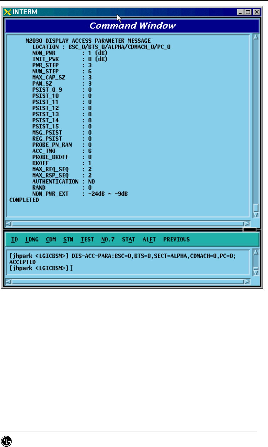
STAREX-IS BSM Manual
Page:186(877)
Issue:1.
0
SMD-011-PMA210
Fig. 4.3-17 Access Parameter Message Display
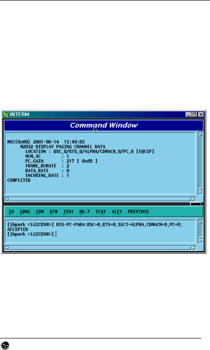
STAREX-IS BSM Manual
Page:187(877)
Issue:1.
0
SMD-011-PMA210
4.3.1.18. Paging Channel Parameter Information Display
Use the following command to display the transmit value of the paging channel:
• Command DIS-PC-PARA:BSC=a,BTS=b,SECT=c,CDMACH=d, PC=e;
a : BSC Number (0 ~ 11)
b : BTS Number (0 ~ 47)
c : Sector Number (ALPHA/BETA/GAMMA/DELTA/EPSILON/ZETA)
d : CDMA Channel Number (0 ~ 11)
e : Paging Channel ID
• Input DIS-PC-PARA:BSC=0,BTS=0,SECT=ALPHA,CDMACH=0,PC=0;
• Output
Fig. 4.3-18 Paging Channel Parameter Information Display
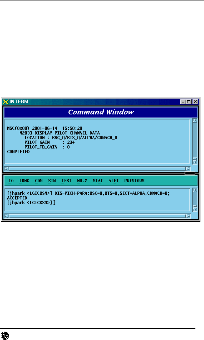
STAREX-IS BSM Manual
Page:188(877)
Issue:1.
0
SMD-011-PMA210
4.3.1.19. Pilot Channel Parameter Information Display
Use the following command to display the gain value of the pilot channel:
• Command DIS-PICH-PARA:BSC=a,BTS=b,SECT=c,CDMACH=d;
a : BSC Number (0 ~ 11)
b : BTS Number (0 ~ 47)
c : Sector Number (ALPHA/BETA/GAMMA/DELTA/EPSILON/ZETA)
d : CDMA Channel Number (0 ~ 11)
• Input DIS-PICH-PARA:BSC=0,BTS=0,SECT=ALPHA,CDMACH=0;
• Output
Fig. 4.3-19 Pilot Channel Parameter Information Display
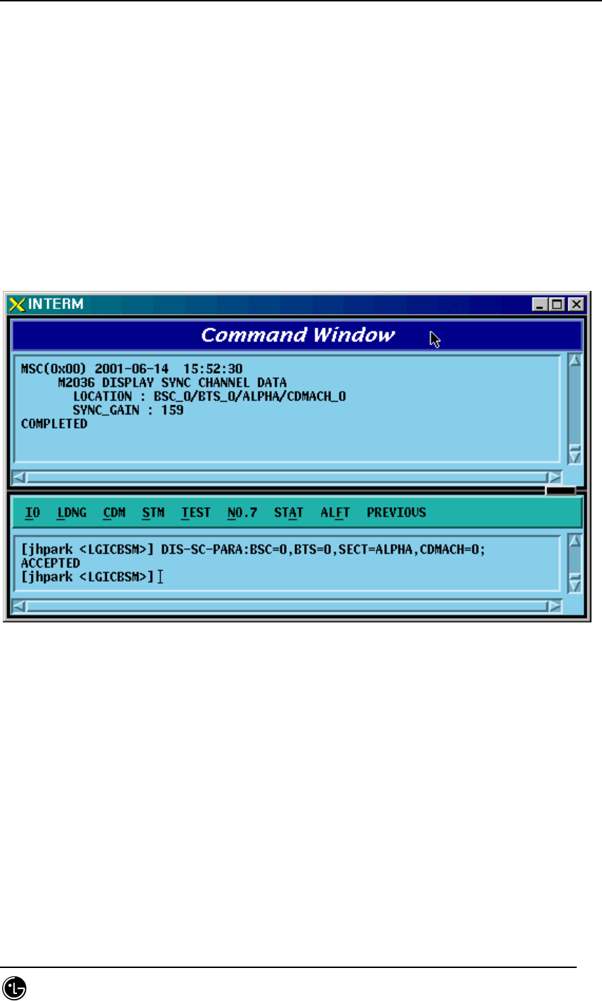
STAREX-IS BSM Manual
Page:189(877)
Issue:1.
0
SMD-011-PMA210
4.3.1.20. Sync. Channel Parameter Information Display
Use the following command to display the gain value of the sync. channel:
• Command DIS-SC-PARA:BSC=a,BTS=b,SECT=c,CDMACH=d;
a : BSC Number (0 ~ 11)
b : BTS Number (0 ~ 47)
c : Sector Number (ALPHA/BETA/GAMMA/DELTA/EPSILON/ZETA)
d : CDMA Channel Number (0 ~ 11)
• Input DIS-SC-PARA:BSC=0,BTS=0,SECT=ALPHA,CDMACH=0;
• Output
Fig. 4.3-20 Sync. Channel Parameter Information Display
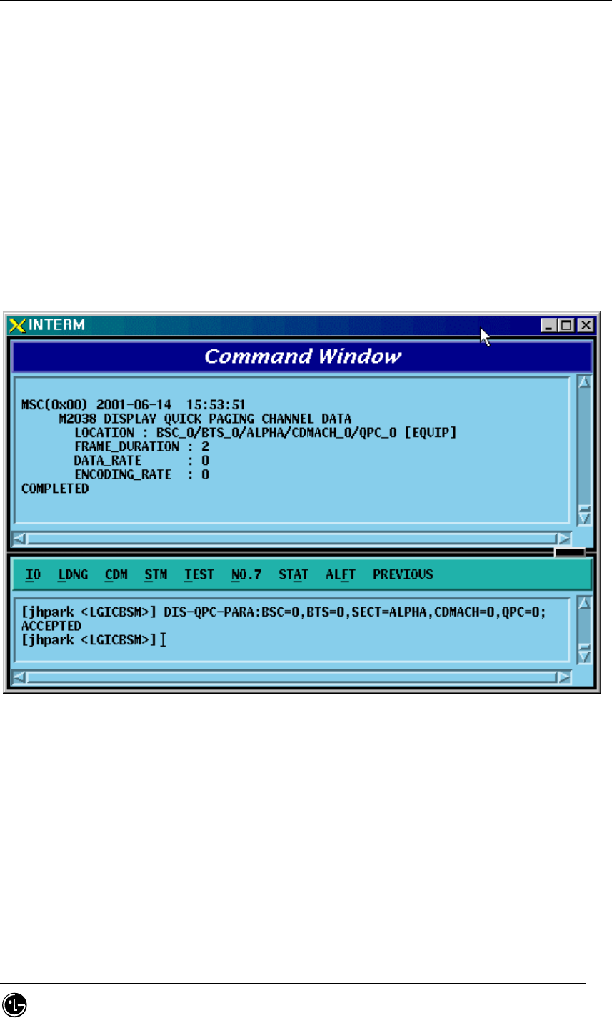
STAREX-IS BSM Manual
Page:190(877)
Issue:1.
0
SMD-011-PMA210
4.3.1.21. Quick Paging Channel Parameter Information Display
Use the following command to display the gain value of the quick paging channel:
• Command DIS-QPC-PARA:BSC=a,BTS=b,SECT=c,CDMACH=d, QPC=e;
a : BSC Number (0 ~ 11)
b : BTS Number (0 ~ 47)
c : Sector Number (ALPHA/BETA/GAMMA/DELTA/EPSILON/ZETA)
d : CDMA Channel Number (0 ~ 11)
e : Quick Paging Channel ID
• Input DIS-QPC-PARA:BSC=0,BTS=0,SECT=ALPHA,CDMACH=0, QPC=0;
• Output
Fig. 4.3-21 Quick Paging Channel Parameter Information Display
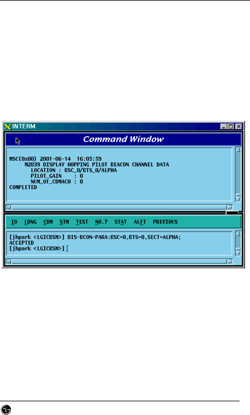
STAREX-IS BSM Manual
Page:191(877)
Issue:1.
0
SMD-011-PMA210
4.3.1.22. Hopping Pilot Beacon Channel Parameter Information Display
• Command DIS-BCON-PARA:BSC=a,BTS=b,SECT=c;
a : BSC Number (0 ~ 11)
b : BTS Number (0 ~ 47)
c : Sector Number (ALPHA/BETA/GAMMA/DELTA/EPSILON/ZETA)
• Input DIS-BCON-PARA:BSC=0,BTS=0,SECT=ALPHA;
• Output
Fig. 4.3-22 Hopping Pilot Beacon Channel Parameter Information Display
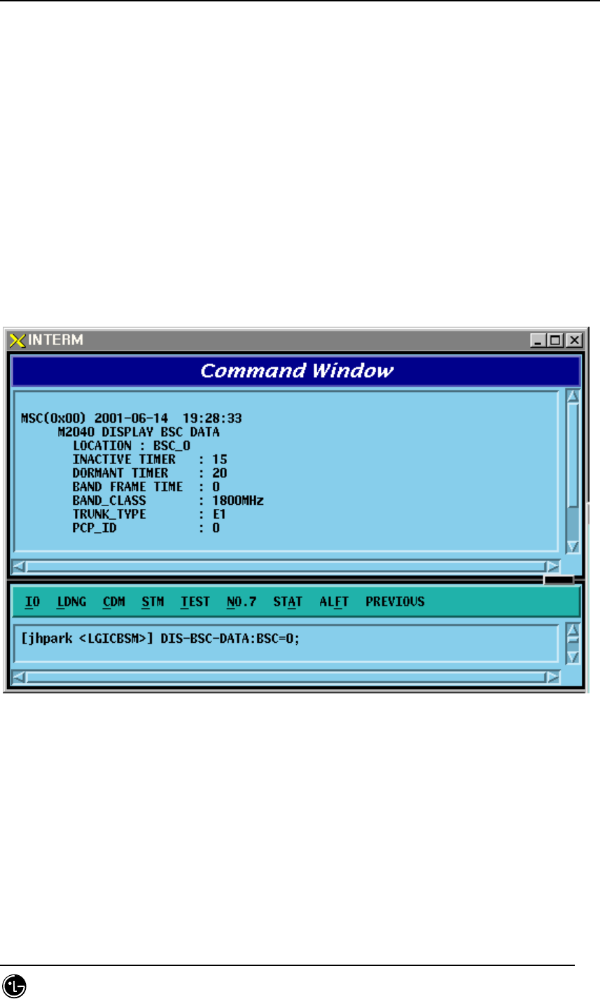
STAREX-IS BSM Manual
Page:192(877)
Issue:1.
0
SMD-011-PMA210
4.3.2. Parameter Information Display
(Display_Parameter_Information_2)
4.3.2.1. BSC Information Verification
• Command DIS-BSC-DATA: BSC=a;
a : BSC Number(0~11)
• Input DIS-BSC-DATA: BSC=0;
• Output
Fig. 4.3-23 BSC Information Verification
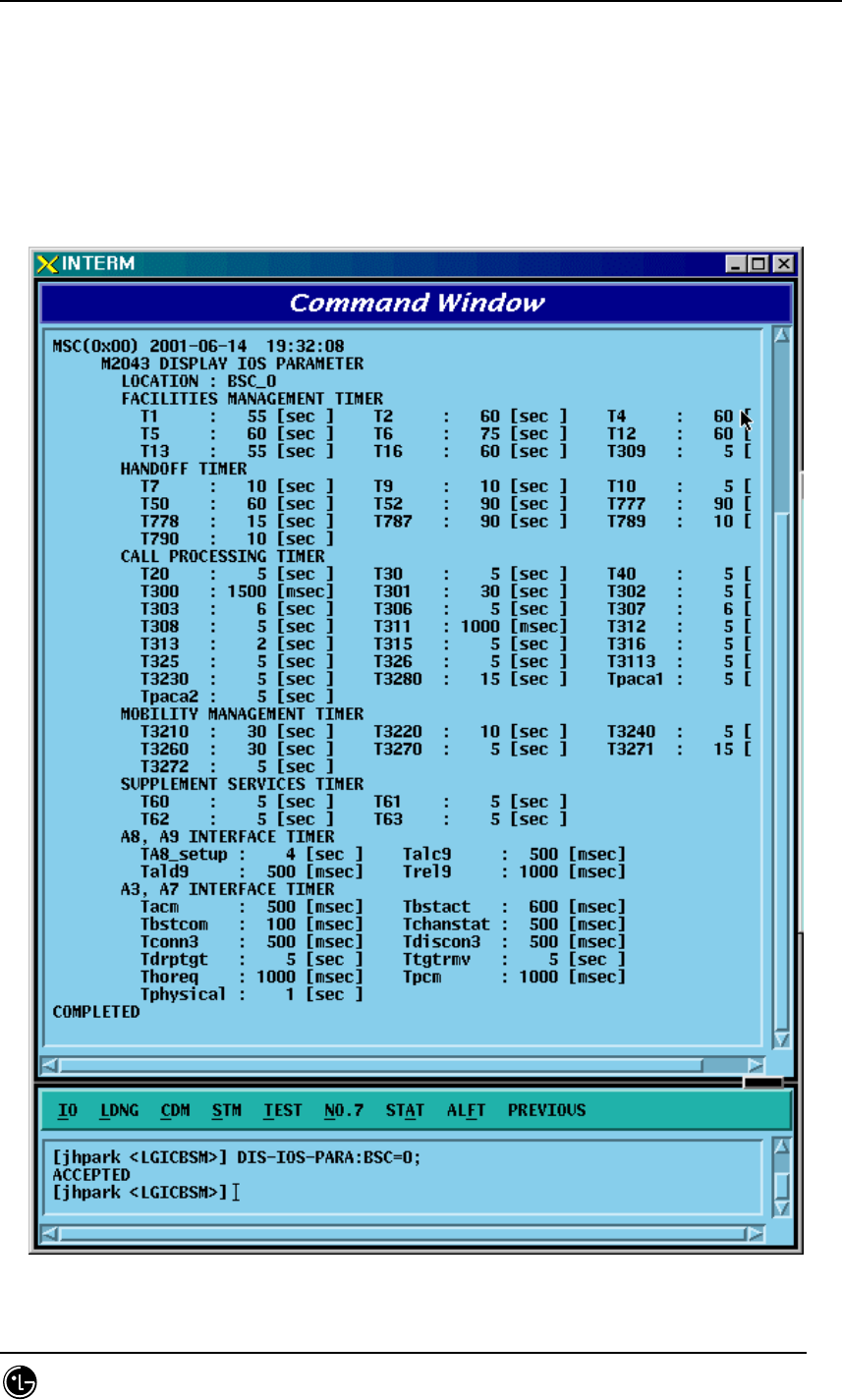
STAREX-IS BSM Manual
Page:193(877)
Issue:1.
0
SMD-011-PMA210
4.3.2.2. IOS Parameter Verification
• Command DIS-IOS-PARA: BSC=a;
a : BSC Number(0~11)
• Input DIS-IOS-PARA: BSC=0;
• Output
Fig. 4.3-24 IOS Parameter Verification
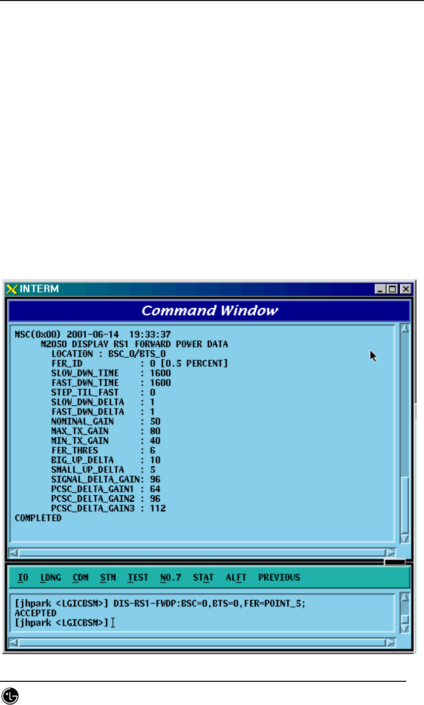
STAREX-IS BSM Manual
Page:194(877)
Issue:1.
0
SMD-011-PMA210
4.3.2.3. Forward Link Power Management Information (RS1) Verification
Rate Set 1 transmits data at the speed of 9600,4800,2400,1200 bps. Input the following
command to check the parameter information for RS1 Forward Link Power
Management. Among the input values, FER (Frame Error Rate) has the value ranging
from 0.5%, 1 to 5%.
• Command DIS-RS1-FWDP: BSC=a, BTS=b, FER=c;
a : BSC Number(0~11)
b: BTS Number(0~47)
c:FER
(POINT_5/PERCENT_1/PERCENT_2/PERCENT_3/PERCENT_4/PERCET_5)
• Input DIS-RS1-FWDP: BSC=0, BTS=0, FER=POINT_5;
• Output

STAREX-IS BSM Manual
Page:195(877)
Issue:1.
0
SMD-011-PMA210
Fig. 4.3-25 Forward Link Power Management Information (RS1) Verification
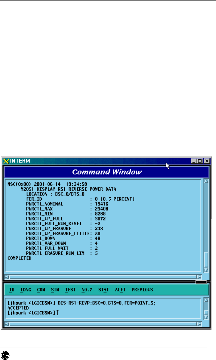
STAREX-IS BSM Manual
Page:196(877)
Issue:1.
0
SMD-011-PMA210
4.3.2.4. Backward Link Power Management Information (RS1)
Verification
Rate Set 1 transmits data at the speed of 9600,4800,2400,1200 bps. Input the following
command to check the parameter information for RS1 backward Link Power
Management. Among the input values, FER (Frame Error Rate) has the value ranging
from 0.5%, 1 to 5%.
• Command DIS-RS1-REVP: BSC=a, BTS=b, FER=c;
a : BSC Number(0~11)
b: BTS Number(0~47)
c:FER
(POINT_5/PERCENT_1/PERCENT_2/PERCENT_3/PERCENT_4/PERCET_5)
• Input DIS-RS1-REVP: BSC=0, BTS=0, FER=POINT_5;
• Output

STAREX-IS BSM Manual
Page:197(877)
Issue:1.
0
SMD-011-PMA210
Fig. 4.3-26 Backward Link Power Management Information (RS1) Verification

STAREX-IS BSM Manual
Page:198(877)
Issue:1.
0
SMD-011-PMA210
4.3.2.5. Forward Link Power Management (RS2) Verification
Rate Set 2 transmits data at the speed of 14400,7200,3600,1800 bps. Input the
following command to check the parameter information for RS2 Forward Link Power
Management. Among the input values, FER (Frame Error Rate) has the value ranging
from 0.5%, 1 to 5%.
• Command DIS-RS2-FWDP: BSC=a, BTS=b, FER=c;
a : BSC Number(0~11)
b: BTS Number(0~47)
c:FER
(POINT_5/PERCENT_1/PERCENT_2/PERCENT_3/PERCENT_4/PERCET_5)
• Input DIS-RS2-FWDP: BSC=0, BTS=0, FER=POINT_5;
• Output
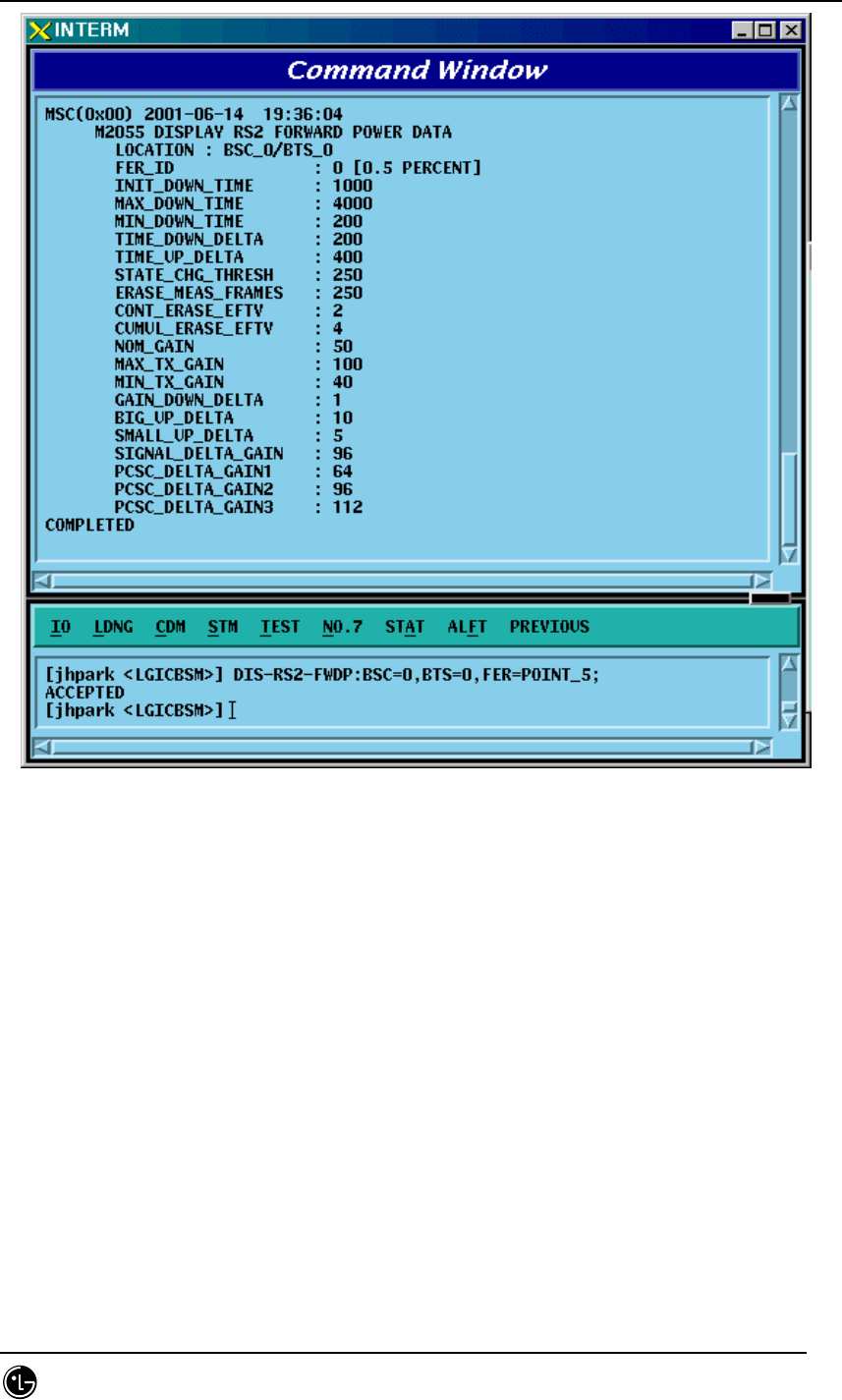
STAREX-IS BSM Manual
Page:199(877)
Issue:1.
0
SMD-011-PMA210
Fig. 4.3-27 Forward Link Power Management Information (RS2) Verification