LG Electronics USA 3G1XINBTS STAREX-IS 1900 Indoor BTS User Manual STAREX IS User s Manual
LG Electronics USA STAREX-IS 1900 Indoor BTS STAREX IS User s Manual
Contents
Users Manual Part D
STAREX-IS BSM Manual
Page:449(877)
Issue:1.
0
SMD-011-PMA210
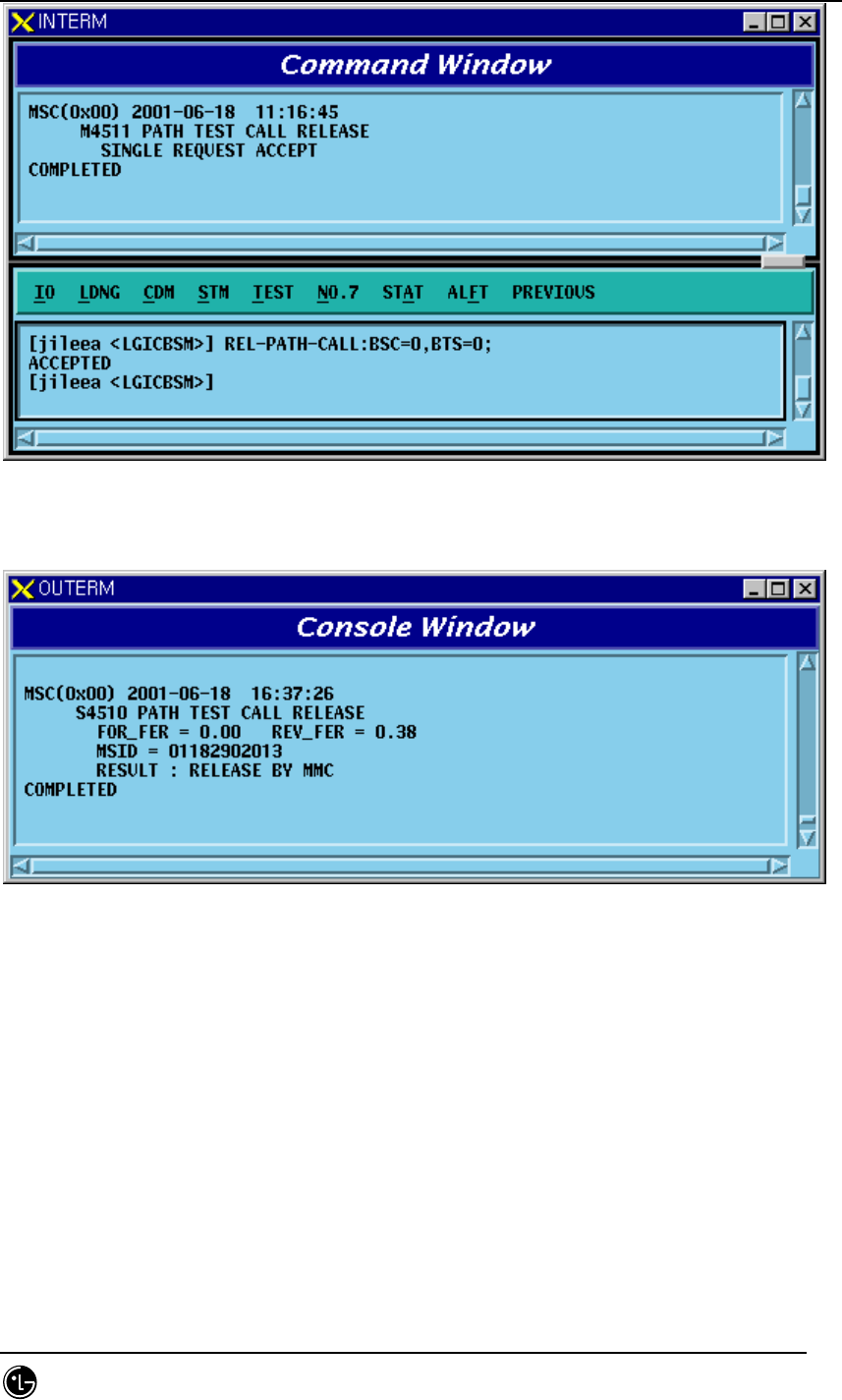
Fig. 4.5-27 Traffic Path Release Command Execution Result Display(Interm Window)
Fig. 4.5-28 Traffic Path Release Command Execution Result Display(Console Window)

STAREX-IS BSM Manual
Page:450(877)
Issue:1.
0
SMD-011-PMA210
4.5.7. Call Trace Testing Function
Mobile Call Trace Function traces the process of call setup for the MS, surveillance of
the status after the call setup, the process of call release, and displays the content
visibly to BSM after BSM of User’s terminal designates a Mobile Station(MS) at
random by using a value of MSIN(Mobile Station Identification Number). . The
designated Mobile Station(MS) can trace the originating call or terminating call that
was set up by the user and if necessary, it sets up Markov call(i.e., a terminating
Markov call by paging) for tracing. Mobile call tracing can be performed to all kinds of
calls(Voice Call, Data Call, HandOff Call) and can designate maximum two calls
simultaneously for tracing. Information provided upon call tracing is as follows:
Tracing Information when Call is set
Resource of Call to be set
System Resource: BSC No, BTS No, Sector No, PN Offset
Attributes of Call: IMSI, ESN, Service Option, Call Type(Voice Call originating, Voice
Call terminating, DATA Call initial set, DATA Call Reactivation by MS, DATA Call
Reactivation by Network), Terminating number
BTS Resource: CDMA CH(Frequency) No, TC No(RCP#, MCPA#, CE#),
Code CH(Walsh code), Frame Offset
BSC Resource: SLP, VCE Number, CIC(Circuit Identifier Code)
Setup Process
Message display between processors during Call Setup: Visible Display of Call Flow
During Call Setup, display RTD(Round Trip Delay) value and calculated distance by
using this.
When Call Failure occurs, display reason value and its meaning
Call Set Time by section
Tracing Information at the phase of calling after Call Setup: Tracing and Display at
intervals of 1 ~ 5 seconds.
Elements of Communication Quality
Forward FER(Frame Error Rate): Present FER, Total FER
Backward FER(Frame Error Rate): Present FER, Total FER
Power Control Parameter: TC Gain, Reverse Power Control Threshold
Location Estimate Elements
Present Active PN Offsets Aggregation : BSC No, BTS No, Sector, Cdma Ch,
Walsh_ch, TC Id, RTD
STAREX-IS BSM Manual
Page:451(877)
Issue:1.
0
SMD-011-PMA210
Present RTD Value and calculated distance by using this
Tracing Information at the phase of Call Release: Tracing it every time at the normal
release or abnormal release
Reason for Call Release
Reason for Call Release and its content: Display reason value and its meaning
Quality Elements of Call
Forward Total FER(Frame Error Rate)
Backward Total FER(Frame Error Rate)
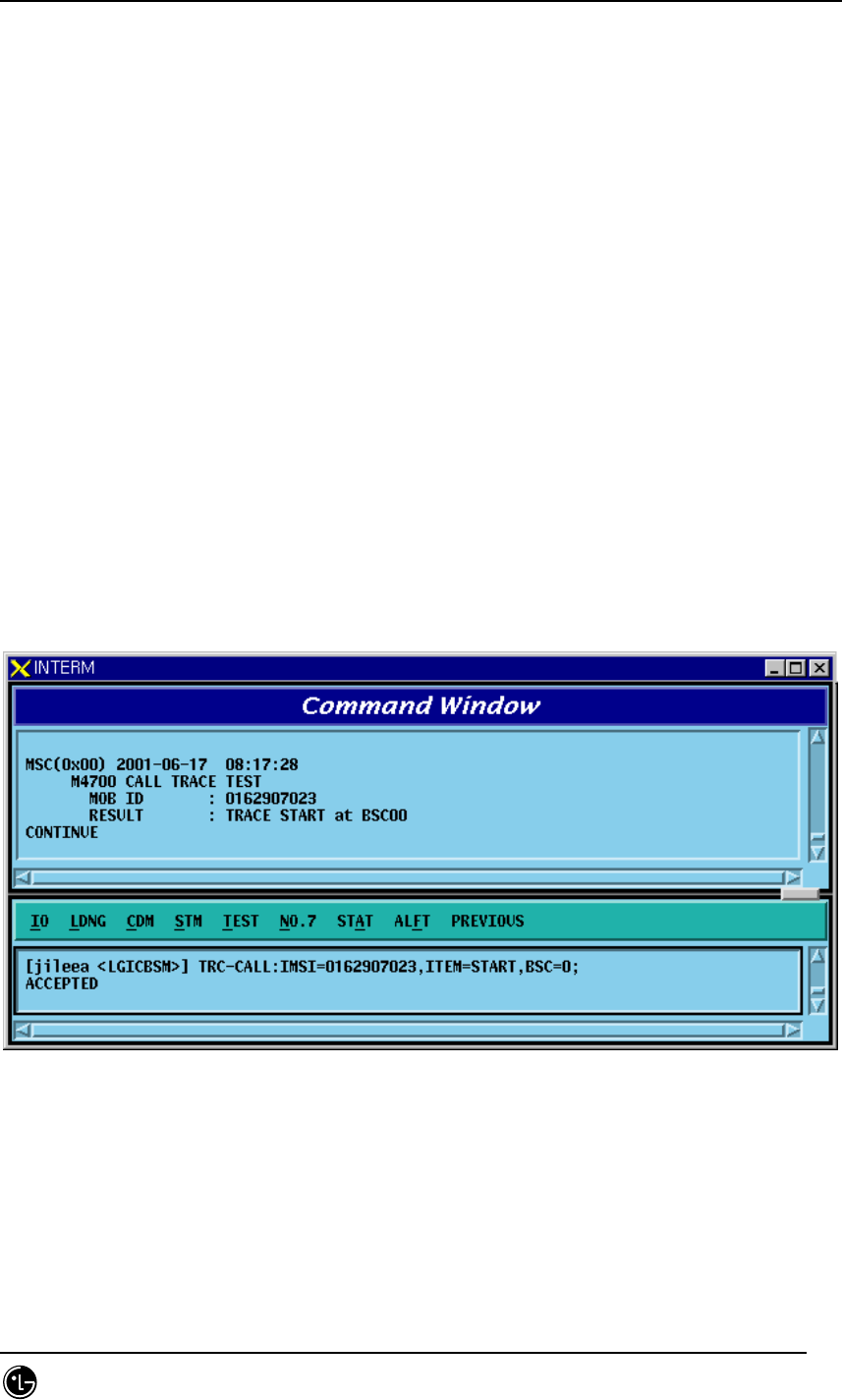
4.5.7.1. Call Trace Start/End Function
Function that starts/ends Call Trace with MS designated at random.
• Command TRC-CALL : IMSI=a, ITEM=b,BSC=c;
a: IMSI Number
b: Start / Stop
c: BSC ID
• Input/Output
Fig. 4.5-29 Call Trace Start Command Input Screen
STAREX-IS BSM Manual
Page:452(877)
Issue:1.
0
SMD-011-PMA210
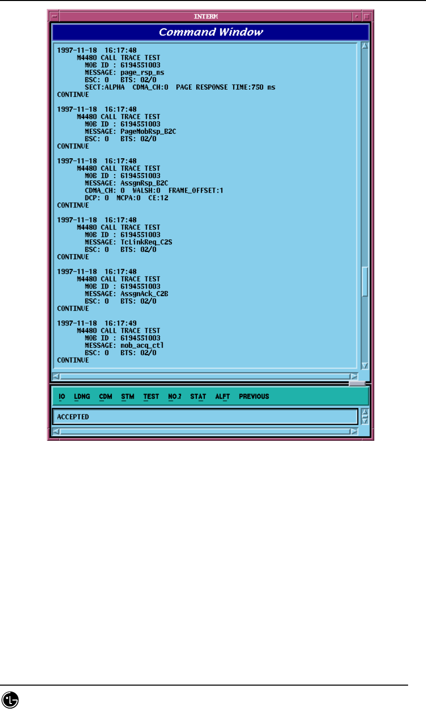
Fig. 4.5-30 Call Trace Display in the Process of Call Set
STAREX-IS BSM Manual
Page:453(877)
Issue:1.
0
SMD-011-PMA210
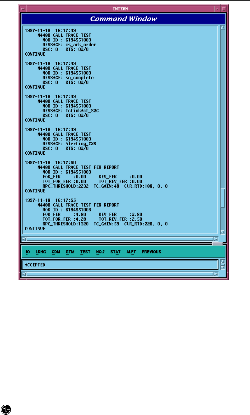
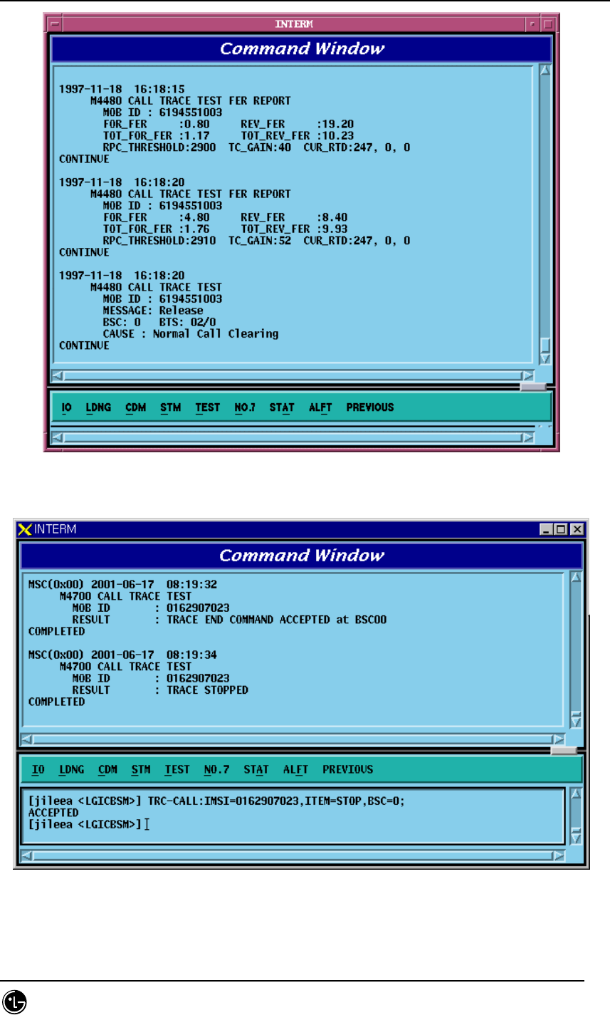
Fig. 4.5-31 Display of Call Set Process and Elements of Communication Quality
STAREX-IS BSM Manual
Page:454(877)
Issue:1.
0
SMD-011-PMA210
Fig. 4.5-32 Display of Communication Quality and Release Reason
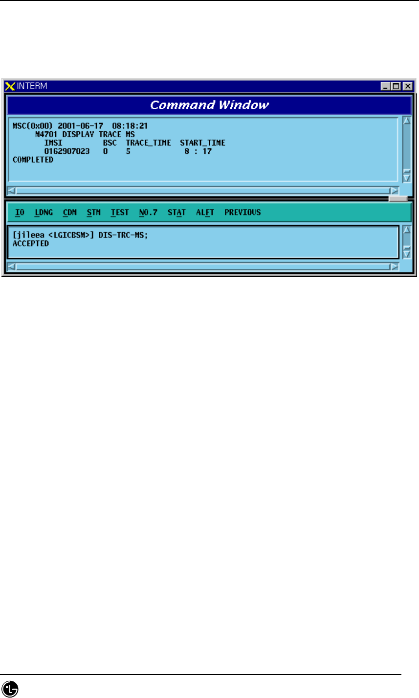
Fig. 4.5-33 Call Trace Stop Result
STAREX-IS BSM Manual
Page:455(877)
Issue:1.
0
SMD-011-PMA210
4.5.7.2. Call Trace MS Display Function
Function to display MS that currently uses the mobile call tracing function.
• Command DIS-TRC-MS;
• Input/Output
Fig. 4.5-34 Terminal Display in use of Call Trace
STAREX-IS BSM Manual
Page:456(877)
Issue:1.
0
SMD-011-PMA210
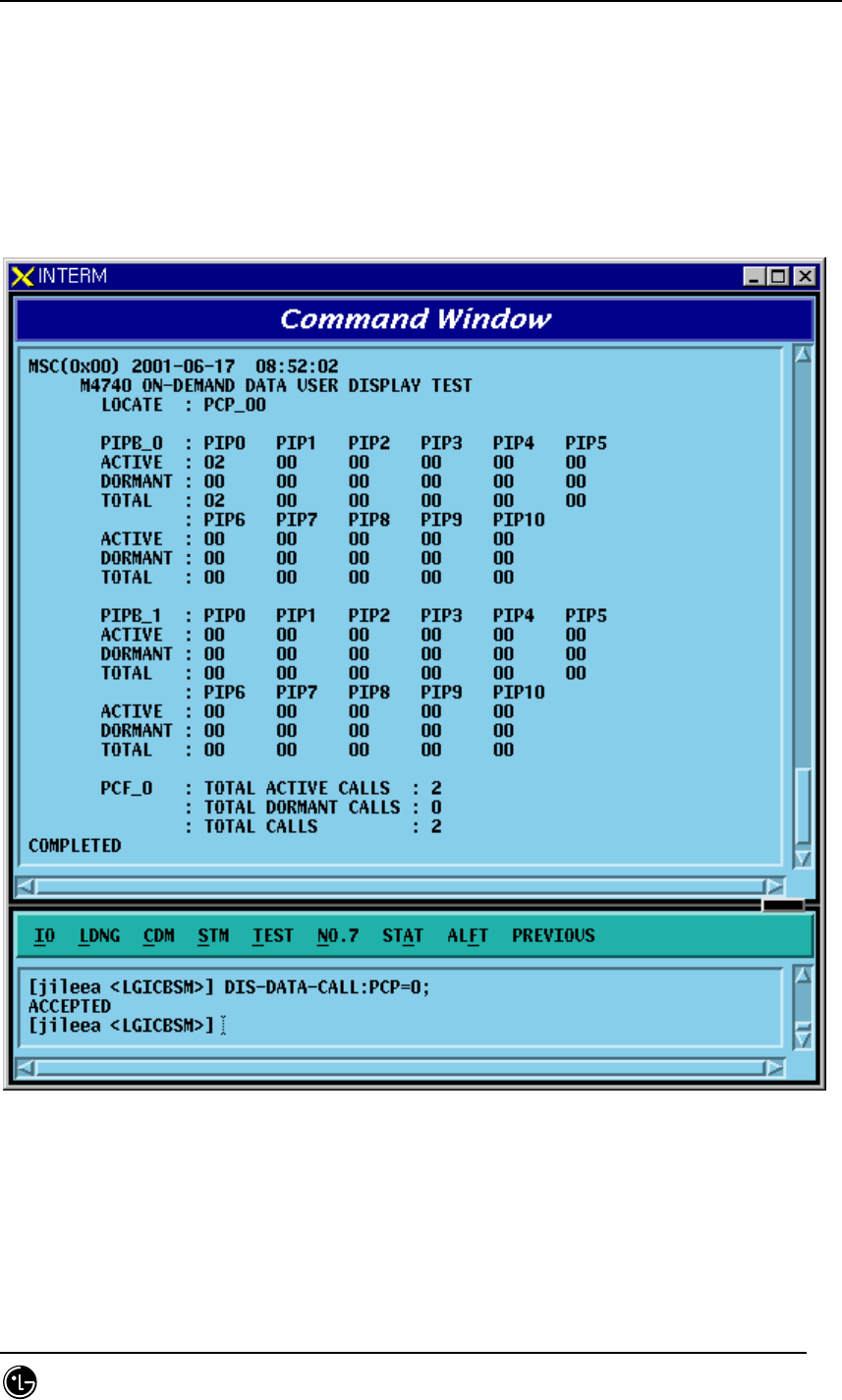
4.5.8. Number of Data Call User Display Function
(Active/Dormant)
Function to display Number of Data Call by Active/Dormant
• Command DIS-DATA-CALL:PCP=a;
a: PCP Number(0~2)
• Input/Output
Fig. 4.5-35 Result of the Number of DATA Call User Display
STAREX-IS BSM Manual
Page:457(877)
Issue:1.
0
SMD-011-PMA210
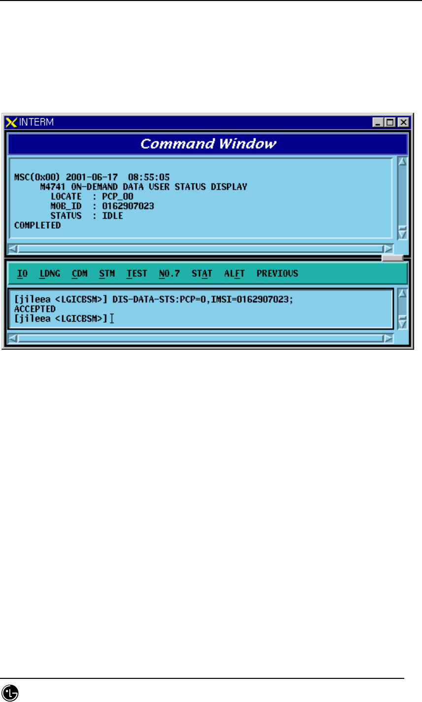
4.5.9. DATA Call User Status Display Function by IMSI
Command DIS-DATA-STS:PCP=a,IMSI=b;
a: PCP Number(0~2)
b: IMSI of MS
• Input/Output
Fig. 4.5-36 Result of DATA Call User Status Display by IMSI
STAREX-IS BSM Manual
Page:458(877)
Issue:1.
0
SMD-011-PMA210
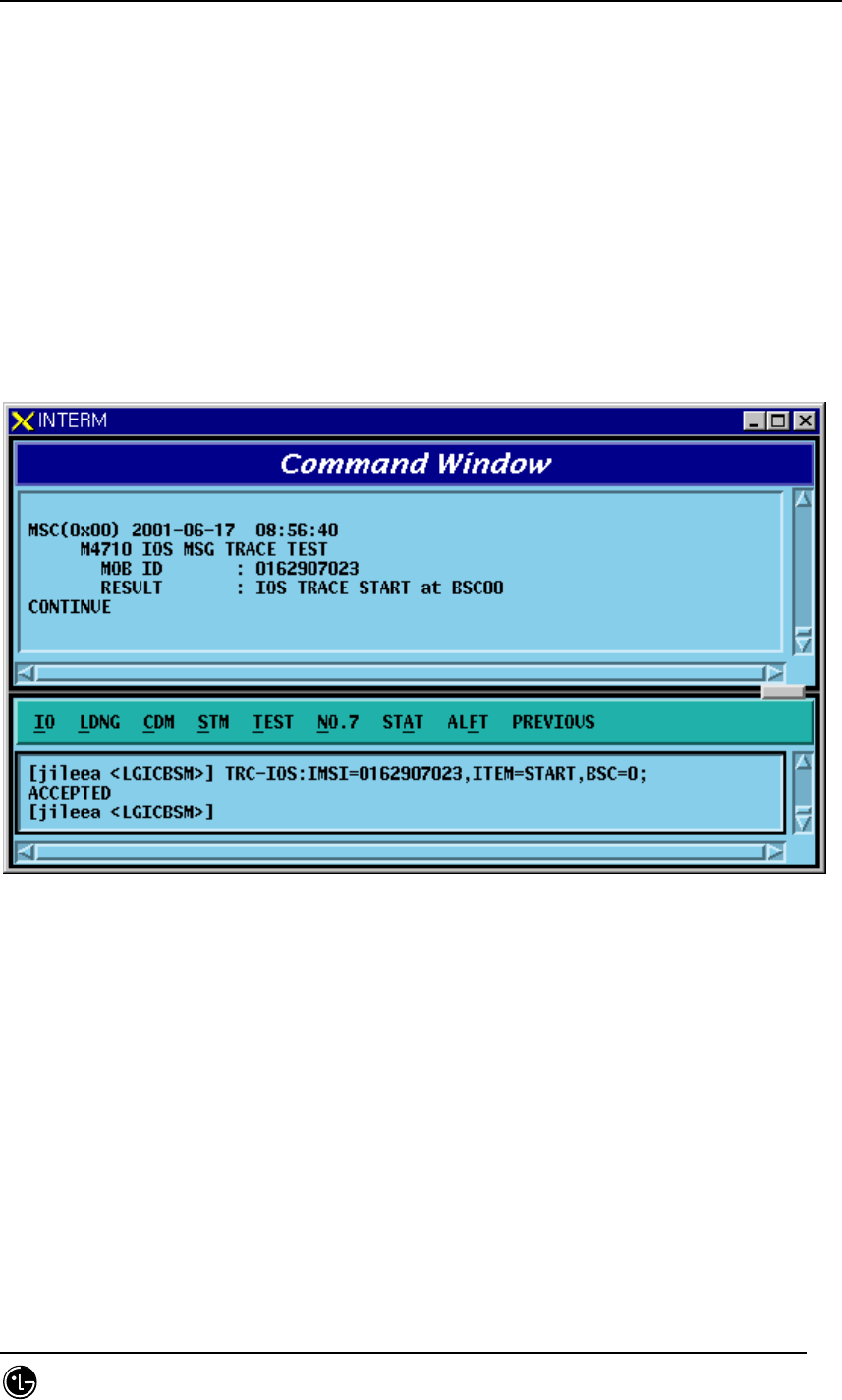
4.5.10. IOS Message Display Function
This function is operated by inputting the IMSI of MS to trace, duration, etc in BSM and
displays IOS trace information for all kinds of calls that MS attempts as visible
information in text format in the BSM.
• Command TRC-IOS : MS=a, BSC=b, FLAG=c, DURATION=d
a: MS Number
b: BSC ID(0~11)
c: Start/Stop
d: Trace Duration Time
• Input/Output
Fig. 4.5-37 IOS Message Display START Result
STAREX-IS BSM Manual
Page:459(877)
Issue:1.
0
SMD-011-PMA210
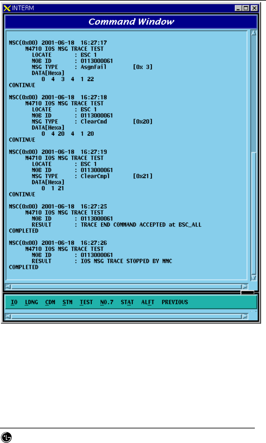
Fig. 4.5-38 IOS Display Message
STAREX-IS BSM Manual
Page:460(877)
Issue:1.
0
SMD-011-PMA210
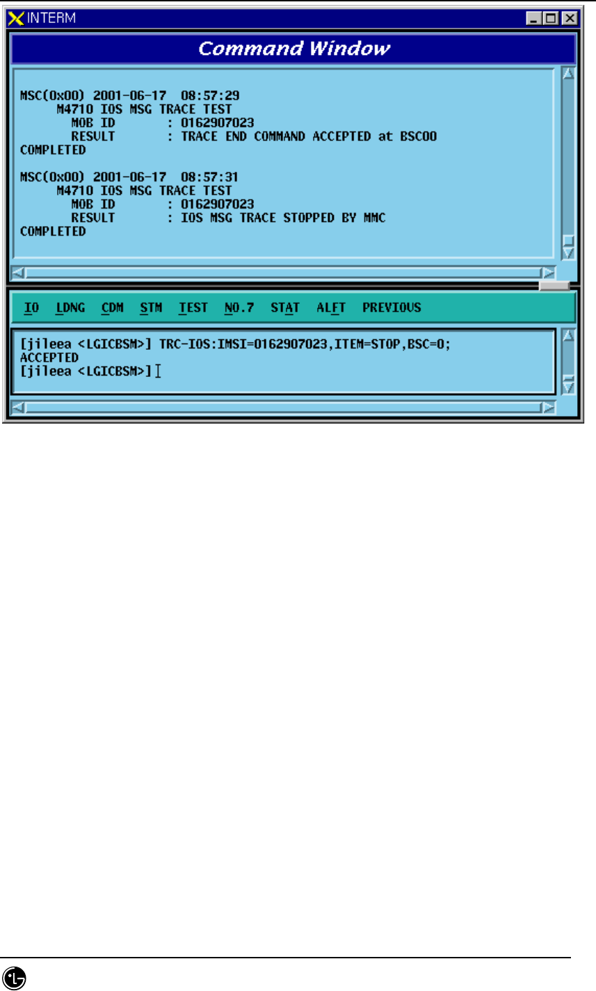
Fig. 4.5-39 STOP Result of IOS Message Display Function
STAREX-IS BSM Manual
Page:461(877)
Issue:1.
0
SMD-011-PMA210
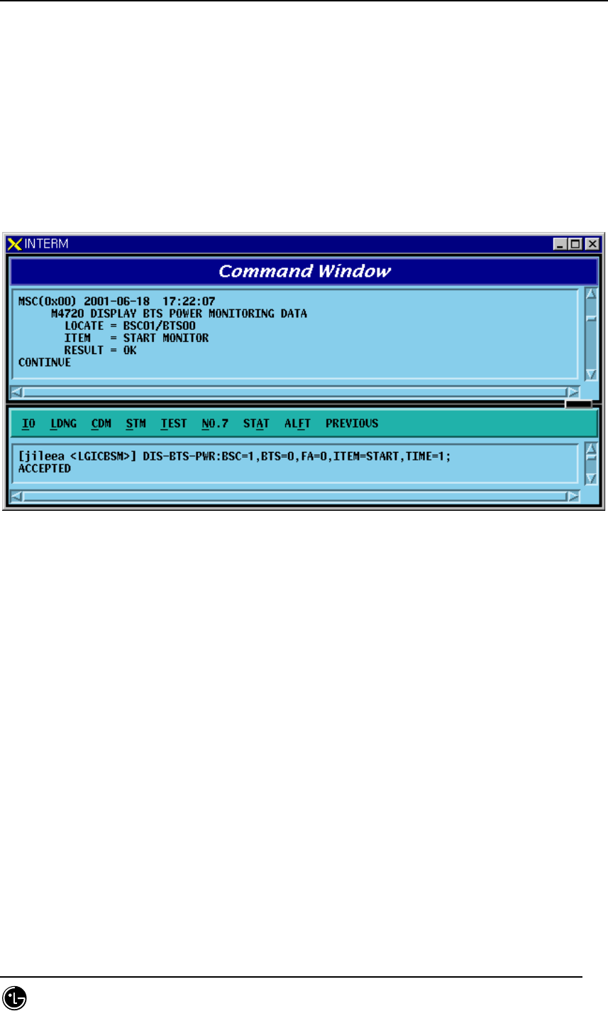
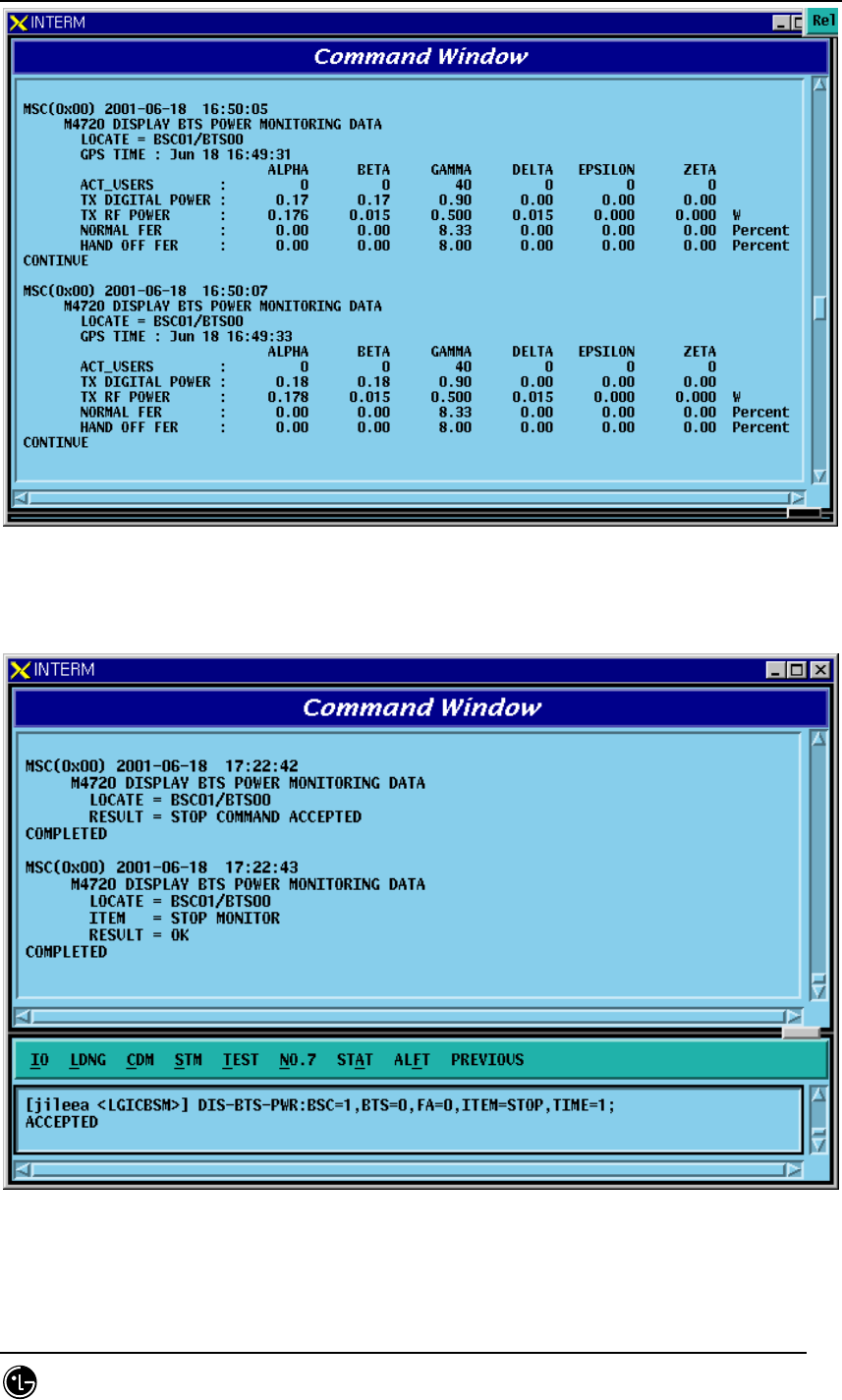
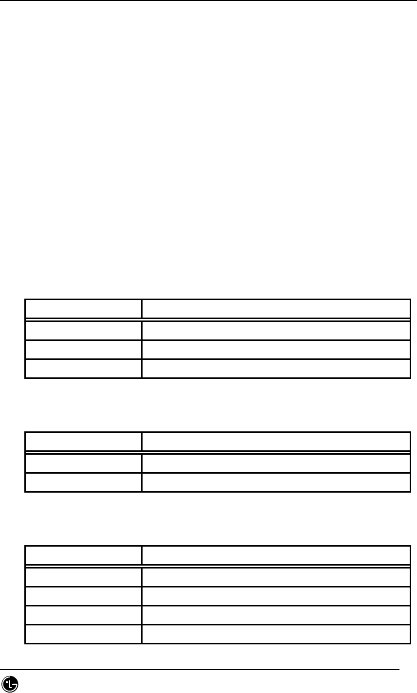
4.5.11. POWER MONITORING Function
Function to check the BTS power control in BSM
• Command DIS-BTS-PWR:BSC=a,BTS=b,ITEM=c,[TIME=d]:
a: BSC ID(0~11)
b: BTS ID(0~47)
c: Stop/Start
d: Duration Time(1~100 min)
• Input/Ouput
Fig. 4.5-40 Power Monitoring START Result
STAREX-IS BSM Manual
Page:462(877)
Issue:1.
0
SMD-011-PMA210
Fig. 4.5-41 Power Monitoring Result
Fig. 4.5-42 Power Monitoring STOP Result
STAREX-IS BSM Manual
Page:463(877)
Issue:1.
0
SMD-011-PMA210
4.6. No.7 Command
The function of BSM No.7 is to manage parameter information necessary for the
operator to operate No.7. It is divided into the following function: 1) signaling link
operation management and 2) the signaling link maintenance. The former is composed
of the following: signaling point management function, signaling link set management
function, signaling link management function, signaling terminal management function,
signaling data management function, and SCCP management function. The latter is
composed of signaling link and signaling terminal test, and signal link inhibit.
4.6.1. Related Command
4.6.1.1. Commands for Signaling Link Operation and Management
Function
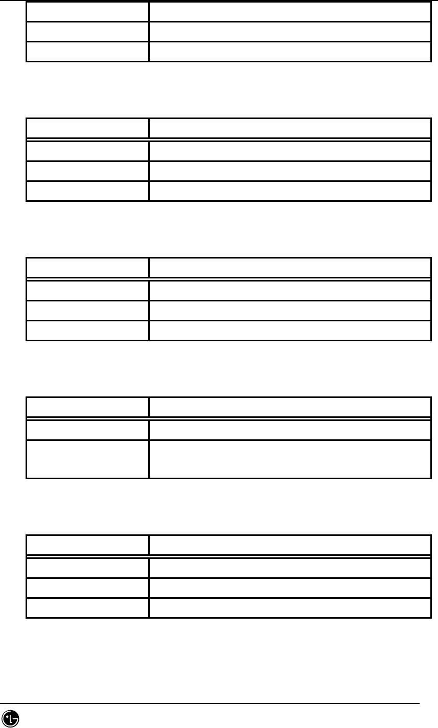
Table 4.6-1 Commands related to Signaling Point Management
Commands Description
DIS-SP-INFO Signaling Point Information Display
CHG-OSP Change of Intra-Switching Office Signaling Point
CHG-SP Change of Signaling Point
Table 4.6-2 Commands related to Signaling Link Set
Commands Description
ACT-LKS Signaling Link Set Activation
DACT-LKS Signaling Link Set Deactivation
Table 4.6-3 Commands related to Signaling Link
Commands Description
CRET-SLK Signaling Link Create
DEL-SLK Signaling Link Deletion
ACT-SLK Signaling Link Activation
DACT-SLK Signaling Link Deactivation
STAREX-IS BSM Manual
Page:464(877)
Issue:1.
0
SMD-011-PMA210
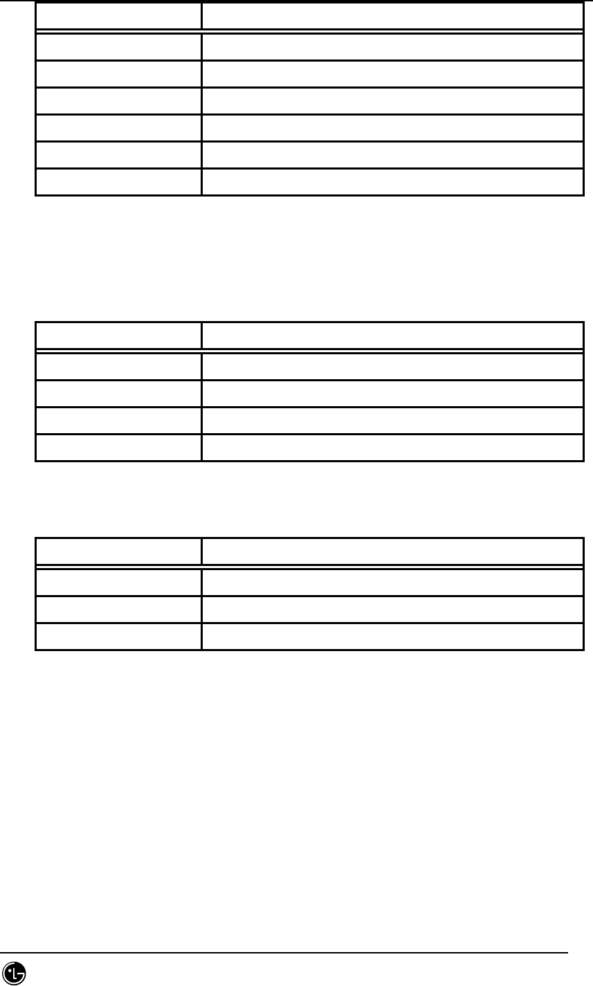
DIS-SLK-INFO Signaling Link Information Display
INH-SLK Signaling Link Barring
ALW-SLK Signaling Link Barring Release
Table 4.6-4 Commands related to Signaling Terminal
Commands Description
CRTE-ST Signaling Terminal Definition(Create)
DEL-ST Signaling Terminal Deletion
DIS-ST-INFO Signaling Terminal Information Display
Table 4.6-5 Commands related to Signaling Data Link
Commands Description
CRTE-SDLK Signaling Data Link Definition(Create)
DEL-SDLK Signaling Data Link Deletion
DIS-SDLK-INFO Signaling Data Link Information Display
Table 4.6-6 Display Commands for SCCP Data
Commands Description
DIS-SCCP-NET SCCP Network Configuration Data Display
DIS-SCCP-LSS SCCP Intra-Switching Office Sub-system Status Data
Display
Table 4.6-7 Signaling Link Status Display Commands
Commands Description
DIS-SLK-STS Signaling Link Status Display
DIS-ST-STS Signaling Terminal Status Display
DIS-LKS-STS Signaling Link Set Status Display
Table 4.6-8 Commands related to Timer
STAREX-IS BSM Manual
Page:465(877)
Issue:1.
0
SMD-011-PMA210
Commands Description
DIS-MTP2-TMR MTP L2 Timer Display
CHG-MTP2-TMR MTP L2 Timer Change
DIS-MTP3-TMR MTP L3 Timer Display
CHG-MTP3-TMR MTP L3 Timer Change
DIS-SCCP-TMR SCCP Timer Change
CHG-SCCP-TMR SCCP Timer Change
4.6.1.2. Commands for Signaling Link Maintenance Function
Table 4.6-9 Test Related Commands
Commands Description
TEST-SLK Signaling Link Test
TEST-ST Signaling Terminal Test
DIS-No7-CYC Test Cycle Display
CHG-No7-CYC Test Cycle Change
Table 4.6-10 Status Suppression Related Commands
Commands Description
DIS-INH-NO7 Displayable Status Message Display
ALW-N07-MSG Status Message Display Possible
INH-NO7-MSG Status Message Display Suppression
4.6.2. Signaling Link Operation Management Function
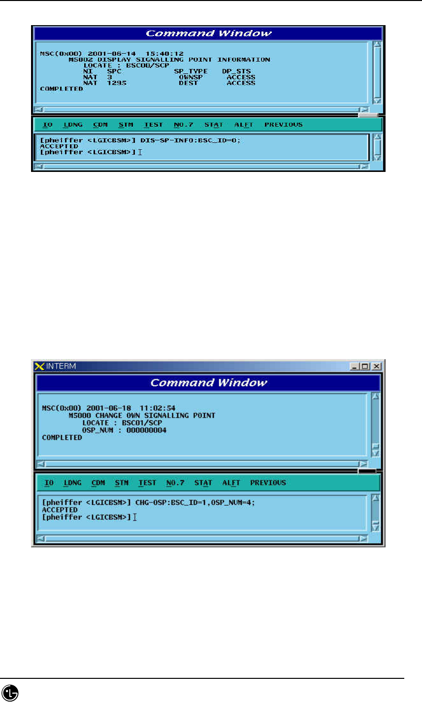
4.6.2.1. Signaling Point Information Display
Display the Status of Signaling Point of local Switching Office and that of Intra-
Switching Office.
Command DIS-SP-INFO:BSC_ID=a
a = BSC Number (00 ~ 11)
Input DIS-SP-INFO:BSC_ID=0;
STAREX-IS BSM Manual
Page:466(877)
Issue:1.
0
SMD-011-PMA210
Output
Fig. 4.6-1 Signaling Point Information Display
4.6.2.2. Change of Intra-Switching Office Signaling Point
It changes Information for Intra-Switching Office Signaling Point.
Command CHG-OSP:BSC=a,OSP_NUM=b;
a = BSC Number( 00 ~ 11 )
b= OSP Number ( 00 ~ 65535 )
Input CHG-OSP:BSC_ID=0,OSP_NUM=5;
Output
Fig. 4.6-2 Change of Intra-Switching Office Signaling Point
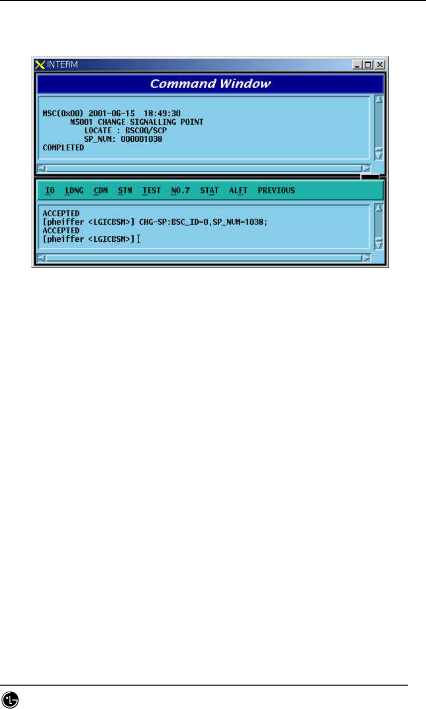
4.6.2.3. Change of Local Switching Office Signaling Point
It changes Signaling Point of Local Switching Office.
Command CHG-SP-INFO:BSC_ID=a, SP_NUM=b
STAREX-IS BSM Manual
Page:467(877)
Issue:1.
0
SMD-011-PMA210
b = SP Number ( 00 ~ 65535 )
Input CHG-SP-INFO:BSC_ID=0,SP_NUM=1038
Output
Fig. 4.6-3 Change of Remote Switching Office Signaling Point
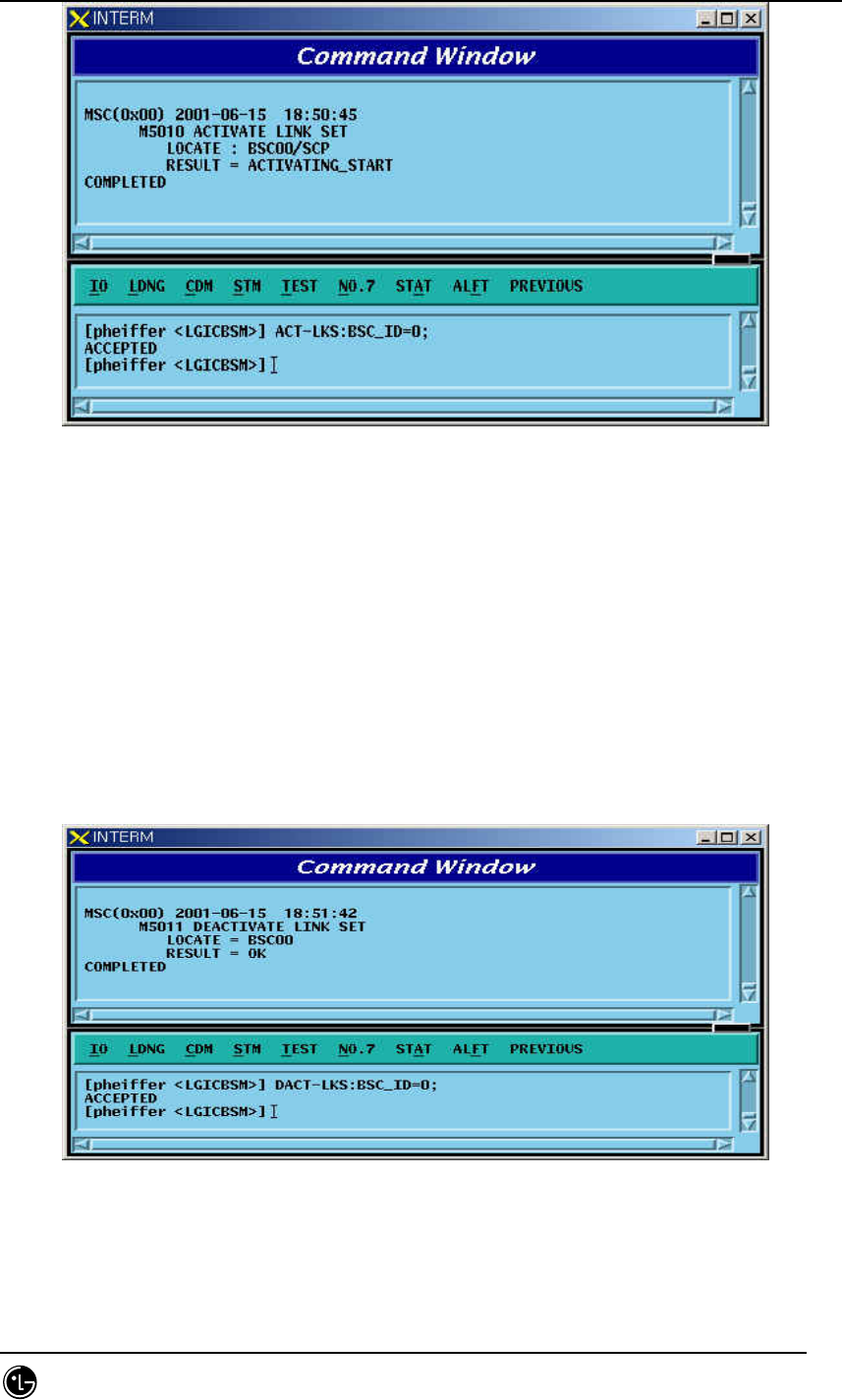
4.6.2.4. Activation of Signaling Link Set
Signaling Link Set indicates an aggregation of signaling links(Max 16 units). Activation
of Signaling Link Set is to put all the defined Signaling Links in a in-service status.
Command ACT-LKS:BSC_ID=a
a = BSC Number ( 00 ~ 11)
Input ACT-LKS:BSC_ID=0;
Output
STAREX-IS BSM Manual
Page:468(877)
Issue:1.
0
SMD-011-PMA210
Fig. 4.6-4 Activation of Signaling Link Set
4.6.2.5. Deactivation of Signaling Link Set
Function that puts all the defined Signaling Links in out-of-service status
Command DACT-LKS:BSC_ID=a;
a = BSC Number ( 00 ~ 01 )
Input DACT-LKS:BSC_ID= a;
Output
Fig. 4.6-5 Deactivation of Signaling Link Set
STAREX-IS BSM Manual
Page:469(877)
Issue:1.
0
SMD-011-PMA210
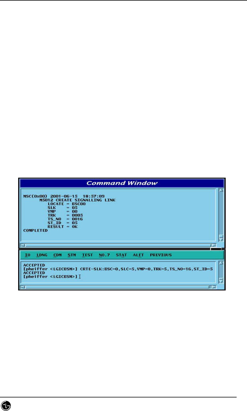
4.6.2.6. Signaling Link Generation
Signaling Link is the concept combing Signaling Data Link with Signaling Terminal. It
connects Intra-Switching Office Signaling Point to local switching Office Signaling
Point, and can define 16 units of Signaling Link. The definition of Signaling Link is used
to expand the number of Signaling Links. Before Signaling Link is defined, first of all,
Signaling Terminal and Signaling Data Link to be defined as Signaling Link should have
been defined.
Command CRTE-SLK:BSC=a, SLK=b, VMP=c, TRK=d, TS_NO = e, ST_ID =f;
a = BSC Number ( 00 ~ 11 )
b = Signalling Link Code ( 00 ~ 15 )
c = VMP ( 00 ~ 07 )
d = Trunk Number ( 00 ~ 16 )
e = Time Slot Number ( 00 ~ 31)
f = Signalling Terminal ( 1 ~ 16)
Input CRTE-SLK:BSC=0, SLK =5, VMP = 00, TRK = 5 TS_NO=16, ST_ID = 5;
Output
Fig. 4.6-6 Signaling Link Create
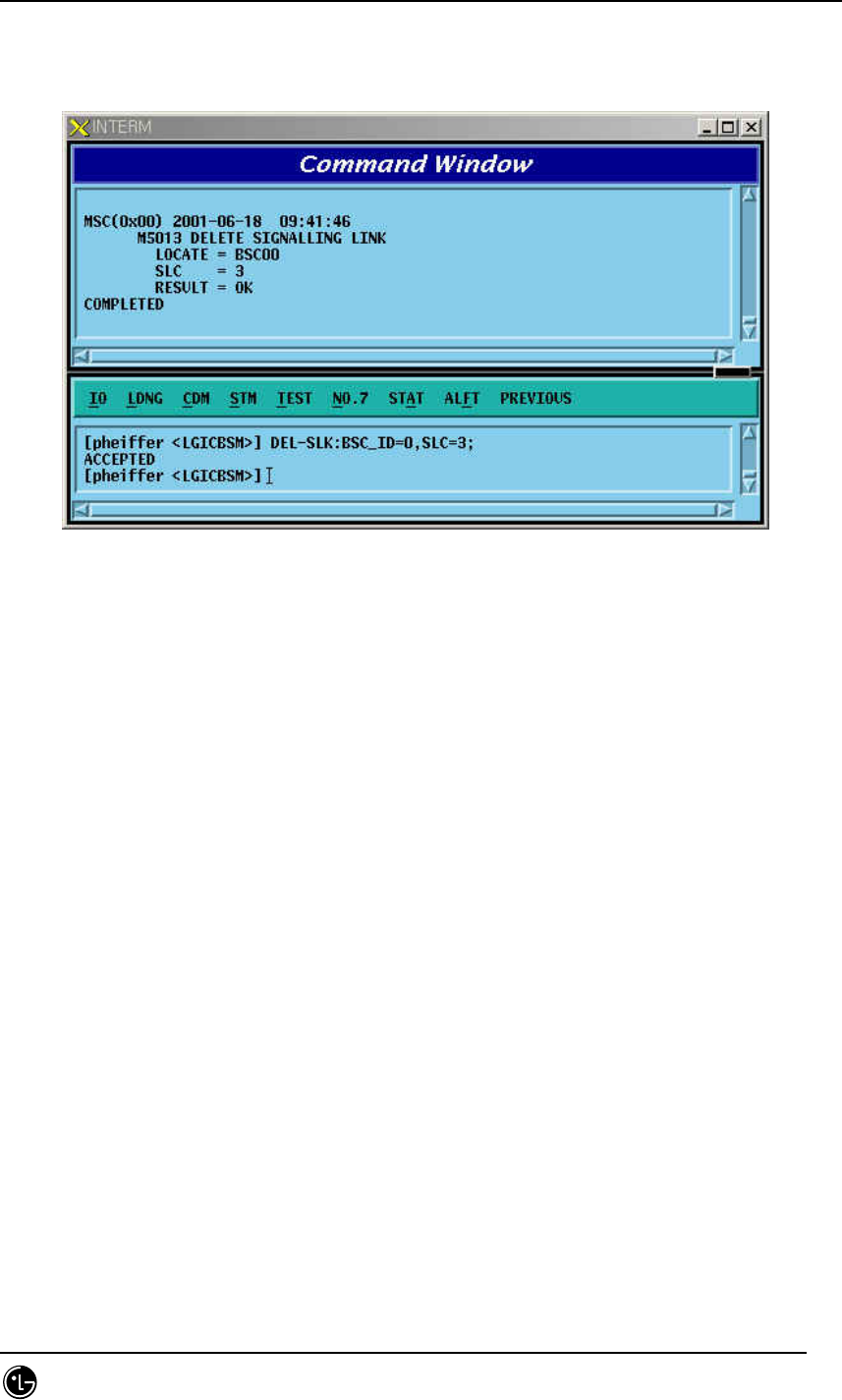
4.6.2.7. Signaling Link Deletion
Function to delete the defined Signaling Link.Before the Signaling Link is deleted, the
corresponding Signaling Link should have been successfully deactivated.
Command DEL-SLK:BSC_ID=a, SLC =b;
a = BSC Number ( 00 ~ 11 )
STAREX-IS BSM Manual
Page:470(877)
Issue:1.
0
SMD-011-PMA210
b = Signalling Link Code ( 00 ~ 15 )
Input DEL-SLK:BSC=0, SLC =3;
Output
Fig. 4.6-7 Deletion of Signaling Link
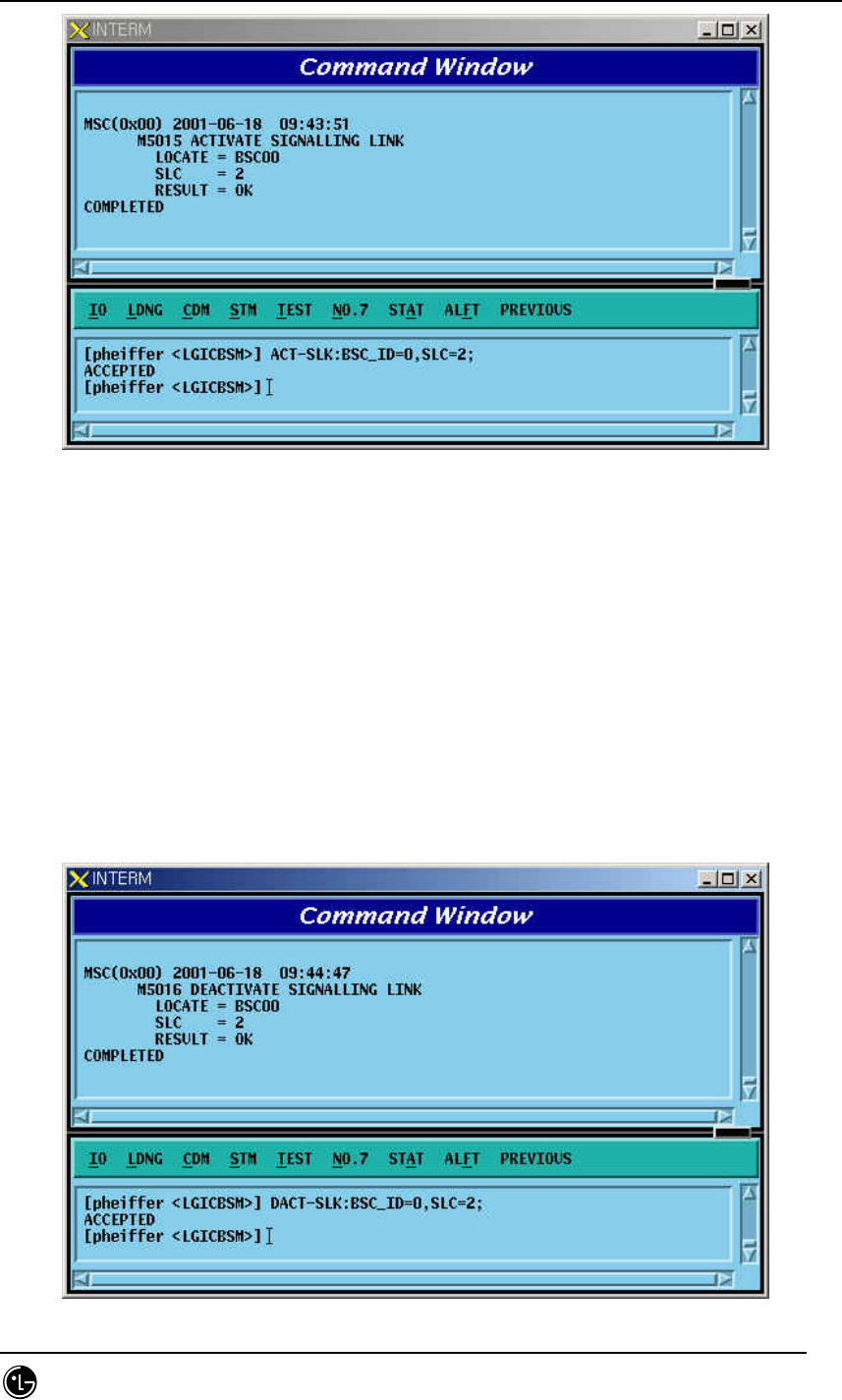
4.6.2.8. Signaling Link Activation
Function to activate a defined Signaling Link. Before activated, the corresponding
Signaling Link should have been successfully defined.
Command ACT-SLK:BSC_ID=a, SLC;
a = BSC Number ( 00 ~ 11 )
b = Signalling Link Code ( 00 ~ 15 )
Input ACT-SLK:BSC_ID=0, SLC=2;
Display
STAREX-IS BSM Manual
Page:471(877)
Issue:1.
0
SMD-011-PMA210
Fig. 4.6-8 Activation of Signaling Link
4.6.2.9. Signaling Link Deactivation
Function to deactivate the activated Signaling Link.
Command DACT-SLK:BSC=a, SLC=b;
a = BSC Number ( 00 ~ 11 )
b = Signalling Link Code ( 00 ~ 15 )
Input DACT-SLK:BSC_ID=0, SLC = 2;
Output
STAREX-IS BSM Manual
Page:472(877)
Issue:1.
0
SMD-011-PMA210
Fig. 4.6-9 Deactivation of Signaling Link
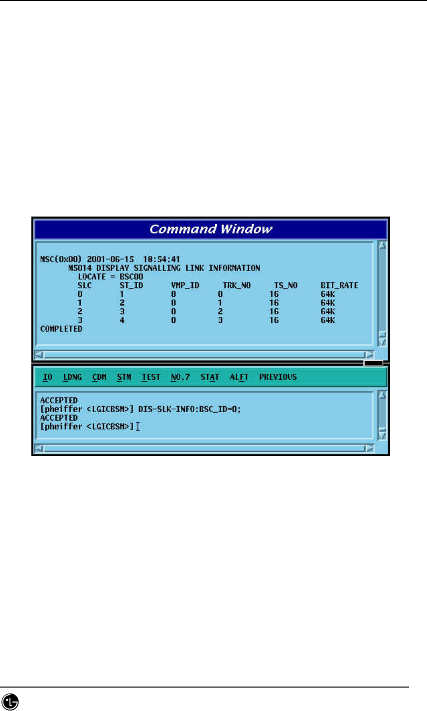
4.6.2.10. Signaling Link Information Display
Function to display information on Signaling Terminal, Signaling Data Link and Bit_Rate
connected to Signaling Link. It can display information on entire Signaling Links and on
Signaling Link designated.
Command DIS-SLK-INFO:BSC_ID=a;
a = BSC Number ( 00 ~ 15 )
Input DIS-SLK-INFO:BSC_ID = 0;
Output
Fig. 4.6-10 Signaling Link Information Display
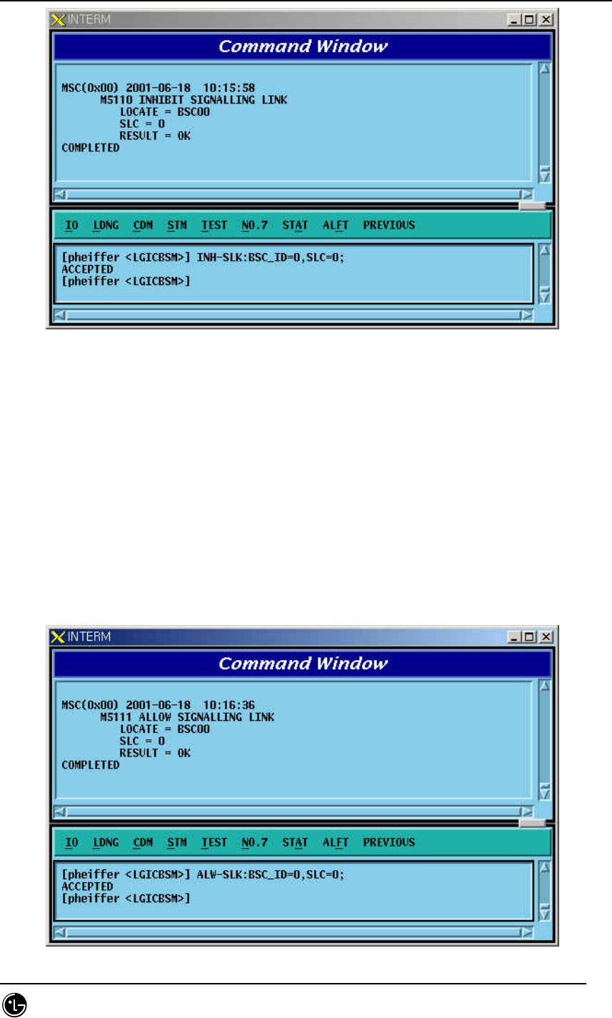
4.6.2.11. Signaling Link Inhibition
It inhibits the use of presently defined Signaling Link.
Command INH-SLK:BSC_ID=0, SLC =0;
a = BSC Number ( 00 ~ 11 )
b = Signalling Link Code ( 00 ~ 15 )
Input INH-SLK:BSC_ID=0, SLC=0;
Output
STAREX-IS BSM Manual
Page:473(877)
Issue:1.
0
SMD-011-PMA210
Fig. 4.6-11 Signaling Link Inhibit
4.6.2.12. Signaling Link Allow
Signaling Link Allow is a function that allows the management of Signaling Link
Status inhibited in the management of Signaling Link and then change to the status
of availability.
Command ALW-SLK:BSC_ID=0, SLC =0;
a = BSC Number ( 00 ~ 11 )
b = Signalling Link Code ( 00 ~ 15 )
Input ALW-SLK:BSC_ID = 0, SLC = 0;
Output
STAREX-IS BSM Manual
Page:474(877)
Issue:1.
0
SMD-011-PMA210
Fig. 4.6-12 Signal Link Allow
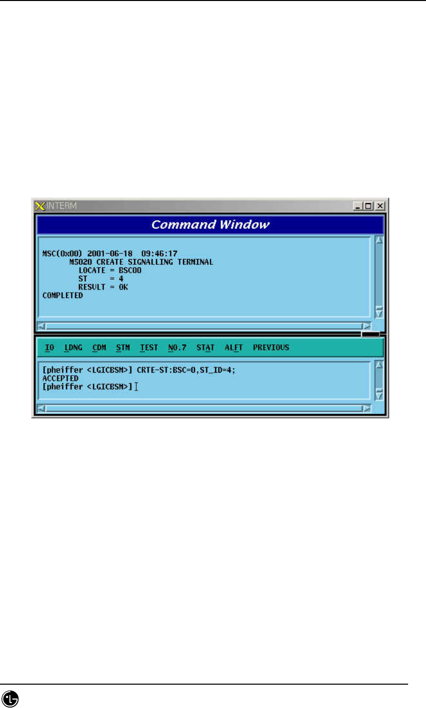
4.6.2.13. Signal Terminal Addition
Signal Terminal indicates physical name of a Channel of STPA and can define 16 units
of Signaling Terminal at a maximum. It is used to expand Signaling Terminal.
Command CRTE-ST:BSC=a, ST_ID=b;
a = BSC Number ( 00 ~ 15 )
b = Signalling Terminal ( 01 ~ 16 )
Input CRTE-ST:BSC_ID=0,ST_ID = 4;
Output
Fig. 4.6-13 Signaling Terminal Generation
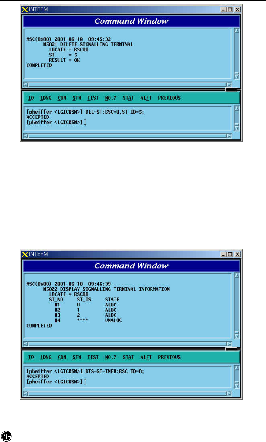
4.6.2.14. Signaling Terminal Deletion
It is used when Signaling Terminal H/W has problems or other faults occur. Before
Signaling Terminal is deleted, make sure that the corresponding Signaling Terminal is
connected to Signaling Link.
Command DEL-ST:BSC=a, ST_ID =b;
a = BSC Number ( 00 ~ 11 )
b = Signalling Terminal ( 01 ~ 16 )
Input DEL-ST:BSC_ID=0,ST_ID = 5;
Output
STAREX-IS BSM Manual
Page:475(877)
Issue:1.
0
SMD-011-PMA210
Fig. 4.6-14 Signaling Terminal Deletion
4.6.2.15. Signaling Terminal Information Display
Function to display information about if it is linked with signaling link to a specific
Signaling Terminal or all the Signaling Terminals.
Command DIS-ST-INFO:BSC_ID =a;
a = BSC Number ( 00 ~ 11 )
Input DIS-ST-INFO:BSC_ID = 0;
Output
Fig. 4.6-15 Display of Signaling Terminal Information
STAREX-IS BSM Manual
Page:476(877)
Issue:1.
0
SMD-011-PMA210
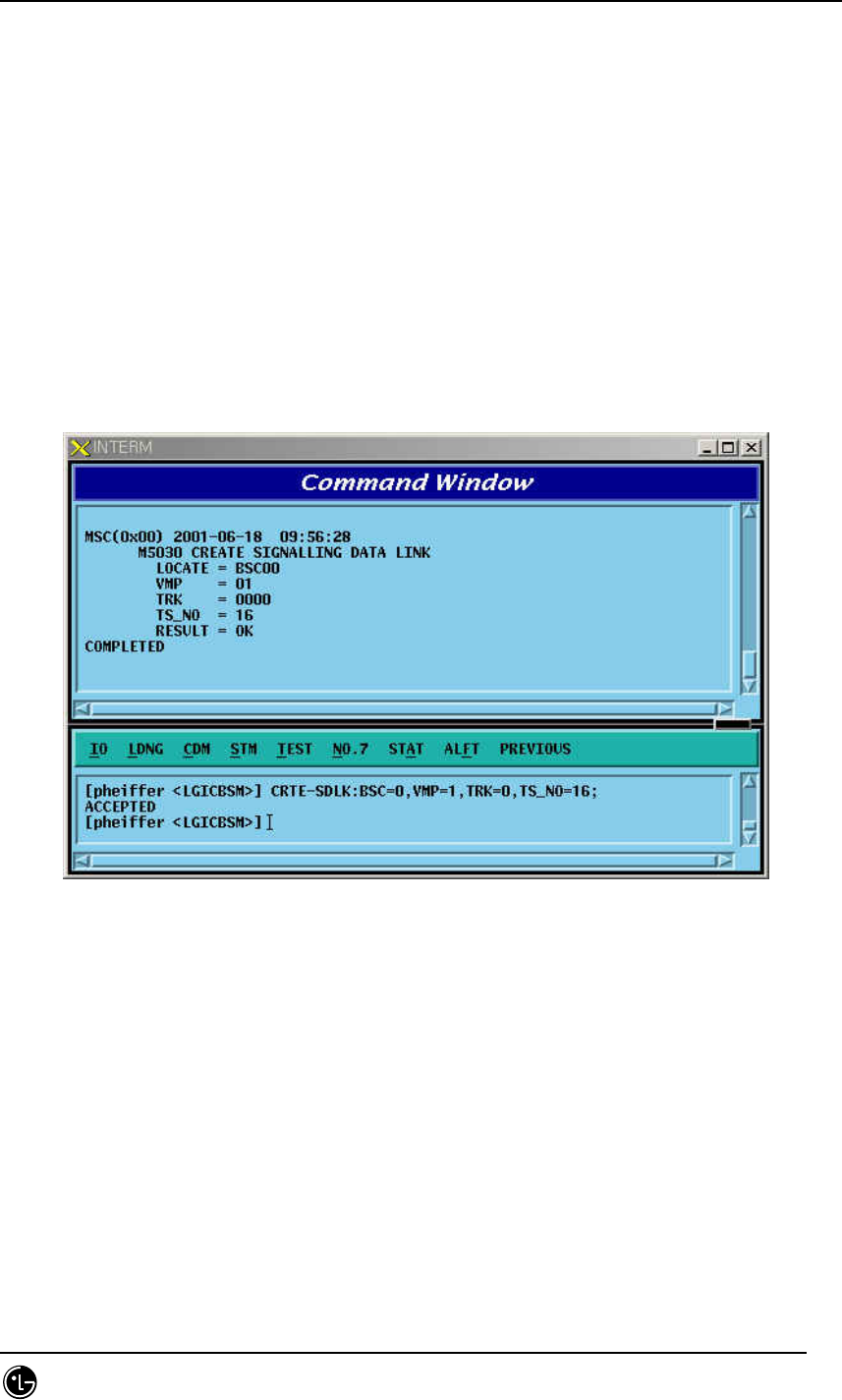
4.6.2.16. Signaling Data Link Addition
Signaling Data Link indicates Trunk Number to allocate as Signaling Link and is used
to expand Signaling Data Link.
Command CRTE-SDLK: BSC =a, VMP_ID=b, TRK= c ,TS_NO=d;
a = BSC Number ( 00 ~ 11 )
b = VMP Number( 00 ~ 07 )
c = TRUNK Number( 00 ~ 16 )
d = Time Slot Number( 00 ~ 31 )
Input CRTE-SDLK: BSC_ID=0, VMP_ID=1, TRK=0 , TS_NO=16;
Output
Fig. 4.6-16 Signaling Data Link Generation
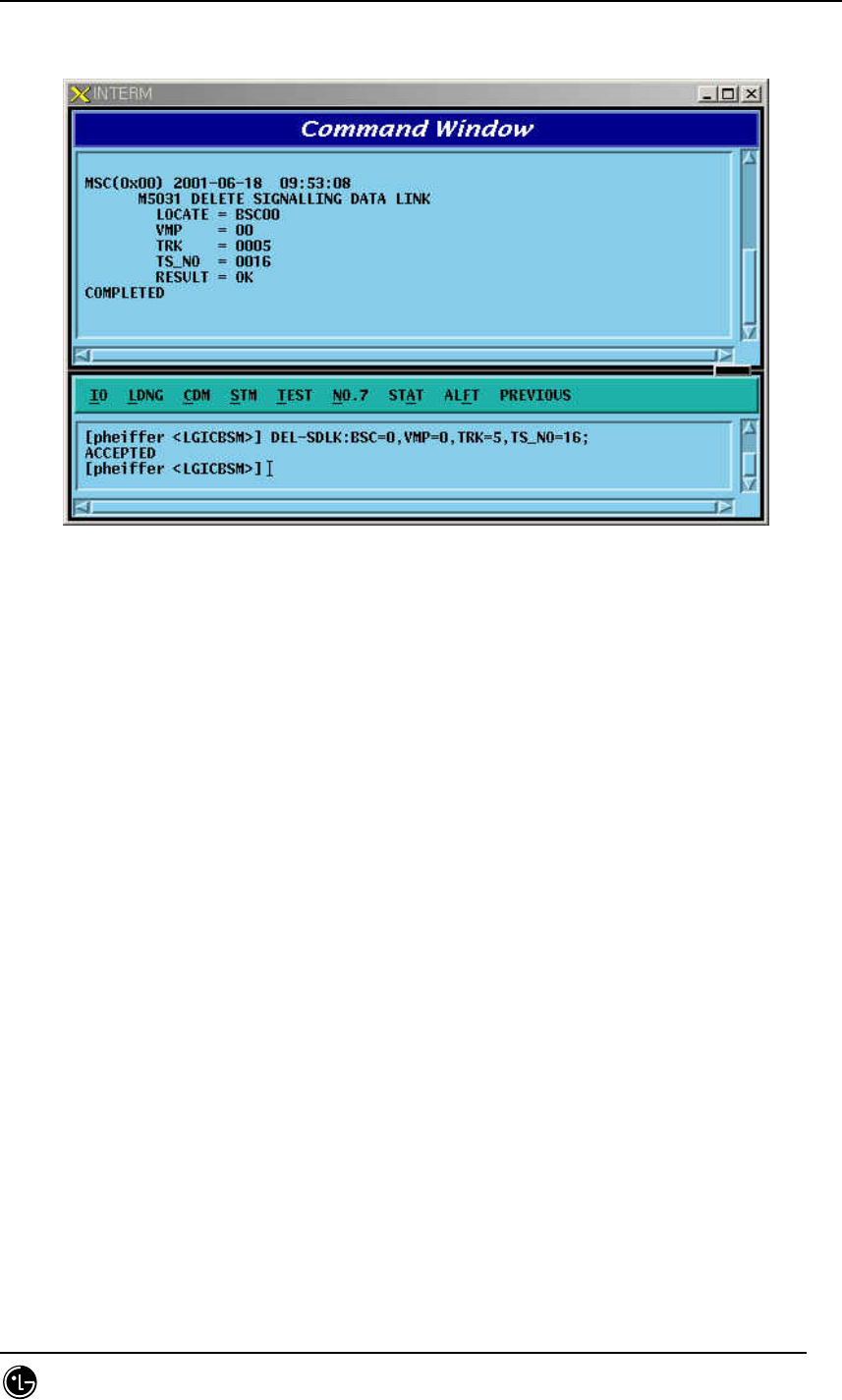
4.6.2.17. Signaling Data Link Deletion
It is used when Signaling Data Link H/W is defective or other problems occur.Before
deleting the Signaling Data Link, make sure that corresponding Signaling Data Link is
allocated to Signal Link and then delete.
Command DEL-SDLK;BSC=a, VMP=b, TRK=c, TS_NO=d;
a = BSC Number ( 00 ~ 11 )
b = VMP Number( 00 ~ 07 )
c = TRUNK Number( 00 ~ 16 )
d = Timer Slot Number( 00 ~ 31 )
STAREX-IS BSM Manual
Page:477(877)
Issue:1.
0
SMD-011-PMA210
Input DEL-SDLK:BSC=0, VMP=0, TRK= 5, TS_NO = 16;
Output
Fig. 4.6-17 Signaling Data Link Deletion
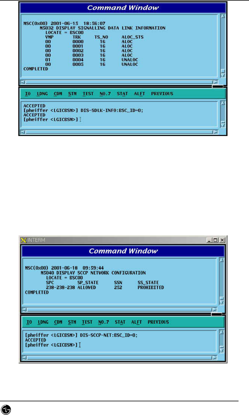
4.6.2.18. Signaling Data Link Information Display
Function to display information on the defined Signaling Data Link and the status
connected to Signaling Link.
Command DIS-SDLK-INFO: BSC_ID = a;
a = BSC Number ( 00 ~ 11 )
Input DIS-SDLK-INFO: BSC_ID=0;
Output
STAREX-IS BSM Manual
Page:478(877)
Issue:1.
0
SMD-011-PMA210
Fig. 4.6-18 Signaling Data Link Information Display
4.6.2.19. SCCP Network Configuration Data Display
Function to display SCCP Network Configuration Data for Intra-Switching Office
Signaling Point, local Switching Office Signaling Point, and each sub-system.
Command DIS-SCCP-NET:BSC_ID=a;
a = BSC Number ( 00 ~ 11 )
Input DIS-SCCP-NET:BSC_ID=0;
Output
Fig. 4.6-19 SCCP Network Configuration Data Display
STAREX-IS BSM Manual
Page:479(877)
Issue:1.
0
SMD-011-PMA210
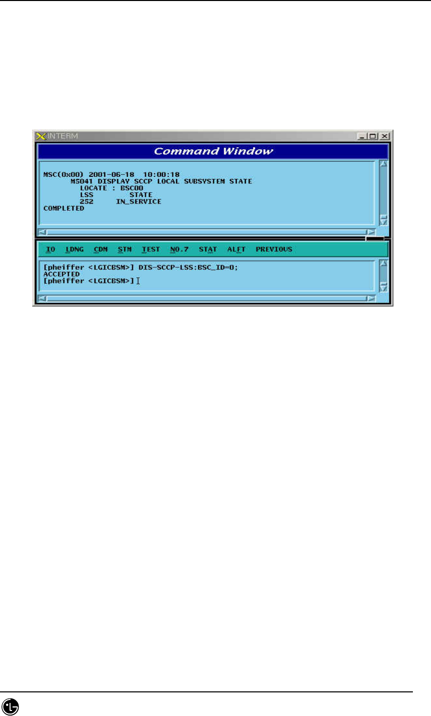
4.6.2.20. SCCP Local Subsystem State Data Display
Function to display State related to Local Exchange Sub-system defined at Local
Exchange Signaling Point
Command DIS-SCCP-LSS:BSC_ID =a;
a = BSC Number ( 00 ~ 16 )
Input DIS-SCCP-LSS:BSC_ID = 0;
Output
Fig. 4.6-20 SCCP Local Subsystem State Data Display
4.6.2.21. Signaling Link Status Display
Function to display a designated Signaling Link Status, Activate Status of Signaling
Link, Inhibit Status of Intra switching office Signaling Link, and Inhibit Status of local
Switching Office.
Command DIS-SLK-STS:BSC_ID = a, SLC = b;
a = BSC Number ( 00 ~ 11)
b = Signalling Number Code ( 00 ~ 16 )
Input DIS-SLK-STS:BSC_ID = 0, SLC=0;
Output