LG Electronics USA 3G1XINBTS STAREX-IS 1900 Indoor BTS User Manual STAREX IS User s Manual
LG Electronics USA STAREX-IS 1900 Indoor BTS STAREX IS User s Manual
Contents
Users Manual Part B
STAREX-IS BSM Manual
Page:199(877)
Issue:1.
0
SMD-011-PMA210
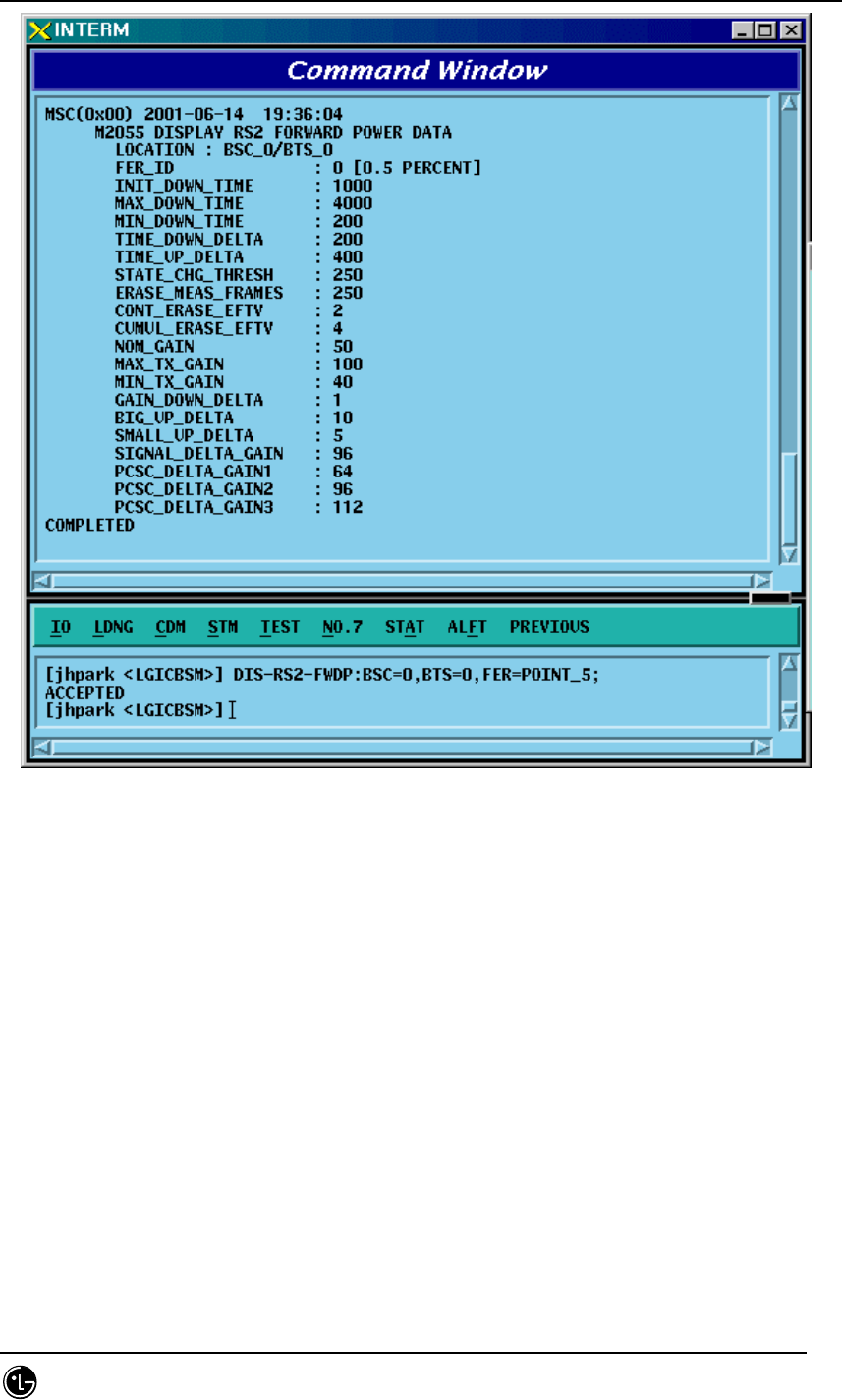
Fig. 4.3-27 Forward Link Power Management Information (RS2) Verification

STAREX-IS BSM Manual
Page:200(877)
Issue:1.
0
SMD-011-PMA210
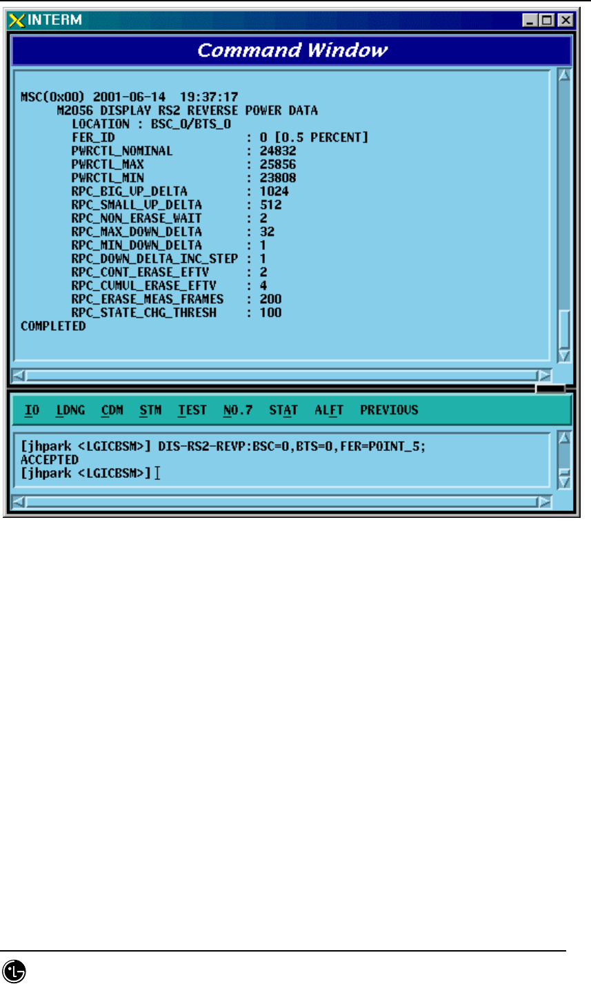
4.3.2.6. Backward Link Power Management Information (RS2)
Verification
Rate Set 2 transmits data at the speed of 14400,7200,3600,1800 bps. Input the
following command to check the parameter information for RS2 Backward Link Power
Management. Among the input values, FER (Frame Error Rate) has the value ranging
from 0.5%, 1 to 5%.
• Command DIS-RS2-REVP: BSC=a, BTS=b, FER=c;
a : BSC Number(0~11)
b: BTS Number(0~47)
c:FER
(POINT_5/PERCENT_1/PERCENT_2/PERCENT_3/PERCENT_4/PERCET_5)
• Input DIS-RS2-REVP: BSC=0, BTS=0, FER=POINT_5;
• Output
STAREX-IS BSM Manual
Page:201(877)
Issue:1.
0
SMD-011-PMA210
Fig. 4.3-28 Backward Link Power Management Information (RS2) Verification

STAREX-IS BSM Manual
Page:202(877)
Issue:1.
0
SMD-011-PMA210
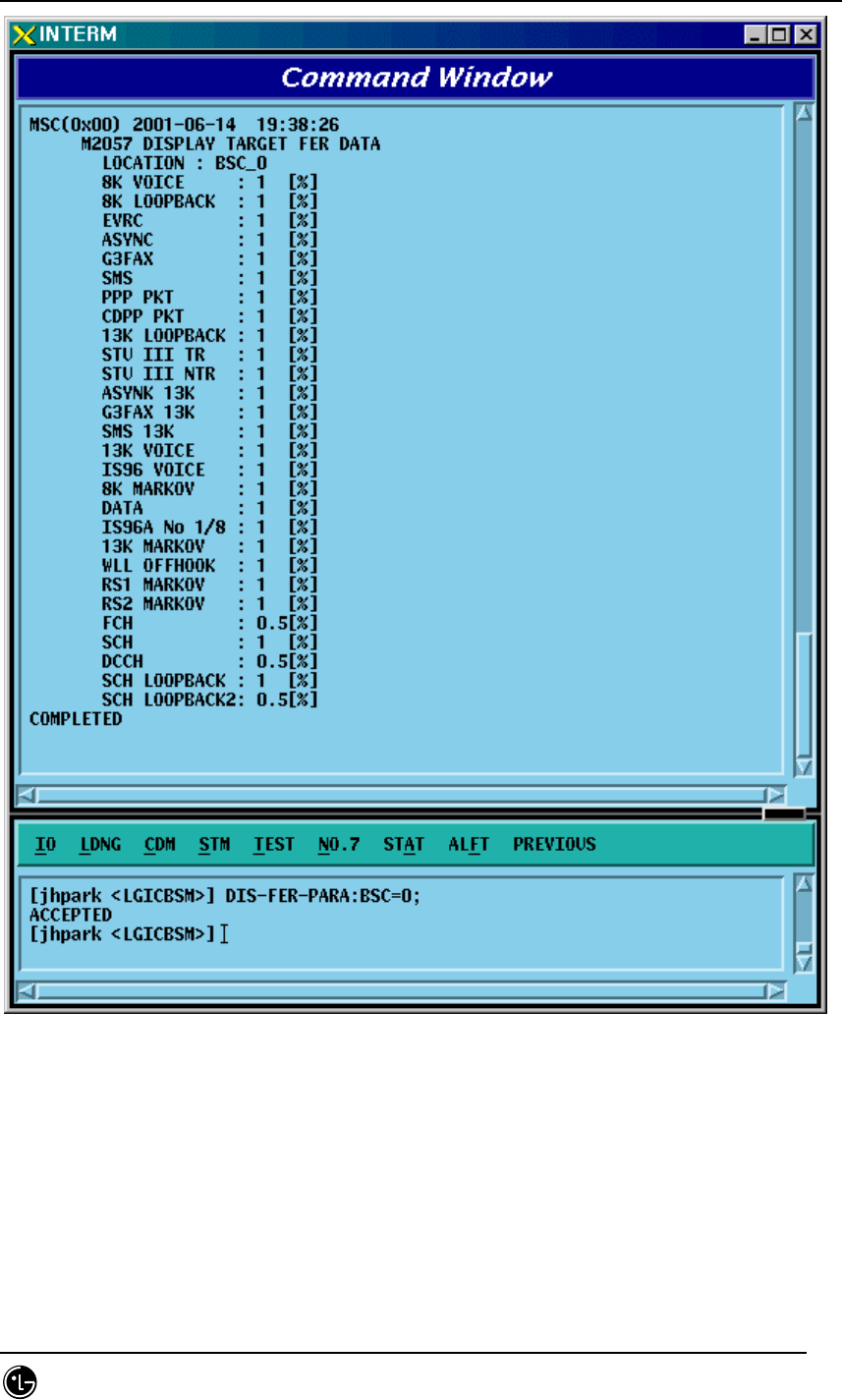
4.3.2.7. Service Option FER Verification
Target FER can be designated by the Service Option. Input the following command to
display this information. In the next display, 1% Target FER is applied for the "8K
VOICE" Service Option and for this, the following power management information is
used: RS1 forward link power management information, RS1 backward link power
management information, RS2 forward link power management information, and RS2
backward (or reverse-direction) link power management information.
• Command DIS-FER-PARA: BSC=a;
a : BSC Number(0~11)
• Input DIS-FER-PARA: BSC=0;
• Output
STAREX-IS BSM Manual
Page:203(877)
Issue:1.
0
SMD-011-PMA210
Fig. 4.3-29 Service Option FER Verification
STAREX-IS BSM Manual
Page:204(877)
Issue:1.
0
SMD-011-PMA210
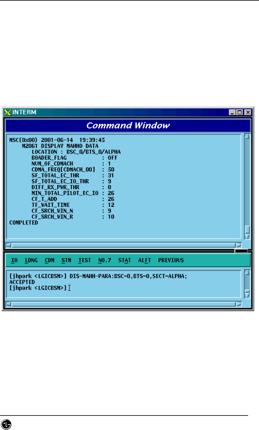
4.3.2.8. MAHHO Verification
• Command DIS-MAHH-PARA: BSC=a, BTS=b, SECT=c;
a : BSC Number(0~11)
b: BTS Number(0~47)
c: Sector Id .(ALPHA/BETA/GAMMA)
• Input DIS-MAHH-PARA: BSC=0,BTS=0,SECT=ALPHA;
• Output
Fig. 4.3-30 MAHHO Verification
STAREX-IS BSM Manual
Page:205(877)
Issue:1.
0
SMD-011-PMA210
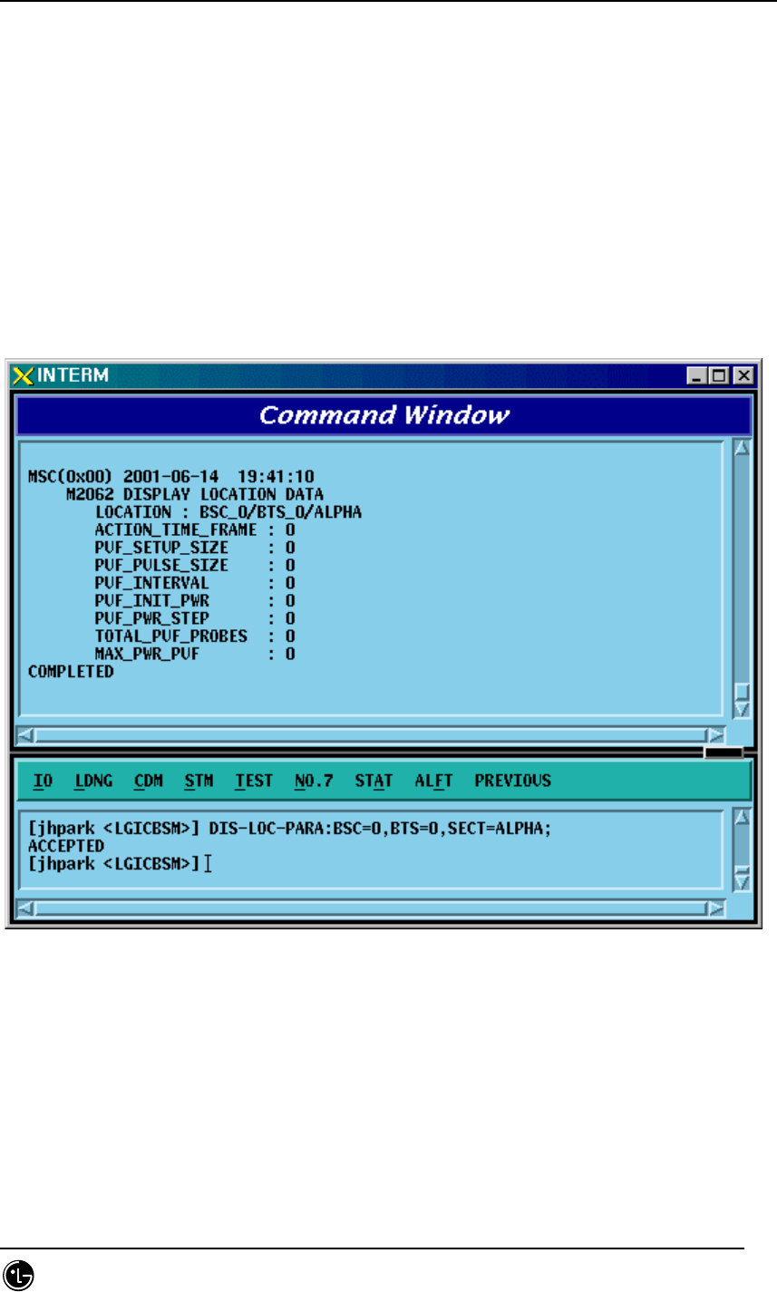
4.3.2.9. LOCATION Verification
• Command DIS-LOC-PARA: BSC=a, BTS=b, SECT=c;
a : BSC Number(0~11)
b: BTS Number(0~47)
c: Sector Id .(ALPHA/BETA/GAMMA)
• Input DIS-LOC-PARA: BSC=0,BTS=0,SECT=ALPHA;
• Output
Fig. 4.3-31 LOCATION Verification

STAREX-IS BSM Manual
Page:206(877)
Issue:1.
0
SMD-011-PMA210
4.3.2.10. SCH Verification
• Command DIS-SCH-PARA: BSC=a, BTS=b, SECT=c;
a : BSC Number(0~11)
b: BTS Number(0~47)
c: Sector Id .(ALPHA/BETA/GAMMA)
• Input DIS-SCH-PARA: BSC=0,BTS=0,SECT=ALPHA;
• Output
Fig. 4.3-32 SCH Verification
STAREX-IS BSM Manual
Page:207(877)
Issue:1.
0
SMD-011-PMA210
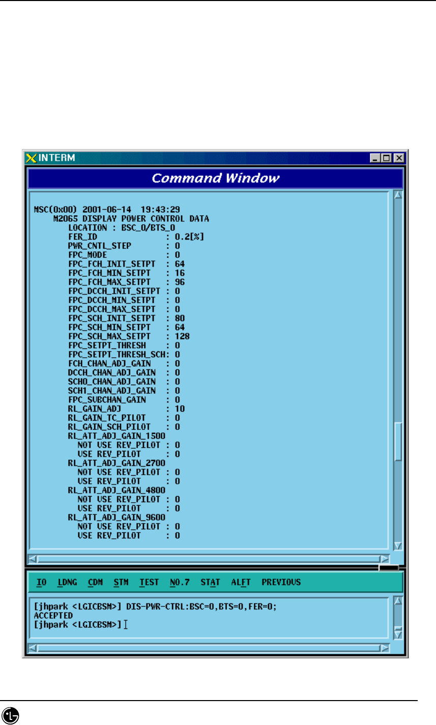
4.3.2.11. Power Control Data Verification
• Command DIS-PWR-CTRL: BSC=a, BTS=b, FER=c;
a : BSC Number(0~11)
b: BTS Number(0~47)
c: FER (0~30)
• Input DIS-PWR-CTRL: BSC=0, BTS=0,FER=0;
• Output

STAREX-IS BSM Manual
Page:208(877)
Issue:1.
0
SMD-011-PMA210
Fig. 4.3-33 Power Control Data Verification
STAREX-IS BSM Manual
Page:209(877)
Issue:1.
0
SMD-011-PMA210
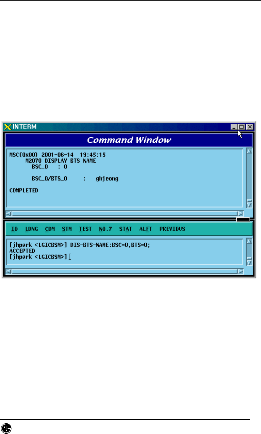
4.3.2.12. BTS Name Display
Input the following command to display the BTS name:
• Command DIS-BTS-NAME: BSC=a, BTS=b;
a : BSC Number(0~11)
b: BTS Number(0~47)
• Input DIS-BTS-NAME: BSC=0, BTS=0;
• Output
Fig. 4.3-34 BTS Name Display
STAREX-IS BSM Manual
Page:210(877)
Issue:1.
0
SMD-011-PMA210
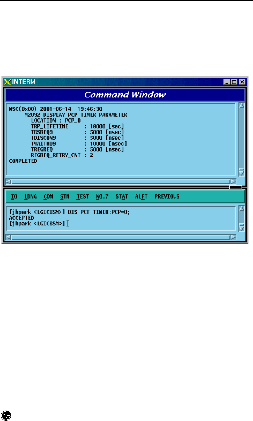
4.3.2.13. PCP Timer Information Verification
• Command DIS-PCF-TIMER:PCP =a;
a : PCP Number(0~2)
• Input DIS-PCF-TIMER: PCP=0;
• Output
Fig. 4.3-35 PCP Timer Information Verification
STAREX-IS BSM Manual
Page:211(877)
Issue:1.
0
SMD-011-PMA210
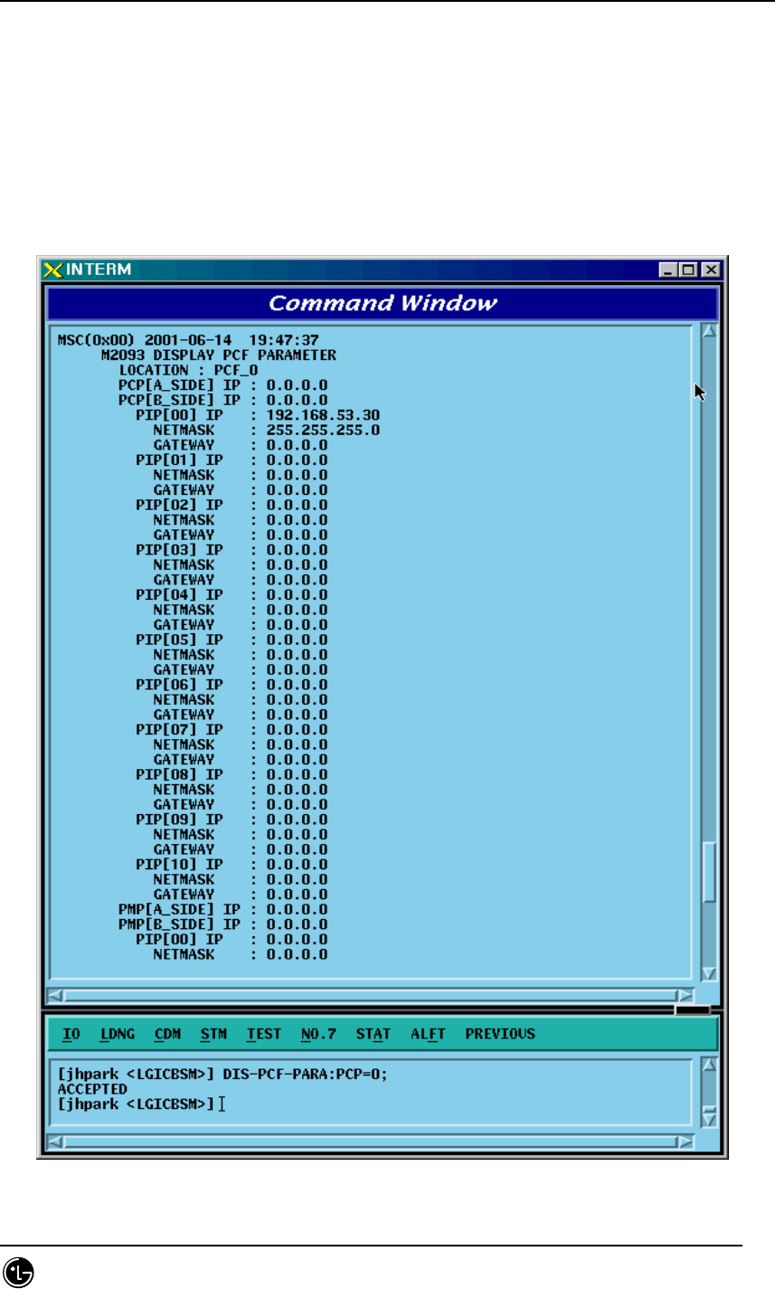
4.3.2.14. PCF Parameter Information Verification
• Command DIS-PCF-PARA :PCP =a;
a : PCP Number(0~2)
• Input DIS-PCF-PARA: PCP=0;
• Output
Fig. 4.3-36 PCF Parameter Information Verification
STAREX-IS BSM Manual
Page:212(877)
Issue:1.
0
SMD-011-PMA210
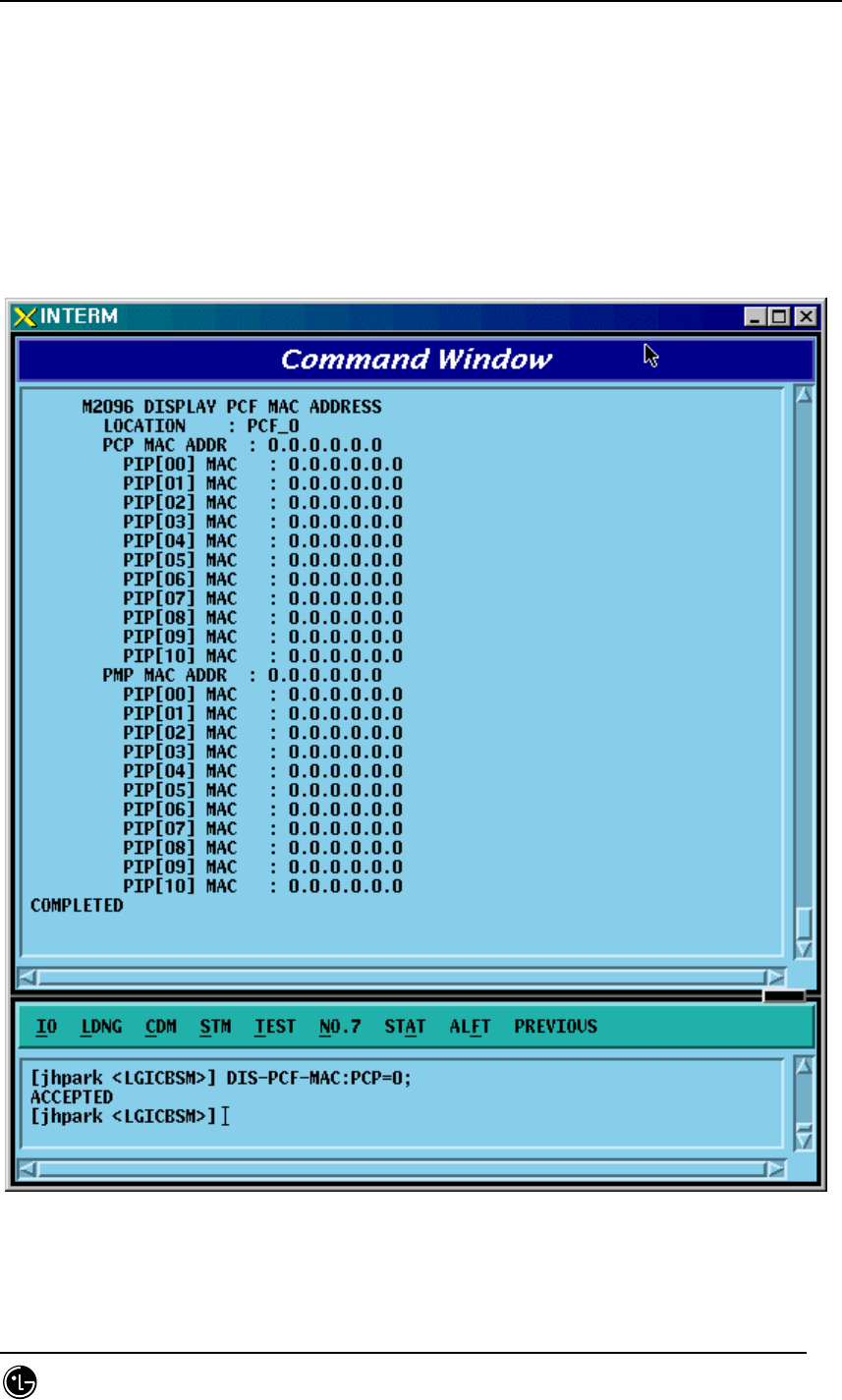
4.3.2.15. PCF MAC ADDRESS Information Verification
• Command DIS-PCF-MAC :PCP =a;
a : PCP Number(0~2)
• Input DIS-PCF-MAC: PCP=0;
• Output
Fig. 4.3-37 PCF MAC ADDRESS Information Verification
STAREX-IS BSM Manual
Page:213(877)
Issue:1.
0
SMD-011-PMA210
4.3.3. NETWORK Information Display
(Display_Parameter_Information_3)
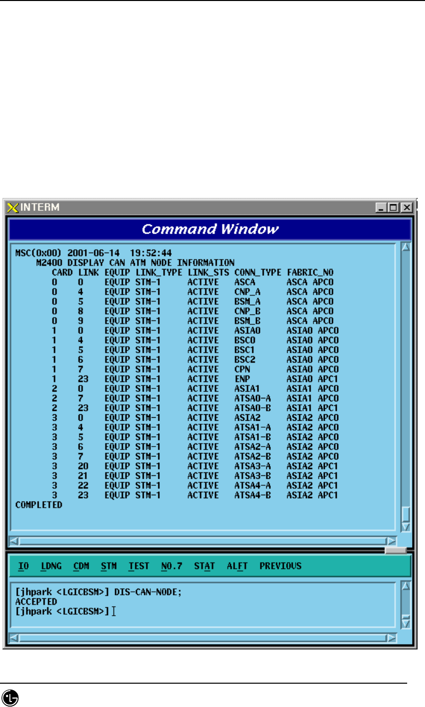
4.3.3.1. CAN ATM NODE Information Display
• Command DIS-CAN-NODE;
• Output

STAREX-IS BSM Manual
Page:214(877)
Issue:1.
0
SMD-011-PMA210
Fig. 4.3-38 CAN ATM NODE Information Display
STAREX-IS BSM Manual
Page:215(877)
Issue:1.
0
SMD-011-PMA210
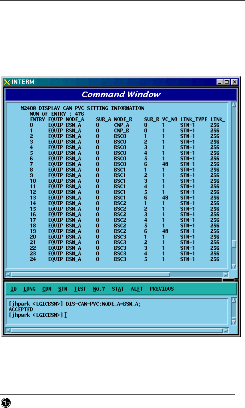
4.3.3.2. CAN PVC SETTING Information Display
• Command DIS-CAN-PVC;NODE_A=a;
• Input DIS-CAN-PVC: NODE_A=BSM_A;
a: BSM_A,BSM_B, BSC (0~11)
• Output
Fig. 4.3-39 CAN PVC SETTING Information Display
STAREX-IS BSM Manual
Page:216(877)
Issue:1.
0
SMD-011-PMA210
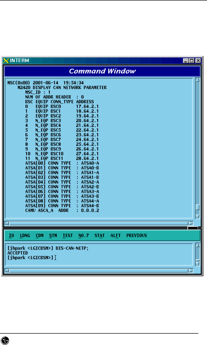
4.3.3.3. CAN NETWORK PARAMETER Information Display
• Command DIS-CAN-NETP;
• Input DIS-CAN-NETP;
• Output
Fig. 4.3-40 CAN NETWORK PARAMETER Information Display
STAREX-IS BSM Manual
Page:217(877)
Issue:1.
0
SMD-011-PMA210
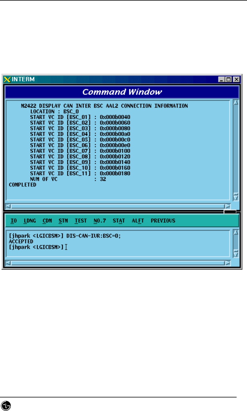
4.3.3.4. CAN INTER BSC AAL2 Setting Information Display
• Command DIS-CAN-IUR:BSC=a;
a:BSC Number (0~11)
• Input DIS-CAN-IUR:BSC=0;
• Output
Fig. 4.3-41 CAN INTER BSC AAL2 Setting Information Display
STAREX-IS BSM Manual
Page:218(877)
Issue:1.
0
SMD-011-PMA210
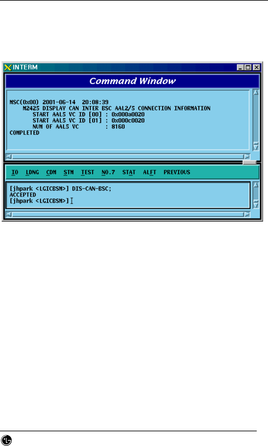
4.3.3.5. CAN INTER BSC AAL5 Setting Information Display
• Command DIS-CAN-BSC;
• Output
Fig. 4.3-42 CAN INTER BSC AAL5 Setting Information Display
STAREX-IS BSM Manual
Page:219(877)
Issue:1.
0
SMD-011-PMA210
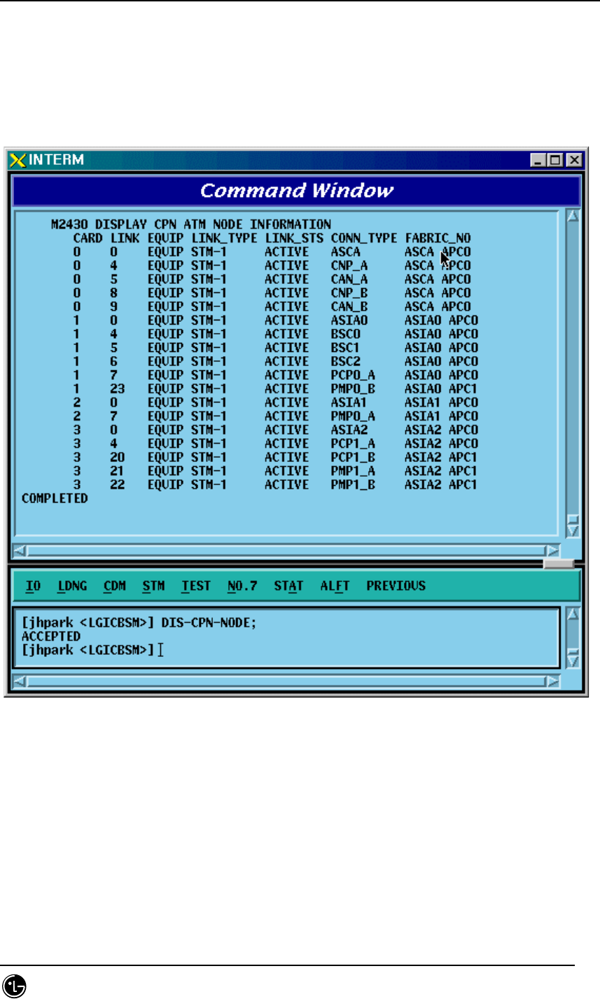
4.3.3.6. CAN ATM NODE Information Display
• Command DIS-CPN-NODE;
• Output
Fig. 4.3-43 CAN ATM NODE Information Display
STAREX-IS BSM Manual
Page:220(877)
Issue:1.
0
SMD-011-PMA210
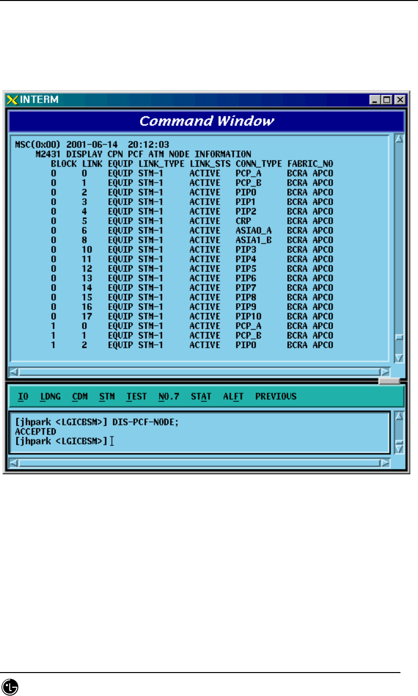
4.3.3.7. PCF ATM NODE Information Display
• Command DIS-PCF-NODE
• Output
Fig. 4.3-44 PCF ATM NODE Information Display
STAREX-IS BSM Manual
Page:221(877)
Issue:1.
0
SMD-011-PMA210
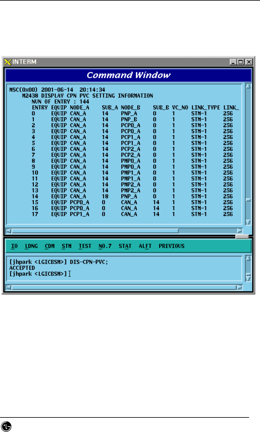
4.3.3.8. CAN PVC SETTING Information Display
• Command DIS-CPN-PVC
• Output
Fig. 4.3-45 CAN PVC SETTING Information Display
STAREX-IS BSM Manual
Page:222(877)
Issue:1.
0
SMD-011-PMA210
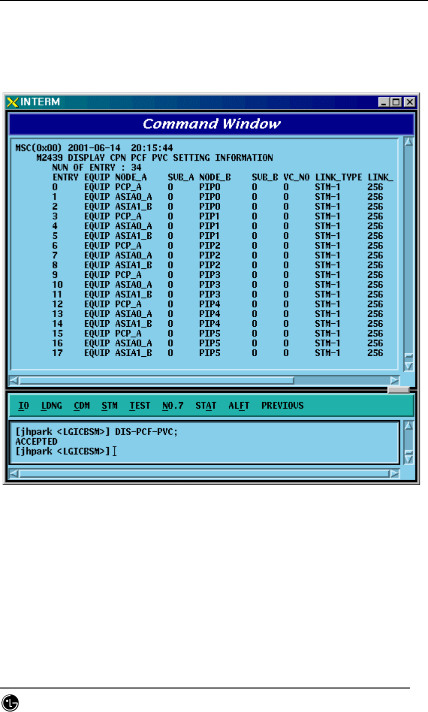
4.3.3.9. CAN PCF PVC SETTING Information Display
• Command DIS-PCF-PVC
• Output
Fig. 4.3-46 CAN PCF PVC SETTING Information Display
STAREX-IS BSM Manual
Page:223(877)
Issue:1.
0
SMD-011-PMA210
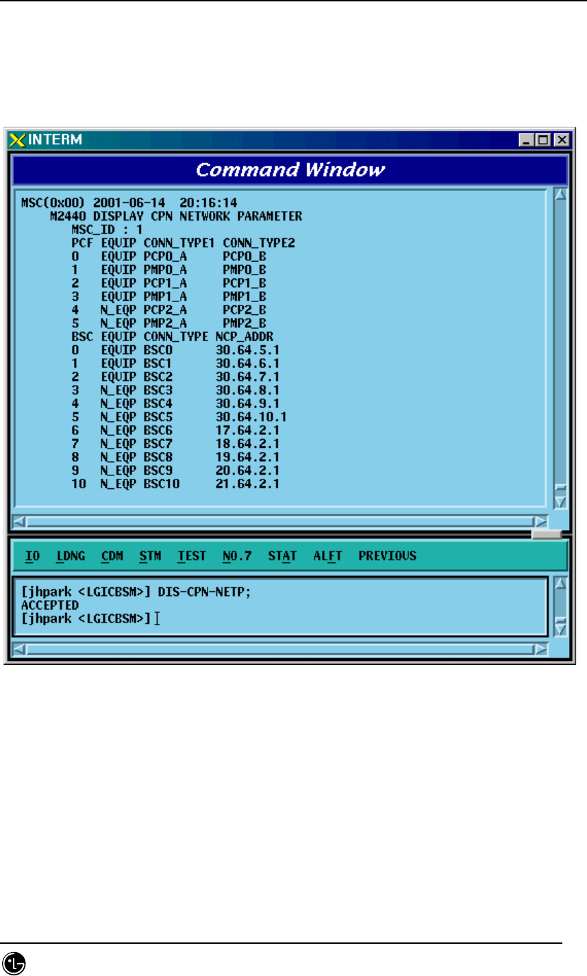
4.3.3.10. CPN METWORK PARAMETER Information Display
• Command DIS-CPN-NETP
• Output
Fig. 4.3-47 CPN METWORK PARAMETER Information Display
STAREX-IS BSM Manual
Page:224(877)
Issue:1.
0
SMD-011-PMA210
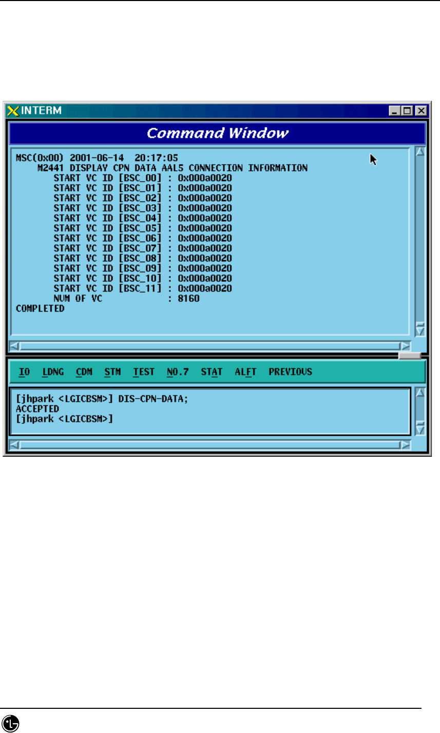
4.3.3.11. CPN DATA AAL2/5 Connection Information Display
• Command DIS-CPN-DATA;
• Output
Fig. 4.3-48 CPN DATA AAL2/5 Connection Information Display
STAREX-IS BSM Manual
Page:225(877)
Issue:1.
0
SMD-011-PMA210
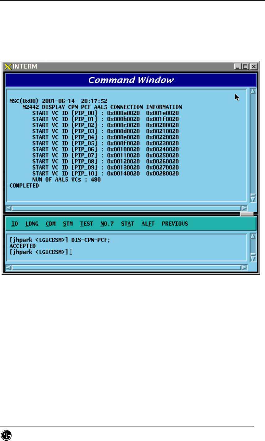
4.3.3.12. CPN PCF AAK2/5 Connection Information Display
• Command DIS-CPN-PCF;
• Output
Fig. 4.3-49 CPN PCF AAK2/5 Connection Information Display
STAREX-IS BSM Manual
Page:226(877)
Issue:1.
0
SMD-011-PMA210
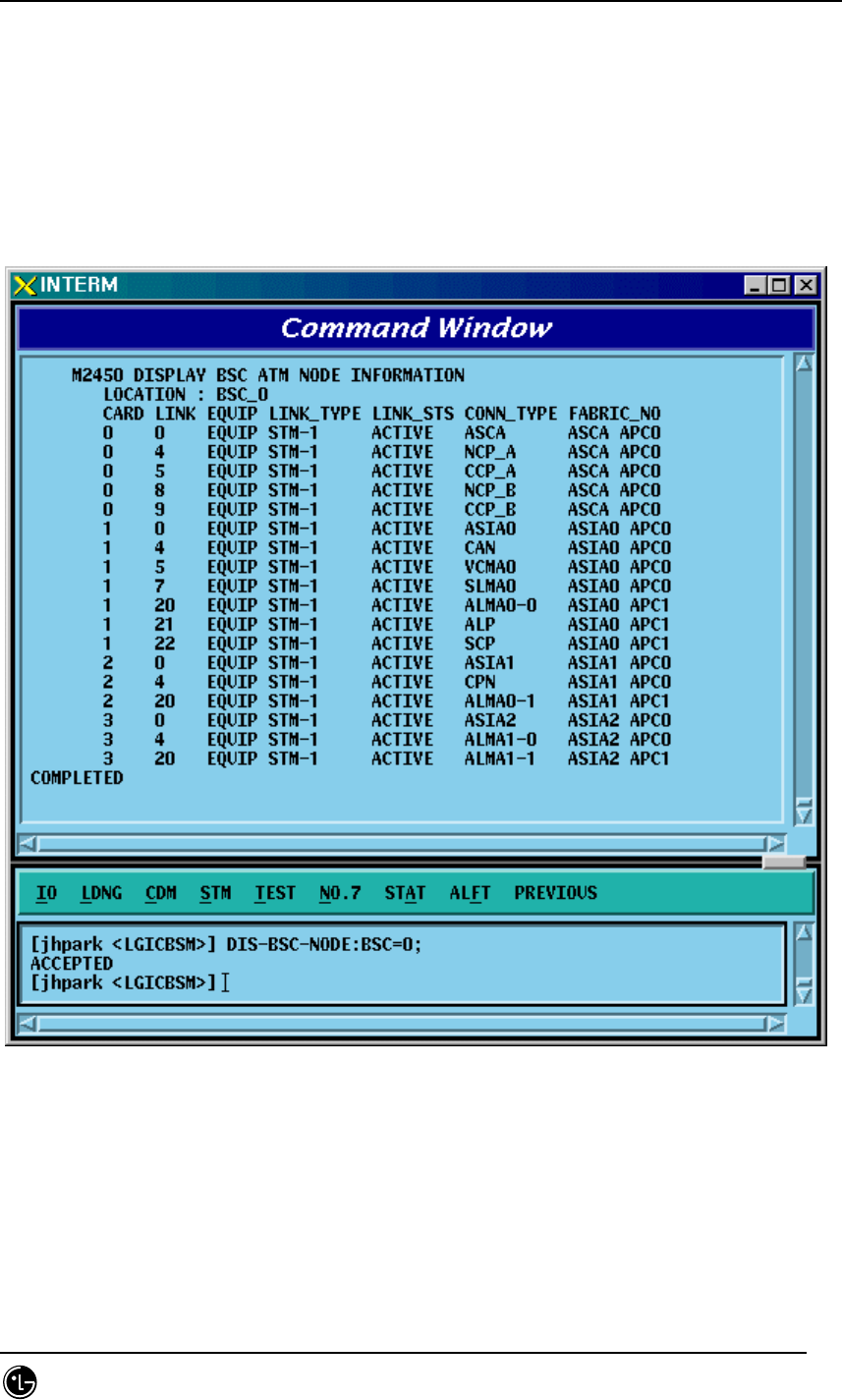
4.3.3.13. BSC ATM NODE Information Display
• Command DIS-BSC-NODE: BSC=a;
a: BSC Number (0~11)
• Input DIS-BSC-NODE: BSC=0;
• Output
Fig. 4.3-50 BSC ATM NODE Information Display
STAREX-IS BSM Manual
Page:227(877)
Issue:1.
0
SMD-011-PMA210
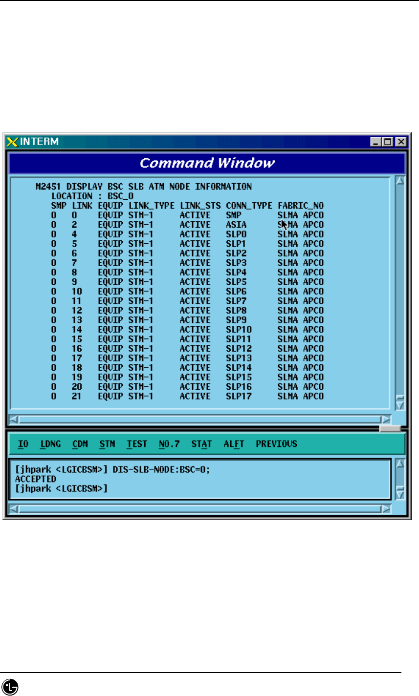
4.3.3.14. SLB ATM NODE Information Display
• Command DIS-SLB-NODE: BSC=a;
a: BSC Number (0~11)
• Input DIS-SLB-NODE: BSC=0;
• Output
Fig. 4.3-51 SLB ATM NODE Information Display
STAREX-IS BSM Manual
Page:228(877)
Issue:1.
0
SMD-011-PMA210
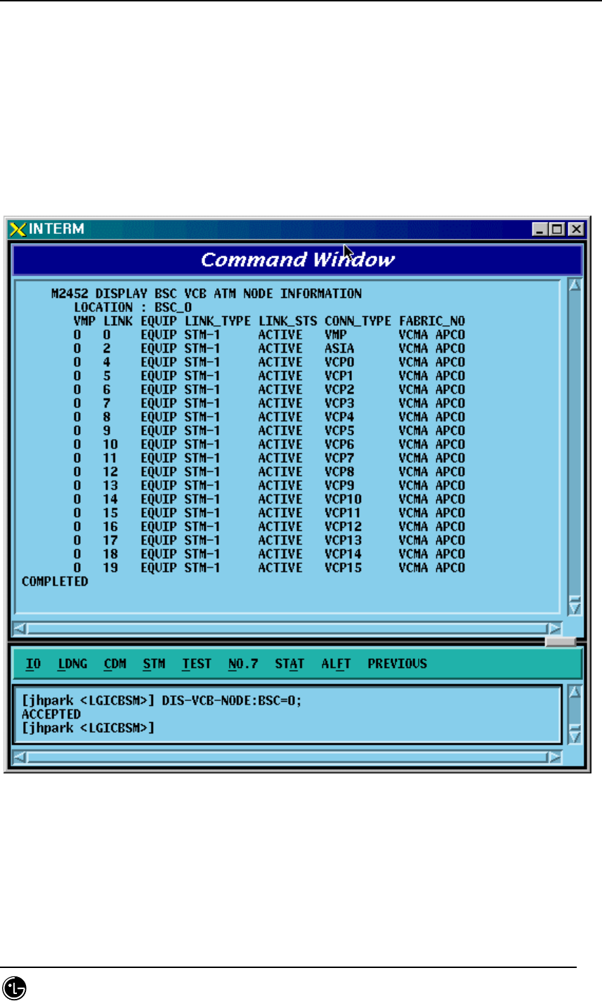
4.3.3.15. VCB ATM NODE Information Display
• Command DIS-VCB-NODE: BSC=a;
a: BSC Number (0~11)
• Input DIS-VCB-NODE: BSC=0;
• Output
Fig. 4.3-52 VCB ATM NODE Information Display
STAREX-IS BSM Manual
Page:229(877)
Issue:1.
0
SMD-011-PMA210
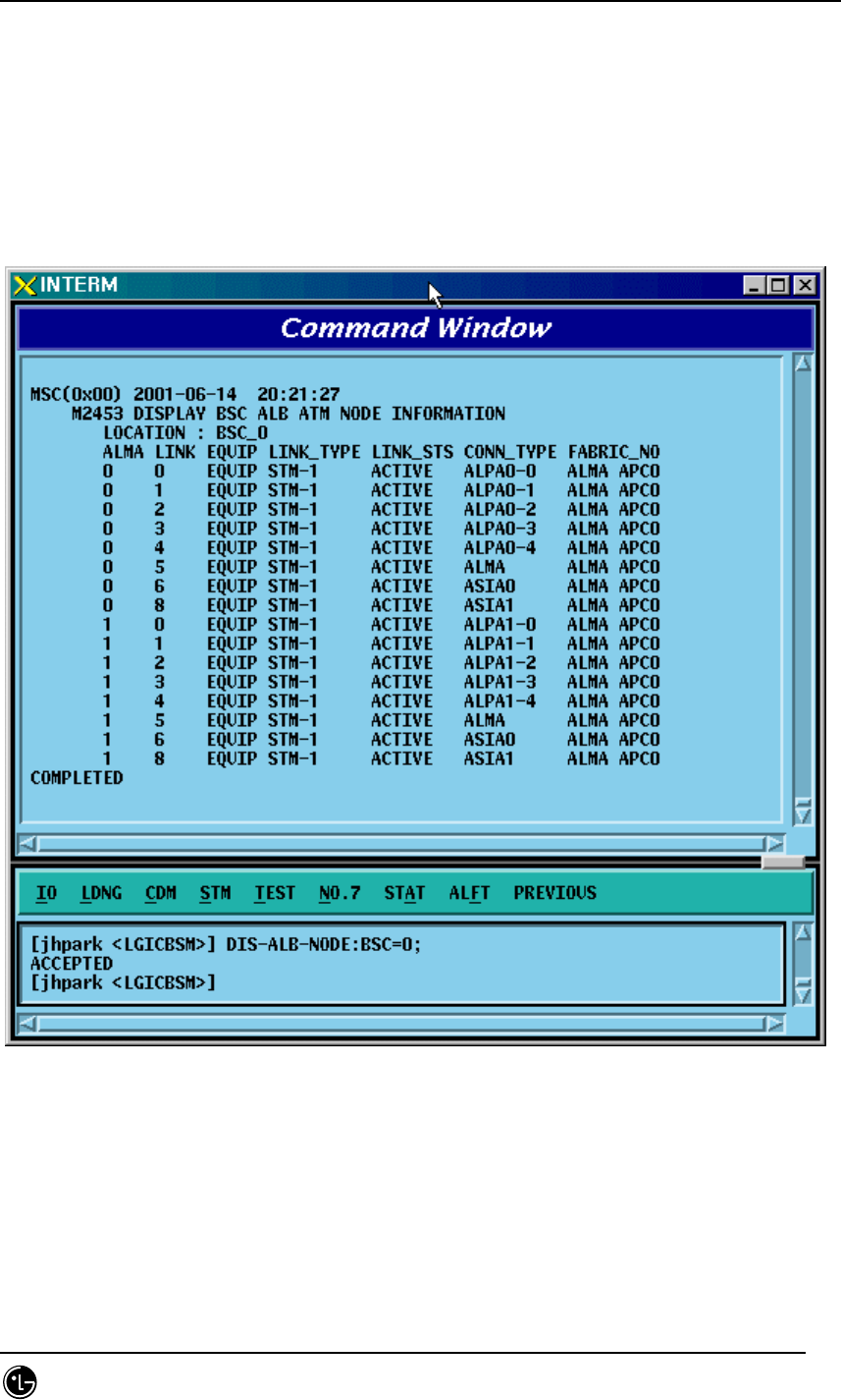
4.3.3.16. ALB ATM NODE Information Display
‘
• Command DIS-ALB-NODE: BSC=a;
a: BSC Number (0~11)
• Input DIS-ALB-NODE: BSC=0;
• Output
Fig. 4.3-53 ALB ATM NODE Information Display
STAREX-IS BSM Manual
Page:230(877)
Issue:1.
0
SMD-011-PMA210
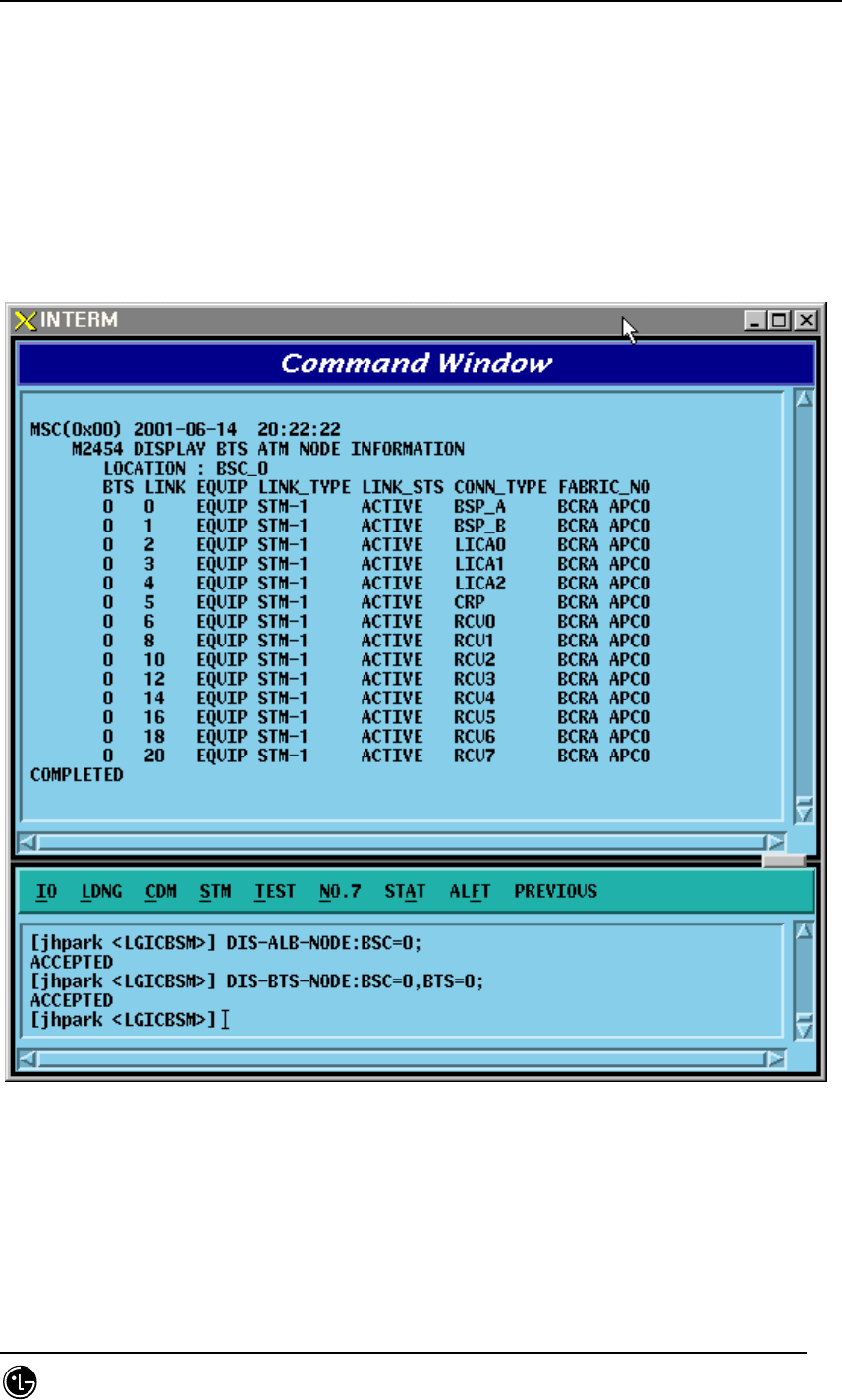
4.3.3.17. BTS ATM NODE Information Display
• Command DIS-BTS-NODE: BSC=a ,BTS=b;
a: BSC Number (0~11)
b: BTS Number (0~47)
• Input DIS-BSC-NODE: BSC=0,BTS=0;
• Output
Fig. 4.3-54 BTS ATM NODE Information Display
STAREX-IS BSM Manual
Page:231(877)
Issue:1.
0
SMD-011-PMA210
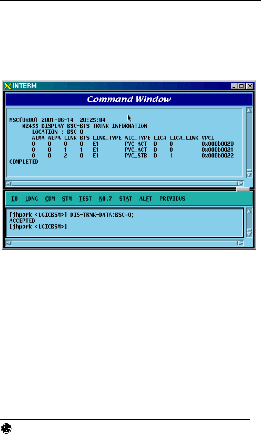
4.3.3.18. BSC-BTS TRUNK Information Display
• Command DIS-TRNK-DATA: BSC=a;
a: BSC Number (0~11)
• Input DIS-TRNK-DATA: BSC=0;
• Output
Fig. 4.3-55 BSC-BTS TRUNK Information Display
STAREX-IS BSM Manual
Page:232(877)
Issue:1.
0
SMD-011-PMA210
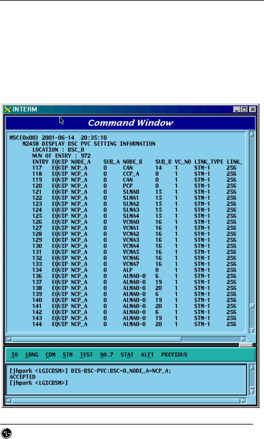
4.3.3.19. BSC PVC SETTING Information Display
• Command DIS-BSC-PVC: BSC=a,NODE_A=b;
a: BSC Number (0~11)
b: NCP_A, NCP_B, CCP_A, CCP_B, ALMA0_0 , ALMA0_1, ALMA1_0 ,
ALMA1_1,CAN,CPN,ALP
• Input DIS-BSC-PVC: BSC=0,NODE_A=NCP_A;
• Output

STAREX-IS BSM Manual
Page:233(877)
Issue:1.
0
SMD-011-PMA210
Fig. 4.3-56 BSC PVC SETTING Information Display
STAREX-IS BSM Manual
Page:234(877)
Issue:1.
0
SMD-011-PMA210
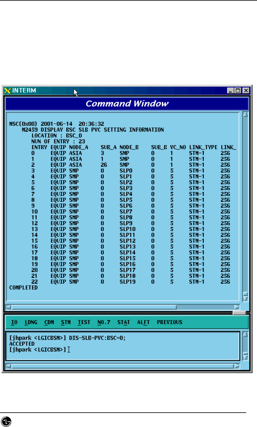
4.3.3.20. BSC SLB PVC SETTING Information Display
• Command DIS-SLB-PVC: BSC=a;
a: BSC Number (0~11)
• Input DIS-SLB-PVC: BSC=0;
• Output
Fig. 4.3-57 BSC SLB PVC SETTING Information Display
STAREX-IS BSM Manual
Page:235(877)
Issue:1.
0
SMD-011-PMA210
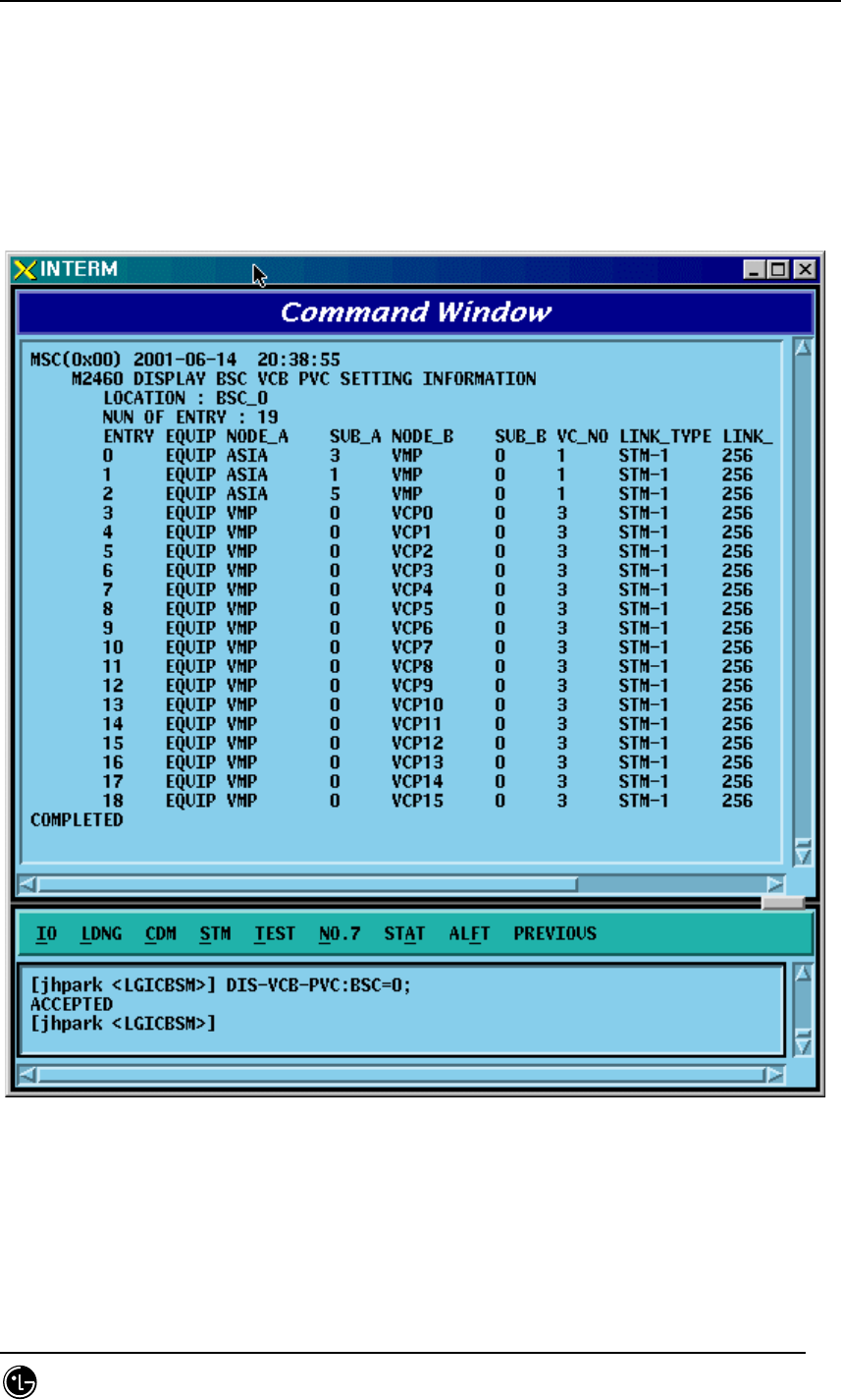
4.3.3.21. BSC VCB PVC SETTING Information Display
• Command DIS-VCB-PVC: BSC=a;
a: BSC Number (0~11)
• Input DIS-VCB-PVC: BSC=0;
• Output
Fig. 4.3-58 BSC VCB PVC SETTING Information Display
STAREX-IS BSM Manual
Page:236(877)
Issue:1.
0
SMD-011-PMA210
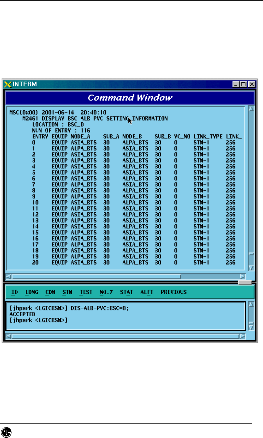
4.3.3.22. BSC ALB PVC SETTING Information Display
• Command DIS-ALB-PVC: BSC=a;
a: BSC Number (0~11)
• Input DIS-ALB-PVC: BSC=0;
• Output
Fig. 4.3-59 BSC ALB PVC SETTING Information Display
STAREX-IS BSM Manual
Page:237(877)
Issue:1.
0
SMD-011-PMA210
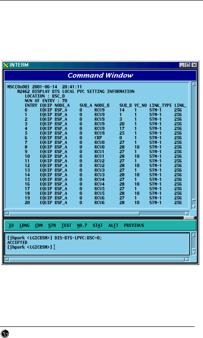
4.3.3.23. BTS LOCAL PVC SETTING Information Display
• Command DIS-BTS-LPVC: BSC=a;
a: BSC Number (0~11)
• Input DIS-BTS-LPVC: BSC=0;
• Output
Fig. 4.3-60 BTS LOCAL PVC SETTING Information Display
STAREX-IS BSM Manual
Page:238(877)
Issue:1.
0
SMD-011-PMA210
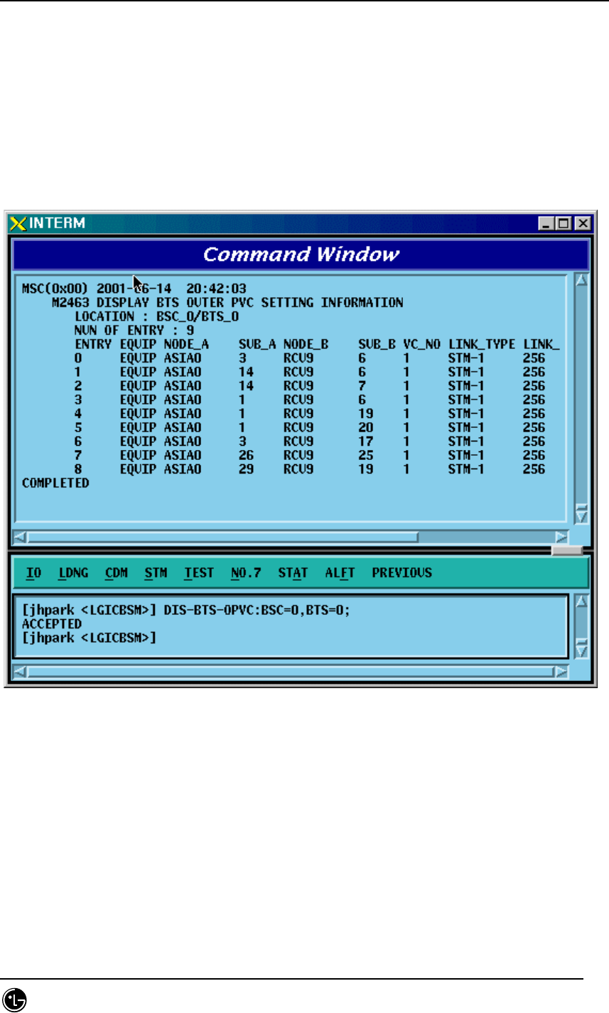
4.3.3.24. BTS OUTER PVC SETTING Information Display
• Command DIS-BTS-OPVC: BSC=a, BTS=b;
a: BSC Number (0~11)
b: BTS Number(0~47)
• Input DIS-BTS-OPVC: BSC=0, BTS=0;
• Output
Fig. 4.3-61 BTS OUTER PVC SETTING Information Display

STAREX-IS BSM Manual
Page:239(877)
Issue:1.
0
SMD-011-PMA210
4.3.3.25. BSC NETWORK PARAMETER Information Display
• Command DIS-BSC-NETP: BSC=a;
a: BSC Number (0~11)
• Input DIS-BSC-NETP: BSC=0;
• Output
Fig. 4.3-62 BSC NETWORK PARAMETER Information Display
STAREX-IS BSM Manual
Page:240(877)
Issue:1.
0
SMD-011-PMA210
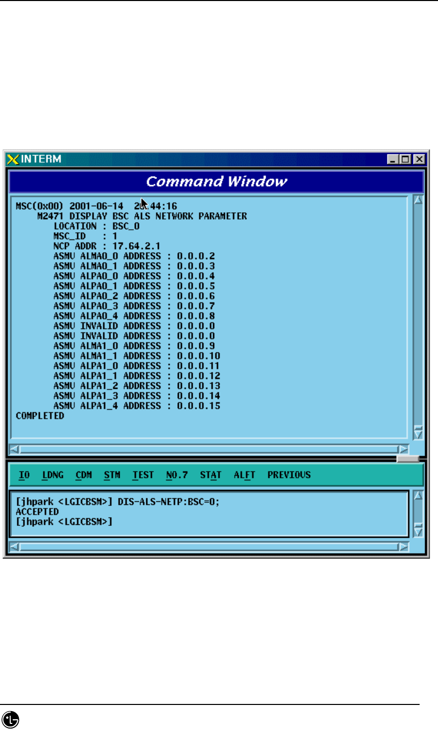
4.3.3.26. BSC ALP NETWORK PARAMETER Information Display
• Command DIS-ALS-NETP: BSC=a;
a: BSC Number (0~11)
• Input DIS-ALS-NETP: BSC=0;
• Output
Fig. 4.3-63 BSC ALP NETWORK PARAMETER Information Display
STAREX-IS BSM Manual
Page:241(877)
Issue:1.
0
SMD-011-PMA210
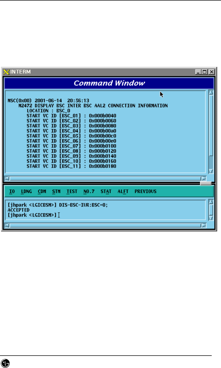
4.3.3.27. BSC INTER BSC AAL2 Information Display
• Command DIS-BSC-IUR: BSC=a;
a: BSC Number (0~11)
• Input DIS-BSC-IUR: BSC=0;
• Output
Fig. 4.3-64 BSC INTER BSC AAL2 Information Display
STAREX-IS BSM Manual
Page:242(877)
Issue:1.
0
SMD-011-PMA210
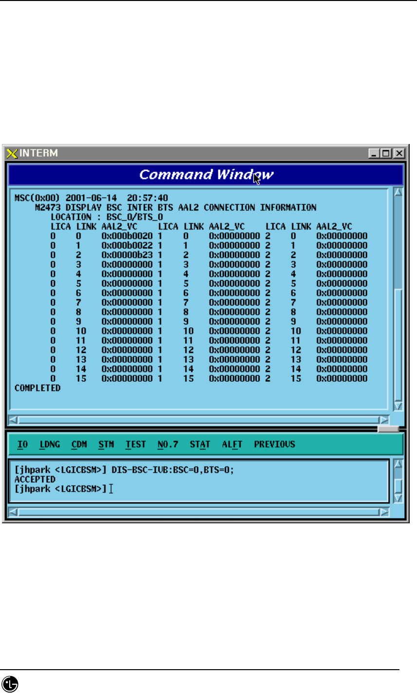
4.3.3.28. BSC INTER BTS AAL2 Information Display
• Command DIS-BSC-IUB: BSC=a, BTS=b;
a: BSC Number (0~11)
b: BTS Number(0~47)
• Input DIS-BSC-IUB: BSC=0, BTS=0;
• Output
Fig. 4.3-65 BSC INTER BTS AAL2 Information Display
STAREX-IS BSM Manual
Page:243(877)
Issue:1.
0
SMD-011-PMA210
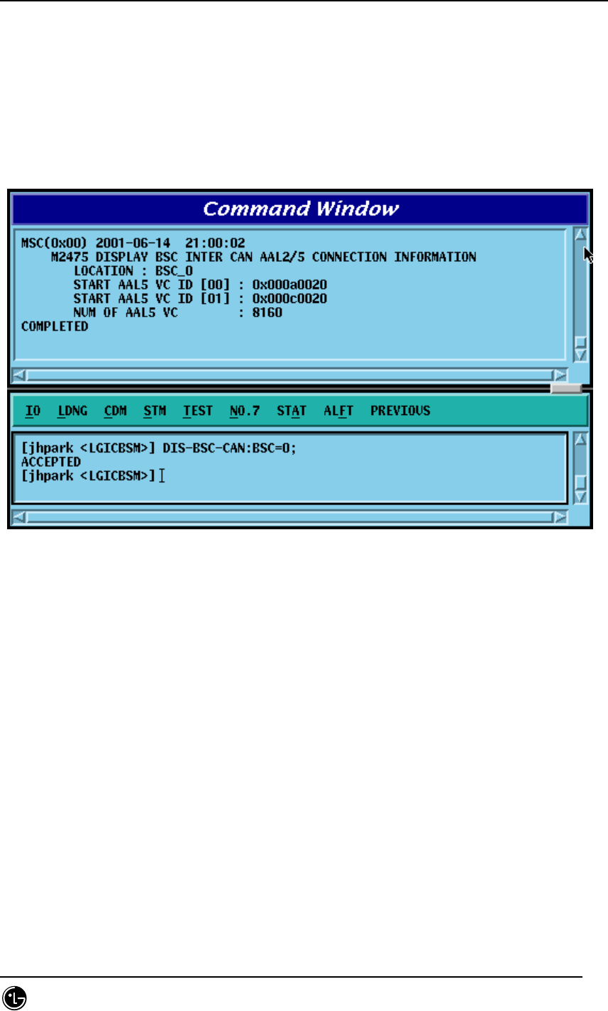
4.3.3.29. BSC INTER CAN AAL2/5 Information Display
• Command DIS-BSC-CAN: BSC=a;
a: BSC Number (0~11)
• Input DIS-BSC-CAN: BSC=0;
• Output
Fig. 4.3-66 BSC INTER CAN AAL2/5 Information Display
STAREX-IS BSM Manual
Page:244(877)
Issue:1.
0
SMD-011-PMA210
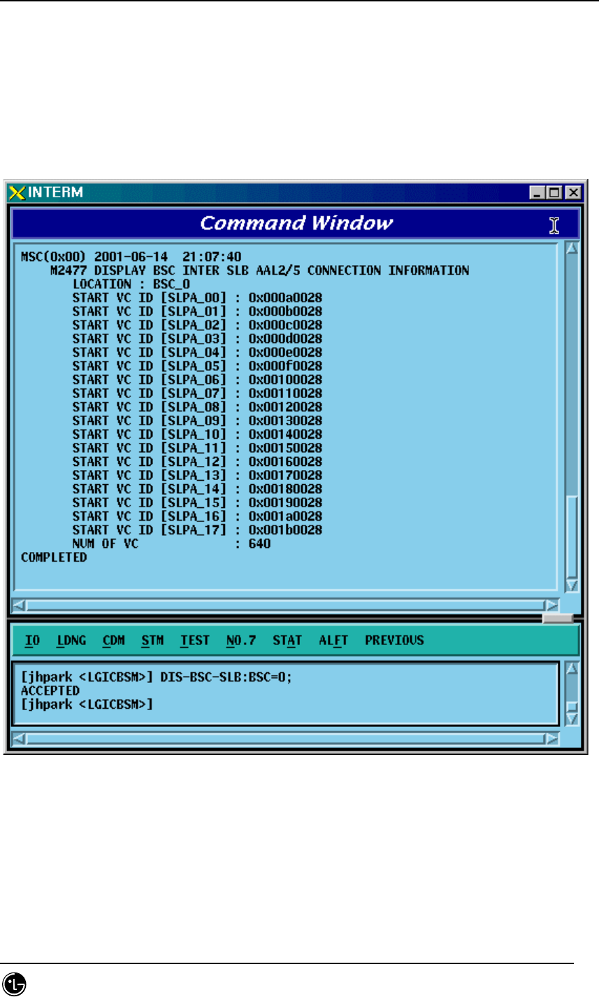
4.3.3.30. BSC INTER SLB AAL5 Information Display
• Command DIS-BSC-SLB: BSC=a;
a: BSC Number (0~11)
• Input DIS-BSC-SLB: BSC=0;
• Output’
Fig. 4.3-67 BSC INTER SLB AAL5 Information Display
STAREX-IS BSM Manual
Page:245(877)
Issue:1.
0
SMD-011-PMA210
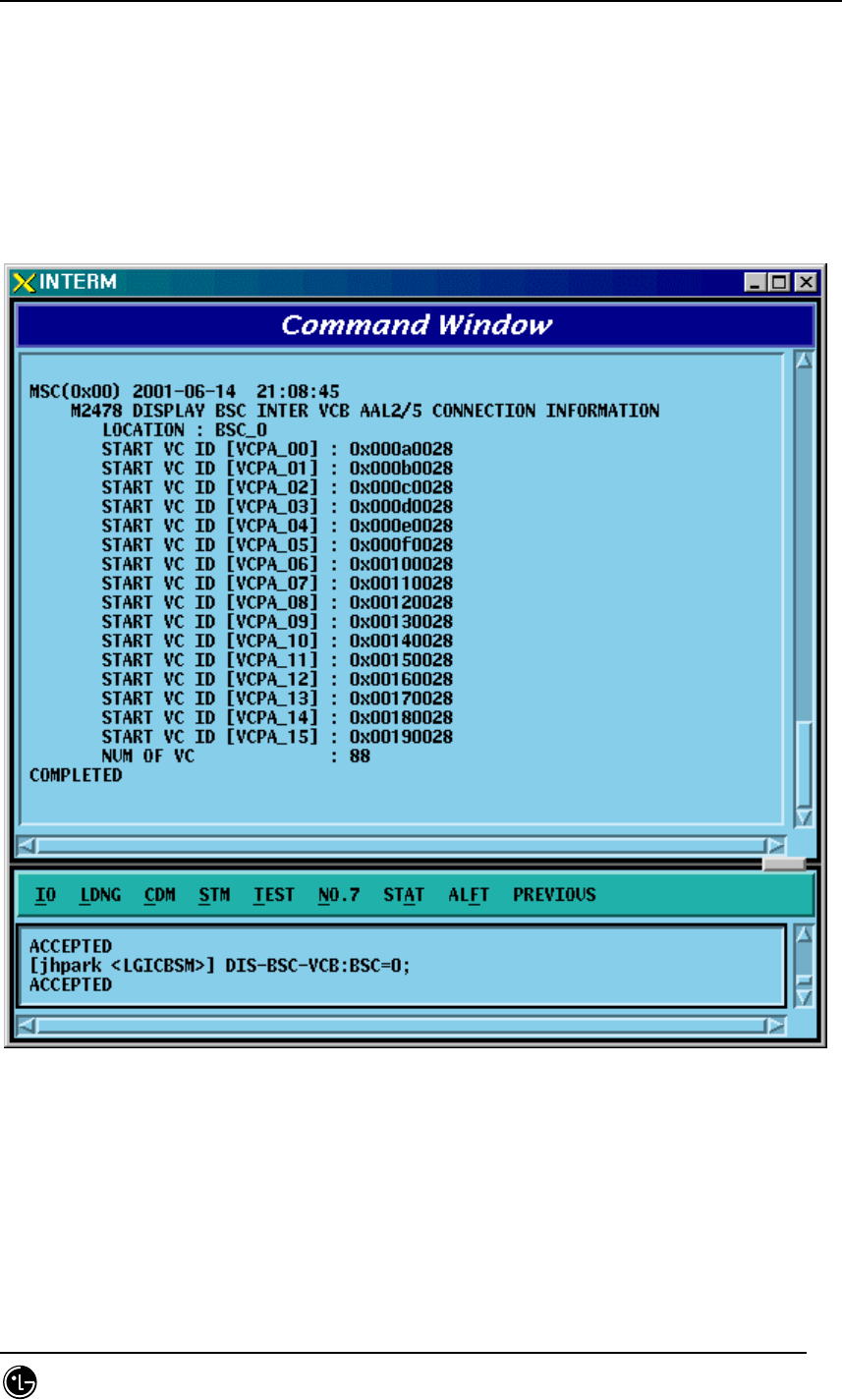
4.3.3.31. BSC INTER VCB AAL5 Information Display
• Command DIS-BSC-VCB: BSC=a;
a: BSC Number (0~11)
• Input DIS-BSC-VCB: BSC=0;
• Output
Fig. 4.3-68 BSC INTER VCB AAL5 Information Display
STAREX-IS BSM Manual
Page:246(877)
Issue:1.
0
SMD-011-PMA210
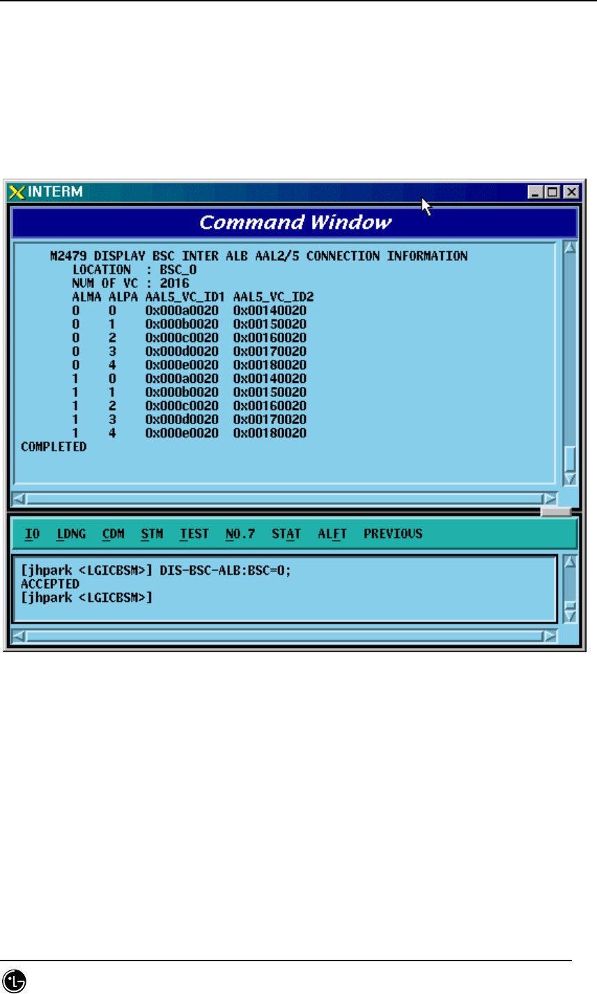
4.3.3.32. BSC INTER ALB AAL5 Information Display
• Command DIS-BSC-ALB: BSC=a;
a: BSC Number (0~11)
• Input DIS-BSC-ALB: BSC=0;
• Output
Fig. 4.3-69 BSC INTER ALB AAL5 Information Display
STAREX-IS BSM Manual
Page:247(877)
Issue:1.
0
SMD-011-PMA210
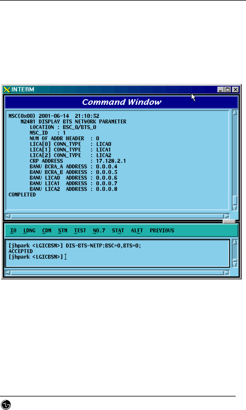
4.3.3.33. BTS NETWORK PARAMETER Information Display
• Command DIS-BTS-NETP: BSC=a ,BTS=b;
a: BSC Number (0~11)
b: BTS Number (0~47)
• Input DIS-BTS-NETP: BSC=0,BTS=0;
• Output
Fig. 4.3-70 BTS NETWORK PARAMETER Information Display
STAREX-IS BSM Manual
Page:248(877)
Issue:1.
0
SMD-011-PMA210
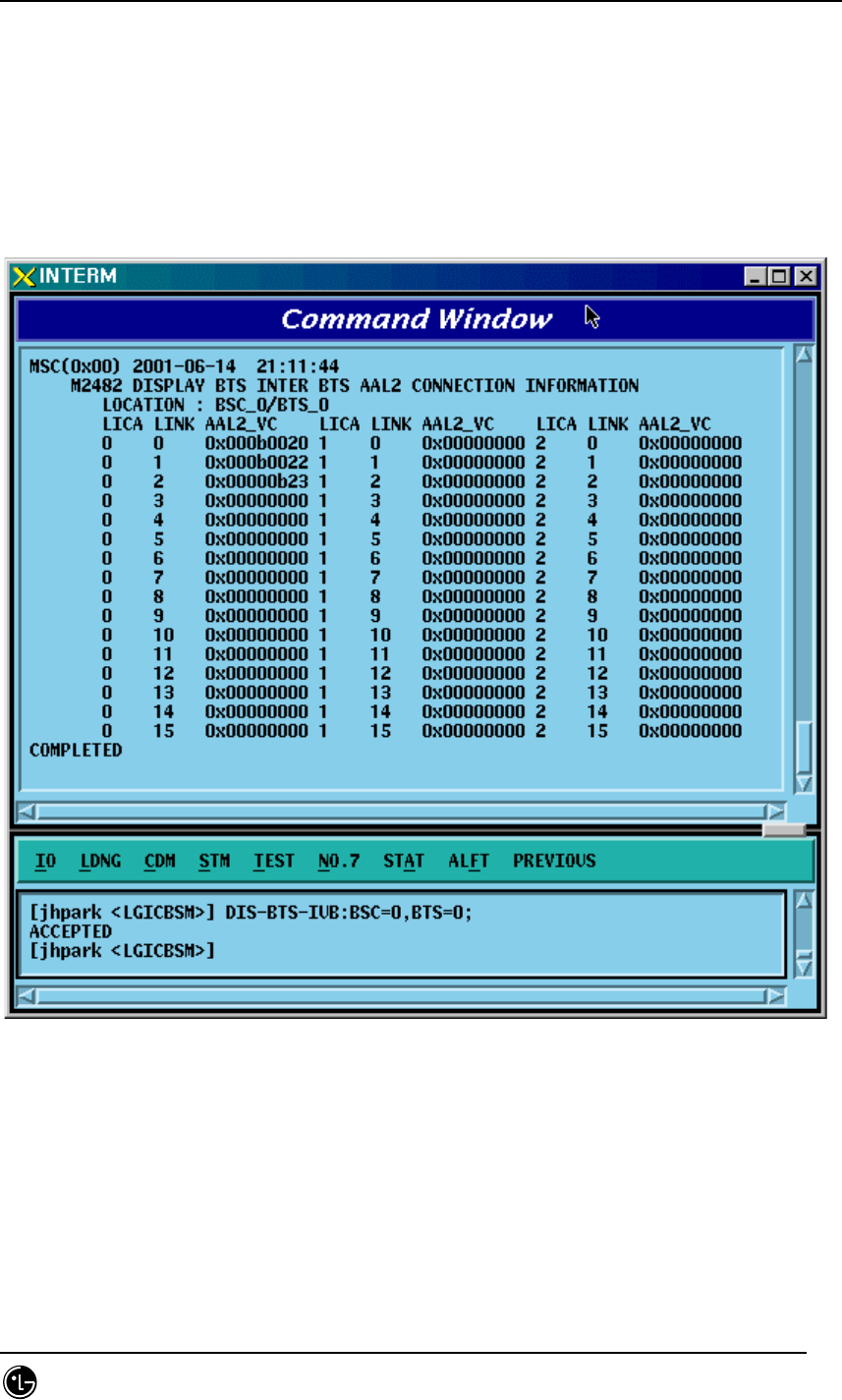
4.3.3.34. BTS INTER BTS AAL2 Information Display
• Command DIS-BTS-IUB: BSC=a ,BTS=b;
a: BSC Number (0~11)
b: BTS Number (0~47)
• Input DIS-BTS-IUB: BSC=0,BTS=0;
• Output
Fig. 4.3-71 BTS INTER BTS AAL2 Information Display
STAREX-IS BSM Manual
Page:249(877)
Issue:1.
0
SMD-011-PMA210
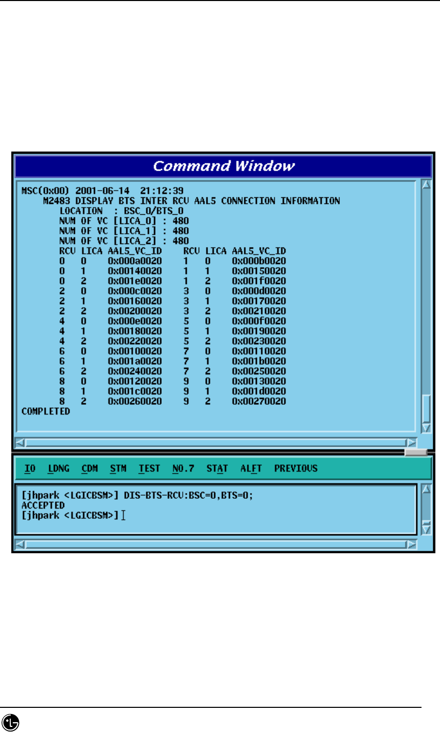
4.3.3.35. BTS INTER RCU AAL5 Information Display
• Command DIS-BTS-RCU: BSC=a ,BTS=b;
a: BSC Number (0~11)
b: BTS Number (0~47)
• Input DIS-BTS-RCU: BSC=0,BTS=0;
• Output
Fig. 4.3-72 BTS INTER RCU AAL5 Information Display

STAREX-IS BSM Manual
Page:250(877)
Issue:1.
0
SMD-011-PMA210
4.3.4. Parameter Information Change Command
(Change_Parameter_Information_1)
This section describes commands that are used to change the parameter information
that is inquired. The command to change parameter information cannot be easily input
by the keyboard since input parameter counts are too many. For this reason, this
section will skip the command input in Text and demonstrate window input by mouse.
Upon inputting the command, the part in blue is the parameter that the user can change
and the user can change part or entire fields among them. For details of each
parameter that is input, refer to Appendix.

STAREX-IS BSM Manual
Page:251(877)
Issue:1.
0
SMD-011-PMA210
Table 4.3-1 Parameter Data Change Command (1) List
2201 CHG-BTS-DATA BTS parameter data change
2202 CHG-SECT-DATA SECTOR Parameter data change
2203 CHG-CHAN-DATA CDMA CHANNEL parameter data Change
2205 CHG-SYS1-PARA SYSTEM PARAMETER(1) change
2206 CHG-SYS2-PARA SYSTEM PARAMETER(2) change
2207 CHG-EXT1-SYS EXTENDED SYSTEM PARAMETER(1) change
2208 CHG-EXT2-SYS EXTENDED SYSTEM PARAMETER(2) change
2209 ADD-NGBR-DATA Addition of Neighbor cell data
2210 RMV-NGBR-DATA Deletion of Neighbor cell data
2211 CHG-NGBR-DATA Neighbor cell data change
2213 CHG-NGBR-BCON HOPPING BEACON PARAMETER change
2214 CHG-QOS-PARA QOS parameter data change
2216 CHG-CHIP-PWR Chip Power Control data change
2222 CHG-TIC-DATA TIC parameter data change
2223 CHG-SECT-CHAN Sector CDMA Channel change
2224 CHG-PWR-PARA Power control parameter data change
2225 CHG-AC-PARA ACCESS CHANNEL parameter information change
2226 CHG-TXMS-PARA TXMS parameter data change
2227 START-BTS-CALB BTS CALIBRATION start
2229 CHG-GSRM-PARA PC GLOBAL REDIRECT parameter change
2230 CHG-ACC-PARA ACCESS PARAMETER change
2232 CHG-PC-PARA PAGING CHANNEL parameter data change
2233 CHG-PICH-PARA PILOT CHANNEL parameter data change
2236 CHG-SC-PARA SYNC CHANNEL parameter data change
2238 CHG-QPC-PARA QUICH PAGING CHANNEL parameter data change
2239 CHG-BCON-PARA HOPPING PILOT BEACON CHANNEL parameter data
change
STAREX-IS BSM Manual
Page:252(877)
Issue:1.
0
SMD-011-PMA210
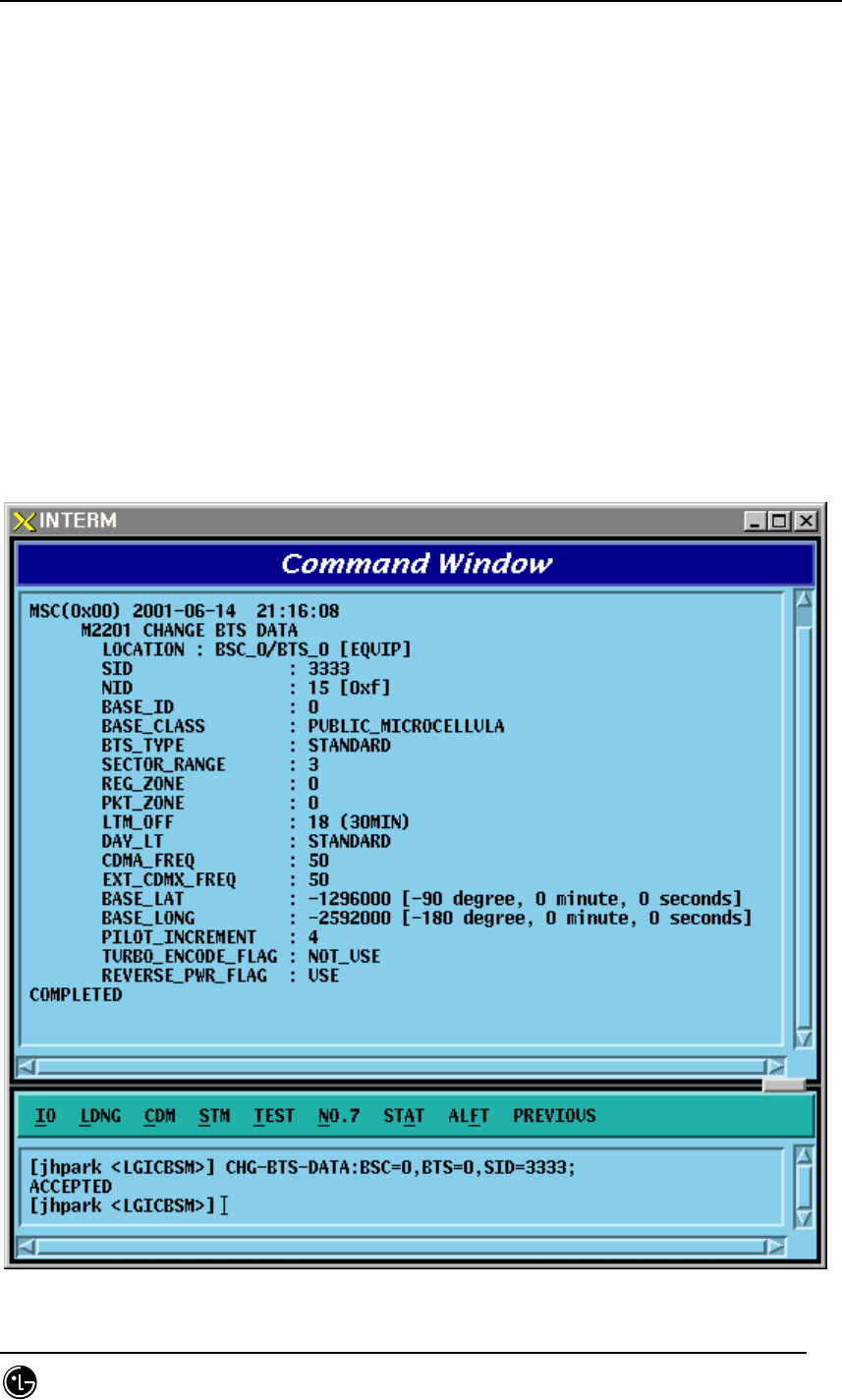
4.3.4.1. BTS Parameter Information Change
To change the BTS parameter information, click CDM->Change_Parameter_
Information->Change BTS Data on the Command Window in order and input the value
that the command wants to change in each field.
• Command CHG-BTS-DATA :BSC=a ,BTS=b [,SID=c] [,NID=d] [,BASE_ID=e]
[,BASE_CLASS=f] [,REG_ZONE=g] [,LTM_OFF=h]
[,DAY_LT=i] [,BASE_LAT=j] [,BASE_LONG=k]
[,TUB_ENC=l] [,REV_PWR=m];
• Input CHG-BTS-DATA :BSC=0 ,BTS=0 ,SID=3333;
• Output
STAREX-IS BSM Manual
Page:253(877)
Issue:1.
0
SMD-011-PMA210
Fig. 4.3-73 BTS Parameter Information Display
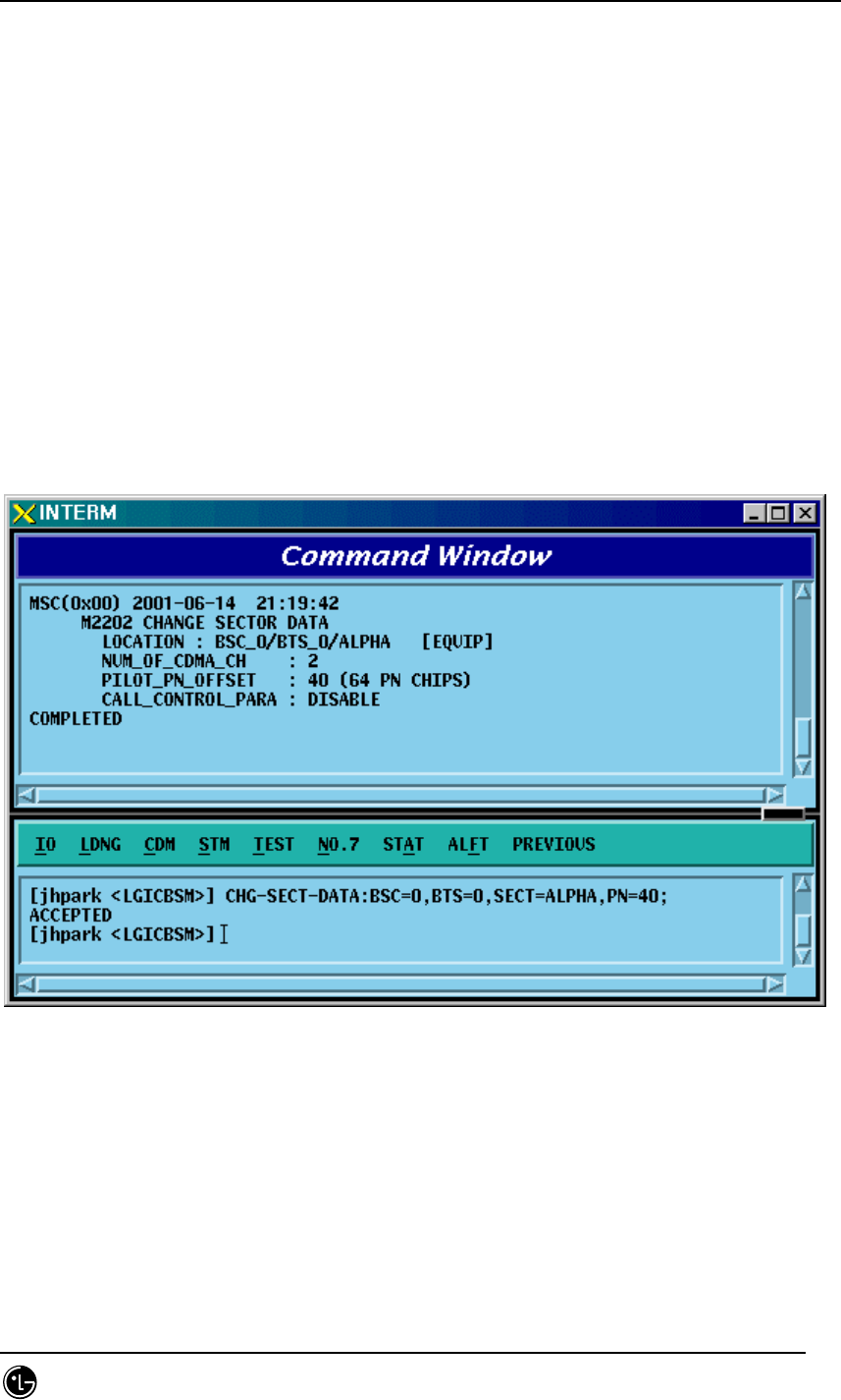
4.3.4.2. Sector Parameter Information Change
To change the sector parameter information, click CDM->Change_Parameter_
Information_1-> CHG-SECT-DATA on the Command Window in order. If the next
input window is displayed, then input the value to be changed.
• Command CHG-SECT-DATA :BSC=a ,BTS=b ,SECT=c [,PN=d]
[,CNTL_PARA=e] ;
• Input CHG-SECT-DATA :BSC=0 ,BTS=0 ,SECT=ALPHA ,PN=40;
• Output
Fig. 4.3-74 Sector Parameter Information Change
STAREX-IS BSM Manual
Page:254(877)
Issue:1.
0
SMD-011-PMA210
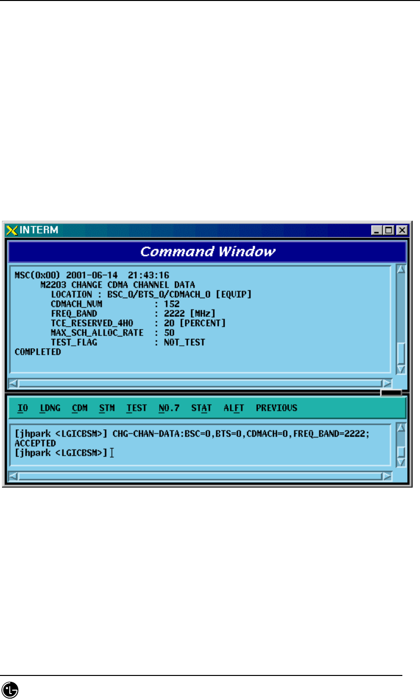
4.3.4.3. CDMA Channel Parameter Information Change
To change the CDMA parameter information, click CDM->Change_Parameter_
Information_1-> CHG-CHAN-DATA on the Command Window in order. If the next
input window is displayed, then input the value to be changed.
• Command CHG-CHAN-DATA :BSC=a ,BTS=b ,CDMACH=c
[,FREQ_BAND=d] [,CH_NUM=e] [,TCE_4HO=f] [,MAX_SCH=g];
• Input CHG-CHAN-DATA :BSC=0,BTS=0 ,CDMACH=0 ,FREQ_BAND=2222;
• Output
Fig. 4.3-75 CDMA Channel Parameter Information Display
STAREX-IS BSM Manual
Page:255(877)
Issue:1.
0
SMD-011-PMA210
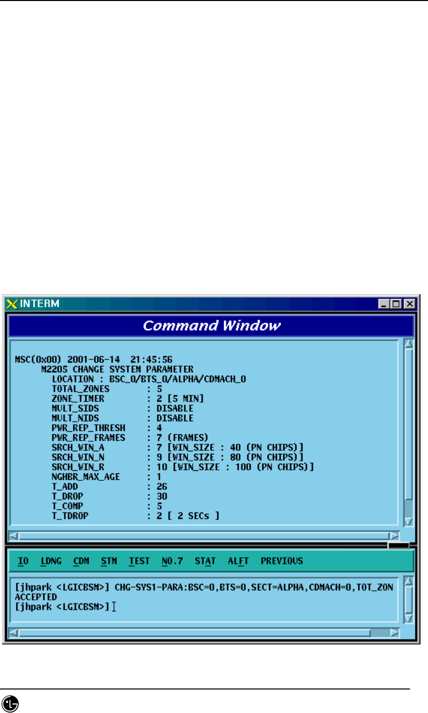
4.3.4.4. SYSTEM PARAMETER(1) Change
To change the system parameter message, click CDM->
Change_Parameter_Information_1-> CHG-SYS1-PARA on the Command Window in
order. As the System Parameter Message have many elements, they are divided into
the three commands. The output format for each command is the same.
• Command CHG-SYS1-PARA :BSC=a ,BTS=b ,SECT=c ,CDMACH=d [,TOT_ZONE=e]
[,ZONE_TIME=f] [,MULT_SIDS=g] [,MULT_NIDS=h]
[,REP_THSH=i] [,REP_FRAM=j] [,SRCH_WINA=k]
[,SRCH_WINN=l] [,SRCH_WINR=m] [,NGHB_MAGE=n] [,T_ADD=o]
[,T_DROP=p] [,T_COMP=q] [,T_TDRP=r];
• Input CHG-SYS1-PARA :BSC=0,BTS=0 ,SECT=ALPHA,CDMACH=0,TOT_ZONE=5
• Output

STAREX-IS BSM Manual
Page:256(877)
Issue:1.
0
SMD-011-PMA210
Fig. 4.3-76 System Parameter Change(1) Display
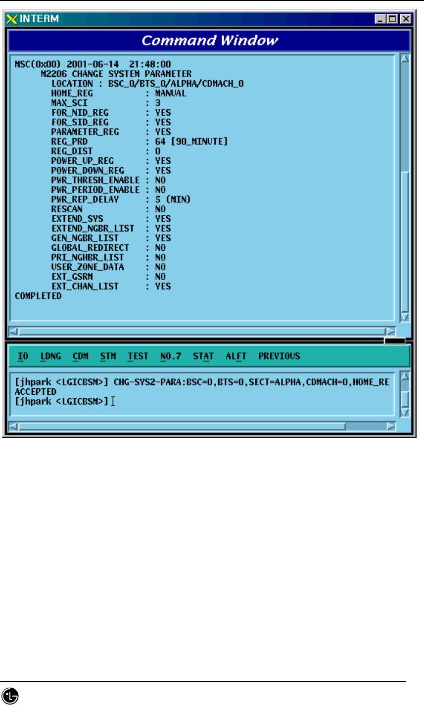
4.3.4.5. SYSTEM
4.3.4.6. PARAMETER(2) Change
To change the system parameter message, click CDM->
Change_Parameter_Information_1-> CHG-SYS2-PARA on the Command Window in
order. Since the System Parameter Message have many elements, they are divided
into three commands. The output format for each command is the same.
• Input CHG-SYS2-PARA :BSC=a ,BTS=b ,SECT=c ,CDMACH=d [,HOME_REG=e]
[,MAX_SCI=f] [,NID_REG=g] [,SID_REG=h] [,PARM_REG=i] [,REG_PRD=j]
[,REG_DIST=k] [,PWR_UP=l] [,PWR_DOWN=m]
[,THSH_EABL=n] [,PRID_EABL=o] [,REP_DELY=p]
[,RE_SCAN=q] [,EXT_SYS=r] [,EXT_NGHBR=s] [,GEN_NGHBR=t]
[,REDIRECT=u] [,PRI_NGHBR=v] [,USER_ZONE=w]
[,EXT_REDIRECT=x] [,EXT_CHAN=y] ;
• Output CHG-SYS2-PARA :BSC=0 ,BTS=0,SECT=ALPHA ,CDMACH=0,
HOME_REG=MANUAL;
• Display
STAREX-IS BSM Manual
Page:257(877)
Issue:1.
0
SMD-011-PMA210
Fig. 4.3-77 System Parameter Change(2) Display

STAREX-IS BSM Manual
Page:258(877)
Issue:1.
0
SMD-011-PMA210
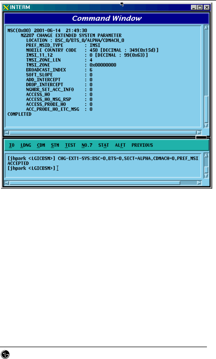
4.3.4.7. EXTENDED SYSTEM PARAMETER(1) Change
To change the Extended System Parameter Message, click CDM->
Change_Parameter_Information_1-> CHG-EXT1-SYS on the Command Window in
order. If the next input window is displayed, then input the value to be changed.
• Change CHG-EXT1-SYS :BSC=a ,BTS=b ,SECT=c ,CDMACH=d [,PREF_MSID=e]
[,MCC=f] [,IMSI_11_12=g] [,TMSI_LEN=h]
[,TMSI_ZONE_1=i] [,TMSI_ZONE_2=j] [,TMSI_ZONE_3=k]
[,TMSI_ZONE_4=l] [,TMSI_ZONE_5=m]
[,TMSI_ZONE_6=n] [,TMSI_ZONE_7=o]
[,TMSI_ZONE_8=p] [,BCAST_IDX=q] [,SOFT_SLOPE=r]
[,ADD_INT=s] [,DROP_INT=t] [,NGBR_SET=u]
[,ACCESS_HO=v] [,HO_MSG_RSP=w] [,ACC_PRB_HO=x] [,PRB_HO_OT=y] ;
• Input CHG-EXT1-SYS :BSC=0 ,BTS=0 ,SECT=ALPHA ,CDMACH=0 ,
PREF_MSID=IMSI;
• Output
STAREX-IS BSM Manual
Page:259(877)
Issue:1.
0
SMD-011-PMA210
Fig. 4.3-78 Extended System Parameter Change(1) Display

STAREX-IS BSM Manual
Page:260(877)
Issue:1.
0
SMD-011-PMA210
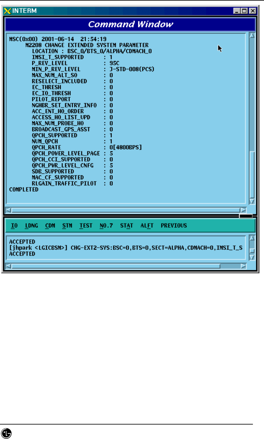
4.3.4.8. EXTENDED SYSTEM PARAMETER(2) Change
To change the Extended System Parameter Message, click CDM->
Change_Parameter_Information_1-> CHG-EXT2-SYS on the Command Window in
order. If the next input window is displayed, then input the value to be changed.
• Command CHG-EXT2-SYS :BSC=a ,BTS=b ,SECT=c ,CDMACH=d
[,IMSI_T_SUPRT=e]
[,P_REV=f] [,MIN_P_REV=g] [,MAX_ALT_SO=h]
[,RESEL_INCL=i] [,EC_THRESH=j]
[,EC_IO_THRESH=k] [,PILOT_REPORT=l]
[,NGBR_SET_INF=m] [,ACC_HO_ORD=n] [,HO_LIST_UPD=o]
[,MAX_PRB_HO=p] [,BRD_GPS_ASS=q] [,QPC_SUPPORT=r] [,NUM_QPCH=s]
[,QPCH_RATE=t] [,QPC_PWR_LEV=u] [,QPC_CCI=v] [,QPC_PWR_CFG=w]
[,SDB_SUPPORT=x] [,MAC_CF_SPRT=y] [,RLGAIN_PICH=z];
• Input CHG-EXT2-SYS :BSC=0 ,BTS=0,SECT=ALPHA ,CDMACH=,IMSI_T_SUPRT=1;
• Output
STAREX-IS BSM Manual
Page:261(877)
Issue:1.
0
SMD-011-PMA210
Fig. 4.3-79 Extended System Parameter Change(2) Display
STAREX-IS BSM Manual
Page:262(877)
Issue:1.
0
SMD-011-PMA210
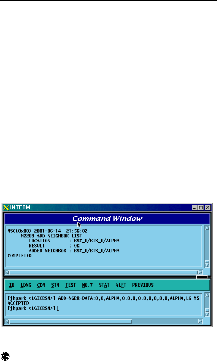
4.3.4.9. Neighbor Cell Information Addition
To add the neighbor list, click the CDM->Change_Parameter_Information_1-> ADD-
NGBR-DATA on the Command Window in order. If the next input window is displayed,
then input the values to be changed.
• Command ADD-NGBR-DATA :BSC=a ,BTS=b ,SECT=c ,INDEX=d ,NGBR_CNFG=e
,NGBR_PN=f ,NGBR_SID=g ,NGBR_NID=h ,NGBR_BASE=i ,NGBR_MSC=j
,NGBR_BSC=k ,NGBR_BTS=l ,NGBR_SECT=m ,NGBR_MSC_T=n
,NGBR_BSC_T=o,NGBR_BCON=p ,SRCH_PRIO=q
,FREQ_INCL=r [,NGBR_BAND=s] [,NGBR_FREQ=t]
[,TIME_INCL=u] [,TX_OFFSET=v] [,TX_DURATION=w] [,TX_PERIOD=x]
[,SRCH_SET=y] [,ADD_PICH_REC=z] [,PICH_REC=] [,OTD_PWR=]
[,SRCH_OFFSET=] [,ACC_HO=] [,ACC_HO_ALW=];
• Input ADD-NGBR-DATA :BSC=0 ,BTS=0 ,SECT=ALPHA ,INDEX=0 ,NGBR_CNFG=0
,NGBR_PN=0 ,NGBR_SID=0 ,NGBR_NID=0 ,NGBR_BASE=0 ,NGBR_MSC=0
,NGBR_BSC=0 ,NGBR_BTS=0 ,NGBR_SECT=ALPHA ,NGBR_MSC_T=LG_MSC
,NGBR_BSC_T=LG_BSC,NGBR_BCON=NO ,SRCH_PRIO=LOW
,FREQ_INCL=NO,NGBR_BAND=Mhz_800;
• Output
STAREX-IS BSM Manual
Page:263(877)
Issue:1.
0
SMD-011-PMA210
Fig. 4.3-80 Neighbor Cell Addition Display
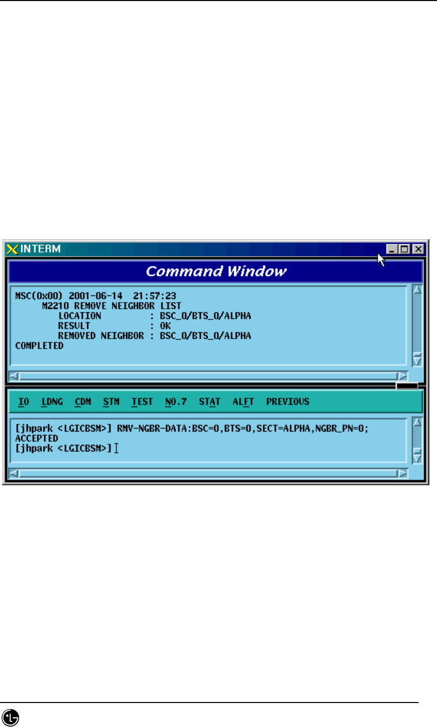
4.3.4.10. Neighbor Cell Information Deletion
To delete the neighbor list, click CDM->Change_Parameter_Information_1-> RMV-
NGBR-DATA on the Command Window in order. If the next window is displayed, then
input the sector and PN value of the sector to be deleted.
• Command RMV-NGBR-DATA :BSC=a ,BTS=b ,SECT=c ,NGBR_PN=d;
• Input RMV-NGBR-DATA :BSC=0 ,BTS=0 ,SECT=ALPHA ,NGBR_PN=0;
• Output
Fig. 4.3-81 Neighbor Cell Information Deletion Display

STAREX-IS BSM Manual
Page:264(877)
Issue:1.
0
SMD-011-PMA210
4.3.4.11. Neighbor Cell Information Change
To change the neighbor list, click CDM->Change_Parameter_Information_1-> CHG-
NGBR-DATA on the Command Window in order. If the next input Window is displayed,
input the sector and the PN value of the sector to be deleted.
• Command CHG-NGBR-
DATA :BSC=a ,BTS=b ,SECT=c ,NGBR_PN=d ,NEW_INDEX=e
• Input
• Output
STAREX-IS BSM Manual
Page:265(877)
Issue:1.
0
SMD-011-PMA210
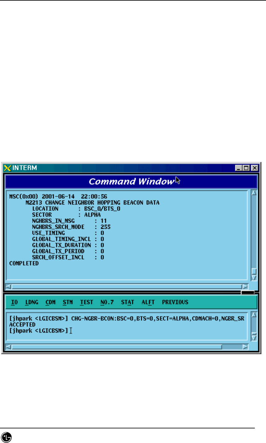
4.3.4.12. HOPPING BEACON PARAMETER Change
To change Hopping Beacon Parameter, click CDM->Change_Parameter_Information_1-
> CHG-NGBR-BCON on the Command Window in order.
• Command CHG-NGBR-BCON :BSC=a ,BTS=b ,SECT=c ,CDMACH=d
[,NGBR_SRCH=e]
[,USE_TIMING=f] [,G_TIME_INCL=g] [,G_TX_DURATE=h]
[,G_TX_PERIOD=i] [,SRCH_OFF_INC=j] ;
• Input CHG-NGBR-BCON :BSC=0 ,BTS=0 ,SECT=ALPHA ,CDMACH=0 ,
NGBR_SRCH=255;
• Output
Fig. 4.3-82 Hopping Beacon Parameter Change Display
STAREX-IS BSM Manual
Page:266(877)
Issue:1.
0
SMD-011-PMA210
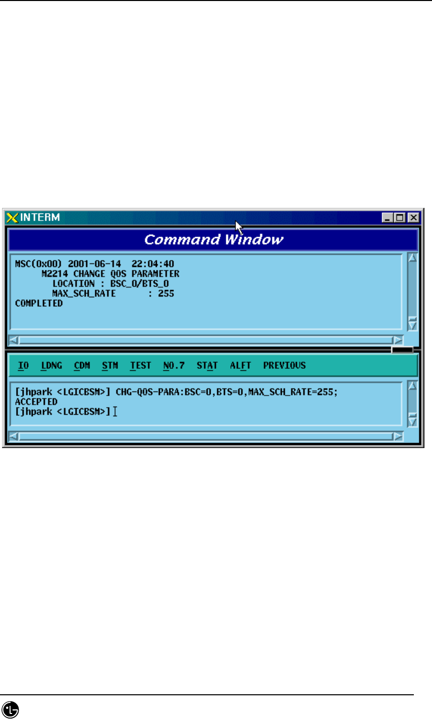
4.3.4.13. QOS Parameter Change
To change Quality Of Service parameter information, click CDM-
>Change_Parameter_Information_1-> CHG-QOS-PARA on the Command Window in
order.
• Command CHG-QOS-PARA :BSC=a ,BTS=b [,MAX_SCH_RATE=c];
• Input CHG-QOS-PARA :BSC=0 ,BTS=0,MAX_SCH_RATE=255;
• Output
Fig. 4.3-83 QOS Parameter Information Change Display

STAREX-IS BSM Manual
Page:267(877)
Issue:1.
0
SMD-011-PMA210
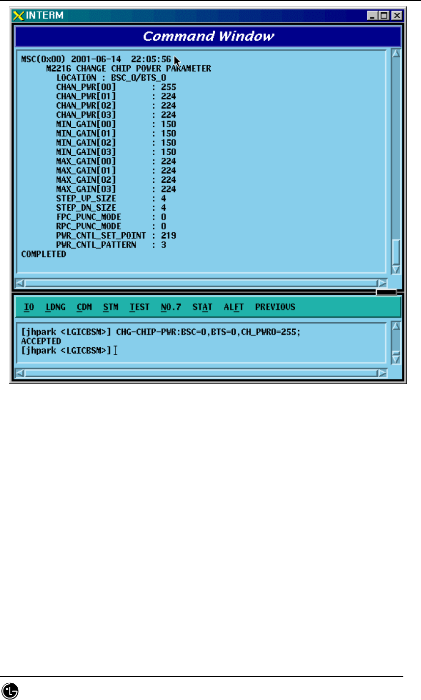
4.3.4.14. Chip Power Control Information Change
To change Chip Power Control information, click CDM-
>Change_Parameter_Information_1-> CHG-CHIP-PWR on the Command Window in
order.
• Command CHG-CHIP-PWR :BSC=a ,BTS=b [,CH_PWR0=c] [,CH_PWR1=d]
[,CH_PWR2=e]
[,CH_PWR3=f] [,MIN_GAIN0=g] [,MIN_GAIN1=h] [,MIN_GAIN2=i]
[,MIN_GAIN3=j][,MAX_GAIN0=k] [,MAX_GAIN1=l] [,MAX_GAIN2=m]
[,MAX_GAIN3=n] [,STEP_UP_SIZE=o] [,STEP_DN_SIZE=p]
[,FPC_PUNC=q] [,RPC_PUNC=r] [,PWR_CNT_PNT=s] [,PWR_CNT_PTN=t] ;
• Input CHG-CHIP-PWR :BSC=0 ,BTS=0 ,CH_PWR0=255;
• Output
STAREX-IS BSM Manual
Page:268(877)
Issue:1.
0
SMD-011-PMA210
Fig. 4.3-84 Chip Power Control Information Change Display
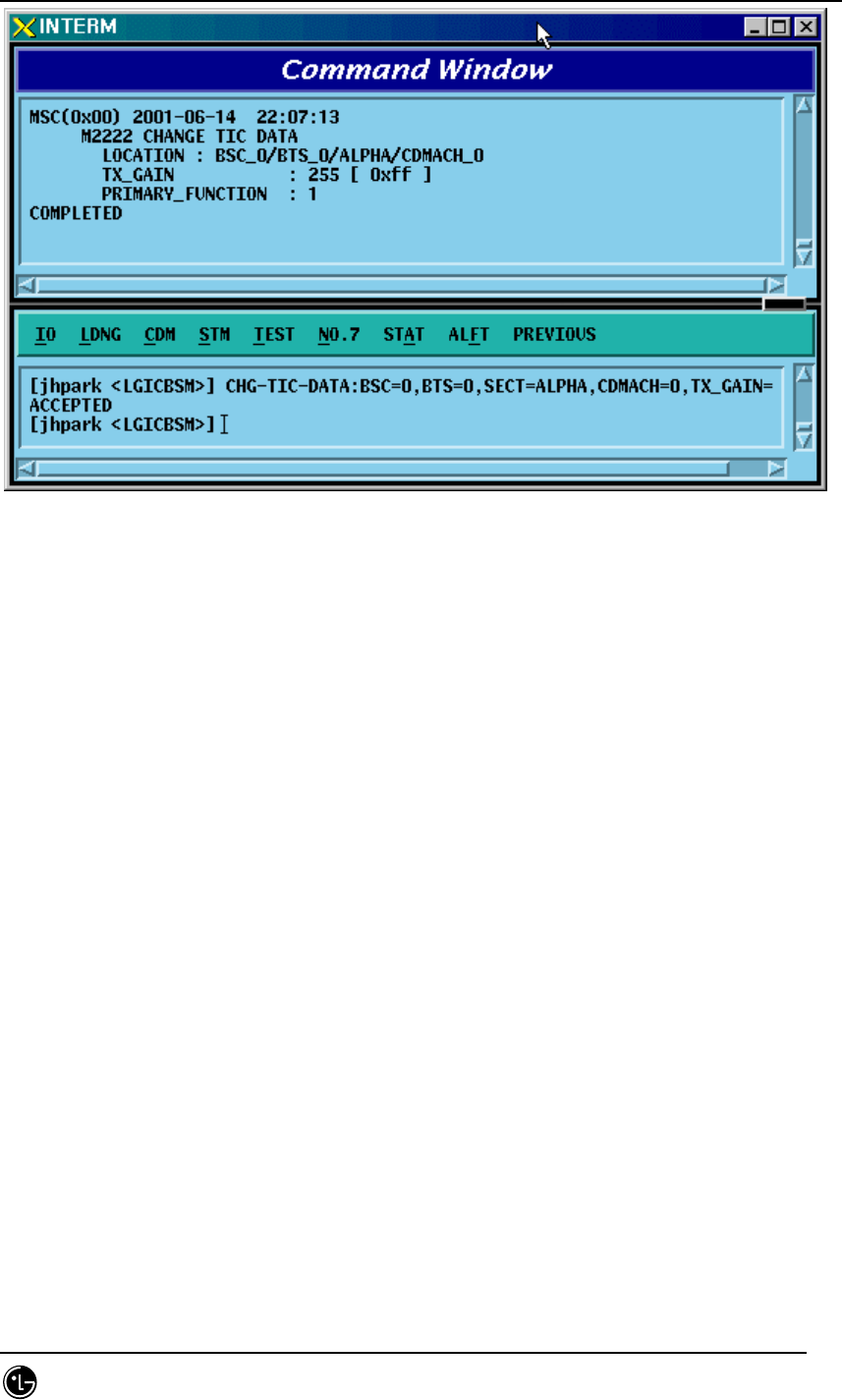
4.3.4.15. TIC Parameter Change
To change Tx Gain value, click CDM->Change_ Parameter_Information_1-> CHG-
TIC-DATA on the Command Window in order. If the next input window is displayed,
then input the value to be changed.
• Command CHG-TIC-DATA :BSC=a ,BTS=b ,SECT=c ,CDMACH=d [,TX_GAIN=e] ;
• Input CHG-TIC-DATA :BSC=0 ,BTS=0 ,SECT=ALPHA ,CDMACH=0 ,TX_GAIN=255 ;
• Output
STAREX-IS BSM Manual
Page:269(877)
Issue:1.
0
SMD-011-PMA210
Fig. 4.3-85 TIC Parameter Information Change Display
STAREX-IS BSM Manual
Page:270(877)
Issue:1.
0
SMD-011-PMA210
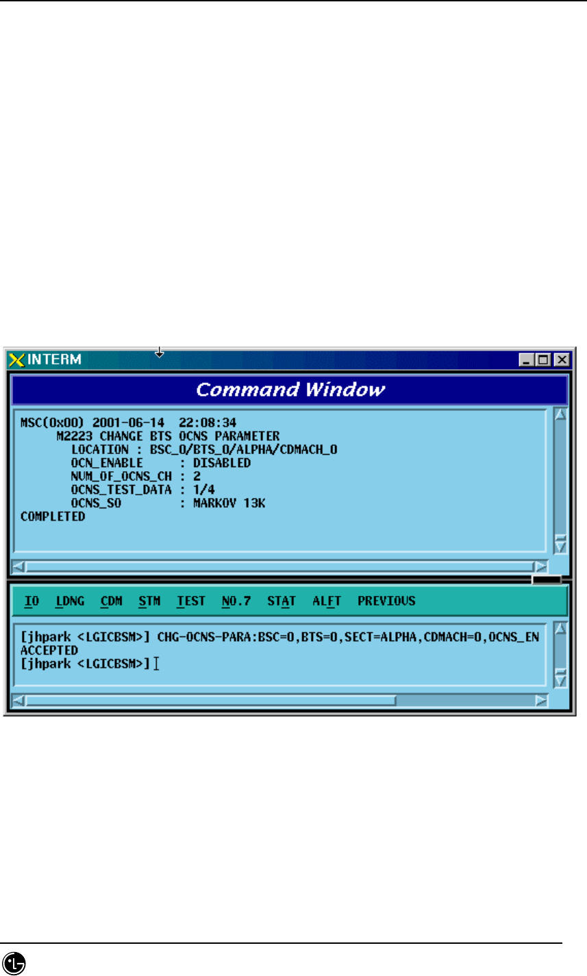
4.3.4.16. OCNS Parameter Change
To change OCNS Parameter value, click CDM->Change_ Parameter_Information_1->
CHG-OCNS-PARA on the Command Window in order. If the next input Window is
displayed, then input the value to be changed.
• Command CHG-OCNS-PARA :BSC=a ,BTS=b ,SECT=c ,CDMACH=d
[,OCNS_ENABLE=e]
[,NUM_OCNS_CH=f] [,OCNS_TEST=g] [,OCNS_SO=h];
• Input CHG-OCNS-PARA :BSC=0 ,BTS=0 ,SECT=ALPHA ,
CDMACH=0 ,OCNS_ENABLE=DISABLE,NUM_OCNS_CH=2;
• Output
Fig. 4.3-86 OCNS Parameter Change Display

STAREX-IS BSM Manual
Page:271(877)
Issue:1.
0
SMD-011-PMA210
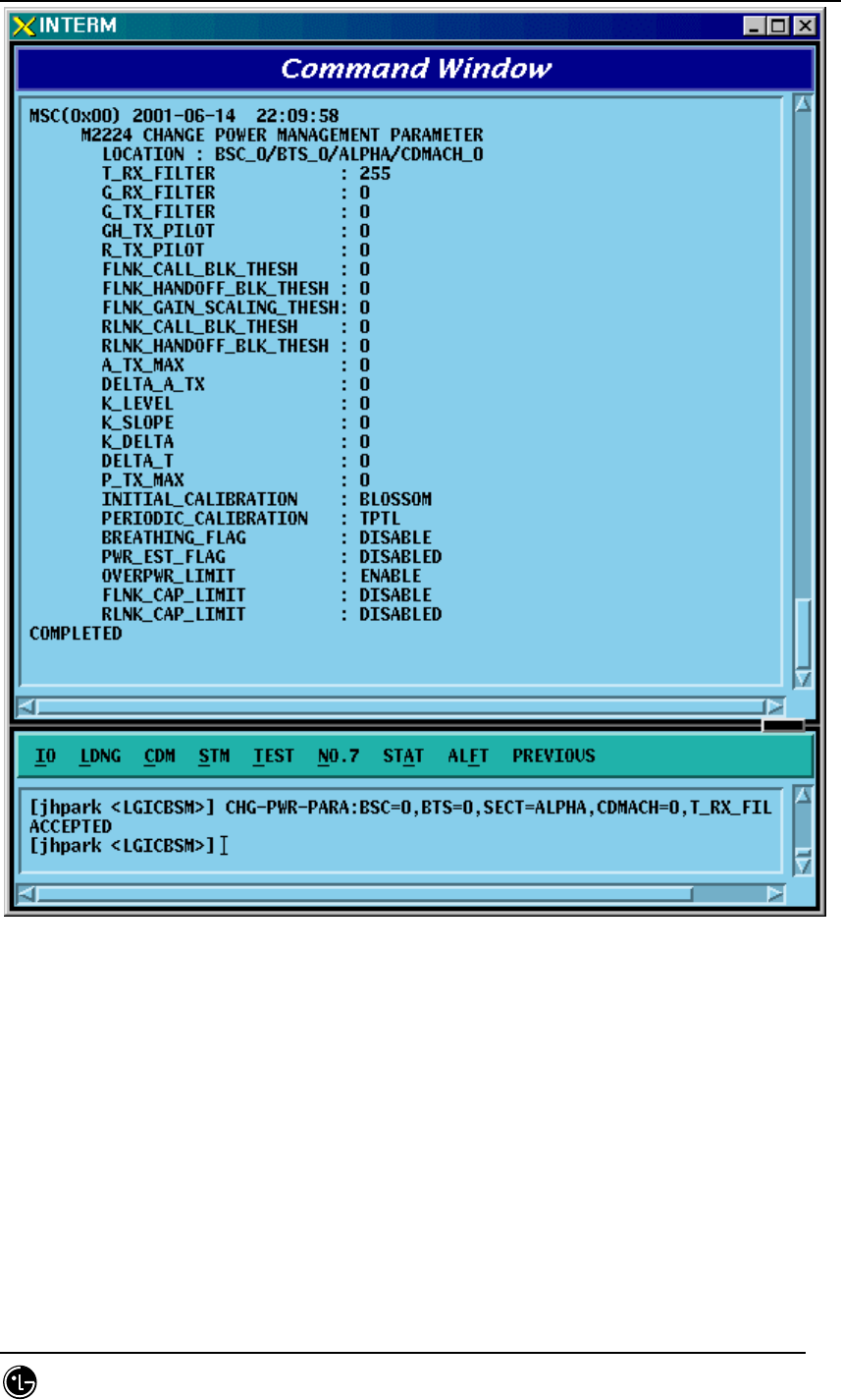
4.3.4.17. Power Control Information Change
To change OCNS Parameter value, click CDM->Change_ Parameter_Information_1->
CHG-PWR-PARA on the Command Window in order. If the next input Window is
displayed, then input the value to be changed.
• Command CHG-PWR-PARA :BSC=a ,BTS=b ,SECT=c ,CDMACH=d
[,T_RX_FILTER=e]
[,G_RX_FILTER=f] [,G_TX_FILTER=g] [,GH_TX_FILTER=h]
[,R_TX_PILOT=i] [,FLN_BLK_THSH=j] [,FLN_HO_THSH=k]
[,FLN_GAIN_SCA=l] [,RLN_BLK_THSH=m] [,RLNK_HO_THSH=n]
[,A_TX_MAX=o] [,DELTA_A_TX=p] [,K_LEVEL=q] [,K_SLOPE=r]
[,K_DELTA=s] [,DELTA_T=t] [,P_TX_MAX=u] [,INIT_CALB=v]
[,PRD_CALIB=w] [,BREATH_FLAG=x] [,PWR_EST_FLAG=y]
[,OVPWR_LMT=z] [,FLN_CAP_LMT=] [,RLN_CAP_LMT=];
• Input CHG-PWR-PARA :BSC=0 ,BTS=0 ,SECT=ALPHA ,CDMACH=0,
T_RX_FILTER=255;
• Output
STAREX-IS BSM Manual
Page:272(877)
Issue:1.
0
SMD-011-PMA210
Fig. 4.3-87 Power Control Parameter Information Display
STAREX-IS BSM Manual
Page:273(877)
Issue:1.
0
SMD-011-PMA210
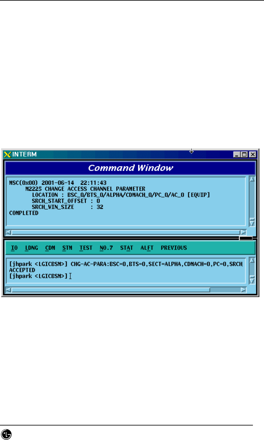
4.3.4.18. ACCESS CHANNEL Parameter Information Change
To change Access Channel Parameter information, click CDM-> Change_
Parameter_Information->CHG-AC-PARA on the Command Window in order. If the
next input window is displayed, then input the value to be changed.
• Command CHG-AC-PARA :BSC=a ,BTS=b ,SECT=c ,CDMACH=d ,PC=e
,AC=f [,SRCH_OFFSET=g] [,SRCH_WIN_SZ=h];
• Input CHG-AC-PARA :BSC=0 ,BTS=0 ,SECT=ALPHA ,
CDMACH=0 , PC=0, SRCH_WIN_SZ=32;
• Output
Fig. 4.3-88 Access Channel Parameter Information Change Display
STAREX-IS BSM Manual
Page:274(877)
Issue:1.
0
SMD-011-PMA210
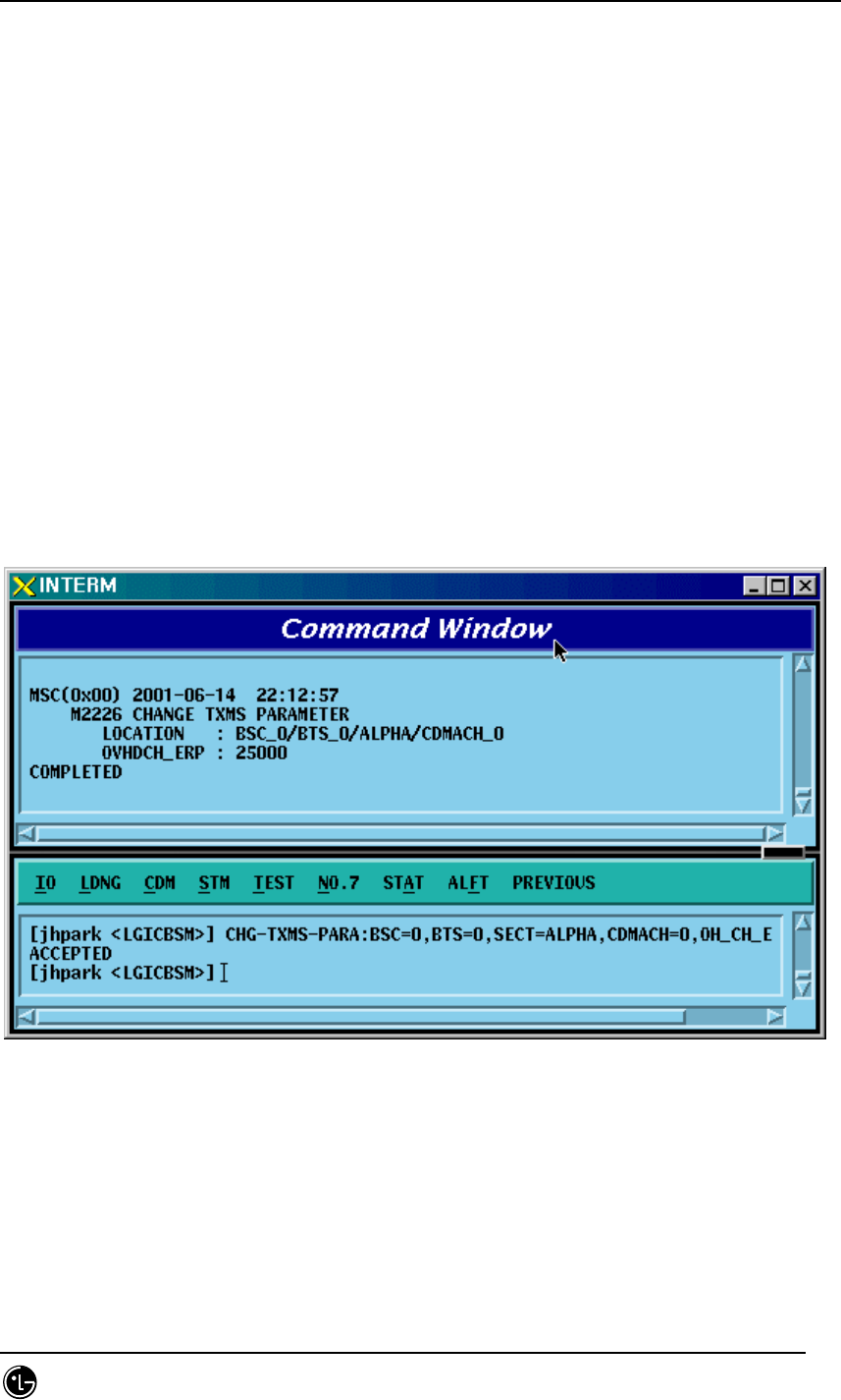
4.3.4.19. TXMS Parameter Information Change
To change TXMS Parameter information, click CDM-> Change_
Parameter_Information->CHG-TXMS-PARA on the Command Window in order. If the
next input window is displayed, then input the value to be changed.
•Command CHG-TXMS-
PARA :BSC=a ,BTS=b ,SECT=c ,CDMACH=d ,OH_CH_ERP=e ;
• Input CHG-TXMS-PARA :BSC=0 ,BTS=0 ,SECT=ALPHA ,CDMACH=0 ,
OH_CH_ERP=25000 ;
• Output
Fig. 4.3-89 TXMS Parameter Information Change Display
STAREX-IS BSM Manual
Page:275(877)
Issue:1.
0
SMD-011-PMA210
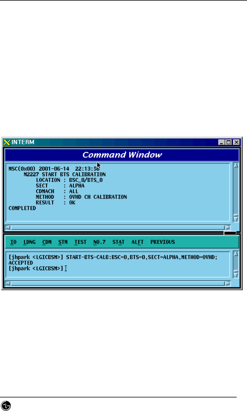
4.3.4.20. BTS CALIBRATION Start
To start BTS Calibration, click CDM-> Change_ Parameter_Information->START-
BTS-CALB on the Command Window in order. If the next input window is displayed,
then input the value to be changed.
• Command START-BTS-CALB :BSC=a ,BTS=b [,SECT=c]
[,CDMACH=d] ,METHOD=e ;
• Input START-BTS-CALB :BSC=0 ,BTS=0 ,SECT=ALPHA,METHOD=OVHD ;
• Output
Fig. 4.3-90 BTS Calibration Start Display
STAREX-IS BSM Manual
Page:276(877)
Issue:1.
0
SMD-011-PMA210
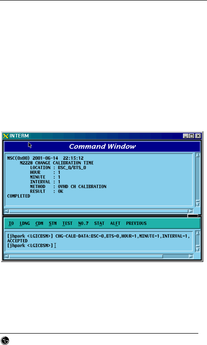
4.3.4.21. BTS Calibration Time Change
To change BTS Calibration time, click CDM-> Change_ Parameter_Information->CHG-
CALB-TIME on the Command Window in order. If the next input window is displayed,
then input the value to be changed.
• Command CHG-CALB-DATA :BSC=a ,BTS=b ,HOUR=c ,MINUTE=d ,INTERVAL=e
,METHOD=f;
• Input CHG-CALB-DATA :BSC=0 ,BTS=0 ,HOUR=1 ,MINUTE=1 ,INTERVAL=1
,METHOD=OVHD;
• Output
Fig. 4.3-91 BTS Calibration Time Change Display

STAREX-IS BSM Manual
Page:277(877)
Issue:1.
0
SMD-011-PMA210
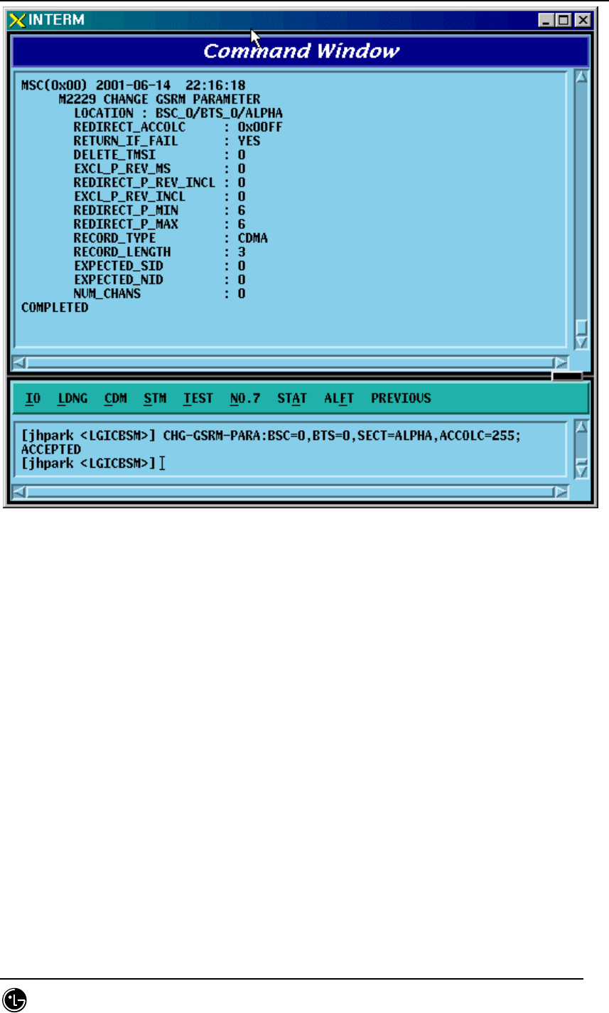
4.3.4.22. PC GLOBAL REDIRECT Parameter Information Change
To change Paging Channel Global Redirect information, click CDM-> Change_
Parameter_Information->CHG-GSRM-PARA on the Command Window in order. If the
next input window is displayed, then input the value to be changed.
• Command CHG-GSRM-PARA :BSC=a ,BTS=b ,SECT=c [,ACCOLC=d]
[,RET_IF_FAIL=e]
[,P_REV_MS=f] [,RDIR_P_REV=g] [,EXCL_P_REV=h] [,RDIR_P_MIN=i]
[,RDIR_P_MAX=j] [,RECORD_TYPE=k] [,RECORD_LEN=l]
[,EXPECT_A_SID=m] [,IGNORE_CDMA=n] [,SYS_ORDER=o]
[,BAND_CLASS=p] [,EXPECT_SID=q] [,EXPECT_NID=r] [,NUM_CHAN=s]
[,CDMA_CH_0=t] [,CDMA_CH_1=u] [,CDMA_CH_2=v]
[,CDMA_CH_3=w] [,CDMA_CH_4=x] [,CDMA_CH_5=y]
[,CDMA_CH_6=z] [,CDMA_CH_7=] [,CDMA_CH_8=] [,CDMA_CH_9=];
• Input CHG-GSRM-PARA :BSC=0 ,BTS=0 ,SECT=ALPHA,ACCOLC=255;
• Output
STAREX-IS BSM Manual
Page:278(877)
Issue:1.
0
SMD-011-PMA210
Fig. 4.3-92 PC Global Redirect Parameter Information Change Display

STAREX-IS BSM Manual
Page:279(877)
Issue:1.
0
SMD-011-PMA210
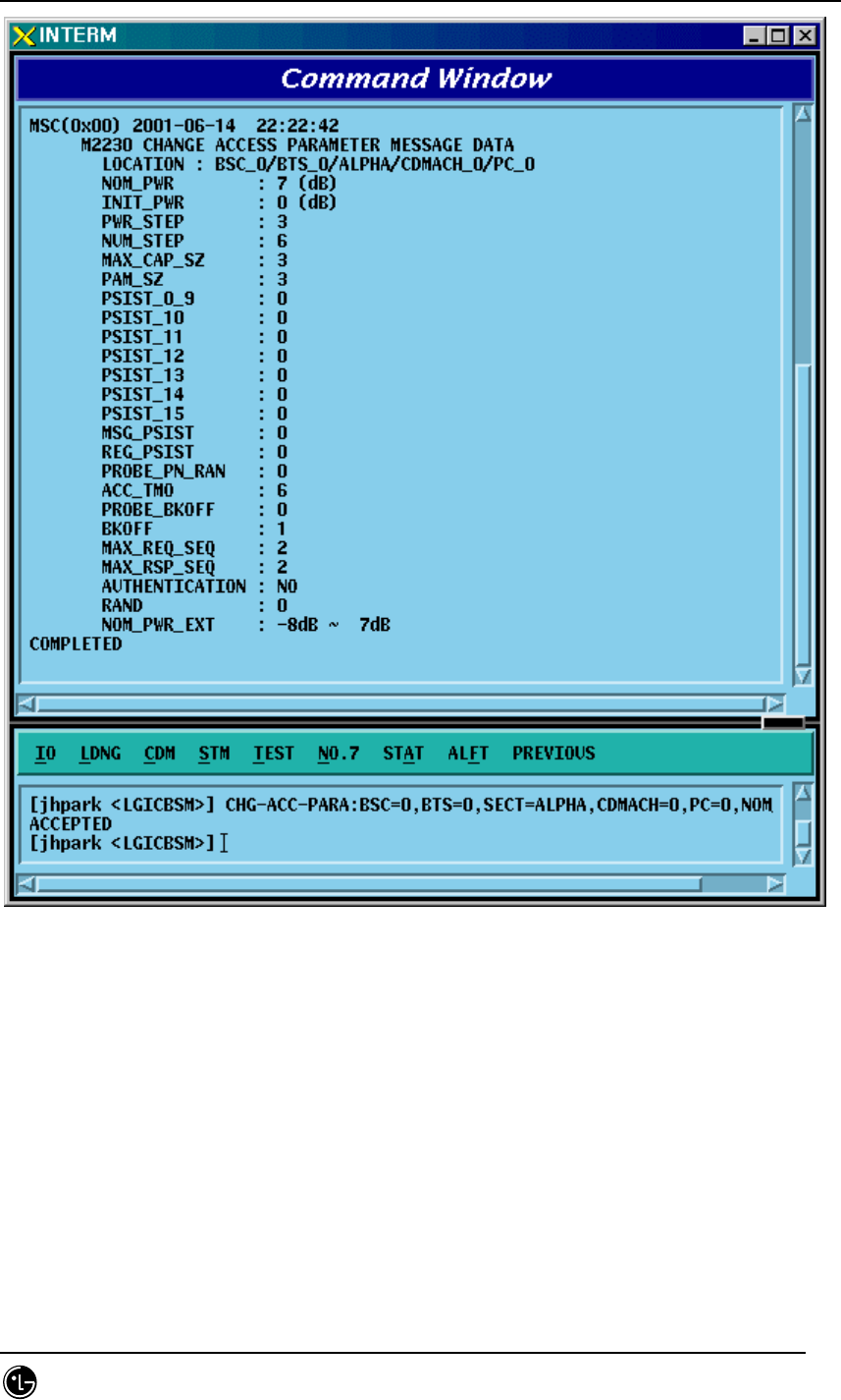
4.3.4.23. ACCESS PARAMETER Change
To change Access Parameter information, click CDM-> Change_
Parameter_Information->CHG-ACC-PARA on the Command Window in order. If the
next input window is displayed, then input the value to be changed.
• Command CHG-ACC-PARA :BSC=a ,BTS=b ,SECT=c ,CDMACH=d ,PC=e
[,NOM_PWR=f] [,INIT_PWR=g] [,PWR_STEP=h] [,NUM_STEP=i]
[,MAX_CAP_SZ=j] [,PAM_SZ=k] [,PSST_09=l] [,PSST_10=m]
[,PSST_11=n] [,PSST_12=o] [,PSST_13=p] [,PSST_14=q]
[,PSST_15=r] [,MSG_PSST=s] [,REG_PSST=t]
[,PRBE_RAN=u] [,ACC_TMO=v] [,PRBE_BKOF=w] [,BKOF=x]
[,MREQ_SEQ=y] [,MRSP_SEQ=z] [,AUTH=] [,RAND=]
[,NOM_PWR_EXT=];
• Input CHG-ACC-PARA :BSC=0 ,BTS=0,SECT=ALPHA ,CDMACH=0 ,PC=0
,NOM_PWR=7;
• Output
STAREX-IS BSM Manual
Page:280(877)
Issue:1.
0
SMD-011-PMA210
Fig. 4.3-93 Access Parameter Information Change Display
STAREX-IS BSM Manual
Page:281(877)
Issue:1.
0
SMD-011-PMA210
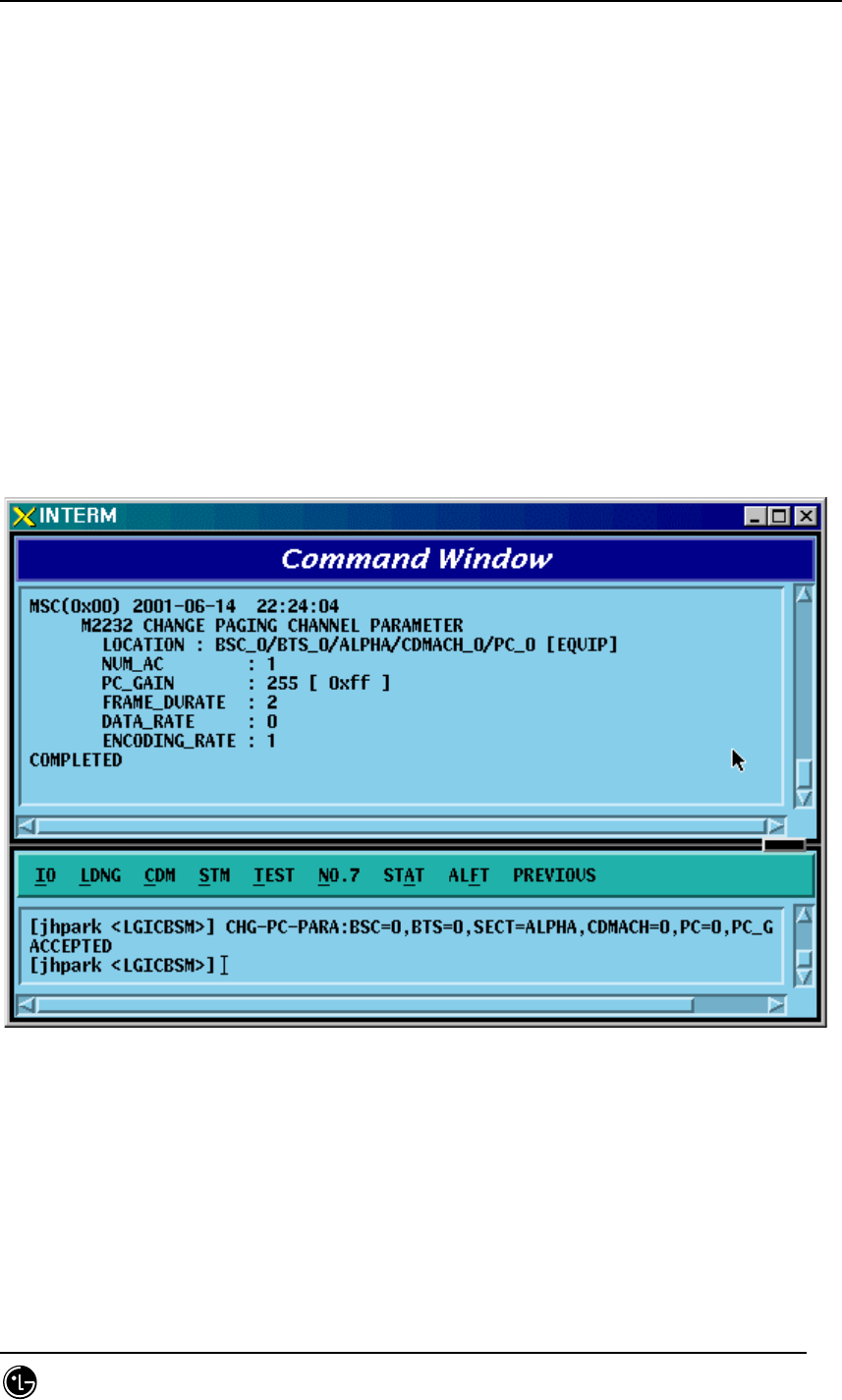
4.3.4.24. PAGING CHANNEL Parameter Information Change
To change Paging Channel Parameter information, click CDM-> Change_
Parameter_Information->CHG-PC-PARA on the Command Window in order. If the next
input window is displayed, then input the value to be changed.
• Command CHG-PC-PARA :BSC=a ,BTS=b ,SECT=c ,CDMACH=d ,PC=e
[,PC_GAIN=f] [,FRM_DUR=g] [,DATA_RATE=h];
• Input CHG-PC-PARA :BSC=0 ,BTS=0 ,SECT=ALPHA ,CDMACH=0 ,PC=0
,PC_GAIN=255;
• Output
Fig. 4.3-94 Paging Channel Parameter Information Display
STAREX-IS BSM Manual
Page:282(877)
Issue:1.
0
SMD-011-PMA210
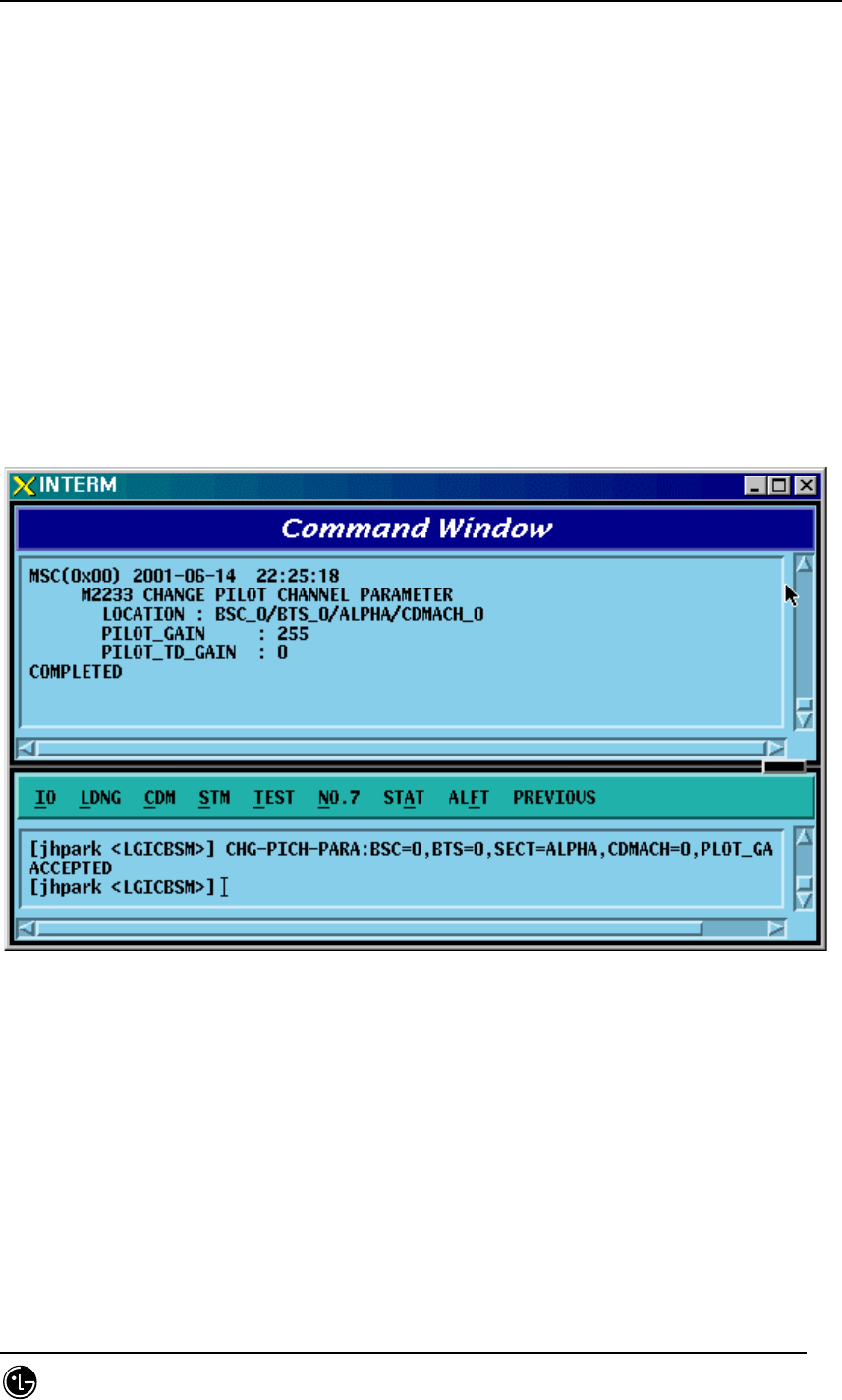
4.3.4.25. PILOT CHANNEL Parameter Information Change
To change Pilot Channel Parameter information, click CDM-> Change_
Parameter_Information->CHG-PICH-PARA on the Command Window in order. If the
next input window is displayed, then input the value to be changed.
• Command CHG-PICH-PARA :BSC=a ,BTS=b ,SECT=c ,CDMACH=d [,PLOT_GAIN=e]
[,PLOT_TD_GAIN=f];
• Input CHG-PICH-PARA :BSC=0 ,BTS=0 ,SECT=ALPHA ,
CDMACH=0,PLOT_GAIN=255;
• Output
Fig. 4.3-95 Pilot Channel Parameter Information Change Display
STAREX-IS BSM Manual
Page:283(877)
Issue:1.
0
SMD-011-PMA210
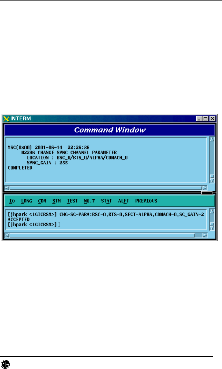
4.3.4.26. SYNC CHANNEL Parameter Information Change
To change Sync. Channel Parameter information, click CDM-> Change_
Parameter_Information->CHG-SC-PARA on the Command Window in order. If the next
input window is displayed, then input the value to be changed.
• Command CHG-SC-PARA :BSC=a ,BTS=b ,SECT=c ,CDMACH=d [,SC_GAIN=e];
• Input CHG-SC-PARA :BSC=0 ,BTS=b ,SECT=ALPHA ,CDMACH=0,SC_GAIN=255;
• Output
Fig. 4.3-96 Sync Channel Parameter Information Change Display
STAREX-IS BSM Manual
Page:284(877)
Issue:1.
0
SMD-011-PMA210
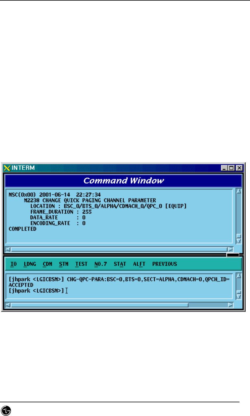
4.3.4.27. QUICH PAGING CHANNEL Parameter Information Change
To change Quick Paging Channel Parameter information, click CDM-> Change_
Parameter_Information->CHG-QPC-PARA on the Command Window in order. If the
next input window is displayed, then input the value to be changed.
• Command CHG-QPC-PARA :BSC=a ,BTS=b ,SECT=c ,CDMACH=d ,QPCH_ID=e
[,FRAME_DUR=f] [,DATA_RATE=g];
• Input CHG-QPC-PARA :BSC=0 ,BTS=0 ,SECT=ALPHA ,CDMACH=0 ,QPCH_ID=0
,FRAME_DUR=255;
• Output
Fig. 4.3-97 Quick Paging Channel Parameter Information Change Display
STAREX-IS BSM Manual
Page:285(877)
Issue:1.
0
SMD-011-PMA210
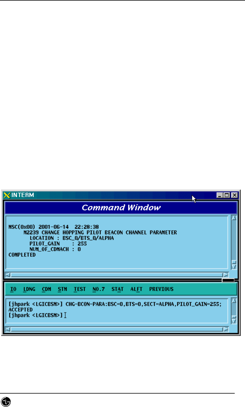
4.3.4.28. HOPPING PILOT BEACON CHANNEL Parameter Information
Change
To change Hopping Pilot Beacon Channel Parameter information, click CDM->
Change_ Parameter_Information->CHG-BCON-PARA on the Command Window in
order. If the next input window is displayed, then input the value to be changed.
• Command CHG-BCON-PARA :BSC=a ,BTS=b ,SECT=c [,PILOT_GAIN=d]
[,NUM_CDMA_CH=e] [,CDMA_FREQ1=f] [,CDMA_FREQ2=g]
[,CDMA_FREQ3=h] [,CDMA_FREQ4=i] [,CDMA_FREQ5=j]
[,CDMA_FREQ6=k] [,CDMA_FREQ7=l] [,CDMA_FREQ8=m]
[,CDMA_FREQ9=n] [,CDMA_FREQ10=o]
[,CDMA_FREQ11=p] [,CDMA_FREQ12=q];
• Input CHG-BCON-PARA :BSC=0 ,BTS=0 ,SECT=ALPHA ,PILOT_GAIN=255;
• Output
Fig. 4.3-98 Hopping Pilot Beacon Channel Parameter Information Change Display
STAREX-IS BSM Manual
Page:286(877)
Issue:1.
0
SMD-011-PMA210
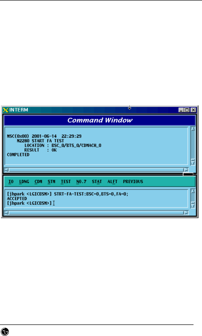
4.3.4.29. CDMA Channel FA Test Start
To start the CDMA Channel FA test, click CDM-> Change_ Parameter_Information-
>STRT-FA-TEST on the Command Window in order. If the next input window is
displayed, then input the value to be changed.
• Command STRT-FA-TEST :BSC=a ,BTS=b ,FA=c;
• Input STRT-FA-TEST :BSC=0 ,BTS=0 ,FA=0;
• Output
Fig. 4.3-99 CDMA Channel FA Test Start Display
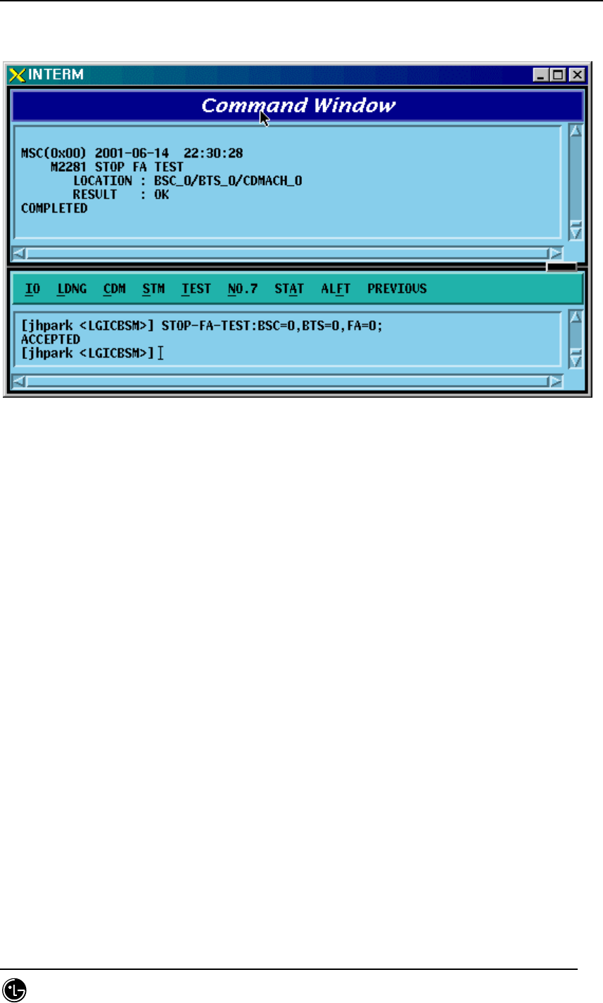
4.3.4.30. Termination of CDMA Channel FA Test
To stop the CDMA Channel FA test, click CDM-> Change_ Parameter_Information-
>STOP-FA-TEST on the Command Window in order. If the next input window is
displayed, then input the value to be changed.
• Command STOP-FA-TEST :BSC=a ,BTS=b ,FA=c;
• Input STOP-FA-TEST :BSC=0,BTS=0 ,FA=0;
STAREX-IS BSM Manual
Page:287(877)
Issue:1.
0
SMD-011-PMA210
• Output
Fig. 4.3-100 CDMA Channel FA Test Termination Display

STAREX-IS BSM Manual
Page:288(877)
Issue:1.
0
SMD-011-PMA210
4.3.5. Parameter Information Change Command
(Change_Parameter_Information_2)
This section describes commands that are used to change the parameter information
that is inquired (required). The command to change parameter information cannot be
easily input by the keyboard since input parameter counts are too many. For this
reason, this section will skip the command input in text and demonstrate window input
by mouse. Upon inputting the command, the part in blue is the parameter that the user
can change and the user can change part or entire fields among them. For more
information on parameters for each command, refer to the test procedures.
.
Table 4.3-2 Parameter Information Change Command (2) List
CRN MMC Description
2240 CHG-DORM-DATA Dormant Timer Change
2241 CHG-PKZN-DATA PACKET ZONE DATA Change
2243 CHG-FAC-TIMER FACILITIES MANAGEMENT TIMER Change
2244 CHG-HO-TIMER HANDOFF TIMER Change
2245 CHG-SUP-TIMER BSC SUPPLEMENT SERVICES TIMER Change
2246 CHG-CALL-TIMER BSC CALL PROCESSING TIMER Change
2247 CHG-MOB-TIMER BSC MOBILITY MANAGEMENT TIMER Change
2248 CHG-A89-TIMER A8 A9 INTERFACE TIMER Change
2249 CHG-A37-TIMER A3, A7 INTERFACE TIMER Change
2250 CHG-RS1-FWDP Forward Link Power Management Information (RS1)
change
2251 CHG-RS1-REVP Backward (or Reverse) Link Power Management
Information (RS1) change
2255 CHG-RS2-FWDP Forward Link Power Management Information (RS2)
change
2256 CHG-RS2-REVP Backward (or Reverse) Link Power Management
Information (RS2) change
2257 CHG-FER-PARA Service Option FER Change
2261 CHG-MAHO-DATA MAHHO DATA change
2262 CHG-LOC-PARA LOCATION PARA information change
2263 CHG-SCH-PARA SCH parameter information change
2265 CHG-PWR1-CTRL POWER CONTROL parameter information (1) change
STAREX-IS BSM Manual
Page:289(877)
Issue:1.
0
SMD-011-PMA210
2266 CHG-PWR2-CTRL POWER CONTROL parameter information (2) change
2267 CHG-PWR3-CTRL POWER CONTROL parameter information (3) change
2271 CHG-BTS-NAME BTS name change
2292 CHG-PCF-TIMER PCF TIMER change
2294 CHG-PCP-ADDR PCP/PMP ADDRESS change
2295 CHG-PIP-ADDR PIP ADDRESS change
2296 CHG-PCF-PARA PCF PARAMETER change
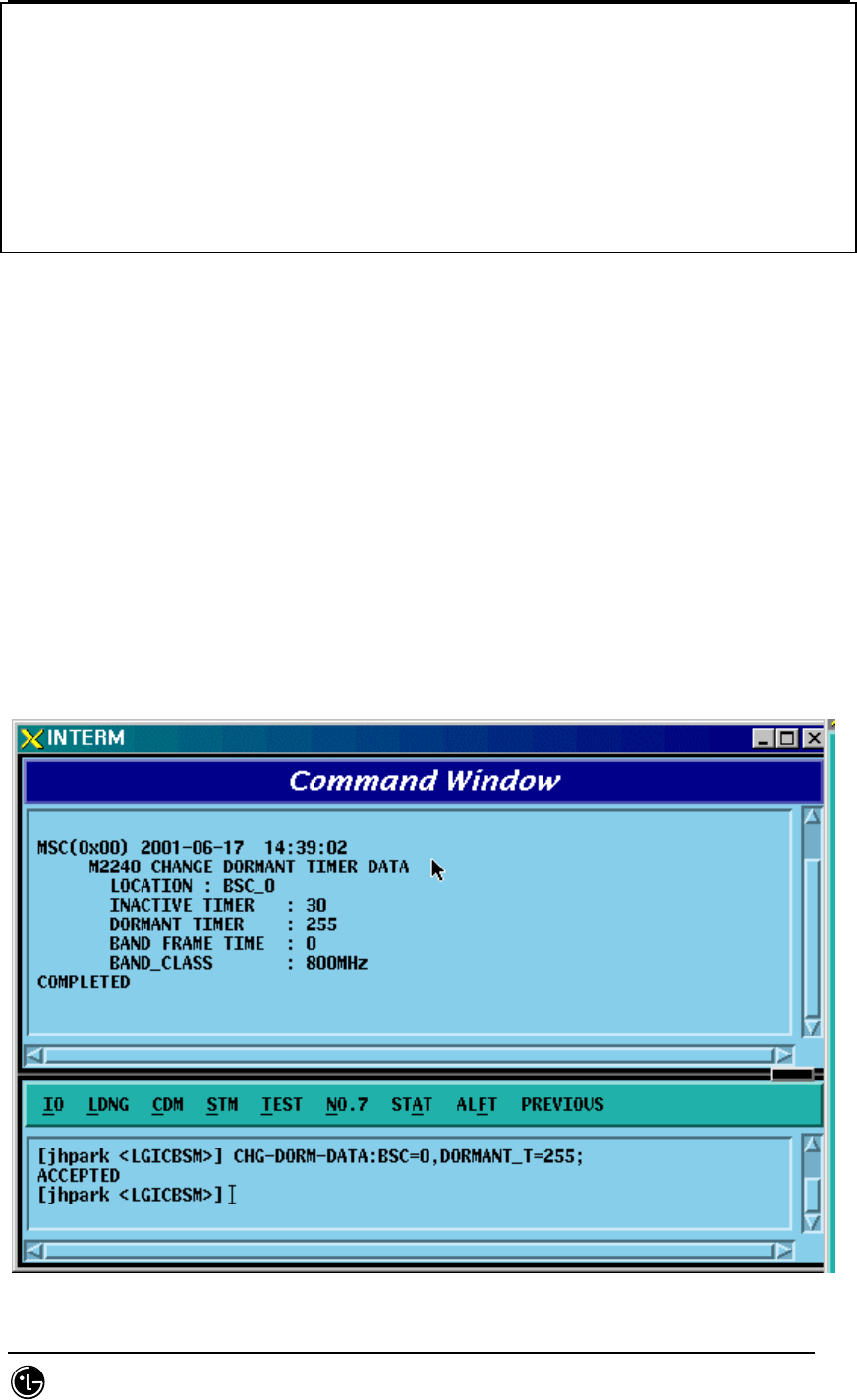
4.3.5.1. Dormant Timer Change
To change Dormant Timer, click CDM->Change_Parameter_ Information_2-> CHG-
DORM-DATA on the Command Window in order. Input the value to be changed in each
field.
• Command CHG-DORM-DATA :BSC=a [,DORMANT_T=b] [,INACTIVE_T=c]
[,BAND_FRAME_T=d] [,BAND_CLASS=e] ;
• Input CHG-DORM-DATA :BSC=0,DORMANT_T=255;
• Command
STAREX-IS BSM Manual
Page:290(877)
Issue:1.
0
SMD-011-PMA210
Fig. 4.3-101 Dormant Timer Change Display
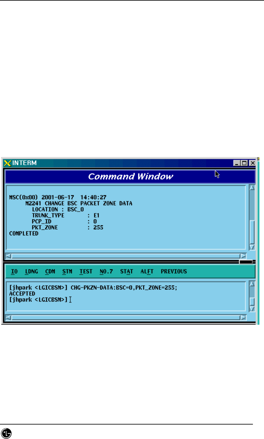
4.3.5.2. PACKET ZONE DATA Change
To change PACKET ZONE DATA, click CDM->Change_Parameter_ Information_2->
CHG-PKZN-DATA on the Command Window in order. Input the value to be changed in
each field as shown below.
• Command CHG-PKZN-DATA :BSC=a [,PKT_ZONE=b] [,PCP_ID=c];
• Input CHG-PKZN-DATA :BSC=0,PKT_ZONE=255;
• Output
Fig. 4.3-102 Packet Zone Data Change Display
STAREX-IS BSM Manual
Page:291(877)
Issue:1.
0
SMD-011-PMA210
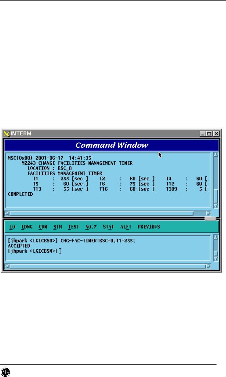
4.3.5.3. FACILITIES MANAGEMENT TIMER Change
To change FACILITIES MANAGEMENT TIMER, click CDM->Change_Parameter_
Information_2-> CHG-FAC-TIMER on the Command Window in order. Input the value
to be changed in each field as shown below.
• Command CHG-FAC-TIMER :BSC=a [,T1=b] [,T2=c] [,T4=d] [,T5=e]
[,T6=f] [,T12=g] [,T13=h] [,T16=i] [,T309=j];
• Input CHG-FAC-TIMER :BSC=0,T1=255;
• Output
Fig. 4.3-103 Facilities Management Timer Change Display
STAREX-IS BSM Manual
Page:292(877)
Issue:1.
0
SMD-011-PMA210
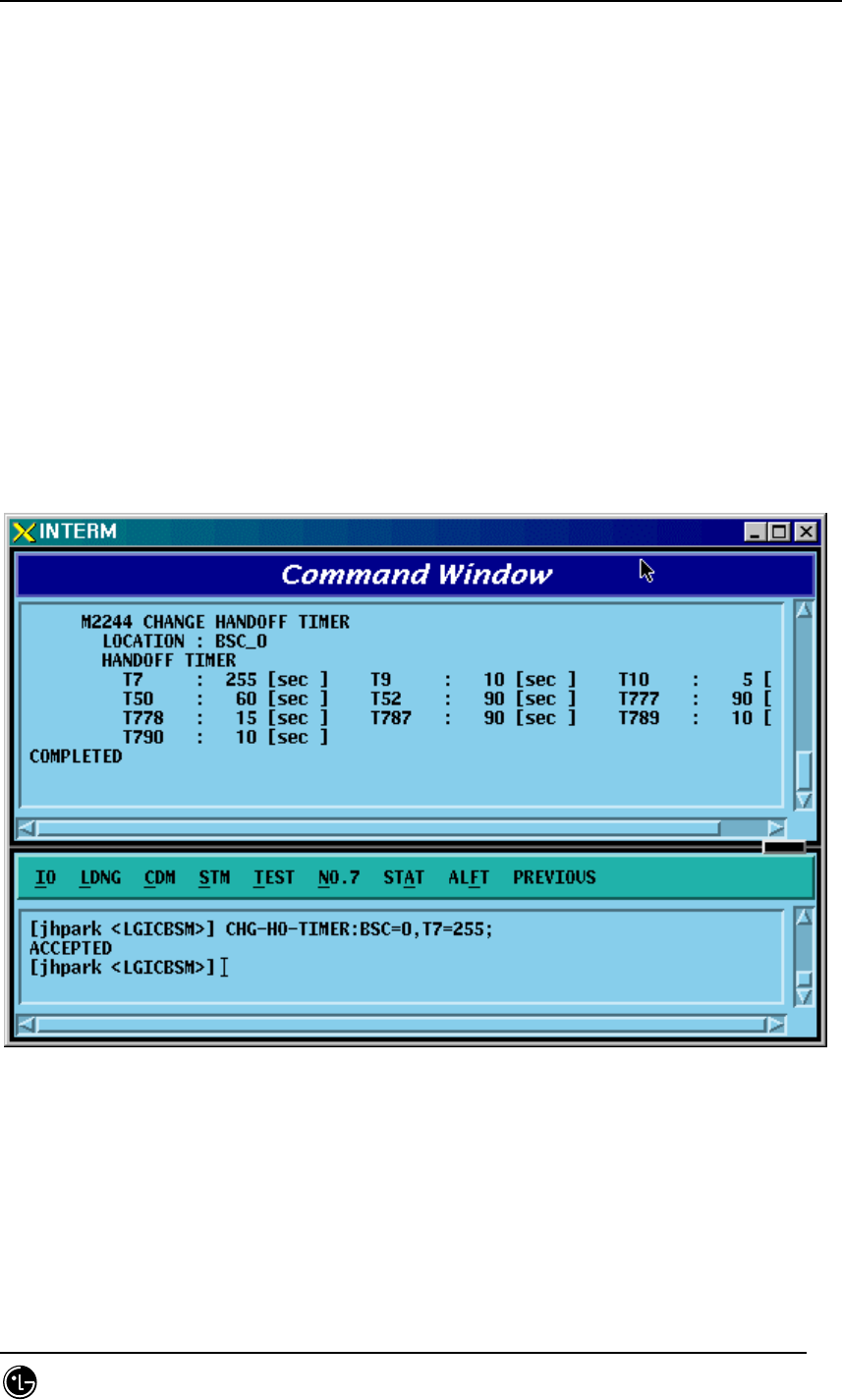
4.3.5.4. HANDOFF TIMER Change
To change HANDOFF TIMER, click CDM->Change_Parameter_ Information_2-> CHG-
HO-TIMER on the Command Window in order. Input the value to be changed in each
field as shown below.
• Command CHG-HO-TIMER :BSC=a [,T7=b] [,T9=c] [,T10=d] [,T50=e]
[,T52=f] [,T777=g] [,T778=h] [,T787=i] [,T789=j]
[,T790=k];
• Input CHG-HO-TIMER :BSC=0,T7=255;
• Output
FIG 4.3-104 Handoff Timer Change Display
STAREX-IS BSM Manual
Page:293(877)
Issue:1.
0
SMD-011-PMA210
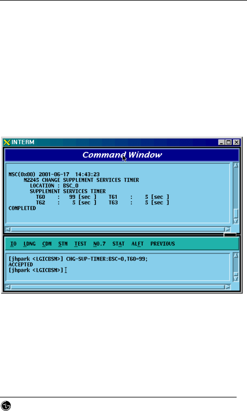
4.3.5.5. BSC SUPPLEMENT SERVICES TIMER Change
To change BSC SUPPLEMENT SERVICES TIMER, click CDM->Change_Parameter_
Information_2-> CHG-SUP-TIMER on the Command Window in order. Input the value
to be changed in each field as shown below.
• Command CHG-SUP-TIMER :BSC=a [,T60=b] [,T61=c] [,T62=d] [,T63=e] ;
• Input CHG-SUP-TIMER :BSC=0,T60=99;
• Output
Fig. 4.3-105 BSC Supplement Services Timer Change Display
STAREX-IS BSM Manual
Page:294(877)
Issue:1.
0
SMD-011-PMA210
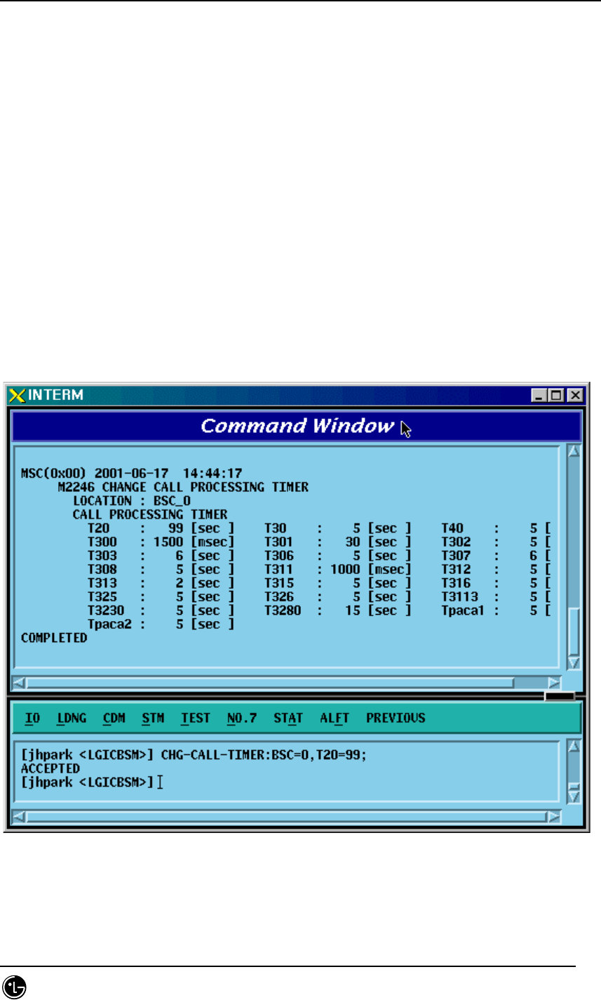
4.3.5.6. BSC CALL PROCESSING TIMER Change
To change BSC CALL PROCESSING TIMER, click CDM->Change_Parameter_
Information_2-> CHG-CALL-TIMER on the Command Window in order. Input the value
to be changed in each field as shown below.
• Command CHG-CALL-TIMER :BSC=a [,T20=b] [,T30=c] [,T40=d] [,T300=e]
[,T301=f] [,T302=g] [,T303=h] [,T306=i] [,T307=j]
[,T308=k] [,T311=l] [,T312=m] [,T313=n] [,T315=o]
[,T316=p] [,T325=q] [,T326=r] [,T3113=s] [,T3230=t]
[,T3280=u] [,Tpaca1=v] [,Tpaca2=w];
• Input CHG-CALL-TIMER :BSC=0,T20=99;
• Output
Fig. 4.3-106 BSC Call Processing Timer Change Display
STAREX-IS BSM Manual
Page:295(877)
Issue:1.
0
SMD-011-PMA210
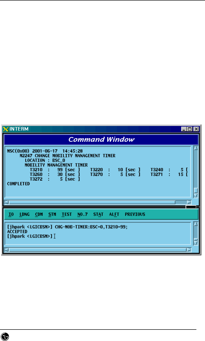
4.3.5.7. BSC MOBILITY MANAGEMENT TIMER Change
To change BSC MOBILITY MANAGEMENT TIMER, click CDM->Change_Parameter_
Information_2-> CHG-MOB-TIMER on the Command Window in order. Input the value
to be changed in each field as shown below.
• Command CHG-MOB-TIMER :BSC=a [,T3210=b] [,T3220=c] [,T3240=d]
[,T3260=e]
[,T3270=f] [,T3271=g] [,T3272=h];
• Input CHG-MOB-TIMER :BSC=0,T3210=99;
• Output
Fig. 4.3-107 BSC Mobility Management Timer Change Display
STAREX-IS BSM Manual
Page:296(877)
Issue:1.
0
SMD-011-PMA210
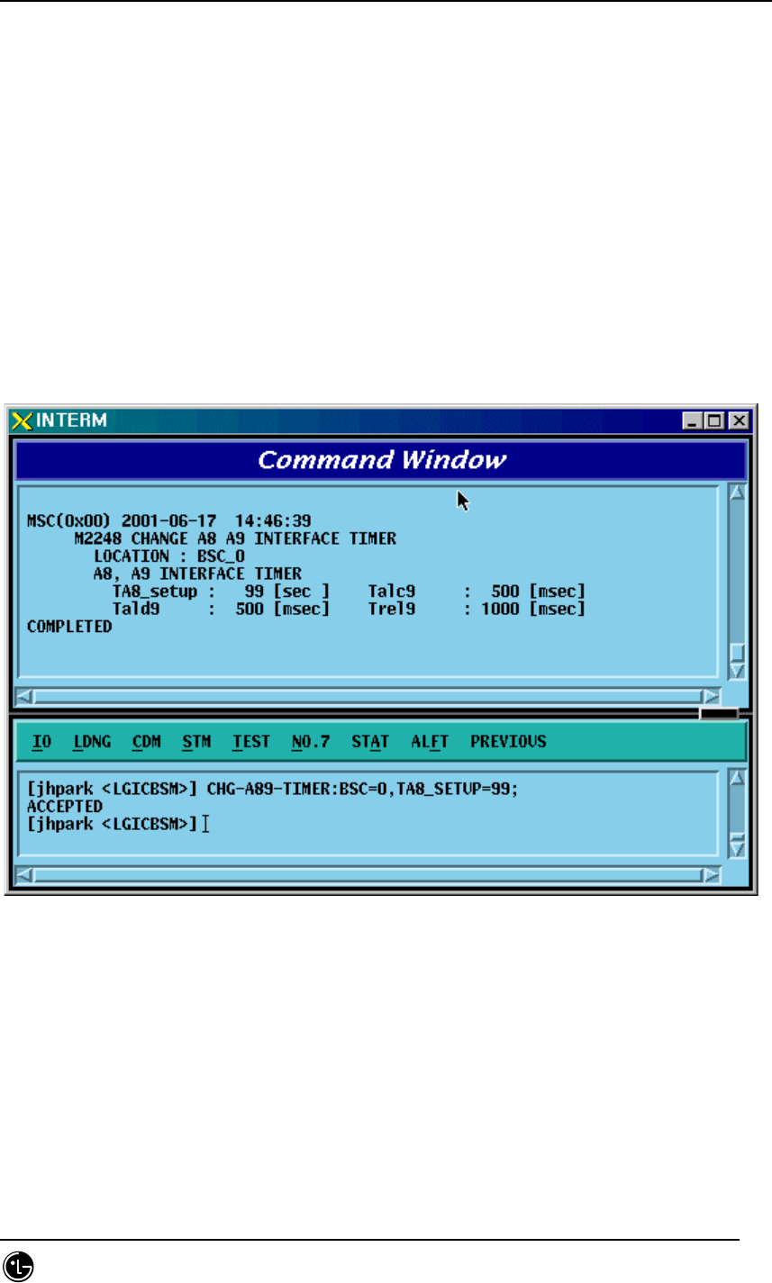
4.3.5.8. A8 A9 INTERFACE TIMER Change
To change A8 A9 INTERFACE TIMER, click CDM->Change_Parameter_
Information_2_2-> CHG-A89-TIMER on the Command Window in order. Input the
value to be changed in each field as shown below.
• Command CHG-A89-TIMER :BSC=a [,TA8_SETUP=b] [,Talc9=c] [,Tald9=d]
[,Trel9=e];
• Input CHG-A89-TIMER :BSC=0,TA8_SETUP=99;
• Output
Fig. 4.3-108 A8 A9 INTERFACE TIMER Change
STAREX-IS BSM Manual
Page:297(877)
Issue:1.
0
SMD-011-PMA210
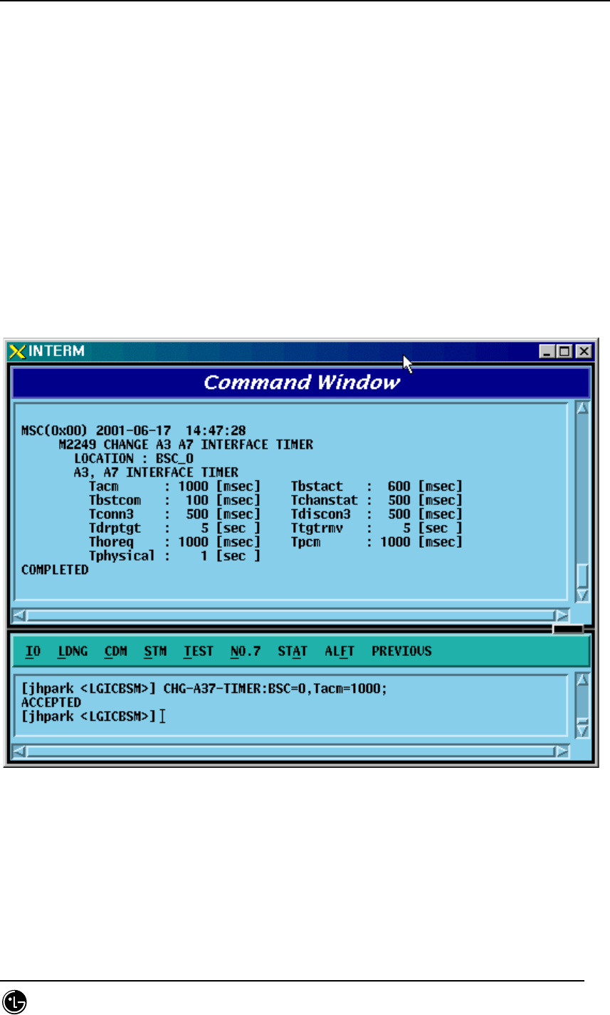
4.3.5.9. A3, A7 INTERFACE TIMER Change
To change A3 A7 INTERFACE TIMER, click CDM->Change_Parameter_
Information_2_2-> CHG-A37-TIMER on the Command Window in order. Input the
value to be changed in each field as shown below.
• Command CHG-A37-TIMER :BSC=a [,Tacm=b] [,Tbstact=c] [,Tbsccom=d]
[,Tchanstat=e] [,Tconn3=f] [,Tdiscon3=g] [,Tdrptgt=h] [,Ttgtrmv=i]
[,Thoreq=j] [,Tpcm=k] [,Tphysical=l];
• Input CHG-A37-TIMER :BSC=0,Tacm=1000;
• Output
Fig. 4.3-109 A3, A7 INTERFACE TIMER Change
STAREX-IS BSM Manual
Page:298(877)
Issue:1.
0
SMD-011-PMA210
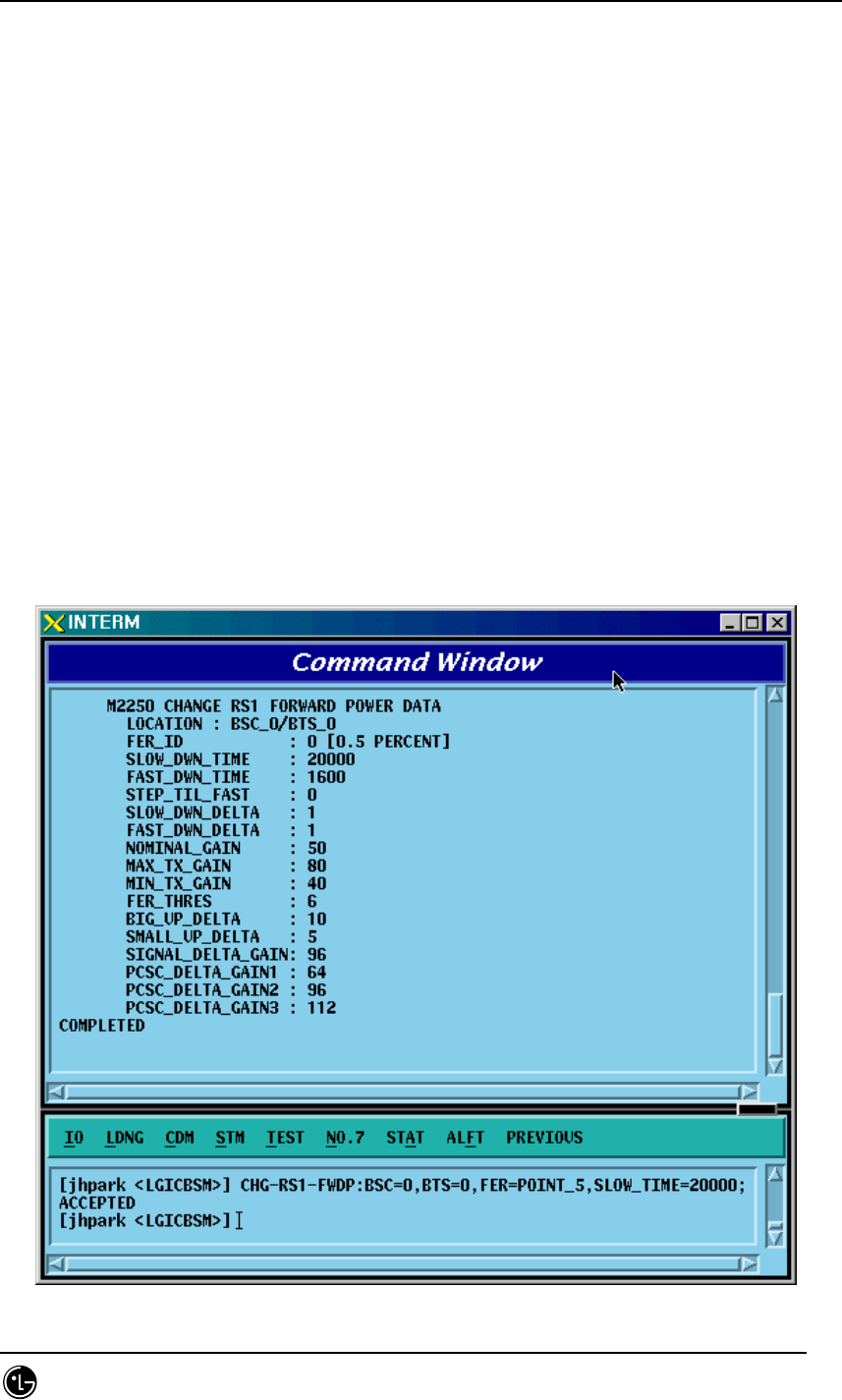
4.3.5.10. Forward Link Power Management Information (RS1) Change
To change forward link power management information (RS1), click CDM-
>Change_Parameter_ Information_2_2-> CHG-RS1-FWDP on the Command Window in
order. Input the value to be changed in each field as shown below.
• Command CHG-RS1-FWDP :BSC=a ,BTS=b ,FER=c [,SLOW_TIME=d]
[,FAST_TIME=e]
[,STEP_FAST=f] [,SLOW_DLTA=g] [,FAST_DLTA=h] [,NOM_GAIN=i]
[,MAX_TC_GAIN=j] [,MIN_TC_GAIN=k] [,FER_THRE=l]
[,BGUP_DLTA=m] [,SMLL_DLTA=n] [,SIGL_DLTA=o]
[,DLTA_GAN1=p] [,DLTA_GAN2=q] [,DLTA_GAN3=r];
• Input CHG-RS1-FWDP :BSC=0 ,BTS=0 ,FER=POINT_5,SLOW_TIME=20000;
• Output
STAREX-IS BSM Manual
Page:299(877)
Issue:1.
0
SMD-011-PMA210
Fig. 4.3-110 Forward Link Power Management Information (RS1) Change
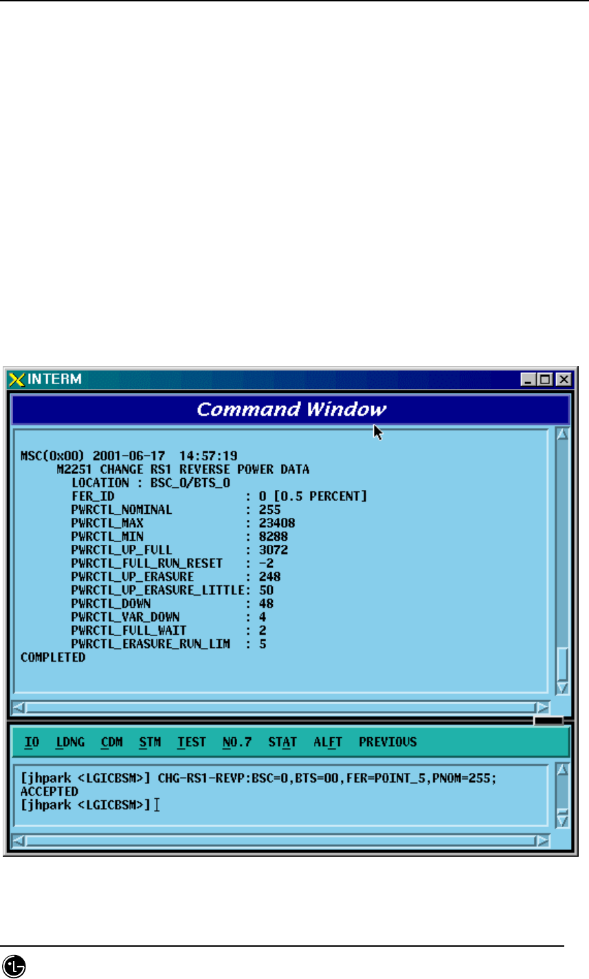
4.3.5.11. Backward Link Power Management Information (RS1) Change
To change Backward link power management information (RS1), click CDM-
>Change_Parameter_ Information_2_2-> CHG-RS1-REVP on the Command Window in
order. Input the value to be changed in each field as shown below.
• Command CHG-RS1-REVP :BSC=a ,BTS=b ,FER=c [,PNOM=d] [,PMAX=e]
[,PMIN=f] [,PUPF=g] [,PFRR=h] [,PUPE=i] [,PUPEL=j]
[,PD=k] [,PVD=l] [,PFW=m] [,PERL=n];
• Input CHG-RS1-REVP :BSC=0 ,BTS=0 ,FER=POINT_5,PNOM= 255;
• Output
Fig. 4.3-111 Backward Link Power Management Information (RS1) Change

STAREX-IS BSM Manual
Page:300(877)
Issue:1.
0
SMD-011-PMA210
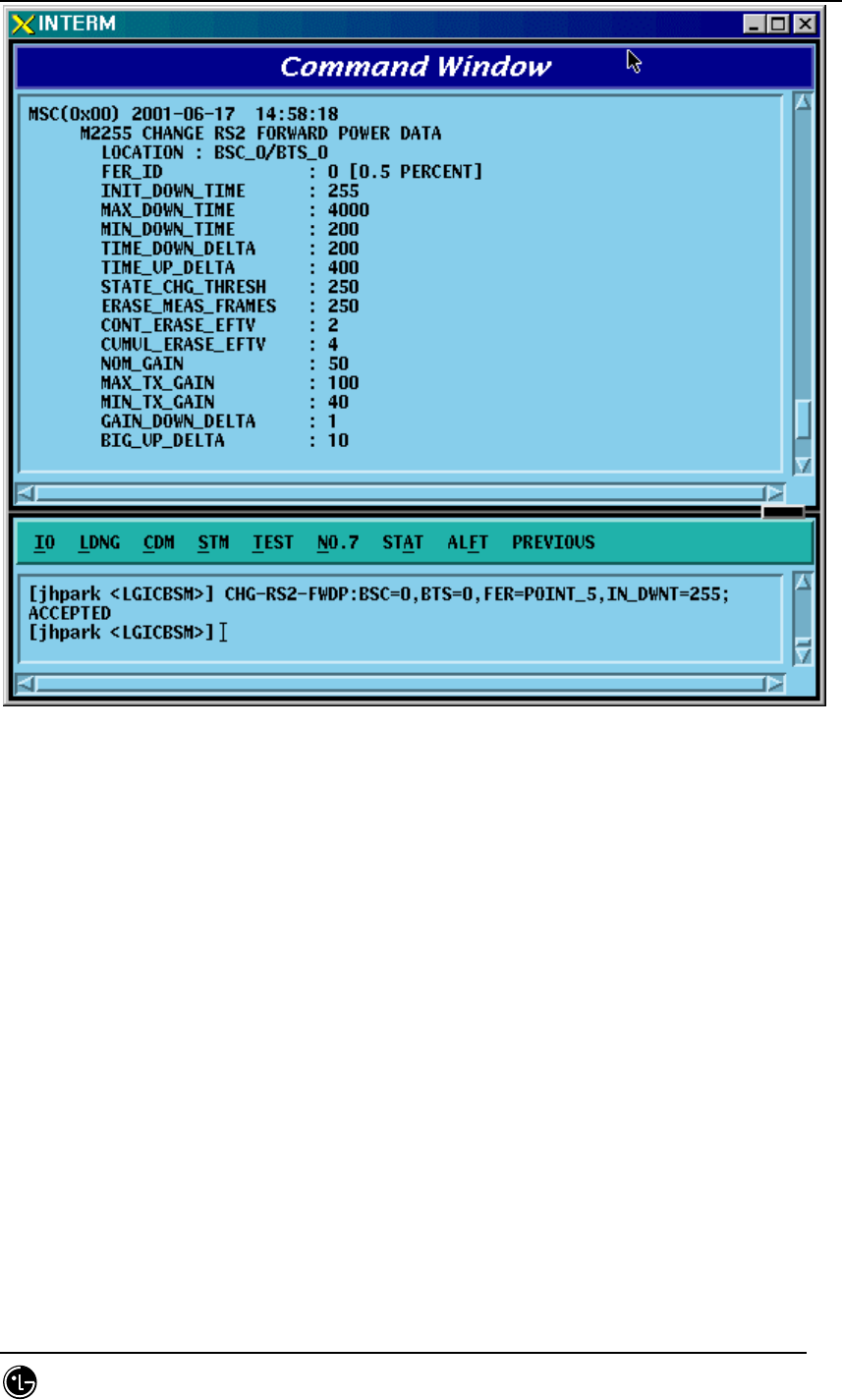
4.3.5.12. Forward Link Power Management Information (RS2) Change
To change Forward link power management information (RS2), click CDM-
>Change_Parameter_ Information_2_2-> CHG-RS2-FWDP on the Command Window in
order. Input the value to be changed in each field as shown below.
• Command CHG-RS2-FWDP :BSC=a ,BTS=b ,FER=c [,IN_DWNT=d]
[,MAX_DWNT=e]
[,MIN_DWNT=f] [,TDWN_DLT=g] [,TUP_DLT=h] [,STT_THS=i]
[,ERA_MSR=j] [,CONT_ERA=k] [,CUMU_ERA=l] [,NOM_GAIN=m]
[,MAX_TX_GAIN=n] [,MIN_TX_GAIN=o] [,GAIN_DWN=p]
[,BIG_UP=q] [,SMALL_UP=r] [,SIGL_DLT=s] [,DLT_GAN1=t]
[,DLT_GAN2=u] [,DLT_GAN3=v];
• Input CHG-RS2-FWDP :BSC=0 ,BTS=0 ,FER=POINT_5,IN_DWNT=255;
• Output
STAREX-IS BSM Manual
Page:301(877)
Issue:1.
0
SMD-011-PMA210
Fig. 4.3-112 Forward Link Power Management Information (RS2) Change
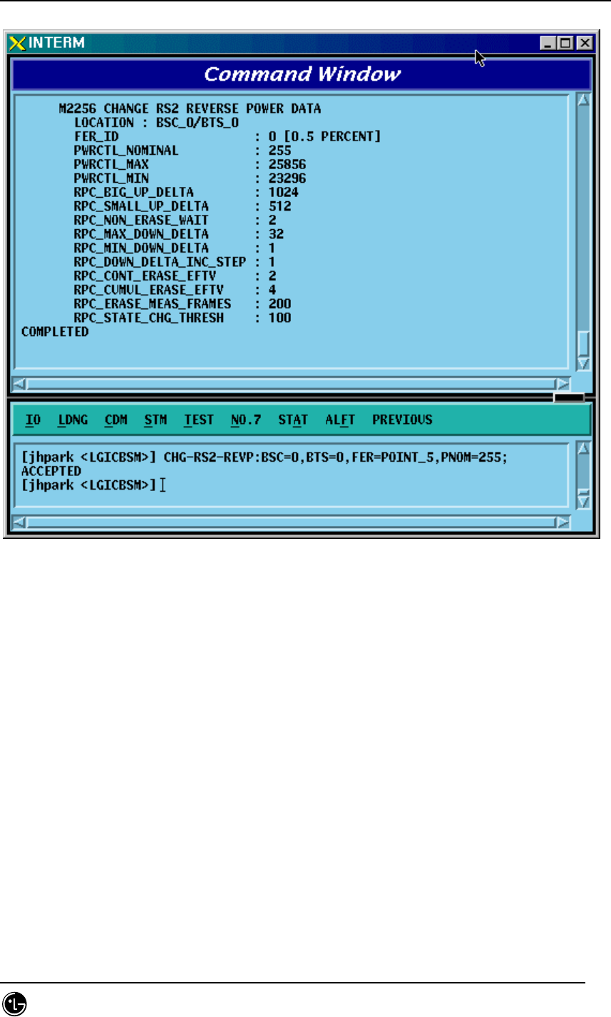
4.3.5.13. Backward Link Power Management Information (RS2) Change
To change Backward link power management information (RS2), click CDM-
>Change_Parameter_ Information_2_2-> CHG-RS2-REVP on the Command Window in
order. Input the value to be changed in each field as shown below.
• Command CHG-RS2-REVP :BSC=a ,BTS=b ,FER=c [,PNOM=d] [,PMAX=e]
[,PMIN=f] [,RBUD=g] [,RSUD=h] [,RNEW=i] [,RMAXDD=j]
[,RMINDD=k] [,RDDIS=l] [,RCONTEE=m] [,RCUMULEE=n] [,REMF=o]
[,RSCT=p];
• Input CHG-RS2-REVP :BSC=0 ,BTS=0 ,FER=POINT_5,PNOM=255;
• Output
STAREX-IS BSM Manual
Page:302(877)
Issue:1.
0
SMD-011-PMA210
Fig. 4.3-113 Backward Link Power Management Information (RS2) Change

STAREX-IS BSM Manual
Page:303(877)
Issue:1.
0
SMD-011-PMA210
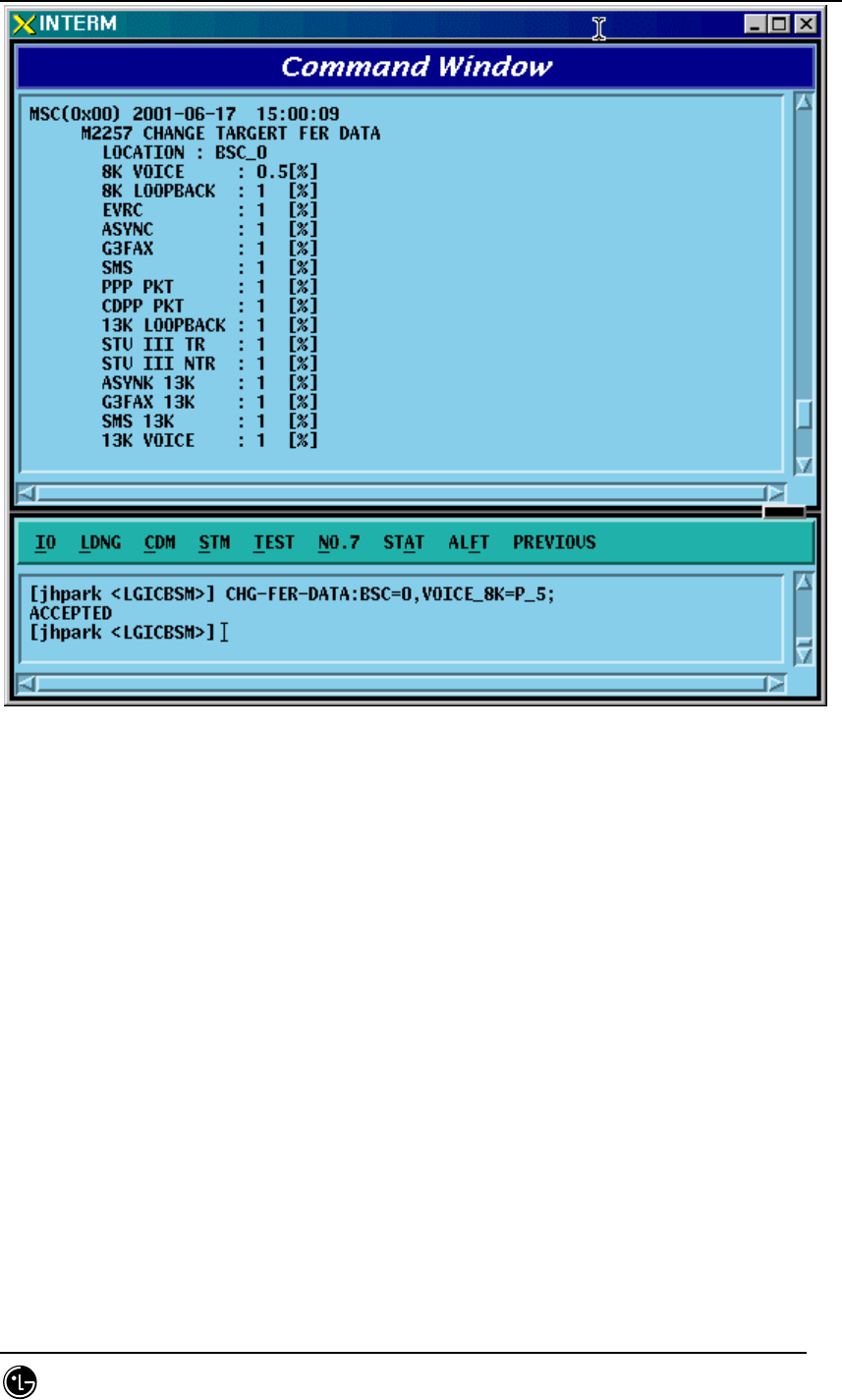
4.3.5.14. Service Option FER Change
To change Service Option FER, click CDM->Change_Parameter_ Information_2_2->
CHG-FER-PARA on the Command Window in order. Input the value to be changed in
each field as shown below.
• Command CHG-FER-DATA :BSC=a [,VOICE_8K=b] [,LOOPBK_8K=c] [,EVRC=d]
[,ASYNC=e] [,G3FAX=f] [,SMS=g] [,PPP_PKT=h] [,CDPP_PKT=i]
[,LOOPBK_13K=j] [,STU_TR=k] [,STU_NTR=l] [,ASYNC_13K=m]
[,G3FAX_13K=n] [,SMS_13K=o] [,VOICE_13K=p] [,IS96_VOICE=q]
[,MARKOV_8K=r] [,DATA=s] [,IS96A_1BY8=t]
[,MARKOV_13K=u] [,WLL_OFFHOOK=v] [,RS1_MARKOV=w]
[,RS2_MARKOV=x] [,FCH=y]
[,SCH=z] [,DCCH=] [,SCH_LB=] [,SCH_LB2=];
• Input CHG-FER-DATA :BSC=0,VOICE_8K=P_5;
• Output
STAREX-IS BSM Manual
Page:304(877)
Issue:1.
0
SMD-011-PMA210
Fig. 4.3-114 Service Option FER Change
STAREX-IS BSM Manual
Page:305(877)
Issue:1.
0
SMD-011-PMA210
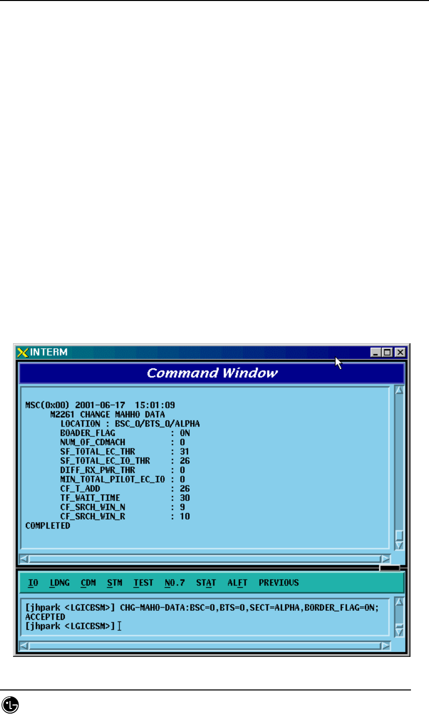
4.3.5.15. MAHHO DATA Change
To change MAHHO DATA, click the CDM->Change_Parameter_ Information_2->
CHG-MAHO-DATA on the Command Window in order. Input the value to be changed
in each file as shown below.
• Command CHG-MAHO-DATA :BSC=a ,BTS=b ,SECT=c [,BORDER_FLAG=d]
[,BD_CLS=e]
[,NUM_CHAN=f] [,CDMA_FREQ0=g] [,CDMA_FREQ1=h] [,CDMA_FREQ2=i]
[,CDMA_FREQ3=j] [,CDMA_FREQ4=k] [,CDMA_FREQ5=l]
[,CDMA_FREQ6=m] [,CDMA_FREQ7=n] [,CDMA_FREQ8=o]
[,CDMA_FREQ9=p] [,CDMA_FREQ10=q] [,CDMA_FREQ11=r] [,STET=s]
[,STEIT=t] [,DRPT=u] [,MIN_TOT=v] [,CF_T_ADD=w]
[,TF_WAIT_TIME=x] [,SRCH_N=y] [,SRCH_R=z];
• Input CHG-MAHO-DATA :BSC=0 ,BTS=0 ,SECT=ALPHA,BORDER_FLAG=ON;
• Output

STAREX-IS BSM Manual
Page:306(877)
Issue:1.
0
SMD-011-PMA210
Fig. 4.3-115 MAHHO DATA Change
STAREX-IS BSM Manual
Page:307(877)
Issue:1.
0
SMD-011-PMA210
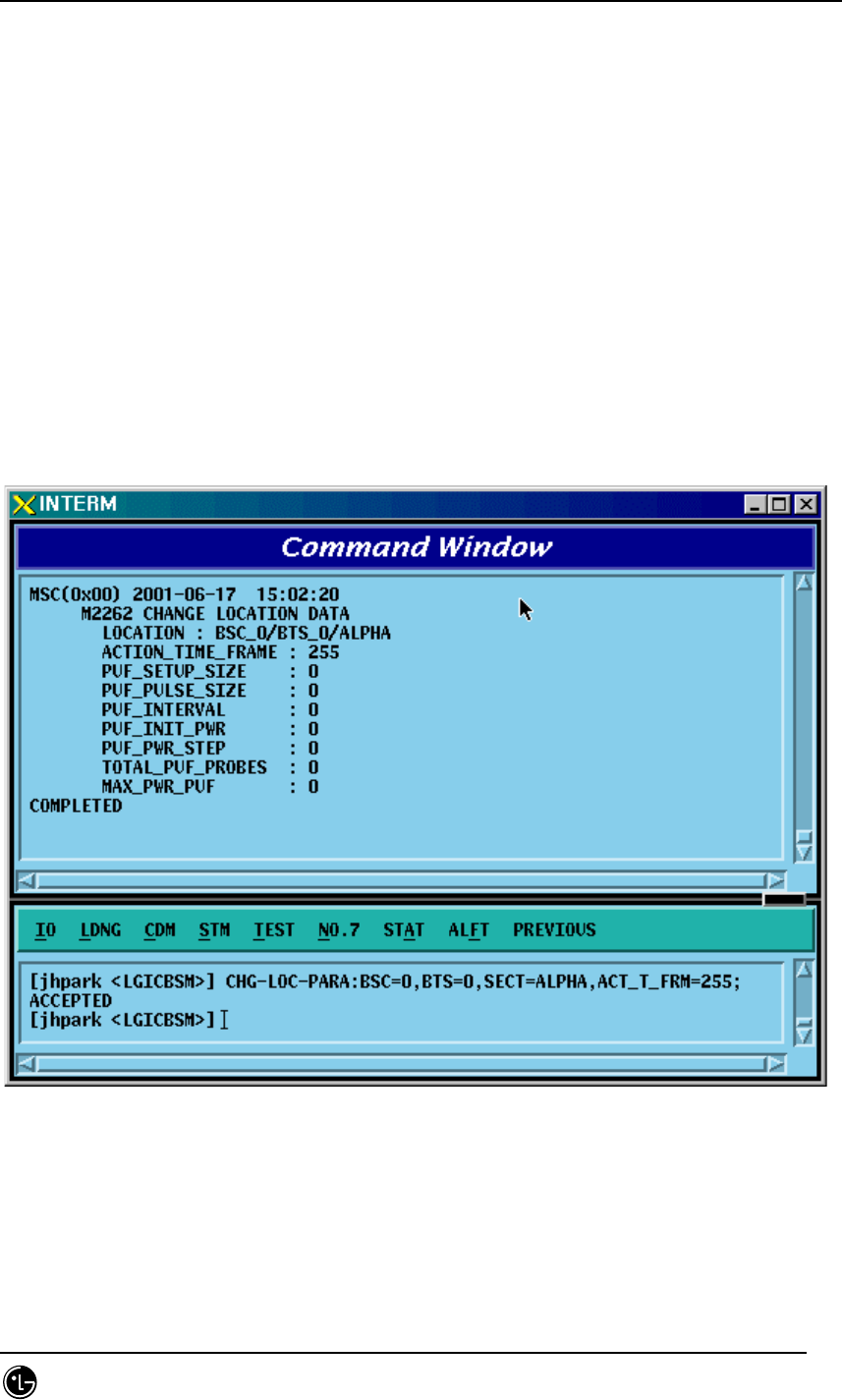
4.3.5.16. LOCATION PARA Information Change
To change LOCATION PARA information, click CDM->Change_Parameter_
Information_2-> CHG-LOC-PARA on the Command Window in order. Input the value
to be changed in each field as shown below.
• Command CHG-LOC-PARA :BSC=a ,BTS=b ,SECT=c [,ACT_T_FRM=d]
[,PUF_ST_SZ=e][,PUF_P_SZ=f] [,PUF_INTERVAL=g] [,PUF_I_PWR=h]
[,PUF_P_STEP=i] [,TOT_PUF_P=j] [,MAX_PWR_PUF=k];
• Input CHG-LOC-PARA :BSC=0 ,BTS=0 ,SECT=ALPHA,ACT_T_FRM=ON;
• Output
Fig. 4.3-116 LOCATION PARA Information Change
STAREX-IS BSM Manual
Page:308(877)
Issue:1.
0
SMD-011-PMA210
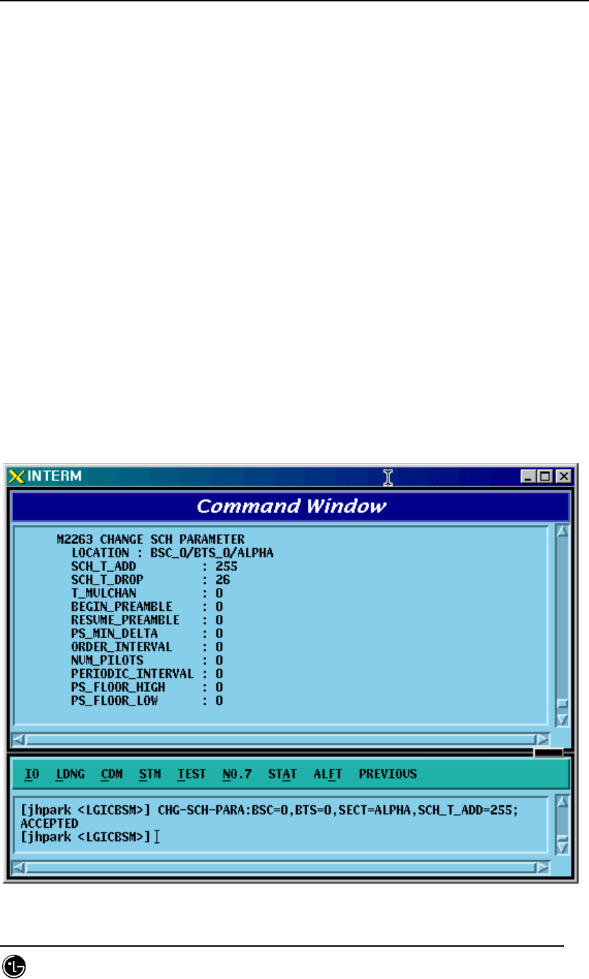
4.3.5.17. SCH Parameter Information Change
To change SCH PARA information, click CDM->Change_Parameter_ Information_2->
CHG-SCH-PARA on the Command Window in order. Input the value to be changed in
each field as shown below.
• Command CHG-SCH-PARA :BSC=a ,BTS=b ,SECT=c [,SCH_T_ADD=d]
[,SCH_T_DROP=e]
[,T_MULCHAN=f] [,BEGIN_PRMBL=g] [,RES_PRMBL=h]
[,PS_MIN_DELTA=i] [,ORD_INTERVAL=j] [,NUM_PILOTS=k]
[,PRD_INTERVAL=l] [,FLOOR_HIGH=m] [,FLOOR_LOW=n]
[,PS_CEIL_HIGH=o] [,PS_CEIL_LOW=p] [,THSH_INTERVAL=q]
[,T_SLOTTED=r];
• Input CHG-SCH-PARA :BSC=0 ,BTS=0 ,SECT=ALPHA,SCH_T_ADD=ON;
• Output
Fig. 4.3-117 SCH Parameter Information Change

STAREX-IS BSM Manual
Page:309(877)
Issue:1.
0
SMD-011-PMA210
4.3.5.18. POWER CONTROL Parameter Information (1) Change
To change POWER CONTROL Parameter information (1), click CDM-
>Change_Parameter_ Information_2-> CHG-PWR1-CTRL on the Command Window in
order. Input the value to be changed in each field as shown below.
• Command CHG-PWR1-CTRL :BSC=a ,BTS=b ,FER=c [,PWR_CNT_STEP=d]
[,FPC_MODE=e] [,FPC_FC_INIT=f] [,FPC_FC_MIN=g]
[,FPC_FCH_MAX=h] [,FPC_DCC_INIT=i] [,FPC_DCC_MIN=j]
[,FPC_DCC_MAX=k] [,FPC_SC_INIT=l] [,FPC_SC_MIN=m]
[,FPC_SC_MAX=n]
[,FPC_THRESH=o] [,FCH_THSH_SC=p] [,FCH_ADJ_GAIN=q]
[,DCC_ADJ_GAIN=r] [,SC0_ADJ_GAIN=s] [,SC1_ADJ_GAIN=t]
[,FPC_SUBCH=u] [,RL_GAIN_ADJ=v] [,RL_TC_PICH=w]
[,RL_SC_PILOT=x];
• Input CHG-PWR1-CTRL :BSC=0 ,BTS=0 ,FER=30,PWR_CNT_STEP=255;
• Output

STAREX-IS BSM Manual
Page:310(877)
Issue:1.
0
SMD-011-PMA210
Fig. 4.3-118 POWER CONTROL Parameter Information (1) Change
STAREX-IS BSM Manual
Page:311(877)
Issue:1.
0
SMD-011-PMA210
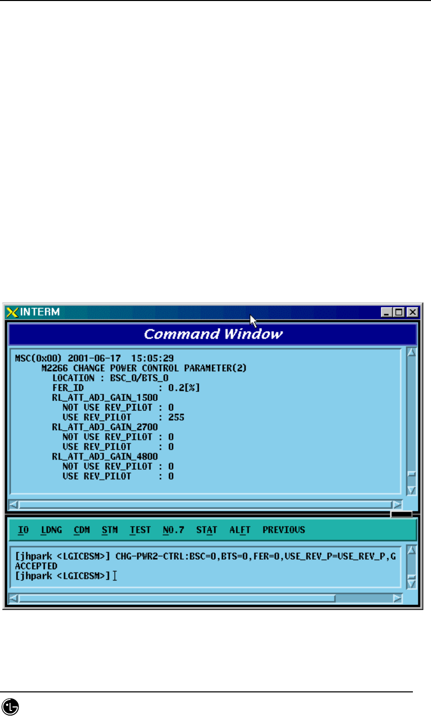
4.3.5.19. POWER CONTROL Parameter Information (2) Change
To change POWER CONTROL Parameter information (2), click CDM-
>Change_Parameter_ Information_2-> CHG-PWR2-CTRL on the Command Window in
order. Input the value to be changed in each field as shown below.
• Command CHG-PWR2-CTRL :BSC=a ,BTS=b ,FER=c ,USE_REV_P=d
[,GAIN_1500=e]
[,GAIN_2700=f] [,GAIN_4800=g] [,GAIN_9600=h] [,GAIN_1800=i]
[,GAIN_3600=j] [,GAIN_7200=k] [,GAIN_14400=l]
[,NORM_9600_5MS=m];
• Input CHG-PWR2-CTRL :BSC=0 ,BTS=0 ,FER=c ,USE_REV_P=USE_REV_P,
GAIN_1500=255;
• Output
Fig. 4.3-119 POWER CONTROL Parameter Information (2) Change
STAREX-IS BSM Manual
Page:312(877)
Issue:1.
0
SMD-011-PMA210
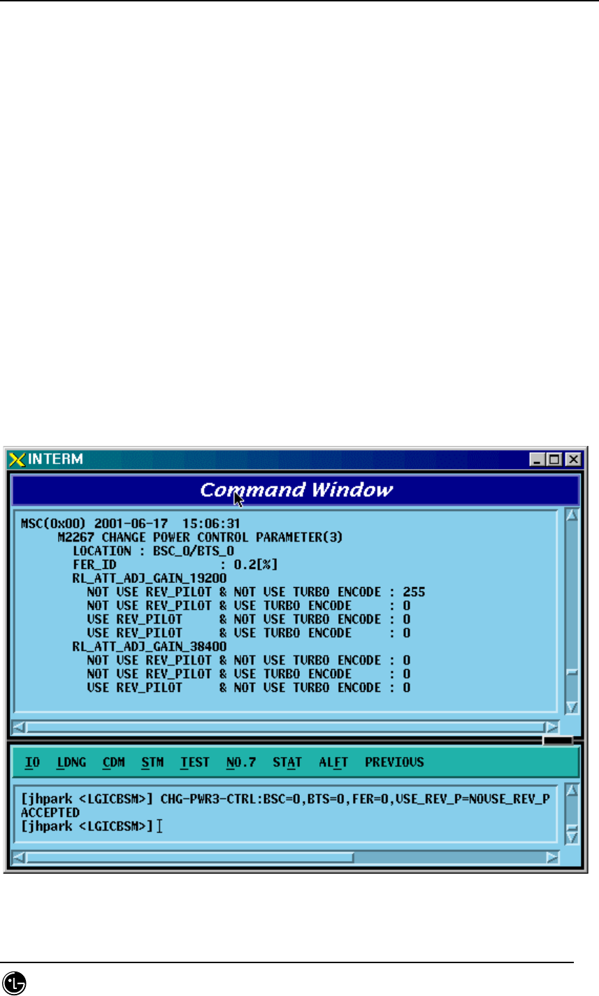
4.3.5.20. POWER CONTROL Parameter Information (3) Change
To change POWER CONTROL Parameter information (3), click CDM-
>Change_Parameter_ Information_2-> CHG-PWR3-CTRL on the Command Window in
order. Input the value to be changed in each field as shown below.
• Command CHG-PWR3-
CTRL :BSC=a ,BTS=b ,FER=c ,USE_REV_P=d ,USE_TUB_ENC=e
[,GAIN_19200=f] [,GAIN_38400=g] [,GAIN_76800=h] [,GAIN_153600=i]
[,GAIN_307200=j] [,GAIN_614400=k] [,GAIN_28800=l]
[,GAIN_57600=m] [,GAIN_115200=n] [,GAIN_230400=o]
[,GAIN_460800=p] [,GAIN_1036800=q];
• Input CHG-PWR3-CTRL :BSC=0 ,BTS=0 ,FER=0 ,USE_REV_P=NOUSE_REV_P ,
USE_TUB_ENC=NOUSE_TUB_ENC,GAIN_19200=255;
• Output
Fig. 4.3-120 POWER CONTROL Parameter Information (3) Change
STAREX-IS BSM Manual
Page:313(877)
Issue:1.
0
SMD-011-PMA210
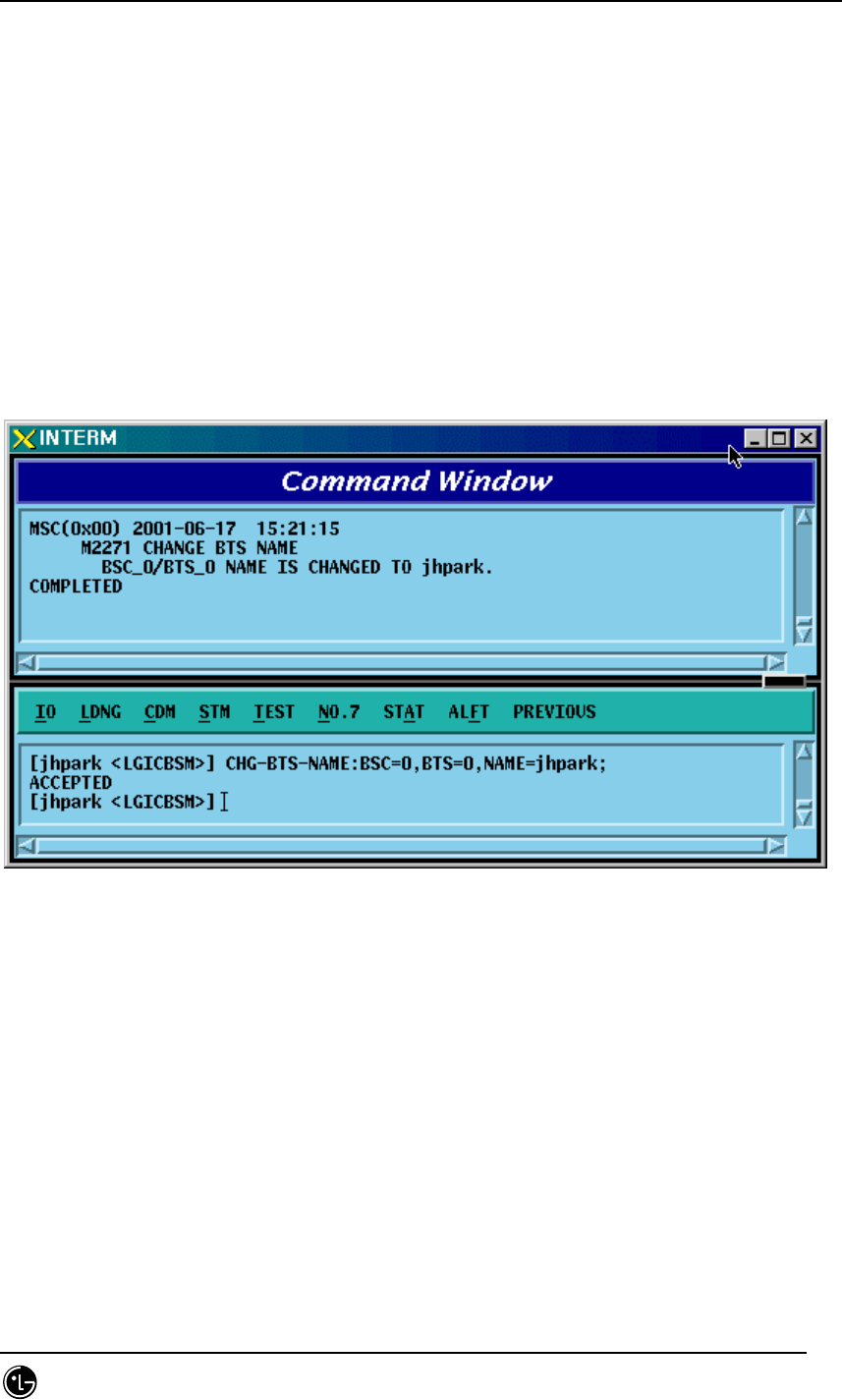
4.3.5.21. BTS Name Change
To change BTS name, click CDM->Change_Parameter_ Information_2-> CHG-BTS-
NAME on the Command Window in order. Input the value to be changed in each field
as shown below.
• Command CHG-BTS-NAME :BSC=a ,BTS=b ,NAME=c;
• Input CHG-BTS-NAME :BSC=0 ,BTS=0 ,NAME=jhpark;
• Output
Fig. 4.3-121 BTS Name Change
STAREX-IS BSM Manual
Page:314(877)
Issue:1.
0
SMD-011-PMA210
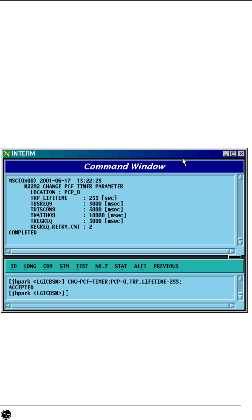
4.3.5.22. PCF TIMER Change
To change PCF TIMER, click CDM->Change_Parameter_ Information_2-> CHG-PCF-
TIMER on the Command Window in order. Input the value to be changed in each field
as shown below.
• Command CHG-PCF-TIMER :PCP=a [,TRP_LIFETIME=b] [,TBSREQ9=c]
[,TDISCON9=d]
[,TWAITHO9=e] [,TREGREQ=f] [,RRQ_RETRY_CNT=g];
• Input CHG-PCF-TIMER :PCP=0,TRP_LIFETIME=255;
• Output
Fig. 4.3-122 PCF TIMER Change
STAREX-IS BSM Manual
Page:315(877)
Issue:1.
0
SMD-011-PMA210
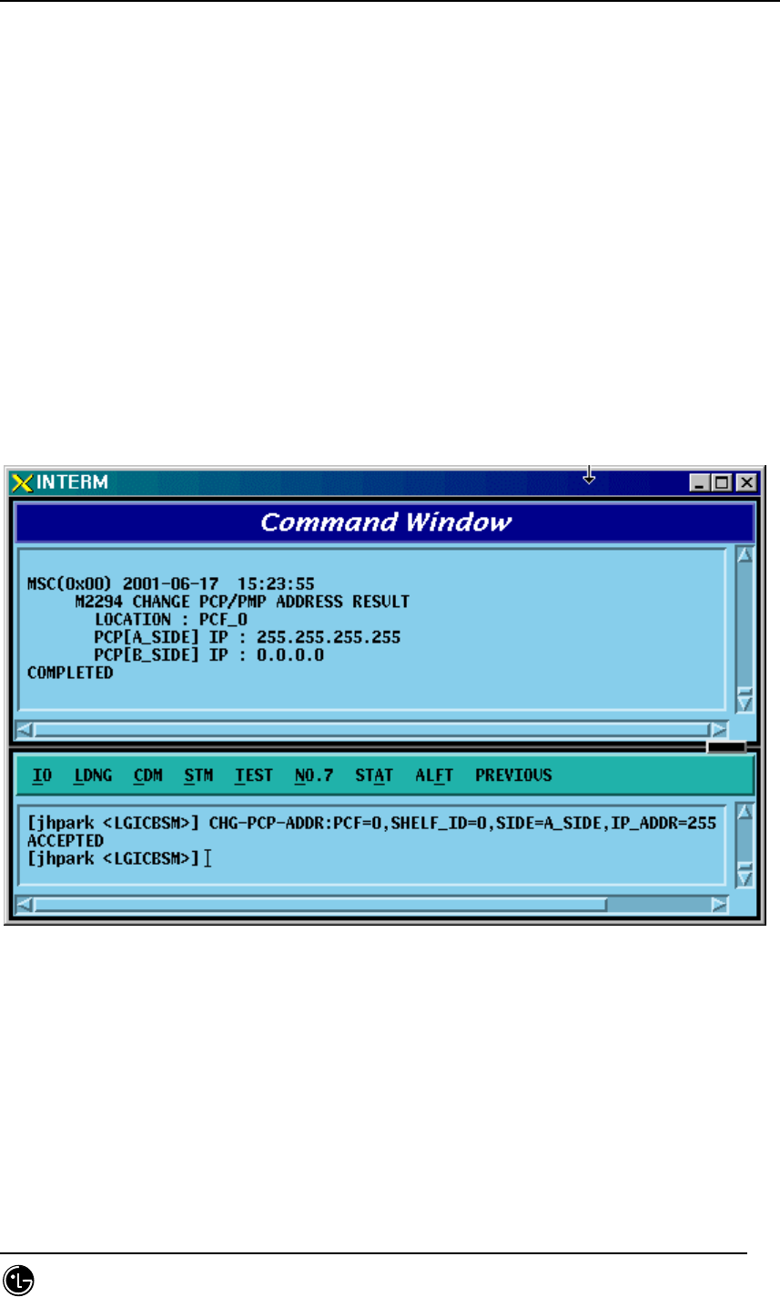
4.3.5.23. PCP/PMP ADDRESS Change
To change PCP/PMP ADDRESS, click CDM->Change_Parameter_ Information_2->
CHG-PCP-ADDR on the Command Window in order. Input the value to be changed in
each field as shown below.
• Command CHG-PCP-ADDR :PCF=a ,SHELF_ID=b ,SIDE=c ,IP_ADDR=d;
• Input CHG-PCP-ADDR :PCF=0 ,SHELF_ID=0 ,SIDE=A_SIDE ,
IP_ADDR=255.255.255.255;
• Output
Fig. 4.3-123 PCP/PMP ADDRESS Change
STAREX-IS BSM Manual
Page:316(877)
Issue:1.
0
SMD-011-PMA210
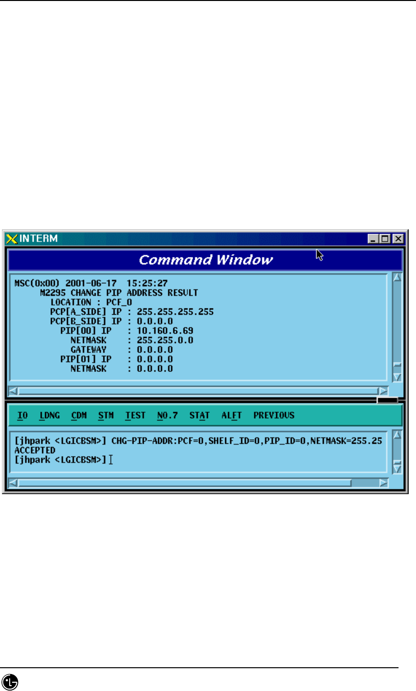
4.3.5.24. PIP ADDRESS Change
To change PIP ADDRESS, click CDM->Change_Parameter_ Information_2-> CHG-
PIP-ADDR on the Command Window in order. Input the value to be changed in each
field as shown below.
• Command CHG-PIP-ADDR :PCF=a ,SHELF_ID=b ,PIP_ID=c [,IP_ADDR=d]
[,NETMASK=e]
• Input CHG-PIP-ADDR :PCF=0 ,SHELF_ID=0 ,PIP_ID=0, NETMASK=255.255.0.0;
• Output
Fig. 4.3-124 PIP ADDRESS Change
STAREX-IS BSM Manual
Page:317(877)
Issue:1.
0
SMD-011-PMA210
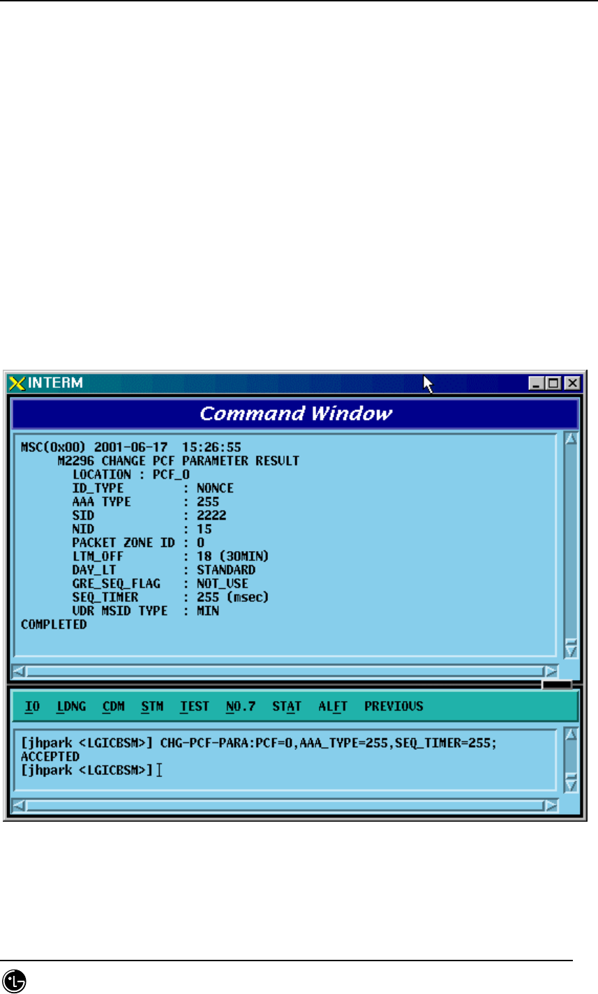
4.3.5.25. PCF PARAMETER Change
To change PCF PARAMETER, click CDM->Change_Parameter_ Information_2-> CHG-
PCF-PARA on the Command Window in order. Input the value to be changed in each
field as shown below.
• Command CHG-PCF-PARA :PCF=a [,AAA_TYPE=b] [,SID=c] [,NID=d]
[,LTM_OFF=e]
[,DAY_LT=f] [,PKZN_ID=g] [,ID_TYPE=h] [,GRE_SEQ=i] [,SEQ_TIMER=j]
[,MSID_TYPE=k];
• Input CHG-PCF-PARA :PCF=0,AAA_TYPE=255,SEQ_TIMER=255;
• Output
Fig. 4.3-125 PCF PARAMETER Change
STAREX-IS BSM Manual
Page:318(877)
Issue:1.
0
SMD-011-PMA210
4.3.6. Network Parameter Information Change
(Change_Parameter_Info_3)
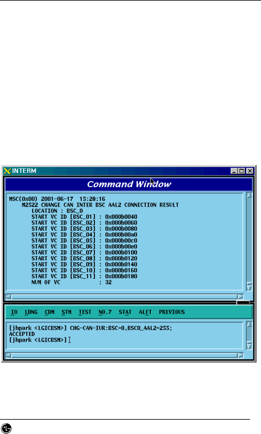
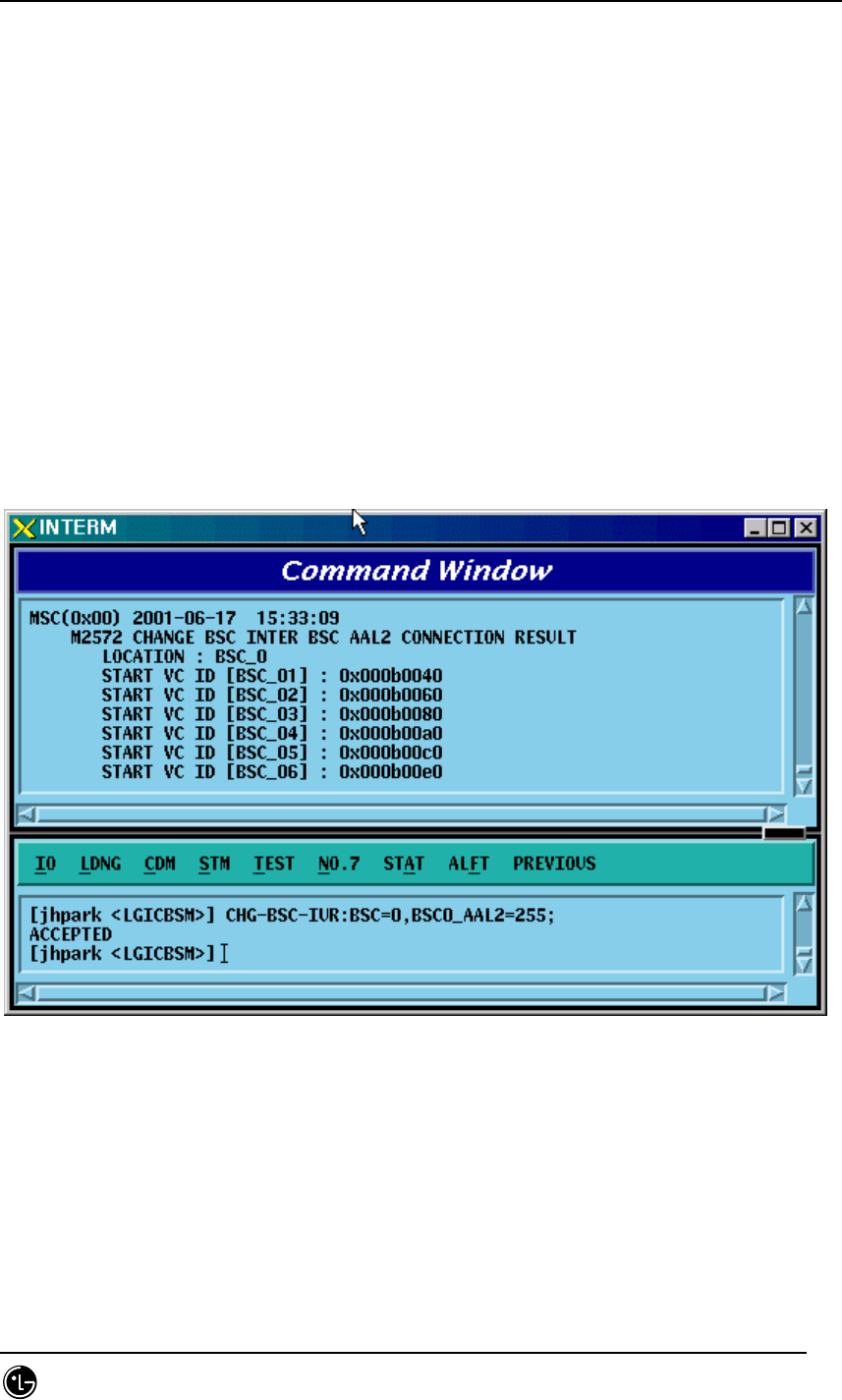
4.3.6.1. CAN INTER BSC AAL2 Setting Information Change
• Command CHG-CAN-IUR: BSC=a, [BSC0_AAL2=b], [BSC1_AAL2=c],
[BSC2_AAL2=d], [BSC3_AAL2=e], [BSC4_AAL2=f],
[BSC5_AAL2=g], [BSC6_AAL2=h], [BSC7_AAL2=i],
[BSC8_AAL2=j],[BSC9_AAL2=k],[BSC10_AAL2=l],
[BSC11_AAL2=m], [NO_AAL2_VC=n];
• Input CHG-CAN-IUR: BSC=0, BSC0_AAL2=255
• Output
STAREX-IS BSM Manual
Page:319(877)
Issue:1.
0
SMD-011-PMA210
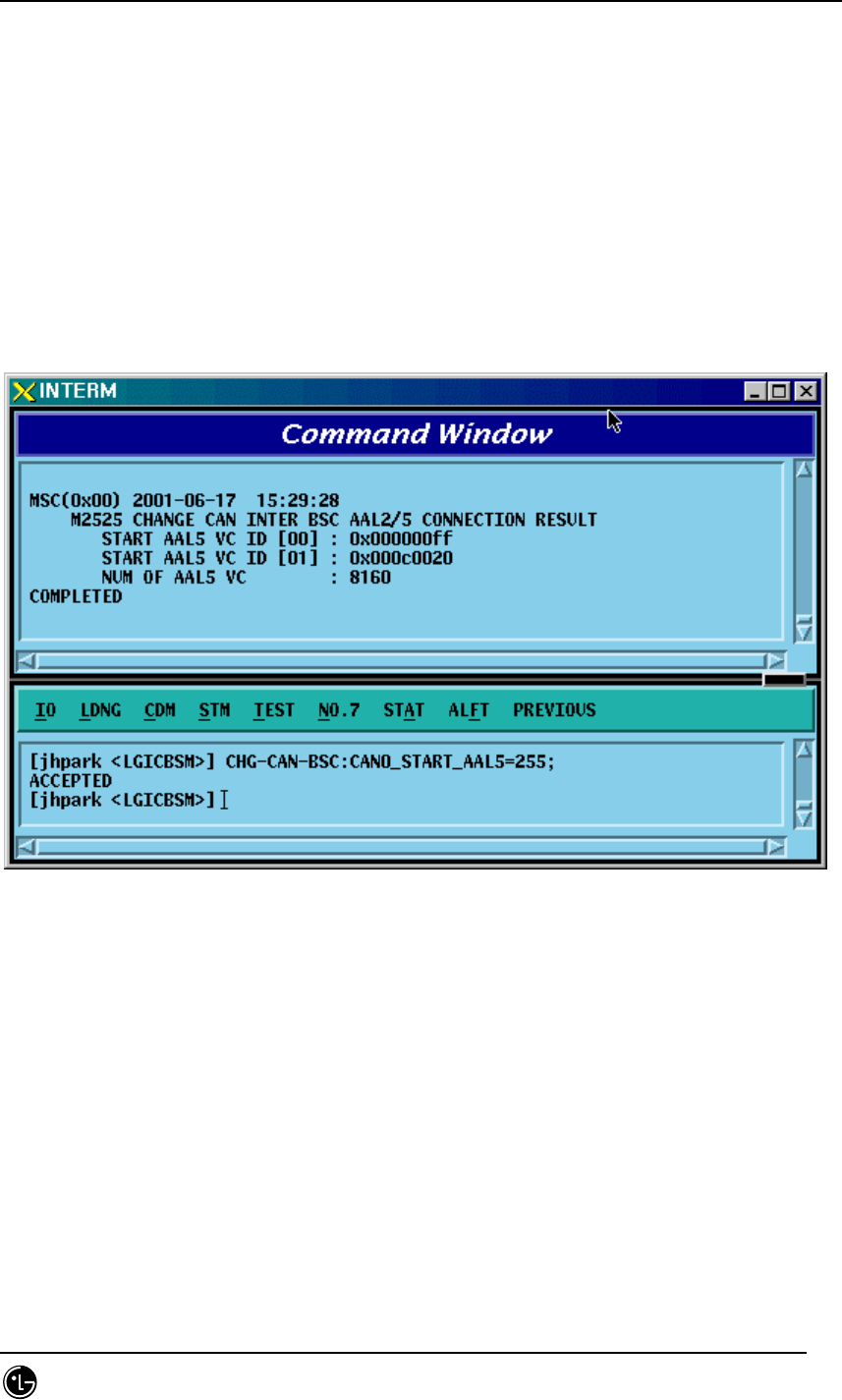
4.3.6.2. CAN INTER BSC AAL5 Setting Information Change
• Command CHG-CAN-BSC: [CAN0_START_AAL5=a],
[CAN1_START_AAL5=b], [NO_AAL5_VC=0~],
a ,b: 0~0xffffff
c: 0~
• Input CHG-CAN-BSC: CAN0_START_AAL5=255
• Output
STAREX-IS BSM Manual
Page:320(877)
Issue:1.
0
SMD-011-PMA210
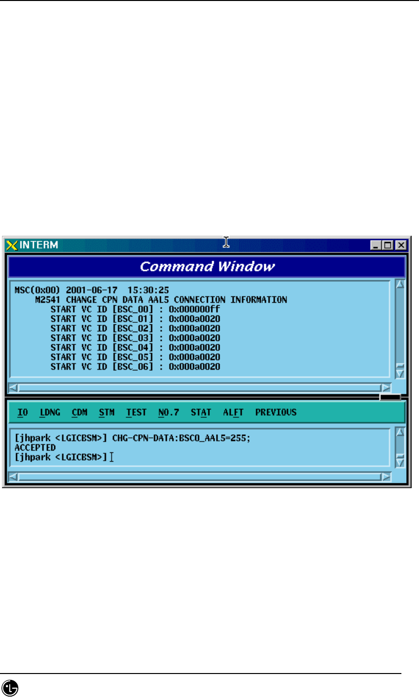
4.3.6.3. CPN INTER DATA AAL5 Setting Information Change
• Command CHG-CPN-DATA: [BSC0_AAL5=a], [BSC1_AAL5=b], [BSC2_AAL5=c],
[BSC3_AAL5=d], [BSC4_AAL5=e], [BSC5_AAL5=f],
[BSC6_AAL5=g], [BSC7_AAL5=h], [BSC8_AAL5=i],
[BSC9_AAL5=j], [BSC10_AAL5=k], [BSC11_AAL5=l],
[NO_AAL5_VC=m];
a ~n: BSC AAL5 (32~0xffffff)
m: 0~32
• Input CHG-CPN-DATA: BSC0_AAL5=255;
• Output
STAREX-IS BSM Manual
Page:321(877)
Issue:1.
0
SMD-011-PMA210
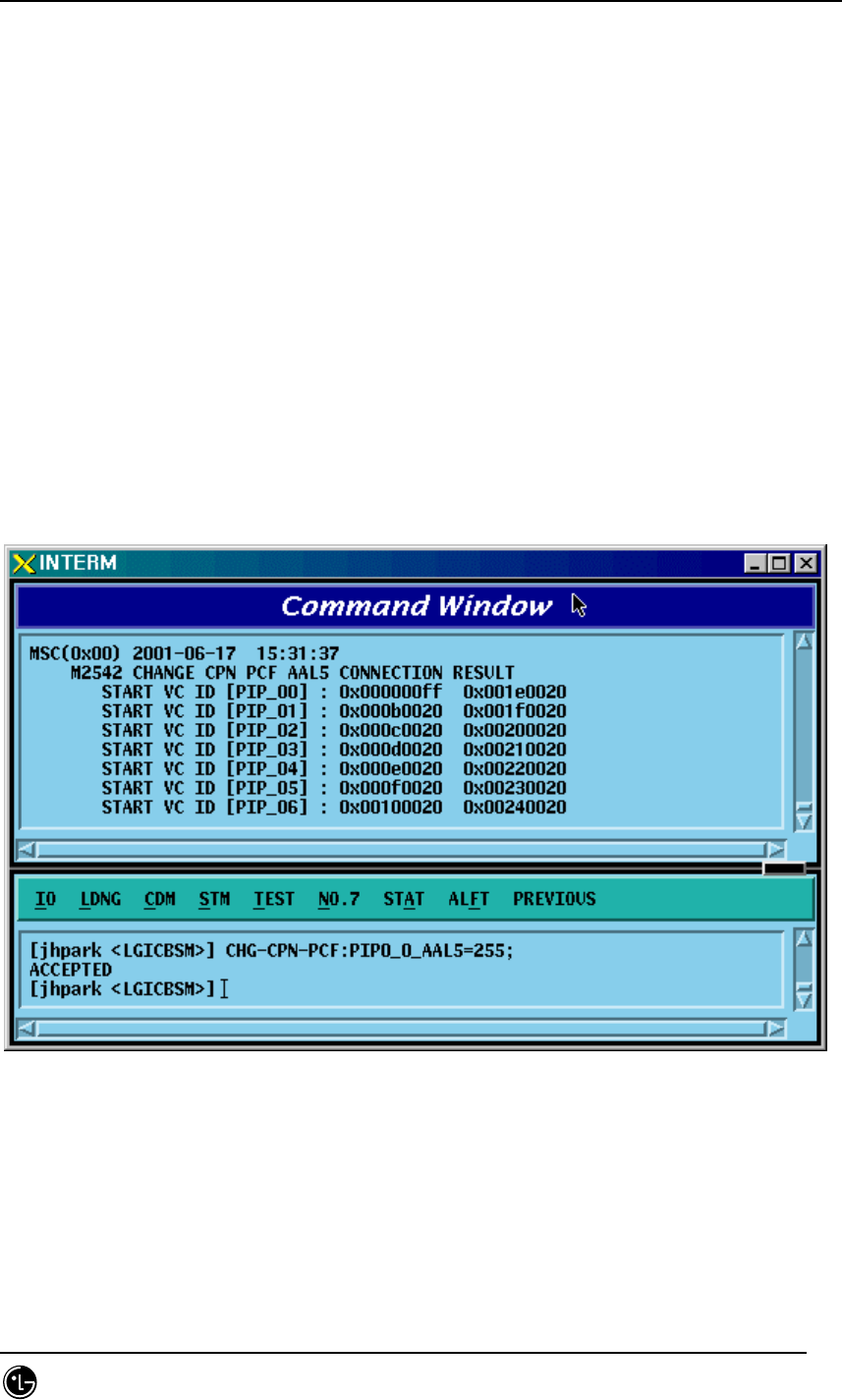
4.3.6.4. CPN INTER PCF AAL5 Setting Information Change
• Command CHG-CPN-PCF: [PIP0_0_AAL5=a], [PIP0_1_AAL5=b], [PIP1_0_AAL5=c],
[PIP1_1_AAL5=d], [PIP2_0_AAL5=e], [PIP2_1_AAL5=f],
[PIP3_0_AAL5=g], [PIP3_1_AAL5=h], [PIP4_0_AAL5=i],
[PIP4_1_AAL5=j], [PIP5_0_AAL5=k], [PIP5_1_AAL5=l],
[PIP6_0_AAL5=m], [PIP6_1_AAL5=n], [PIP7_0_AAL5=o],
[PIP7_1_AAL5=p], [PIP8_0_AAL5=q], [PIP8_1_AAL5=r],
[PIP9_0_AAL5=s], [PIP9_1_AAL5=t], [PIP10_0_AAL5=u],
[PIP10_1_AAL5=v], [NO_AAL5_VC=w]
a~v: PIP AAL5 (32~0xffffff)
w: 0~480
• Input CHG-CPN-PCF: PIP0_0_AAL5=255 ;
• Output
STAREX-IS BSM Manual
Page:322(877)
Issue:1.
0
SMD-011-PMA210
4.3.6.5. BSC INTER BSC AAL2 Setting Information Change
• Command CHG-BSC-IUR: BSC=a, [BSC0_AAL2=b], [BSC1_AAL2=c],
[BSC2_AAL2=d],
[BSC3_AAL2=e], [BSC4_AAL2=f], [BSC5_AAL2=g],
[BSC6_AAL2=h], [BSC7_AAL2=i], [BSC8_AAL2=j],
[BSC9_AAL2=k], [BSC10_AAL2=l], [BSC11_AAL2=m],
[NO_AAL2_VC=n];
a : BSC Number(0~11)
b~m: BSC AAL2 (0~0xffffff)
n: 0~
• Input CHG-BSC-IUR: BSC=0, BSC0_AAL2=255;
• Output
STAREX-IS BSM Manual
Page:323(877)
Issue:1.
0
SMD-011-PMA210
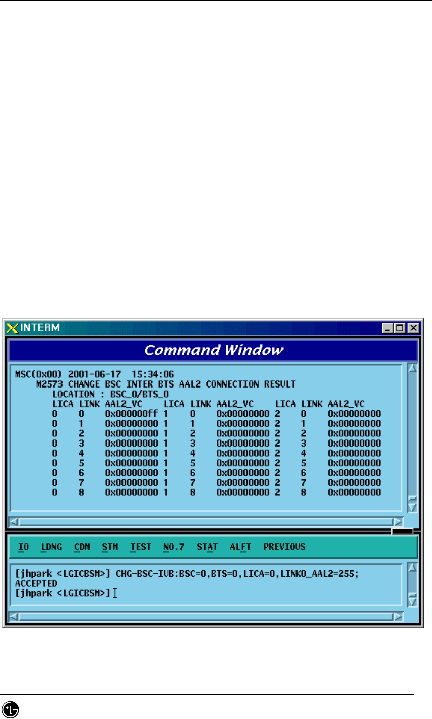
4.3.6.6. BSC INTER BTSC AAL2 Setting Information Change
• Command CHG-BSC-IUB: BSC=a, BTS=b, LICA=c, LINK=d,
[LINK0_AAL2=e], [LINK1_AAL2=f], [LINK2_AAL2=g],
[LINK3_AAL2=h], [LINK4_AAL2=i], [LINK5_AAL2=j],
[LINK6_AAL2=k], [LINK7_AAL2=l], [LINK8_AAL2=m],
[LINK9_AAL2=n], [LINK10_AAL2=o], [LINK11_AAL2=p],
[LINK12_AAL2=q], [LINK13_AAL2=r], [LINK14_AAL2=s],
[LINK15_AAL2=t]
a : BSC Number(0~11)
b : BTS Number(0~47)
c : LICA Number(0~2)
d : LINK Number(0~15)
e~t: 0~0xffffff
• Input CHG-BSC-IUB: BSC=0, BTS=0, LICA=0, LINK0_AAL2=255;
• Output
STAREX-IS BSM Manual
Page:324(877)
Issue:1.
0
SMD-011-PMA210
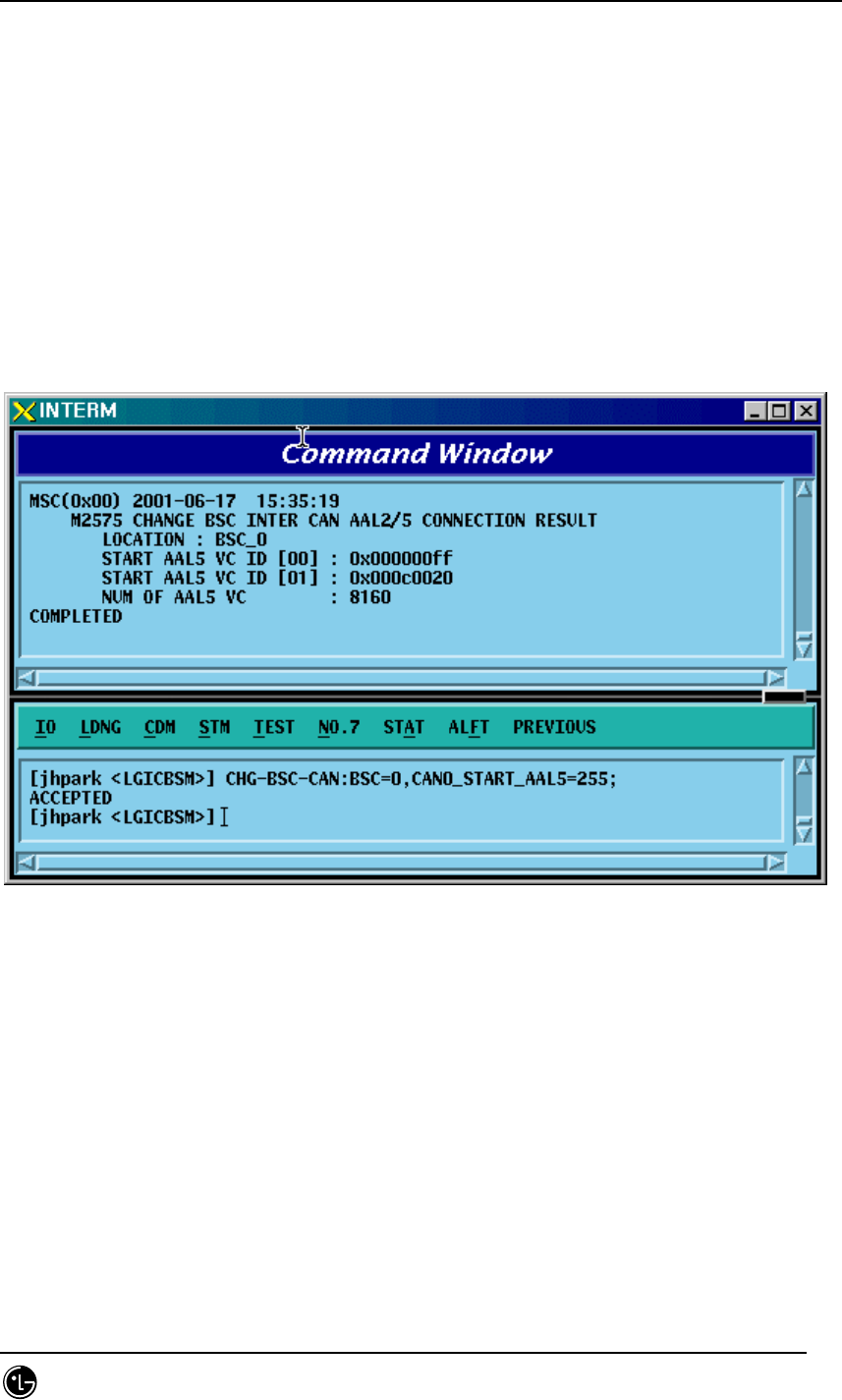
4.3.6.7. BSC INTER CAN AAL2/5 Setting Information Change
• Command CHG-BSC-CAN: BSC=a, [CAN0_START_AAL5=b],
[CAN1_START_AAL5=c], [NO_AAL5_VC=d]
a: BSC Number(0~11)
b,c: 32~0xffffff
d: 0~8160
• Input CHG-BSC-CAN: BSC=0, CAN0_START_AAL5=255;
• Output
STAREX-IS BSM Manual
Page:325(877)
Issue:1.
0
SMD-011-PMA210
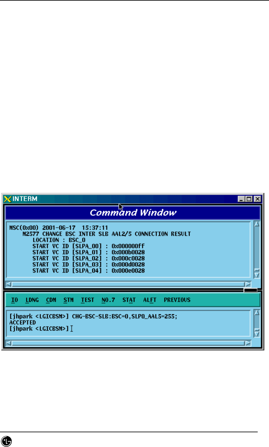
4.3.6.8. BSC INTER SLB AAL5 Setting Information
• Command CHG-BSC-SLB: BSC=a, [SLP0_AAL5=b], [SLP1_AAL5=c],
[SLP2_AAL5=d],
[SLP3_AAL5=e], [SLP4_AAL5=f], [SLP5_AAL5=g],
[SLP6_AAL5=h], [SLP7_AAL5=i], [SLP8_AAL5=j],
[SLP9_AAL5=k], [SLP10_AAL5=l], [SLP11_AAL5=m],
[SLP12_AAL5=n], [SLP13_AAL5=o], [SLP14_AAL5=p],
[SLP15_AAL5=q], [SLP16_AAL5=r], [SLP17_AAL5=s],
[NO_AAL5_VC=t]
a: BSC Number(0~11)
b~s: 40~0xffffff
t: 0~984
• Input CHG-BSC-SLB: BSC=0, SLP0_AAL5=255;
• Output
STAREX-IS BSM Manual
Page:326(877)
Issue:1.
0
SMD-011-PMA210
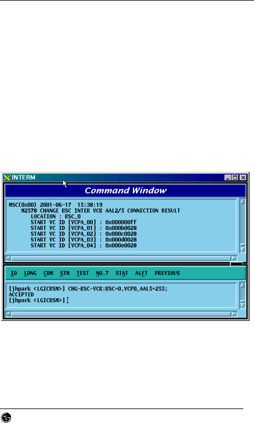
4.3.6.9. BSC INTER VCB AAL5 Setting Information Change
• Command CHG-BSC-VCB: BSC=a,
[VCP0_AAL5=b], [VCP1_AAL5=c], [VCP2_AAL5=d],
[VCP3_AAL5=e], [VCP4_AAL5=f], [VCP5_AAL5=g],
[VCP6_AAL5=h], [VCP7_AAL5=i], [VCP8_AAL5=j],
[VCP9_AAL5=k], [VCP10_AAL5=l], [VCP11_AAL5=m],
[VCP12_AAL5=n], [VCP13_AAL5=o], [VCP14_AAL5=p],
[VCP15_AAL5=q], [NO_AAL5_VC=r]
a: BSC Number(0~11)
b~q: 40~0xffffff
r: 0~88
• Input CHG-BSC-VCB: BSC=0, VCP0_AAL5=255;
• Output
STAREX-IS BSM Manual
Page:327(877)
Issue:1.
0
SMD-011-PMA210
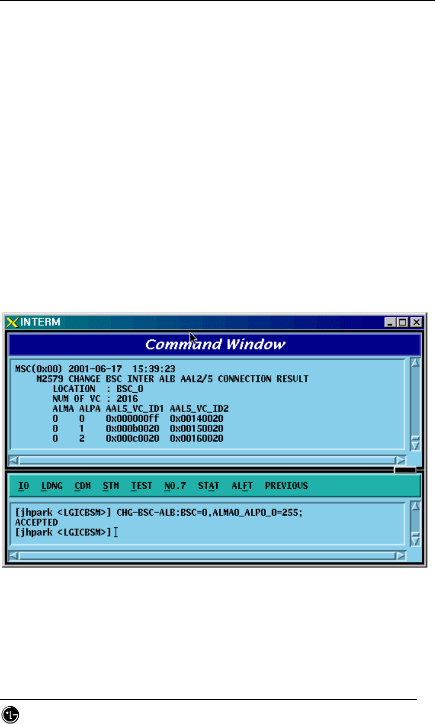
4.3.6.10. BSC INTER ALB AAL5 Setting Information Change
• Command CHG-BSC-ALB: BSC=a,
[ALMA0_ALP0_0=b], [ALMA0_ALP0_1=c], [ALMA0_ALP1_0=d],
[ALMA0_ALP1_1=e], [ALMA0_ALP2_0=f], [ALMA0_ALP2_1=g],
[ALMA0_ALP3_0=h], [ALMA0_ALP3_1=i], [ALMA0_ALP4_0=j],
[ALMA0_ALP4_1=k], [ALMA1_ALP0_0=l], [ALMA1_ALP0_1=m],
[ALMA1_ALP1_0=n], [ALMA1_ALP1_1=o], [ALMA1_ALP2_0=p],
[ALMA1_ALP2_1=q], [ALMA1_ALP3_0=r], [ALMA1_ALP3_1=s],
[ALMA1_ALP4_0=t], [ALMA1_ALP4_1=u], [NO_AAL5_VC=v]
a: BSC Number(0~11)
b~u: 32~0xffffff
v: 0~2016
• Input CHG-BSC-ALB: BSC=0, ALMA0_ALP0_0=255;
• Output
STAREX-IS BSM Manual
Page:328(877)
Issue:1.
0
SMD-011-PMA210
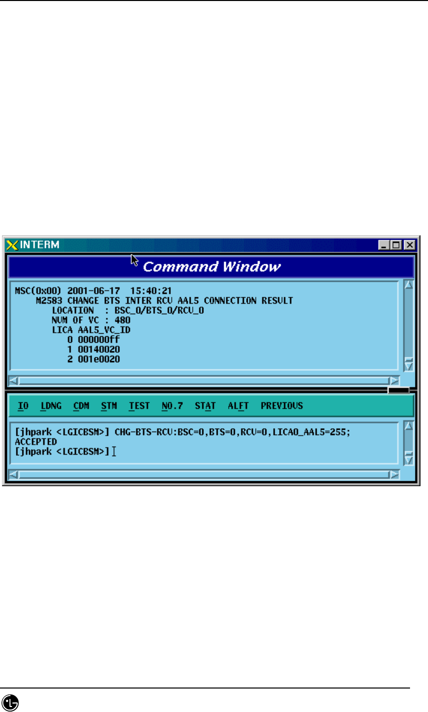
4.3.6.11. BTS INTER RCU AAL5 Setting Information Change
• Command CHG-BTS-RCU: BSC=a, BTS=b, RCU=c,
[LICA0_AAL5=d], [LICA1_AAL5=e], [LICA2_AAL5=f],
[LICA0_NO_VC=g], [LICA1_NO_VC=h], [LICA2_NO_VC=i]
a: BSC Number(0~11)
b:BTS Number(0~47)
c: RCU Number(0~9)
d~i: 0~
• Input CHG-BTS-RCU: BSC=0,BTS=0,RCU=0, LICA0_AAL5=255;
• Output

STAREX-IS BSM Manual
Page:329(877)
Issue:1.
0
SMD-011-PMA210
4.3.7. Configuration Information
Display(Display_Configuration_Data)
This section describes the comands that are used to inquire the configuration
information which is related to processors, devices, and overhead channels which are
currently used in BTS and BSC.
Table 4.3-3 Configuration Information Display
CRN MMC Description
2101 DIS-BSS-CONF BSS configuration information
verification
2103 DIS-SMP-CONF SMP configuration information
verification
2105 DIS-VMP-CONF VMP configuration information
verification
2112 DIS-BTS-CONF BTS configuration information
verification
2115 DIS-CHIP-CONF DBPA CHIP configuration information
verification
2125 DIS-OVHD-CONF OVERHEAD CHANNEL configuration
information verification
2133 DIS-PDSN-CONF PDSN configuration information
verification
STAREX-IS BSM Manual
Page:330(877)
Issue:1.
0
SMD-011-PMA210
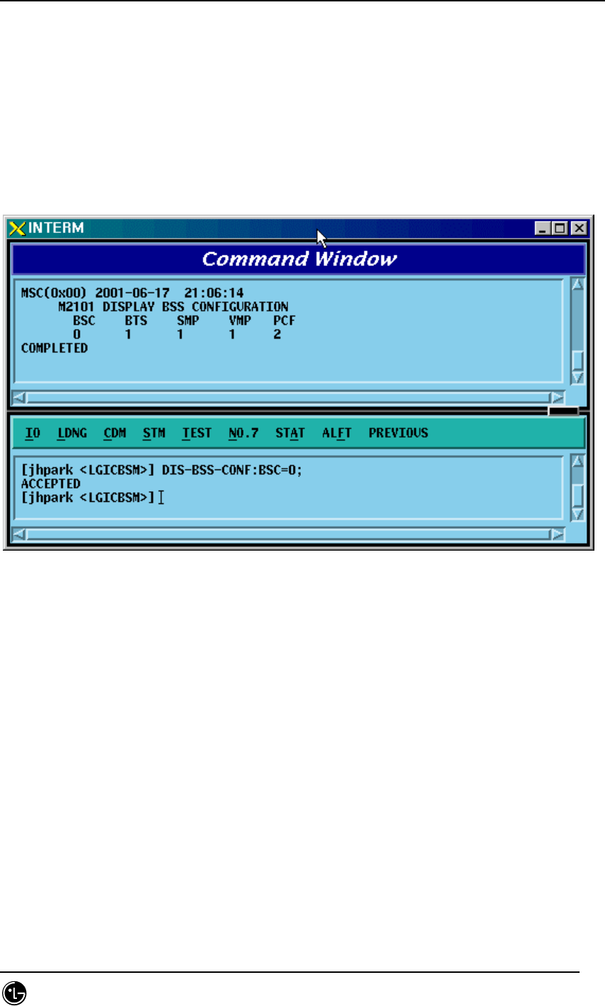
4.3.7.1. BSS Configuration Information Verification
This is a command to check the BTS, Processors and PCF counts in the BSC.
• Command DIS-BSS-CONF: BSC=a;
• Input DIS-BSS-CONF: BSC=0;
• Output
Fig. 4.3-126 BSS Configuration Information Display
STAREX-IS BSM Manual
Page:331(877)
Issue:1.
0
SMD-011-PMA210
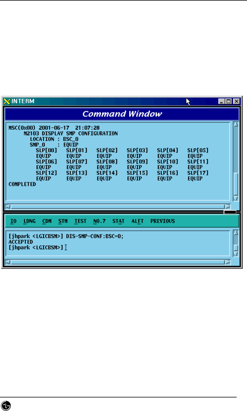
4.3.7.2. SMP Configuration Information Verification
• Command DIS-SMP-CONF: BSC=a;
a: BSC Number(#0~11)
• Input DIS-SMP-CONF: BSC=0;
• Output
Fig. 4.3-127 SMP Configuration Information Display
STAREX-IS BSM Manual
Page:332(877)
Issue:1.
0
SMD-011-PMA210
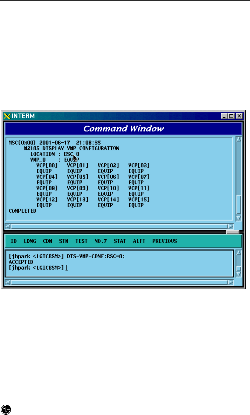
4.3.7.3. VMP Configuration Information Verification
• Command DIS-VMP-CONF: BSC=a;
a: BSC Number(#0~11)
• Input DIS-VMP-CONF: BSC=0;
• Output
Fig. 4.3-128 VMP Configuration Information Display
STAREX-IS BSM Manual
Page:333(877)
Issue:1.
0
SMD-011-PMA210
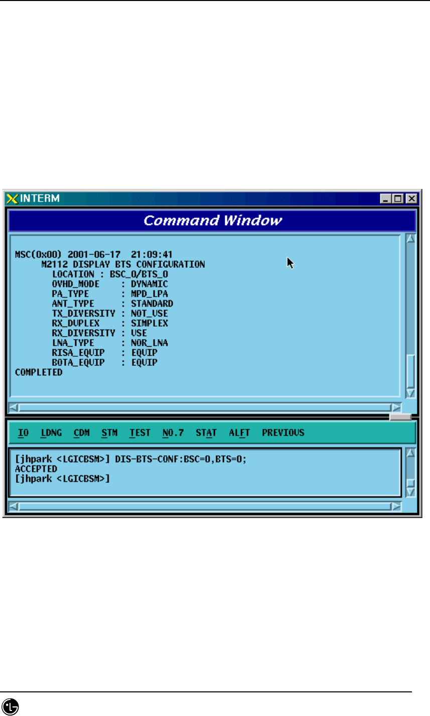
4.3.7.4. BTS Configuration Information Verification
• Command DIS-BTS-CONF: BSC=a, BTS=b;
a: BSC Number(#0~11)
b: BTS Number(#0~47)
• Input DIS-BTS-CONF: BSC=0, BTS=0;
• Output
Fig. 4.3-129 BTS Configuration Information Display
STAREX-IS BSM Manual
Page:334(877)
Issue:1.
0
SMD-011-PMA210
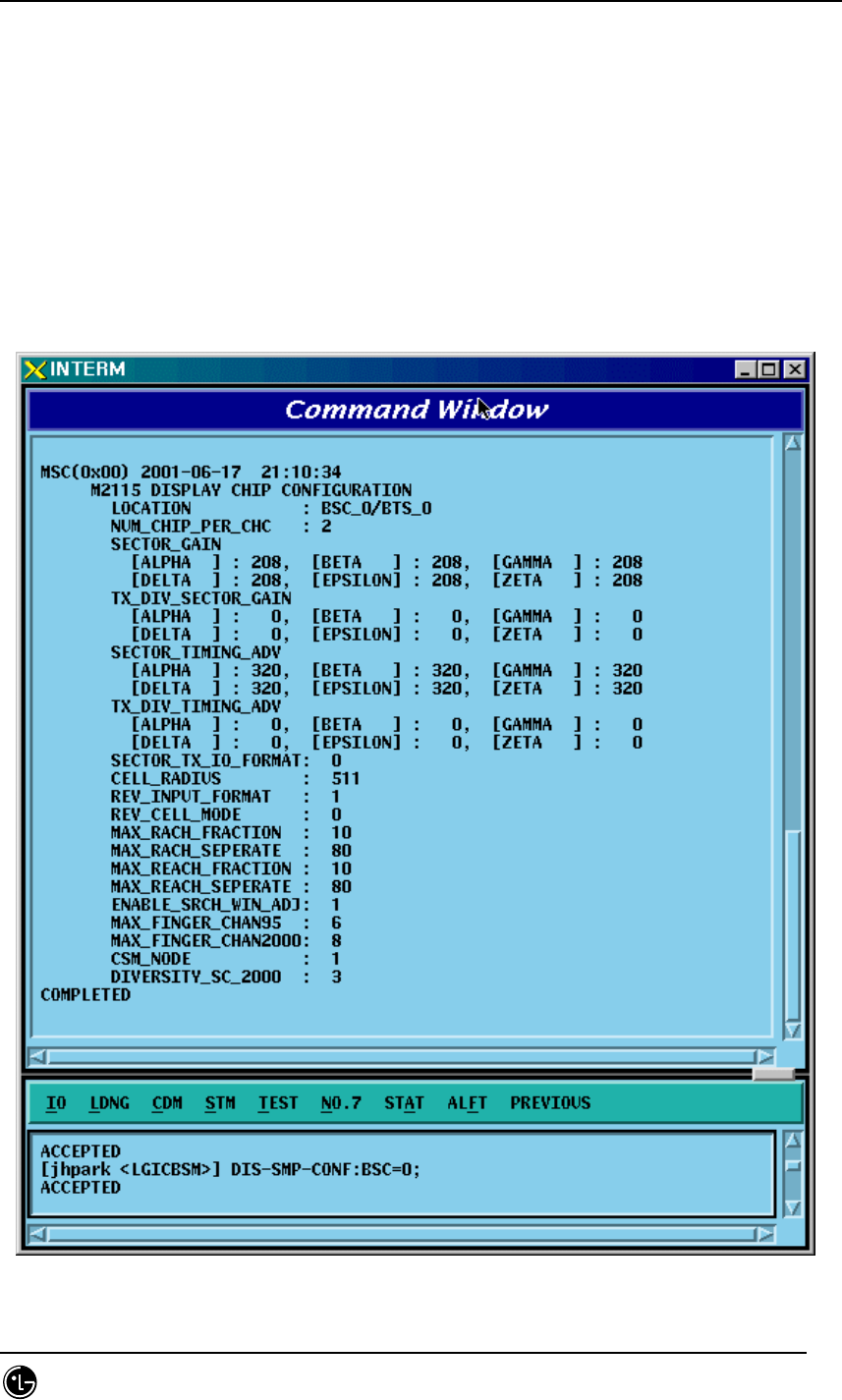
4.3.7.5. DBPA CHIP Configuration Information Verification
• Command DIS-CHIP-CONF: BSC=a, BTS=b;
a: BSC Number(#0~11)
b: BTS Number(#0~47)
• Input DIS-CHIP-CONF: BSC=0, BTS=0;
• Output
Fig. 4.3-130 DBPA CHIP Configuration Information Display
STAREX-IS BSM Manual
Page:335(877)
Issue:1.
0
SMD-011-PMA210
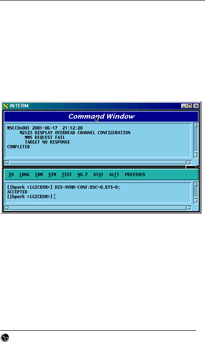
4.3.7.6. OVERHEAD CHANNEL Configuration Information Verification
• Command DIS-OVHD-CONF: BSC=a, BTS=b;
a: BSC Number(#0~11)
b: BTS Number(#0~47)
• Input DIS-OVHD-CONF: BSC=0, BTS=0;
• Output
Fig. 4.3-131 OVHD Channel Configuration Information Display
STAREX-IS BSM Manual
Page:336(877)
Issue:1.
0
SMD-011-PMA210
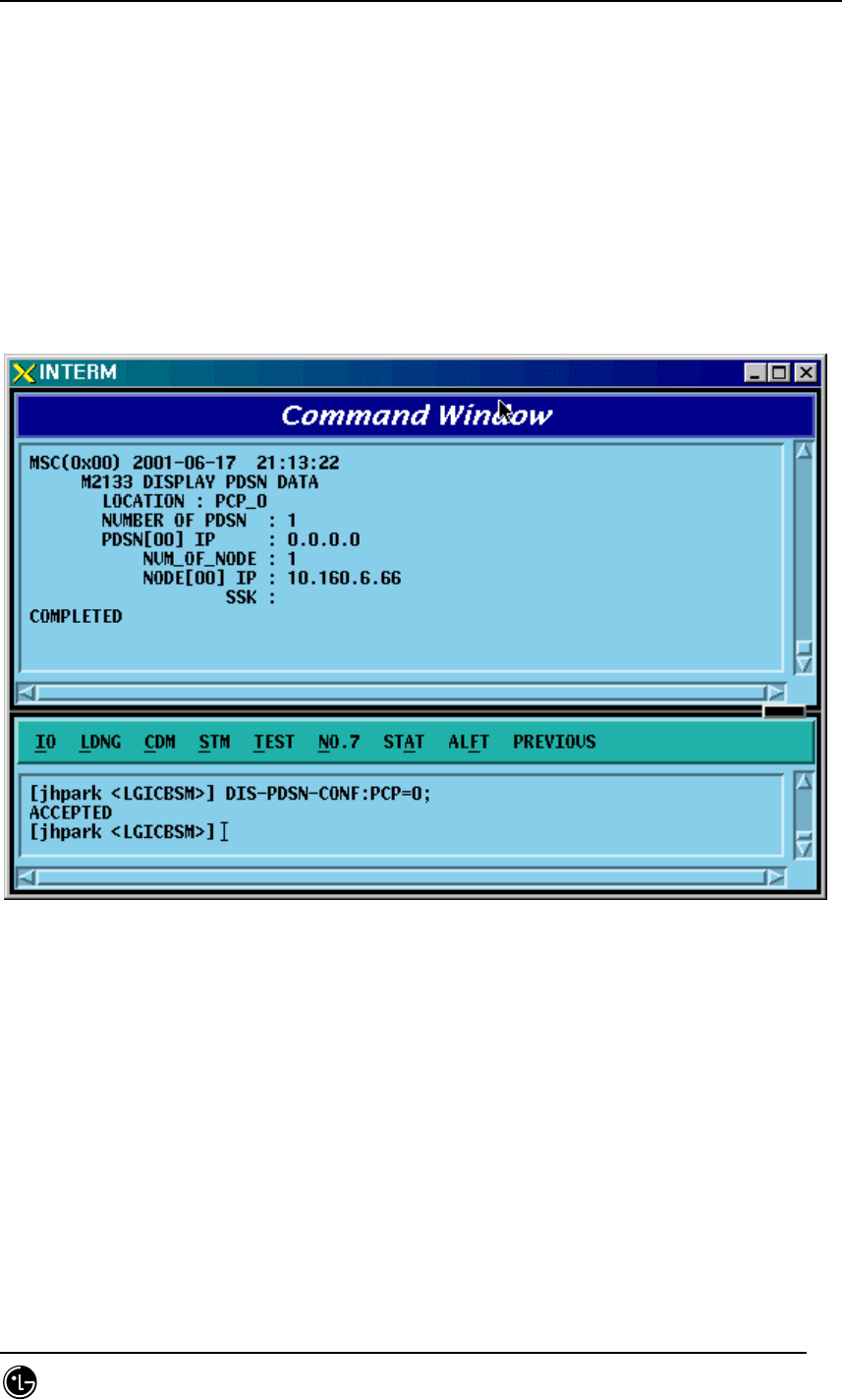
4.3.7.7. PDSN Configuration Information Verification
• Command DIS-PDSN-CONF: PCP=a;
a: PCP Number(#0~2)
• Input DIS-PDSN-CONF: PCP=0;
• Output
Fig. 4.3-132 PDSN Configuration Information Display

STAREX-IS BSM Manual
Page:337(877)
Issue:1.
0
SMD-011-PMA210
4.3.8. Configuration Information Change
(Change_Configuration_Data)
This section describes commands that are used to add or delete BTS and BSC
processors and devices. The configuration information that can be added and deleted
are presented below. For the command that has many parameters to input, input image
on the inpout Widow. This section does not cover details of each parameter.
Table 4.3-4 Configuration Information Change
CRN MMC Description
C2312 CHG-BTS-CONF BTS configuration information change
C2315
CHG-CHIP1-CONF
Channel Card Chip configuration
information(1) change
C2317
CHG-CHIP2-CONF
Channel Card Chip configuration
information(2) change
C2333 ADD-PDSN-CONF PDSN CONFIG addition
C2334 RMV-PDSN-CONF PDSN CONFIG deletion
C2335 CHG-PDSN-CONF PDSN CONFIG change
C2337 ADD-PDSN-NODE PDSN NODE addition
C2338 RMV-PDSN-NODE PDSN NODE deletion
C2339 CHG-PDSN-NODE PDSN NODE change
C2601 MOV-BSC-NODE BSC Node movement
C2602 MOV-PCF-NODE PCF Node movement
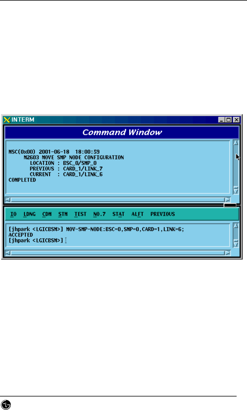
C2603 MOV-SMP-NODE SMP Node movement
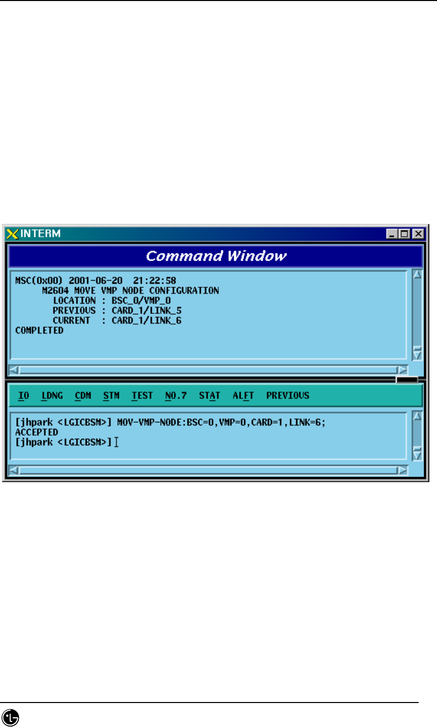
C2604 MOV-VMP-NODE VMP Node movement
C2605 MOV-BTS-ID BTS ID movement
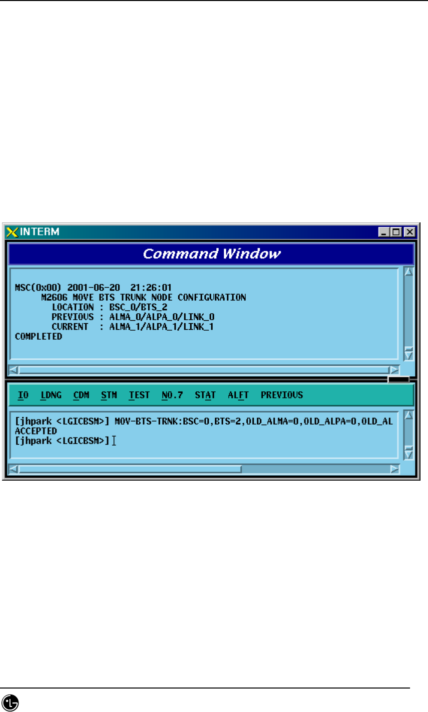
C2606 MOV-BTS-TRNK BTS TRUNK Node movement
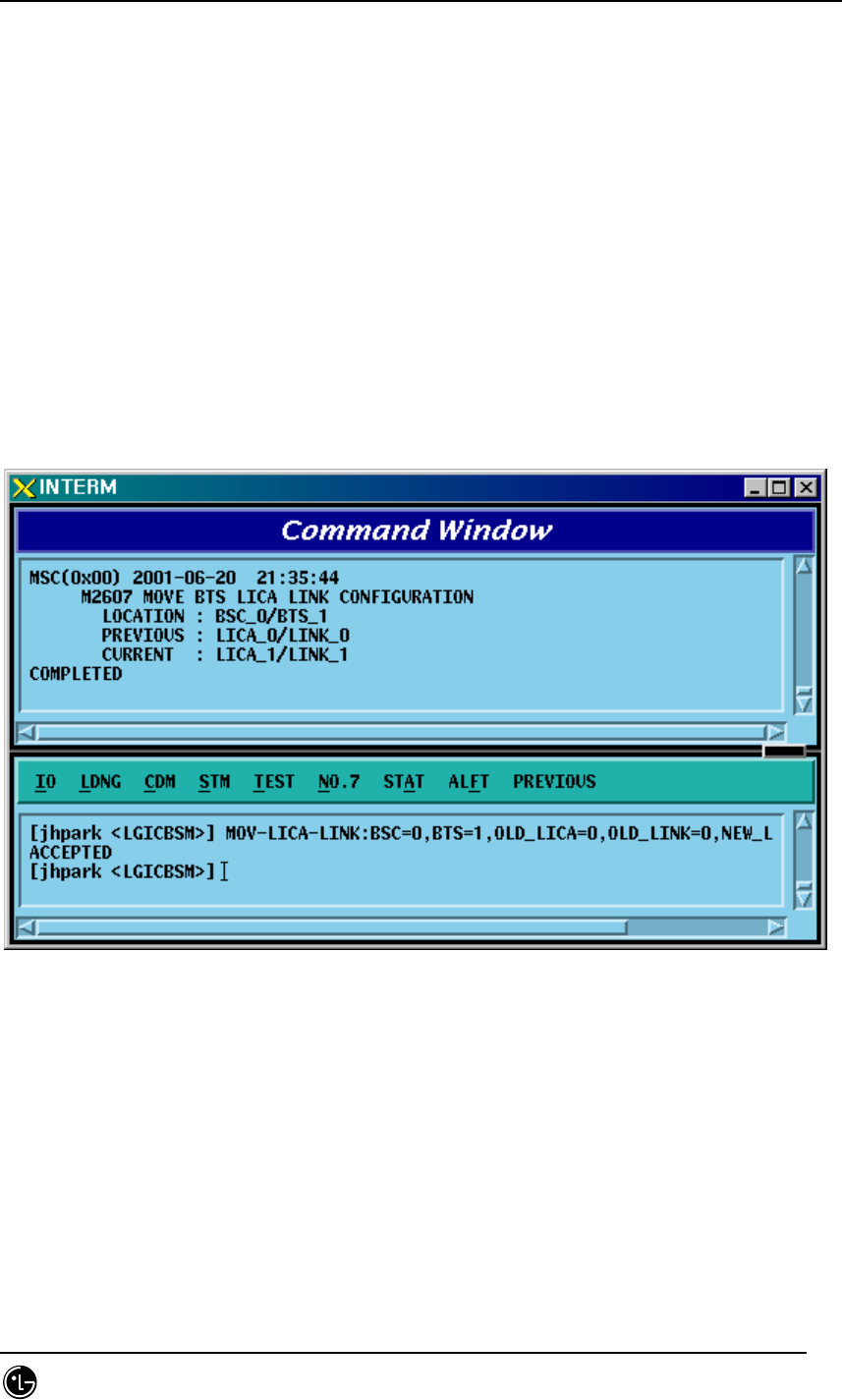
C2607 MOV-LICA-LINK LICA LINK movement
C2610 MOV-OVHD-CONF OVERHEAD CHANNEL configuration
information movement
C2701 ADD-BSC-CONF BSC configuration addition
C2702 RMV-BSC-CONF BSC configuration deletion
C2711 ADD-PCF-CONF PCF configuration addition
C2712 RMV-PCF-CONF PCF configuration deletion

STAREX-IS BSM Manual
Page:338(877)
Issue:1.
0
SMD-011-PMA210
C2721 ADD-SMP-CONF SMP configuration addition
C2722 RMV-SMP-CONF SMP configuration deletion
C2731 ADD-VMP-CONF VMP configuration addition
C2732 RMV-VMP-CONF VMP configuration deletion
C2741 ADD-BTS-CONF BTS configuration addition
C2742 RMV-BTS-CONF BTS configuration deletion
C2751 ADD-SECT-CONF SECTOR configuration addition
C2752 RMV-SECT-CONF SECTOR configuration deletion
C2761 ADD-FA-CONF FA configuration addition
C2762 RMV-FA-CONF FA configuration deletion
C2771 ADD-TRNK-CONF BSC-BTS TRUNK configuration
addition
C2772 RMV-TRNK-CONF BSC-BTS TRUNK configuration
deletion
C2781 ADD-CAN-PVC CAN PVC configuration addition
C2782 RMV-CAN-PVC CAN PVC configuration deletion
C2783 ADD-CPN-PVC CPN PVC configuration addition
C2784 RMV-CPN-PVC CPN PVC configuration deletion
C2785 ADD-BSC-PVC BSC PVC configuration addition
C2786 RMV-BSC-PVC BSC PVC configuration deletion
STAREX-IS BSM Manual
Page:339(877)
Issue:1.
0
SMD-011-PMA210
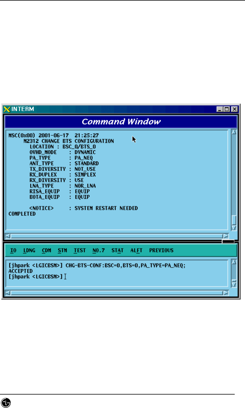
4.3.8.1. BTS Configuration Information Change
• Command CHG-BTS-CONF :BSC=a ,BTS=b [,PA_TYPE=c] [,ANT_TYPE=d]
[,ANT_DUP=e] [,RX_DIV=f] [,LNA_EQP=g] [,RISA_EQP=h] [,BOTA_EQP=i];
• Input CHG-BTS-CONF: BSC=0, BTS=0,PA_TYPE=FA_NEQ;
• Output
Fig. 4.3-133 BTS Configuration Information Change Display

STAREX-IS BSM Manual
Page:340(877)
Issue:1.
0
SMD-011-PMA210
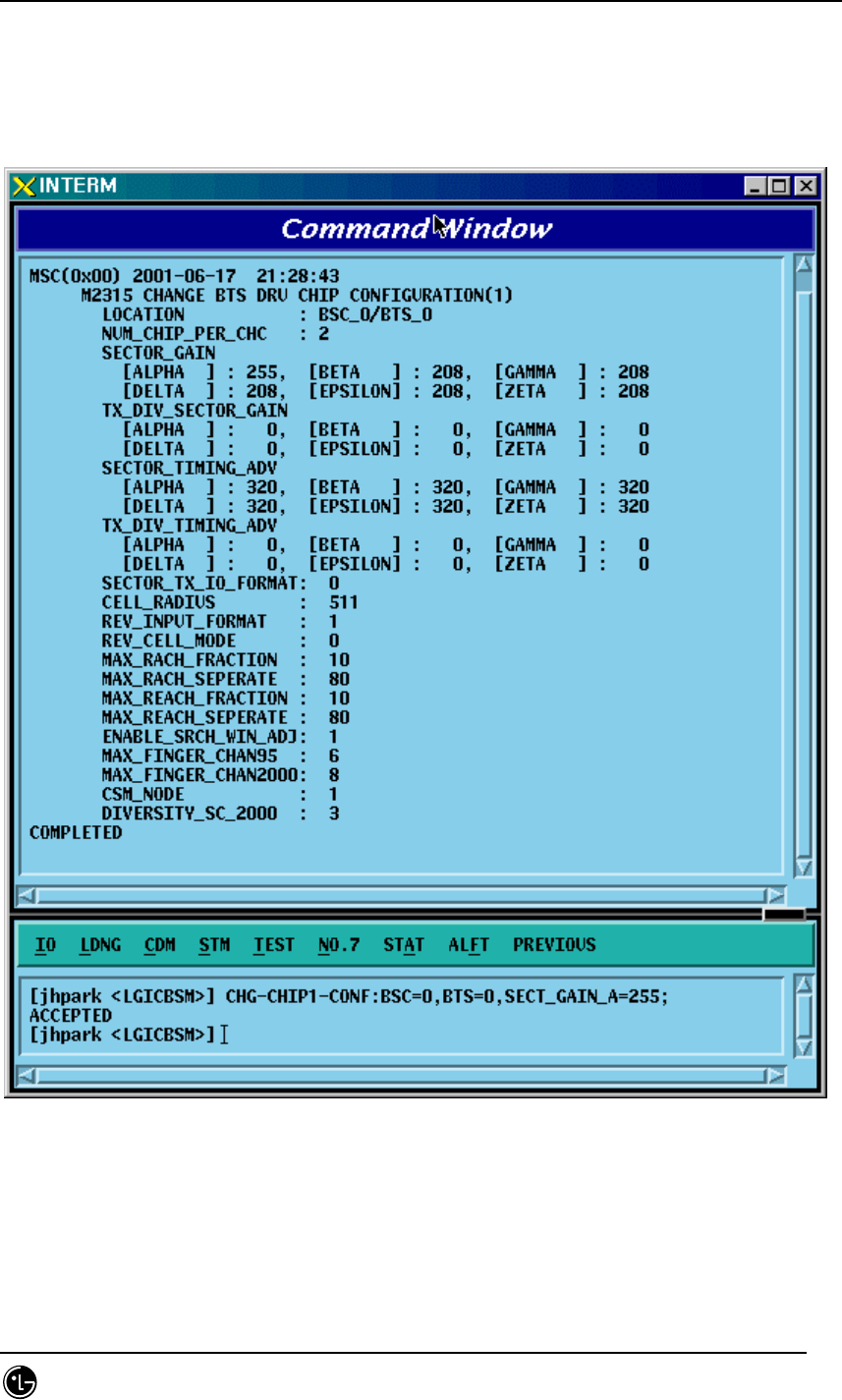
4.3.8.2. Channel Card Chip Configuration Information (1) Change
• Command CHG-CHIP1-CONF :BSC=a ,BTS=b [,SECT_GAIN_A=c]
[,SECT_GAIN_B=d]
[,SECT_GAIN_G=e] [,SECT_GAIN_D=f] [,SECT_GAIN_E=g]
[,SECT_GAIN_Z=h] [,T_DIV_SECT_A=i] [,T_DIV_SECT_B=j]
[,T_DIV_SECT_G=k] [,T_DIV_SECT_D=l] [,T_DIV_SECT_E=m]
[,T_DIV_SECT_Z=n] [,SECT_T_ADV_A=o]
[,SECT_T_ADV_B=p] [,SECT_T_ADV_G=q] [,SECT_T_ADV_D=r]
[,SECT_T_ADV_E=s] [,SECT_T_ADV_Z=t] [,T_DIV_T_ADV_A=u]
[,T_DIV_T_ADV_B=v] [,T_DIV_T_ADV_G=w] [,T_DIV_T_ADV_D=x]
[,T_DIV_T_ADV_E=y] [,T_DIV_T_ADV_Z=z];
STAREX-IS BSM Manual
Page:341(877)
Issue:1.
0
SMD-011-PMA210
• Input CHG-CHIP1-CONF:BSC=0, BTS=0,SECT_GAIN_A=255;
• Output
Fig. 4.3-134 Channel Card Chip Configuration Information (1) Change Display

STAREX-IS BSM Manual
Page:342(877)
Issue:1.
0
SMD-011-PMA210
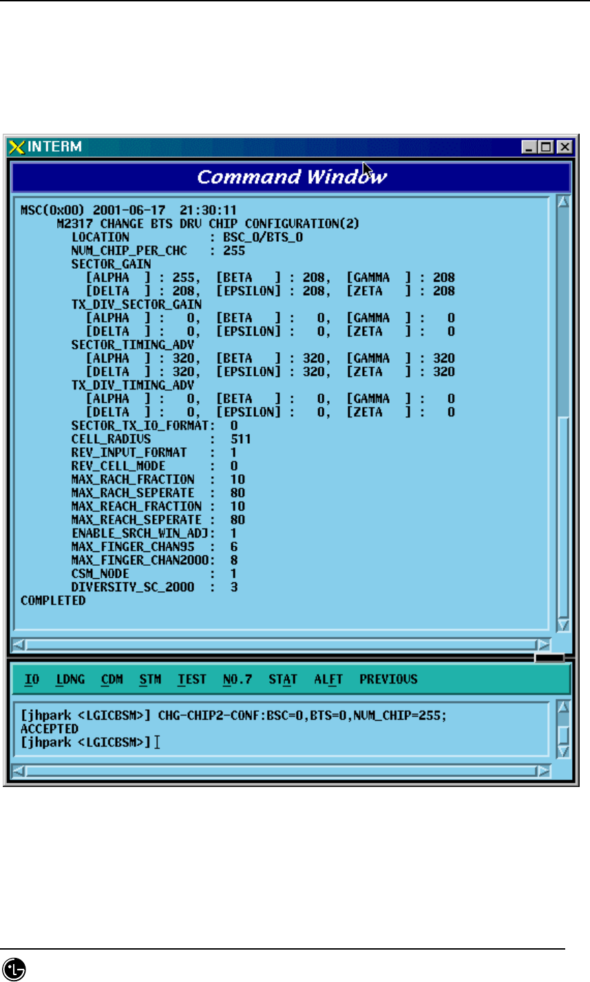
4.3.8.3. Channel Card Chip Configuration Information (2) Change
• Command CHG-CHIP2-CONF :BSC=a ,BTS=b [,NUM_CHIP=c] [,SECT_T_IO=d]
[,CELL_RADIUS=e] [,REV_IN_FORM=f] [,R_CELL_MODE=g]
[,MAX_RACH_F=h] [,MAX_RACH_S=i] [,MAX_REACH_F=j]
[,MAX_REACH_S=k] [,SRCH_WIN_ADJ=l] [,MAX_CH95=m]
[,MAX_CDMA2K=n] [,CSM_MODE=o] [,DIV_SCALE_2K=p];
STAREX-IS BSM Manual
Page:343(877)
Issue:1.
0
SMD-011-PMA210
• Input CHG-CHIP2-CONF: BSC=0, BTS=0,NUM_CHIP=255;
• Output
Fig. 4.3-135 Channel Card Chip Configuration Information (2) Change Display
STAREX-IS BSM Manual
Page:344(877)
Issue:1.
0
SMD-011-PMA210
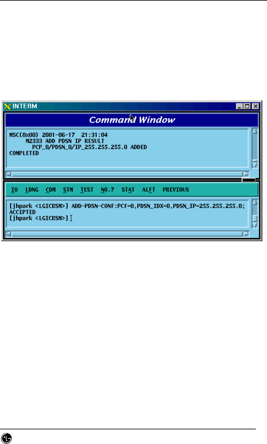
4.3.8.4. PDSN CONFIG Addition
• Command ADD-PDSN-CONF :PCF=a ,PDSN_IDX=b ,PDSN_IP=c;
• Input ADD-PDSN-CONF: BSC=0, BTS=0,PDSN_IP=255.255.255.0;
• Output
Fig. 4.3-136 PDSN Configuration Addition Display
STAREX-IS BSM Manual
Page:345(877)
Issue:1.
0
SMD-011-PMA210
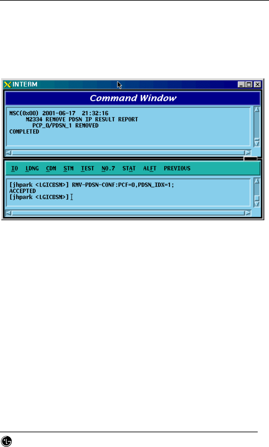
4.3.8.5. PDSN CONFIG Deletion
• Command RMV-PDSN-CONF :PCF=a ,PDSN_IDX=b;
• Input RMV-PDSN-CONF: BSC=0, BTS=0,PDSN_IDX=1;
• Output
Fig. 4.3-137 PDSN Configuration Deletion Display
STAREX-IS BSM Manual
Page:346(877)
Issue:1.
0
SMD-011-PMA210
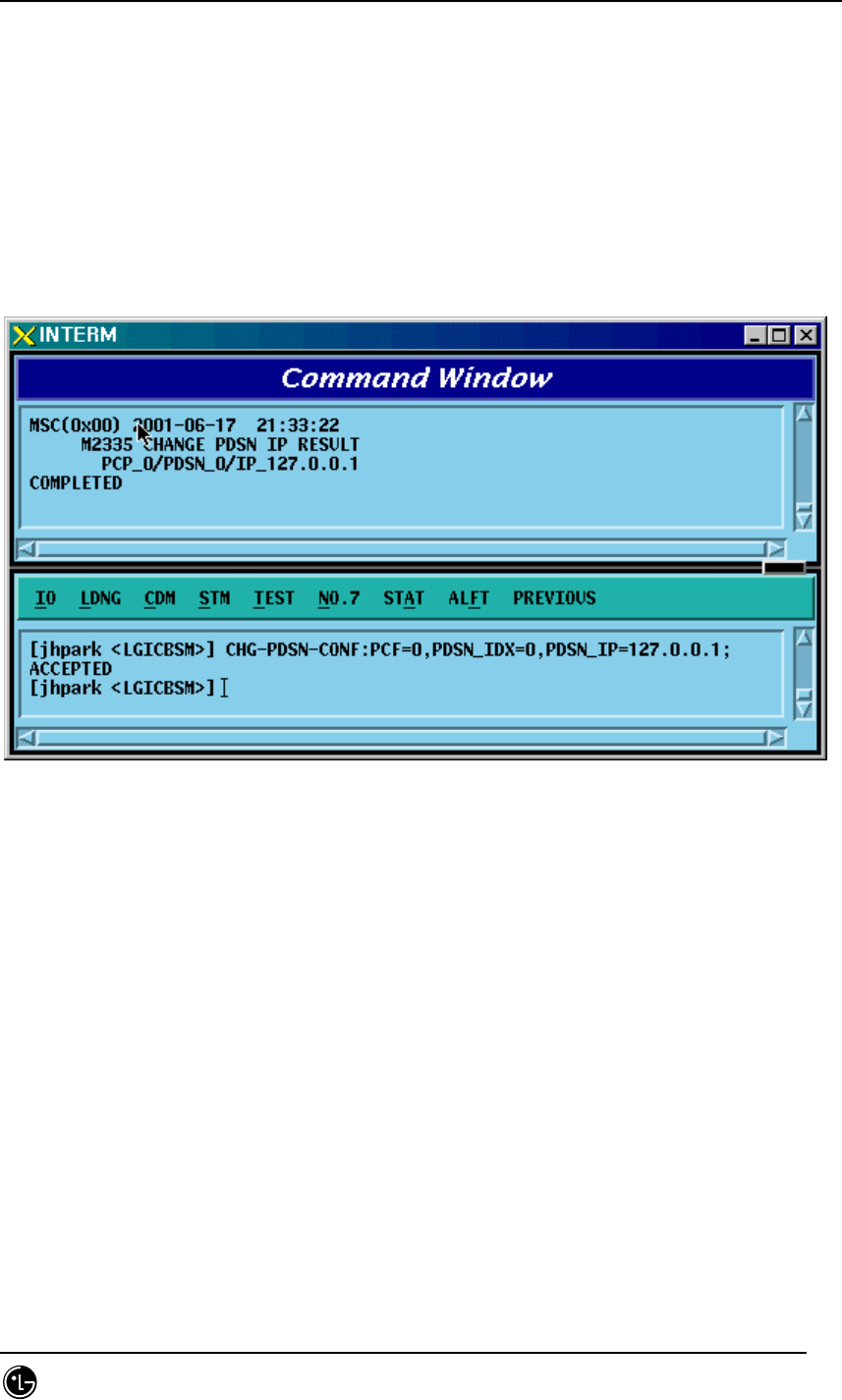
4.3.8.6. PDSN CONFIG Change
• Command CHG-PDSN-CONF :PCF=a ,PDSN_IDX=b ,PDSN_IP=c;
• Input CHG-PDSN-CONF: BSC=0, BTS=0,PDSN_IP=127.0.0.1;
• Output
Fig. 4.3-138 PDSN Configuration Change Display
STAREX-IS BSM Manual
Page:347(877)
Issue:1.
0
SMD-011-PMA210
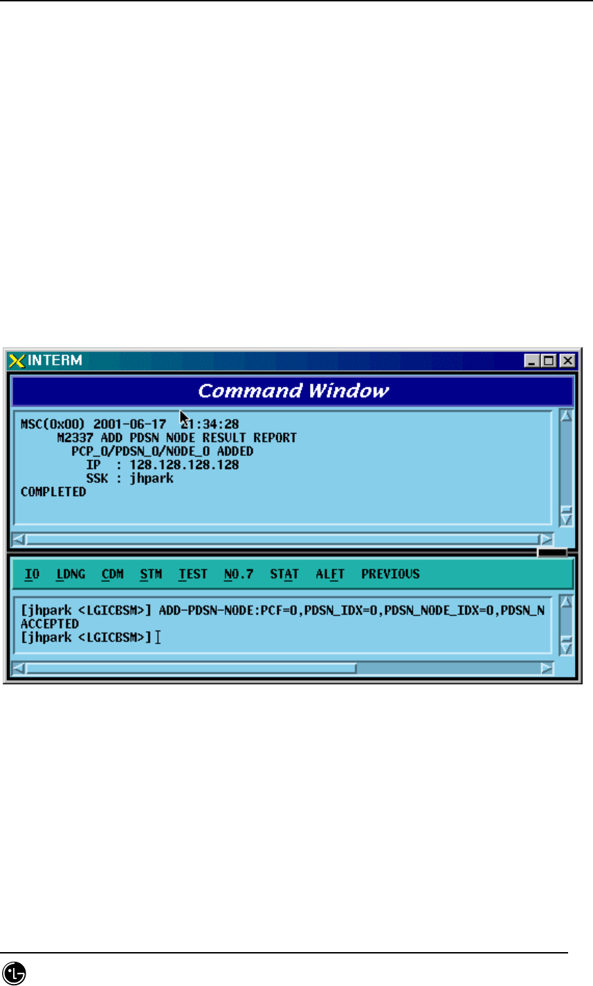
4.3.8.7. PDSN NODE Addition
• Command ADD-PDSN-NODE :PCF=a ,PDSN_IDX=b ,PDSN_NODE_IDX=c ,
PDSN_NODE_IP=d ,SSK_VALUE=e
• Input ADD-PDSN-NODE: BSC=0, BTS=0,PDSN_NODE_IDX=0,
PDSN_NODE_IP:128.128.128.128;
• Output
Fig. 4.3-139 PDSN NODE Addition Display
STAREX-IS BSM Manual
Page:348(877)
Issue:1.
0
SMD-011-PMA210
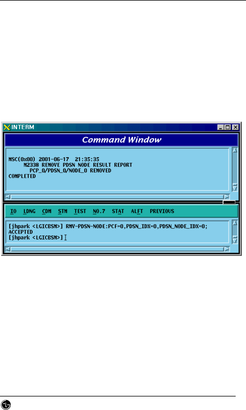
4.3.8.8. PDSN NODE Deletion
• Command RMV-PDSN-NODE :PCF=a ,PDSN_IDX=b ,PDSN_NODE_IDX=c;
• Input RMV-PDSN-NODE: BSC=0, BTS=0,PDSN_IDX=0,PDSN_NODE_IDX=0;
• Output
Fig. 4.3-140 PDSN NODE Deletion Display
STAREX-IS BSM Manual
Page:349(877)
Issue:1.
0
SMD-011-PMA210
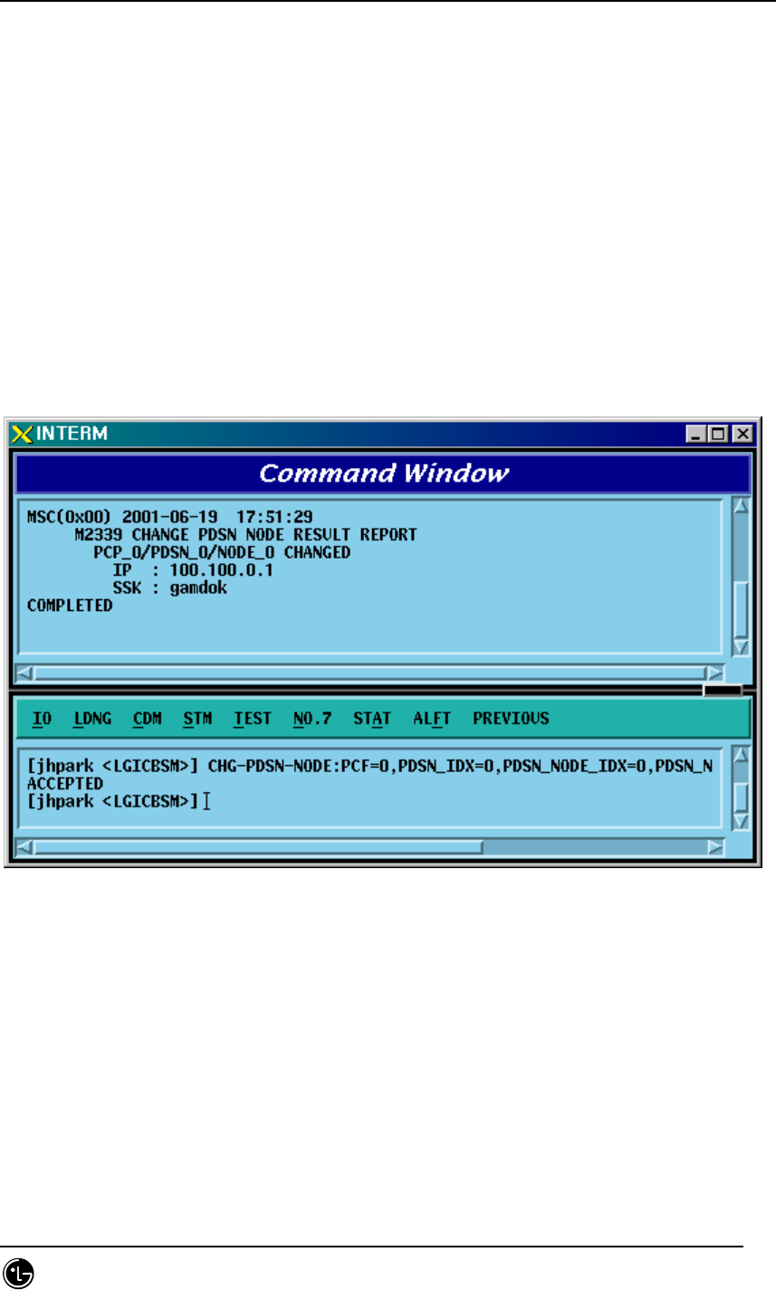
4.3.8.9. PDSN NODE Change
• Command CHG-PDSN-NODE :PCF=a ,PDSN_IDX=b ,PDSN_NODE_IDX=c
[,PDSN_NODE_IP=d] [,SSK_VALUE=e]
• Input CHG-PDSN-NODE: BSC=0, BTS=0,PDSN_IDX=0,PDSN_NODE_IDX=0,
PDSN_NODE_IP=100.100.0.1, SSK_VALUE=gamdok;
• Output
Fig. 4.3-141 PDSN NODE Change Display
STAREX-IS BSM Manual
Page:350(877)
Issue:1.
0
SMD-011-PMA210
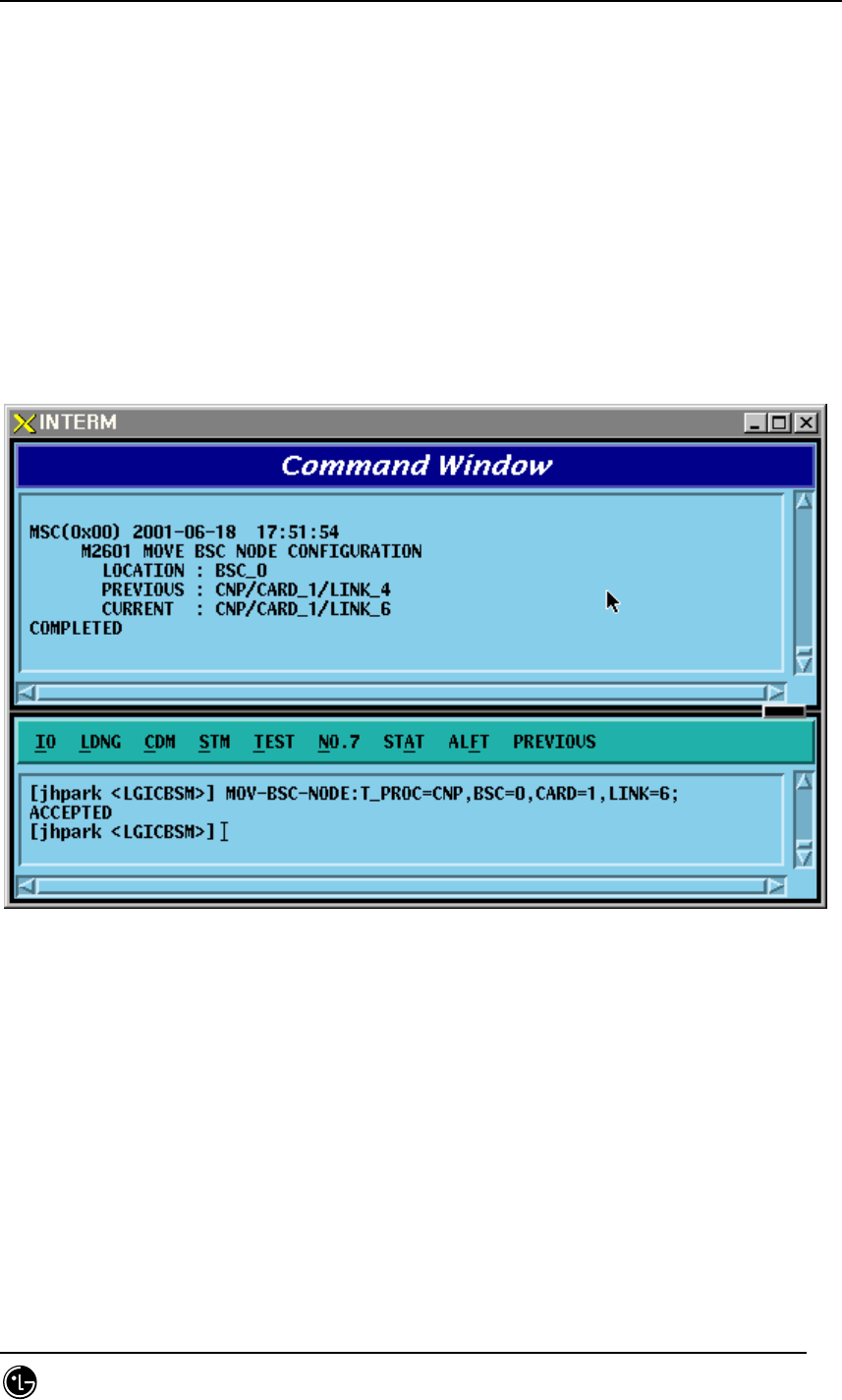
4.3.8.10. BSC Node Movement
• Command MOV-BSC-NODE :T_PROC=a ,BSC=b ,CARD=c ,LINK=d;
• Input MOV-BSC-NODE: T_PROC=CNP,BSC=0,CARD=1,LINK=6;;
• Output
Fig. 4.3-142 BSC NODE Movement Display

STAREX-IS BSM Manual
Page:351(877)
Issue:1.
0
SMD-011-PMA210
4.3.8.11. PCF Node Movement
• Command MOV-PCF-NODE :PCF=a ,CARD0=b ,LINK0=c ,CARD1=d ,LINK1=e
,CARD2=f ,LINK2=g ,CARD3=h ,LINK3=i;
• Input MOV-PCF-NODE: BSC=0, BTS=0,PA_TYPE=FA_NEQ;
• Output
STAREX-IS BSM Manual
Page:352(877)
Issue:1.
0
SMD-011-PMA210
4.3.8.12. SMP Node Movement
• Command MOV-SMP-NODE :BSC=a ,SMP=b ,CARD=c ,LINK=d;
• Input MOV-SMP-NODE: BSC=0, SMP=0,CARD=1,LINK=6
• Output
Fig. 4.3-143 SMP NODE Movement Display
STAREX-IS BSM Manual
Page:353(877)
Issue:1.
0
SMD-011-PMA210
4.3.8.13. VMP Node Movement
• Command MOV-VMP-NODE :BSC=a ,VMP=b ,CARD=c ,LINK=d;
• Input MOV-VMP-NODE: BSC=0, VMP=0, CARD=1, LINK=6;
• Output
Fig. 4.3-144 VMP NODE Movement Display

STAREX-IS BSM Manual
Page:354(877)
Issue:1.
0
SMD-011-PMA210
4.3.8.14. BTS ID Movement
• Command MOV-BTS-ID :BSC=a ,OLD_BTS=b ,NEW_BTS=c;
• Input MOV-BTS-ID: BSC=0, OLD_BTS=0,NEW_BTS=2;
• Output
Fig. 4.3-145 BTS ID Movement Display
STAREX-IS BSM Manual
Page:355(877)
Issue:1.
0
SMD-011-PMA210
4.3.8.15. BTS TRUNK Node Movement
For this command, execute DIS-TRNK-DATA first to input the parameter value.
• Command MOV-BTS-TRNK :BSC=a ,BTS=b ,OLD_ALMA=c ,OLD_ALPA=d ,
OLD_ALPA_LINK=e ,NEW_ALMA=f ,NEW_ALPA=g ,NEW_ALPA_LINK=h;
• Input MOV-BTS-TRNK: BSC=0, BTS=2,
OLD_ALMA=0,OLD_ALPA=0,OLD_ALPA_LINK=0,
NEW_ALMA=1,NEW_ALPA=1,NEW_ALPA_LINK=1;
• Output
Fig. 4.3-146 BTS TRUNK Movement display
STAREX-IS BSM Manual
Page:356(877)
Issue:1.
0
SMD-011-PMA210
4.3.8.16. LICA LINK Movement
• Command MOV-LICA-
LINK :BSC=a ,BTS=b ,OLD_LICA=c ,OLD_LINK=d ,NEW_LICA=e
,NEW_LINK=f;
• Input MOV-LICA-LINK: BSC=0, BTS=1,
OLD_LICA=0, OLD_LINK=0,
NEW_LICA=1, NEW_LINK=1;
• Output
Fig. 4.3-147 LICA LINK Movement Display
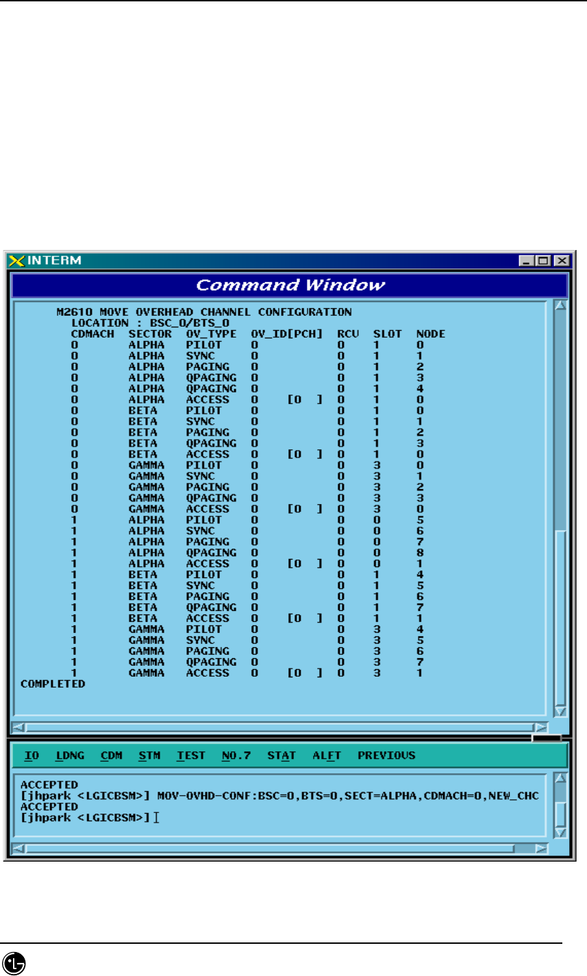
STAREX-IS BSM Manual
Page:357(877)
Issue:1.
0
SMD-011-PMA210
4.3.8.17. OVERHEAD CHANNEL Configuration Information Movement
Refer to DIS-OVHD-CONF command
• Command MOV-OVHD-CONF :BSC=a ,BTS=b ,SECT=c ,CDMACH=d ,
NEW_CHC=e ;
• Input MOV-OVHD-CONF: BSC=0, BTS=0,
SECTOR=ALPHA,CDMACH=0,NEW_CHC=1;
• Output
Fig. 4.3-148 OVHD Channel Configuration Information Movement Display

STAREX-IS BSM Manual
Page:358(877)
Issue:1.
0
SMD-011-PMA210
4.3.8.18. BSC Configuration Addition
• Command ADD-BSC-CONF :T_PROC=a ,BSC=b ,CARD=c ,LINK=d;
• Input ADD-BSC-CONF: BSC=0, BTS=0,PA_TYPE=FA_NEQ;
• Output

STAREX-IS BSM Manual
Page:359(877)
Issue:1.
0
SMD-011-PMA210
4.3.8.19. BSC Configuration Deletion
• Command RMV-BSC-CONF :T_PROC=a ,BSC=b;
• Input RMV-BSC-CONF: BSC=0, BTS=0,PA_TYPE=FA_NEQ;
• Output

STAREX-IS BSM Manual
Page:360(877)
Issue:1.
0
SMD-011-PMA210
4.3.8.20. PCF Configuration Addition
• Command ADD-PCF-CONF :PCF=a ,CARD0=b ,LINK0=c ,CARD1=d ,LINK1=e
,CARD2=f ,LINK2=g ,CARD3=h ,LINK3=i;
• Input ADD-PCF-
CONF:PCF=1,CARD0=3,LINK0=4,CARD1=3,LINK1=4,CARD2=3,LINK2=4,CARD3=3,LI
NK3=4;
• Output
Fig. 4.3-149 PCF Configuration Addition Display
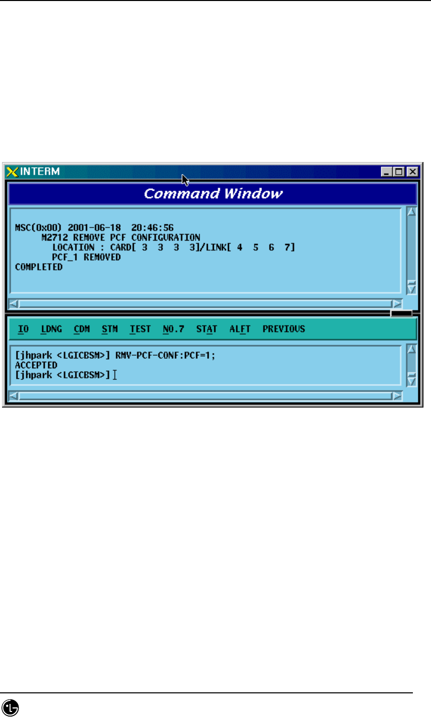
STAREX-IS BSM Manual
Page:361(877)
Issue:1.
0
SMD-011-PMA210
4.3.8.21. PCF Configuration Deletion
• Command RMV-PCF-CONF :PCF=a;
• Input RMV-PCF-CONF: PCF=1;
• Output
Fig. 4.3-150 PCF Configuration Deletion Display
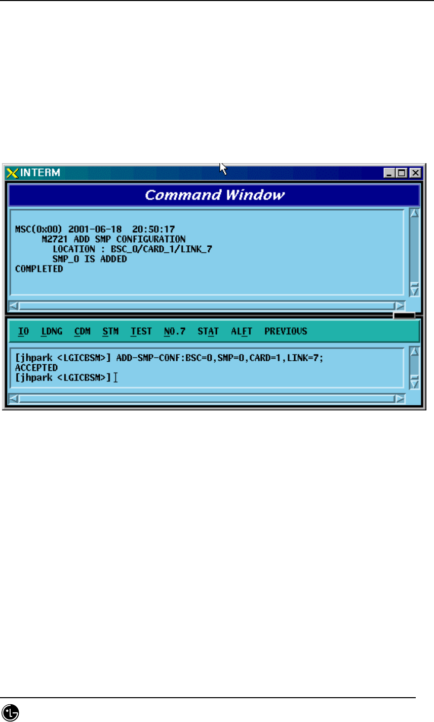
STAREX-IS BSM Manual
Page:362(877)
Issue:1.
0
SMD-011-PMA210
4.3.8.22. SMP Configuration Addition
• Command ADD-SMP-CONF :BSC=a ,SMP=b ,CARD=c ,LINK=d;
• Input ADD-SMP-CONF: BSC=0,SMP=0,CARD=1,LINK=7;
• Output
Fig. 4.3-151 SMP Configuration Addition Display
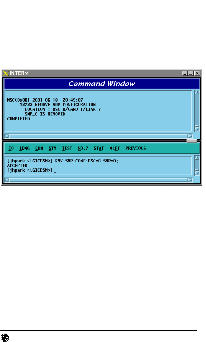
STAREX-IS BSM Manual
Page:363(877)
Issue:1.
0
SMD-011-PMA210
4.3.8.23. SMP Configuration Deletion
• Command RMV-SMP-CONF :BSC=a ,SMP=b;
• Input RMV-SMP-CONF: BSC=0, SMP=0;
• Output
Fig. 4.3-152 SMP Configuration Deletion Display
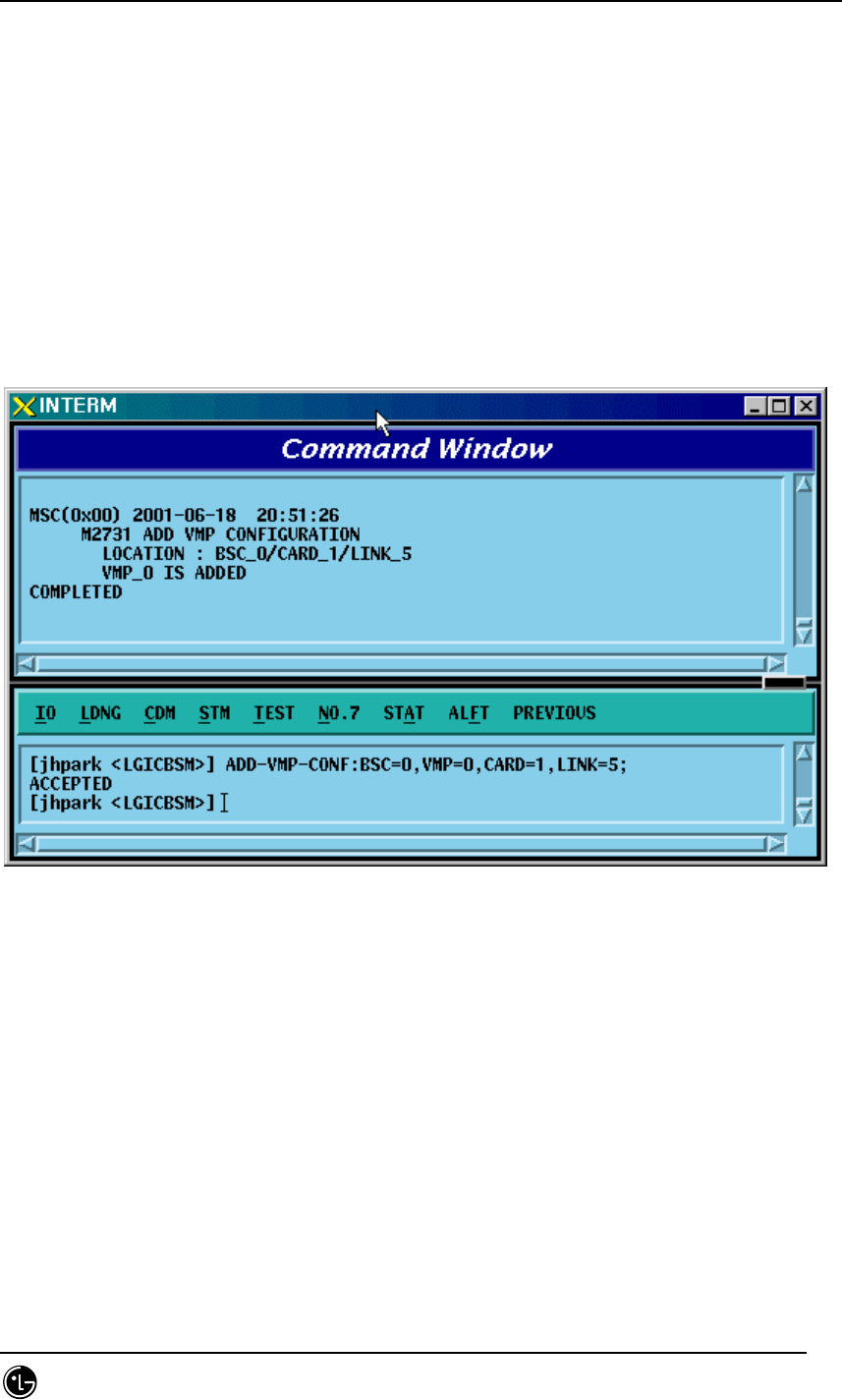
STAREX-IS BSM Manual
Page:364(877)
Issue:1.
0
SMD-011-PMA210
4.3.8.24. VMP Configuration Addition
• Command ADD-VMP-CONF :BSC=a ,VMP=b ,CARD=c ,LINK=d;
• Input ADD-VMP-CONF: BSC=0,VMP=0,CARD=1,LINK=5;
• Output
Fig. 4.3-153 VMP Configuration Addition Display
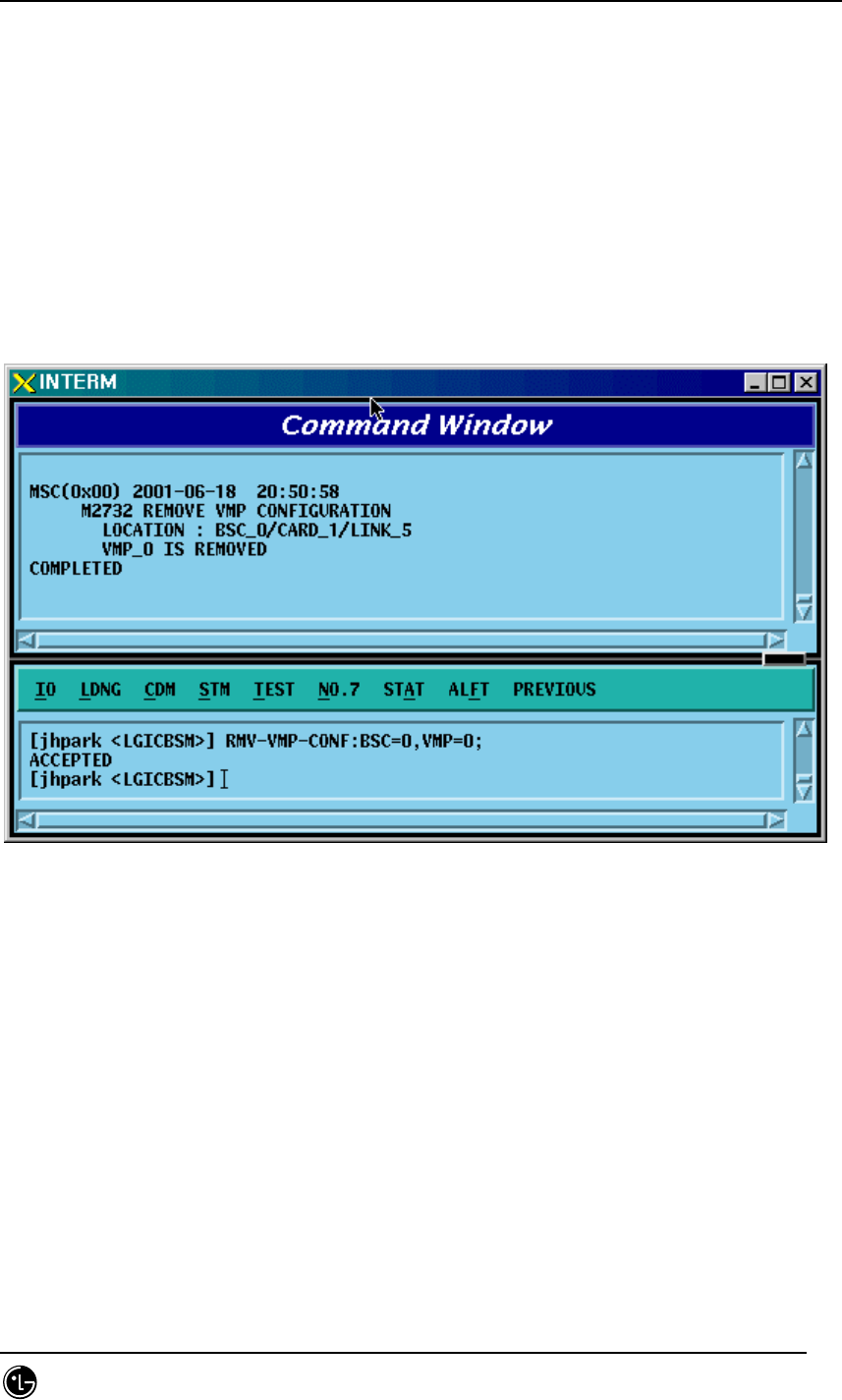
STAREX-IS BSM Manual
Page:365(877)
Issue:1.
0
SMD-011-PMA210
4.3.8.25. VMP Configuration Deletion
• Command RMV-VMP-CONF :BSC=a ,VMP=b;
• Input RMV-VMP-CONF: BSC=0, VMP=0;
• Output
Fig. 4.3-154 VMP Configuration Deletion Display
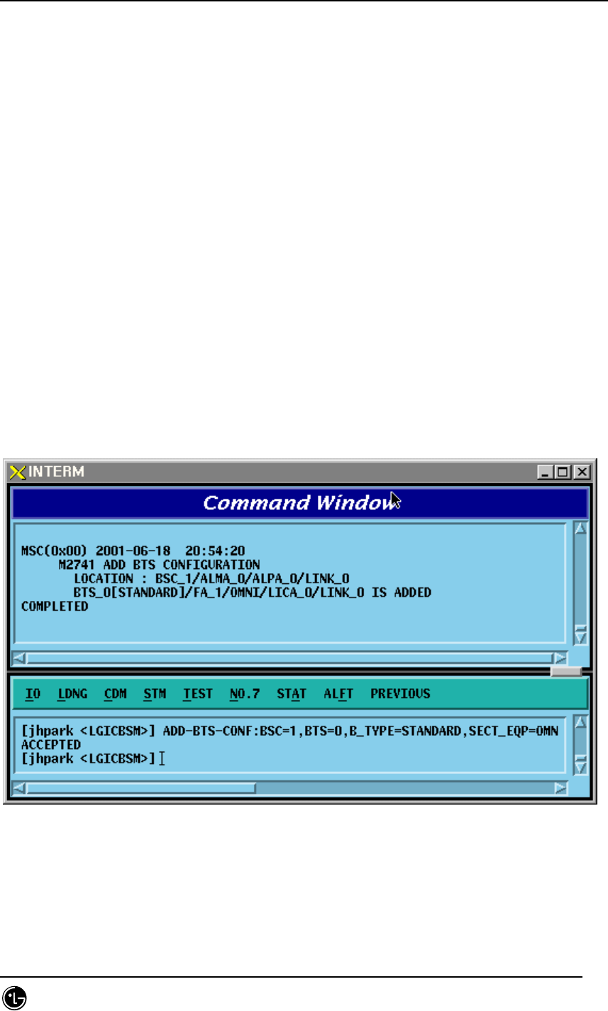
STAREX-IS BSM Manual
Page:366(877)
Issue:1.
0
SMD-011-PMA210
4.3.8.26. BTS Configuration Addition
• Command ADD-BTS-
CONF :BSC=a ,BTS=b ,B_TYPE=c ,SECT_EQP=d ,SECT_RANGE=e
,ALMA=f ,ALPA=g ,ALPA_LINK=h ,LICA=i ,LICA_LINK=j
,FA0_CH_NUM=k ,PN_ALPHA=l [,PN_BETA=m]
[,PN_GAMMA=n] [,PN_DELTA=o] [,PN_EPSILON=p]
[,PN_ZETA=q] [,PA_TYPE=r] [,ANT_TYPE=s] [,LNA_TYPE=t]
[,RISA_EQP=u] [,BOTA_EQP=v];
• Input Input ADD-BTS-CONF: BSC=0, BTS=0; -> ADD-BTS-CONF: BSC=1,
BTS=0,B_TYPE=STANDARD,SECT_EQP=OMNI;
• Output
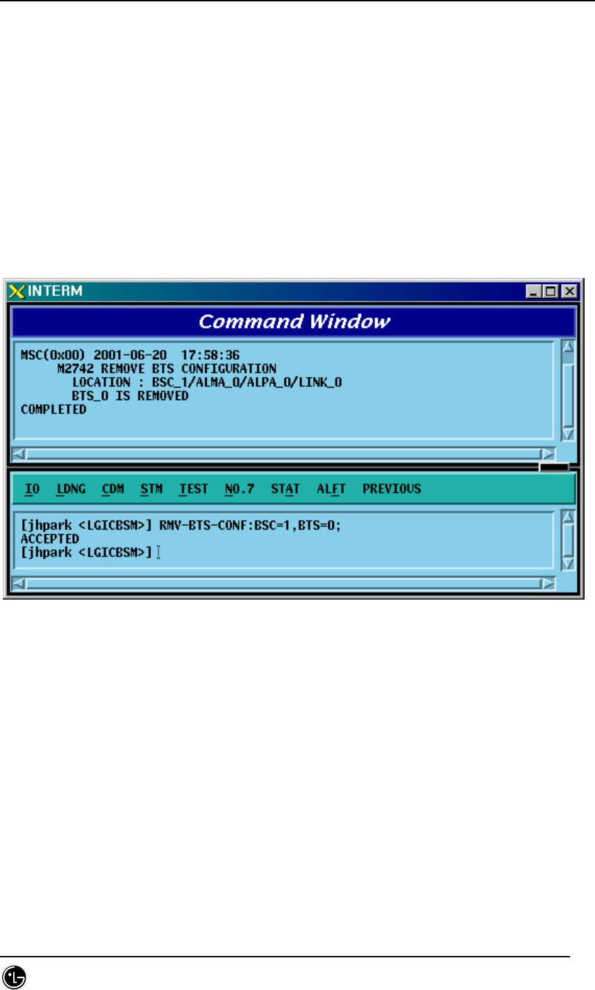
STAREX-IS BSM Manual
Page:367(877)
Issue:1.
0
SMD-011-PMA210
4.3.8.27. BTS Configuration Deletion
• Command RMV-BTS-CONF :BSC=a ,BTS=b;
• Input RMV-BTS-CONF: BSC=1, BTS=0;
• Output
Fig. 4.3-155 BTS Configuration Deletion Display

STAREX-IS BSM Manual
Page:368(877)
Issue:1.
0
SMD-011-PMA210
4.3.8.28. SECTOR Configuration Addition
• Command ADD-SECT-CONF :BSC=a ,BTS=b ,SECT=c ,PN=d;
• Input ADD-SECT-CONF: BSC=0, BTS=0,PA_TYPE=FA_NEQ;
• Output

STAREX-IS BSM Manual
Page:369(877)
Issue:1.
0
SMD-011-PMA210
4.3.8.29. SECTOR Configuration Deletion
• Command RMV-SECT-CONF :BSC=a ,BTS=b ,SECT=c;
• Input RMV-SECT-CONF: BSC=0, BTS=0,PA_TYPE=FA_NEQ;
• Output
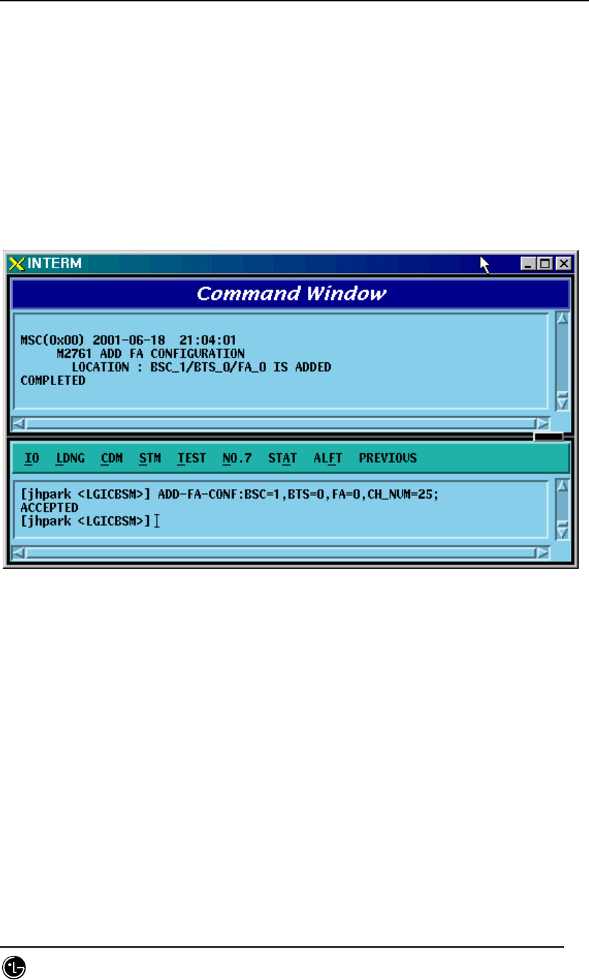
STAREX-IS BSM Manual
Page:370(877)
Issue:1.
0
SMD-011-PMA210
4.3.8.30. FA Configuration Addition
• Command ADD-FA-CONF :BSC=a ,BTS=b ,FA=c ,CH_NUM=d;
• Input ADD-FA-CONF: BSC=1, BTS=0,FA=0,CH_NUM=25;
• Output
Fig. 4.3-156 FA Configuration Addition Display
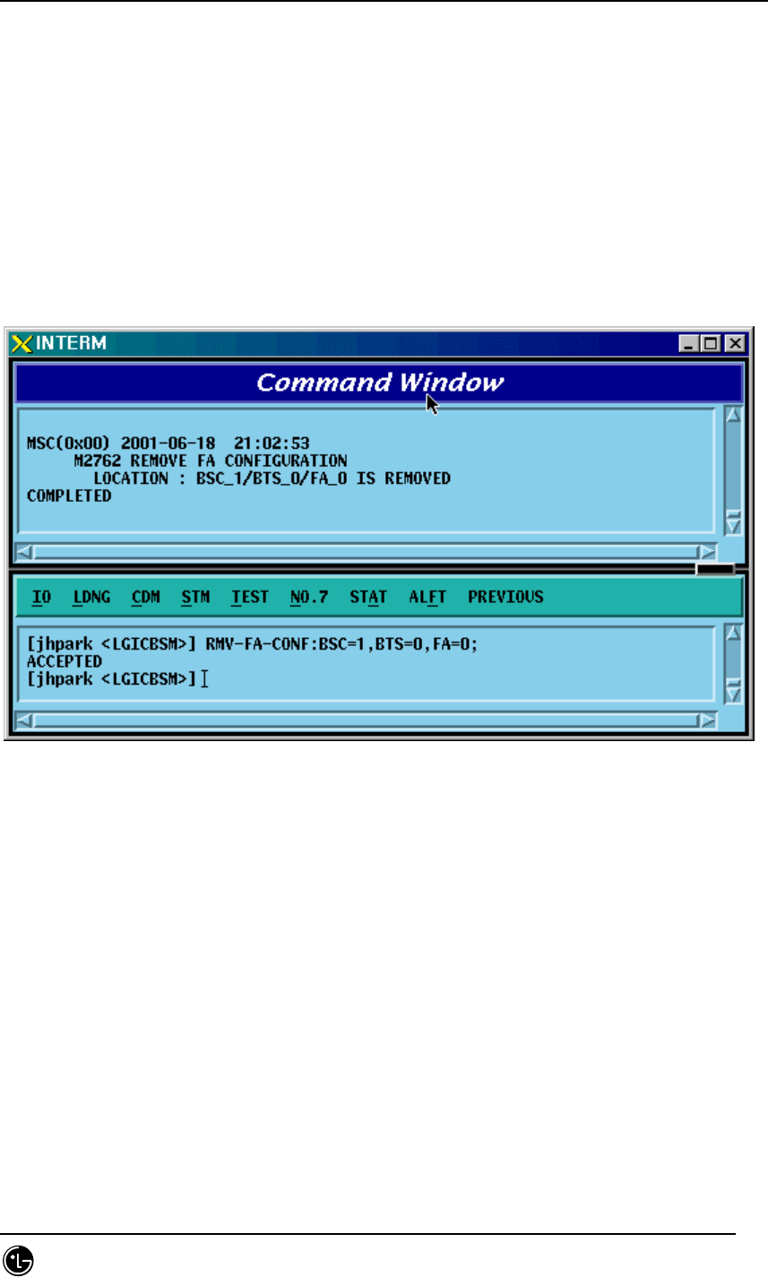
STAREX-IS BSM Manual
Page:371(877)
Issue:1.
0
SMD-011-PMA210
4.3.8.31. FA Configuration Deletion
• Command RMV-FA-CONF :BSC=a ,BTS=b ,FA=c;
• Input RMV-FA-CONF: BSC=1, BTS=0,FA=0;
• Output
Fig. 4.3-157 FA Configuration Deletion Display

STAREX-IS BSM Manual
Page:372(877)
Issue:1.
0
SMD-011-PMA210
4.3.8.32. BSC-BTS TRUNK Configuration Addition
• Command ADD-TRNK-CONF :BSC=a ,BTS=b ,ALMA=c ,ALPA=d ,ALPA_LINK=e
,LICA=f ,LICA_LINK=g ,ALLOC_TYPE=h;
• Input ADD-TRNK-CONF: BSC=0, BTS=0,PA_TYPE=FA_NEQ;
• Output

STAREX-IS BSM Manual
Page:373(877)
Issue:1.
0
SMD-011-PMA210
4.3.8.33. BSC-BTS TRUNK Configuration Deletion
• Command RMV-TRNK-CONF :BSC=a ,BTS=b ,ALMA=c ,ALPA=d ,ALPA_LINK=e ;
• Input RMV-TRNK-CONF: BSC=0, BTS=0,PA_TYPE=FA_NEQ;
• Output
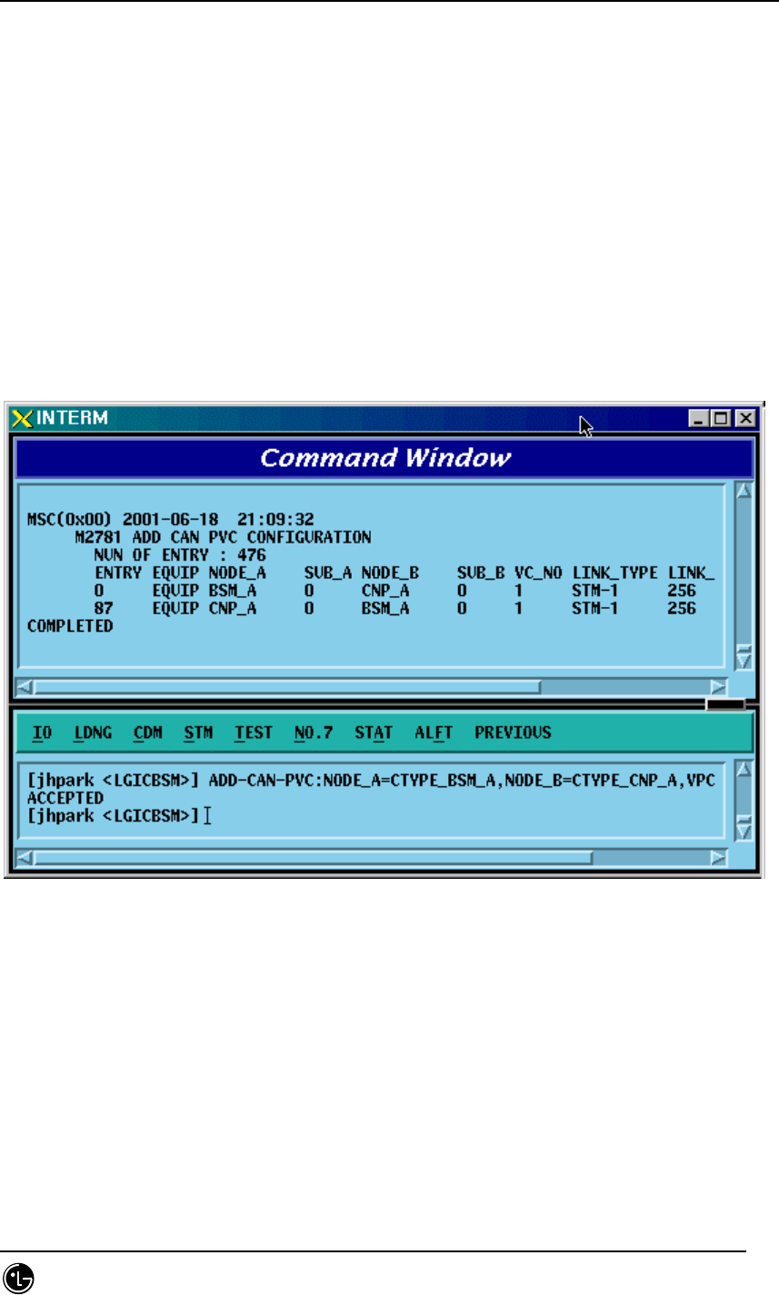
STAREX-IS BSM Manual
Page:374(877)
Issue:1.
0
SMD-011-PMA210
4.3.8.34. CAN PVC Configuration Addition
• Command ADD-CAN-PVC :NODE_A=a ,NODE_B=b ,VPCI_A=c ,VPCI_B=d
[,NO_VC=e] ;
• Input ADD-CAN-PVC: NODE_A=CTYPE_BSM_A, NODE_B=CTYPE_CNP_A,
VPCL_A=0,VPCL_B=0;
• Output
Fig. 4.3-158 CAN PVC Configuration Addition Display

STAREX-IS BSM Manual
Page:375(877)
Issue:1.
0
SMD-011-PMA210
4.3.8.35. CAN PVC Configuration Deletion
• Command RMV-CAN-PVC :INDEX=a;
• Input RMV-CAN-PVC: INDEX=0;
• Output
Fig. 4.3-159 CAN PVC Configuration Deletion Display
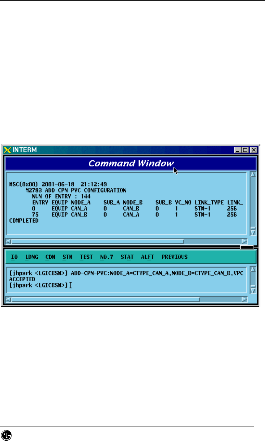
STAREX-IS BSM Manual
Page:376(877)
Issue:1.
0
SMD-011-PMA210
4.3.8.36. CPN PVC Configuration Addition
• Command ADD-CPN-PVC :NODE_A=a ,NODE_B=b ,VPCI_A=c ,VPCI_B=d
[,NO_VC=e] ;
• Input ADD-CPN-PVC:NODE_A=CTYPE_CAN_A, NODE_B=CTYPE_CAN_B,
VPCI_A=0, VPCI_B=0;
• Output
Fig. 4.3-160 CPN PVC Configuration Addition Display
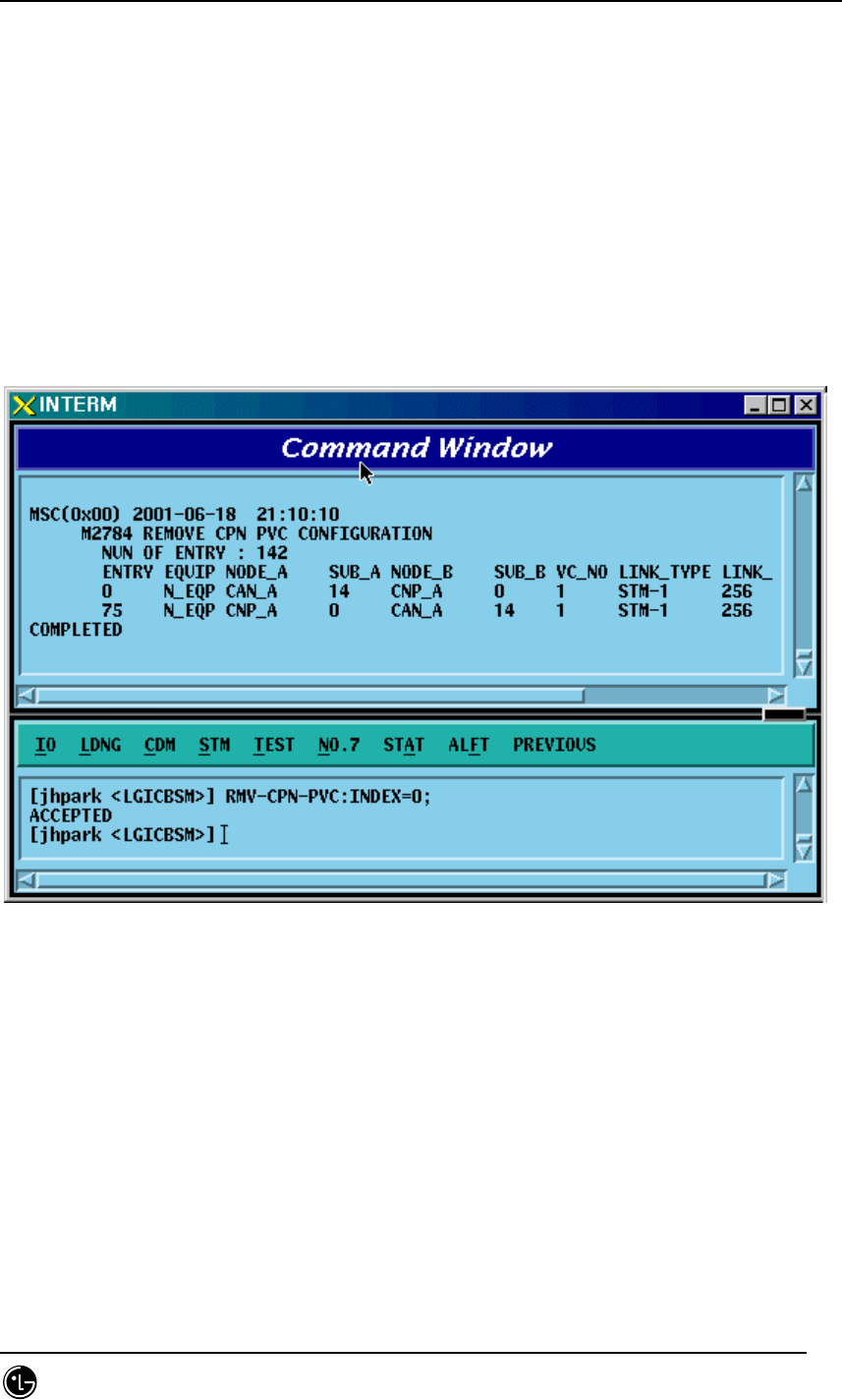
STAREX-IS BSM Manual
Page:377(877)
Issue:1.
0
SMD-011-PMA210
4.3.8.37. CPN PVC Configuration Deletion
• Command RMV-CPN-PVC :INDEX=a;
• Input RMV-CPN-PVC: INDEX=0;
• Output
Fig. 4.3-161 CPN PVC Configuration Deletion Display
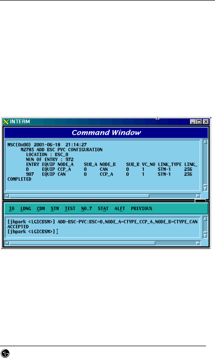
STAREX-IS BSM Manual
Page:378(877)
Issue:1.
0
SMD-011-PMA210
4.3.8.38. BSC PVC Configuration Addition
• Command ADD-BSC-PVC :BSC=a ,NODE_A=b ,NODE_B=c ,VPCI_A=d ,VPCI_B=e
[,NO_VC=f];
• Input ADD-BSC-PVC:BSC=0, NODE_A=CTYPE_CCP_A, NODE_B=CTYPE_CCP_B,
VPCI_A=0, VPCI_B=0;
• Output
Fig. 4.3-162 BSC PVC Configuration Addition Display
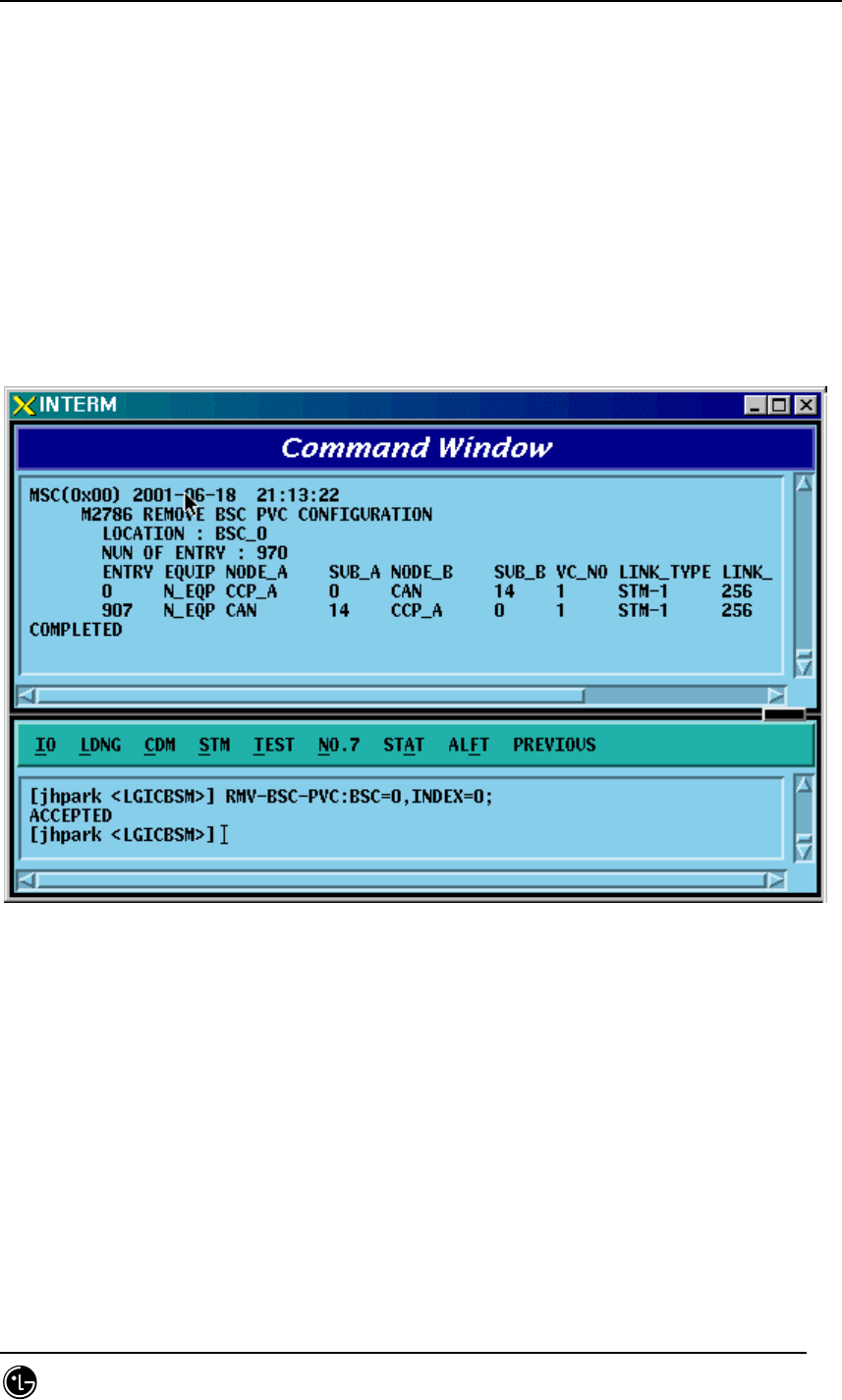
STAREX-IS BSM Manual
Page:379(877)
Issue:1.
0
SMD-011-PMA210
4.3.8.39. BSC PVC Configuration Deletion
• Command RMV-BSC-PVC :BSC=a ,INDEX=b;
• Input RMV-BSC-PVC:BSC=0, INDEX=0;
• Output
Fig. 4.3-163 BSC PVC Configuration Deletion Display
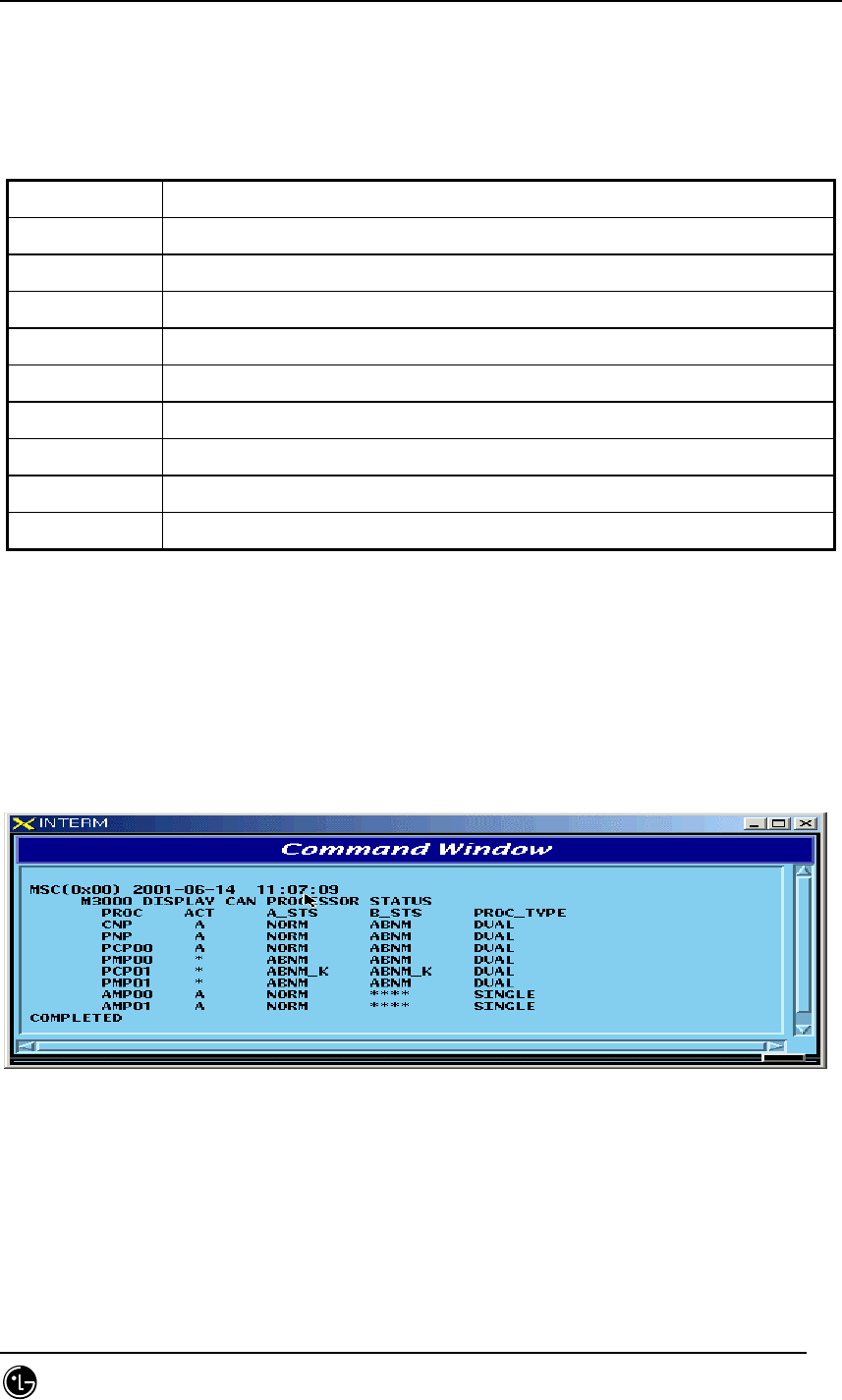
STAREX-IS BSM Manual
Page:380(877)
Issue:1.
0
SMD-011-PMA210
4.4. STATUS COMMAND
4.4.1 PROCESSOR STATUS CONTROL
Table 4.4-1 Processor Status LIST
Status Types Definition
NORM NORMAL
ABNM Abnormal
DCPY Dual Copy
LDNG StandBy Loading
NORM(OLD) Normal (After StandBy Loading, Old version)
NORM(NEW) Normal (After StandBy Loading, New version)
ABN_K Abnormal with Keep Alive Fault
ABN_I Abnormal with Process Isolation
UNDEF Undefined Status
4.4.1.1. BSM CAN PROCESSOR STATUS DISPLAY COMMAND
Function to display processor status inserted in CAN.
Command : DIS-CAN-PRC;
Input : DIS-CAN-PRC;
Fig. 4.4-1 Result of CAN Processor Status Display Command
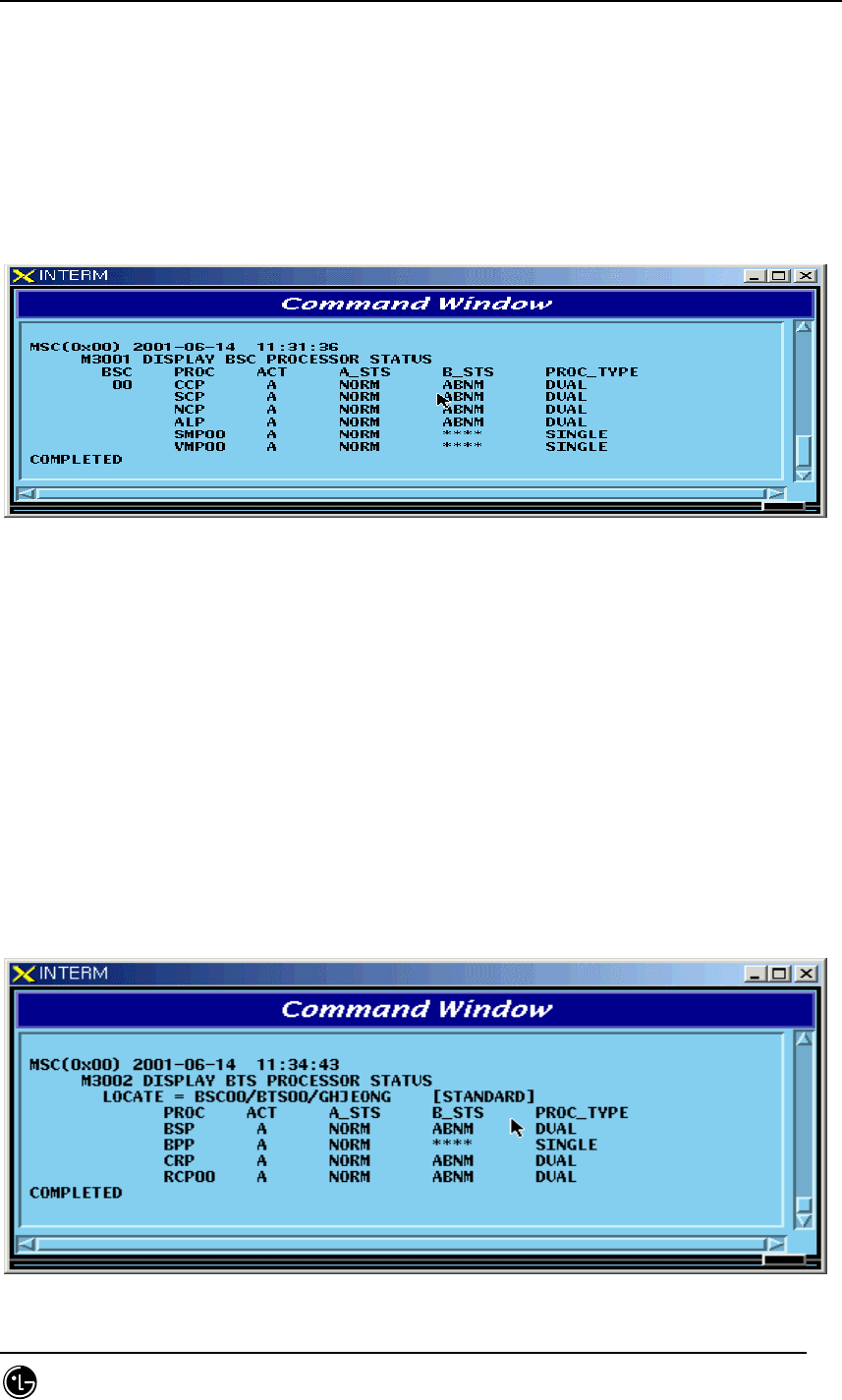
STAREX-IS BSM Manual
Page:381(877)
Issue:1.
0
SMD-011-PMA210
4.4.1.2. BSC Processor Status Display Command
Function to display Processor status inserted in BSC.
Command : DIS-BSC-PRC[:BSC=a];
a : BSC Number(0~11)
Input : DIS-BSC-PRC:BSC=0;
Fig. 4.4-2 Result of BSC Processor Status Display
4.4.1.3. Status Display Command of BTS Processor
Function to display operation status of processors mounted in all the BTSs within the
corresponding BSC or in each BTS
Command : DIS-BTS-STS:BSC=a[,BTS=b];
a:BSC Number (0~11)
b:BTS Number (0~47)
Input : DIS-BTS-STS:BSC=0,BTS=0;
Output
Fig. 4.4-3 Result of BTS Processor Status Display Command
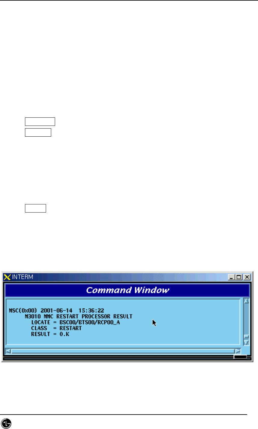
STAREX-IS BSM Manual
Page:382(877)
Issue:1.
0
SMD-011-PMA210
4.4.1.4. Processor Restart Command
Function to restart Processors
• Command : RST-PRC[:BSC=a][,BTS=b],RANGE=c,SIDE=d,CLS=e;
a : BSC Number (0~11)
b : BTS Number (0~47)
c : Scope of restart(All the Processors of CCP, PNP,NCP,PCP., etc.)
d : Side to restart (A,B,BOTH)
e : Class (RESTART, REBOOT, FLASH)
RESTART : Restart O/S and receive loading of PLD only.
REBOOT : It executes BOOTER. In case of the processors equipped with Flash
ROM, they check upper level processors and version of each block. If they are
different, they receive loading from the upper level processors. However, if
they are the same, they do not receive loading from the upper level
processors. The processors with no Flash ROM receive loading from the upper
level processors without checking version.
. For reference, Active Side before and after reboot does not change.
FLASH : Delete Flash content of the Processor with Flash ROM equipped and
reboot it to receive loading of all the files from the upper level Processor. For
reference, Active Side before and after Flash Reboot changes.
Input : RST-PRC:BSC=0,BTS=0,RANGE=RCP00,SIDE=A,CLS=RESTART;
Fig. 4.4-4 Result of Processor Restart Command
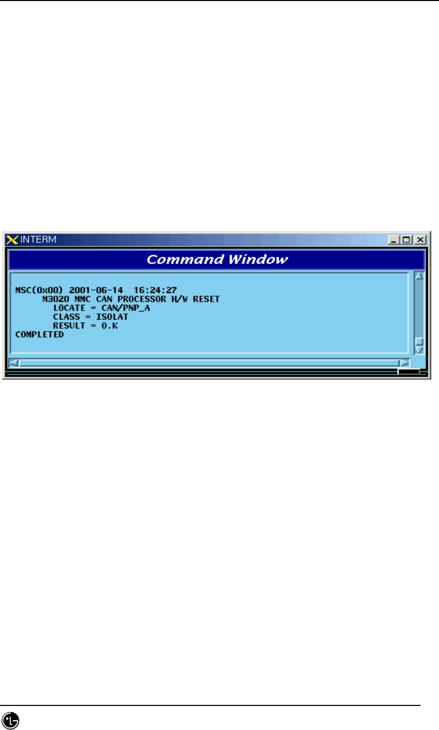
STAREX-IS BSM Manual
Page:383(877)
Issue:1.
0
SMD-011-PMA210
4.4.1.5. CAN Processor H/W RESET(ISOLATION) COMMAND
Function to reset CAN Processor H/W.
Command : RMT-CAN-PRC:PROC=a,SIDE=b,CLS=c;
a: Processor Name : CNP,PNP,PCP,PMP
b: Side : A,B
c: CLASS : HARDRST,ISOLAT,UNISOL
HARDRST : Function to reset Processor on H/W Level (using Register Setting).
ISOLAT : Function to isolate Processor on H/W Level (maintaining Status of RESET)
UNISOL : Function to release the isolation
Input : RMT-CAN-PRC:PROC=PNP,SIDE=A,CLS=ISOLAT;
Fig. 4.4-5 CAN Processor H/W Command Result
4.4.1.6. BSC Processor H/W RESET(ISOLATION) COMMAND
Function to reset BSC Processor H/W.
Command : RMT-BSC-PRC:BSC=a,PROC=b,[SIDE=c],CLS=d;
a: BSC Number
b: Processor Name : CCP,NCP,SCP,ALP,SMP,VMP
c: Side : A,B
d: CLASS : HARDRST,ISOLAT,UNISOL
HARDRST : Function to RESET Processor on H/W Level (using Register Setting).
ISOLAT : Function to isolate Processor on H/W Level (RESET Status maintained)
UNISOL : Function to release isolation
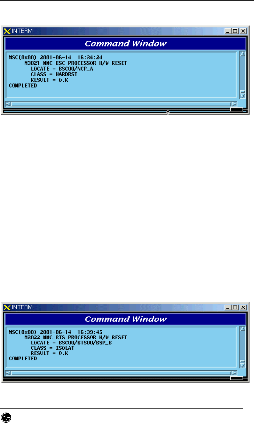
STAREX-IS BSM Manual
Page:384(877)
Issue:1.
0
SMD-011-PMA210
Input : RMT-BSC-PRC:BSC=0,PROC=NCP,SIDE=A,CLS=ISOLAT;
Fig. 4.4-6 BSC Processor H/W Command Result
4.4.1.7. BTS Processor H/W RESET(ISOLATION) COMMAND
Function to BSC Processor H/W.
Command : RMT-BTS-PRC:BSC=a,BTS=b,PROC=c,[SIDE=d],CLS=e;
a: BSC Number
b: BTS Number
c: Processor Name : BSP,BPP,CRP,RCP(00~05)
d: Side : A,B
e: CLASS : HARDRST,ISOLAT,UNISOL
HARDRST : Function to RESET Processor on H/W Level (using Register Setting).
ISOLAT : Function to isolate Processor on H/W Level (RESET Status maintained)
UNISOL : Function to release isolation
Input : RMT-BTS-PRC:BSC=0,BTS=0,PROC=BSP,SIDE=A,CLS=ISOLAT;
Fig. 4.4-7 BTS Processor H/W RESET(ISOLATION) Command Display Result
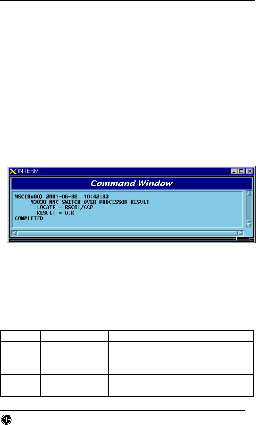
STAREX-IS BSM Manual
Page:385(877)
Issue:1.
0
SMD-011-PMA210
4.4.1.8. Processor Switch Over(Switch) Command
Function to Switch over Processor.
Switching Over Command is executed for duplicated Processors and is performed only
when both sides of Processors are in a normal status.
Command : SWT-PRC [:BSC=a] [,BTS=b] ,PROC=c;
a: BSC Number
b: BTS Number
c: Processor Name : CNP, PNP, PCP00, PCP01,PCP02, PMP00, PMP01,PMP02,
CCP, NCP, SCP,ALP, BSP, CRP, RCP00, RCP01, RCP02, RCP03,RCP04, RCP05
Input : SWT-PRC :BSC=1 ,PROC=CCP;
Fig. 4.4-8 Processor Switch Over(Switch) Command Display Result
4.4.2. Network Status Control
Table 4.4-2 Network Node Status LIST
Status Types Definition Description
NORM Normal Normal Operation
NOR_A Normal Act While normally operated, Act Status is
maintained (Duplicated node)
NOR_S Normal Standby While normally operated, Standby Status is
maintained (Duplicated node)
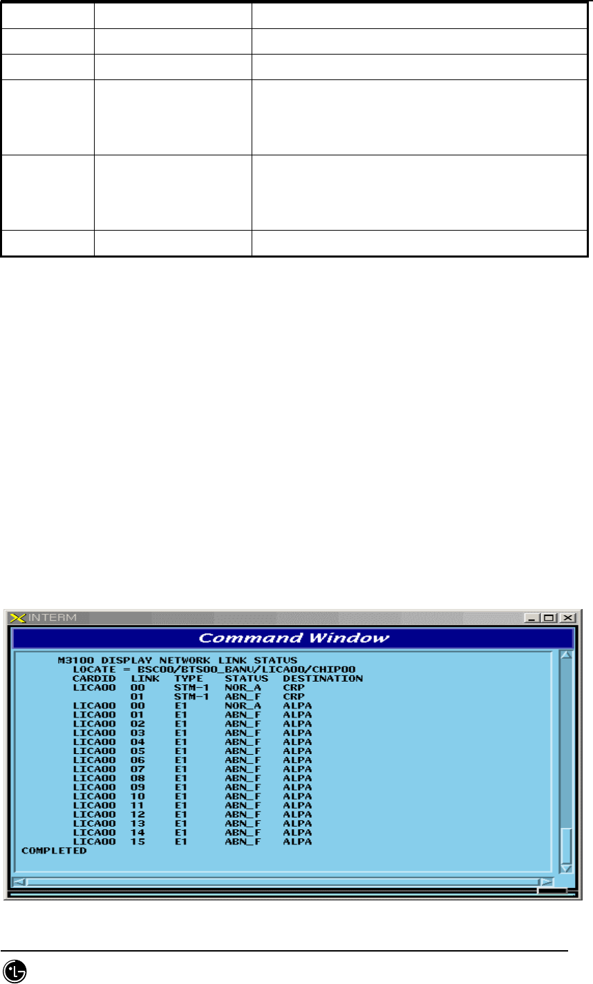
STAREX-IS BSM Manual
Page:386(877)
Issue:1.
0
SMD-011-PMA210
ABN_D Abnormal Deletion card is removed
ABN_F Abnormal Fault Local Fault occurred
ABN_M Abnormal MMC Block Blocked Status by User’s MMC
INIT Initial
Even equipped to PLD, a processor managing the
corresponding device does not normally operate
until now
AB_OB Abnormal Online Block
Based on judgment that a normal call is
impossible due to faults in other devices, the
corresponding device is blocked
N_EQP Not Equipped Card Type is not defined in PLD
4.4.2.1. Network Status Display Command
Function to display the BSS Network status.
Command : DIS-NET-STS: [BSC=a],[BTS=b],SHELF=c,CARD=d,ID=e,[CHIP=f];
a : BSC Number
b : BTS Number
c : SHELF NAME(CAMU,CAMDU,ASMU,ALSU,BANU)
d : CARD NAME(ASCA,ASIA,AOTA,ATSA,ALMA,LICA)
e : CARD ID(0~3)
f : CHIP Number(0~1)
Input : DIS-NET-STS:BSC=0,BTS=0,SHELF=BANU,CARD=LICA,ID=0;
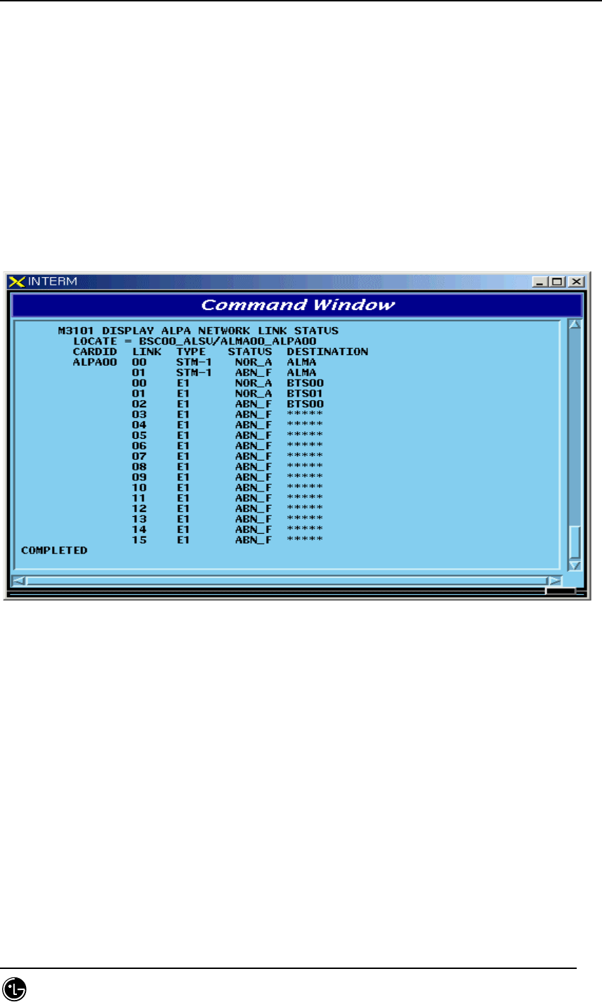
STAREX-IS BSM Manual
Page:387(877)
Issue:1.
0
SMD-011-PMA210
Fig. 4.4-9 Result of Network Status Display Command
4.4.2.2. ALPA Network Status Display
Function to display the ALPA Network status.
Command : DIS-ALPA-STS:BSC=a,ALMA=b,ALPA=c;
a : BSC Number(0~11)
b : ALMA ID(0~1)
c : ALPA ID(0~4)
Input : DIS-ALPA-STS:BSC=0,ALMA=0,ALPA=0;
Fig. 4.4-10 Result of ALPA Network Status Display
4.4.2.3. PDSN NODE Status Display
Function to display the PDSN NODE Network status
Command : DIS-PDSN-STS:SHELF=a,PIP=b;
a: SHELF(PCP(00~02),PMP(00~02))
b: PIP(0~10)
Input : DIS-PDSN-STS:SHELF=PCP00,PIP=0;
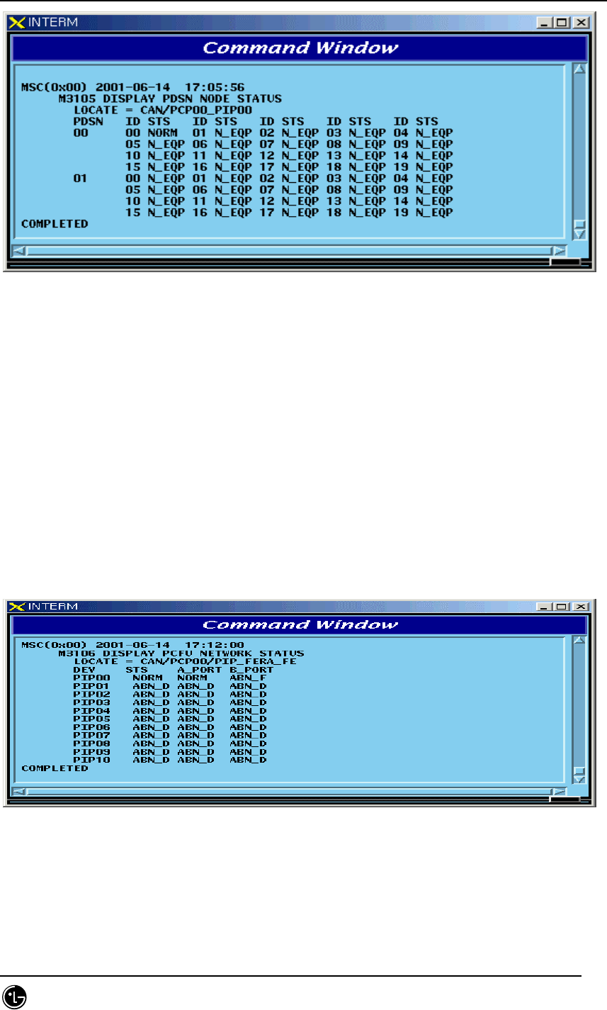
STAREX-IS BSM Manual
Page:388(877)
Issue:1.
0
SMD-011-PMA210
Fig. 4.4-11 Result of PDSN NODE Status Display
4.4.2.4. PCFU Network Status Display Command
Function to display the PCFU Network Status
Command : DIS-PCF-NET:PROC=a,TYPE=b;
a: PCP(00~02),PMP(00~02)
b: PIP_FERA,FETA_PDSN
Input : DIS-PCF-NET:PROC=PCP00,TYPE=PIP_FERA;
Fig. 4.4-12 Result of PCFU Network Status Display Command
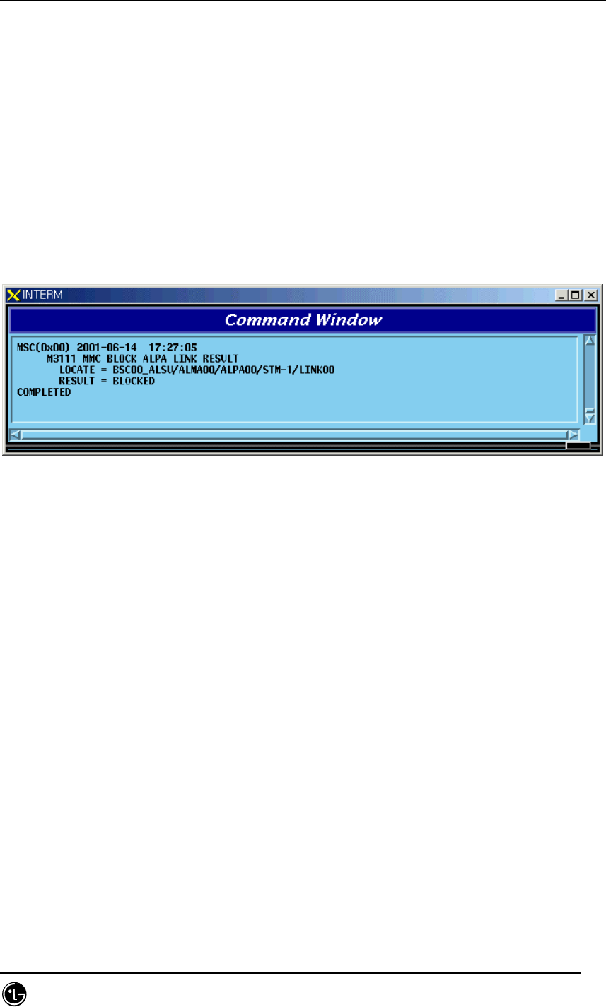
STAREX-IS BSM Manual
Page:389(877)
Issue:1.
0
SMD-011-PMA210
4.4.2.5. ALPA Network Block Command
Function to block the ALPA Network.
Command : BLK-ALPA:BSC=a,ALMA=b,ALPA=c,[TYPE=d],[LINK=e];
a: BSC Number(00~11)
b: ALMA ID(0~1)
c: ALPA ID(0~4)
d: TYPE(STM_1,E1)
e: LINK(0~15)
Input : BLK-ALPA:BSC=0,ALMA=0,ALPA=0,TYPE=STM_1,LINK=0;
Fig. 4.4-13 Result of ALPA Network Block Command
4.4.2.6. UNBlock Command
Function to unblock the ALPA Network.
Command : UBLK-ALPA:BSC=a,ALMA=b,ALPA=c,[TYPE=d],[LINK=e];
a: BSC Number(00~11)
b: ALMA ID(0~1)
c: ALPA ID(0~4)
d: TYPE(STM_1,E1)
e: LINK(0~15)
Input : UBLK-ALPA:BSC=0,ALMA=0,ALPA=0,TYPE=STM_1,LINK=0;
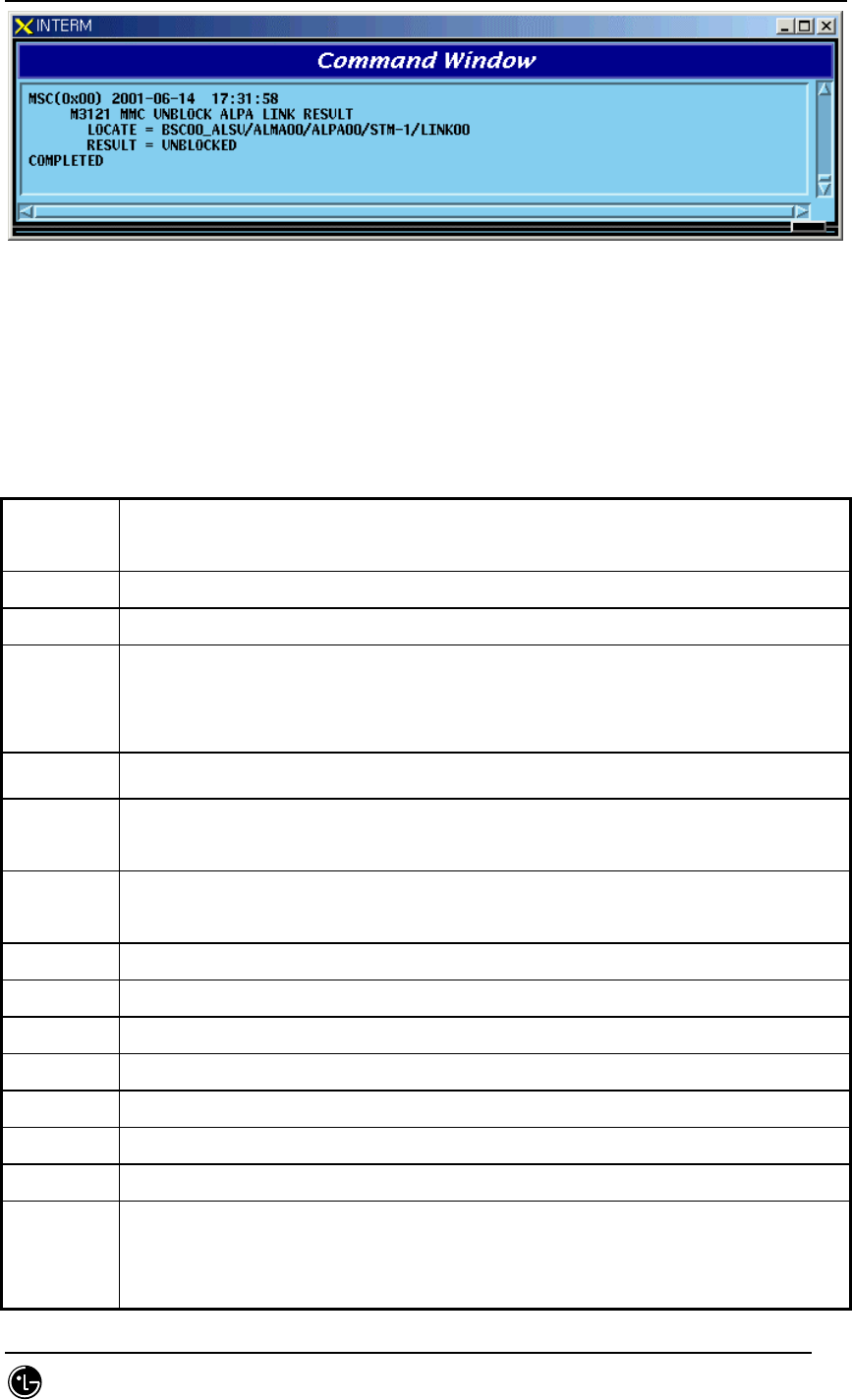
STAREX-IS BSM Manual
Page:390(877)
Issue:1.
0
SMD-011-PMA210
Fig. 4.4-14 Result of ALPA Network UNBlock Command
4.4.3. Can Device Status Control
Table 4.4-3 DEVICE Status List
Status
Types
Definition
NORM Normal
ABN_D Abnormal Deletion (Even equipped to PLD, it is in the Status of Removal)
ABN_F Abnormal Fault(Status that normal operation is impossible due to fault in
Device)
(Test: As a result of DSP Chip Hardware Test, NOK occurs)
ABN_M Abnormal MMC Block
INIT Initial (Even equipped to PLD, a processor managing the corresponding
device does not operate normally until now)
AB_OB Abnormal Online Block (Based on judgment that a normal call is impossible
due to faults in other devices, the appropriate device is blocked)
IDLE Even if it is normal, call resources are not allocated (CE, VCE)
BUSY normal and call resources are allocated (CE, VCE)
N_EQP Status defined as Not Equipped to PLD
READY Even if not defined in PLD, Device is inserted
UNDEF Status that un-defined status is inserted
ABN_I Status being separated as H/W Reset
ABN_B BER Test Status by User
NOR_PB In case that call exists when CHC, Chip is blocked, it indicates the status that
awaits until a call is terminated
it indicates, the Status that waits for the call termination in order to perform

STAREX-IS BSM Manual
Page:391(877)
Issue:1.
0
SMD-011-PMA210
the Vocoder test.
REDNCY In duplicated Device, it indicates Redundancy Status of Standby side(FETA
Only)
CB_OPN For device that is managed only as fault, it is the case that is opened to Fault
Cable
CLK_F During Vocoder Channel test, as a result of Timing-Module test, NOK
occurred (Test Only)
TSW_F As a result of TSLU Loopback test, NOK is occurred (Test Only)
ABN_AT Status in which Vocoder is put to Automatic(Online) test (Test Only)
ABN_MT Status in which Vocoder Manual(Ondemand) is put to test (Test Only)
QAT0_F As a result of QCELP Algorithm test during Vocoder channel test, NOK
occurred in State 0 (Test Only)
QAT1_F As a result of QCELP Algorithm test during Vocoder channel test, NOK
occurred in State 1 (Test Only))
QAT2_F As a result of QCELP Algorithm test during Vocoder channel test, NOK
occurred in State 2 (Test Only)
QAT3_F As a result of QCELP Algorithm test during Vocoder channel test, NOK
occurred in State 3 (Test Only)
VPLB_F As a result of VCPA Loopback test during Vocoder channel test, NOK
occurred (Test Only)
VMLB_F As a result of VCMA Loopback test during Vocoder channel test, NOK
occurred (Test Only)
VLLB_F As a result of VLIA Loopback test during Vocoder channel test, NOK occurred
(Test Only)
4.4.3.1. CAN Device Status Display Command
Function to display Device(BOARD) Status mounted to CAN
Command : DIS-CAN-DEV:PROC=a;
a : CNP,PNP,PCP(00~02)
Input : DIS-CAN-DEV:PROC=CNP;
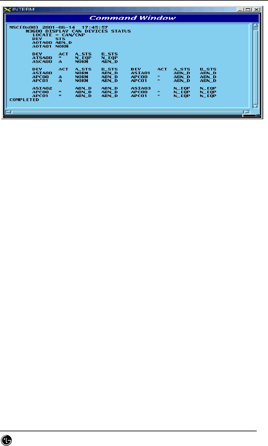
STAREX-IS BSM Manual
Page:392(877)
Issue:1.
0
SMD-011-PMA210
Fig. 4.4-15 Result of CAN Device Status Display Command
4.4.3.2. GPS(CAN) Status Display Command
Function to display Device and Information of CAN GPS.
Command : DIS-GPS-STS:TYPE=a;
a : ALL,GPS_DEV,GPS_INFO
Input : DIS-GPS-STS:TYPE=ALL;
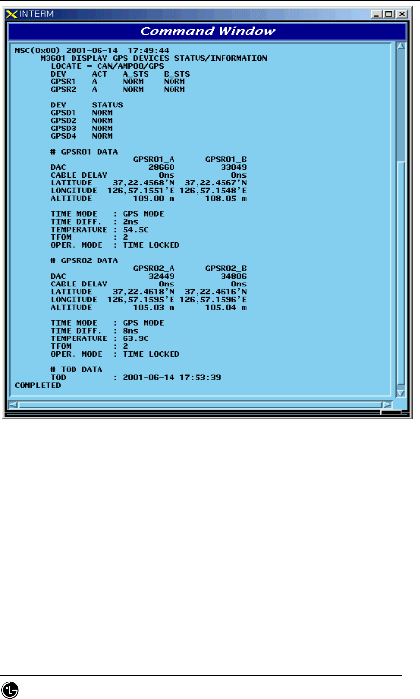
STAREX-IS BSM Manual
Page:393(877)
Issue:1.
0
SMD-011-PMA210
Fig. 4.4-16 Result of GPS(CAN) Status Display Command
4.4.3.3. H/W RESET CAN DEVICE Command
Function to reset CAN Device on H/W Level
Command : RMT-CAN-DEV:PROC=a,DEV=b,ID=c,[SIDE=d],CLS=e;
a: Processor :CNP,PNP,PCP(00~02),PMP(00~02)
b: Device Name: ASCA,ASIA,AOTA,ATSA,PIP,FERA,FETA,BCRA
c: Device ID : 0~10
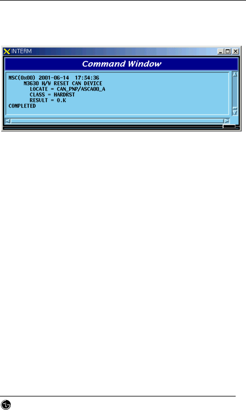
STAREX-IS BSM Manual
Page:394(877)
Issue:1.
0
SMD-011-PMA210
d: SIDE:A_SIDE,B_SIDE
e: CLASS : HARDRST,ISOLAT,UNISOL
Input : RMT-CAN-DEV:PROC=PNP,DEV=ASCA,ID=0,SIDE=A_SIDE,CLS=HARDRST;
Fig. 4.4-17 Result of H/W RESET CAN DEVICE Command
4.4.4. BSC Device Status Control
4.4.4.1. BSC Device Status Display Command
Function to display Status of various Boards mounted to BSC
Command : DIS-BSC-DEV:BSC=a,PROC=b;
a : BSC Number(00~11)
b : PROC Name(NCP,SCP,ALP,SMP(00~04),VMP(00~08))
Input : DIS-BSC-DEV:BSC=1,PROC=NCP;
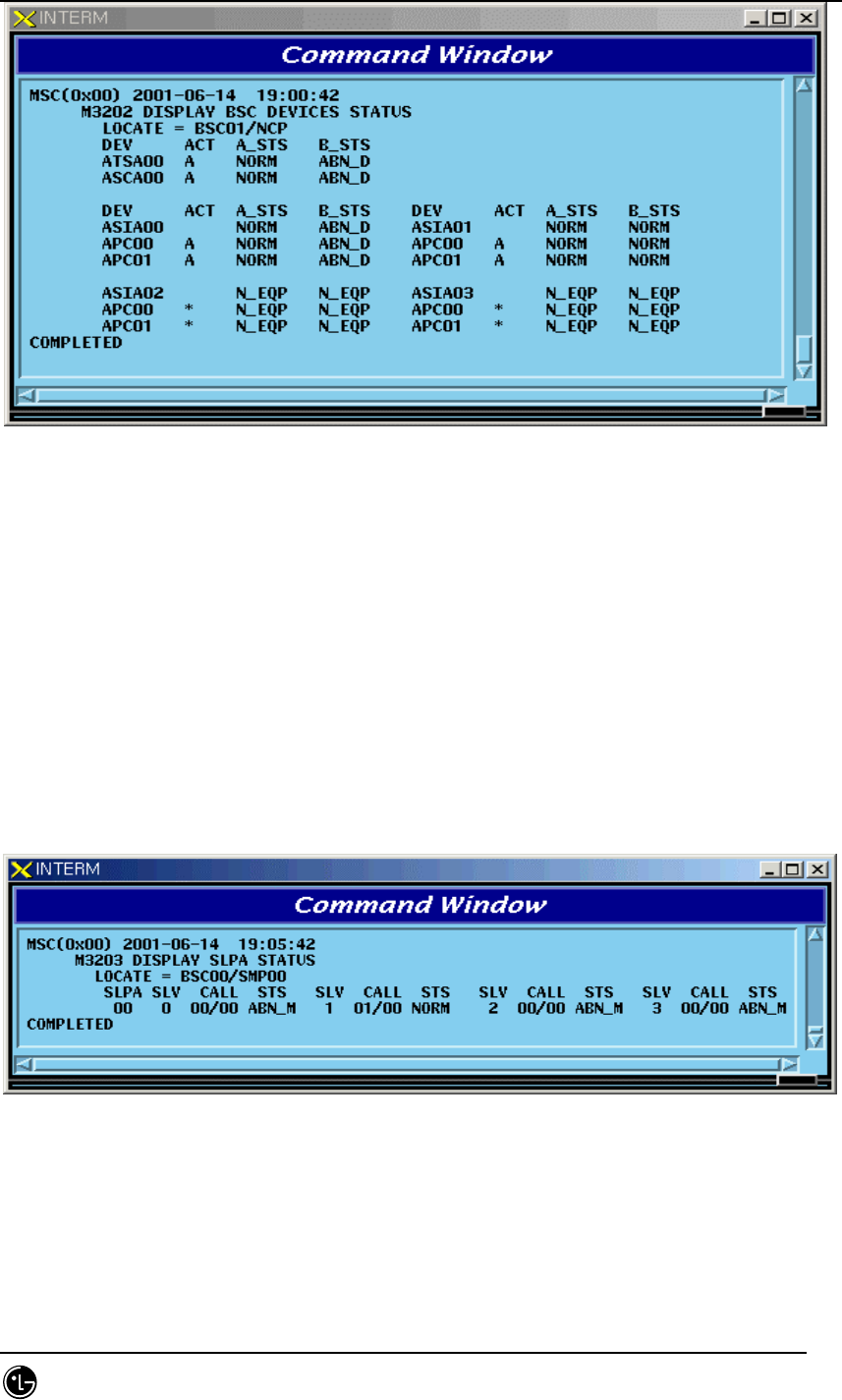
STAREX-IS BSM Manual
Page:395(877)
Issue:1.
0
SMD-011-PMA210
Fig. 4.4-18 Result of BSC Device Status Display
4.4.4.2. SLPA Status Display Command
Function to display the SLPA Status
Command : DIS-SLPA-STS:BSC=a,SMP=b,[SLPA=c];
a : BSC Number(00~11)
b : SMP Number(00~04)
c : SLPA Number(00~17)
Input : DIS-SLPA-STS:BSC=0,SMP=0,SLPA=0;
Fig. 4.4-19 Result of SLPA Status Display Command
4.4.4.3. VCPA Status Display Command
Function to display the VCPA Status
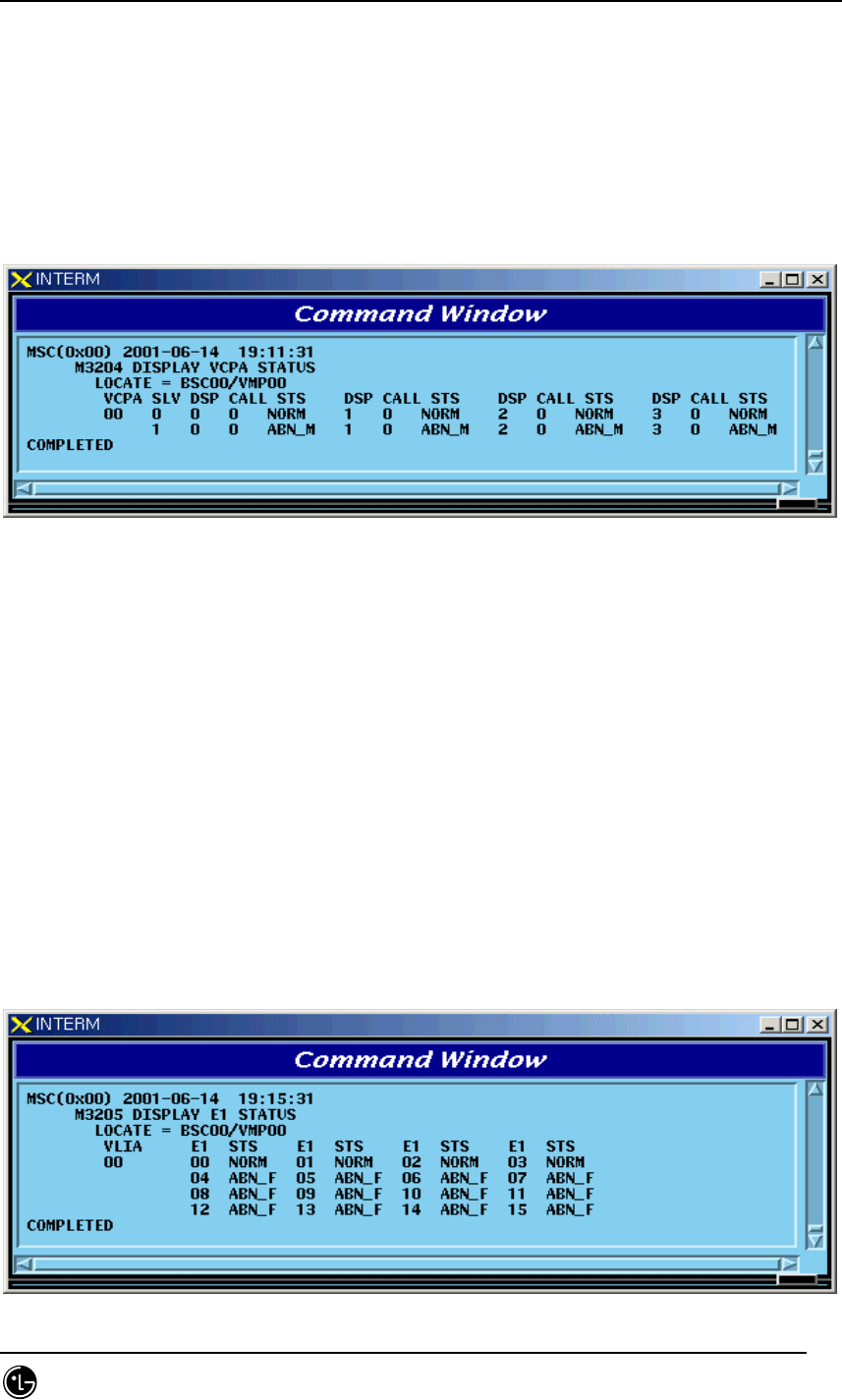
STAREX-IS BSM Manual
Page:396(877)
Issue:1.
0
SMD-011-PMA210
Command : DIS-VCPA-STS:BSC=a,VMP=b,[VCPA=c];
a : BSC Number(00~11)
b : VMP Number(00~07)
c : VCPA Number(00~15)
Input : DIS-VCPA-STS:BSC=0,VMP=0,VCPA=0;
Fig. 4.4-20 Result of VCPA Status Display Command
4.4.4.4. E1 LINK Status Display Command
Function to display E1 Link Status of VLIA
Command : DIS-E1-STS:BSC=a,VMP=b,[VLIA=c];
a : BSC Number(00~11)
b: VMP Number(00~07)
c: VLIA Number(00~01)
Input : DIS-E1-STS:BSC=0,VMP=0,VLIA=0;
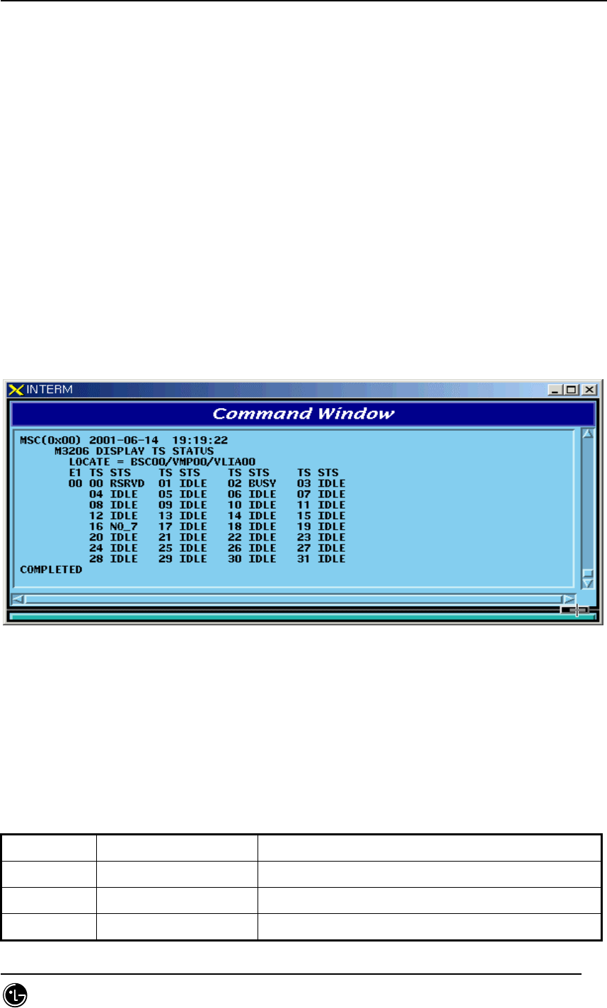
STAREX-IS BSM Manual
Page:397(877)
Issue:1.
0
SMD-011-PMA210
Fig. 4.4-21 Result of E1 LINK Status Display Command
4.4.4.5. TS Network LINK Status Display Command
Function to display the Status of TS Network Link of VLIA.
Command : DIS-TS-STS:BSC=a,VMP=b,VLIA=c,E1=d;
a : BSC Number(00~11)
b : VMP Number(00~07)
c : VLIA Number(00~15)
d : E1 Number(00~15)
Input : DIS-TS-STS:BSC=0,VMP=0,VLIA=0,E1=0;
Fig. 4.4-22 Result of TS Network LINK Status Display Command
4.4.4.6. VCE(Vocoder Channel Element) Status Display Command
Table 4.4-4 Vocoder Channel Element Status LIST
Status Types Definition Description
IDLE Idle Normal status without a Call
8K_Qcelp 8k Qcelp Call 8k QCELP Call Seized Status
8K_EVRC 8k EVRC Call 8k EVRC Call Seized Status
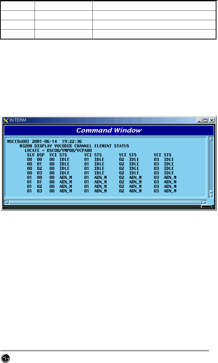
STAREX-IS BSM Manual
Page:398(877)
Issue:1.
0
SMD-011-PMA210
13K_Qcelp 13k Qcelp Call 13k QCELP Call Seized Status
13K_EVRC 13k EVRC Call 13k EVRC Call Seized Status
ABN_M Abnormal MMC Block Blocked Status by user’s MMC
UNDEF Undefined Status Status with Input of undefined Status
Function to display the Channel Element Status of VCE.
Command : DIS-VCE-STS:BSC=a,VMP=b,[VCPA=c];
a : BSC Number(00~11)
b : VMP Number(00~07)
c: VCPA Number(00~15)
Input : DIS-VCE-STS:BSC=0,VMP=0,VCPA=0;
Fig. 4.4-23 Result of VCE(Vocoder Channel Element) Status Display Command
4.4.4.7. SLPA BLOCK Command
Function to block SLPA.
Command : BLK-SLPA:BSC=a,SMP=b,SLPA=c,[SLV=d];
a : BSC Number(00~11)
b : SMP Number(00~04)
c : SLPA Number(00~17)
d : SLV Number(00~03)
Input : BLK-SLPA:BSC=0,SMP=0,SLPA=0,SLV=0;
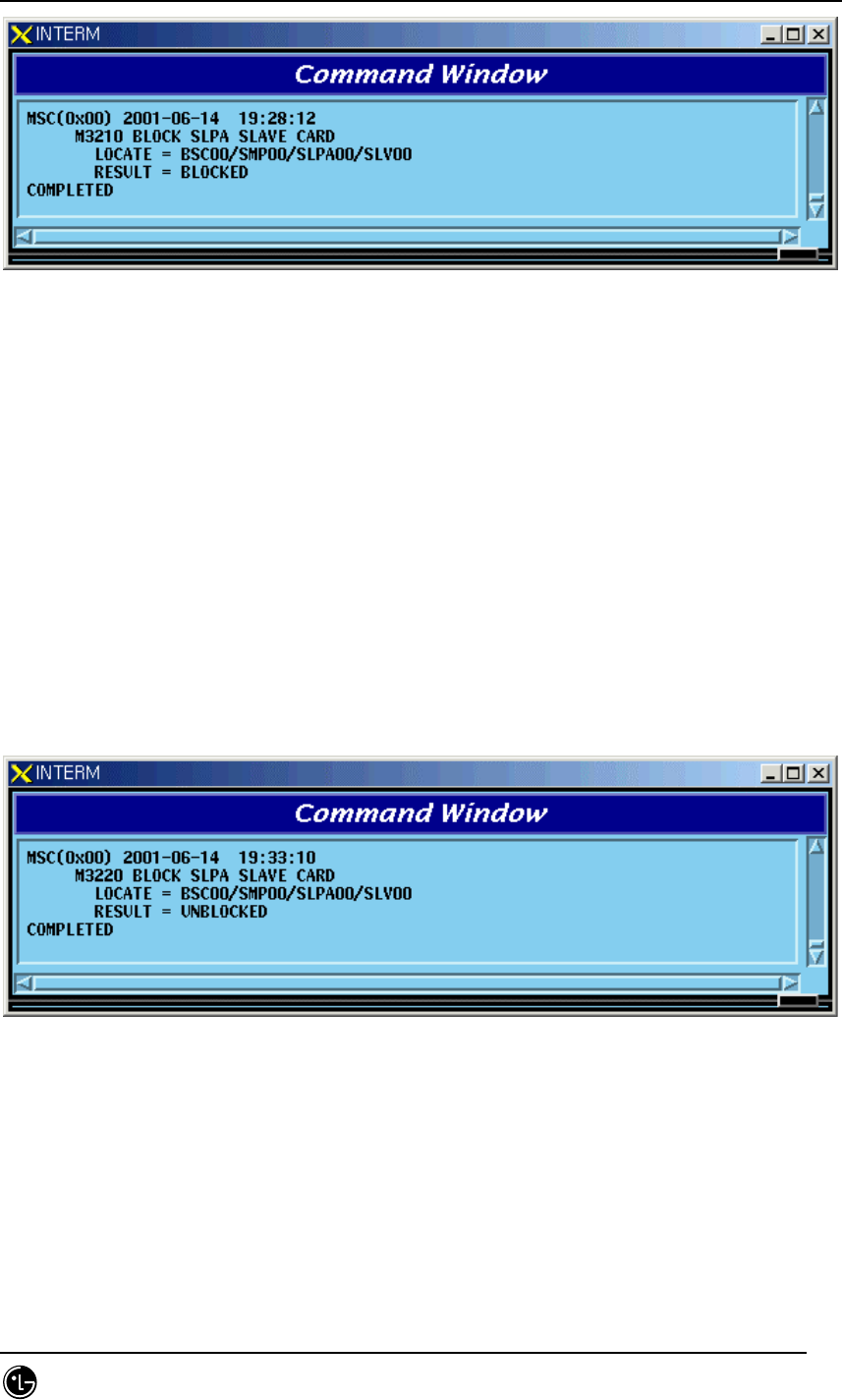
STAREX-IS BSM Manual
Page:399(877)
Issue:1.
0
SMD-011-PMA210
Fig. 4.4-24 Result of SLPA BLOCK Command
4.4.4.8. SLPA UNBLOCK Command
Function to unblock SLPA.
Command : UBLK-SLPA:BSC=a,SMP=b,SLPA=c,[SLV=d];
a : BSC Number(00~11)
b : SMP Number(00~04)
c : SLPA Number(00~17)
d : SLV Number(00~03)
Input : UBLK-SLPA:BSC=0,SMP=0,SLPA=0,SLV=0;
Fig. 4.4-25 Result of SLPA UNBLOCK Command
4.4.4.9. VCPA BLOCK Command
Function to block VCPA.
Command : BLK-VCPA:BSC=a,VMP=b,VCPA=c,[SLV=d],[DSP=e];
a : BSC Number(00~11)