LG Electronics USA 3G1XINBTS STAREX-IS 1900 Indoor BTS User Manual STAREX IS User s Manual
LG Electronics USA STAREX-IS 1900 Indoor BTS STAREX IS User s Manual
Contents
Users Manual Part G
STAREX-IS BSM Manual
Page:629(877)
Issue:1.
0
SMD-011-PMA210
Fig. 5.1-83 CAN Rack FAN Fail
5.1.1.2. BSC Occurrence Alarm Message
5.1.1.2.1. CCSB
5.1.1.2.1.1. CCP Processor
1) When A-Side of the duplicated CCP is normal and functional problems occur on
the B-Side board
Fig. 5.1-84 CCSB CCP Single Function Fail
2) When functional problems occur on the A-Side after B-Side of the duplicated
CCP has a functional problem
Fig. 5.1-85 CCSB CCP Dual Function Fail
3) When A-Side of the duplicated CCP is normal and B-Side board is removed
STAREX-IS BSM Manual
Page:630(877)
Issue:1.
0
SMD-011-PMA210
Fig. 5.1-86 CCSB CCP Single Board Open Fail
4) When A-Side is removed after B-Side of the duplicated CCP is removed
Fig. 5.1-87 CCSB CCP Dual Board Open Fail
5.1.1.2.1.2. SCP Processor
1) When A-Side of the duplicated SCP is normal and functional problems occur on
the B-Side board
Fig. 5.1-88 CCSB SCP Single Function Fail
2) When functional problems occur on the A-Side after B-Side of the duplicated
SCP has a functional problem
STAREX-IS BSM Manual
Page:631(877)
Issue:1.
0
SMD-011-PMA210
Fig. 5.1-89 CCSB SCP Dual Function Fail
3) When A-Side of the duplicated SCP is normal and B-Side board is removed
Fig. 5.1-90 CCSB SCP Single Board Open Fail
4) When A-Side is removed entire B-Side of the duplicated SCP is removed
Fig. 5.1-91 CCSB SCP Dual Board Open Fail
5.1.1.2.1.3. STIA Board
1) When functional faults occur on STIA board

STAREX-IS BSM Manual
Page:632(877)
Issue:1.
0
SMD-011-PMA210
Fig. 5.1-92 CCSB STIA Function Fail
2) When STIA board is removed
Fig. 5.1-93 CCSB STIA Board Open Fail
5.1.1.2.1.4. PRI Board
1) When A-Side of the duplicated PRI is normal and functional problems occur on
the B-Side board
Fig. 5.1-94 CCSB PRI Single Power Fail
2) When functional problems occur on the A-Side after B-Side of the duplicated
PRI has a functional problem
STAREX-IS BSM Manual
Page:633(877)
Issue:1.
0
SMD-011-PMA210
Fig. 5.1-95 CCSB PRI Dual Power Fail
3) When A-Side of the duplicated PRI is normal and B-Side board is removed
Fig. 5.1-96 CCSB PRI Single Power Open Fail
4) When A-Side is removed after B-Side of the duplicated PRI is removed
Fig. 5.1-97 CCSB PRI Dual Power Open Fail
5.1.1.2.1.5. Others
1) When ABID board is removed

STAREX-IS BSM Manual
Page:634(877)
Issue:1.
0
SMD-011-PMA210
Fig. 5.1-98 CCSB ABID Board Open
2) When CCP does not receive 1pps Clock from GPSD normally
Fig. 5.1-99 CCSB 1PPS Clock Fail
3) When CCP does not receive 10MHz Clock from GPSD normally
Fig. 5.1-100 CCSB 10MHz Clock Fail
4) When faults occur in SubHiway Cable between STIA and VLIA
STAREX-IS BSM Manual
Page:635(877)
Issue:1.
0
SMD-011-PMA210
Fig. 5.1-101 CCSB STIA SHW Link Fail
5) When faults occur in CCBU Alarm Cable
Fig. 5.1-102 CCSB Alarm Cable Open
5.1.1.2.2. ASMB
5.1.1.2.2.1. NCP Processor
1) When A-Side of the duplicated NCP is normal and functional problems occur on
B-Side board
Fig. 5.1-103 ASMB NCP Single Function Fail
2) When functional problems occur on the A-Side after B-Side of the duplicated
NCP has a functional problem
Fig. 5.1-104 ASMB NCP Dual Function Fail
STAREX-IS BSM Manual
Page:636(877)
Issue:1.
0
SMD-011-PMA210
3) When A-Side of the duplicated NCP is normal and B-Side board is removed
Fig. 5.1-105 ASMB NCP Single Board Open Fail
4) When A-Side is removed after B-Side of the duplicated NCP is removed
Fig. 5.1-106 ASMB NCP Dual Board Open Fail
5.1.1.2.2.2. ASCA Board
1) When A-Side of the duplicated ASCA is normal and functional problems occur
on the B-Side board
Fig. 5.1-107 ASMB ASCA Single Function Fail
2) When functional problems occur on the A-Side after B-Side of the duplicated
ASCA has a functional problem

STAREX-IS BSM Manual
Page:637(877)
Issue:1.
0
SMD-011-PMA210
Fig. 5.1-108 ASMB ASCA Dual Function Fail
3) When A-Side of the duplicated ASCA is normal and B-Side board is removed
Fig. 5.1-109 ASMB ASCA Single Board Open Fail
4) When A-Side is removed after B-Side of the duplicated ASCA is removed
Fig. 5.1-110 ASMB ASCA Dual Board Open Fail
5.1.1.2.2.3. ASIA Board
1) When A-Side of the duplicated ASIA is normal and functional problems occur on
the B-Side board

STAREX-IS BSM Manual
Page:638(877)
Issue:1.
0
SMD-011-PMA210
Fig. 5.1-111 ASMB ASIA Single Function Fail
2) When functional problems occur on the A-Side after B-Side of the duplicated
ASIA has a functional problem
Fig. 5.1-112 ASMB ASIA Dual Function Fail
3) When A-Side of the duplicated ASIA is normal and B-Side board is removed
Fig. 5.1-113 ASMB ASIA Single Board Fail
4) When A-Side is removed after B-Side of the duplicated ASIA is removed
STAREX-IS BSM Manual
Page:639(877)
Issue:1.
0
SMD-011-PMA210
Fig. 5.1-114 ASMB ASIA Dual Board Open Fail
5.1.1.2.2.4. ATSA Board
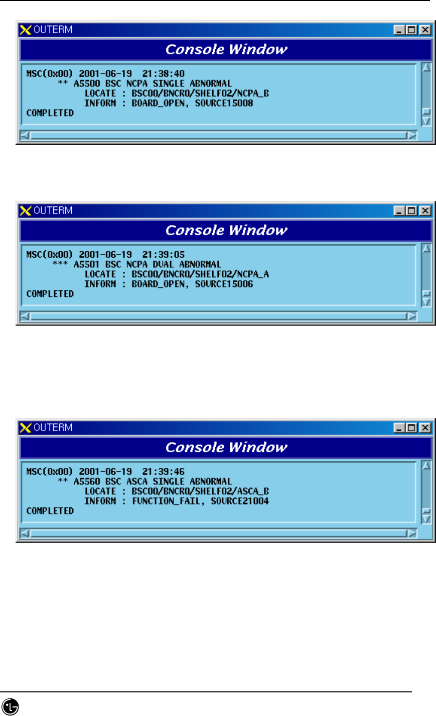
6) When functional problems occur on ATSA board
Fig. 5.1-115 ASMB ATSA Function Fail
7) When ATSA board is removed
Fig. 5.1-116 ASMB ATSA Board Open Fail
5.1.1.2.2.5. PRI Board
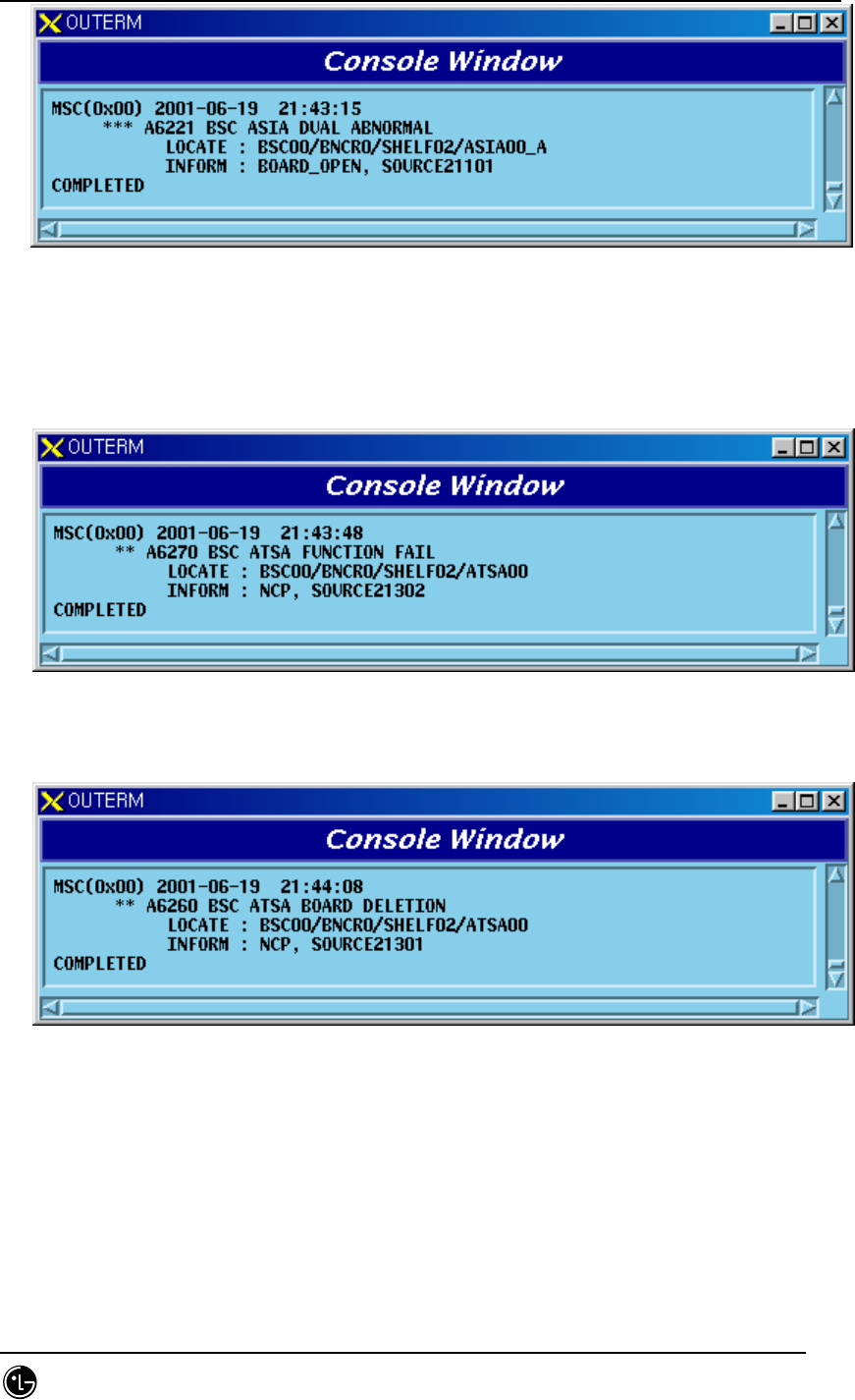
1) When A-Side of the duplicated PRI is normal and functional problems occur on
the B-Side board
STAREX-IS BSM Manual
Page:640(877)
Issue:1.
0
SMD-011-PMA210
Fig. 5.1-117 ASMB PRI Single Power Fail
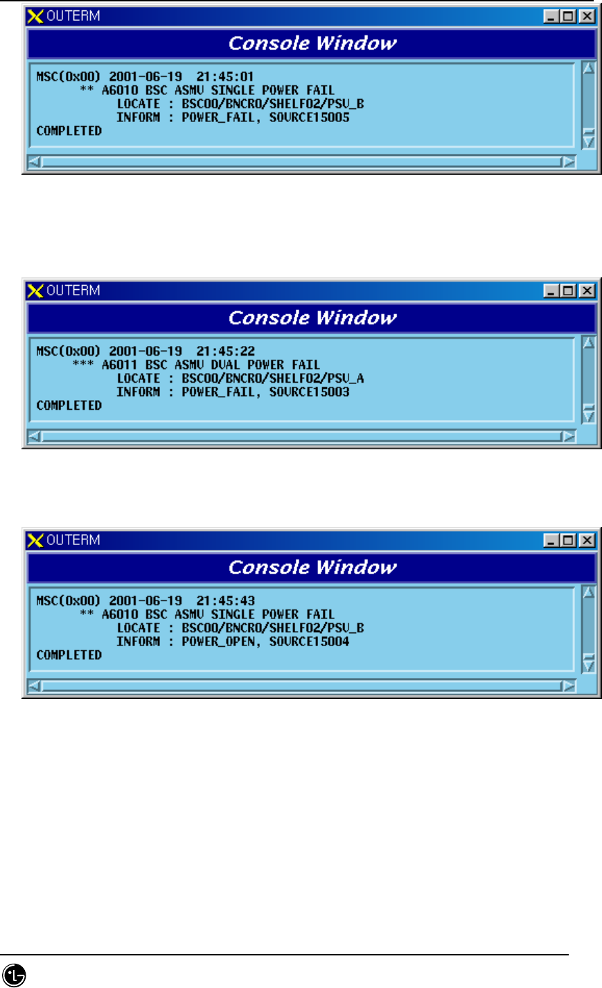
2) When functional problems occur on the A-Side and B-Side of the duplicated PRI
has a functional problem
Fig. 5.1-118 ASMB PRI Dual Power Fail
3) When A-Side of the duplicated PRI is normal and B-Side board is removed
Fig. 5.1-119 ASMB PRI Single Power Open Fail
4) When A-Side is removed after B-Side of the duplicated PRI is removed
STAREX-IS BSM Manual
Page:641(877)
Issue:1.
0
SMD-011-PMA210
Fig. 5.1-120 ASMB PRI Dual Power Open Fail
5.1.1.2.2.6. Others
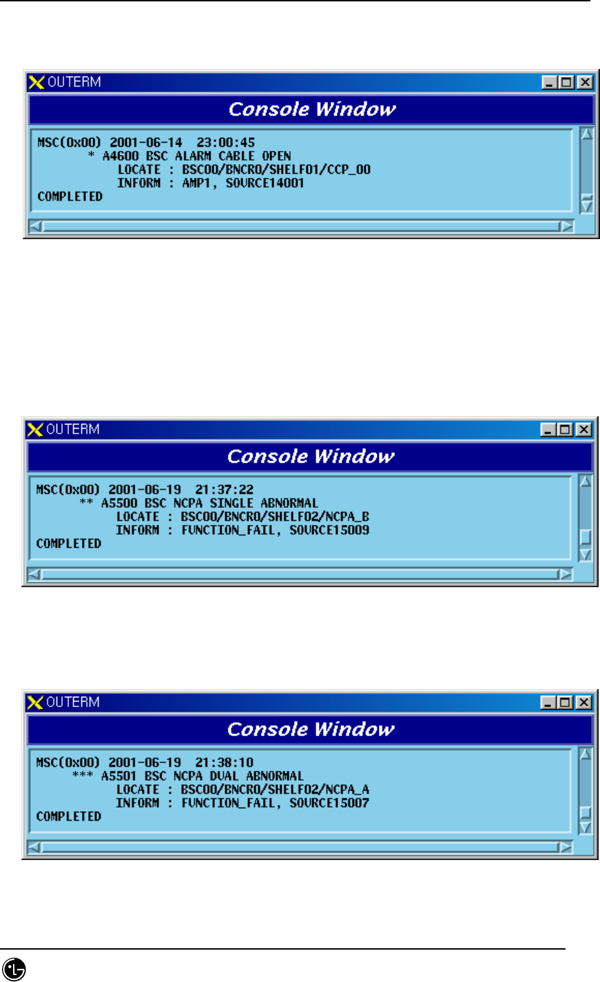
1) When ASMB Alarm Cable opens
Fig. 5.1-121 ASMB Alarm Cable Open
5.1.1.2.3. ALSB
5.1.1.2.3.1. ALP Processor
1) When A-Side of the duplicated ALP is normal and functional problems occur on
the B-Side board
Fig. 5.1-122 ASLB ALP Single Function Fail
2) When functional problems occur on the A-Side after B-Side of the duplicated
ALP has a functional problem
STAREX-IS BSM Manual
Page:642(877)
Issue:1.
0
SMD-011-PMA210
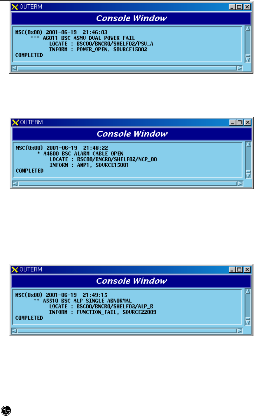
Fig. 5.1-123 ASLB ALP Dual Function Fail
3) When A-Side of the duplicated ALP is normal and B-Side board is removed
Fig. 5.1-124 ASLB ALP Single Board Open Fail
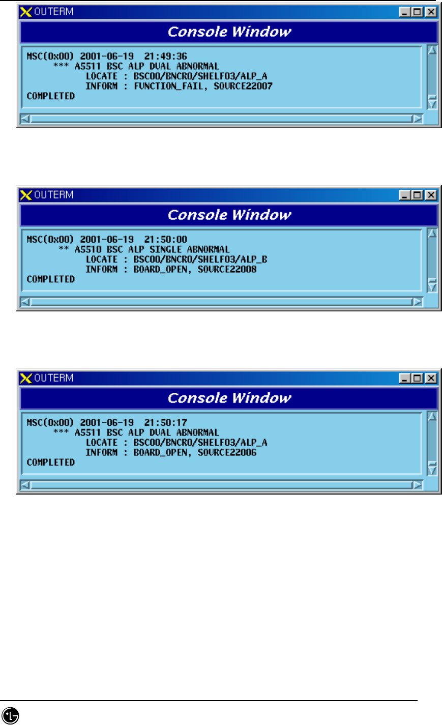
4) When A-Side is removed after B-Side of the duplicated ALP is removed
Fig. 5.1-125 ASLB ALP Dual Board Open Fail
5.1.1.2.3.2. ALMA Board
1) When A-Side of the duplicated ALMA is normal and functional problems occur
on the B-Side board

STAREX-IS BSM Manual
Page:643(877)
Issue:1.
0
SMD-011-PMA210
Fig. 5.1-126 ASLB ALMA Single Function Fail
2) When functional problems occur A-Side after B-Side of the duplicated ALMA
has a functional problem
Fig. 5.1-127 ASLB ALP Dual Function Fail
3) When A-Side of the duplicated ALMA is normal and B-Side board is removed
Fig. 5.1-128 ASLB ALP Single Board Open Fail
4) When A-Side is removed after B-Side of the duplicated ALMA is removed

STAREX-IS BSM Manual
Page:644(877)
Issue:1.
0
SMD-011-PMA210
Fig. 5.1-129 ASLB ALP Dual Board Open Fail
5.1.1.2.3.3. ALPA Board
1) When functional faults occur on ALPA board
Fig. 5.1-130 ASLB ALPA Function Fail
2) When ALPA board is removed
Fig. 5.1-131 ASLB ALPA Board Open Fail
5.1.1.2.3.4. PRI Board
1) When A-Side of the duplicated PRI is normal and functional problems occur on
the B-Side board

STAREX-IS BSM Manual
Page:645(877)
Issue:1.
0
SMD-011-PMA210
Fig. 5.1-132 ASLB PRI Single Power Fail
2) When functional problems occur on the A-Side after B-Side of the duplicated
PRI has a functional problem
Fig. 5.1-133 ASLB PRI Dual Power Fail
3) When A-Side of the duplicated PRI is normal and B-Side board is removed
Fig. 5.1-134 ASLB PRI Single Power Open Fail
4) When A-Side is removed after B–Side of the duplicated PRI is removed

STAREX-IS BSM Manual
Page:646(877)
Issue:1.
0
SMD-011-PMA210
Fig. 5.1-135 ASLB PRI Dual Power Open Fail
5.1.1.2.3.5. Others
1) When ALSB Shelf Alarm Cable is removed
Fig. 5.1-136 ASLB Alarm Cable Open
2) When Loss Of Signal Error occurs in ALPA link
Fig. 5.1-137 ASLB ALPA Link Fail((LOS)
3) When Out Of Frame Error occurs in ALPA link
STAREX-IS BSM Manual
Page:647(877)
Issue:1.
0
SMD-011-PMA210
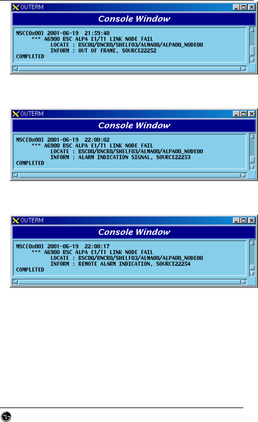
Fig. 5.1-138 ASLB ALPA Link Fail((OOF)
4) When Alarm Indication Signal Error occurs in ALPA link
Fig. 5.1-139 ASLB ALPA Link Fail((AIS)
5) When Remote Alarm Indication Error occurs in ALPA link
Fig. 5.1-140 ASLB ALPA Link Fail((RAI)
5.1.1.2.4. SLB
5.1.1.2.4.1. SMP(SLMA) Processor
1) When functional faults occur on SLMA board

STAREX-IS BSM Manual
Page:648(877)
Issue:1.
0
SMD-011-PMA210
Fig. 5.1-141 SLB SMP Function Fail
2) When SLMA board is removed
Fig. 5.1-142 SLB SMP Board Open Fail
5.1.1.2.4.2. SLPA Board
1) When functional faults occur on SLPA board
Fig. 5.1-143 SLB SLPA Function Fail
2) When SLPA board is removed
STAREX-IS BSM Manual
Page:649(877)
Issue:1.
0
SMD-011-PMA210
Fig. 5.1-144 SLB SLPA Board Open Fail
5.1.1.2.4.3. PRI
1) When functional faults occur on PRI board
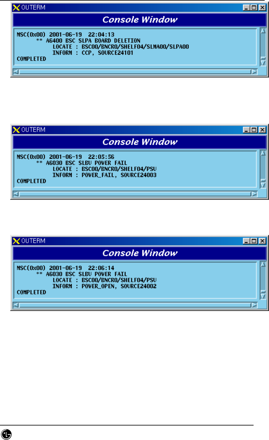
Fig. 5.1-145 SLB PRI Power Fail
2) When PRI board is removed
Fig. 5.1-146 SLB PRI Power Open Fail
5.1.1.2.4.4. Others
1) When SLB Shelf Alarm Cable is removed
STAREX-IS BSM Manual
Page:650(877)
Issue:1.
0
SMD-011-PMA210
Fig. 5.1-147 SLB Alarm Cable Open
2) When Clock Cable is removed from CCP
Fig. 5.1-148 SLB SMP Clock Fail
3) When SAID board is removed
Fig. 5.1-149 SLB SMP SAID Open Fail
5.1.1.2.5. VCB
5.1.1.2.5.1. VMP(VCMA) Processor
1) When functional problems occur on VCMA board

STAREX-IS BSM Manual
Page:651(877)
Issue:1.
0
SMD-011-PMA210
Fig. 5.1-150 VCB VMP Function Fail
2) When VCMA board is removed
Fig. 5.1-151 VCB VMP Board Open Fail
5.1.1.2.5.2. VCPA Board
1) When functional faults occur on VCPA board
Fig. 5.1-152 VCB VCPA Function Fail
2) When VCPA board is removed

STAREX-IS BSM Manual
Page:652(877)
Issue:1.
0
SMD-011-PMA210
Fig. 5.1-153 VCB VCPA Board Open Fail
5.1.1.2.5.3. VLIA Board
1) When a functional board occurs on VLIA board
Fig. 5.1-154 VCB VLIA Function Fail
2) When VLIA board is removed
Fig. 5.1-155 VCB VLIA Board Open Fail
3) When Remote Error occurs in the link between VLIA and MSC

STAREX-IS BSM Manual
Page:653(877)
Issue:1.
0
SMD-011-PMA210
Fig. 5.1-156 VCB VLIA Link Fail(Remote Error)
4) When Local Error occurs in the link between VLIA and MSC
Fig. 5.1-157 VCB VLIA Link Fail(Local Error)
5) When SLIP Error occurs in the link between VLIA and MSC
Fig. 5.1-158 VCB VLIA Link Fail(SLIP Error)
6) When BIT Error occurs in the link between VLIA and MSC
STAREX-IS BSM Manual
Page:654(877)
Issue:1.
0
SMD-011-PMA210
Fig. 5.1-159 VCB VLIA Link Fail(BIT Error)
5.1.1.2.5.4. PRI
1) When functional faults occur on PRI board
Fig. 5.1-160 VCB PRI Power Fail
2) When PRI board is removed
Fig. 5.1-161 VCB PRI Power Open Fail
5.1.1.2.5.5. Others
1) When VCB Shelf Alarm Cable is removed
Fig. 5.1-162 VCB Alarm Cable Open
2) When Clock Cable is removed from CCP
STAREX-IS BSM Manual
Page:655(877)
Issue:1.
0
SMD-011-PMA210
Fig. 5.1-163 VCB VMP Clock Cable Open Fail
3) When SAID board is removed
Fig. 5.1-164 VCB SAID Board Open
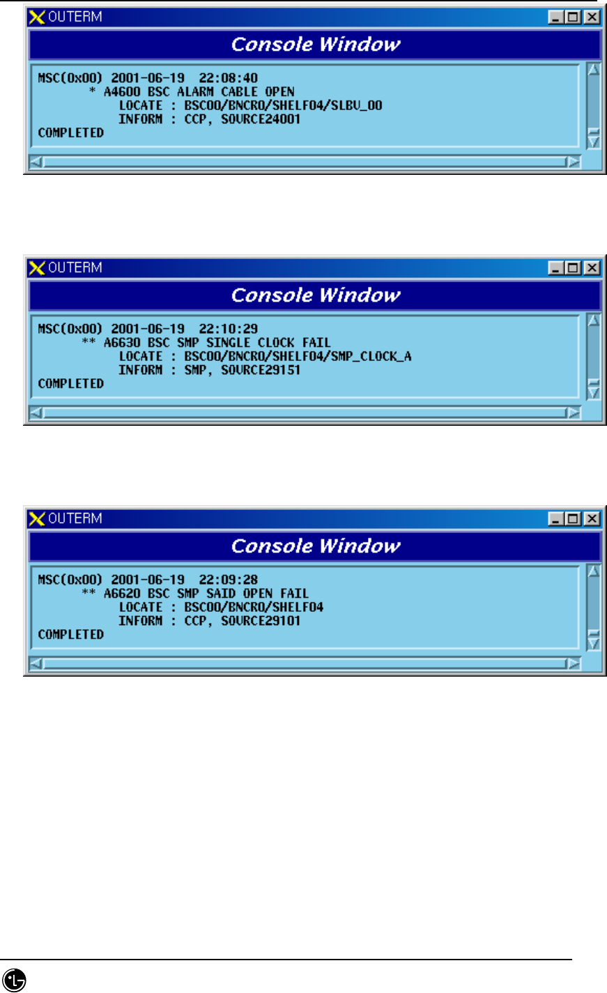
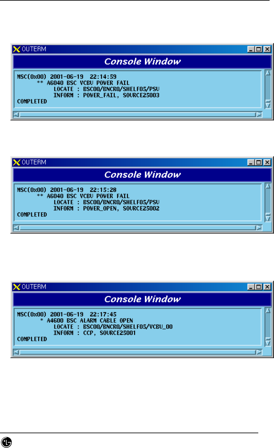
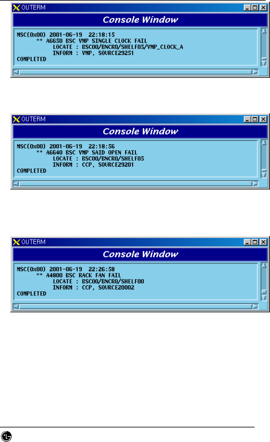
5.1.1.2.6. FAN and Others
1) When a problem occurs in BSC FAN
Fig. 5.1-165 VCB Rack FAN Fail
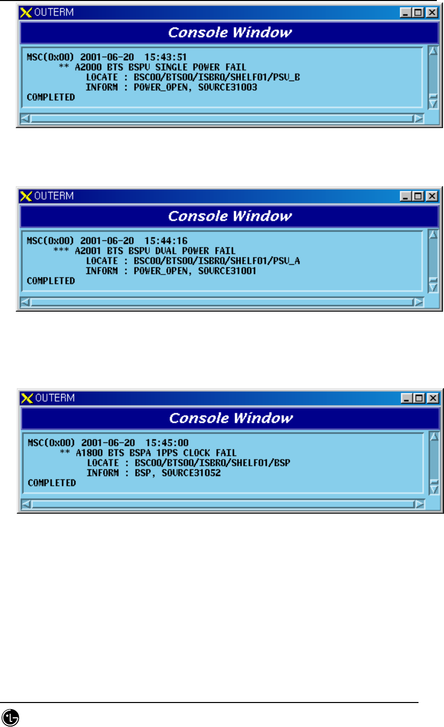
5.1.1.3. BTS Occurrence Alarm Message
5.1.1.3.1. BSPB
5.1.1.3.1.1. BSP Processor
1) When A-Side of the duplicated BSP is normal and functional problems occur on
the B-Side board

STAREX-IS BSM Manual
Page:656(877)
Issue:1.
0
SMD-011-PMA210
Fig. 5.1-166 BSPB BSP Single Function Fail
2) When functional problems occur on the A-Side after B-Side of the duplicated
BSP has a functional problem
Fig. 5.1-167 BSPB BSP Dual Function Fail
3) When A-Side of the duplicated BSP is normal and B-Side board is removed
Fig. 5.1-168 BSPB BSP Single Board Open Fail
4) When A-Side is removed after B-Side of the duplicated BSP is removed

STAREX-IS BSM Manual
Page:657(877)
Issue:1.
0
SMD-011-PMA210
Fig. 5.1-169 BSPB BSP Dual Board Open Fail
5.1.1.3.1.2. PRI within BSPB, BANB Unit
1) When A-Side of the duplicated PRI is normal and functional problems occur on
the B-Side board
Fig. 5.1-170 BSPB PRI Single Power Fail
2) When functional problems occur on the A-Side after B-Side of the duplicated
PRI has a functional problem
Fig. 5.1-171 BSPB PRI Dual Power Fail
3) When A-Side of the duplicated PRI is normal and B –Side board is removed
STAREX-IS BSM Manual
Page:658(877)
Issue:1.
0
SMD-011-PMA210
Fig. 5.1-172 BSPB PRI Single Power Open Fail
4) When A-Side is removed after B-Side of the duplicated PRI is removed
Fig. 5.1-173 BSPB PRI Dual Power Open Fail
5.1.1.3.1.3. Others
1) When BSP does not receive 1pps Clock from GPSD normally
Fig. 5.1-174 BSPB BSP 1PPS Clock Fail
2) When BSP does not receive 10MHz Clock from GPSD normally
STAREX-IS BSM Manual
Page:659(877)
Issue:1.
0
SMD-011-PMA210
Fig. 5.1-175 BSPB BSP 10MHz Clock Fail
5.1.1.3.2. BANB
5.1.1.3.2.1. ARIA Board
1) When functional faults occur on ARIA board
Fig, 5.1-176 BANB ARIA Function Fail
2) When ARIA board is removed
Fig. 5.1-177 BANB ARIA Board Open Fail
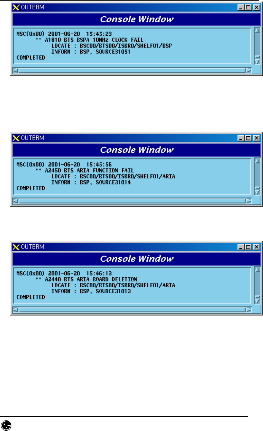
5.1.1.3.2.2. BPPA Board
1) When functional faults occur on BPPA board
STAREX-IS BSM Manual
Page:660(877)
Issue:1.
0
SMD-011-PMA210
Fig. 5.1-178 BANB BPPA Function Fail
2) When BPPA board is removed
Fig. 5.1-179 BANB BPPA Board Open Fail
5.1.1.3.2.3. BCRA Board
1) When A-Side of the duplicated BCRA is normal and functional problems occur
on the B-Side board
Fig. 5.1-180 BANB BCRA Single Function Fail
2) When functional problems occur on the A-Side after B-Side of the duplicated
BCRA has a functional problem

STAREX-IS BSM Manual
Page:661(877)
Issue:1.
0
SMD-011-PMA210
Fig. 5.1-181 BANB BCRA Dual Function Fail
3) When A-Side of the duplicated BCRA is normal and B-Side board is removed
Fig. 5.1-182 BANB BCRA Single Board Open Fail
4) When A-Side is removed after B-Side of the duplicated BCRA is removed.
Fig. 5.1-183 BANB BCRA Dual Board Open Fail
5.1.1.3.2.4. LICA Board
1) When functional faults occur on LICA board

STAREX-IS BSM Manual
Page:662(877)
Issue:1.
0
SMD-011-PMA210
Fig. 5.1-184 BANB LICA Function Fail
2) When LICA board is removed
Fig. 5.1-185 BANB LICA Board Fail
5.1.1.3.3. BSTB
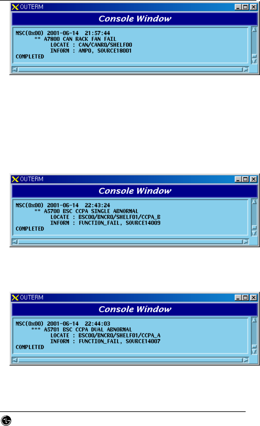
5.1.1.3.3.1. BADA Board
1) When BADA Board Alarm Cable is removed
Fig. 5.1-186 BSTB BADA Alarm Cable Open
2) When a problem occurs in BADA Board power

STAREX-IS BSM Manual
Page:663(877)
Issue:1.
0
SMD-011-PMA210
Fig. 5.1-187 BSTB BADA Power Fail
3) When functional faults occur on BADA board
Fig. 5.1-188 BSTB BADA Function Fail
5.1.1.3.4. RISB
5.1.1.3.4.1. RISA Board
1) When RISA Board Alarm Cable is removed
Fig. 5.1-189 RISB RISA Alarm Cable Open
2) When a problem occurs in RISA board power

STAREX-IS BSM Manual
Page:664(877)
Issue:1.
0
SMD-011-PMA210
Fig. 5.1-190 RISB RISA Power Fail
3) When functional faults occur on RISA board
Fig. 5.1-191 RISB RISA Function Fail
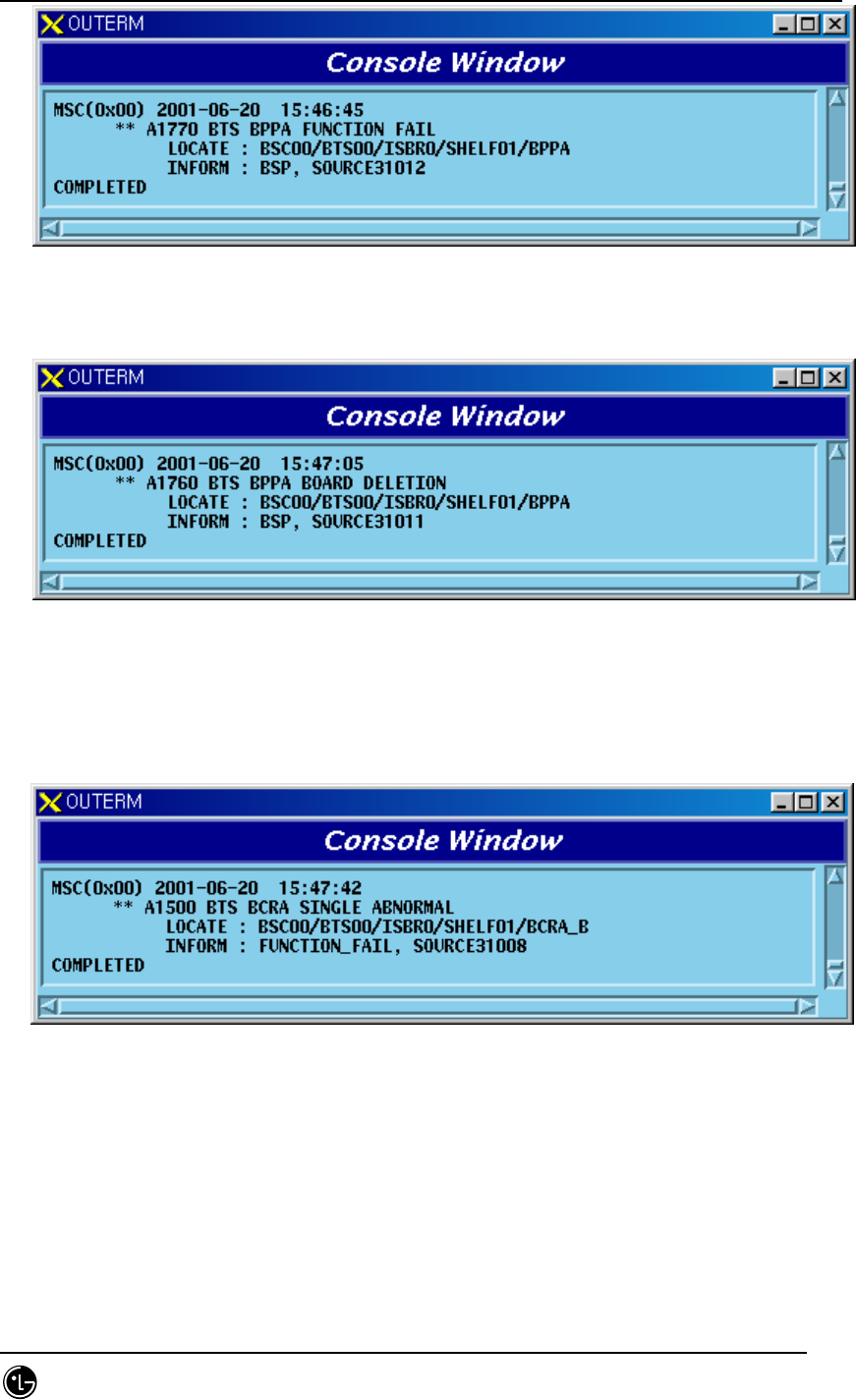
5.1.1.3.5. BOTB
5.1.1.3.5.1. BOTA Board
1) When BOTA Board Alarm Cable is removed
Fig. 5.1-192 BOTB BOTA Alarm Cable Open
2) When a problem occurs in BOTA board power
STAREX-IS BSM Manual
Page:665(877)
Issue:1.
0
SMD-011-PMA210
Fig. 5.1-193 BOTB BOTA Power Fail
3) When functional faults occur on BOTA board
Fig. 5.1-194 BOTB BOTA Board Open Fail
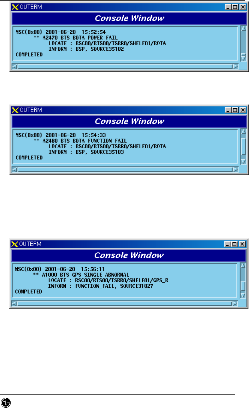
5.1.1.3.6. BTGB
5.1.1.3.6.1. GPS-R Board
1) When A-Side of the duplicated GPSR is normal and functional problems occur
on B –Side board
Fig. 5.1-195 BTGB GPS Single Function Fail
2) When functional problems occur on the A-Side after B-Side of the duplicated
GPSR has a functional problem
STAREX-IS BSM Manual
Page:666(877)
Issue:1.
0
SMD-011-PMA210
Fig. 5.1-196 BTGB GPS Dual Function Fail
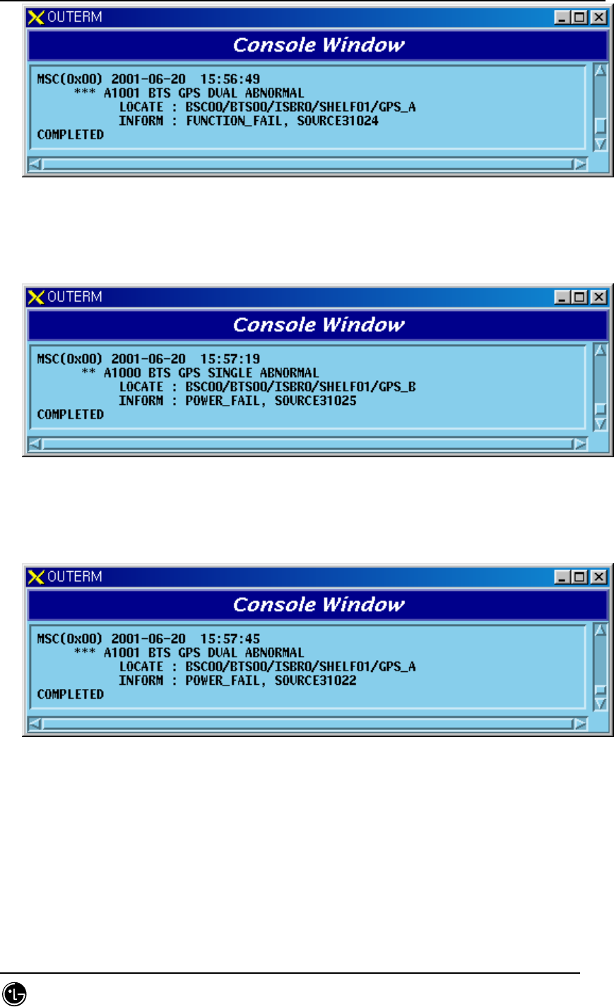
3) When A-Side of the duplicated GPSR is normal and faults occur in B-Side
power
Fig. 5.1-197 BTGB GPS Single Power Fail
4) When a problem occurs in A-Side power after B-Side power of the duplicated
GPSR has a problem
Fig. 5.1-198 BTGB GPS Dual Power Fail
5) When A-Side of the duplicated GPSR is normal and B-Side board is removed
STAREX-IS BSM Manual
Page:667(877)
Issue:1.
0
SMD-011-PMA210
Fig. 5.1-199 BTGB GPS Single Board Open Fail
6) When A-Side is removed after B-Side of the duplicated GPSR is removed
Fig. 5.1-200 BTGB GPS Dual Board Open Fail
7) When GPSR Control Cable is removed
Fig. 5.1-201 BTGB GPS Control Cable Open
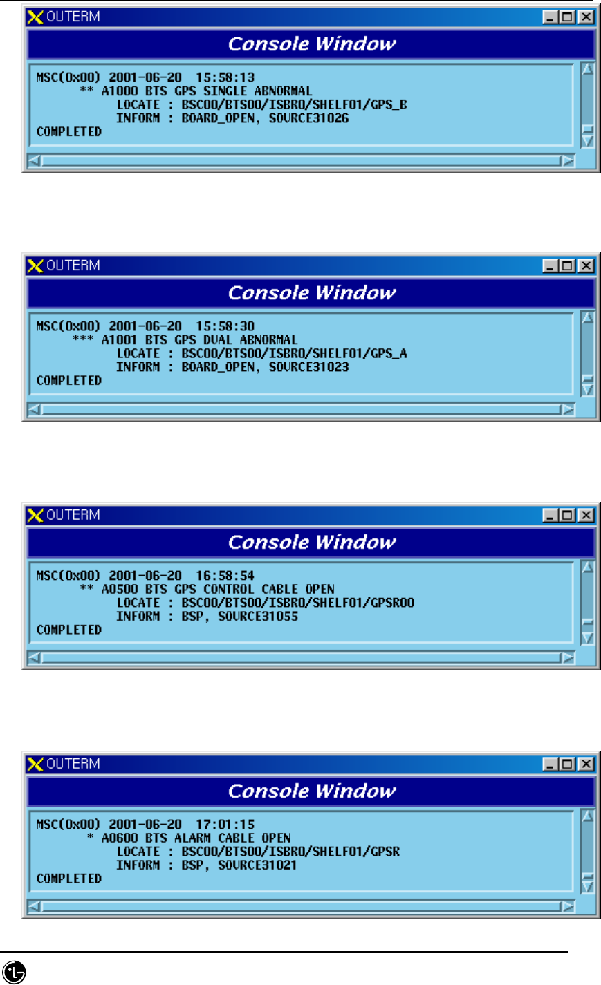
8) When GPSR Alarm Cable is removed
STAREX-IS BSM Manual
Page:668(877)
Issue:1.
0
SMD-011-PMA210
Fig. 5.1-202 BTGB GPS Alarm Cable Open
5.1.1.3.7. DBPB
5.1.1.3.7.1. DBPA Board
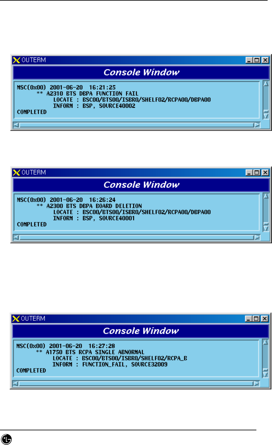
1) When functional faults occur on DBPA board
Fig. 5.1-203 DBPB DBPA Function Fail
2) When DBPA board is removed
Fig. 5.1-204 DBPB DBPA Board Open Fail
5.1.1.3.8. RCCB
5.1.1.3.8.1. RCP Processor
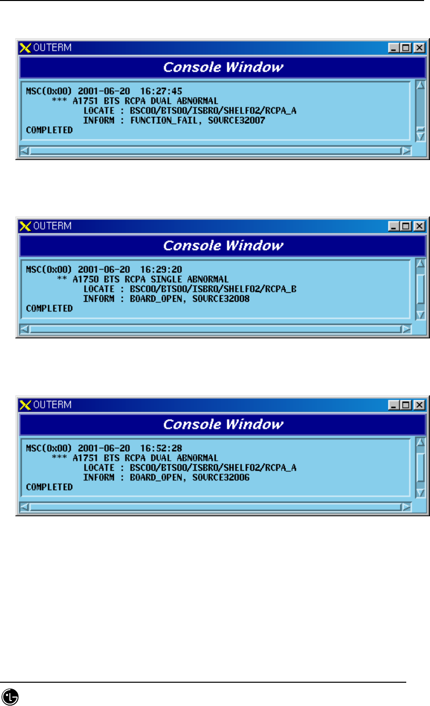
1) When A-Side of the duplicated RCP is normal and functional problems occur on
the B-Side board
Fig. 5.1-205 RCCB RCP Single Function Fail
STAREX-IS BSM Manual
Page:669(877)
Issue:1.
0
SMD-011-PMA210
2) When functional problems occur on the A-Side after B-Side of the duplicated
RCP has a functional problem
Fig. 5.1-206 RCCB RCP Dual Function Fail
3) When A-Side of the duplicated RCP is normal and B-Side board is removed
Fig. 5.1-207 RCCB RCP Single Board Open Fail
4) When A-Side is removed after B-Side of the duplicated RCP is removed
Fig. 5.1-208 RCCB RCP Dual Board Open Fail
5.1.1.3.8.2. BUDA Board
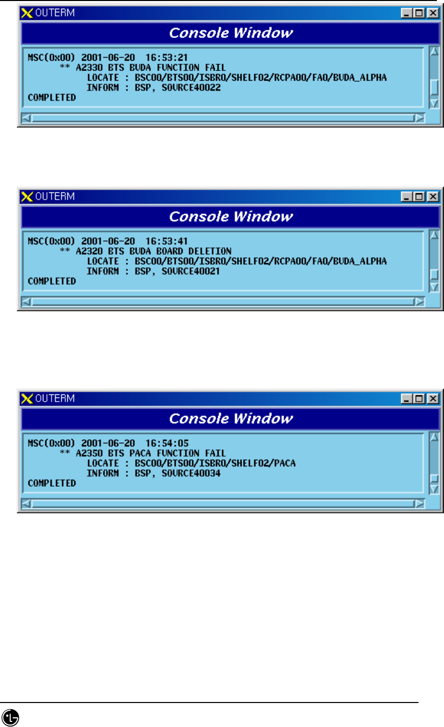
1) When functional faults occur on BUDA board
STAREX-IS BSM Manual
Page:670(877)
Issue:1.
0
SMD-011-PMA210
Fig. 5.1-209 RCCB BUDA Function Fail
2) When BUDA board is removed
Fig. 5.1-210 RCCB BUDA Board Open Fail
5.1.1.3.8.3. PACA Board
1) When functional faults occur on PACA board
Fig. 5.1-211 RCCB PACA Function Fail
2) When PACA board is removed
STAREX-IS BSM Manual
Page:671(877)
Issue:1.
0
SMD-011-PMA210
Fig. 5.1-212 RCCB PACA Board Open Fail
5.1.1.3.8.4. PRI Board for Providing DBPB/RCCB UNIT Power
1) When A-Side of the duplicated PRI is normal and functional problems occur on
the B-Side board
Fig. 5.1-213 DBPB/RCCB PRI Single Power Fail
2) When functional problems occur on the A-Side after B-Side of the duplicated
PRI has a functional problem
Fig. 5.1-214 DBPB/RCCB PRI Dual Power Fail
3) When A-Side of the duplicated PRI is normal and B-Side board is removed
STAREX-IS BSM Manual
Page:672(877)
Issue:1.
0
SMD-011-PMA210
Fig. 5.1-215 DBPB/RCCB PRI Single Power Open Fail
4) When A-Side is removed after B-Side of the duplicated PRI is removed
Fig. 5.1-216 DBPB/RCCB PRI Dual Power Open Fail
5.1.1.3.8.5. Others
1) When DBPB/RCCB UNIT Alarm Cable is removed
Fig. 5.1-217 DBPB/RCCB Alarm Cable Open
5.1.1.3.9. LPAB
5.1.1.3.9.1. LPAU Board
1) When LPAB Alarm Cable is removed
STAREX-IS BSM Manual
Page:673(877)
Issue:1.
0
SMD-011-PMA210
Fig. 5.1-218 LPAB Alarm Cable Open
2) When functional faults occur in LPAB Combiner
Fig. 5.1-219 LPAB LPA Combiner Fail
3) When faults occur in LPAB Combiner FAN
Fig. 5.1-220 LPAB LPA Combiner FAN Fail
4) When LPA board is removed

STAREX-IS BSM Manual
Page:674(877)
Issue:1.
0
SMD-011-PMA210
Fig. 5.1-221 LPAB LPA Board Open Fail
5) When functional faults occur on LPA board
Fig. 5.1-222 LPAB LPA Board Function Fail
6) When DC power of LPA board is unstable
Fig. 5.1-223 LPAB LPA DC/DC Alarm
7) When much RF power is reflected in output end of LPA board
Fig. 5.1-224 LPAB LPA VSWR Alarm
8) When LPA board is disabled

STAREX-IS BSM Manual
Page:675(877)
Issue:1.
0
SMD-011-PMA210
Fig. 5.1-225 LPAB LPA Disable Alarm
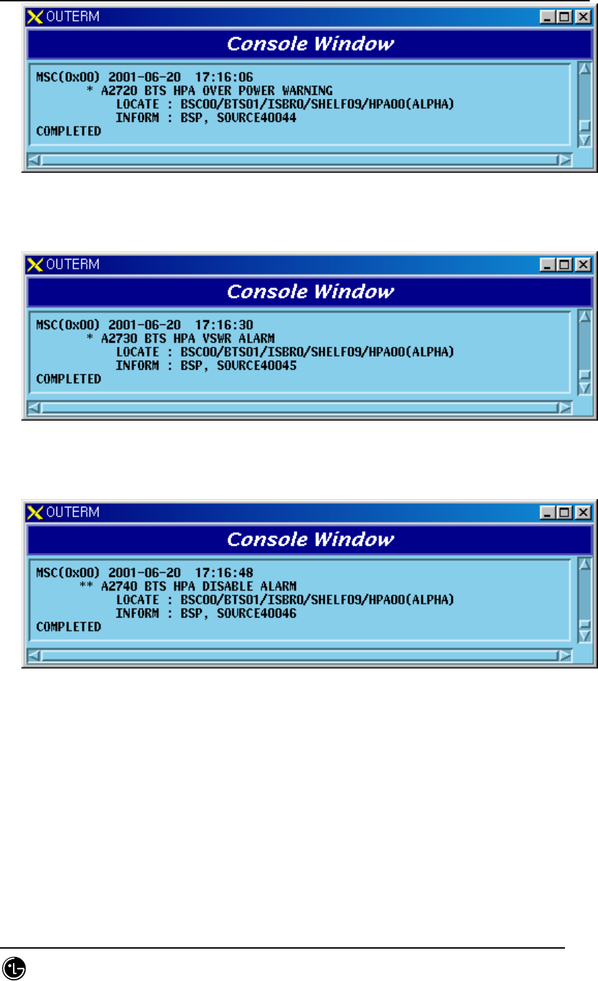
9) When input power level of LPA board is high
Fig. 5.1-226 LPAB LPA Over Power Warning
10) When LPA board temperature is high
Fig. 5.1-227 LPAB LPA Over Temperature Alarm
11) When input Power level of LPA board is high
STAREX-IS BSM Manual
Page:676(877)
Issue:1.
0
SMD-011-PMA210
Fig. 5.1-228 LPAB LPA Over Power Alarm
5.1.1.3.10. HPAB
5.1.1.3.10.1. HPA Board
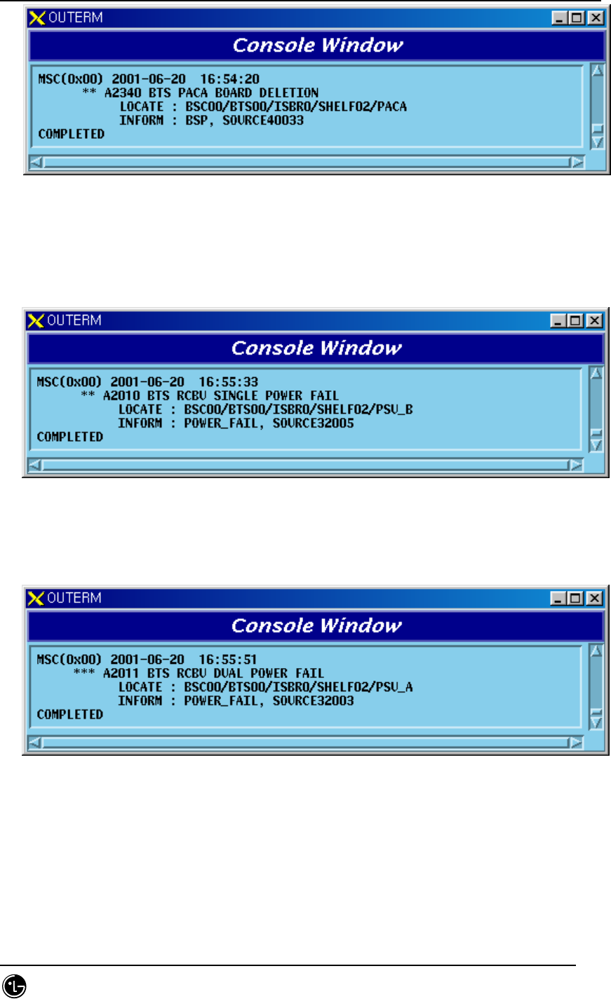
1) When HPAB Alarm Cable is removed
Fig. 5.1-229 HPAB HPA Alarm Cable Open
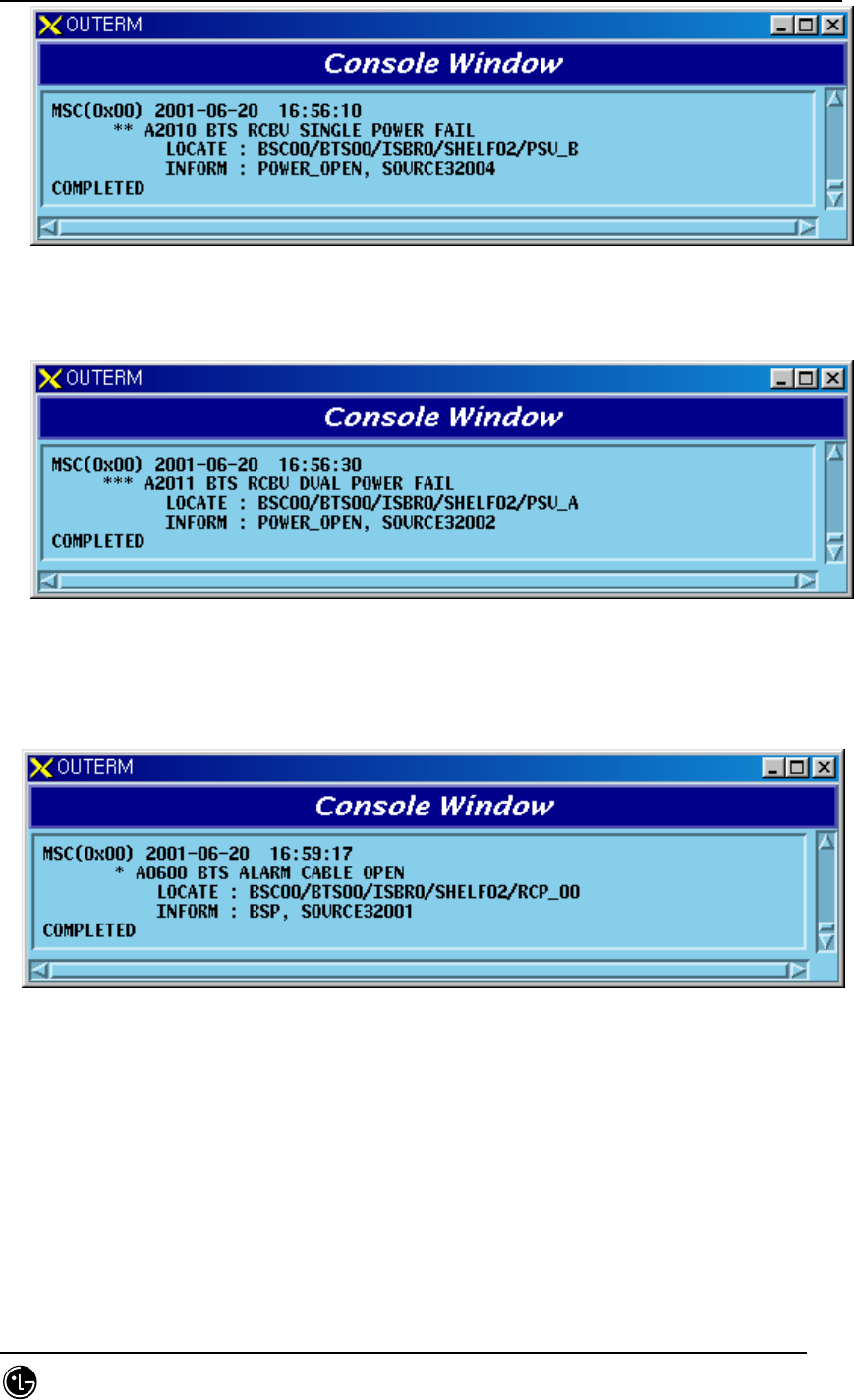
2) When HPA board is removed
Fig. 5.1-230 HPAB HPA Board Open Fail
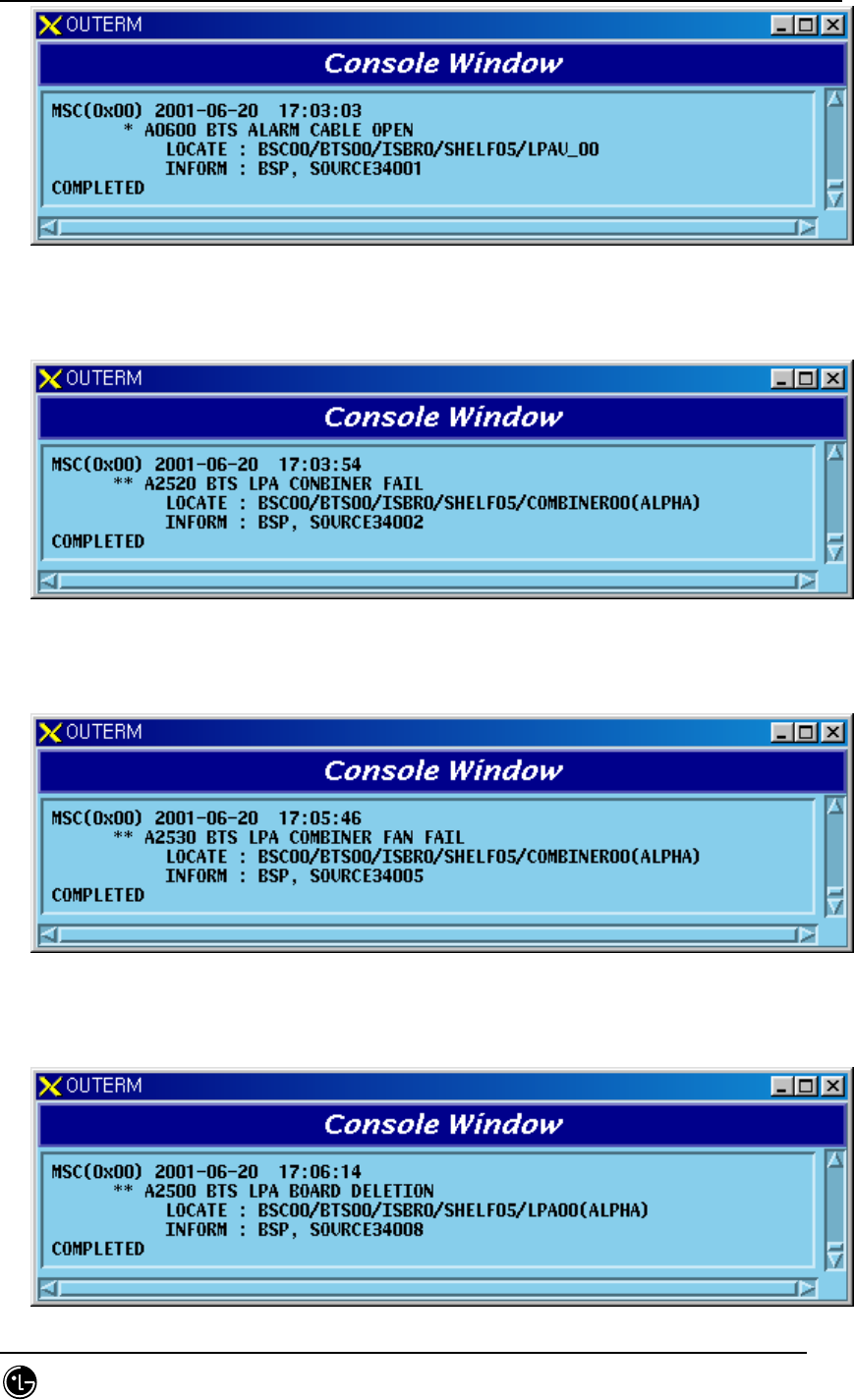
3) When functional faults occur on HPA board
Fig. 5.1-231 HPAB HPA Power Fail
4) When faults occur in HPA Board Power Supply
STAREX-IS BSM Manual
Page:677(877)
Issue:1.
0
SMD-011-PMA210
Fig. 5.1-232 HPAB HPA Power Supply Alarm
5) When much RF power is reflected in HPA output end
Fig. 5.1-233 HPAB HPA VSWR Alarm
6) When HPA board is disabled
Fig. 5.1-234 HPAB HPA Disable Alarm
7) When HPA board temperature is high
Fig. 5.1-235 HPAB HPA Over Temperature Alarm
8) When input Power level of HPA board is high
STAREX-IS BSM Manual
Page:678(877)
Issue:1.
0
SMD-011-PMA210
Fig. 5.1-236 HPAB HPA Over Power Alarm
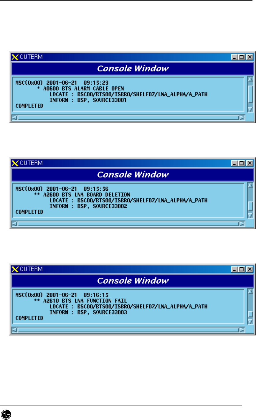
5.1.1.3.11. CFEB
5.1.1.3.11.1. LNA Board
1) When LNA Alarm Cable board is removed
Fig. 5.1-237 CFEB LNA Alarm Cable Open Fail
2) When LNA board is removed
Fig. 5.1-238 CFEB LNA Board Open Fail
3) When functional faults occur on LNA board
Fig. 5.1-239 CFEB LNA Function Fail
5.1.1.3.12. Environment Alarm
1) When outdoor BTS Environment Alarm Cable is removed

STAREX-IS BSM Manual
Page:679(877)
Issue:1.
0
SMD-011-PMA210
Fig. 5.1-240 Outdoor BTS ENV Alarm Cable Open
2) When outdoor BTS Rectifier Alarm Cable is removed
Fig. 5.1-241 Outdoor BTS ENV Rectifier Unit Alarm Cable Open
3) When outdoor BTS Cold Starter fails
Fig. 5.1-242 Outdoor BTS ENV Cold Starter Fail
4) When outdoor BTS Rectifier Unit fails

STAREX-IS BSM Manual
Page:680(877)
Issue:1.
0
SMD-011-PMA210
Fig. 5.1-243 Outdoor BTS ENV Rectifier Unit Fail
5) Outdoor BTS Voltage High Alarm
Fig. 5.1-244 Outdoor BTS ENV Voltage High Alarm
6) Outdoor BTS Voltage Low Alarm
Fig. 5.1-245 Outdoor BTS ENV Voltage Low Alarm
7) When outdoor BTS AC fails
Fig. 5.1-246 Outdoor BTS AC Fail
8) Outdoor BTS Battery Voltage Low Alarm

STAREX-IS BSM Manual
Page:681(877)
Issue:1.
0
SMD-011-PMA210
Fig. 5.1-247 Outdoor BTS ENV Battery Low Voltage Alarm
9) Outdoor BTS Fuse/Relay Loss Alarm
Fig. 5.1-248 Outdoor BTS ENV Fuse/Relay Loss Alarm
10) When outdoor BTS DMC-14 fails
Fig. 5.1-249 Outdoor BTS ENV DMC-14 Fail
11) Outdoor BTS Power Cut Alarm
STAREX-IS BSM Manual
Page:682(877)
Issue:1.
0
SMD-011-PMA210
Fig. 5.1-250 Outdoor BTS ENV Power Cut Alarm
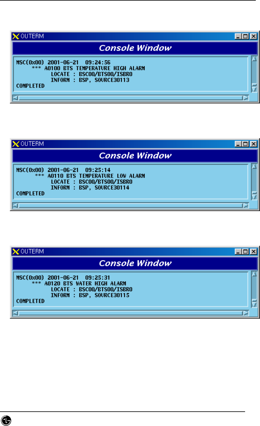
12) Outdoor BTS Temperature High Alarm
Fig. 5.1-251 Outdoor BTS ENV Temperature High Alarm
13) Outdoor BTS Temperature Low Alarm
Fig. 5.1-252 Outdoor BTS ENV Temperature Low Alarm
14) Outdoor BTS Water High Alarm
Fig. 5.1-253 Outdoor BTS ENV Water High Alarm
15) Outdoor BTS Water Low Alarm
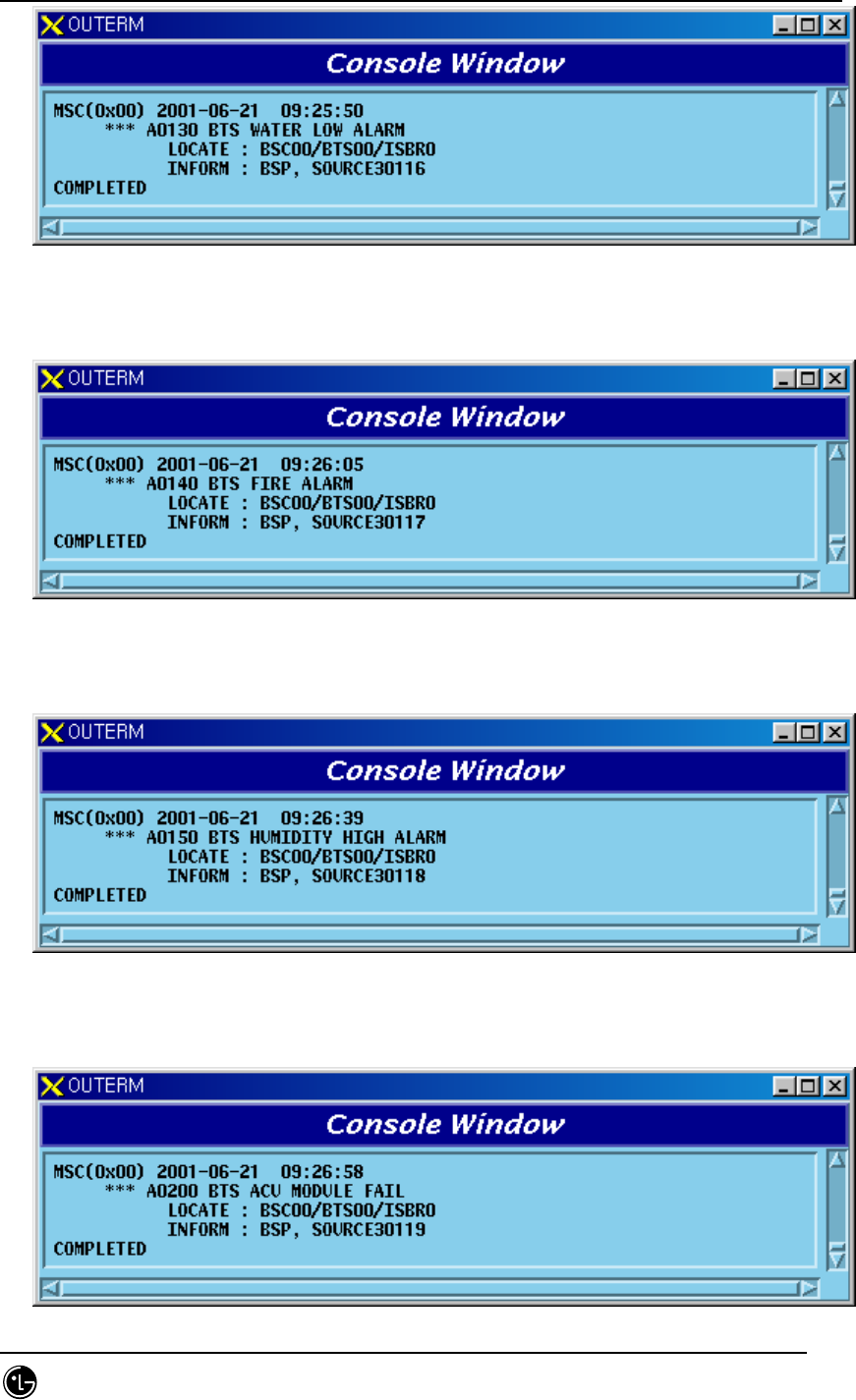
STAREX-IS BSM Manual
Page:683(877)
Issue:1.
0
SMD-011-PMA210
Fig. 5.1-254 Outdoor BTS ENV Water Low Alarm
16) Outdoor BTS Fire Alarm
Fig. 5.1-255 Outdoor BTS ENV Fire Alarm
17) Outdoor BTS Humidity High Alarm
Fig. 5.1-256 Outdoor BTS ENV Humidity High Alarm
18) When outdoor BTS ACU Module fails
STAREX-IS BSM Manual
Page:684(877)
Issue:1.
0
SMD-011-PMA210
Fig. 5.1-257 Outdoor BTS ENV ACU Module Fail
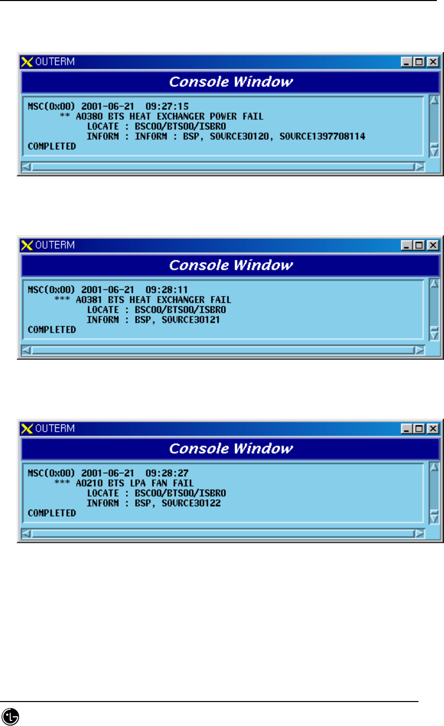
19) When outdoor BTS Heat Exchanger Power fails
Fig. 5.1-258 Outdoor BTS ENV Heat Exchanger Power Fail
20) When outdoor BTS Heat Exchanger fails
Fig. 5.1-259 Outdoor BTS ENV Heat Exchanger Fail
21) When outdoor BTS LPA FAN fails
Fig. 5.1-260 Outdoor BTS ENV LPA FAN Fail
22) When outdoor BTS AC Equipment Heater fails

STAREX-IS BSM Manual
Page:685(877)
Issue:1.
0
SMD-011-PMA210
Fig. 5.1-261 Outdoor BTS ENV AC Equipment Heater Fail
23) Outdoor BTS Front/Rear Door Open Alarm
Fig. 5.1-262 Outdoor BTS ENV Front/Rear Door Open Alarm
24) Outdoor BTS Side Door Open Alarm
Fig. 5.1-263 Outdoor BTS ENV Side Door Open Alarm
25) When outdoor BTS FAN fails

STAREX-IS BSM Manual
Page:686(877)
Issue:1.
0
SMD-011-PMA210
Fig. 5.1-264 Outdoor BTS ENV FAN Fail
26) When outdoor BTS AC Battery Heater fails
Fig. 5.1-265 Outdoor BTS ENV AC Battery Heater Fail
27) Indoor BTS Temperature High Alarm
Fig. 5.1-266 Indoor BTS ENV Temperature High Alarm
28) Indoor BTS Temperature Low Alarm
Fig. 5.1-267 Indoor BTS ENV Temperature Low Alarm
30) Indoor BTS Flood Alarm

STAREX-IS BSM Manual
Page:687(877)
Issue:1.
0
SMD-011-PMA210
Fig. 5.1-268 Indoor BTS ENV Flood Alarm
31) Indoor BTS Door #1 Open Alarm
Fig. 5.1-269 Indoor BTS ENV Door #1 Open Alarm
32) Indoor BTS Door #2 Open Alarm
Fig. 5.1-270 Indoor BTS ENV Door #2 Open Alarm
33) Indoor BTS Fire Alarm
STAREX-IS BSM Manual
Page:688(877)
Issue:1.
0
SMD-011-PMA210
Fig. 5.1-271 Indoor BTS ENV Fire Alarm
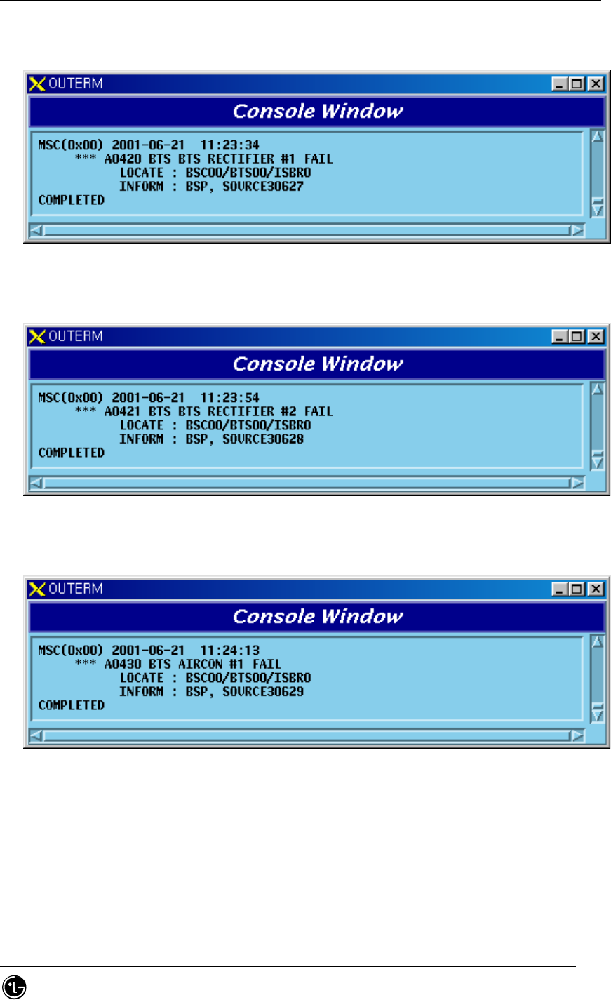
34) When indoor BTS Rectifier #1 fails
Fig. 5.1-272 Indoor BTS ENV Rectifier #1 fails
35) When indoor BTS Rectifier #2 fails
Fig. 5.1-273 Indoor BTS ENV Rectifier #2 Fail
36) When indoor BTS Aircon #1 fails
Fig. 5.1-274 Indoor BTS ENV Aircon #1 Fail
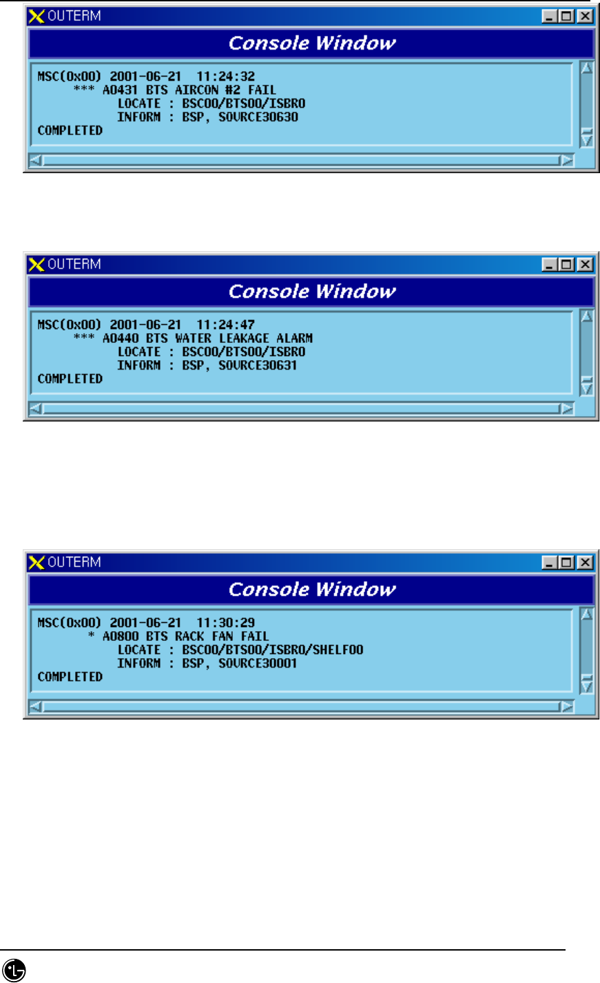
37) When indoor BTS Aircon #2 fails
STAREX-IS BSM Manual
Page:689(877)
Issue:1.
0
SMD-011-PMA210
Fig. 5.1-275 Indoor BTS ENV Aircon #2 Fail
38) Indoor BTS Water Leakage Alarm
Fig. 5.1-276 Indoor BTS ENV Water Leakage Alarm
5.1.1.3.13. Others
1) If a problem occurs in BTS FAN
Fig. 5.1-277 BTS Rack FAN Fail
5.1.2. Fault Message
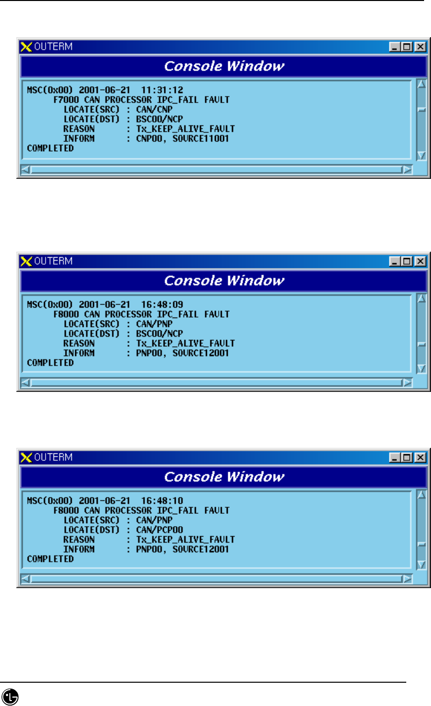
5.1.2.1. Keep-Alive-related Fault
Keep-Alive Fault occurs by two reasons. One in Tx section
STAREX-IS BSM Manual
Page:690(877)
Issue:1.
0
SMD-011-PMA210
5.1.2.1.1.1. CNP Report
1) CNP NCP section
Fig. 5.1-278 Keep-Alive Fault between CNP and NCP
5.1.2.1.1.2. PNP Report
1) PNP NCP section
Fig. 5.1-279 Keep-Alive Fault between PNP and NCP
2) PNP PCP section
Fig. 5.1-280 Keep-Alive Fault between PNP and PCP
5.1.2.1.1.3. PCP Report
1) PCP CCP section
STAREX-IS BSM Manual
Page:691(877)
Issue:1.
0
SMD-011-PMA210
Fig. 5.1-281 Keep-Alive Fault between PCP and CCP
2) PCP PNP section
Fig. 5.1-282 Keep-Alive Fault between PCP and PNP
5.1.2.1.1.4. CCP Report
1) CCP NCP section
Fig. 5.1-283 Keep-Alive Fault between CCP and NCP
2) CCP PCP section
STAREX-IS BSM Manual
Page:692(877)
Issue:1.
0
SMD-011-PMA210
Fig. 5.1-284 Keep-Alive Fault between CCP and PCP
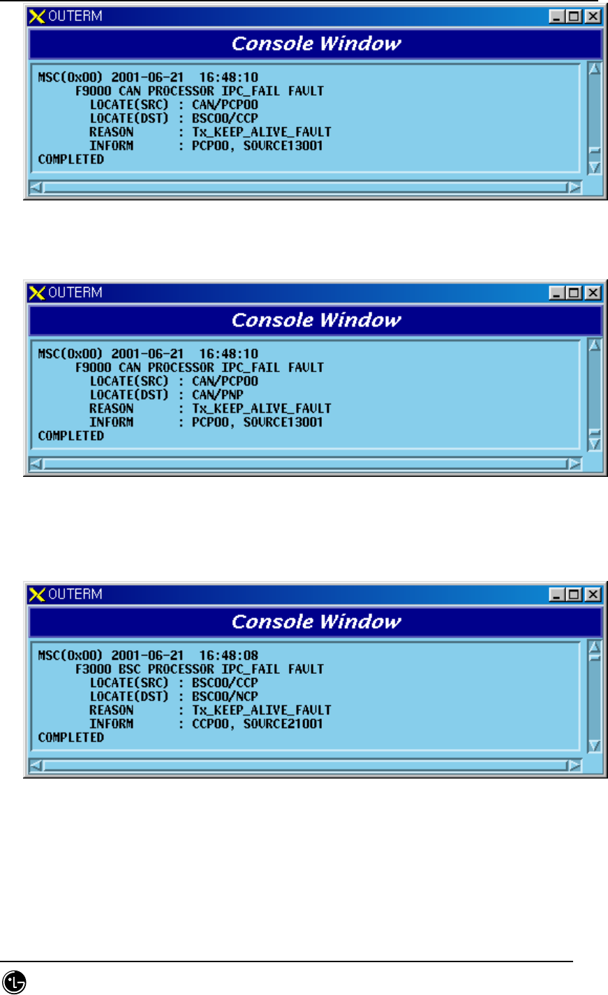
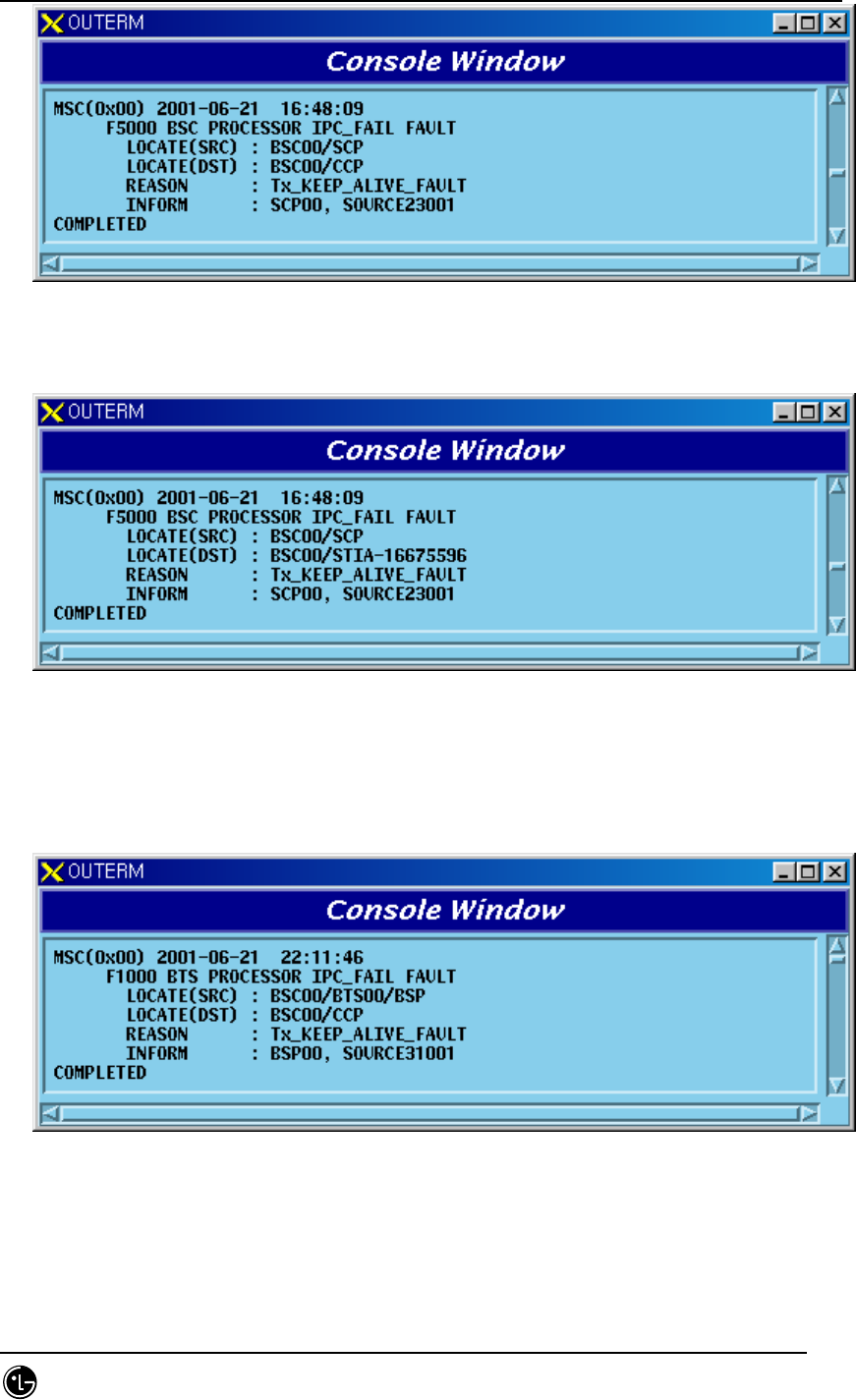
3) CCP BSP section
Fig. 5.1-285 Keep-Alive Fault between CCP and BSP
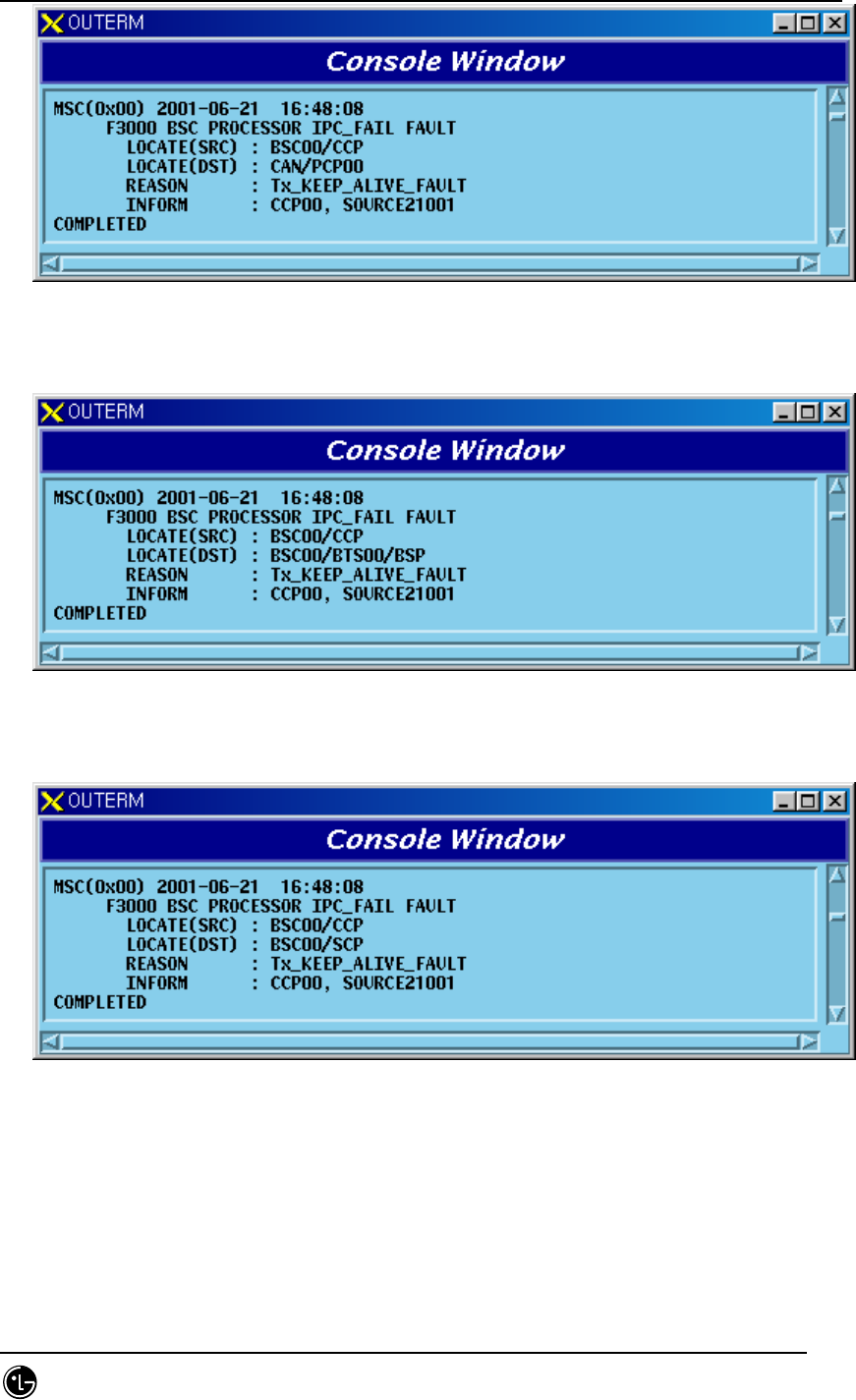
4) CCP SCP section
Fig. 5.1-286 Keep-Alive Fault between CCP and SCP
5) CCP SMP section
STAREX-IS BSM Manual
Page:693(877)
Issue:1.
0
SMD-011-PMA210
Fig. 5.1-287 Keep-Alive Fault between CCP and SMP
6) CCP VMP section
Fig. 5.1-288 Keep-Alive Fault between CCP and VMP
5.1.2.1.1.5. NCP Report
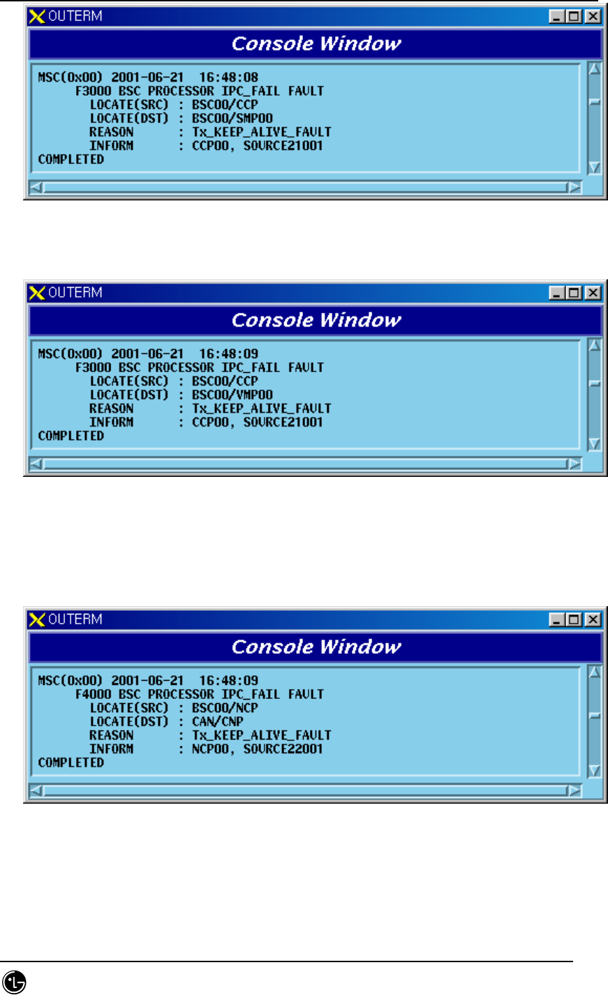
1) NCP CNP section
Fig. 5.1-289 Keep-Alive Fault between NCP and CNP
2) NCP CCP section
STAREX-IS BSM Manual
Page:694(877)
Issue:1.
0
SMD-011-PMA210
Fig. 5.1-290 Keep-Alive Fault between NCP and CCP
3) NCP PNP section
Fig. 5.1-291 Keep-Alive Fault between NCP and PNP
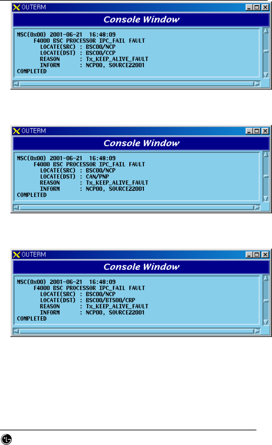
4) NCP CRP section
Fig. 5.1-292 Keep-Alive Fault between NCP and CRP
5.1.2.1.1.6. SCP Report
1) SCP CCP section
STAREX-IS BSM Manual
Page:695(877)
Issue:1.
0
SMD-011-PMA210
Fig. 5.1-293 Keep-Alive Fault between SCP and CCP
2) SCP STIA section
Fig. 5.1-294 Keep-Alive Fault between SCP and STIA
5.1.2.1.1.7. BSP Report
1) BSP CCP section
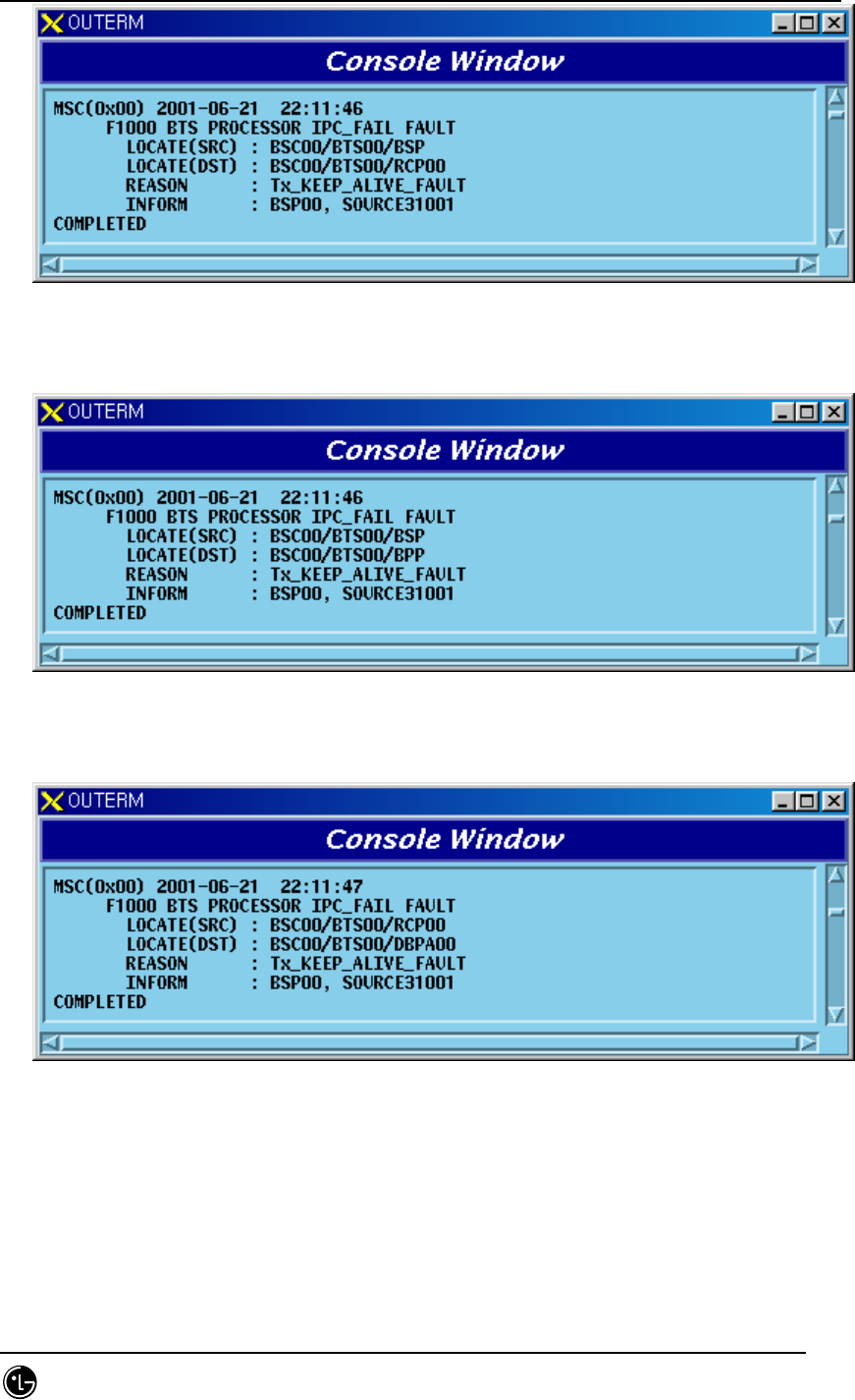
Fig. 5.1-295 Keep-Alive Fault between BSP and CCP
2) BSP RCP section
STAREX-IS BSM Manual
Page:696(877)
Issue:1.
0
SMD-011-PMA210
Fig. 5.1-296 Keep-Alive Fault between BSP and RCP
3) BSP BPP section
Fig. 5.1-297 Keep-Alive Fault between BSP and BPP
4) RCP DBPA section
Fig. 5.1-298 Keep-Alive Fault between RCP and DBPA
5.1.2.2. CCP Processing-related Fault
5.1.2.2.1. VCE Qcelp Algorithm Test Fault
1) Vocoder Clock Fault

STAREX-IS BSM Manual
Page:697(877)
Issue:1.
0
SMD-011-PMA210
Fig. 5.1-299 Vocoder Clock Fault
2) QCELP0 Algorithm Fault
Fig. 5.1-300 QCELP0 Algorithm Fault
3) QCELP1 Algorithm Fault
Fig. 5.1-301 QCELP1 Algorithm Fault
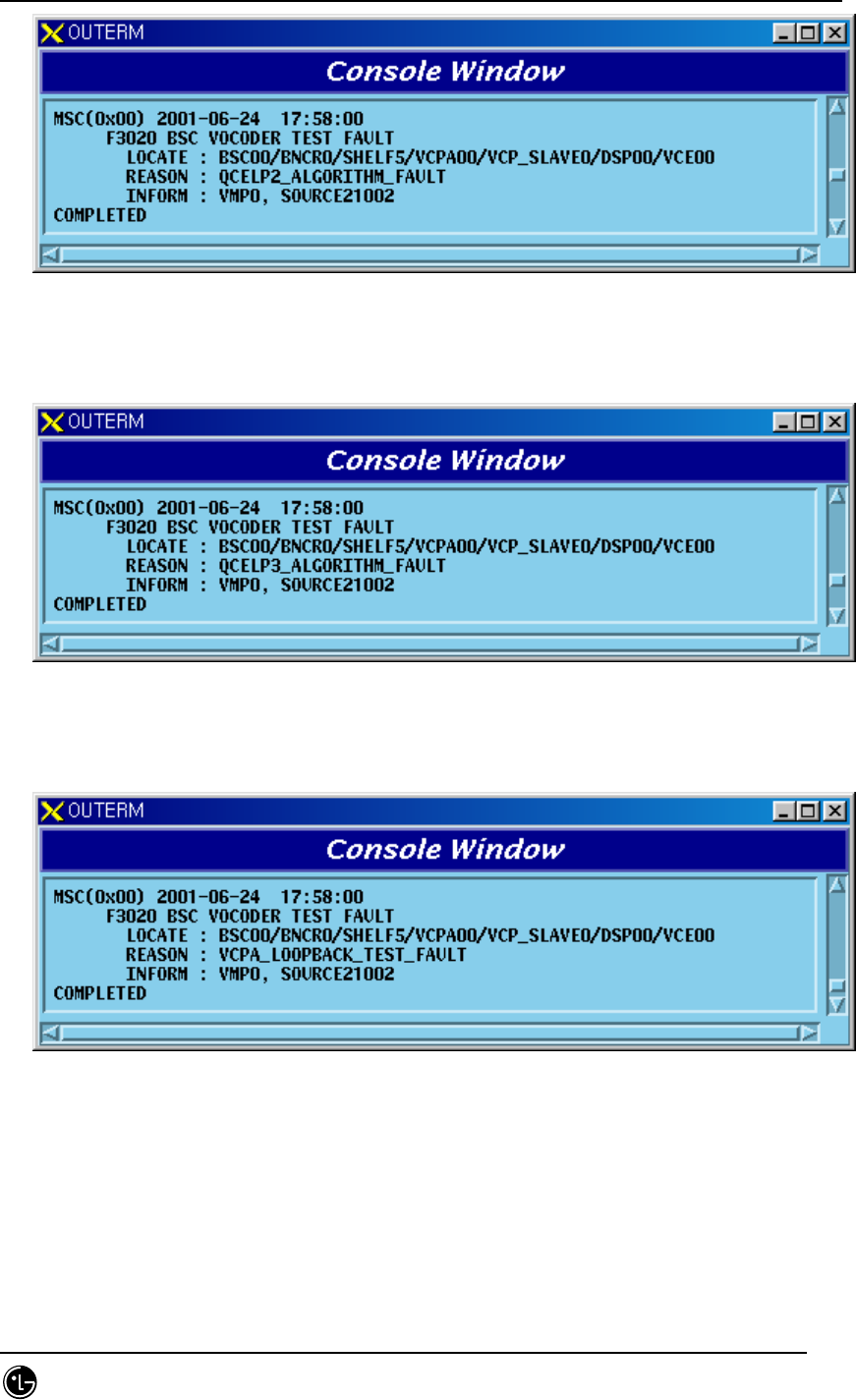
4) QCELP2 Algorithm Fault
STAREX-IS BSM Manual
Page:698(877)
Issue:1.
0
SMD-011-PMA210
Fig. 5.1-302 QCELP2 Algorithm Fault
5) QCELP3 Algorithm Fault
Fig. 5.1-303 QCELP3 Algorithm Fault
6) VCPA LoopBack Test Fault
Fig. 5.1-304 VCPA Loop-Back Test Fault
5.1.2.2.2. VCE DSP Test Fault
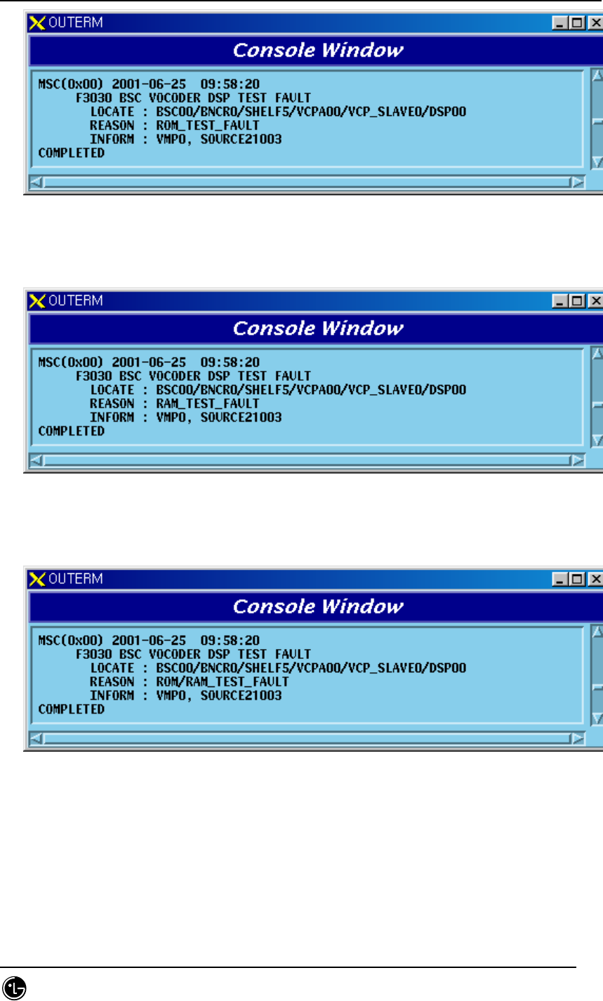
1) When faults occur upon DSP ROM TEST
STAREX-IS BSM Manual
Page:699(877)
Issue:1.
0
SMD-011-PMA210
Fig. 5.1-305 Vocoder DSP ROM TEST Fault
2) When faults occur upon DSP RAM TEST
Fig. 5.1-306 Vocoder DSP RAM TEST Fault
3) When faults occur upon DSP ROM/RAM TEST
Fig. 5.1-307 Vocoder DSP ROM/RAM TEST Fault
4) When faults occur upon DSP ALU TEST

STAREX-IS BSM Manual
Page:700(877)
Issue:1.
0
SMD-011-PMA210
Fig. 5.1-308 Vocoder DSP ALU TEST Fault
5) When faults occur DSP ROM/ALU TEST
Fig. 5.1-309 Vocoder DSP ROM/ALU TEST Fault
6) When faults occur upon DSP RAM/ALU TEST
Fig. 5.1-310 Vocoder DSP RAM/ALU TEST Fault
7) When faults occur upon DSP ROM/RAM/ALU TEST
STAREX-IS BSM Manual
Page:701(877)
Issue:1.
0
SMD-011-PMA210
Fig. 5.1-311 Vocoder DSP ROM/RAM/ALU TEST Fault
5.1.2.2.3. VLIA T1/E1 Trunk Time Slot Fault
1) When faults occur upon VLIA E1/T1 Trunk Time-Slot TEST
Fig. 5.1-312 VLIA E1/T1 Trunk Time-Slot Test Fault
5.1.2.2.4. Call Fail
1) SCI Fault
Fig. 5.1-313 SCI Fault
2) BASE ID Fault

STAREX-IS BSM Manual
Page:702(877)
Issue:1.
0
SMD-011-PMA210
Fig. 5.1-314 Base ID Fault
3) BTS ID Fault
Fig. 5.1-315 BTS ID Fault
4) Sector ID Fault
Fig. 5.1-316 Sector ID Fault
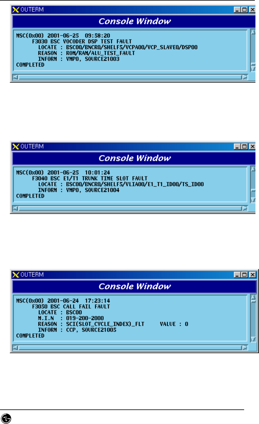
5) Neighbor List Fault
STAREX-IS BSM Manual
Page:703(877)
Issue:1.
0
SMD-011-PMA210
Fig. 5.1-317 Neighbor List Fault
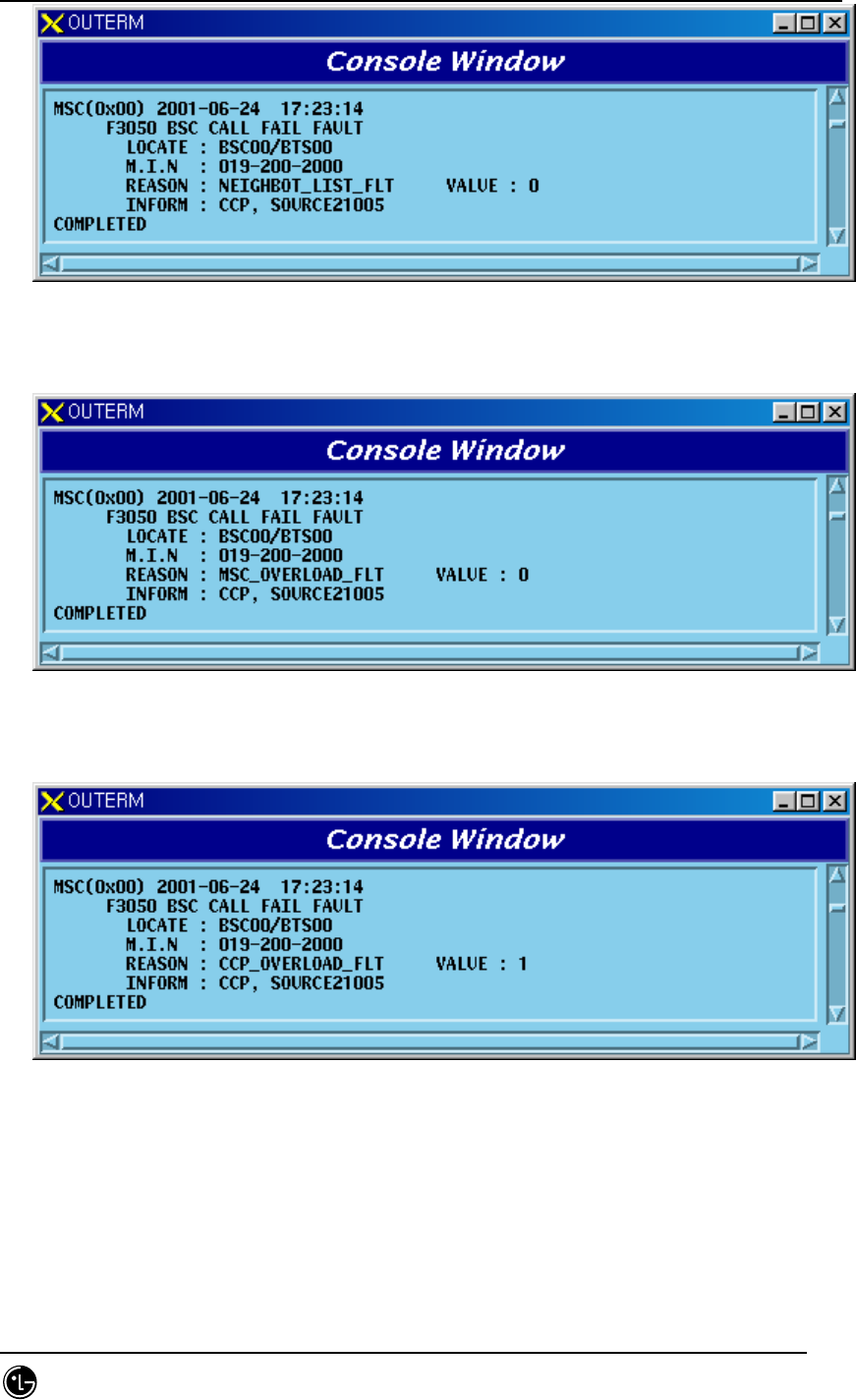
6) MSC Overload Fault
Fig. 5.1-318 MSC Overload Fault
7) CCP Overload Fault
Fig. 5.1-319 CCP Overload Fault
8) BSP Overload Fault
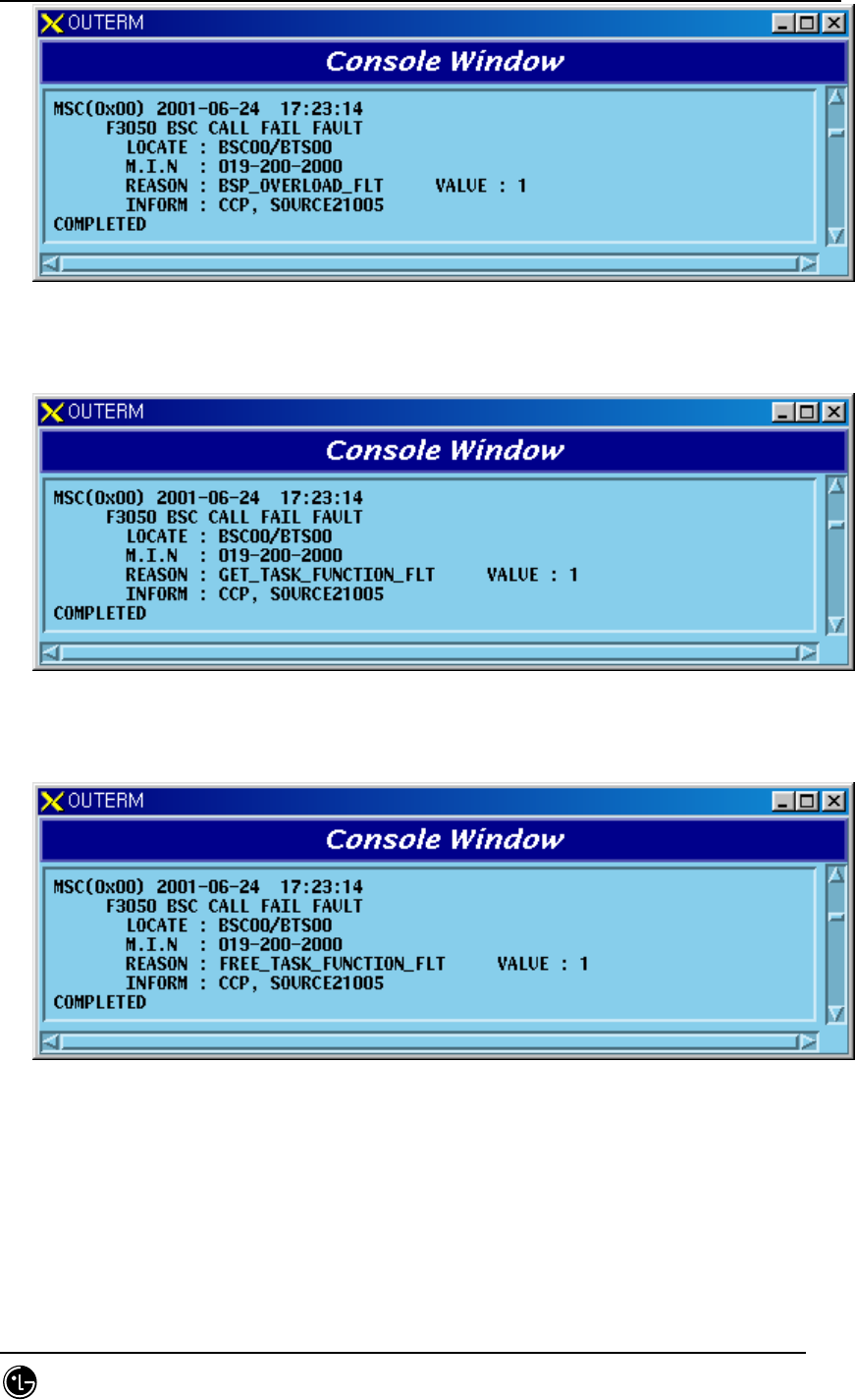
STAREX-IS BSM Manual
Page:704(877)
Issue:1.
0
SMD-011-PMA210
Fig. 5.1-320 BSP Overload Fault
9) Get Task Function Fault
Fig. 5.1-321 Get Task Function Fault
10) Free Task Function Fault
Fig. 5.1-322 Free Task Function Fault
11) Get Buffer Function Fault
STAREX-IS BSM Manual
Page:705(877)
Issue:1.
0
SMD-011-PMA210
Fig. 5.1-323 Get Buffer Function Fault
12) Authentication Fault
Fig. 5.1-324 Authentication Fault
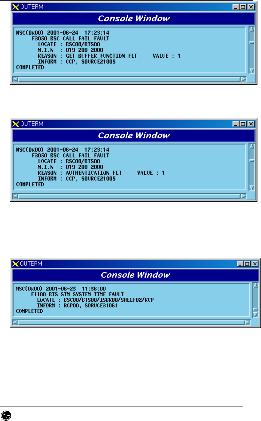
5.1.2.3. RCP Processing-related Fault
1) When a problem occurs in STM SYSTEM TIME
Fig. 5.1-325 STM System Time Fault
2) CDM TX Parity Fault

STAREX-IS BSM Manual
Page:706(877)
Issue:1.
0
SMD-011-PMA210
Fig. 5.1-326 CDM TX Parity Fault
3) CDM RX Parity Fault
Fig. 5.1-327 CDM RX Parity Fault
4) CDM TX Over-Flow Fault
Fig. 5.1-328 CDM TX Over-Flow Fault
5) CDM TX M2R DATA Error

STAREX-IS BSM Manual
Page:707(877)
Issue:1.
0
SMD-011-PMA210
Fig. 5.1-329 CDM TX M2R DATA Error
6) CDM TX R2B DATA Error
Fig. 5.1-330 CDM TX R2B DATA Error
7) CDM RX B2R DATA Error
Fig. 5.1-331 CDM RX B2R DATA Error
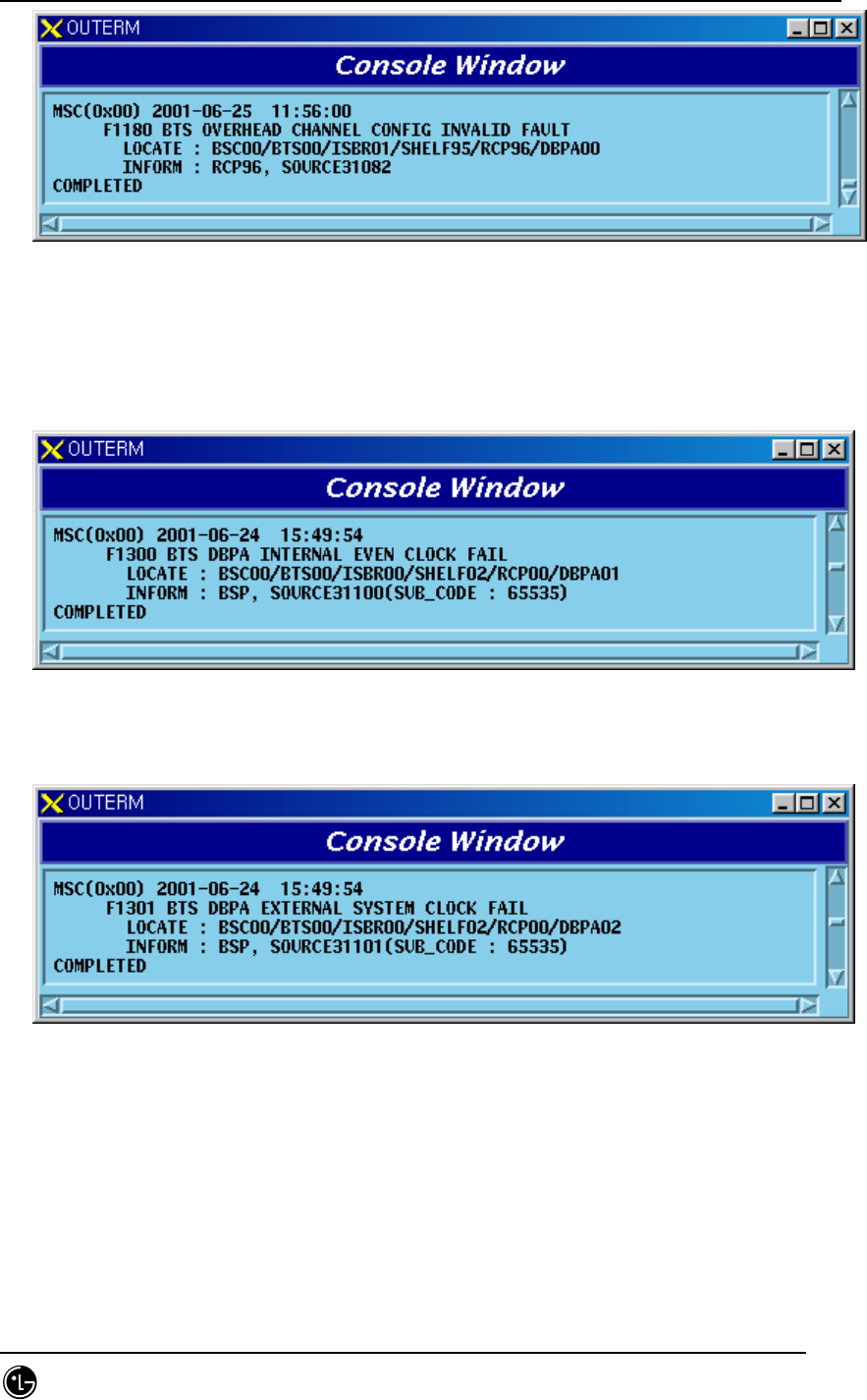
8) OverHead Channel Config No Received Fault
Fig. 5.1-332 OverHead Channel Config No Received Fault
9) OverHead Channel Config Invalid Fault
STAREX-IS BSM Manual
Page:708(877)
Issue:1.
0
SMD-011-PMA210
Fig. 5.1-333 OverHead Channel Config Invalid Fault
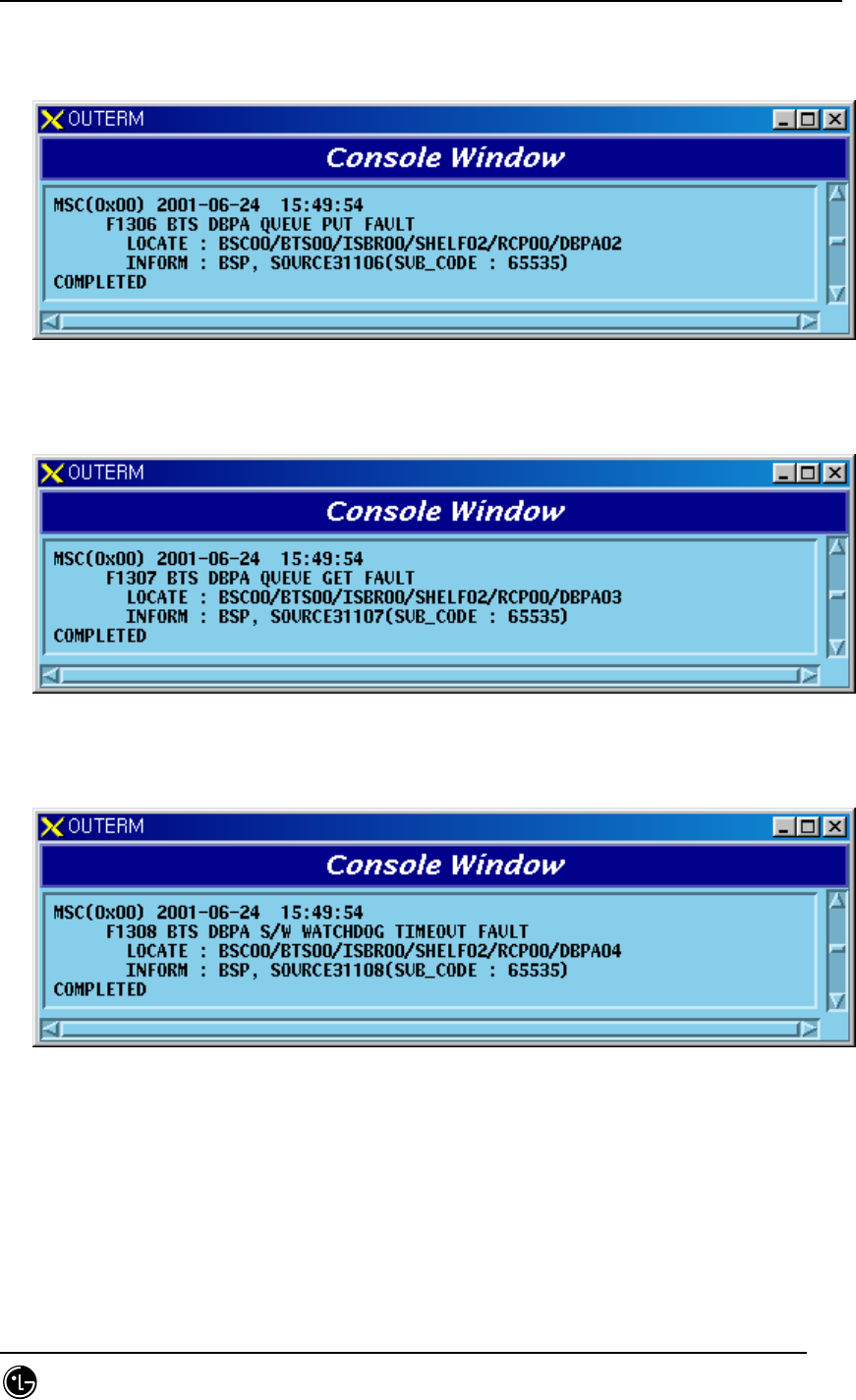
5.1.2.4. DBPA Processing-related Fault
1) When faults occur in DBPA Internal Even Clock
Fig. 5.1-334 DBPA Internal Even Clock Fault
2) When faults occur in DBPA External System Clock
Fig. 5.1-335 DBPA External System Clock Fault
3) When DBPA Channel Card can not receive TOD within 10 seconds

STAREX-IS BSM Manual
Page:709(877)
Issue:1.
0
SMD-011-PMA210
Fig. 5.1-336 DBPA TOD Not Active Fault
4) DBPA Common Channel No Free Queue Fail
Fig. 5.1-337 DBPA CMC No Free Queue Fault
5) When faults occur in DBPA Internal System Clock
Fig. 5.1-338 DBPA Internal Sync Clock Fault
6) DBPA Core No Free Queue Fail
STAREX-IS BSM Manual
Page:710(877)
Issue:1.
0
SMD-011-PMA210
Fig. 5.1-339 DBPA Core No Free Queue Fault
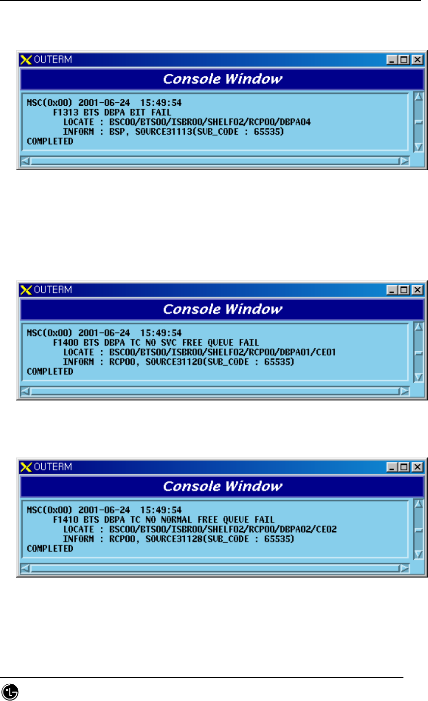
7) DBPA Queue Put Fail
Fig. 5.1-340 DBPA Queue Put Fault
8) DBPA Queue Get Fail
Fig. 5.1-341 DBPA Queue Get Fault
9) DPBA S/W WatchDog TimeOut Fail
Fig. 5.1-342 DBPA S/W Watchdog Timeout Fault
10) DBPA Fatal Fault

STAREX-IS BSM Manual
Page:711(877)
Issue:1.
0
SMD-011-PMA210
Fig. 5.1-343 DBPA Fatal Fault
11) When DBPA Clock and Modem Control are bad
Fig. 5.1-344 DBPA Bad Channel Modem Fault
12) When DBPA has a false TOD information
Fig. 5.1-345 DBPA External TOD Fault
13) DBPA Internal OS Clock Fail
STAREX-IS BSM Manual
Page:712(877)
Issue:1.
0
SMD-011-PMA210
Fig. 5.1-346 DBPA Internal OS Clock Fault
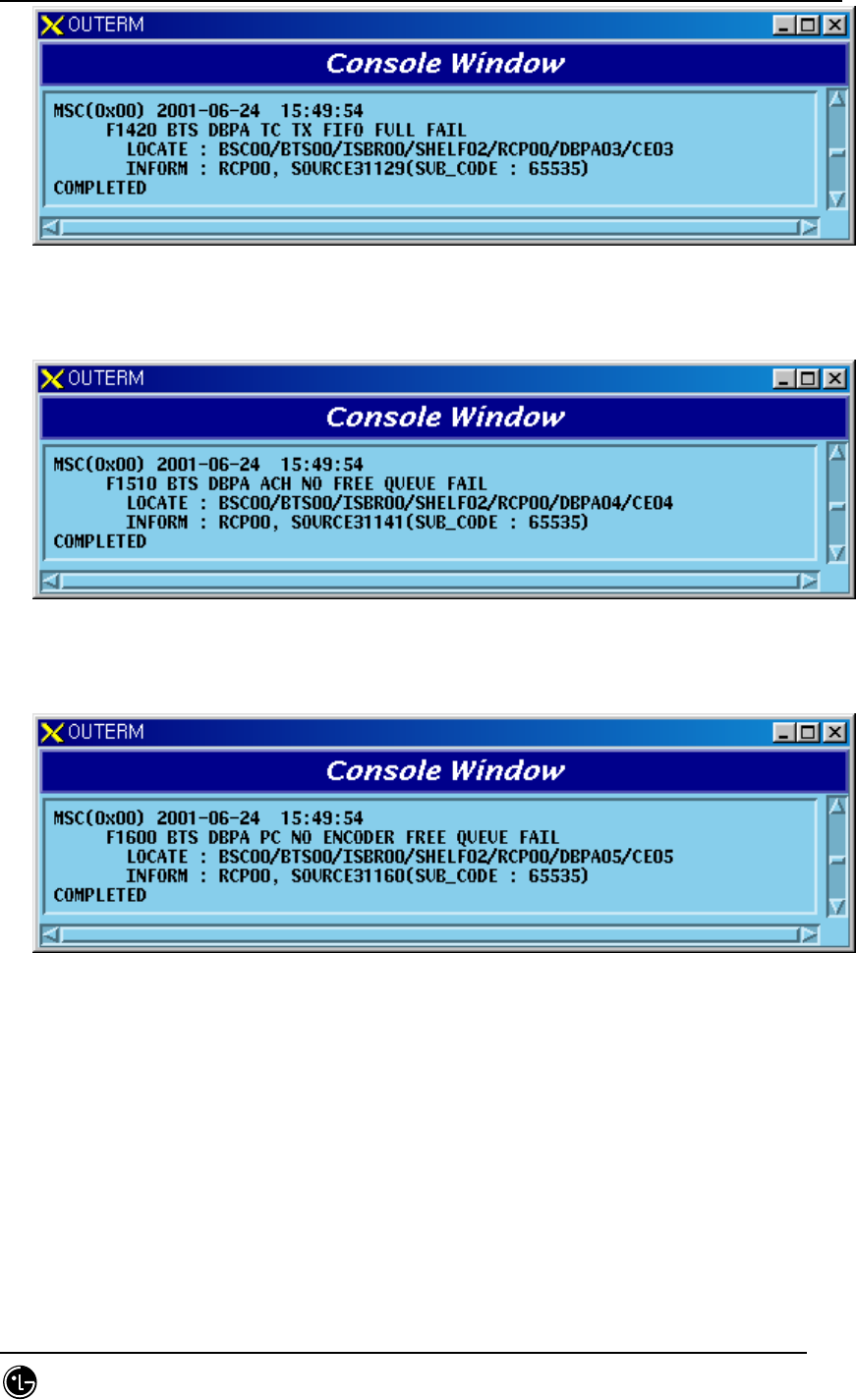
14) DBPA BIT Chip Fail
Fig. 5.1-347 DBPA BIT Fail
5.1.2.5. Channel-related Fault
1) When messages cannot be transferred to SVC because Message Queue for
messages to be delivered to SVC is empty
Fig. 5.1-348 DBPA TC No SVC Free Queue Fail
2) When Queue resources that save messages from BSP and RCP are used up
Fig. 5.1-349 DBPA TC No Normal Free Queue Fail
3) When a problem occurs during Built-In Test
STAREX-IS BSM Manual
Page:713(877)
Issue:1.
0
SMD-011-PMA210
Fig. 5.1-350 DBPA TC Tx FWHENO Full Fail
4) When Queue resources that save messages to be sent to BSP are used up
Fig. 5.1-351 DBPA ACH No Free Queue Fail
5) When Encoder Queue resources are used up
Fig. 5.1-352 DBPA PC No Encoder Free Queue Fail
6) When Queue resources that save page messages except General Page
messages are used up
STAREX-IS BSM Manual
Page:714(877)
Issue:1.
0
SMD-011-PMA210
Fig. 5.1-353 DBPA PC No Page Free Queue Fail
7) When Queue resources that save Quick Page messages are used up
Fig. 5.1-354 DBPA PC No Quick Page Free Queue Fail
8) When Queue resources that save Reply Message are consumed as Reply is
requested for the messages from BSP
Fig. 5.1-355 DBPA PC No Reply Free Queue Fail
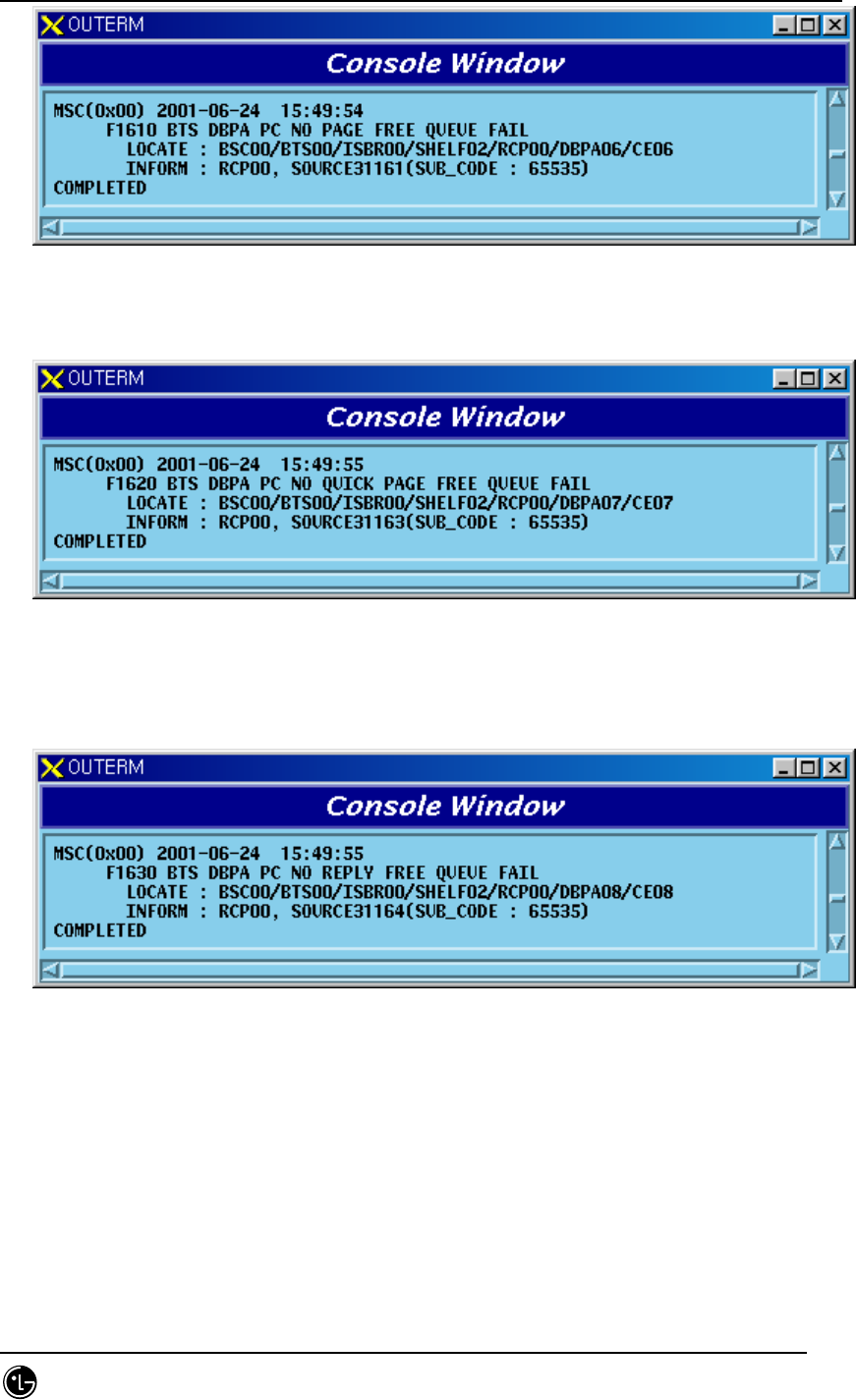
9) When Write errors occur more than 20 times continuously as Paging Channel
performs Write Frame every 20ms
STAREX-IS BSM Manual
Page:715(877)
Issue:1.
0
SMD-011-PMA210
Fig. 5.1-356 DBPA PC Write Frame Fail
10) When Queue resources that save General Page messages from BSP are
consumed
Fig. 5.1-357 DBPA PC No General Page Free Queue Fail
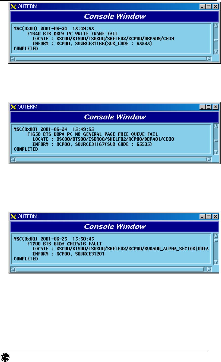
5.1.2.6. BUDA Processing-related Fault
1) BUDA CHIPx16 Fault
Fig. 5.1-358 BUDA CHIPx16 Fault
2) BUDA Forward Sync Fault
STAREX-IS BSM Manual
Page:716(877)
Issue:1.
0
SMD-011-PMA210
Fig. 5.1-359 BUDA Forward Sync Fault
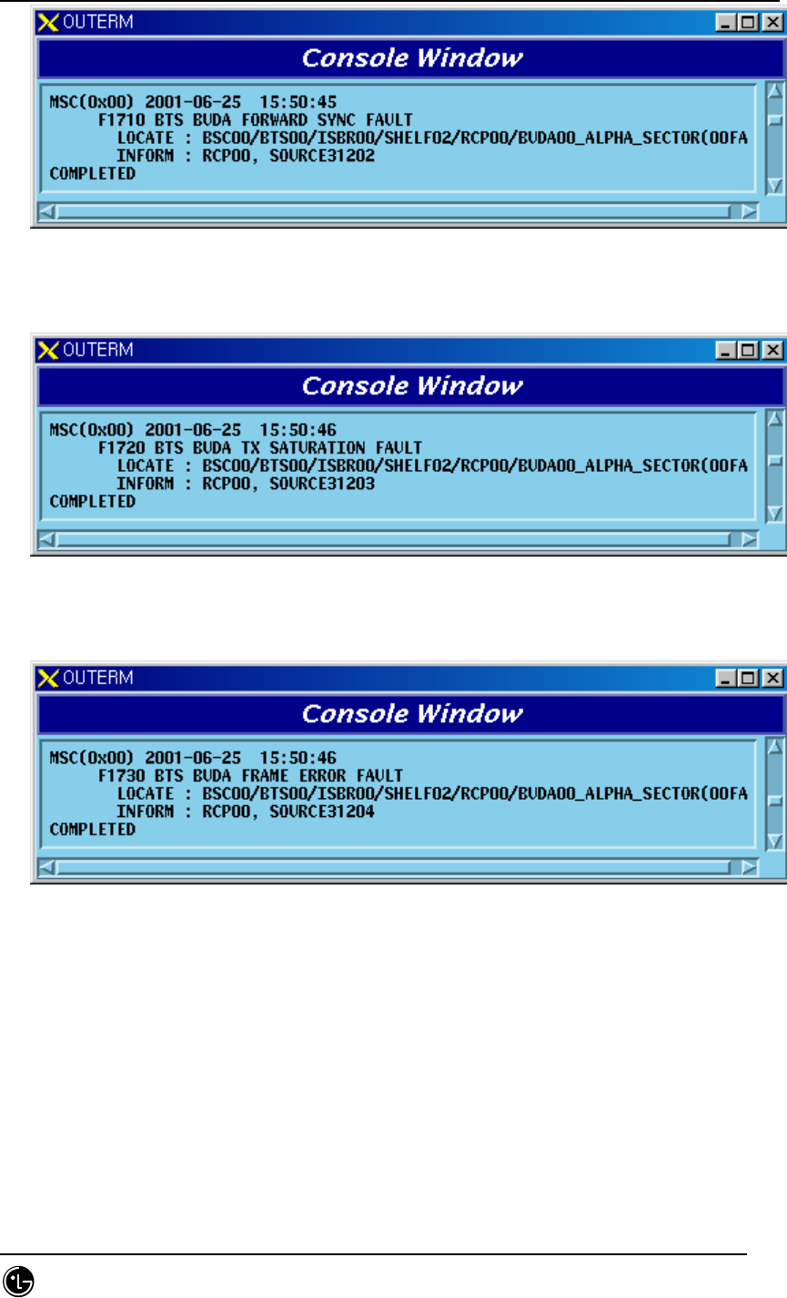
3) BUDA Tx Saturation Fault
Fig. 5.1-360 BUDA Tx Saturation Fault
4) BUDA Frame Error Fault
Fig. 5.1-361 BUDA Frame Error Fault
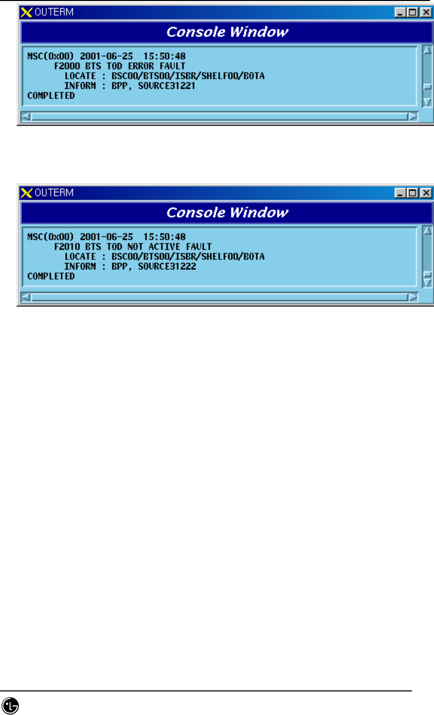
5.1.2.7. BOTA Processing-related Fault
1) BOTA TOD Error Fault
STAREX-IS BSM Manual
Page:717(877)
Issue:1.
0
SMD-011-PMA210
Fig. 5.1-362 BOTA TOD Error Fault
2) BOTA TOD Not Active Fault
Fig. 5.1-363 BOTA TOD Not Active Fault
5.2. Status Command
5.2.1. Processor Status Change Report
When processor status is changed in state block, the status change report messages
are displayed on Console Window. This function can allow or inhibit messages display
as a function that allows/inhibits the status message display..
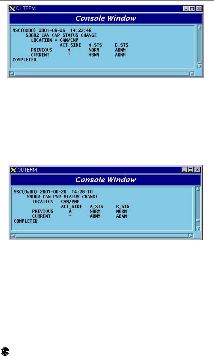
5.2.1.1. CNP Status Change Report
When CNP processor status is changed, the messages are displayed on Console Window.
It is the processor that the BSM keeps Alive and displays the messages, judging from
the BSM status block.
STAREX-IS BSM Manual
Page:718(877)
Issue:1.
0
SMD-011-PMA210
Fig. 5.2-1 CNP Processor Status Change Report
5.2.1.2. PNP Status Change Report
When PNP processor status is changed, the messages are displayed on Console Window.
It is the processor that the BSM keeps Alive and displays the messages, judging from
the BSM status block.
Fig. 5.2-2 PNP Processor Status Change Report
5.2.1.3. PCP Status Change Report
When PCP processor status is changed, the messages are displayed on Console Window.
It is the processor that the BSM keeps Alive and displays the messages, judging from
the BSM status block.
STAREX-IS BSM Manual
Page:719(877)
Issue:1.
0
SMD-011-PMA210
Fig. 5.2-3 PCP Processor Status Change Report
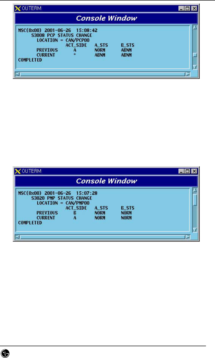
5.2.1.4. PMP Status Change Report
When PMP processor status is changed, the messages are displayed on Console Window.
It is the processor that PCP keeps Alive and reports the messages to the upper level
BSM, judging from the PCP status block.
Fig. 5.2-4 PMP Processor Status Change Report
5.2.1.5. CCP Status Change Report
When CCP processor status is changed, the messages are displayed on Console Window.
It is the processor that the BSM keeps Alive and displays the messages, judging from
the BSM status block.
STAREX-IS BSM Manual
Page:720(877)
Issue:1.
0
SMD-011-PMA210
Fig. 5.2-5 CCP Processor Status Change Report
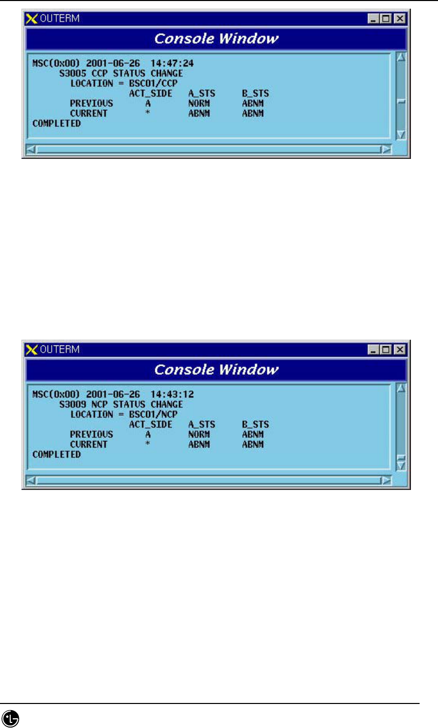
5.2.1.6. NCP Status Change Report
When NCP processor status is changed, the messages are displayed on Console Window.
It is the processor that the BSM keeps Alive and displays the messages, judging from
the BSM status block.
Fig. 5.2-6 NCP Processor Status Change Report
5.2.1.7. SCP Status Change Report
When SCP processor status is changed, the messages are displayed on Console Window.
It is the processor that the BSM keeps Alive and displays the messages, judging from
the BSM status block.
STAREX-IS BSM Manual
Page:721(877)
Issue:1.
0
SMD-011-PMA210
Fig. 5.2-7 SCP Processor Status Change Report
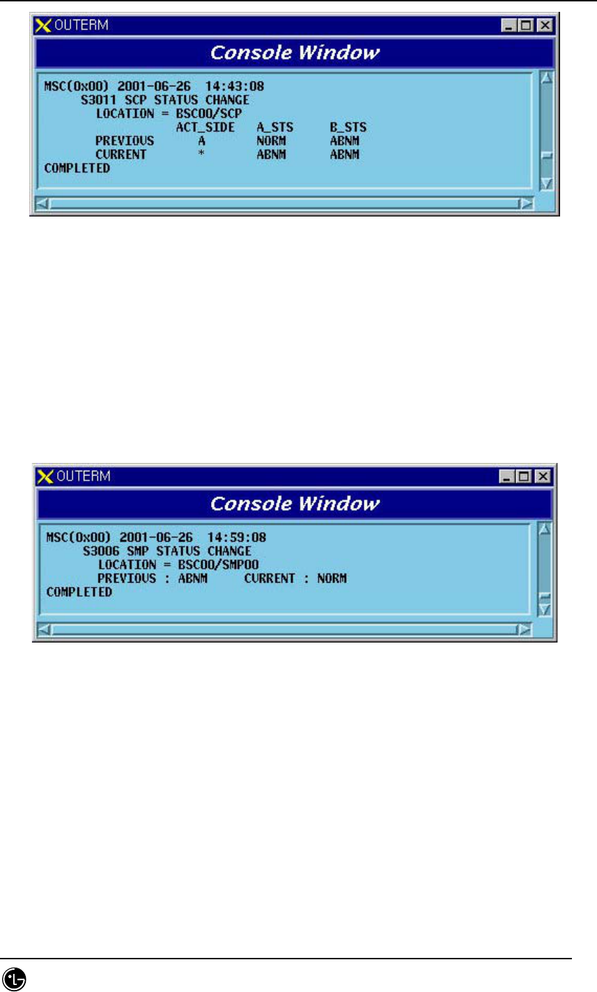
5.2.1.8. SMP Status Change Report
When SMP processor status is changed, the messages are displayed on Console Window.
It is the processor that the CCP keeps Alive and reports the messages to the upper
level BSM, judging from the CCP status block.
Fig. 5.2-8 SMP Processor Status Change Report
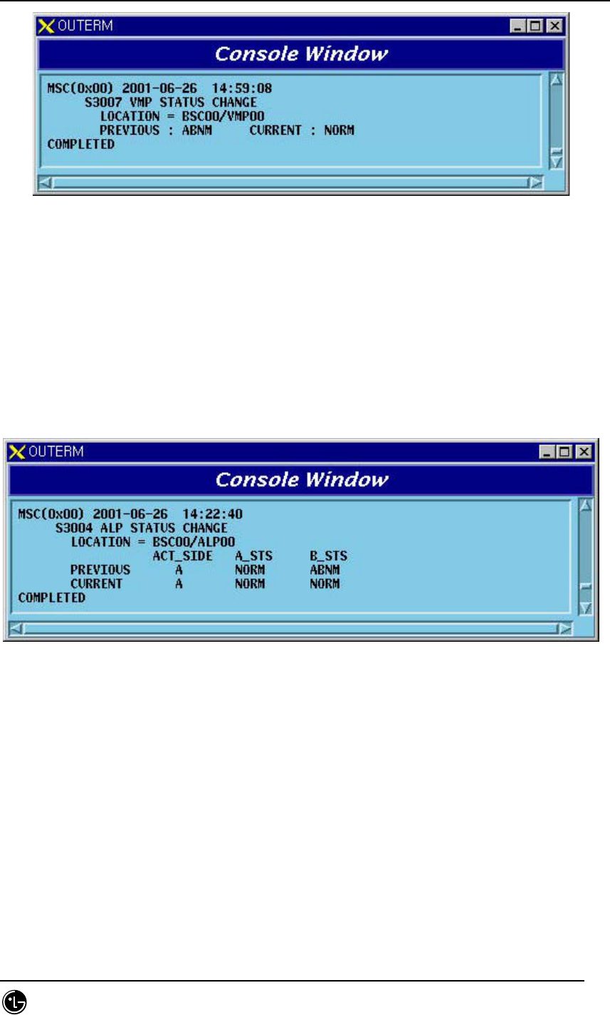
5.2.1.9. VMP Status Change Report
When VMP processor status is changed, the messages are displayed on Console Window.
It is the processor that the CCP keeps Alive and reports the messages to the upper
level BSM, judging from the CCP status block.
STAREX-IS BSM Manual
Page:722(877)
Issue:1.
0
SMD-011-PMA210
Fig. 5.2-9 VMP Processor Status Change Report
5.2.1.10. ALP Status Change Report
When ALP processor status is changed, the messages are displayed on Console Window.
It is the processor that the CCP keeps Alive and reports the messages to the upper
level BSM, judging from the CCP status block.
Fig. 5.2-10 ALP Processor Status Change Report
5.2.1.11. BSP Status Change Report
When BSP processor status is changed, the messages are displayed on Console Window.
It is the processor that the CCP keeps Alive and reports the messages to the upper
level BSM, judging from the CCP status block.
STAREX-IS BSM Manual
Page:723(877)
Issue:1.
0
SMD-011-PMA210
Fig. 5.2-11 BSP Processor Status Change Report
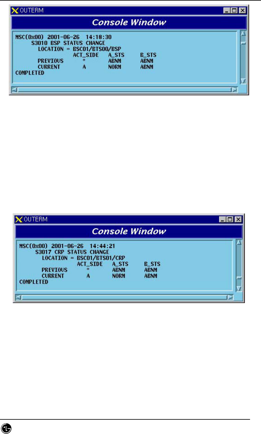
5.2.1.12. CRP Status Change Report
When CRP processor status is changed, the messages are displayed on Console Window.
It is the processor that the NCP keeps Alive and reports the messages to the upper
level BSM, judging from the NCP status block.
Fig. 5.2-12 CRP Processor Status Change Report
5.2.1.13. RCP Status Change Report
When RCP processor status is changed, the messages are displayed on Console Window.
It is the processor that the BSP keeps Alive and reports the messages to the upper
level BSM, judging from the BSP status block.
STAREX-IS BSM Manual
Page:724(877)
Issue:1.
0
SMD-011-PMA210
Fig. 5.2-13 RCP Processor Status Change Report
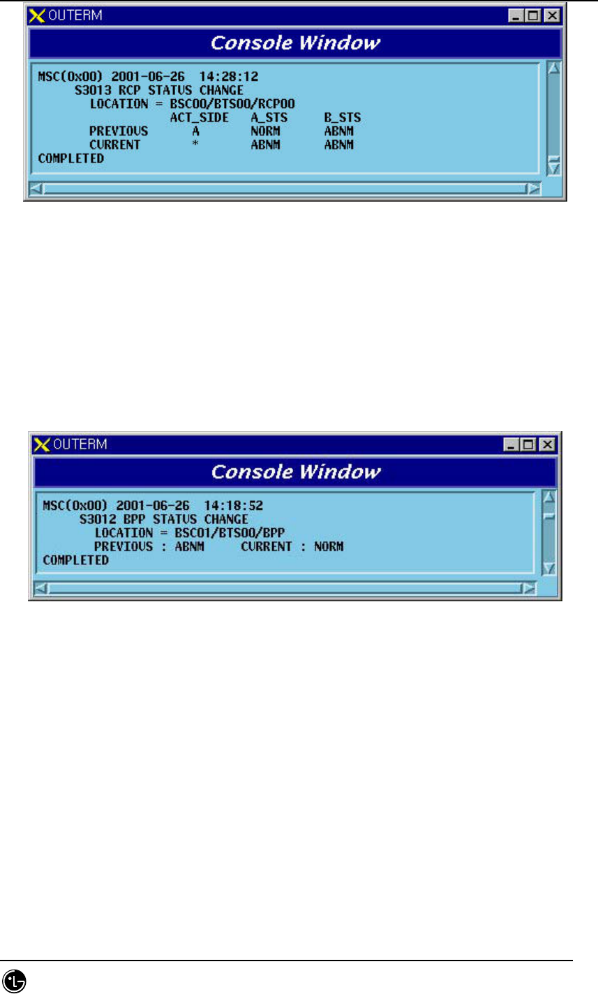
5.2.1.14. BPP Status Change Report
When BPP processor status is changed, the messages are displayed on Console Window.
It is the processor that the BSP keeps Alive and reports the messages to the upper
level BSM, judging from the BSP status block.
Fig. 5.2-14 BPP Processor Status Change Report
5.2.2. Overload Status Change Report Function
When overload occurs/is changed/is released in CCP or BSP processor, it is displayed
on Console Window. This function can allow or inhibit message display as a function
that allows/inhibits the status message display.
STAREX-IS BSM Manual
Page:725(877)
Issue:1.
0
SMD-011-PMA210
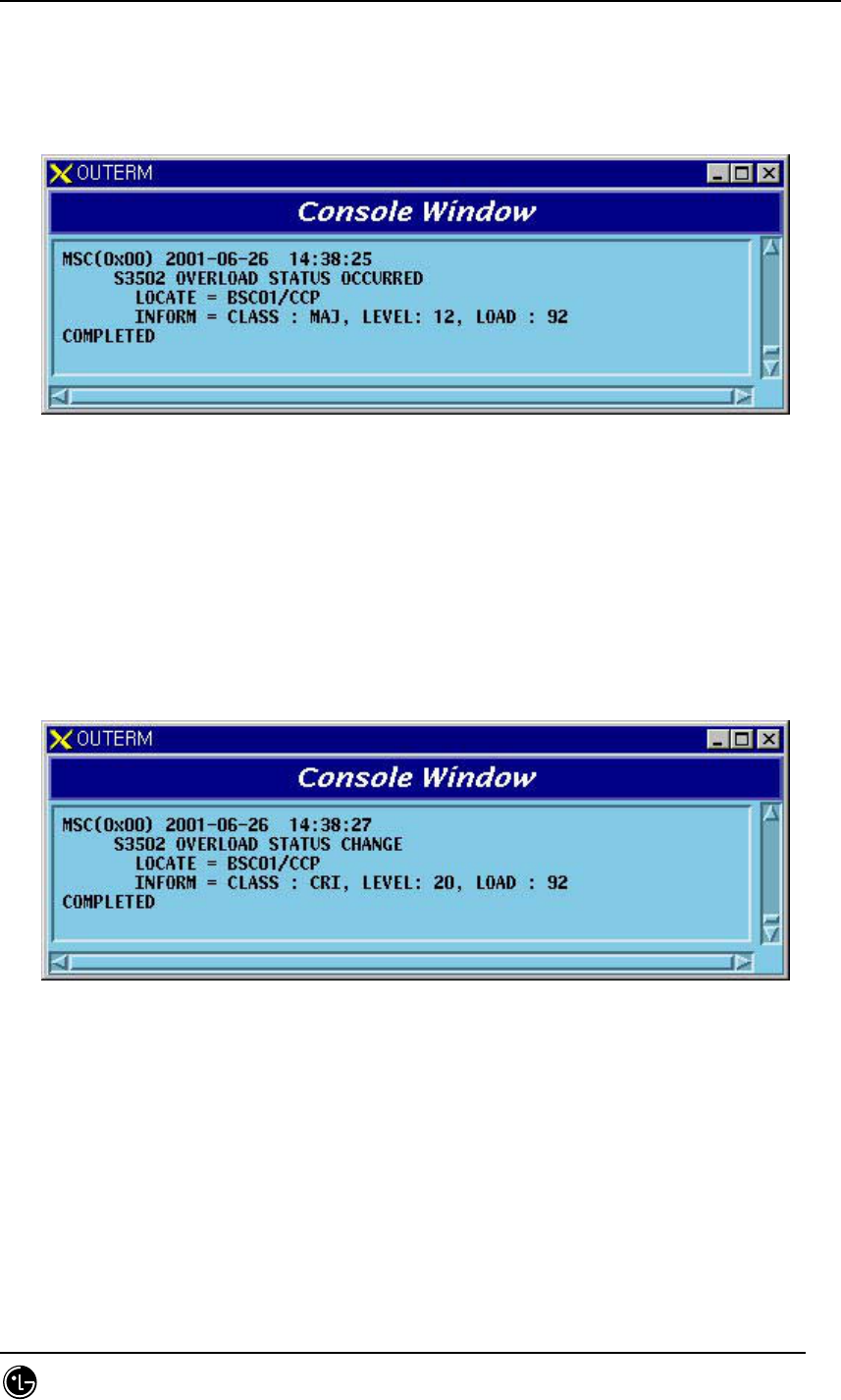
5.2.2.1. Overload Status Occurred Message
When overload occurs in CCP or BSP processor, it is reported to upper level BSM.
Overload occurs when Level is 12.
Fig. 5.2-15 Overload Status Occurred Message
5.2.2.2. Overload Status Change Message
After overload occurs in CCP or BSP processor, when overload status is changed, it is
reported to upper level BSM.
Fig. 5.2-16 Overload Status Change Message
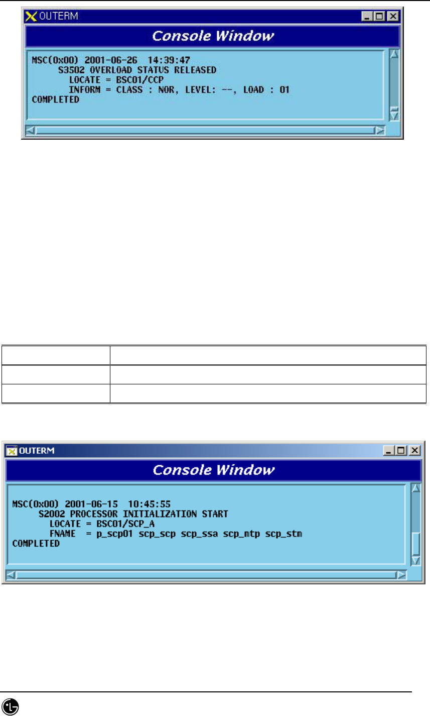
5.2.2.3. Overload Status Released Message
When overload is released in CCP or BSP processor, it is reported to upper level BSM.
STAREX-IS BSM Manual
Page:726(877)
Issue:1.
0
SMD-011-PMA210
Fig. 5.2-17 Overload Status Released Message
5.3. Loading Message
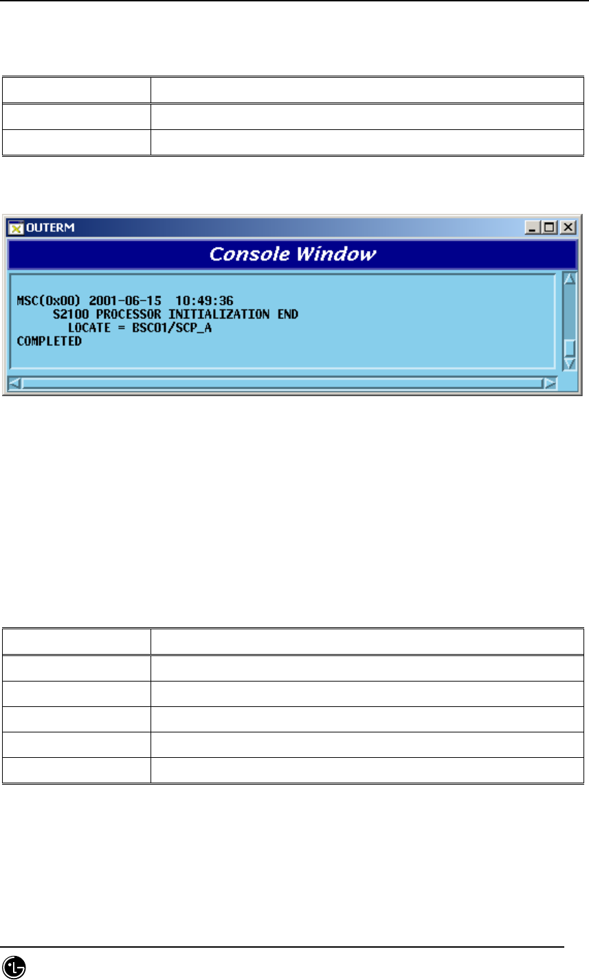
5.3.1. Processor Initialization Start Message
Processor initialization start message is displayed when a target processor starts
initialization. The following messages are displayed depending on the initialization type.
Classification Message Type
Initial Loading S2002 PROCESSOR INITIALIZATION START
Standby Loading S2002 PROCESSOR STANDBY INITIALIZATION START
Fig. 5.3-1 Processor Initialization Start Message
5.3.2. Processor Initialization End Message
STAREX-IS BSM Manual
Page:727(877)
Issue:1.
0
SMD-011-PMA210
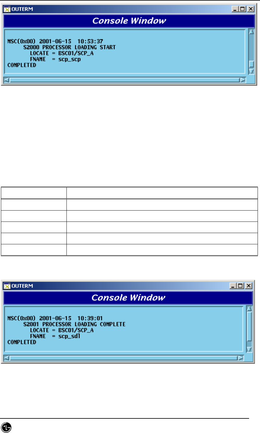
Processor initialization end message is displayed when a target processor ends
initialization. The following messages are displayed depending on the initialization type.
Classification Message Type
Initial Loading S2100 PROCESSOR INITIALIZATION END
Standby Loading S2100 PROCESSOR STANDBY INITIALIZATION END
Fig. 5.3-2 Processor Initialization End Message
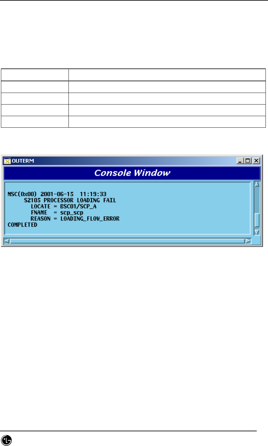
5.3.3. Loading Start Message
Processor loading start message is a message that reports loading start of each block
upon loading target processor. The following messages are displayed depending on the
loading type.
Classification Message Type
General Loading S2000 PROCESSOR LOADING START
Block Loading S2000 PROCESSOR BLOCK LOADING START
Activation Loading S2000 PROCESSOR ACTIVATION LOADING START
Standby Loading S2000 PROCESSOR STANDBY LOADING START
Firmware Loading S2000 PROCESSOR FIRMWARE LOADING START
STAREX-IS BSM Manual
Page:728(877)
Issue:1.
0
SMD-011-PMA210
Fig. 5.3-3 Loading Start Message
5.3.4. Loading Completion Message
Processor loading completion message is a message that reports loading completion of
each block upon loading target processor. The following messages are displayed
depending on the loading type.
Classification Message Type
General Loading S2001 PROCESSOR LOADING COMPLETE
Block Loading S2001 PROCESSOR BLOCK LOADING COMPLETE
Activation Loading S2001 PROCESSOR ACTIVATION LOADING COMPLETE
Standby Loading S2001 PROCESSOR STANDBY LOADING COMPLETE
Firmware Loading S2001 PROCESSOR FIRMWARE LOADING COMPLETE
Fig. 5.3-4 Loading Completion Message
STAREX-IS BSM Manual
Page:729(877)
Issue:1.
0
SMD-011-PMA210
5.3.5. Loading Failure Message
Processor loading failure message is a message displayed when block fails in loading
upon loading target processor. The following messages are displayed depending on the
loading type.
Classification Message Type
General Loading S2105 PROCESSOR LOADING FAIL
Block Loading S2105 PROCESSOR BLOCK LOADING FAIL
Activation Loading S2105 PROCESSOR ACTIVATION LOADING FAIL
Standby Loading S2105 PROCESSOR STANDBY LOADING FAIL
Fig. 5.3-5 Loading Failure Message
5.3.6. Firmware Update Report Message
Firmware update report message is a message that reports if the update succeeds
when firmware update is completed.

STAREX-IS BSM Manual
Page:730(877)
Issue:1.
0
SMD-011-PMA210
6. Trouble Shoot
This chapter describes problems caused by operating and solution to them.
6.1. If BSM is not operated
6.1.1. If BSM is not initialized
6.1.1.1. Shared Memory or Queue Problem
6.1.1.1.1. IPC Initialization Problem
If the following messages are displayed
start of MMI_server program
[mmi] mmi is already in service.
You can remove a file "IPCHEAD" and try again... sorry!!!
The above cases can occur when BSM is already initialized and used or when
the formerly executed BSM ends abnormally or by force. When these cases
occur, it is possible to delete them compulsorily using
rmipc
command provided
by BSM. However, when initializing IPC by force, perform the work after
checking if it is currently in operation. (See “ Overlapped Use Problem of IPC” if
UNIX ID which operated BSM previously is different from the ID currently
logged in.
6.1.1.1.2. Overlapped Use Problem of IPC
BSM initialization and operation can be performed by logging in as one UNIX
ID. But after executing BSM by logging in as other UNIX IDs, none can
reoperate BSM except the operated ID. Therefore, check Queue and Shared
Memory currently in use by using UNIX command called “
/usr/bin/ipcs
–
a
”
to
see if other IDs operated BSM. In this case, remove the generated IPC Header
and the assigned IPC by performing
“
rmipc
”
command with ID or UNIX Root
authorization that operates BSM

STAREX-IS BSM Manual
Page:731(877)
Issue:1.
0
SMD-011-PMA210
6.1.1.1.3. If IPC is not deleted
If IPC is not deleted by “
rmipc
” command to operate BSM, delete it by force
through the following command.
ipcrm [ -m shmid ] [ -q msqid ] [ -s semid ] [ -M shmkey ]
[ -Q msgkey ] [ -S semkey ]
Description of each factor
-m shmid Remove the shared memory identWhenier shmid from
the
system. The shared memory segment and data struc-
ture associated with it are destroyed after the
last detach.
-q msqid Remove the message queue identWhenier msqid from the
system and destroy the message queue and data
structure associated with it.
-s semid Remove the semaphore identWhenier semid from
the
system and destroy the set of semaphores and data
structure associated with it.
-M shmkey Removes the shared memory identWhenier, created
with
key shmkey, from the system. The shared memory
segment and data structure associated with it are
destroyed after the last detach.
-Q msgkey Remove the message queue identWhenier, created
with
key msgkey, from the system and destroy the mes-
sage queue and data structure associated with it.
-S semkey Remove the semaphore identWhenier, created with key
semkey, from the system and destroy the set of

STAREX-IS BSM Manual
Page:732(877)
Issue:1.
0
SMD-011-PMA210
semaphores and data structure associated with it.
6.1.2. It can not function normally despite of its initialization
6.1.2.1. Informix Problem
BSM Applications are saved as temporary data and data for reference in other
blocks using Informix Database. Therefore, if Informix does not operate, BMS
Applications cannot be run or run abnormally.
6.1.2.1.1. Informix Initialization
Check to see if Informix Database is normally operated by using the following
command:
“
onstat
–“
Normal if messages similar to the following are displayed.
Informix Dynamic Server Version 7.31.UD1 -- On-Line -- Up 1 days 22:53:08 -- 133904 Kbytes
If error messages are displayed, refer to the item “ Informix Installation” of BSM
environmental configuration.
6.1.2.1.2. Informix Database Error
Informix DB errors occur in the following cases: 1) when Database is damaged while
operating the BSM; 2) when Applications are not normally run after normal
initialization of Informix and 3) when a part of all Applications cannot be run. In this
case, it is able to run Applications normally by dropping DB Table of Informix
Database artificially.
6.2. If Graphic Application is not run
BSM inputs a command in the user-friendly environment and provides a variety of
GUIs to monitor the system. However, the user should check the environment to
run GUI.
The following describes causes for errors and its solution when environment
variables are wrongly set up or the files needed for operating GUI do not exist.

STAREX-IS BSM Manual
Page:733(877)
Issue:1.
0
SMD-011-PMA210
6.2.1. Environment Variables
6.2.1.1. Display Setup Problem
Register the system that corresponds to /etc/host files to protect BSM from external
Access and allow to use the authenticated system.
Make the format consistent with the following contents:
6.2.1.1.1. Main Server Name
150.150.62.100 zen.lgic.co.kr zen loghost
In the above example, it is /etc/hosts file to operate the host called “zen” as a
main server.
If the following is registered, the BSM causes segmentation fault and stops
operation.
150.150.62.100 zen zen.lgic.co.kr loghost
6.2.1.1.2. Remote Server
Even if PC/Workstation to be operated in remote area is the same as the above
item, register the following contents in /etc/hosts file.
150.150.62.102 feel.lgic.co.kr feel
The above example is the contents that register the system called “feel” to
access the Main Server. Register the following contents in a /etc/hosts file of
the
Main Server.
6.2.1.2. GUI Library
When GUI is operated, the following messages are displayed on xterm window
that runs mmi. If GUI is not operated, it can be regarded as GUI without library.
ld.so.1: stmGUI: fatal: libXpm.so.4.10: open failed: No such file or directory
Killed

STAREX-IS BSM Manual
Page:734(877)
Issue:1.
0
SMD-011-PMA210
The above is an example when GUI is not operated in spite of the attempt to
operate GUI called “stmGUI”. It means that libXpm.so.x.xx file does not exist as
shown above. In this case, two problems can be taken into consideration.
6.2.1.2.1. LD_LIBRARY_PATH Setup
Setting up GUI Library is to change the system environment variables called
LD_LIBRARY_PATH
.
The following is an example of how to set up variables.
setenv LD_LIBRARY_PATH “
paths
”
The above path would be composed of the following contents:
/home/informix/lib:/home/informix/lib/esql:/opt/TclPro1.5/solaris-
sparc/lib:/usr/openwin/lib:/usr/lib:/usr/ucblib:/usr/dt/lib:../DATA/LIB
GUI Libraries are generally installed in “/usr/dt/lib” or “/usr/openwin/lib”.
However, add “:
your_lib_path_dir
” upon using them additionally.
6.2.1.2.2. libXpm File Absence
Even though OS is normally installed, XPM Library is not provided as a basic.
Therefore, it is possible to set up by duplicating XPM Library provided by BSM
and by adding Library to variables. Refer to the above item
“LD_LIBRARY_PATH” for setting up.
6.2.2. If Manager in Remote Area is not operated
For safety, BSM does not allow to use two managers in one system remotely.
Therefore, check to see if it corresponds to the following cases:
6.2.2.1. If the same name is already used
Check to see if the system attempting a remote operation uses the name already.
It is possible to check if it is registered by operating controller on Main BSM
Server. In this case, if the current system does not use the name, it means that it
was abnormally terminated during the previous use. Therefore, it will be
possible to reuse it if Main BSM controller deletes the corresponding host name.

STAREX-IS BSM Manual
Page:735(877)
Issue:1.
0
SMD-011-PMA210
6.2.2.2. If it is not registered in /etc/hosts file
It is when registration is not allowed for security reasons. In this case, refer to
how to compile /etc/hosts file of BSM environment variables setting among the
above items and then add remote server name.

STAREX-IS BSM Manual
Page:736(877)
Issue:1.
0
SMD-011-PMA210
7. CHG- Appendix
7.1. Alarm/Fault Message Description and List
7.1.1. Alarm Message Description and List
7.1.1.1. CAN Generated Alarm Message
Table 7.1-1 CAN Generated Alarm Message List
Alarm
Code Alarm Description
A7500 CAN GPSR CONTROL CABLE OPEN
A7600 CAN ALARM CABLE OPEN
A7800 CAN RACK FAN FAIL
A8000 CAN GPSR SINGLE ABNORMAL
A8001 CAN GPSR DUAL ABNORMAL
A8050 CAN GPSD SINGLE ABNORMAL
A8051 CAN GPSD DUAL ABNORMAL
A8100 CAN RAPU ABNORMAL
A8110 CAN RAPU LINK_OR_POWER FAIL
A8500 CAN CNPA SINGLE ABNORMAL
A8501 CAN CNPA DUAL ABNORMAL
A8550 CAN ASCA(CAMU) SINGLE ABNORMAL
A8551 CAN ASCA(CAMU) DUAL ABNORMAL
A8560 CAN FERA SINGLE ABNORMAL
A8561 CAN FERA DUAL ABNORMAL
A8570 CAN ASCA(CPNU) SINGLE ABNORMAL
A8571 CAN ASCA(CPNU) DUAL ABNORMAL
A8600 CAN PNPA SINGLE ABNORMAL
A8601 CAN PNPA DUAL ABNORMAL
A8700 CAN AMPA ABNORMAL
A8710 CAN PCPA SINGLE ABNORMAL
A8711 CAN PCPA DUAL ABNORMAL
A8720 CAN PMPA SINGLE ABNORMAL

STAREX-IS BSM Manual
Page:737(877)
Issue:1.
0
SMD-011-PMA210
A8721 CAN PMPA DUAL ABNORMAL
A8730 CAN ENPA SINGLE ABNORMAL
A8731 CAN ENPA DUAL ABNORMAL
A8740 CAN BCRA SINGLE ABNORMAL
A8741 CAN BCRA DUAL ABNORMAL
A8800 CAN PCPA 1PPS CLOCK FAIL
A8810 CAN PCPA 10MHz CLOCK FAIL
A8820 CAN FERA LINK FAIL
A8840 CAN FERA PDSN LINK FAIL
A9000 CAN CAMU SINGLE POWER FAIL
A9001 CAN CAMU DUAL POWER FAIL
A9010 CAN PCFU(PCP) SINGLE POWER FAIL
A9011 CAN PCFU(PCP) DUAL POWER FAIL
A9020 CAN PCFU(PMP) SINGLE POWER FAIL
A9021 CAN PCFU(PMP) DUAL POWER FAIL
A9030 CAN ATSU SINGLE POWER FAIL
A9031 CAN ATSU DUAL POWER FAIL
A9040 CAN CPNU SINGLE POWER FAIL
A9041 CAN CPNU DUAL POWER FAIL
A9220 CAN ASIA(CAMU) SINGLE ABNORMAL
A9221 CAN ASIA(CAMU) DUAL ABNORMAL
A9230 CAN ASIA(CPNU) SINGLE ABNORMAL
A9231 CAN ASIA(CPNU) DUAL ABNORMAL
A9240 CAN AOTA BOARD DELETION
A9250 CAN AOTA FUNCTION FAIL
A9260 CAN ATSA(ASMU) BOARD DELETION
A9270 CAN ATSA(ASMU) FUNCTION FAIL
A9300 CAN PIPA BOARD DELETION
A9310 CAN PIPA FUNCTION FAIL
A9320 CAN FETA BOARD DELETION
A9330 CAN FETA FUNCTION FAIL
A9400 CAN ATSA(ATSU) BOARD DELETION
A9410 CAN ATSA(ATSU) FUNCTION FAIL

STAREX-IS BSM Manual
Page:738(877)
Issue:1.
0
SMD-011-PMA210
7.1.1.2. BSC Generated Alarm Message
Table 7.1-2 BSC Generated Alarm Message List
Alarm
Code Alarm Description
A4600 BSC ALARM CABLE OPEN
A4800 BSC RACK FAN FAIL
A5500 BSC NCPA SINGLE ABNORMAL
A5501 BSC NCPA DUAL ABNORMAL
A5510 BSC ALP SINGLE ABNORMAL
A5511 BSC ALP DUAL ABNORMAL
A5550 BSC ALMA SINGLE ABNORMAL
A5551 BSC ALMA DUAL ABNORMAL
A5560 BSC ASCA SINGLE ABNORMAL
A5561 BSC ASCA DUAL ABNORMAL
A5700 BSC CCPA SINGLE ABNORMAL
A5701 BSC CCPA DUAL ABNORMAL
A5710 BSC SCPA SINGLE ABNORMAL
A5711 BSC SCPA DUAL ABNORMAL
A5720 BSC SLMA ABNORMAL
A5730 BSC VCMA ABNORMAL
A5800 BSC CCPA 1PPS CLOCK FAIL
A5810 BSC CCPA 10MHz CLOCK FAIL
A6000 BSC CCPU SINGLE POWER FAIL
A6001 BSC CCPU DUAL POWER FAIL
A6010 BSC ASMU SINGLE POWER FAIL
A6011 BSC ASMU DUAL POWER FAIL
A6020 BSC ALBU SINGLE POWER FAIL
A6021 BSC ALBU DUAL POWER FAIL
A6030 BSC SLBU POWER FAIL
A6040 BSC VCBU POWER FAIL

STAREX-IS BSM Manual
Page:739(877)
Issue:1.
0
SMD-011-PMA210
A6220 BSC ASIA SINGLE ABNORMAL
A6221 BSC ASIA DUAL ABNORMAL
A6240 BSC AOTA BOARD DELETION
A6250 BSC AOTA FUNCTION FAIL
A6260 BSC ATSA BOARD DELETION
A6270 BSC ATSA FUNCTION FAIL
A6280 BSC ALPA BOARD DELETION
A6290 BSC ALPA FUNCTION FAIL
A6300 BSC STIA BOARD DELETION
A6310 BSC STIA FUNCTION FAIL
A6350 BSC STIA SHW LINK FAIL
A6400 BSC SLPA BOARD DELETION
A6410 BSC SLPA FUNCTION FAIL
A6500 BSC VCPA BOARD DELETION
A6510 BSC VCPA FUNCTION FAIL
A6520 BSC VLIA BOARD DELETION
A6530 BSC VLIA FUNCTION FAIL
A6540 BSC VLIA T1(E1) #x REMOTE ERROR
A6541 BSC VLIA T1(E1) #x LOCAL ERROR
A6542 BSC VLIA T1(E1) #x SLIP ERROR
A6543 BSC VLIA T1(E1) #x BIT ERROR
A6610 BSC CCP ABID BOARD DELETION
A6611 BSC NCP ABID BOARD DELETION
A6620 BSC SMP SAID BOARD DELETION
A6630 BSC SMP SINGLE CLOCK FAIL
A6631 BSC SMP DUAL CLOCK FAIL
A6640 BSC VMP SAID BOARD DELETION
A6650 BSC VMP SINGLE CLOCK FAIL
A6651 BSC VMP DUAL CLOCK FAIL
A6900 BSC ALPA E1/T1 LINK NODE FAIL
A6910 BSC ALPA STM1 LINK NODE FAIL

STAREX-IS BSM Manual
Page:740(877)
Issue:1.
0
SMD-011-PMA210
7.1.1.3. BTS Generated Alarm Message
Table 7.1-3 BTS Generated Alarm Message List
Alarm
Code Alarm Description
A0100 BTS TEMPERATURE HIGH ALARM
A0110 BTS TEMPERATURE LOW ALARM
A0120 BTS WATER HIGH ALARM
A0130 BTS WATER LOW ALARM
A0140 BTS FIRE ALARM
A0150 BTS HUMIDITY HIGH ALARM
A0160 BTS FRONT/REAR DOOR OPEN ALARM
A0170 BTS SIDE DOOR OPEN ALARM
A0200 BTS ACU MODULE FAIL
A0210 BTS LPA FAN FAIL
A0220 BTS FAN FAIL
A0300 BTS COLD START ALARM
A0310 BTS RECTIFIER UNIT FAIL
A0320 BTS VOLTAGE HIGH ALARM
A0321 BTS VOLTAGE LOW ALARM
A0330 BTS AC FAIL
A0340 BTS BATTERY LOW VOLTAGE ALARM
A0350 BTS FUSE/RELAY LOSS ALARM
A0360 BTS DMC-14 FAIL
A0370 BTS POWER CUT ALARM
A0380 BTS HEAT EXCHANGER POWER FAIL
A0381 BTS HEAT EXCHANGER FAIL
A0390 BTS AC EQUIPMENT HEATER FAIL
A0391 BTS AC BATTERY HEATER FAIL
A0400 BTS FLOOD ALARM
A0410 BTS DOOR #1 OPEN FAIL
A0411 BTS DOOR #2 OPEN FAIL

STAREX-IS BSM Manual
Page:741(877)
Issue:1.
0
SMD-011-PMA210
A0420 BTS RECTIFIER #1 FAIL
A0421 BTS RECTIFIER #2 FAIL
A0430 BTS AIRCON #1 FAIL
A0431 BTS AIRCON #2 FAIL
A0440 BTS WATER LEAKAGE ALARM
A0500 BTS GPSR CONTROL CABLE OPEN
A0600 BTS ALARM CABLE OPEN
A0610 BTS FAN CABLE OPEN
A0620 BTS ENVIRONMENT ALARM CABLE OPEN
A0800 BTS RACK FAN FAIL
A1000 BTS GPS SINGLE ABNORMAL
A1001 BTS GPS DUAL ABNORMAL
A1500 BTS BCRA SINGLE ABNORMAL
A1501 BTS BCRA DUAL ABNORMAL
A1550 BTS DRAN POWER FAIL
A1560 BTS DRAN FUNCTION FAIL
A1700 BTS BSPA SINGLE ABNORMAL
A1701 BTS BSPA DUAL ABNORMAL
A1750 BTS RCPA SINGLE ABNORMAL
A1751 BTS RCPA DUAL ABNORMAL
A1760 BTS BPPA BOARD DELETION
A1770 BTS BPPA FUNCTION FAIL
A1800 BTS BSPA 1PPS CLOCK FAIL
A1810 BTS BSPA 10MHz CLOCK FAIL
A1850 BTS RCMD BOARD DELETION
A1860 BTS RCMD FUNCTION FAIL
A2000 BTS BSPU SINGLE POWER FAIL
A2001 BTS BSPU DUAL POWER FAIL
A2010 BTS RCBU SINGLE POWER FAIL
A2011 BTS RCBU DUAL POWER FAIL
A2300 BTS DBPA BOARD DELETION
A2310 BTS DBPA FUNCTION FAIL
A2320 BTS BUDA BOARD DELETION

STAREX-IS BSM Manual
Page:742(877)
Issue:1.
0
SMD-011-PMA210
A2330 BTS BUDA FUNCTION FAIL
A2340 BTS PACA BOARD DELETION
A2350 BTS PACA FUNCTION FAIL
A2400 BTS BADA POWER FAIL
A2410 BTS BADA FUNCTION FAIL
A2420 BTS LICA BOARD DELETION
A2430 BTS LICA FUNCTION FAIL
A2440 BTS ARIA BOARD DELETION
A2450 BTS ARIA FUNCTION FAIL
A2470 BTS BOTA POWER FAIL
A2480 BTS BOTA FUNCTION FAIL
A2490 BTS RISA FUNCTION FAIL
A2491 BTS RISA POWER FAIL
A2500 BTS LPA BOARD DELETION
A2510 BTS LPA FUNCTION FAIL
A2520 BTS LPA CONBINER FAIL
A2530 BTS LPA CONBINER FAN FAIL
A2540 BTS LPA DC/DC ALARM
A2550 BTS LPA VSWR ALARM
A2560 BTS LPA DISABLE ALARM
A2570 BTS LPA OVER POWER WARNING
A2580 BTS LPA OVER TEMPERATURE ALARM
A2590 BTS LPA OVER POWER ALARM
A2600 BTS LNA BOARD DELETION
A2610 BTS LNA FUNCTION FAIL
A2700 BTS HPA BOARD DELETION
A2710 BTS HPA POWER FAIL
A2720 BTS HPA POWER SUPPLY FAIL
A2730 BTS HPA VSWR ALARM
A2740 BTS HPA DISABLE ALARM

STAREX-IS BSM Manual
Page:743(877)
Issue:1.
0
SMD-011-PMA210
7.1.2. Fault Message Description and List
Table 7.1-4 Fault Message List
Alarm Code Alarm Description
F1000 BTS PROCESSOR KEEP-ALIVE FAULT
F1100 BTS STM SYSTEM TIME FAULT
F1110 BTS CDM TX PARITY FAULT
F1120 BTS CDM RX PARITY FAULT
F1130 BTS CDM TX OVF FAULT
F1140 BTS CDM TX M2R DATA ERROR
F1150 BTS CDM TX R2B DATA ERROR
F1160 BTS CDM RX B2R DATA ERROR
F1170 BTS CHANNEL CONFIG NO RECEIVED ERROR
F1180 BTS CHANNEL CONFIG DATA INVALID ERROR
F1300 BTS DBPA INTERNAL EVEN SEC ERROR
F1301 BTS DBPA EXTERNAL SYSTEM CLOCK ERROR
F1302 BTS DBPA TOD NOT ACTIVE
F1303 BTS DBPA NO BTSC FREE Q Error
F1304 BTS DBPA INTERNAL 80ms CLOCK Error
F1305 BTS DBPA DIAG NO FREE Q FAULT
F1306 BTS DBPA QUEUE PUT FAULT
F1307 BTS DBPA QUEUE GET FAULT
F1308 BTS DBPA S/W WATCHDOG TIMEOUT FAULT
F1309 BTS DBPA FATAL FAULT
F1310 BTS DBPA BAD CHANNEL MODEM FAULT
F1311 BTS DBPA TOD Error
F1312 BTS DBPA INTERNAL OS CLOCK Error
F1313 BTS DBPA BIT CHIP FAULT
F1400 BTS DBPA TC NO SI OUT FREE Q ERROR
F1410 BTS DBPA TC NO NORMAL FREE Q ERROR
F1420 BTS DBPA TC TX FIFO ERROR
F1510 BTS DBPA ACH NO FREE QUEUE ERROR

STAREX-IS BSM Manual
Page:744(877)
Issue:1.
0
SMD-011-PMA210
F1600 BTS DBPA NO PC ENCODER BUFFER ERROR
F1610 BTS DBPA PC NO PAGE FREE QUEUE ERROR
F1620 BTS DBPA PC NO QUICK PAGE FREE QUEUE ERROR
F1630 BTS DBPA PC NO REPLY FREE QUEUE ERROR
F1640 BTS DBPA PC WRITE FRAME FAIL
F1650 BTS DBPA PC NO GEN PAGE FREE QUEUE ERROR
F1700 BTS BUDA CHIPx16 FAULT
F1710 BTS BUDA FORWARD SYNC FAULT
F1720 BTS BUDA TX SATURATION FAULT
F1730 BTS BUDA FRAME ERROR FAULT
F2000 BTS BPPA TOD ERROR
F2010 BTS BPPA TOD NOT ACTIVE FAULT
F3000 BSC PROCESSOR KEEP-ALIVE FAULT
F3020 BSC VCE QCELP ALGORITHM TEST FAULT
F3030 BSC VCE DSP TEST FAULT
F3040 BSC VLIA E1/T1 TRUNK TIME SLOT FAULT
F3050 BSC CALL FAIL
F4000 BSC PROCESSOR KEEP-ALIVE FAULT
F5000 BSC PROCESSOR KEEP-ALIVE FAULT
F7000 CAN PROCESSOR KEEP-ALIVE FAULT
F8000 CAN PROCESSOR KEEP-ALIVE FAULT
F9000 CAN PROCESSOR KEEP-ALIVE FAULT
7.1.3. Measures for Alarm Message
Table 7.1-5 Measures for Alarm Message
ALM
CODE
Description Measures
A0100
(BTS) Generated when temperature in BTS
is far above the basic level, or
sensor and ACU are abnormal
If temperature is normal, replace
sensor and ACU, and if temperature
is high, check if FAN, Air
Conditioner. Heat exchanger, etc.
are normal.

STAREX-IS BSM Manual
Page:745(877)
Issue:1.
0
SMD-011-PMA210
A0110
(BTS) Generated when temperature in BTS
is below the basic level, or sensor
and ACU are abnormal
Upon low temperature, check if
heater(Heating PAD) is normal, and
upon normal temperature, replace
sensor and ACU.
A0120
(BTS)
Generated when BTS is submerged
owing to natural disaster and other
reasons, or sensor and ACU are
abnormal
As it does not operate normally even
after water subsides, activate BTS
through ACU OFF/ON.
A0130
(BTS) Generated right before BTS is
submerged owing to natural disaster
and other reason, or sensor and ACU
are abnormal.
As this alarm reports critical
situation of BTS, take necessary
measures, and replace sensor and
ACU if they are not actually
submerged.
A0140
(BTS)
Generated when fire occurs in BTS,
or sensor and ACU are abnormal.
When sensor and ACU are abnormal,
replace sensor and ACU.
A0150
(BTS)
Generated when humidity in BTS is
higher or lower than the basic level,
or sensor and ACU are abnormal.
When humidity is normal, replace
sensor and ACU.
A0160
(BTS)
Generated when the entrance of BTS
is open and closed, or sensor and
cable are abnormal.
If the entrance is not open, replace
sensor and cable.
A0170
(BTS)
Generated when side entrance of
BTS is open and closed, or sensor
and cable are abnormal.
If the entrance is not open, replace
sensor and cable.
A0200
(BTS) Generated when ACU-I4 module is
abnormal.
After checking it is normally
positioned and power is normal,
replace ACU if normal.
A0210
(BTS)
Generated when cooling FAN of
LPA/HPA is abnormal
Check the power of FAN and replace
FAN when power is normal.
A0220
(BTS)
Generated when BTS FAN is
abnormal
Check the power of FAN and replace
FAN when power is normal.
A0300
(BTS)
Generated when initial power is
applied at a very low temperature
(below -5℃)
Release that at more than +5℃.
A0310
(BTS)
Generated when rectifier of BTS,
AC/DC(MDR30), AC, and power are
Generated when rectifier of BTS,
AC/DC(MDR30), AC, and power are

STAREX-IS BSM Manual
Page:746(877)
Issue:1.
0
SMD-011-PMA210
abnormal abnormal
A0320
(BTS)
If normal, DC 27V is abnormal, but it
is generated when voltage of more
than 28.5V is supplied.
Replace rectifier if the status
continues upon restart.
A0321
(BTS)
Generated when BTS rectifier
voltage is below 24V (AC-
commercial power fail)
If it continues while AC is normal,
replace rectifier.
A0330
(BTS) Generated when AC (220V/60Hz)
input power is abnormal
Check if power is normally inlet, and
check, upon normal inlet, if voltage
is within 170V~270V.
A0340
(BTS)
Generated when battery voltage is
below 22.5V, which is similar to low
voltage alarm
Charge battery after recovery of
commercial power. Final alarm is
generated before shutdown at 20.5V.
A0350
(BTS)
Upon initial power application,
battery is not connected, or fuse
damage of battery power supply
circuit.
When upon AC Fail, switchover is
not made, replace rectifier.
A0360
(BTS) DMC-I4 fault If problem continues, replace DMC-
I4.
A0370
(BTS)
Generated 10 seconds before
rectifier shutdown after major fault
When major fault is cleared, recover
the rectifier for auto clear.
A0380
(BTS) Heat Exchanger Power Fault
A0381
(BTS) Heat Exchanger Fault Check cable, replace FAN, and
replace devices.
A0390
(BTS) Internal Heater Fault Check cable, replace FAN, and
replace devices.
A0391
(BTS) Heating Pad Fault Replace power cable and heater.
A0400
(BTS) BTS submersion
As it does not automatically operate
even after water subsides, activate
BTS by ACU OFF/ON.
A0410
(BTS) BTS Door #1 Open Check BTS Door and close the open
door.
A0411
(BTS) BTS Door #2 Open Check BTS Door and close the open
door.

STAREX-IS BSM Manual
Page:747(877)
Issue:1.
0
SMD-011-PMA210
A0420
(BTS) Rectifier #1 Fault Replace rectifier.
A0421
(BTS) Rectifier #2 Fault Replace rectifier.
A0430
(BTS) Aircon #1 fault Check if AirCon operates, and
replace that upon non-operation.
A0431
(BTS) Aircon #2 fault Check if AirCon operates, and
replace that upon non-operation.
A0440
(BTS) Water leakage
Prevent A/C water leakage from its
affecting BTS operation. Replace
sensor and ACU.
A0500
(BTS)
Generated when GPS Control Cable
of corresponding rack, shelf is open.
Check if Control Cable is normal.
After checking BackBoard Cable,
replace that if abnormal. If not
connected, take quick measure.
A0600
(BTS)
Generated when alarm cable of
corresponding rack, shelf is open.
Check if Alarm Cable is normal.
After checking BackBoard Cable,
replace that if abnormal. If not
connected, take quick measure.
A0610
(BTS) Generated when Rack FAN Alarm
Cable is Open.
After checking BackBoard Cable,
replace that if abnormal. If not
connected, take quick measure.
A0620
(BTS)
Generated when alarm cable of
environmental sensor is open
Check cable connection, and replace
that if normally connected.
A0800
(BTS) Generated when Rack FAN Alarm
Cable is Open.
After checking BackBoard Cable,
replace that if abnormal. If not
connected, take quick measure.
A1000
(BTS) Generated when the status of the
other board is abnormal while one
side of dual GPS-R is normal.
As alarm generated from GPS-R may
be generated owing to board
deletion, GPS-R Antenna Cable
Failure , OSC failure, etc., check up
that. Replace power output module.
A1001
(BTS) Generated when both sides of dual
GPS-R are abnormal.
As alarm generated from GPS-R may
be generated owing to board
deletion, GPS-R Antenna Cable
Failure , OSC failure, etc., check up
that. Replace power output module.
A1500 Generated when the status of the BCRA HW mounting check or INIT

STAREX-IS BSM Manual
Page:748(877)
Issue:1.
0
SMD-011-PMA210
(BTS) other board is abnormal while one
side of dual BCRA is normal
LED red or OFF, BCRA non-
operation/ BCRA HW check
A1501
(BTS) Generated when both sides of dual
BCRA are abnormal.
BCRA HW mounting check or INIT
LED red or OFF, BCRA non-
operation/ BCRA HW check
A1700
(BTS)
Generated when the other side is
abnormal while one side of dual
BSP(UCPA) is normal
Upon board deletion, reinstall that,
or check FAIL LED ON/R.C
execution/R.C result.
A1701
(BTS)
Generated when both sides of dual
BSP(UCPA) are abnormal. ( Board
deletion, CPU or FPGA Fail)
Upon board deletion, reinstall that,
or check FAIL LED ON/R.C
execution/R.C result.
A1750
(BTS)
Generated when the other side is
abnormal while one side of dual
RCP(RCCA) is normal.( Board
deletion, CPU or FPGA Fail)
Upon board deletion, reinstall that,
or check FAIL LED ON/R.C
execution/R.C result.
A1751
(BTS)
Generated when both sides of dual
RCP(RCCA) are abnormal. ( Board
deletion, CPU or FPGA Fail)
Upon board deletion, reinstall that,
or check FAIL LED ON/R.C
execution/R.C result.
A1760
(BTS) Generated when BPPA is removed
Check the status of BPPA by status
check command. Check BPPA Slot,
and if normal, check BackBoard Pin,
and if abnormal, replace the board.
A1770
(BTS)
Generated when BPPA application
falls into free running loop, thus
generating watchdog, and Fault -
address/bus error- occurs by BPPA
application malfunction, and
hardware is reset by Low Power
warning
Check the status of BPPA by status
check command. Check BPPA Slot,
and if normal, check BackBoard Pin,
and if abnormal, replace the board
A1800
(BTS)
Generated when 1pps clock
reception from GPS-R fails, or
received clock is wrong.
Check power, 1pps cable and UCPA
H/W.
A1810
(BTS)
Generated when 10MHz Clock
reception from GPS-R fails, or
received clock is wrong
Check power, 10MHz cable and
UCPA H/W.
A1850 Generated when BTS RCMD board is Check if RCMD board is removed

STAREX-IS BSM Manual
Page:749(877)
Issue:1.
0
SMD-011-PMA210
(BTS) deleted. and mount that if removed.
A1860
(BTS) Generated when CPU or FPGA Fail
occurs in RCMD board.
Check the following as to
RCMD.( check FAIL LED ON/R.C
execution/R.C result)
A2000
(BTS)
Generated when one side of dual PRI
boards of BSPB, BANB is abnormal.
Check power and replace that if
abnormal.
A2001
(BTS)
Generated when both sides of dual
PRI boards of BSPB, BANB are
abnormal.
Check power and replace that if
abnormal.
A2010
(BTS)
Generated when one side of dual PRI
boards of RCCB, DBPB is abnormal.
Check power and replace that if
abnormal.
A2011
(BTS)
Generated when both sides of dual
PRI boards of BSPU, BANU are
abnormal.
Check power and replace that if
abnormal.
A2300
(BTS) Generated when DBPA is removed
Check DBPA Slot, and if normal,
check Backboard Pin, and if
abnormal, replace board.
A2310
(BTS) Generated when DBPA is removed
or abnormal owing to other cause
Check DBPA Slot, and if normal,
check Backboard Pin, and if
abnormal, replace board
A2320
(BTS) Generated when BUDA is removed.
Check BUDA Slot, and if normal, and
if normal, check Backboard Pin, and
if abnormal, replace board.
A2330
(BTS) Generated 10MHz or PLL(IF,RF,
7.2(DCN case)) or DC power (5Vd,
+/-12Va, 5Va) fail, or reset.
- REF(10MHz) : Check 10M Cable,
and if normal, replace BUDA.
- SYNT1(RF PLL) : Replace BUDA.
- SYNT2(IF PLL) : Replace BUDA.
- SYNT3(7.2MHz) : Replace BUDA.
A2340
(BTS) PACA removal (active high).
Check PACA Slot, and if normal,
check Backboard Pin, and if
abnormal, replace board.
A2350
(BTS)
- power fail : TTL
- H/W, S/W Reset
- PLL LOCK Fail (TTL)
- GPS 10MHz Reference Signal
Fail(TTL)
- H/W, S/W Reset : auto recovery
- PLL Lock Fail : Check RCCA
status or replace board.
- GPS Signal Fail : Check PACA GPS
Input Cable.

STAREX-IS BSM Manual
Page:750(877)
Issue:1.
0
SMD-011-PMA210
- shunt port open
(enable)/Short(disable).
- Aging Fail : Backboard shunt open
A2400
(BTS) Generated +27V status is abnormal. PWR_FAIL : Check up+27V status
supplied from BUS BAR.
A2410
(BTS) MS_OPEN, MAT_OPEN,
DPDT_OPEN or CTL_OPEN(BDCD)
DC power (27V, +/-12V, 5V) or
Reset
- MS_OPEN : check MS status.
- MAT_OPEN : check BRMD
status.
- DPDT_OPEN: check DPDT
status.
- CTL_OPEN : check BDCD status.
A2420
(BTS) LICA deletion
Check LICA Slot, and if normal,
check Backboard Pin, and if
abnormal, replace board.
A2430
(BTS)
CPU fail, SW reset, HW reset,
remote reset, power fail
INIT LED red or OFF, ALPA non-
operation/ LICA HW check
A2440
(BTS) ARIA deletion (active high).
By status check command, check the
status of ARIA. Check ARIA Slot,
and if normal, check BackBoard Pin,
and if abnormal, replace board.
A2450
(BTS)
When ARIA Application falls into
free running loop, thus generating
watchdog, and Fault -address/bus
error- occurs owing to ARIA
application malfunction, and
hardware is reset by Low Power
warning
Check ARIA status and ARIA Slot,
and if normal, check Backboard Pin
and if abnormal, replace board.
A2470
(BTS) Power failure (active high)
RUN LED off, BOTA non-
operation/BOTA power fail message/
power cable check and BOTA HW
check
A2480
(BTS)
Reference signal cable open(A AND
B) or system clock(A AND B) or
even clock(A AND B) or 10M or
reset or PLL unlock(A or B or G) or
CPU faile
Function Fail LED red, BOTA non-
operation/ MMC for fail cause
analysis /clock and 10M cable
connection check, BOTA HW check
A2490 - H/W, S/W, PWR Reset : TTL High - H/W, S/W Reset : auto recovery

STAREX-IS BSM Manual
Page:751(877)
Issue:1.
0
SMD-011-PMA210
(BTS) - PLL LOCK Fail : TTL High - PLL Lock Fail : RISA status check
or board replacement
A2491
(BTS) - Power Fail : TTL High
Power +12V, -12V, +5V, -5V
Power Short : H/W replacement and
repair
A2500
(BTS)
LPA reportsd the status of insertion
and deletion to combiner.
Check if LPA is normally installed in
combiner.
A2510
(BTS) DC Power off, or switch off, or
Major alarm and Disable, or H/W
reset.
Check if LPA DC switch is ON /
check if DC power is normally
applied while LPA is installed /
check if major alarm was generated.
A2520
(BTS) Combiner DC power off or Combiner
H/W reset.
Check if DC is connected to
Combiner #N / check is H/W is
reset.
A2530
(BTS) Combiner Alpha FAN fail report. Check FAN power cable connection/
bad FAN? FAN replacement
A2540
(BTS)
Generated when LPA DC power is
unstable.
Check if DC voltage operates within
operating voltage(21~30V).
A2550
(BTS) A lot of RF power reflected on LPA
output port
Check LPA and combiner RF
connection/ check combiner RF
output cable connection.
A2560
(BTS) LPA disabled Send RF enable command.
A2570
(BTS) high input power level.
As it is generated owing to high LPA
RF input power level, check RF input
power level.
A2580
(BTS) High LPA temperature. Check if Shelf FAN is normal.
A2590
(BTS) High input Power level.
Drop LPA output level, and send
Status request or reset command to
enable LPA.
A2600
(BTS)
- monitors status monitor line
cable open.
- connects pin assigned to internal
Front End to GROUND.
Check and connect cable.
A2610 Apply power to LNA inside of Front FEU(LNA) replacement.

STAREX-IS BSM Manual
Page:752(877)
Issue:1.
0
SMD-011-PMA210
(BTS) End or detect the status of supplied
voltage and RF device, and
composite them for provision at
TTL Active High upon fail with one
pin.
A2700
(BTS)
Reports the status of HPA
insertion/deletion. Check if HPA cable is normal.
A2710
(BTS) HPA DC power off or power failure. Check if HPA DC power is normally
supplied.
A2720
(BTS)
A2730
(BTS) A lot of RF power reflected on HPA
output port.
Check if HPA RF output cable
connection is normal / replace RF
output cable.
A2740
(BTS) HPA disables. Send HPA enable command.
A2750
(BTS) High HPA temperature Check if fan that provides ait flow to
HPA is normal.
A2760
(BTS)
High input Power level / disable
alarm along with Over Power
warning alarm is defined as over
power alarm.
Check if RF input power level is
high, which is applied to HPA.
A4600
(BSC)
Generated if alarm cable connected
to CCSB, ASMB, ALSB, SLB, VCB
Shelf is deleted.
Check the status of Alarm Cable, and
replace that if normal.
A4800
(BSC) Abnormal FAN in BSC. Check FAN Alarm Cable, and replace
FAN if normal.
A5500
(BSC)
Generated when the other side is
abnormal while one side of dual
NCP(UCPA) is normal.( Board
deletion, CPU or FPGA Fail)
Reinstall board upon deletion, or
check FAIL LED ON/R.C
execution/R.C result.
A5501
(BSC)
Generated when both sides of dual
NCP(UCPA) are abnormal. ( Board
deletion, CPU or FPGA Fail)
Reinstall board upon deletion, or
check FAIL LED ON/R.C
execution/R.C result.
A5510 Generated when the other side is
abnormal while one side of dual
Reinstall board upon deletion, or
check FAIL LED ON/R.C

STAREX-IS BSM Manual
Page:753(877)
Issue:1.
0
SMD-011-PMA210
ALP(UCPA) is normal.( Board
deletion, CPU or FPGA Fail)
execution/R.C result.
A5511 Generated when both sides of dual
ALP(UCPA) are abnormal. ( Board
deletion, CPU or FPGA Fail)
Reinstall board upon deletion, or
check FAIL LED ON/R.C
execution/R.C result.
A5550 Generated when the other side is
abnormal while one side of dual
ALMA is normal.(board deletion,
CPU fail, SW reset, HW reset,
remote reset, power failure)
- check ALMA HW status.
- INIT LED red or OFF, ALMA
non-operation / ALMA HW check
A5551 Generated when both sides of dual
ALMA are abnormal. (board deletion,
CPU fail, SW reset, HW reset,
remote reset, power failure)
- Check ALMA HW status.
- INIT LED red or OFF, ALMA
non-operation/ ALMA HW check
A5560 Generated when the other side is
abnormal while one side of dual
ASCA is normal.(board deletion, CPU
fail, SW reset, HW reset, remote
reset, power failure)
- Check ASCA HW status.
- INIT LED red or OFF, ASIA-E
non-operation/ Check ASCA HW.
A5561 Generated when both sides of dual
ASCA are abnormal. (board deletion,
CPU fail, SW reset, HW reset,
remote reset, power failure)
- Check ASCA HW status.
- INIT LED red or OFF, ASIA-E
non-operation/ ASCA HW check
A5700 Generated when the other side is
abnormal while one side of dual
CCP(UCPA) is normal.( Board
deletion, CPU or FPGA Fail)
Reinstall board upon deletion, or
check FAIL LED ON/R.C
execution/R.C result.
A5701
(BSC)
Generated when both sides of dual
CCP(UCPA) are abnormal. ( Board
deletion, CPU or FPGA Fail)
Reinstall board upon deletion, or
check FAIL LED ON/R.C
execution/R.C result.
A5710
(BSC)
Generated when the other side is
abnormal while one side of dual
CCP(UCPA) is normal.( Board
deletion, CPU or FPGA Fail)
Reinstall board upon deletion, or
check FAIL LED ON/R.C
execution/R.C result.
A5711
(BSC)
Generated when both sides of dual
CCP(UCPA) are abnormal. ( Board
Reinstall board upon deletion, or
check FAIL LED ON/R.C

STAREX-IS BSM Manual
Page:754(877)
Issue:1.
0
SMD-011-PMA210
deletion, CPU or FPGA Fail) execution/R.C result.
A5720
(BSC)
Generated when SLMA is abnormal.
(board deletion, CPU fail, SW reset,
HW reset, remote reset, power
failure)
- check SLMA HW status.
- INIT LED red or OFF, SLMA non-
operation/ SLMA HW check
A5730
(BSC)
Generated when VCMA is
abnormal. (board deletion, CPU fail,
SW reset, HW reset, remote reset,
power failure)
- check VCMA HW status.
- INIT LED red or OFF, VCMA non-
operation/ VCMA HW check
A5800
(BSC)
Generated when CCP fails to receive
1pps Clock from GPS-D, or the
received clock is wrong.
Check power, 1PPS cable and UCPA
H/W.
A5810
(BSC)
Generated when CCP fails to receive
10MHz Clock from GPS-D, or the
received clock is wrong.
Check power, 10MHz cable and
UCPA H/W.
A6000
(BSC)
Generated when one side of dual PRI
board is abnormal.
Check power and replace that if
abnormal.
A6001
(BSC)
Generated when both sides of dual
PRI board are abnormal.
Check power and replace that if
abnormal.
A6010
(BSC)
Generated when one side of dual
PRI board is abnormal.
Check power and replace that if
abnormal.
A6011
(BSC)
Generated when both sides of dual
PRI board are abnormal.
Check power and replace that if
abnormal.
A6020
(BSC)
Generated when one side of dual
PRI board is abnormal.
Check power and replace that if
abnormal.
A6021
(BSC)
Generated when both sides of dual
PRI board are abnormal.
Check power and replace that if
abnormal.
A6030
(BSC) When PRI board of SLB is abnormal Check power and replace that if
abnormal.
A6040
(BSC) When PEI board of VCB is abnormal Check power and replace that if
abnormal.
A6220
(BSC)
Generated when the other side is
abnormal while one side of dual
ASIA is normal.(board deletion, CPU
fail, SW reset, HW reset, remote
reset, power failure)
- check ASIA HW status.
- INIT LED red or OFF, ASIA HW
check

STAREX-IS BSM Manual
Page:755(877)
Issue:1.
0
SMD-011-PMA210
A6221
(BSC)
Generated when both sides of dual
ASIA are abnormal. (board deletion,
CPU fail, SW reset, HW reset,
remote reset, power failure)
- check ASIA HW status.
- INIT LED red or OFF, ASIA HW
check
A6260
(BSC) ATSA Board deletion
Check ATSA Slot, and if normal,
check BackBoard Pin, and if
abnormal, replace the board.
A6270
(BSC)
Generated when ATSA Application
falls into free running loop, thus
generating watchdog, and Fault -
address/bus error occurs owing to
ATSA Application malfunction, and
hardware is reset
Although it attempts recovery
automatically, replace the board if
Function Fail continuously occurs.
A6280
(BSC) ALPA Board Deletion
Check ALPA Slot, and if normal,
check BackBoard Pin, and if
abnormal, replace the board.
A6290
(BSC)
CPU fail, SW reset, HW reset, remote
reset, power failure
INIT LED red or OFF, ALPA non-
operation / ALPA HW check
A6300
(BSC)
STIA Board deletion
By state check command, check the
status of STIA. Check the status of
STIA Slot, and if normal, check
BackBoard Pin, and if abnormal,
replace the board.
A6310
(BSC)
Generated when STIA Application
falls into free running loop, thus
generating watchdog, and Fault -
address/bus error occurs owing to
STIA Application malfunction, and
hardware is reset
By status check command, check the
status of STIA. Generally, auto
recovery is attempted, but if
Function Fail continues, replace the
board.
A6350
(BSC)
Generated subhighway cable open
from STIA to VLIA.
Check the cable, and if normal,
replace STIA.
A6400
(BSC) Generated if SLPA is deleted.
Check SLPA Slot, and if normal,
check BackBoard Pin, and if
abnormal, replace the board.
A6410
(BSC)
Generated when SLPA Application
falls into free running loop, thus
Although it attempts recovery
automatically, replace the board if

STAREX-IS BSM Manual
Page:756(877)
Issue:1.
0
SMD-011-PMA210
generating watchdog, and Fault -
address/bus error occurs owing to
SLPA Application malfunction, and
hardware is reset
Function Fail continuously occurs.
A6500
(BSC) VCPA Board deletion
Check VCPA Slot, and if normal,
check BackBoard Pin, and if
abnormal, replace the board.
A6510
(BSC)
Generated when SLPA Application
falls into free running loop, thus
generating watchdog, and Fault -
address/bus error occurs owing to
SLPA Application malfunction, and
hardware is reset
Although it attempts recovery
automatically, replace the board if
Function Fail continuously occurs.
A6520
(BSC) VLIA Board deletion
Check VLIA Slot, and if normal,
check BackBoard Pin, and if
abnormal, replace the board.
A6530
(BSC)
Generated when VLIA Application
falls into free running loop, thus
generating watchdog, and Fault -
address/bus error occurs owing to
VLIA Application malfunction, and
hardware is reset
Although it attempts recovery
automatically, replace the board if
Function Fail continuously occurs.
A6540
(BSC)
Generated when link fault of target
MSC on the link between VLIA and
MSC is detected
Check the status of the link on MSC
part and the status of trunk board.
A6541
(BSC)
Local Trunk Error due to Frame
Error, Sync Error
Check the status of VLIA kink and
replace the board if normal.
A6542
(BSC)
When more than 30 slips occur for 1
hour due to environmental cause
concerning the link connected to
MSC
Check VLIA status and if normal,
replace the board.
A6543
(BSC)
When more than 288 BIT Errors
occur for 1 hour due to
environmental cause concerning the
link connected to MSC
Check VLIA status and if normal,
replace the board.
A6610 Generated if ABID Board of CCSB Check the status of ABID BOARD,

STAREX-IS BSM Manual
Page:757(877)
Issue:1.
0
SMD-011-PMA210
(BSC) Shelf is removed. and if fault occurs despite its
connection, replace ABID BOARD.
A6611
(BSC) Generated when ABID Board of
ASMB Shelf is removed.
Check the status of ABID BOARD,
and if fault occurs despite its
connection, replace ABID BOARD.
A6620
(BSC) SAID Board of SLB Shelf is removed.
Check the status of SAID BOARD,
and if fault occurs despite its
connection, replace SAID BOARD.
A6630
(BSC)
When the other clock recept
encounters a problem while one side
of clock to clock cable of dual SMP
is normally received
Check corresponding cable status
and CCP status. If normal, replace
SMP board.
A6631
(BSC)
When the other clock recept
encounters a problem while one side
of clock to clock cable of dual SMP
is normally received
Check corresponding cable status
and CCP status. If normal, replace
SMP board.
A6640
(BSC) Generated when SAID Board of VCB
Shelf is deleted.
Check if SAID BOARD is equipped,
and if a fault occurs despite its
connection, replace SAID BOARD.
A6650
(BSC)
When the other clock receipt
encounters a problem while one side
of clock to clock cable of dual VMP
is normally received
Check corresponding cable status
and CCP status. If normal, replace
SMP board.
A6651
(BSC)
When the other clock receipt
encounters a problem while one side
of clock to clock cable of dual VMP
is normally received
Check corresponding cable status
and CCP status. If normal, replace
SMP board.
A6900
(BSC)
Error of E1/T1 link connected to
ALPA (LOSS OF SYNC, REMOTE
ALARM INDICATION, ALARM
INDICATION SIGNAL, OUT OF
FRAME)
Check E1/T1 link cable and ALPA,
LICA, and if abnormal, replace that.
A6910
(BSC)
Error of STM-1 link connected to
ALPA (LOSS OF SYNC, REMOTE
ALARM INDICATION, ALARM
INDICATION SIGNAL, OUT OF
Check STM-1 link cable and ALPA,
LICA, and if abnormal, replace that.

STAREX-IS BSM Manual
Page:758(877)
Issue:1.
0
SMD-011-PMA210
FRAME)
A7500
(CAN)
Generated when GPS-R Control
Cable is open
Check BackBoard Cable, and if
abnormal, replace that.
A7600
(CAN)
Alarm cable connected to CAMB,
CPNB, PCFB is open or other fault
occurs
Check cable status, and if normal,
replace cable.
A7800
(CAN) CAN Rack FAN failure.
Check FAN power status and alarm
cable status, and if normal, replace
FAN or Cable.
A8000
(CAN) Generated when the other side is
abnormal while one side of dual
GPS-R is normal.
As alarms generated by GPS-R
may be generated owing to board
deletion, GPS-R Antenna Cable
open, OSC defect, etc., check up
that. Replace power output
module.
A8001
(CAN)
Generated when both sides of dual
GPS-R are abnormal.
As alarms generated by GPS-R
may be generated owing to board
deletion, GPS-R Antenna Cable
open, OSC defect, etc., check up
that. Replace power output
module
A8050
(CAN) Generated when the internal status
of GPSD are abnormal. Generated if
power output module is abnormal.
As alarms generated from GPSD may
be generated owing to GPSD
Antenna Cable open, OSC defect,
etc., check up that. Replace power
output module.
A8110
(CAN)
Generated if RS422 Cable that
connects RAPU(Remote Alarm Panel
Unit) to AMPA is open or
communication between them is
impossible due to fault.
Check if RS422 Cable is open, and if
it continues, replace cable.
A8500
(CAN)
Generated when the other side is
abnormal while one side of dual
CNP(UCPA) is normal.( Board
deletion, CPU or FPGA Fail)
Upon board deletion, reinstall the
board or if not, check FAIL LED
ON/R.C execution /R.C result.
A8501 When both sides of dual Upon board deletion, reinstall the

STAREX-IS BSM Manual
Page:759(877)
Issue:1.
0
SMD-011-PMA210
(CAN) CNP(UCPA) are abnormal. ( Board
deletion, CPU or FPGA Fail)
board or if not, check FAIL LED
ON/R.C execution /R.C result.
A8550
(CAN)
Generated when the other side is
abnormal while one side of dual
ASCA is normal.(board deletion, CPU
fail, SW reset, HW reset, remote
reset, power defect)
- check ASCA HW status
- INIT LED red or OFF, ASIA-E
non-operation / ASCA HW check
A8551
(CAN)
Generated when the other side is
abnormal while one side of dual
ASCA is normal.(board deletion, CPU
fail, SW reset, HW reset, remote
reset, power defect)
- check ASCA HW status.
- INIT LED red or OFF, ASIA-E
non-operation / ASCA HW check
A8560
(CAN)
Pcgenerated when the other side is
abnormal while obe side of dual
FERA is normal.
Check FERA status and if normal,
replace bpard.
A8561
(CAN)
Generatede when both sides of dual
FERA are abnormal.
Check FERA status and if normal,
replace the board.
A8570
(CAN)
Generated when the other side is
abnormal while one side of dual
ASCA is nlormal.(board deletion,
CPU fail, SW reset, HW reset,
remote reset, power failure)
- check ASCA HW status.
- INIT LED red or OFF, ASIA-E
non-operation / ASCA HW check.
A8571
(CAN)
Generated when both sides of dual
ASCA are abnormal. (board deletion,
CPU fail, SW reset, HW reset,
remote reset, power failure)
- check ASCA HW status.
- INIT LED red or OFF, ASIA-E
non-operation/ ASCA HW check.
A8600
(CAN)
Generated when the other side is
abnormal while one side of dual
PNP(UCPA) is abnormal.( Board
deletion, CPU or FPGA Fail)
Upon board deletion, reinstall that,
or check FAIL LED ON/R.C
execution/R.C result.
A8601
(CAN)
Generated when both sides of dual
PNP(UCPA) are abnormal. ( Board
deletion, CPU or FPGA Fail)
Upon board deletion, reinstall that,
or check FAIL LED ON/R.C
execution/R.C result.
A8700
(CAN)
Controlled by communication with
AMPA in case AMPA(Remote Alarm
Panel Unit) connected to AMPA via
If AMPA is normal, check alarm
panel status, and if AMPA is
abnormal, immediate measure should

STAREX-IS BSM Manual
Page:760(877)
Issue:1.
0
SMD-011-PMA210
Ethernet is abnormal. be taken.
A8710
(CAN)
Generated when the other side is
abnormal while one side of dual
PCP(UCPA) is normal.( Board
deletion, CPU or FPGA Fail)
Upon board deletion, reinstall that,
or check FAIL LED ON/R.C
execution/R.C result.
A8711
(CAN)
Generated when both sides of dual
PCP(UCPA) are abnormal. ( Board
deletion, CPU or FPGA Fail)
Upon board deletion, reinstall that,
or check FAIL LED ON/R.C
execution/R.C result.
A8720
(CAN)
Generated when the other side is
abnormal while one side of dual
PMP(UCPA) is normal( Board
deletion, CPU or FPGA Fail)
Upon board deletion, reinstall that,
or check FAIL LED ON/R.C
execution/R.C result.
A8721
(CAN)
Generated when both sides of dual
PMP(UCPA) are abnormal. ( Board
deletion, CPU or FPGA Fail)
Upon board deletion, reinstall that,
or check FAIL LED ON/R.C
execution/R.C result.
A8740
(CAN)
generated when the other side is
abnormal while one side of dual
BCRA is normal.(board deletion, CPU
fail, SW reset, HW reset, remote
reset, power failure)
BCRA HW status checj or INIT LED
red or OFF, BCRA non-operation/
BCRA HW check
A8741
(CAN)
Generated when both sides of dual
BCRA are abnormal. (board deletion,
CPU fail, SW reset, HW reset,
remote reset, power failure)
BCRA HW status check or INIT LED
red or OFF, BCRA non-operation/
BCRA HW check
A8800
(CAN)
When PCP could not receive 1pps
Clock from GPS-D, or the received
clock is wrong.
power, 1PPS cable and UCPA H/W
check
A8810
(CAN)
When PCP could not receive 10MHz
Clock from GPS-D, or the received
clock is wrong.
power, 10MHz cable and UCPA H/W
check
A8820
(CAN)
While one side of FERA is normal,
there occurs a failure on the link
between FERA and FETA of the
other side.
Check the link between FETA and
PDSN, and if normally connected,
replace FERA, FETA.
A8821
(CAN)
While one side of FERA is abnormal,
there occurs a failure on the link
Check the link between FETA and
PDSN, and if normally connected,

STAREX-IS BSM Manual
Page:761(877)
Issue:1.
0
SMD-011-PMA210
between FERA and FETA of the
other side.
replace FERA, FETA.
A8840
(CAN) Failure in link between FETA and
PDSN
Check the link between FETA and
PDSN, and if normally connected,
replace FETA.
A9000
(CAN)
One side failure of dual PRI board of
CAMB.
Check up power and replace that if
abnormal.
A9001
(CAN)
Both side failure of dual PRI board of
CAMB.
Check up power and replace that if
abnormal.
A9010
(CAN)
One side failure of dual PRI board of
PCFB(PCP included Shelf).
Check up power and replace that if
abnormal.
A9011
(CAN)
Both side failure of dual PRI board of
PCFB(PCP included Shelf).
Check up power and replace that if
abnormal.
A9020
(CAN)
One side failure of dual PRI board of
PCFB(PMP included Shelf).
Check up power and replace that if
abnormal.
A9021
(CAN)
Both side failure of dual PRI board of
PCFB(PMP included Shelf).
Check up power and replace that if
abnormal.
A9040
(CAN)
One side failure of dual PRI board of
CPNB.
Check up power and replace that if
abnormal.
A9041
(CAN)
One side failure of dual PRI board of
CPNB.
Check up power and replace that if
abnormal.
A9220
(CAN)
Generated when the other side is
abnormal while one side of dual
ASIA in CAMB is normal. (board
deletion, CPU fail, SW reset, HW
reset, remote reset, power failure)
- Check ASIA HW status.
- INIT LED red or OFF, ASIA HW
check
A9221
(CAN)
Bothy sides of dual ASIA in CAMB
are abnormal. (board deletion, CPU
fail, SW reset, HW reset, remote
reset, power failure)
- Check ASIA HW status.
- INIT LED red or OFF, ASIA HW
check
A9230
(CAN)
When the other side is abnormal
while one side of dual ASIA is
normal.(board deletion, CPU fail, SW
reset, HW reset, remote reset,
power failure)
- Check ASIA HW status.
- INIT LED red or OFF, ASIA HW
check
A9231 Both sides of dual ASIA are - Check ASIA HW status.

STAREX-IS BSM Manual
Page:762(877)
Issue:1.
0
SMD-011-PMA210
(CAN) abnormal. (board deletion, CPU fail,
SW reset, HW reset, remote reset,
power failure)
- INIT LED red or OFF, ASIA HW
check
A9240
(CAN) AOTA Board deletion Check AOTA HW status.
A9250
(CAN)
In-CAMB AOTA Board CPU fail, SW
reset, HW reset, remote reset, power
failure, etc.
INIT LED red or OFF, AOTA non-
operation/ AOTA HW check
A9260
(CAN) In-CAMB ATSA Board deletion
Check ATSA Slot, and if normal,
check BackBoard Pin, and if normal,
replace the board.
A9270
(CAN)
When ATSA Application falls into
free running loop, thus generating
watchdog, and Fault, address/bus
error occurs by ATSA Application
malfunction, and hardware is reset.
Generally, auto recovery is
attempted, but if Function Fail
continues, replace the board.
A9300
(CAN) In-PCFB PIPA Board deletion
Check PIPA Slot, and if normal,
check BackBoard Pin, and if
abnormal, replace the board.
A9310
(CAN)
When PIPA Application falls into free
running loop, thus generating
watchdog, and Fault, address/bus
error occurs by ATSA Application
malfunction, and hardware is reset.
Generally, auto recovery is
attempted, but if Function Fail
continues, replace the board.
A9320
(CAN) FETA Board deletion
Check FETA Slot, and if normal,
check BackBoard Pin, and if
abnormal, replace the board.
A9330
(CAN)
When FETA Application falls into
free running loop, thus generating
watchdog, and Fault, address/bus
error occurs by ATSA Application
malfunction, and hardware is reset.
Generally, auto recovery is
attempted, but if Function Fail
continues, replace the board.
7.1.4. Measures for Fault Message

STAREX-IS BSM Manual
Page:763(877)
Issue:1.
0
SMD-011-PMA210
FAULT Description Measures
F1000 Generated when there is no
response after Processor Keep
Alive, and link is blocked or there is
actual problem in processor.
Check Network Link, and if
abnormal, check Network Card.
F1110 Tx Parity Fault in CDMA Data
Combine Module.
1. Check BUDA contact 2. Switch
over RCP 3. Replace BUDA
F1170 Channel Configuration info receipt
failure.
Check BSP and network between
BSP/RCP, and if normal, switch over
or reset RCP.
F1180 Wrong Channel Configuration info Switch over BSP.
F1300 When there is an error in Even
System Clock.
Reset CH CARD as interrupt
malfunctions or CH S/W
malfunctions.
F1301 Error in external system clock. Reset Channel Card.
F1302 Generated when after CHC
activation, it can’t receive TOD info
within 10 seconds.
Reset Channel Card, and if it
continues, check BSP status and
IPC PATH.
F1303 No FREE_Q for message transfer
from Channel to RCP
Reset Channel Card.
F1304 Generated when internal time of
channel is different from the time
that increases by 80ms INT, and call
setup malfunctions.
Reset Channel Card.
F1310 Generated upon Clock Error and
Modem Control Defect.
Reset Channel Card.
F1311 Wrong TOD information. Reset Channel Card.
F1400 Generated when there is no message
to SVC as Message Free Queue to
SVC is empty.
Reset Channel Card.
F1410 Generated when there is no queue
resources to store message from
BSP or RCP.
Reset Channel Card.
F1420 If Tx FIFO for Traffic Channel is
Full.
Reset Channel Card.

STAREX-IS BSM Manual
Page:764(877)
Issue:1.
0
SMD-011-PMA210
F1510 Generated when there is no queue
resource to store message to be
sent to BSP.
Reset Channel Card.
F1600 When there is no Encoder Queue
resource.
Reset Channel Card.
F1610 No queue resource to store page
message except for General Page
message.
Reset Channel Card.
F1620 No queue message to generate and
store Quick Page message.
Reset Channel Card.
F1630 No queue resource to store Reply
Message when reply is required
regarding message from BSP.
Reset Channel Card.
F1640 As the case that Paging Channel
prroly writes frame every 20ms, it
is generated more than 20 times
consecutively.
Reset Channel Card.
F1650 No queue resource to store General
Page message from BSP.
Reset Channel Card.
F3000 Generated when there is no
response after keeping alive the
processor, and link is blocked or the
processor itself encounters a
problem.
Check Network Link, and if there is
any error, check Network Card.
F3020 Error occurs in the course of testing
VCE
Generated also if there is no None
Zero PCM Frame from TSLU. But,
as QAT_F does not conduct vocoder
test as to VOC that was once
generated, test that by giving load to
entire SVC Card. If the problem
continues, replace VOC.
F3030 Error in the course of testing DSP Check up Checksum, Read/Write,
Flag Set, etc.
F3040 There is error in time-slot in the
course of testing VLIA T1/E1 Trunk.
As there is high possibility of
physical problem in corresponding
trunk itself, check up trunk section

STAREX-IS BSM Manual
Page:765(877)
Issue:1.
0
SMD-011-PMA210
and replace that if necessary.
F3050 If call is not connected in the course
of call processing, this cause is
displayed.
Check PLD Data and modify wrong
DATA. Check Parameter DATA
error cause and value and request
the person in charge to take
measures.
F4000 Generated when there is no
response after keeping alive the
processor, and link is blocked or the
processor itself encounters a
problem.
Check Network Link, and if there is
any error, check Network Card..
F5000 Generated when there is no
response after keeping alive the
processor, and link is blocked or the
processor itself encounters a
problem.
Check Network Link, and if there is
any error, check Network Card..
F6000 Generated when there is no
response after keeping alive the
processor, and link is blocked or the
processor itself encounters a
problem.
Check Network Link, and if there is
any error, check Network Card..
F7000 Generated when there is no
response after keeping alive the
processor, and link is blocked or the
processor itself encounters a
problem.
Check Network Link, and if there is
any error, check Network Card..
F8000 Generated when there is no
response after keeping alive the
processor, and link is blocked or the
processor itself encounters a
problem.
Check Network Link, and if there is
any error, check Network Card.
F9000 Generated when there is no
response after keeping alive the
processor, and link is blocked or the
processor itself encounters a
problem.
Check Network Link, and if there is
any error, check Network Card.

STAREX-IS BSM Manual
Page:766(877)
Issue:1.
0
SMD-011-PMA210
7.2. Status Message Description and LIST Status
Definition and LIST
Table 7.2-1 Status Message LIST
Code Definition Description
S3002 CAN CNP/PNP Status Change
Display
Displayed upon processor status change
S3003 AMP Status Change Display Displayed upon processor status change
S3004 ALP Status Change Display Displayed upon processor status change
S3005 CCP Status Change Display Displayed upon processor status change
S3006 SMP Status Change Display Displayed upon processor status change
S3007 VMP Status Change Display Displayed upon processor status change
S3008 PCP Status Change Display Displayed upon processor status change
S3009 BSC-NCP Status Change Display Displayed upon processor status change
S3010 BSP Status Change Display Displayed upon processor status change
S3011 SCP Status Change Display Displayed upon processor status change
S3012 BPP Status Change Display Displayed upon processor status change
S3013 RCP Status Change Display Displayed upon processor status change
S3017 CRP Status Change Display Displayed upon processor status change
S3020 PMP Status Change Display Displayed upon processor status change
S3201 CNP ASIA Status Change Display Displayed upon device status change
S3202 CNP ASCA Status Change
Display
Displayed upon device status change
S3205 PNP ASIA Status Change Display Displayed upon device status change
S3206 PNP ASCA Status Change
Display
Displayed upon device status change
S3209 PCP BCRA Status Change
Display
Displayed upon device status change
S3210 PMP BCRA Status Change
Display
Displayed upon device status change

STAREX-IS BSM Manual
Page:767(877)
Issue:1.
0
SMD-011-PMA210
S3211 AMP GPSR Status Change
Display
Displayed upon device status change
S3220 NCP ASIA Status Change Display Displayed upon device status change
S3221 NCP ASCA Status Change
Display
Displayed upon device status change
S3222 NCP ATSA Status Change
Display
Displayed upon device status change
S3224 ALP ALMA Status Change
Display
Displayed upon device status change
S3230 BSP GPS Status Change Display Displayed upon device status change
S3501 CCP Overload State Change
Display
Displayed when overload status is generated,
released and changed owing to load change in
CCP
S3502 BSP Overload State Change
Display
Displayed when overload status is generated,
released and changed owing to load change in
BSP
Table7.2-2 Processor Status LIST
Status Type Definition
NORM NORMAL
ABNM Abnormal
DCPY Dual Copy
LDNG StandBy Loading
NORM(OLD) Normal (after StandBy Loading, Old version)
NORM(NEW) Normal (after StandBy Loading, New version)
ABN_K Abnormal with Keep Alive Fault
ABN_I Abnormal with Process Isolation
UNDEF Undefined Status
Table 7.2-3 Network Node Status LIST
Status Type Definition Description
NORM Normal Normal
NOR_A Normal Act Normal Activation (dual node)

STAREX-IS BSM Manual
Page:768(877)
Issue:1.
0
SMD-011-PMA210
NOR_S Normal Standby Normal Standby (dual node)
ABN_D Abnormal Deletion Card deltion
ABN_F Abnormal Fault Local Fault
ABN_M Abnormal MMC Block Abnormal MMC block
INIT Initial
Despite being equipped in PLD, processor in
charge of corresponding device malfunctions from
the start to the present.
AB_OB Abnormal Online Block Device blocked as normal call is impossible diw
to other device fault
N_EQP Not Equipped Card type is not defined in PLD
Table 7.2-4 Vocoder Channel Element Status LIST
Status Type Definition Description
IDLE Idle Idle
8K_Qcelp 8k Qcelp Call 8k QCELP call setup
8K_EVRC 8k EVRC Call 8k EVRC call setup
13K_Qcelp 13k Qcelp Call 13k QCELP call setup
13K_EVRC 13k EVRC Call 13k EVRC call setup
ABN_M Abnormal MMC Block Abnormal MMC block
UNDEF Undefined Status Undefined status
Table 7.2-5 Network Node Mode List
Mode Type Definition Description
ACT Active Normal (ACT LED ON)
SBY StandBy Normal (ACT LED OFF)
Table7.2-6 DEVICE Status List
Status Tyoe Definition
NORM Normal
ABN_D Abnormal Deletion

STAREX-IS BSM Manual
Page:769(877)
Issue:1.
0
SMD-011-PMA210
ABN_F Abnormal Fault
(Test: As a result of DSP Chip Hardware test, NOK)
ABN_M Abnormal MMC Block
INIT Initial
AB_OB Abnormal Online Block
IDLE Idle (CE, VCE)
BUSY Busy (CE, VCE)
N_EQP Not Equipped in PLD
READY Device mounted although not defined in PLD
UNDEF Undefined status
ABN_I H/W Reset isolation
ABN_B On-demand BER Test status
NOR_PB Status until call is disconnected if there is a call when blocking CHC, Chip,
Status until call is terminated for vocoder test
REDNCY Standby side Redundancy (FETA Only)
CB_OPN Faulty Cable Open
CLK_F As a result of Timing-Module test, NOK (Test Only)
TSW_F As a result of TSLU Loopback test, NOK (Test Only)
ABN_AT Auto test of vocoder (Online) (Test Only)
ABN_MT Manual test of vocoder (Ondemand) (Test Only)
QAT0_F As a result of QCELP Algorithm test, NOK in State0 (Test Only)
QAT1_F As a result of QCELP Algorithm test, NOK in State1 (Test Only)
QAT2_F As a result of QCELP Algorithm test, NOK in State2 (Test Only)
QAT3_F As a result of QCELP Algorithm test, NOK in State3 (Test Only)
VPLB_F As a result of VCPA Loopback test result, NOK (Test Only)
VMLB_F As a result of VCMA Loopback test result, NOK (Test Only)
VLLB_F As a result of VLIA Loopback test, NOK (Test Only)
7.3. DCI Debugger Command
7.3.1. Tx/Rx Message Trace Function
This function includes asf, arf command, etc. asf command trances message from BSM
to lower processor, and arf command traces message from lower processor to BSM.
7.3.1.1. asf Command

STAREX-IS BSM Manual
Page:770(877)
Issue:1.
0
SMD-011-PMA210
7.3.1.1.1. Input
asf [all/off] : If a factor is not set in asf command, or as a factor, all is set,
it can trace all messages from BSM. It can stop Tx message trace set to asf off
command.
asf sigid [dstaddr] : It can be used to trace only Tx message to specific IP or
specific signal ID value without tracing all messages. To trace specific signal ID
to all targets, it is used in the form of asf sigid, and to trace specific signal ID
to specific target, it can be used in the form of asf sigid dstaddr. Here, dstaddr
can set a factor in the form of hexadecimal 32bit-word value or dotted-decimal.
asf ffff dstaddr : It can be used to trace all signals to specific IP. Likewise, IP
address is set in the form of 32bit-word or dotted-decimal.
7.3.1.1.2. Output
Message traced by asf command has the following output format. The output contents
are message Tx time and message header information.

STAREX-IS BSM Manual
Page:771(877)
Issue:1.
0
SMD-011-PMA210
Message Tx time
=> ASF(qid:5101) at Fri Feb 2 10:40:25 2001
Msg_flag [0xF634] Msg_len [0028] Message
length
Src_IP [0x1DC00001] Dest_IP [0x11400101] Dest(target)
Src_TID [000682] Dest_TID [000000]
IP & Task ID
Remain_conn [FALSE ] Sig_id [0x0A66] signal ID
Remain_time [00 sec]
Src(BSM) IP and Task ID
7.3.1.2. arf Command
7.3.1.2.1. Input
arf [all/off] : This can trace all messages received to BSM if a factor is not set
in arf command, or all is set as factor. IT can stop tracing Rx message set as arf
off command.
arf sigid [srcaddr] : Without tracing all messages, this can be used only to trace
specific signal ID value or Rx message from specific IP. To trace specific signal
ID from all targets, it is ued in the form of arf sigid, and to trace specific
signal ID from specific target, it can be used in the form of arf sigid srcaddr.
Here, srcaddr can set a factor in the form of hexademical 32bit-word value or
dotted-decimal.
asf ffff srcaddr : This is to trace all signals from specific IP. Likewise, IP
address is set in the form of 32bit-word or dotted-decimal.
7.3.1.2.2. Output
Message traced by arf command has the following output format. The output contents
are message Tx time and message header information.

STAREX-IS BSM Manual
Page:772(877)
Issue:1.
0
SMD-011-PMA210
Info on App to receive message Message Rx time
=> ARF[0x0A65](qid:5105/pid:670) at Fri Feb 2 10:40:25 2001
Msg_flag [0xF634] Msg_len [0225] Message length
Src_IP [0x11400201] Dest_IP [0x1DC00001]
Dest(BSM)
Src_TID [000074] Dest_TID [000000]
IP &
Task ID
Remain_conn [FALSE ] Sig_id [0x0A65] Signal ID
Remain_time [00 sec]
Src(Target) IP & Task ID

STAREX-IS BSM Manual
Page:773(877)
Issue:1.
0
SMD-011-PMA210
7.3.2. Function to test Function
This function includes sis and ipclog console command. sis command is to send IPC
signal message for test to message queue, and ipclog command is to send test message
to monitor the status of slave processor.
7.3.2.1. sis Command
7.3.2.1.1. Input
If simply inputting sis, the following question is displayed:
Message queue key? (HEX) 20B
key value of message queue to store message
Message type? (DECIMAL) 1920
message type: Sets task ID(or process ID) of
processor to receive message.
Source IP address? (HEX or DOTTED-DECIMAL) 11400201
message header Src IP value
Source Task ID? (DECIMAL) 82
message header Src TID value
Destination IP address? (HEX or DOTTED-DECIMAL) 1DC00001
message header Dest IP value
Destination Task ID? (DECIMAL) 1920
message header Dest TID value
Signal ID? (HEX) A30
message header signal ID value
Body Length? (DECIMAL) 8
test message body length
Body Message? (8 HEX's) 01 23 45 67 89 AB CD EF
test message body
To avoid the above procedure, you can set the following factor:
sis [Qkey Mtype SrcIP SrcTID DstIP DstTID SigID BodyLen Msg]
To create test message the same as the above example, you can enter the following:
sis 20B 1920 11400201 82 1DC00001 1920 A30 8 "01 23 45 67 89 AB CD EF”
7.3.2.1.2. Output
Display of this command is to display the status of messsssage sending to message
queue.

STAREX-IS BSM Manual
Page:774(877)
Issue:1.
0
SMD-011-PMA210
COMPLETED! (sis)
ERROR! sending IPC message... (sis)
7.3.2.2. ipclog Command
7.3.2.2.1. Input
Enter ipclog in DCI console to display a window for ping test on target. To adjust
$DISPLAY environmental variable, use display command(see 5.5).
Figure 7.3-1 IP Input Request Window in DCI Window
Factors to enter are as follows:
Target IP?(HEX or DOTTED-DECIMAL) 11400201
IP address of target to send test
message
Target=17.64.2.1
Packet Size?(byte) 512
test message byte number
Test count? 20
test message count to send
Test interval?(usec) 10
interval to send test message

STAREX-IS BSM Manual
Page:775(877)
Issue:1.
0
SMD-011-PMA210
7.3.2.2.2. Output
The result of test message sending is as follows:
### RESULT ###
====================================
TargetIP SEND RECV CORRUPT
------------------------------------
11400201 0020 0016 0001 message number with
==================================== broken contents
message number with test message received
target address sent number of messasges sent
7.3.3. Status Display Funciton
This function includes ipcs, isig, status, rsock, ssock, etc. ipcs command is to
display the status of current IPC message queue in window, and isig command is to
display the contents of link table in window, and status displays the status of DCI
console in window. rsock command displays the status of socket connection for
message receipt in window. ssock command displays the status of socket connection
for message sending. ssock command displays only the status of the connection to
use connection maintenance function.
7.3.3.1. ipcs Command
7.3.3.1.1. Input
ipcs command is to be unput with only ipcs without factor.
7.3.3.1.2. Output
ipcs command is displayed in window as follows:
STAREX-IS BSM Manual
Page:776(877)
Issue:1.
0
SMD-011-PMA210
### IPC Status Information ###
TX Errors RX Errors
txerr_msgq: 000000 rxerr_msgq: 000000
txerr_leng: 000000 rxerr_leng: 000000
txerr_sock: 000028 rxerr_sock: 000000 message Rx
message Tx rxerr_udst: 000032 related accumulated
related accumulated--------------------------------------------------- error
number
error number QKEY QID CBYTES QNUM FLUSH RLOST
---------------------------------------------------
0200 00000800 00000000 000000 000000 000000
0201 00000001 00000120 000002 000000 000000
0202 00000002 00000080 000001 000000 000000
… … … … … …
0209 00000009 00000322 000002 000001 000000
020A 00000010 00000000 000000 000000 000000
020B 00000011 00000000 000000 000000 000000
020C 00000012 00000000 000000 000000 000000
020D 00000013 00000000 000000 000000 000000
020E 00000014 00000000 000000 000000 000000 lost message
number
queue-key queue-id in-queue in-queue queue flush count
message message number
byte number
7.3.3.2. isig Command
7.3.3.2.1. Input
isig command is to be entered only with isig without factor.
7.3.3.2.2. Output
Te result of isig command output is as follows:
STAREX-IS BSM Manual
Page:777(877)
Issue:1.
0
SMD-011-PMA210
queue key
### Initial Signal ID Information ###
[#2561] SID(0x0A01) / QKey(0x020D) / PID(00779)
signal ID [#2562] SID(0x0A02) / QKey(0x020D) / PID(00779) application
to receive corresponding signal [#2563] SID(0x0A03) / QKey(0x020D) / PID(00779)
[#2573] SID(0x0A0D) / QKey(0x020D) / PID(00779) process id
[#2656] SID(0x0A60) / QKey(0x0205) / PID(00787)
… … … …
[#2690] SID(0x0A82) / QKey(0x0207) / PID(00792)
[#2691] SID(0x0A83) / QKey(0x0208) / PID(00798)
[#2705] SID(0x0A91) / QKey(0x0209) / PID(00829)
[#2707] SID(0x0A93) / QKey(0x0209) / PID(00829)
7.3.3.3. status command
7.3.3.3.1. Input
Only status is input without factor.
7.3.3.3.2. Output
Output type of status command is as follows:
Debug flag log flag eprt flag
For developer only status(see 5.2) status(see 5.3)
### DCI Console Status ###
PRINTF flag [OFF] LOG flag [ON ] EPRT flag [ON ]
ASF flag [ON ] ASF SIGID [ALL ] ASF DST.IP [ALL ] asf flag
ARF flag [ON ] ARF SIGID [0A00] ARF SRC.IP [11400101] state(see
2.1)
arf flag state(see 2.2)
7.3.3.4. rsock command
STAREX-IS BSM Manual
Page:778(877)
Issue:1.
0
SMD-011-PMA210
7.3.3.4.1. input
Withput factor, rsock should be input.
7.3.3.4.2. Output
The output of rsock command is reported in the following format.
### RECEIVE SOCKET TABLE ###
[0] FD[4] IP[11400201] READY[0] CREAT[02-26 12:06:11]
[1] FD[6] IP[12400501] READY[1] CREAT[02-26 11:03:23]
[2] FD[7] IP[11400101] READY[0] CREAT[02-26 11:22:13]
…
socket target receipt message connection creation
time
descriptor IP address waiting status
7.3.3.5. ssock command
7.3.3.5.1. Input
Only ssock should be input withput factor.
7.3.3.5.2. Output
The output of ssock command is reported in the following format:
### SEND SOCKET TABLE ###
[0] FD[3] IP[11400201] CREAT[02-26 12:06:11] FINISH[02-26 12:06:28]
[1] FD[4] IP[11400101] CREAT[02-26 12:06:15] FINISH[02-26 12:06:32]
…
socket target connection creation time connection end
descriptor IP address time expected

STAREX-IS BSM Manual
Page:779(877)
Issue:1.
0
SMD-011-PMA210
7.3.4. Other Supplementary Function
ls command can display available command list in window. log command is used to
switch on and off the function to store event generated from DCI console and DCI in
log file, and eprt command is used to switch on and off the function to display
error generated from DCI in window. History related command is used for convenience
in the case of repeatedly executing the previous command in DCI console. display
command can be used to change $DISPLAY environmental variable necessary for ipclog
window display.
7.3.4.1. ls command
ls command is used to display the list of commands acailable in current DCI console
in window.
7.3.4.2. log command
log command can adjust save of DCI related log file. The usage of log command can
be done in the format of log [on/off], and the status of current log flag can be
checked by status command.
The location for log file save is $EXECPATH/DCI_LOGS/dci.log
dd
, and (
dd being
current date), log file is stored for one month from the record date.
7.3.4.3. eprt command
eprt command can adjust the status of whether to display various error messages
generated from DCI in window, and default is on state. The usage of eprt command
can be done in the format of eprt [on/off], and the status of current eprt flag can
be checked by status command.
7.3.4.4. history, !!, !n command
By history command, you can check the list of commands that have been used for 10
times, and by !!, !
n
command, you can repeat the previous command.
History related commands can be used as follows:

STAREX-IS BSM Manual
Page:780(877)
Issue:1.
0
SMD-011-PMA210
DCI_CON>> history
### Command History ###
9 :
8 : ls
7 : asf a01
6 : arf a03 11400101
5 : arf off
4 : rsock
3 : ipclog
2 : isig
1 : status
0 : ls
DCI_CON>> !2
isig
### Initial Signal ID Information ###
[#2690] SID(0x0A82) / QKey(0x0207) / PID(00792)
[#2691] SID(0x0A83) / QKey(0x0208) / PID(00798)
…
7.3.4.5. display command
By display command, you can change the address to display ipclog window. When using
DCI console for remote host other than workstation that activates BSM, upon use of
ipclog, you should use display command in advance to change the value of $DISPLAY
environmental variable. Set IP address of the host for display in the form of
display 150.150.62.71.

STAREX-IS BSM Manual
Page:781(877)
Issue:1.
0
SMD-011-PMA210
7.4. Statistic Message
7.4.1. Traffic Related
7.4.1.1. Traffic Statistics by Service Option
7.4.1.1.1. SERVICE OPTION
Table 7.4-1 IS-2000 Service Option Type
VOICE Basic Variable Rate (8K Voice)
VARI_VOICE Enhanced Variable Rate (8K Voice)
ASYNC Asyncronous Data (9.6 Kbps) : To provide Dial Up MODEM function, it provides AT command,
and subscriber can use this for end-to-end communication or access public data network.
G3FAX Group 3 Facsimile (9.6 Kbps) : By adding the function to process extension AT command for
FAX to Dial Up MODEM, subscriber with FAX can use FAX accommodated in PSTN.
SMS Short Message (Rate Set 1) : Service to exchange SMS between external device and PCS
network or MS and Network
PPP_PKT PPP protocol Stack is mounted on Packet Data (Internet/ISO Protocol Stack), MS and IWF.
Point-to-Point Packet Data Service
13K_ASYNC Asyncronous Data (14.4 Kbps)
13K_G3FAX Group 3 Facsimile (14.4 Kbps)
13K_SMS Short Message (Rate Set 2)
13K_VOICE 13K VOICE (IS-96)
PKT_TYPE1_22 High Speed Packet Data Service - Internet or IOS Protocol Stack (RS1 forward, RS1 reverse) :
IS-707A
PKT_TYPE2_25 High Speed Packet Data Service - Internet or IOS Protocol Stack (RS2 forward, RS2 reverse) :
IS-707A
144K Packet Data 144kbps Packet Data, Internet or IOS Protocol Stack : IS-707A

STAREX-IS BSM Manual
Page:782(877)
Issue:1.
0
SMD-011-PMA210
7.4.1.1.2. ORIGINATION
Table 7.4-2 Origination Call Traffic Statistics
Statistic ITEM Cause
ATTEMPT Origination attempt count
SEIZURE Count of all procedure completion related to cal between MS-CE-SVC
CALL_DROP Call DROP count
TRAFFIC Origination call erlang
AVG_HOLD Average call holding time of origination call
NOR_REL Release by user, release by MS power down
BAD_FR Release owing to electronic wave environment defect before normal call
MS_SLP_TO Release owing to control message switch failure between MS and SLP
ACQFAIL Count of CE having failed in obtaining MS preamble
TCE_SLP_TO TimeSync message switch failure between CE and SLP
SO_REJ Call release owing to service processing impossible of MS
VOC_ERR After vocoder assignment by CCP, call release owing to error in the course of vocoder initialization
TC_FAIL TCE assignment impossible owing to no TCE to assign or channel for handoff only residing, and
no code channel for TC assignment
TC_UNAV Abnormal TC assigned
TC_PWR_FAIL No spare TC TOTAL POWER
VOC_UNA No vocoder
CCP_SMP_TO No response after CCP sends call setup message to SMP ( 10 seconds )
CCP_VMP_TO Timeout between CCP-VMP
CCP_NCP_TO Timeout between CCP-VMP
NETWORK_FAIL
TRM_REL Normal release from MSC
BSP_REJ TC assignment rejected, BTS rejection to calls connected owing to abnormal call
SCCP_FAIL SCCP connection setup failure between BSC-MSC or call setup failure owing to abnormal SCCP
Connection release
CCP_PCP_TO Timeout between CCP-PCP(PCF)
PCP_FAIL Call setup failure owint to internal PCF error
SEL_ERR Call setup failure owint to internal selector error
SEL_UNA No selector available

STAREX-IS BSM Manual
Page:783(877)
Issue:1.
0
SMD-011-PMA210
7.4.1.1.3. TERMINATION
Table 7.4-3 Termination Call Traffic Statistics
Statistic ITEM Cause
ATTEMPT Paging response count
SEIZURE Count of all procedure completion related to cal between MS-CE-SVC
ALERT After TC_Link completion, the count that MSC ordered Ring on to termination MS
ANSWER Call access count with termination response
CALL_DROP Call DROP count ( Bad frame included )
TRAFFIC Termination call erlang
AVG_HOLD Average call holding time
TRM_REL Release by user, release by MS power down
BAD_FR Release owing to electronic wave environment defect before normal call
MS_SLP_TO Release owing to control message switch failure between MS and SLP
ACQFAIL Count of CE having failed in obtaining MS preamble
TCE_SLP_TO TimeSync message switch failure between CE and SLP
SO_REJ Call release owing to service processing impossible of MS
VOC_ERR After vocoder assignment by CCP, call release owing to error in the course of vocoder initialization
TC_FAIL TCE assignment impossible owing to no TCE to assign or channel for handoff only residing, and
no code channel for TC assignment
TC_UNAV Abnormal TC assigned
TC_PWR_FAIL No spare TC TOTAL POWER
VOC_UNA No vocoder
CCP_SMP_TO No response after CCP sends call setup message to SMP ( 10 seconds )
CCP_VMP_TO Timeout between CCP-VMP
CCP_NCP_TO Timeout between CCP-VMP
NETWORK_FAIL
ORG_REL Normal release from MSC
BSP_REJ TC assignment rejected, BTS rejection to calls connected owing to abnormal call
SCCP_FAIL SCCP connection setup failure between BSC-MSC or call setup failure owing to abnormal SCCP
Connection release
CCP_PCP_TO Timeout between CCP-PCP(PCF)
PCP_FAIL Call setup failure owint to internal PCF error
SEL_ERR Call setup failure owint to internal selector error

STAREX-IS BSM Manual
Page:784(877)
Issue:1.
0
SMD-011-PMA210
SEL_UNA No selector available
7.4.2. Handoff Statistic Function
7.4.2.1. Handoff Statistic Type
Table 7.4-4 Handoff Statistic Type
ITEM Description
Softer Handoff Softer ADD handoff
Soft
Handoff
Intra BSC Soft Handoff Soft ADD handoff
Inter BSC Soft Handoff Soft ADD handoff between other BSCs
Hard
Handoff
Intra Cell Hard Handoff Hard handoff by frequency change
Intra BSC FR Hard Handoff Intra-BSC Hard handoff by frequency change
Intra BSC FO Hard Handoff Hard handoff by frame offset change
Inter BSC FR Hard Handoff Hard handoff by frequency change
Inter BSC FO Hard Handoff Hard handoff by frame offset change between other BSCs
Inter-RC Hard Handoff
7.4.2.2. Hand off Statistic Collection ITEM
Table 7.4-5 Handoff Statistic Collection ITEM
Item Cause
ATTEMPT Handoff count
SUCCESS Success count
NETWORK_FAIL ATM Connection Fail
TC_UNAV NO_CDMA_AVAIL, NO_CODE_CH, NO_FRAME_OFFSET, NO_TC_AVAIL received from BSP
TC_FAIL TX_ON_TIMEOUT received from BSP
BSP_CAPA_FAIL TC_PWR_ALLOC_ERR, EXCESS_CAPACITY_UNAVAIL
BSP_REJ Value other than TC_UNAV, TC_FAIL, BSP_CAPA_FAIL
A3_CONN_FAIL A3 Connection Fail
FO_UNAV For FO Hard Handoff, unavailable to assign changed frame offset to SLP
CAI_TO CAI Message Timeout ( i.e. HDM ACK timeout, HCM MSG Timeout )
CCP_NCP_TO Timeout between CCP and NCP
CCP_BSP_TO Timeout between CCP and BSP
CCP_SMP_TO Timeout between CCP and SMP
STAREX-IS BSM Manual
Page:785(877)
Issue:1.
0
SMD-011-PMA210
INTER_CCP_TO Timeout between Source CCP and Target CCP
OTHER_FAIL Fail other than #2 ~ 14
7.4.3. Call Related Statistic Function
7.4.3.1. Channel Element Statistics
Table 7.4-6 Channel Element Statistics
ITEM DESCRIPTION
tc_att Traffic Channel Assignment Count
tc_suc Traffic Channel Assignment Success Count
tc_hold Traffic Channel Assignment Success and total seizure time of used tc resource
ho_att Handoff Channel assignment count
ho_suc Handoff Channel assignment success count
ho_hold Handoff Channel assignment success and total seizure time of used tc resource
7.4.3.2. Vocoder Statistics
Table 7.4-7 Vocoder Statistics
ITEM DESCRIPTION
NUM_SEIZURES Total seizure call count
TOTAL_DURATION Total seizure time (second)

STAREX-IS BSM Manual
Page:786(877)
Issue:1.
0
SMD-011-PMA210
7.4.3.3. Network Link Statistics
7.4.3.3.1. (ALPA,LICA,ASCA,ASIA)
Table 7.4-8 ATM Network Statistics (LINK/PORT statistics)
ITEM DESCRIPTION
Rx_cnt Cell Counter received from Link
Tx_cnt Cell Counter sent from Link
7.4.3.3.2. BSC-MSC Trunk Statistics
Table 7.4-9 Trunk Statistic Item between MSC-BSC
ITEM DESCRIPTION
NORMAL TIME Normal T1/E1 Trunk time (sec)
REMOTE ABNORMAL TIME Abnormal MSC time (sec)
LOCAL ABNORMAL TIME Abnormal T1/E1 Trunk itself duw to Frame Error, Sync. Error (sec)
SLIP ABNORMAL TIME SLIP time due to environmental cause of link connected to MSC (sec)
BIT ERROR ABNORMAL TIME AIS(Alarm Indication Signal) – E1 : When alarm with All 1’s Condition (all receipt
data are 1) is detected for more than 100ms, T1 : when alaem with All ‘s Condition
is detected for more than 60ms
RED Alarm – E1 : Out of Frame(Incorrect Frameing Format) for more than 100ms,
T1 : Out of Frame(Incorrect Framing Format) for more than 40ms
OTHER ABNORMAL TIME Abnormal time other than the above item (sec)
7.4.3.4. Radio Channel Quality Statistics
Table 7.4-10 Radio Channel Quality Statistic Item
ITEM DESCRIPTION
rx_fr_cnt Number of frame from MS by CE
tx_fr_cnt Number of frame that CE sent to MS
fr_err_cnt Packet error count from MS
fr_miss_cnt Error count that CE count not send, to MS, packet

STAREX-IS BSM Manual
Page:787(877)
Issue:1.
0
SMD-011-PMA210
7.4.3.5. Processor Statistics
Table 7.4-11 Processor Statistic Item
ITEM DESCRIPTION
CPU_IDLE CPU Load : xx.xx * 100
SEND_IPC_NUM Total IPC Send Number
RECEIVE_IPC_NUM Total IPC Receive Number
SEND_AVERAGE_LENGTH Average Send IPC Length
RECEIVE_AVERGAE_LENGTH Average Receive IPC Length
7.4.3.6. Selector Statistics
Table 7.4-12 Selector Statistic Item
ITEM DESCRIPTION
NUM_SEIZURES Number of total seizure calls
TOTAL_DURATION Total seizure time (seconds)
NUM_BIT_ERRS Reverse FCH CRC error frame number
NUM_ERASURES Reverse FCH Bad frame number
FORWARD_SCH_DURATION Forward SCH seizure time (second)
REVERSE_SCH_DURATION Reverse SCH seizure time (sec)
AVERAGE_FORWARD_SCH_RATE Seized forward SCH’s average rate (OOXX º OO.XX)
AVERAGE_REVERSE_SCH_RATE Seized reverse SCH’s average rate (OOXX º OO.XX)
7.4.3.7. BTS Performance Statistics (Call Delay Statistics)
Table 7.4-13 BTS Performance Statistics (Call Delay Statistics) Item
ITEM DESCRIPTION
Origination Call Statistics
ms_500_under Under 500ms, origination call setup count
ms_500 Under 600ms, origination call setup count
ms_600 Under 700ms, origination call setup count
ms_700 Under 800ms, origination call setup count
ms_800 Under 900ms, origination call setup count
ms_900 Under 1000ms, origination call setup count

STAREX-IS BSM Manual
Page:788(877)
Issue:1.
0
SMD-011-PMA210
ms_1000 Under 1100ms, origination call setup count
ms_1100_over Over 1100ms, origination call setup count
s_3_under Under 3SEC, termination call setup count
s_3 Under 4SEC, termination call setup count
s_40 Under 4.5 SEC, termiknation call setup count
s_45 Under 5SEC, termination call setup
s_5 Under 6SEC, termination call setup count
s_6 Under 7SEC, termination call setup count
s_7 Under 8SEC, termination call setup count
s_8_over Over 8SEC, termination call setup count
7.4.3.8. Paging Statristics
Table 7.4-14 Paging Statistics Item
ITEM DESCRIPTION
page_cnt(1,2) 1st, 2nd paging attempt count
rsps_cnt(1,2) Response count
pc_unav(1,2) Failure count owing to pc unavailable
tc_unav(1,2) Failure count owing to TC unavailable
page_tmo(1,2) Paging Time-out count
sys_fail(1,2) Failure count by other reason
7.4.3.9. CAI Signaling Statistics
Table 7.4-15 CAI Signaling Statistics Item
ITEM DESCRIPTION
Access Channel related
msg_cnt Message count received to access channel
orig_cnt MS Call Origination message count
reg_cnt Location registration count
order_cnt Count that MS transmitted order message to BTS via access channel
page_rsps MS answer count
data_burst Count that BTS received Data Burst message
Paging Channel reloated
msg_cnt Message count transmitted to paging channel
paging Subscriber pure paging

STAREX-IS BSM Manual
Page:789(877)
Issue:1.
0
SMD-011-PMA210
order Count of having sent various messages to MS through paging channel
ch_asign Count of having sent information of forward call channel to MS
data_burst Count of having sent data BURST message
ser_redir Count of having sent Service Redirection message
7.4.3.10. NO.7Statistics
Table 7.4-16 NO7 Statistic Item
ITEM Description
MTP related
SL_NO Signaling Link Number
LOSS MSG Missed MSU count
ERR_MSG number of Signal Unit in error
NACK_NO number of negative ack. Received
RTX_OCT Number of MSU octets retransmitted
TX_MSG Tx MSU number
RX_MSG Rx MSU number
TX_OCT Tx MSU octet
RX_OCT Rx MSU octet
SCCP related
TX_UDTS Tx UDT number
RX_UDTS Rx UDT number
TX_DTL Tx DT1 number
RX_DTL Rx DT1 number
SCCP_CONN connection count
SCCP_REL connection release count
CONN_FAIL connection refused count
7.4.3.11. RTD Statistics
ITEM Description
Origination/termination identical
200 0 ~ 200 M
400 200 ~ 400 M
600 500 ~ 600 M
800 600 ~ 800 M
1.0 K 800 M ~ 1.0 Km

STAREX-IS BSM Manual
Page:790(877)
Issue:1.
0
SMD-011-PMA210
1.2 K 1.0 ~ 1.2 Km
1.4 K 1.2 ~ 1.4 Km
1.6 K 1.4 ~ 1.6 Km
1.8 K 1.6 ~ 1.8 Km
2.0 K 1.8 ~ 2.0 Km
2.5 K 2.0 ~ 2.5 Km
3.0 K 2.5 ~ 3.0 Km
3.5 K 3.0 ~ 3.5 Km
4.0 K 3.5 ~ 4.0 Km
5.0 K 4.0 ~ 5.0 Km
6.0 K 5.0 ~ 6.0 Km
7.0 K 6.0 ~ 7.0 Km
8.0 K 7.0 ~ 8.0 Km
9.0 K 8.0 ~ 9.0 Km
10.0K 9.0 ~ 10.0 Km
OVER_10K 10.0 Km or above
7.4.3.12. RF MIN/MAX Statistics
Table 7.4-17 RF MIN-MAX Statistic Item
ITEM Description
TX_MIN Minimum Tx RF value(unit:W)
TX_MAX Maximum Tx RF value(unit:W)
7.4.4. Packet
7.4.4.1. Packet Data
Table 7.4-18 Packet Data Statistic Item
ITEM DESCRIPTION
PKT_SUCCESS_CNT Active Packet Call Success Count
RN_SDB_ATTEMPT SDB attempt count
RN_SDB_SUCCESS SDB success count
PDSN_SDB_ATTEMPT SDB attempt count
PDSN_SDB_SUCCESS SDB success count from CCP
TOTAL_SDB_FORWARD_KByte Total bytes of SDB from PDSN to MS in dormant state

STAREX-IS BSM Manual
Page:791(877)
Issue:1.
0
SMD-011-PMA210
TOTAL_SDB_FORWARD_Byte
TOTAL_SDB_REVERSE_KByte
TOTAL_SDB_REVERSE_Byte
Total bytes of SDB from MS to PDSN in dormant state
TOTAL_ACT_FORWARD_KByte
TOTAL_ACT_FORWARD_Byte
Total bytes of packet from PDSN to SLP in active state
TOTAL_ACT_REVERSE_KByte
TOTAL_ACT_REVERSE_Byte
Total bytes of packet from SLP to PDSN in active state
7.4.4.2. Packet Control
Table 7.4-19 Packet Control Statistic Item
ITEM DESCRIPTION
PKT_ATTEMPT Packet call origination attempt count
PKT_SUCCESS Packet call success count (PIP, ATM resource assignment, R-P setup success)
DORMANT_ATTEMPT dormant state transition attempt count by system / MS request
DORMANT_SUCCESS Dormant state transition success count
PKT_PAGING_ATTEMPT Paging request count from PDSN to MS
PKT_PAGING_FAIL_CNT Packet Paging failure count
ACTIVE_ATTEMPT Active state transition attempt count
ACTIVE_SUCCESS Active state transition success count
A10_CONNECTION_REJECT_CNT Call setup failure count due to A10 connection setup failure
DCR_FAIL_CNT Call setup failure count due to initialization error of PIP DCR instance
PDSN_RELEASE_CNT Call release attempt count by PDSN
RN_RELEASE_CNT Call release attempt count by BSC/BTS/MS request
TOTAL_PKT_TIME
Total time from call setup attempt point to call release point (10msec)
(average time = Total Duration/ pkt_succ: all successful call’s Active + Dormant
Duration )
TOTAL_ACT_TIME
Total time in Active state (10msec)
(average time = Total Active Duration/pkt_succ: Total Active Duration only
calculates duration in Active state)
TOTAL_DOR_TIME
Total time in Dormant state (10msec) (average time = Total Dormant
Duration/Pkt_succ)
7.4.4.3. Packet Handoff
Table 7.4-20 Packet Handoff Statistic Item

STAREX-IS BSM Manual
Page:792(877)
Issue:1.
0
SMD-011-PMA210
ITEM DESCRIPTION
Dormant_HO_Cnt Dormant HO count
Serving_PCF_HO_Cnt Serving PCF HO count
Target_PCF_HO_Cnt Target PCF HO count
HO_FAIL_CNT HO failure count

STAREX-IS BSM Manual
Page:793(877)
Issue:1.
0
SMD-011-PMA210
7.5. PLD Data Structure
7.5.1. BSM layer
7.5.1.1. St_Bsm_Cfg.dg
Table 7.5-1 St_Bsm_Cfg
Data Type N a m e default Remarks
byte ccp_id 0 ~ 12
byte bts_eqp[MAX_BTS] Current BTS equip
( 0: Not_equip 1 : Equip )
byte smp_eqp[MAX_SMP] Current SMP equip
( 0: Not_equip 1 : Equip )
byte vmp_eqp[MAX_VMP]
byte msc_id 0 ~ 255 MSC Identification
byte pcf_equ[MAX_PCF] 0 ~ 255 CAN PCF equip
(0:Not_equip 1 : Equip)
MAX_PCF : 3
ccp_id=0 is only valid.
byte reserved_byte[35] 0
7.5.2. CNP ONLY
7.5.2.1. St_re_can_node.dg
Table 7.5-2 t_re_can_node
Type N a m e default Remarks
byte card_id key full equip (MAX_ATM_CARD:5)
byte link_id key full equip (MAX_ATM_LINK:32)
byte equip Depending on the below Node Config, Equip Node
status 1:Equip, 0:Not Equip
byte link_type 1 ATM Link Type STM-1,STM-4,Cell Bus
(LINK_TYPE_NONE(0),LINK_TYPE_STM1(1),LINK_TYPE_STM

STAREX-IS BSM Manual
Page:794(877)
Issue:1.
0
SMD-011-PMA210
12(2), LINK_TYPE_STM14(3), LINK_TYPE_E1(4),
LINK_TYPE_T1(5))
byte link_status 1 ATM Link Acktivity Init/Active/Block
(LINK_STS_NONE(0), LINK_STS_ACTIVE(1),
LINK_STS_ONL_BLOCK(2), LINK_STS_MMC_BLOCK(3))
byte connect_type Node Connection ID: End-User’s own ID (see
Appendix Connection ID)
byte fabric_no Switch Fabric No.
(0: ASCA APC0,1: ASIA0 APC0,2: ASIA0 APC1,
3: ASIA1 APC0, 4: ASIA1 APC1, 5: ASIA2 APC0,
6: ASIA2 APC1, 7: ASIA3 APC0, 8: ASIA3 APC1)
byte reserved[7]
7.5.2.2. St_re_can_addr.dg
Table 7.5-3 St_re_can_addr
Type N a m e Default Remarks
byte shelf_id key full equip (MAX_CAN_SHELF: 4)
byte slot_id key full equip (MAX_CAN_SLOT: 22)
byte equip ‘0’
byte bd_type PBA’s own number (not yet set)
byte no_sub Sub Processor Number in case of Sub
processor had IP
byte reserved
word32 addr[MAX_SUB] MAX_SUB: 8
7.5.2.3. St_re_can_pvc.dg
Table 7.5-4 St_re_can_pvc
Type N a m e Default Remarks
byte dummy key
word16 no_entry # of Valid Entries, number of defined PVC
information (~4096)
word16 reserved

STAREX-IS BSM Manual
Page:795(877)
Issue:1.
0
SMD-011-PMA210
byte equipage[4096]
byte node_a[4096] Peer1 connection ID
byte sub_a[4096] Peer1 Logical Info
byte node_b[4096] Peer2 Connection ID
byte sub_b[4096] Peer2 Logical info
byte no_vc[4096] Number of VC to be used between Allocated
VC Number Peers
byte link_type[4096] Link Usage AAL1/2/5, Test
(LINK_AAL2(0), LINK_AAL5(1), LINK_TEST(2))
word16 link_bw[4096] 0x100 VC Link Bandwidth (Cell Bandwidth(~0x40) to
be assigned to Link)
word32 vpci_a[4096] Peer1 VPI/VCI(Ingress VPCI)
word32 vpci_b[4096] Peer2 VPI/VCI(Egress VPCI)
7.5.2.4. St_re_can_svc.dg
Table 7.5-5 St_re_can_svc
Type N a m e default Remarks
byte dummy key
word16 no_entry # of Valid Entries, defined PVC information
number (~4096)
byte no_hdr Header Address Length Upper ATM Address
length
byte reserved
byte addr_hdr[20] Higher ATM address
byte equipage[512]
byte a_mask1[512][10] First address mask to be connected
byte addr1[512][10] First address to be connected
byte a_mask2[512][10] Second address mask to be connected
byte addr2[512][10] Second address to be connected
byte no_vc[512] Number of VC to be used between peers
word32 atm_id1[512] vc id of the first node (VPI:VCI)
word32 atm_id2[512] vc id of the second node (VPI:VCI)
byte link_type[512] Link Usage(AAL1/2/5,Test)
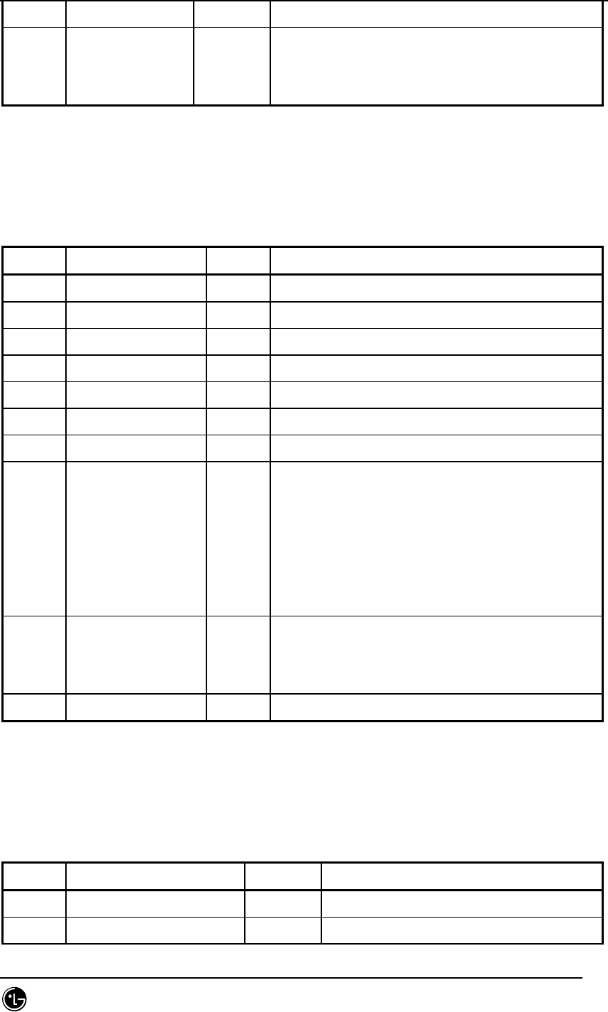
STAREX-IS BSM Manual
Page:796(877)
Issue:1.
0
SMD-011-PMA210
( LINK_AAL2(0), LINK_AAL5(1), LINK_TEST(2))
word16 link_bw[512] VC Link BandWidth
(Cell Bandwidth(~0x40) to be assigned to
Link)
7.5.2.5. St_re_can_net_cfg.dg
Table 7.5-6 St_re_can_net_cfg
Type N a m e default Remarks
byte can_net_shelf_id key full equip (MAX_CAN_NET_SHELF: 2)
byte can_net_slot_id key full equip (MAX_CAN_SLOT: 22)
byte equip ‘0’
byte bd_type Network Board Type
byte no_sub # of Sub Device
byte no_link # of Physical Link
byte hw_ctrl HW Reset : 0(Init), 1, 2, 3 added
byte link_type[MAX_LIN
K]
1 Physical Link Type : STM1, E1,...(MAX_LINK:
64)
LINK_TYPE_NONE(0),LINK_TYPE_STM1(1),LINK_TYP
E_STM12(2),
LINK_TYPE_STM14(3), LINK_TYPE_E1(4),
LINK_TYPE_T1(5)
byte sub_type[MAX_SUB] Sub Device Type (MAX_SUB : 16)
SBTYPE_NONE(0), SBTYPE_APC(1),
SBTYPE_APPD(2)
byte sub_id[MAX_SUB] Sub Device ID (MAX_SUB : 16)
7.5.2.6. St_re_can_net_data.dg
Table 7.5-7 St_re_can_net_data
Type N a m e default Remarks
byte dummy key
byte cn_id msc_no Core Network ID
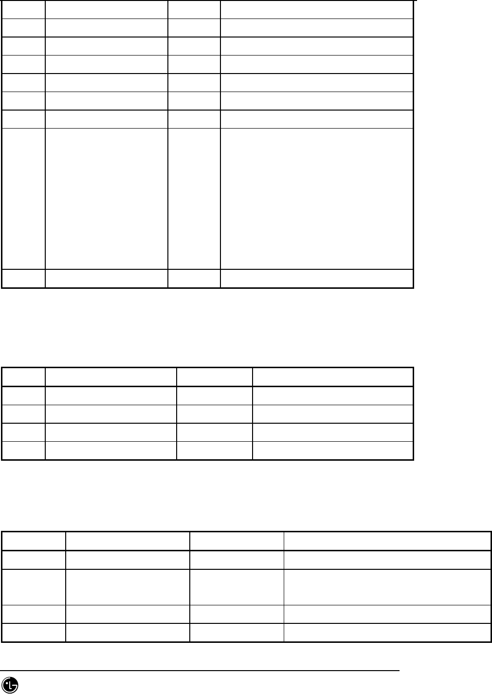
STAREX-IS BSM Manual
Page:797(877)
Issue:1.
0
SMD-011-PMA210
byte no_addr_hdr ATM Address Header Len
byte reserved[2]
byte rnc_equip[MAX_RNC] rnc_eqp RNC Equipage
byte atm_addr_hdr[20] ATM Address Header
byte rnc_conn_type[MAX_RNC] RNC Connectino ID
byte atsa_conn_type[12] ATSA Connection ID
word32 rnc_addr[MAX_RNC] RNC NCP Network Address
word32 camu_addr[16] CAMU Device Network Addr.
(0 : ASCA_A, 1 : ASCA_B, 2 : ASIA0_A,
3 : ASIA0_B, 4 : ASIA1_A, 5 : ASIA1_B
6 : ASIA2_A, 7 : ASIA2_B, 8 :
ASIA3_A, 9 : ASIA3_B, 10 : AOTA0,
11 : AOTA1,
12 : AOTA2, 13 : AOTA3, 14 : ATSA0,
15 : ATSA1)
byte reserved[8]
7.5.2.7. St_re_can_iur_con.dg
Table 7.5-8 St_re_can_iur_con
Type N a m e default Remarks
byte rnc_id key full equip
word32 start_aal2_vc_id[MAX_RNC] See *1 AAL2 Start VC Id
word16 no_aal2_vc 32 Number of AAL2 VCs
word16 reserved
7.5.2.8. St_re_can_rnc5_con.dg
Table 7.5-9 St_re_can_rnc5_con
Data Type N a m e default Remarks
byte dummy key
word32 start_aal5_vc_id[2] [10/32] = 0xA0020
[12/32] = 0xC0020
AAL5 Start VC Id
word16 no_aal5_vc 8192 Number of AAL5 VCs
word16 reserved

STAREX-IS BSM Manual
Page:798(877)
Issue:1.
0
SMD-011-PMA210
7.5.3. PNP ONLY
7.5.3.1. St_re_cand_node.dg
Table 7.5-10 St_re_cand_node
Data Type N a m e default Remarks
byte card_id key full equip (MAX_ATM_CARD:5)
byte link_id key full equip (MAX_ATM_LINK:32)
byte equip LINK_NOT_EQUIP(0), LINK_EQUIP(1)
byte link_type 1 ATM Link Type STM-1,STM-4,Cell Bus
(LINK_TYPE_NONE(0),LINK_TYPE_STM1(1),
LINK_TYPE_STM12(2),
LINK_TYPE_STM14(3), LINK_TYPE_E1(4),
LINK_TYPE_T1(5))
byte link_status 1 ATM Link Acktivity Init/Active/Block
(LINK_STS_NONE(0), LINK_STS_ACTIVE(1),
LINK_STS_ONL_BLOCK(2),
LINK_STS_MMC_BLOCK(3))
byte connect_typ
e
End-User’s own ID connected to Link (see
Appendix Connection ID)
byte fabric_no Switch Fabric No.( Index(0~8) of all
APCs)
(0:ASCA APC0, 1:ASIA0 APC0, 2:ASIA0 APC1,
3:ASIA1 APC0, 4:ASIA1 APC1, 5:ASIA2 APC0,
6: ASIA2 APC1, 7:ASIA3 APC0, 8 : ASIA3
APC1)
byte reserved[7]
7.5.3.2. St_re_pcf_node.dg
Table 7.5-11 St_re_pcf_node
Type N a m e Default Remarks
byte pcf_id key full equip (MAX_PCF_BLK:6)

STAREX-IS BSM Manual
Page:799(877)
Issue:1.
0
SMD-011-PMA210
byte link_id key full equip (MAX_SUB_LINK:32)
byte equip Number of
pcf
Equip as below
LINK_NOT_EQUIP(0), LINK_EQUIP(1)
byte link_type 1 ATM Link Type STM-1,STM-4,Cell Bus
LINK_TYPE_NONE(0), LINK_TYPE_STM1(1),
LINK_TYPE_STM12(2),
LINK_TYPE_STM14(3), LINK_TYPE_E1(4),
LINK_TYPE_T1(5)
byte link_status 1 ATM Link Acktivity Init/Active/Block
LINK_STS_NONE(0), LINK_STS_ACTIVE(1),
LINK_STS_ONL_BLOCK(2), LINK_STS_MMC_BLOCK(3)
byte connect_type Default 1
below.
Node Connection ID: End-User’s own ID
connected to Link
byte fabric_no 0 Switch Fabric No. Index(0~8) of all APCs
0 : BCRA APC0
byte reserved[7]
7.5.3.3. St_re_cand_addr.dg
Table 7.5-12 St_re_cand_addr
Type N a m e Default Remarks
byte shelf_id key full equip (MAX_CAN_SHELF: 4)
byte slot_id key full equip (MAX_CAN_SLOT: 22)
byte equip ‘0’
byte bd_type Processor/Device Board Type
PBA’s own number (not yet set)
byte no_sub Sub Processor Number In case of Sub processor
had IP
Nu,ber of processors mounted
byte reserved
word32 addr[MAX_SUB
]
MAX_SUB: 8

STAREX-IS BSM Manual
Page:800(877)
Issue:1.
0
SMD-011-PMA210
7.5.3.4. St_re_cand_pvc.dg
Table 7.5-13 St_re_cand_pvc
Type N a m e default Remarks
byte dummy key
word16 no_entry # of Valid Entries, number of defined
PVC information (~4096)
word16 reserved
byte equipage[4096] cand_pvc.inf
byte node_a[4096] Peer1 connection ID
byte sub_a[4096] Peer1 Logical Info
byte node_b[4096] Peer2 Connection ID
byte sub_b[4096] Peer2 Logical info
byte no_vc[4096] Number of VX to be used between Allocated
VC Number Peers
byte link_type[4096] Link Usage AAL1/2/5, Test
(LINK_AAL2(0), LINK_AAL5(1),
LINK_TEST(2))
word16 link_bw[4096] 0x100 VC Link Bandwidth (Cell Bandwidth(~0x40)
to be assigned to Link)
word32 vpci_a[4096] Peer1 VPI/VCI(Ingress VPCI)
word32 vpci_b[4096] Peer2 VPI/VCI(Egress VPCI)
7.5.3.5. St_re_pcf_pvc.dg
Table 7.5-14 St_re_pcf_pvc
Type N a m e Default Remarks
byte dummy key
word16 no_entry # of Valid Entries, number of defined PVC
information (~4096)
word16 reserved
byte equipage[512] pcf_pvc.inf
byte node_a[512] Peer1 connection ID
byte sub_a[512] Peer1 Logical Info

STAREX-IS BSM Manual
Page:801(877)
Issue:1.
0
SMD-011-PMA210
byte node_b[512] Peer2 Connection ID
byte sub_b[512] Peer2 Logical info
byte no_vc[512] Number of VCs to be used between Allocated
VC Number Peers
byte link_type[512] Link Usage AAL1/2/5, Test
LINK_AAL2(0), LINK_AAL5(1), LINK_TEST(2)
word16 link_bw[512] 0x100 Cell Bandwidth(~0x40) to be assigned to VC
Link Bandwidth-Link
word32 vpci_a[512] Peer1 VPI/VCI(Ingress VPCI)
word32 vpci_b[512] Peer2 VPI/VCI(Egress VPCI)
7.5.3.6. St_re_cand_svc.dg
Table 7.5-15 St_re_cand_svc
Type N a m e default Remarks
byte dummy key
word16 no_entry # of Valid Entries, number of defined PVC
info (~4096)
byte no_hdr Header Address Length Upper ATM Address
length
byte reserved
byte addr_hdr[20] Higher ATM address
byte equipage[512]
byte a_mask1[512][10] First address mask to be connected
byte addr1[512][10] First address to be connected
byte a_mask2[512][10] Second address mask to be connected
byte addr2[512][10] Second address to be connected
byte no_vc[512] Number of VCs to be used between peers
word32 atm_id1[512] vc id of first node (VPI:VCI)
word32 atm_id2[512] vc id of second node (VPI:VCI)
byte link_type[512] Link Usage(AAL1/2/5,Test)
( LINK_AAL2(0), LINK_AAL5(1), LINK_TEST(2))
word16 link_bw[512] VC Link BandWidth
(Cell Bandwidth(~0x40) to be assigned to

STAREX-IS BSM Manual
Page:802(877)
Issue:1.
0
SMD-011-PMA210
Link)
7.5.3.7. St_re_cand_net_cfg.dg
Table 7.5-16 St_re_cand_net_cfg
Type N a m e default Remarks
byte can_net_shelf_id key full equip (MAX_CAN_NET_SHELF: 2)
byte can_net_slot_id key full equip (MAX_CAN_SLOT: 22)
byte equip ‘0’
byte bd_type Network Board Type
byte no_sub # of Sub Device
byte no_link # of Physical Link
byte hw_ctrl HW Reset : 0(Init), 1, 2, 3 added
byte link_type[MAX_LIN
K]
1 Physical Link Type : STM1, E1,...(MAX_LINK:
64)
LINK_TYPE_NONE(0),LINK_TYPE_STM1(1),LINK_TYPE_
STM12(2),
LINK_TYPE_STM14(3), LINK_TYPE_E1(4),
LINK_TYPE_T1(5)
byte sub_type[MAX_SUB] Sub Device Type (MAX_SUB : 16)
SBTYPE_NONE(0), SBTYPE_APC(1), SBTYPE_APPD(2)
byte sub_id[MAX_SUB] Sub Device ID (MAX_SUB : 16)
7.5.3.8. St_re_cand_net_data.dg
Table 7.5-17 St_re_cand_net_data
Type N a m e default Remarks
byte dummy key
byte msc_id msc_no:0 MSC ID
byte reserved
byte pcf_equip[6] Number of
pcf equip
PCF Equipage
byte rnc_equip[MAX_RNC] Number of RNC equipage Header

STAREX-IS BSM Manual
Page:803(877)
Issue:1.
0
SMD-011-PMA210
rnc equip
byte pcf_conn_type[6][2] PCF Connectino ID
byte rnc_conn_type[MAX_RNC] RNC Connection ID
word32 pcp_addr[6]
word32 ncp_addr[MAX_RNC] RNC NCP Network Address
word32 camdu_addr[16] CAMD Device Network Addr.
(0 : ASCA_A, 1 : ASCA_B, 2 :
ASIA0_A, 3 : ASIA0_B, 4 : ASIA1_A,
5 : ASIA1_B 6 : ASIA2_A, 7 :
ASIA2_B, 8 : ASIA3_A, 9 : ASIA3_B,
10 : AOTA0, 11 : AOTA1,
12 : AOTA2, 13 : AOTA3, 14 : ATSA0,
15 : ATSA1)
7.5.3.9. St_re_cand_data5_con.dg
Table 7.5-18 St_re_cand_data5_con
Type N a m e Default Remarks
byte dummy key
word32 start_aal5_vc_id[MAX_RNC] [10/32] =
0xA0020
AAL5 Start VC Id.
word16 no_aal5_vc 8192 # of AAL5 VCs
word16 reserved
7.5.3.10. St_re_cand_pif5_con.dg
Table 7.5-19 St_re_cand_pif5_con
Type N a m e default Remakrs
byte Dummy key
word32 start_aal5_vc_id[11][2] AAL5 Start VC Id. (22 VPs)
word16 no_aal5_vc 512 # of AAL5 VCs
word16 Reserved

STAREX-IS BSM Manual
Page:804(877)
Issue:1.
0
SMD-011-PMA210
7.5.4. PCP ONLY
7.5.4.1. St_pdsn_addr_data_type
Table 7.5-20 St_pdsn_addr_data_type
Type Name default Remarks
byte dummy
byte no_of_pdsn 1 Number of equipped PDSN. Of
MAX_PDSN_NO, the number of correct
PDSN should be checked.
word32 pdsn_ip[MAX_PDSN_NO] PDSN IP MAX_PDSN_NO = 2 (temporal)
IP used by PDSN for Public
Networkinterface.
Home Agent IP. As several PDSNs can
be interfaced, extendibility is
considered.
If this value is “0”, regard each
RPP IP as PDSN IP.
byte no_of_pdsn_node[MAX_PDSN_
NO]
RPP number
mounted in
PDSN
STP configurqation includes 16 RPPs
in PDSN. It must include the
number of correct RPP in PDSN.
word32 pdsn_node_ip[MAX_PDSN_NO]
[MAX_NODE_NO]
RPP IPs MAX_NODE_NO = 20
PDSN RPP IP.
Insert IP of mounted RPP in order,
and insert the rest with 0.
byte ssk_value[MAX_PDSN_NO][MA
X_NODE_NO][16]
0 ssk value of PDSN_NODE that
interfaces with PCF.
Should be set per PDSN_NODE.
byte ssk_len[MAX_PDSN_NO][MAX_
NODE_NO];
0 ssk_val
length
ssk_value[] length
As value required for data call,
upon ssk_vale change, the length
should be calculated.
byte reserved[32] 0
7.5.4.2. St_PCF_timer_type
Table 7.5-21 St_PCF_timer_type

STAREX-IS BSM Manual
Page:805(877)
Issue:1.
0
SMD-011-PMA210
Type Name default Remarks
byte dummy
word16 Trp_lifetime 1800 PCF timer.
Range : 0 ~ 65,535
unit : 60sec
0x0000 = Release
0xFFFF = Infinite
word16 Tbsreq9 5000 PCF timer.
Range : 0 ~ 5000
Unit : 1msec
word16 Tdiscon9 5000 PCF timer.
Range : 0 ~ 5000
unit : 1msec
word16 Twaitho9 10000 PCF timer.
Range : 0 ~ 10000
Unit : 1msec
word16 Tregreq 5000 PCF timer.
Range : 0 ~ 5000
Unit : 1msec
word16 regreq_retry
_cnt
2 Registration Request message retransfer count
that PCF sends to PDSN.
Range : 0 ~ 20
Unit : frequency.
If no response from PDSN, a maximum of this
value should be resent.
byte reserved[32]
7.5.4.3. St_PCF_info_data_type
Table 7.5-22 St_PCF_info_data_type
TYPE Name default Remarks
byte dummy
byte identification_ty
pe
0 Upon A11 Signaling, identification field
type is determined.
0 : Time Stamp

STAREX-IS BSM Manual
Page:806(877)
Issue:1.
0
SMD-011-PMA210
1 : Nonce
word32 pcp_ip[MAX_PCF_SH
ELF][MAX_PCP_NO]
PCP IP,
PMP IP
MAX_PCF_SHELF = 2
MAX_PCP_NO = 2
PCP/PMP IP executing F/E interface.
[0][0] : PCP (Active)
[0][1] : PCP (Standby)
[1][0] : PMP (Active)
[1][1] : PMP (Standby)
word32 pip_ip[MAX_PCF_SH
ELF][MAX_PIP_NO]
PIP IPs MAX_PCF_SHELF = 2
MAX_PIP_NO = 11
PIP IP executing F/E interface.
word32 net_mask[MAX_PCF_
SHELF][MAX_PIP_NO
]
0 To be judged.
PLD add.
word32 default_gw[MAX_PC
F_SHELF][MAX_PIP_
NO]
0 Default Gateway.
To be determined. PLD added.
byte aaa_server_type 0 AAA server type
word16 sid System ID.
word16 nid Network ID.
Int32 ltm_off 18 Offset of local time from System time.
Thatis, local time offset from UTC.
Current local time = SYS_TIME - LP_SEC +
ltm_off
ltm_off = 18 ( 30 minutes per unit, that is,
9 hour difference)
* LP_SEC : Number of Leap seconds that
occurred since the start of System Time.
boolean day_lt 0 Daylight saving time flag (Summer time)
1 : day lighting saving time
0 : standard time
byte gre_seq_flag 0 1 : Used SEQ
0 : Not Used SEQ
word16 seq_cntl_timer 0 Upon PCF Sequence Control, timer that
waitsspecific seq_num ( buffering time )
unit ( msec )
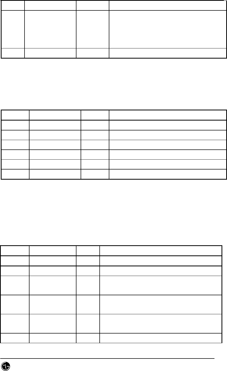
STAREX-IS BSM Manual
Page:807(877)
Issue:1.
0
SMD-011-PMA210
byte pkt_zone_id 0
byte UDR_MSID_TYPE 0 MSID Type in UDR that PDSN sends to AAA
Server
1 : IMSI
0 : MIN
byte reserved[32] 0
7.5.4.4. St_pifu_HW_Reset_data_type
Table 7.5-23 St_pifu_HW_Reset_data_type
Type Name default Remarks
byte shelf_id 0~1 key
byte pcp_isolation[11] 0 0: not isolation 1:isolation
byte bcra_isolation[2] 0 0: not isolation 1:isolation
byte fera_isolation[2] 0,1 0: not isolation.................................................
byte feta_isolation 0 0: not isolation 1:isolation
byte reserved[32] 0
7.5.5. CCP ONLY
7.5.5.1. St_fwdpwr_data_type.dg
Table 7.5-24 St_fwdpwr_data_type
Type N a m e default Remarks
byte bts_id full full equip
byte fer_id 0 ~ 1 Always Full equip
word16 slow_down_time 1600
(msec)
Gain down time. Applied during slow down
mode. (0 ~ 20000)
word16 fast_down_time 1600
(msec)
Gain down time. Applied during fast down mode.
(0 ~ 20000)
byte steps_till_fast 0 Number of slow down before switching to fast
down mode. (0 ~ 100)
byte slow_down_delta 1 Gain down delta. Applied during slow down

STAREX-IS BSM Manual
Page:808(877)
Issue:1.
0
SMD-011-PMA210
mode. (0 ~ 100)
byte fast_down_delta 1 Gain down delta. Applied during gast down
mode. (0 ~ 100)
byte nominal_gain 50 Nominal tx gain of primary/secondary
traffic. (0 ~ 127)
byte max_tx_gain 80 Max.tx gain of primary/secondary traffic
byte min_tx_gain 40 Min.tx gain of primary/secondary traffic.
byte fer_threshold 6 % Frame Error Rate threshold determines the gain
increase amount.(0 ~ 20)
byte big_up_delta 10 Gain increase delta. Applied when the forward
frame error rate contained in a PMRM exceeds
‘fer_threshold’.(0 ~ 100)
byte small_up_delta 5 Gain increase delta. Applied when the forward
frame error rate contained in a PMRM is less
than ‘fer_threshold’(0 ~ 100)
byte signal_delta_gain 96 Gain scaling factor of signaling traffic.
( 0 ~ 200 )
byte pcsc_delta_gain1 64 Gain scaling factor of PCSC bit.(1-cell)
byte pcsc_delta_gain2 96 Gain scaling factor of PCSC bit.(2-cell)
byte pcsc_delta_gain3 112 Gain scaling factor of PCSC bit.(3-cell)
byte reserved_byte[33] 0
7.5.5.2. St_13_fwdpwr_data_type.dg
Table 7.5-25 St_13_fwdpwr_data_type
Type N a m e default Remarks
byte bts_id full Full equip
byte fer_id 0 ~ 1 Always Full equip
word16 init_down_time 1000 Initial gain down time.(0 ~ 20000)
word16 max_down_time 4000 Maximum gain down time.(0 ~ 20000)
word16 min_down_time 200 Minimum gain down time.(0 ~ 20000)
word16 time_down_delta 200 Gain down time down delta. Applied in good
run state.(0 ~ 20000)
word16 time_up_delta 400 Gain down time up delta. Applied in erasure
run state.(0 ~ 20000)

STAREX-IS BSM Manual
Page:809(877)
Issue:1.
0
SMD-011-PMA210
word16 state_chg_thresh 250 Number of consecutive good frames brings
about good run state.(0 ~ 10000)
word16 erase_meas_frames 250 Cumulative erasure measuring period.(0 ~
65535)
byte cont_erase_eftv 2 Number of consecutive erasures brings about
tx gain increase. If 0, burst erasures have
no effect.(0 ~ 127)
byte cumul_erase_eftv 4 Number of cumulative erasures brings about
tx gain increase. If 0, non-burst erasures
have no effect.(0 ~ 127)
byte nominal_gain 50 Nominal tx gain of primary/secondary
traffic.(0 ~ 127)
byte max_tx_gain 100 Max.tx gain of primary/secondary traffic. (0
~ 127)
byte min_tx_gain 40 Min.tx gain of primary/secondary traffic. (0
~ 127)
byte gain_down_delta 1 Gain decrease delta (0 ~ 127)
byte big_up_delta 10 Gain increase delta. Applied when a gain-up
condition is encountered during ERASURE-
STATE. (0 ~ 100)
byte small_up_delta 5 Gain increase delta. Applied when a gain-up
condition is encountered during GOOD-STATE.
(0 ~ 100)
byte signal_delta_gain 96 Gain scaling factor of signaling traffic. (0
~ 200)
byte pcsc_delta_gain1 64 Gain scaling factor of PCSC bit.(1-cell)
(0 ~ 200)
byte pcsc_delta_gain2 96 Gain scaling factor of PCSC bit.(2-cell)
(0 ~ 200)
byte pcsc_delta_gain3 112 Gain scaling factor of PCSC bit.(3-cell)
(0 ~ 200)
byte reserved_byte[32] 0
7.5.5.3. St_revpwr_data_type.dg
Table 7.5-26 St_revpwr_data_type
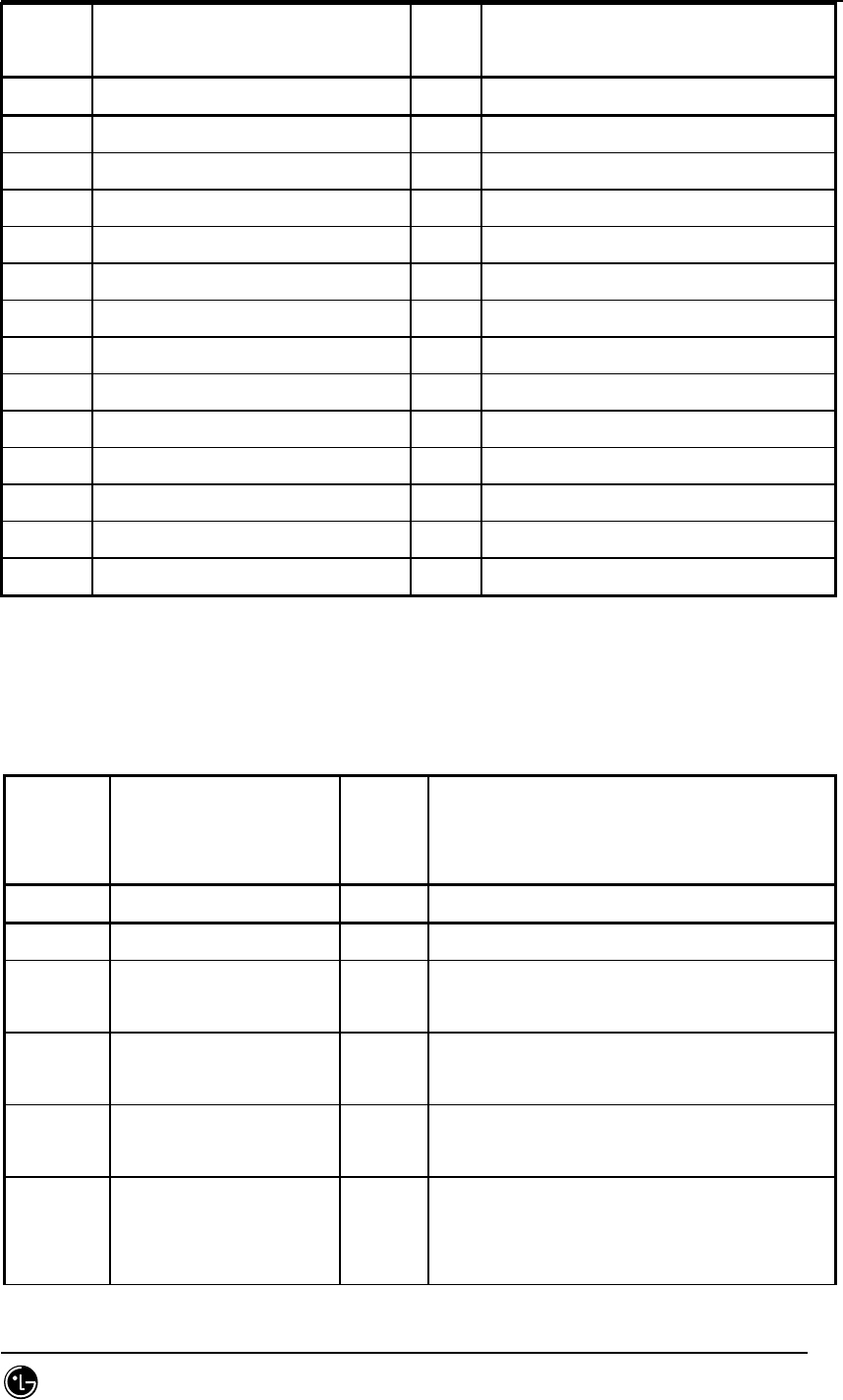
STAREX-IS BSM Manual
Page:810(877)
Issue:1.
0
SMD-011-PMA210
Type N a m e defaul
t
Remarks
byte bts_id full
byte fer_id 0 ~ 1 Always Full equip
word16 pnom (pwrctl_nominal) 19416 initial Eb/No(dB)
word16 pmax (pwrctl_max ) 23408 Maximum Eb/No(dB)
word16 pmin (pwrctl_min)) 8288 Minimum Eb/No(dB)
word16 pupf (pwrctl_up_full) 3072 Up for erase in full mode(dB)
short pfrr (pwrctl_full_run_reset) -2 Fulls until full mode(count value)
word16 pupe (pwrctl_up_erasure) 248 Up for erase in erase run(dB)
word16 pupel(pwrctl_up_erasure_little) 50 Up for erase(dB)
word16 pd (pwrctl_down) 48 Down for full(dB)
word16 pvd (pwrctl_var_down) 4 Down for variable(dB)
word16 pfw (pwrctl_full_wait) 2 Pause between up fulls(count value)
short perl (pwrctl_erasure_run_lim) 5 Erase until erase run(count value)
byte reserved_byte[32] 0
7.5.5.4. St_13_revpwr_data_type
Table 7.5-27 St_13_revpwr_data_type
Remarks
Type N a m e default
(As of 2000-3-6, on;y 1% used) fer_id :
0
byte bts_id full
byte fer_id 0 ~ 1 Always Full equip
word16 pnom (pwrctl_nominal) 19416 Initial pwrctl threshold value.
(up to 109048 at word32)
word16 pmax (pwrctl_max) 34304 Maximum pwrctl threshold value.
(up to 109048 at word32)
word16 pmin (pwrctl_min) 8288 Minimum pwrctl threshold value.
(up to 109048 at word32)
word16 rpc_big_up_delta 4608 Pwrctl threshold up delta. Applied when
a pwrctl-threshold-up condition is
encountered during ERASURE-STATE.

STAREX-IS BSM Manual
Page:811(877)
Issue:1.
0
SMD-011-PMA210
word16 rpc_small_up_delta 2304 Pwrctl threshold up delta. Applied when
a pwrctl-threshold-up condition is
encountered during GOOD-STATE.
byte rpc_non_erase_wait 2 Non-erasure rate waiting frame count
after increasing pwrctl threshold.
During the period, erasure rate frame
has no effect.
byte rpc_max_down_delta 48 Maximum pwrctl threshold down delta.
byte rpc_min_down-delta 2 Minimum pwrctl threshold down delta.
byte rpc_down_delta_inc_st
ep
1 Increment step size of pwrctl threshold
down delta up.
byte rpc_cont_erase_eftv 2 Number of consecutive erasures brings
about pwrctl-threshold-up. If 0, burst
erasures have no effect.
byte rpc_cumul_erase_eftv 3 Number of cumulative erasures during
rpc_erase_meas_frames brings about
pwrctl-threshold-up. If 0, non-burst
erasures have no effect.
word16 rpc_erase_meas_frames 450 Cumulative erasure measuring period.
word16 rpc_state_chg_thresh 250 Number of consecutive good frames
brings about GOOD-STATE.
byte reserved_byte[34] 0
7.5.5.5. St_SlpSts_data_type
Table 7.5-28 St_SlpSts_data_type
Type N a m e Default Remarks
BYTE SMP_ID full 0 ~ 4 SMP IDENTIFICATION
BYTE SLP_ID full 0 ~ 17 SLP IDENTIFICATION
BYTE SLP_STS 0 0: UNBLOCK 8: BLOCK
BYTE SLAVE_STS[4] 0 0: UNBLOCK 8: BLOCK
byte Rserved_byte[33] 0
7.5.5.6. St_VcpSts_data_type
Table 7.5-29 St_VcpSts_data_type
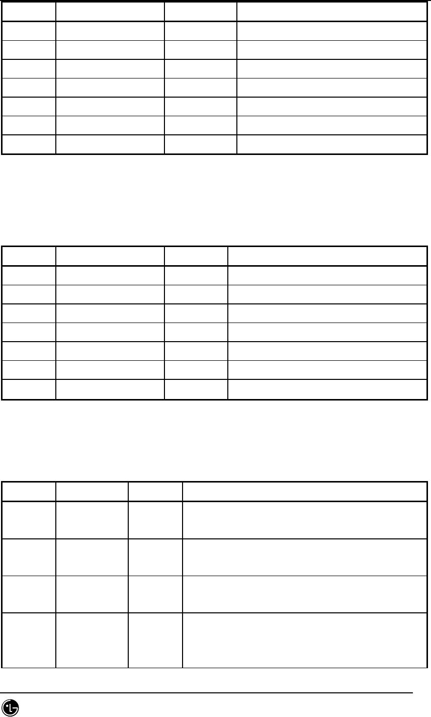
STAREX-IS BSM Manual
Page:812(877)
Issue:1.
0
SMD-011-PMA210
Type N a m e default Remarks
BYTE VMP_ID full 0 ~ 7 VMP IDENTIFICATION
BYTE VCP_ID full 0 ~ 15 VCP IDENTIFICATION
BYTE SHELF_TYPE 0 0: PHASE1 1: PHASE2
BYTE VCP_STS 0 0: UNBLOCK 8: BLOCK
BYTE VCP_SLAVE_STS[2] 0 0: UNBLOCK 8: BLOCK
BYTE VCE_STS[8] 0 0: UNBLOCK 8: BLOCK
byte reserved_byte[34] 0
7.5.5.7. St_Trunk_data_type
Table 7.5-30 St_Trunk_data_type
Type N a m e default Remarks
BYTE VMP_ID full 0 ~ 7 VMP IDENTIFICATION
BYTE VLIA_ID full 0 ~ 1 VLIA IDENTIFICATION
BYTE VLIA_STS 0 0: UNBLOCK 8: BLOCK
BYTE LINK_STS[16] 0 0: UNBLOCK 8: BLOCK
byte ts_sts[16][32] 0 0: UNBLOCK 8: BLOCK
byte ts_type[16][32] 0: Vocoder 1: NO7(ts being 16)
byte reserved_byte[33] 0
7.5.5.8. St_T1_Trunk_data_type
Table 7.5-31 St_T1_Trunk_data_type
Type N a m e default Remarks
byte btia_id 0 ~ 15 BTIA board identification
(board to connect T1 link)
byte T1_id 0 ~ 4 T1 link identification ( one BTIA holds
5 T1 links.)
byte ts_id 0 ~ 23 Time slot identification ( 1 T1 link holds 24
Time slots.)
byte type 0 ~ 1
0: used for vocoder assignment
1: current time slot is connected to
STF(Signaling Terminal Function) for No.7

STAREX-IS BSM Manual
Page:813(877)
Issue:1.
0
SMD-011-PMA210
byte sbp_no 0 ~ 14 sbp number of vocoder channel that is matched
to each time slot
byte svc_no 0 ~ 15 svc number of vocoder channel matched to each
time slot
byte vce_no 0 ~ 7 vocoder channel number matched to each time
slot
word cic Number matched to all time slots, that is,
each time slot’s own number.
byte dummy
byte reserved_byt
e[34] 0
7.5.5.9. St_Bsc_data_type
Table 7.5-32 St_Bsc_data_type
Type N a m e default Remarks
byte dummy_key
byte bsc_id 0 ~ 11 bsc identification
byte trunk_type 0 : E1 (LGT)
1 : T1 (NW)
word16 inactive_timer 30 MS inactive status judgement level
word16 dormant_timer 10 MS dormant status judgement level
byte bad_frame_time
byte pkt_zone Current default: 0
byte pcp_id Current default: 0 connected PCP ID
byte band_class
0(DCN)
1(1900Mgz)
4(1800Mhz)
band class of candidate frequency
800Mhz: 0
1800Mhz : 4 = domestic
1900Mhz: 1 = overseas
byte reserved_byte[31] 0
7.5.5.10. St_target_fer_service_type
Table 7.5-33 St_target_fer_service_type

STAREX-IS BSM Manual
Page:814(877)
Issue:1.
0
SMD-011-PMA210
Type N a m e default Remarks
byte Dummy 0
byte voice_8k 1 Basic Variable Rate (8K Voice)
byte loopback_8k 1 8K Loopback : IS-126
byte evrc 1 Enhanced Variable Rate Code
byte async 1
Asycronous Data(9.6 Kbps) : Provides Dial Up
Modem function and AT command, and subscriber
uses this for end-to-end communication or
accesses public data network.
byte g3fax 1
Group 3 Facsimile(9.6Kbps) : It added the
function of processing extension AT command
for FAX to Dial Up Modem so that subscriber
with FAX can exchange data with FAX
accommodated in PSTN.
byte sms 1
Short Message(Rate Set 1) : Exchanges SMS
between external device and PCS network or
between MS and Network.
byte ppp_pkt 1
Paket Data(Internet/ISO Protocol Stack)
PPP protocol stack is mounted on MS and
Network Layer.
Point-to-Point Packet Data Service
byte cdpp_pkt 1
Packet Data(CDPP Protocol Stack)
PPP protocol stack is mounted on MS and
Network Layer. Multiple Packet Service
byte loopback_13k 1 13K Loopback
byte stu_iii_tr 1
byte stu_iii_ntr 1
byte async_13k 1 Asycronous Data (14.4Kbps)
byte g3fax_13k 1 Group 3 Facsimile (14.4Kbps)
byte sms_13k 1 Short Message (Rate Set 2)
byte voice_13k 1 Basic Variable Rate (8K Voice)
byte is96_voice 1
byte markov_8k 1 Markov Call ( 8Kbps)
byte data 1
byte is96a_no 1 96A no quarter rate
byte markov_13k 1 Markov Call (14.4Kbps)

STAREX-IS BSM Manual
Page:815(877)
Issue:1.
0
SMD-011-PMA210
byte wll_offhook 1
byte rs1_markov 1 rate set 1 Markov Call
byte rs2_markov 1 rate set 2 Markov Call
byte fch_fer 1 RC3 data service
(0~31)
byte sch_fer 1 RC3 data service
(0~31)
byte dcch_fer 1 RC3 data service
(0~31)
byte Sch_loopback 0
byte Sch_loopback2 0
byte Reserved_byte[
31] 0
7.5.5.11. St_MAHHO_data_type
Table 7.5-34 St_MAHHO_data_type
Type N a m e default Remarks
byte bts_id full
byte sector_id full
byte border_flag 0: Off, 1: On
byte band_class
0(DCN)
1(1900Mgz)
4(1800Mhz)
band class of candidate frequency
800Mhz: 0
1800Mhz : 4 = domestic
1900Mhz: 1 = overseas
byte Num_cdma_freq Number of candidate frequency
word16 cdma_freq[MAX_CDMA_CH
] Candidate frequency (cdmach_num)
byte sf_total_ec_thresh 11111(bin)
As threshold of total Ec value
regarding Serving Frequency, this
determines whether to search
candidate frequency.
byte sf_total_ec_io_thresh 26
As threshold of total Ec/Io value
regarding Serving Frequency, this
determines whether to search
candidate frequency.

STAREX-IS BSM Manual
Page:816(877)
Issue:1.
0
SMD-011-PMA210
If total Ec/Io value is lower than
total threshold regarding serving
frequency, it does not search the
pilot of Candidate Frequency.
byte diff_rx_pwr_thresh 0
As power difference threshold
between received serving frequency
and candidate frequency, this
determines whether to search
candidate frequency.
byte min_total_pilot_ec_io 0 Ec/Io threshold of active set of
candidate frequency
byte cf_t_add 26
Threshod to add pilot to acticve
set of candidate frequency.
If of pilots that belondg to
neighbor set of Candidate
Frequency, there is a pilot that
has better Ec/Io than cf_t_add, it
is reported to BS through Candidate
Frequency Search Report.
byte tf_wait_time 30
After transition to target
frequency, waiting time to receive
good frame( 80ms unit)
30 2.4 second
byte cf_srch_win_n 9
Basic Search Window for candidate
frequency neighbor set ( it uses
teg same value as that of search
window to existing system parameter
message)
byte cf_srch_win_r 10 Basic search window for candidate
frequency Remaining Set
byte reserved_byte[35] 0
7.5.5.12. St_location_para_type
Table 7.5-35 St_location_para_type

STAREX-IS BSM Manual
Page:817(877)
Issue:1.
0
SMD-011-PMA210
Type N a m e default Remarks
byte bts_id full
byte sector_id full
byte action_time_frame
After set Action time, frame unit
duration until first PUF probe. Before
PUF pulse transfer, duration sent with
nominal power
byte puf_setup_size power control group unit.
byte puf_pulse_size Duration that MS sends PUF pulse. Power
control group unit.
word16 puf_interval Interval between PUF Probes. frame unit
byte puf_init_pwr Initial PUF Probe power. in units of dB
byte puf_pwr_step PUF pulse power increase. in units of dB
byte total_puf_probes Total PUF prove number
byte max_pwr_puf Max. PUF Probe number that can be
transmitted with max. Tx power
byte reserved_byte[33] 0
7.5.5.13. St_pwr_cntl_para_type
Table 7.5-36 St_pwr_cntl_para_type
Type N a m e default Remarks
byte bts_id full
byte fer_id 0 ~ 30
byte pwr_cntl_step step size of forward link closed
loop power control
byte fpc_mode 0
operation mode of forward link
closed loop power control
It should be the same as
fpc_punc_mode of
St_Chip_pwr_cntl_para_data.
byte fpc_fch_init_setpt
initial Value of Forward
Fundamental Channel Outer Loop
Eb/Nt setpoint (hereinafter

STAREX-IS BSM Manual
Page:818(877)
Issue:1.
0
SMD-011-PMA210
FFCOLS). 0.125dB unit
byte fpc_fch_min_setpt Minimum value of FFCOLS. 0.125dB
unit
byte fpc_fch_max_setpt FFCOLS’s Maximum value. 0.125dB
unit
byte fpc_dcch_init_setpt
Forward Dedicated Control Channel
Outer Loop Eb/Nt setpoint
(hereinafter FDCCOLS) initial
value. 0.125dB
byte fpc_dcch_min_setpt FDCCOLS’s Minimum value. 0.125dB
byte fpc_dcch_max_setpt FDCCOLS’s Maximum value. 0.125dB
byte fpc_sch_init_setpt
Forward Supplemental Channel Outer
Loop Eb/Nt setpoint(FSCOLS)
initial value. 0.125dB
byte fpc_sch_min_setpt FSCOLS’s Minimum value. 0.125dB
byte fpc_sch_max_setpt FSCOLS’s Maximum value. 0.125dB
byte fpc_setpt_thresh Forward link Power control
Setpoint Threshold Value. 0.125dB
byte fpc_setpt_thresh_sch
Forward Supplemental Channel
Power control Setpoint Threshold
Value. 0.125dB
byte fch_chan_adj_gain
Channel Gain adjustment value for
Reverse Fundamental Channel.
Complement of 2 in 0.125dB unit.
byte dcch_chan_adj_gain
Channel Gain adjustment value for
Reverse Dedicated Control Channel.
Complement of 2 in 0.125dB unit.
byte sch0_chan_adj_gain
Channel Gain adjustment value for
Reverse Supplemental Channel 0.
Complement of 2 in 0.125dB unit.
byte sch1_chan_adj_gain
Channel Gain adjustment value for
Reverse Supplemental Channel 1.
Complement of 2 in 0.125dB unit.
byte rl_att_adj_gain_1500[2]
index 0: not using Reverse Pilot
index 1: using Reverse Pilot
20ms frame, 1500bps Reverse Link

STAREX-IS BSM Manual
Page:819(877)
Issue:1.
0
SMD-011-PMA210
Attribute Adjustment gain value.
byte rl_att_adj_gain_2700[2] 20ms frame, 2700bps Reverse Link
Attribute Adjustment gain value.
byte rl_att_adj_gain_4800[2] 20ms frame, 4800bps Reverse Link
Attribute Adjustment gain value.
byte rl_att_adj_gain_9600[2] 20ms frame, 9600bps Reverse Link
Attribute Adjustment gain value.
byte rl_att_adj_gain_1800[2] 20ms frame, 1800bps Reverse Link
Attribute Adjustment gain value.
byte rl_att_adj_gain_3600[2] 20ms frame, 3600bps Reverse Link
Attribute Adjustment gain value.
byte rl_att_adj_gain_7200[2] 20ms frame, 7200bps Reverse Link
Attribute Adjustment gain value.
byte rl_att_adj_gain_14400[2] 20ms frame, 14400bps Reverse Link
Attribute Adjustment gain value.
byte norm_att_gain_9600_5ms[2] 5ms frame, 9600bps Reverse Link
Attribute Adjustment gain value.
byte rl_att_adj_gain_19200[2][2]
2nd index 0:
2dn index 1: Turbo Encoding
20ms frame, 19200bps Reverse Link
Attribute Adjustment gain
byte rl_att_adj_gain_38400[2][2] 20ms frame, 38400bps Reverse Link
Attribute Adjustment gain
byte rl_att_adj_gain_76800[2][2] 20ms frame, 76800bps Reverse Link
Attribute Adjustment gain
byte rl_att_adj_gain_153600[2][2] 20ms frame, 153600bps Reverse Link
Attribute Adjustment gain
byte rl_att_adj_gain_307200[2][2] 20ms frame, 307200bps Reverse Link
Attribute Adjustment gain
byte rl_att_adj_gain_614400[2][2] 20ms frame, 614400bps Reverse Link
Attribute Adjustment gain
byte rl_att_adj_gain_28800[2][2] 20ms frame, 28800bps Reverse Link
Attribute Adjustment gain
byte rl_att_adj_gain_576600[2][2] 20ms frame, 576600bps Reverse Link
Attribute Adjustment gain
byte rl_att_adj_gain_115200[2][2] 20ms frame, 115200bps Reverse Link

STAREX-IS BSM Manual
Page:820(877)
Issue:1.
0
SMD-011-PMA210
Attribute Adjustment gain
byte rl_att_adj_gain_230400[2][2] 20ms frame, 230400bps Reverse Link
Attribute Adjustment gain
byte rl_att_adj_gain_460800[2][2] 20ms frame, 460800bps Reverse Link
Attribute Adjustment gain
byte rl_att_adj_gain_1036800[2][2] 20ms frame, 1036800bps Reverse
Link Attribute Adjustment gain
byte fpc_subchan_gain
byte rl_gain_adj
byte rlgain_traffic_pilot
byte rlgain_sch_pilot
byte reserved_byte[33] 0
7.5.5.14. St_sch_param_data
Table 7.5-37 St_sch_param_data
Type N a m e default Remarks
byte bts_id full
byte sector_id full
byte sch_t_add 22 Regarding MDR handoff, t_add that is only
appied as to Supplemental Code Channel
byte sch_t_drop 26 Regarding MDR handoff, t_drop that is only
applied as to Supplemental Code Channel
byte t_mulchan threshold offset of Nghbr Pilot strength.
0.5dB step from 0.5dB to 4.0dB
byte begin_preamble Preamble Frame number sent at the
beginning of Reverse Supplemental (Code)
Channel transfer
byte resume_preamble Preamble Frame number sent upon
retransfer of Reverse Supplemental (Code)
Channel
byte ps_min_delta Parameter necessary when operating in
such mode as MS sending Pilot Strength
Measurement Mini Message(PSMMM) whenever

STAREX-IS BSM Manual
Page:821(877)
Issue:1.
0
SMD-011-PMA210
Active Set order changes. As threshold
necessary so that MS judges PSMMM
transfer, this is necessary upon such
mode as MS sending PSMMM whenever the
order of active set changes.
byte order_interval Interval to report the difference between
two pilot strengths through PSMMM. in
units of 20ms
byte num_pilots Parameter necessary for MS to send PSMMM.
Pilot number reported through PSMMM
byte periodic_interval Interval that MS sends PSMMM. in units of
20ms
byte ps_floor_high Based on threshold, high water mark value
set as to lower bound.
byte ps_floor_low Based on threshold, low water mark
valueset as to lower bound
byte ps_ceiling_high Based on threshold, high water mark value
set as to upper bound
byte ps_ceiling_low Based on threshold, low water mark value
set as to upper bound.
byte threshold_interval Based on threshold, PSMMM transfer
interval. in units of 20ms
byte t_slotted Parameter included in In Traffic System
Parameters Message
byte reserved_byte[35]
7.5.5.15. St_IOS_para_data
Table 7.5-38 St_IOS_para_data
Type N a m
e
default Remarks
byte dummy key
byte T1 55 (0~255) Facilities Management(sec)
byte T2 60 (0~255) Facilities Management(sec)
byte T4 60 (0~255) Facilities Management(sec)

STAREX-IS BSM Manual
Page:822(877)
Issue:1.
0
SMD-011-PMA210
byte T5 60 (0~255) Facilities Management(sec)
byte T6 75 (0~255) Facilities Management(sec)
byte T7 10 (0~255) Handoff(sec)
byte T9 10 (0~255) Handoff(sec)
byte T10 5 (0~99) Handoff(sec)
byte T12 60 (0~255) Facilities Management(sec)
byte T13 55 (0~255) Facilities Management(sec)
byte T16 60 (0~255) Facilities Management(sec)
byte T20 5 (0~99) Call Processing(sec)
byte T30 5 (0~99) Call Processing(sec)
byte T40 5 (0~99) Call Processing(sec)
byte T50 60 (0~255) Handoff(sec)
byte T52 90 (0~255) Handoff(sec)
byte T60 5 (0~99) Supplementary Services(sec)
byte T61 5 (0~99) Supplementary Services(sec)
byte T62 5 (0~99) Supplementary Services(sec)
byte T63 5 (0~99) Supplementary Services(sec)
word32 T300 1500 (0~990) Call Processing (msec)
byte T301 30 (0~60) CallProcessing(sec)
byte T302 5 (0~99) Call Processing(sec)
byte T303 6 (0~99) Call Processing(sec)
byte T306 5 (0~99) Call Processing(sec)
byte T307 6 (0~99) Call Processing(sec)
byte T308 5 (0~99) Call Processing(sec)
byte T309 5 (0~90) Facilities Management (sec)
word16 T311 1000 (0~50) Call Processing (msec)
byte T312 5 (0~99) Call Processing(sec)
byte T313 2 (0~99) Call Processing(sec)
byte T315 5 (0~99) Call Processing(sec)
byte T316 5 (0~99) Call Processing(sec)
byte T325 5 (0~99) Call Processing(sec)
byte T326 5 (0~99) Call Processing(sec)
byte T777 90 (0~255) Handoff (sec)
byte T778 15 (0~255) Handoff (sec)
byte T787 90 (0~255) Handoff (sec)
byte T789 10 (0~60) Handoff (sec)

STAREX-IS BSM Manual
Page:823(877)
Issue:1.
0
SMD-011-PMA210
byte T790 10 (0~60) Handoff (sec)
byte T3113 5 (0~99) Call Processing (sec)
byte T3210 30 (0~99) Mobility Management (sec)
byte T3220 10 (0~99) Mobility Management (sec)
byte T3230 5 (0~99) Call Processing (sec)
byte T3240 5 (0~99) Mobility Management (sec)
byte T3260 30 (0~99) Mobility Management (sec)
byte T3270 5 (0~99) Mobility Management (sec)
byte T3271 15 (0~99) Mobility Management (sec)
byte T3272 5 (0~99) Mobility Management (sec)
byte T3280 15 (0~99) Call Processing (sec)
byte TA8_Setup 4 (0~99) A8,A9 Interfaces (sec)
word16 Tacm 500 (0~1000) A3,A7 Interfaces (msec)
word16 Talc9 500 (0~1000) A8,A9 Interfaces (msec)
word16 Tald9 500 (0~1000) A8,A9 Interfaces (msec)
word16 Tbstact 600 (0~1000) A3,A7 Interfaces (msec)
word16 Tbstcom 100 (0~1000) A3,A7 Interfaces (msec)
word16 Tchanstat 500 (0~1000) A3,A7 Interfaces (msec)
word16 Tconn3 500 (1~1000) A3,A7 Interfaces (msec)
word16 Tdiscon3 500 (1~1000) A3,A7 Interfaces (msec)
byte Tdrptgt 5 (1~10) A3,A7 Interfaces (sec)
byte Ttgtrmv 5 (1~10) A3,A7 Interfaces (sec)
word16 Thoreq 1000 (0~50) A3,A7 Interfaces (msec)
byte Tpaca1 5 (0~99) Call Processing (sec)
byte Tpaca2 5 (0~99) Call Processing (sec)
word16 Tpcm 1000 (0~20) A3,A7 Interfaces (msec)
byte Tphysical 1 (0~10) A3,A7 Interface (sec)
word16 Trel9 1000 (0~50) A8,A9 Interface (msec)
byte reserved_by
te[35]
7.5.5.16. St_Vcbu_HW_Reset_data_type
Table 7.5-39 St_Vcbu_HW_Reset_data_type
Type N a m e default Remarks
Byte VMP_ID 0 ~ 7 VMP IDENTIFICATION

STAREX-IS BSM Manual
Page:824(877)
Issue:1.
0
SMD-011-PMA210
Byte EquipPage According to
Equip status
0: Not Equip 1: Equip
Byte VMP_Isolation 0 0: not_isolation 1: isolation
Byte VCP_Isolation[16] 0 0: not_isolation 1: isolation
Byte VLIA_Isolation[2] 0 0: not_isolation 1: isolation
Byte reserved_byte[34] 0
7.5.5.17. St_Slbu_HW_Reset_data_type
Table 7.5-40 St_Slbu_HW_Reset_data_type
Type N a m e Default Remarks
Byte SMP_ID 0 ~ 4 SMP IDENTIFICATION
Byte EquipPage According to
Equip status
0: Not Equip 1: Equip
Byte SMP_Isolation 0 0: not_isolation 1: isolation
Byte SLP_Isolation[20] 0 0: not_isolation 1: isolation
Byte rserved_byte[33] 0
7.5.6. NCP ONLY
7.5.6.1. St_re_atm_node.dg
Table 7.5-41 St_re_atm_node
Type N a m e default Remarks
byte card_id key full equip (MAX_ATM_CARD:5)
byte link_id key full equip (MAX_ATM_LINK:32)
byte equip As many as Node Config below Equip 1: Equip,
0:Not-Equip
byte link_type 1 STM-1, STM-4, Cell Bus
(LINK_TYPE_NONE(0),LINK_TYPE_STM1(1),LINK_TYPE_S
TM12(2),
LINK_TYPE_STM14(3), LINK_TYPE_E1(4),
LINK_TYPE_T1(5))
byte link_status 1 Link status
LINK_STS_NONE(0), LINK_STS_ACTIVE(1),

STAREX-IS BSM Manual
Page:825(877)
Issue:1.
0
SMD-011-PMA210
LINK_STS_ONL_BLOCK(2), LINK_STS_MMC_BLOCK(3)
byte connect_type End-User’s own ID connected to Link(see Appendix
Connection ID)
byte fabric_no Fabric is a serial number of APC.
Index(0~8) of total APCs
0 : ASCA APC0, 1 : ASIA0 APC0, 2 : ASIA0 APC1,
3 : ASIA1 APC0, 4 : ASIA1 APC1, 5 : ASIA2 APC0,
6 : ASIA2 APC1, 7 : ASIA3 APC0, 8 : ASIA3 APC1
byte reserved[7]
7.5.6.2. St_re_slb_node.dg
Table 7.5-42 St_re_slb_node
Type N a m e default Remarks
byte smp_id key full equip MAX_SLB:5
byte link_id key full equip (MAX_SUB_LINK:32)
byte equip smp
number
As many as Node Config below, Equip 1: Equip,
0:Not-Equip
byte link_type 1 STM-1, STM-4, Cell Bus
(LINK_TYPE_NONE(0),LINK_TYPE_STM1(1),LINK_TYPE_S
TM12(2),
LINK_TYPE_STM14(3), LINK_TYPE_E1(4),
LINK_TYPE_T1(5))
byte link_status 1 Link status
LINK_STS_NONE(0), LINK_STS_ACTIVE(1),
LINK_STS_ONL_BLOCK(2), LINK_STS_MMC_BLOCK(3)
byte connect_type End-User’s own ID connected to Link (see
Appendix Connection ID)
byte fabric_no 0 Index(0~8) of total APCs
0 : SLMA APC0
byte reserved[7]
7.5.6.3. St_re_vcb_node.dg
Table 7.5-43 St_re_vcb_node

STAREX-IS BSM Manual
Page:826(877)
Issue:1.
0
SMD-011-PMA210
Type N a m e Default Remarks
byte vmp_id Key full equip MAX_VCB:8
byte link_id key full equip (MAX_SUB_LINK:32)
byte equip Vmp
number
As many as Node Config below, Equip 1: Equip,
0:Not-Equip
byte link_type 1 STM-1, STM-4, Cell Bus
(LINK_TYPE_NONE(0),LINK_TYPE_STM1(1),LINK_TYPE
_STM12(2),
LINK_TYPE_STM14(3), LINK_TYPE_E1(4),
LINK_TYPE_T1(5))
byte link_status 1 Link status
LINK_STS_NONE(0), LINK_STS_ACTIVE(1),
LINK_STS_ONL_BLOCK(2), LINK_STS_MMC_BLOCK(3)
byte connect_type End-User’s own ID connected to Link
(see Appendix Connection ID)
byte fabric_no 0 Index(0~8) of total APCs
0 : VCMA APC0
byte reserved[7]
7.5.6.4. St_re_alb_node.dg
Table 7.5-44 St_re_alb_node
Type N a m e default Remarks
byte alma_id key full equip (MAX_ALMA:2)
byte link_id key full equip (MAX_ALS_LINK:16)
byte equip As many as Node Config below, Equip 1: Equip,
0:Not-Equip
byte link_type 1 STM-1, STM-4, Cell Bus
(LINK_TYPE_NONE(0),LINK_TYPE_STM1(1),LINK_TYPE
_STM12(2),
LINK_TYPE_STM14(3), LINK_TYPE_E1(4),
LINK_TYPE_T1(5))
byte link_status 1 Link status
LINK_STS_NONE(0), LINK_STS_ACTIVE(1),
LINK_STS_ONL_BLOCK(2), LINK_STS_MMC_BLOCK(3)

STAREX-IS BSM Manual
Page:827(877)
Issue:1.
0
SMD-011-PMA210
byte connect_type End-User’s own ID connected to Link
(see Appendix Connection ID)
byte fabric_no 0 Index(0~8) of total APCs
0 : ALMA APC0
byte reserved[7]
7.5.6.5. St_re_bs_atm_node.dg
Table 7.5-45 St_re_bs_atm_node
Type N a m e default Remarks
byte Bs_id key full equip MAX_BS:48
byte link_id key full equip (MAX_SUB_LINK:32)
byte equip bs
number
As many as Node Config below, Equip 1: Equip,
0:Not-Equip
byte link_type 1 STM-1, STM-4, Cell Bus
(LINK_TYPE_NONE(0),LINK_TYPE_STM1(1),LINK_TYPE
_STM12(2),
LINK_TYPE_STM14(3), LINK_TYPE_E1(4),
LINK_TYPE_T1(5))
byte link_status 1 Init/Active/Block
LINK_STS_NONE(0), LINK_STS_ACTIVE(1),
LINK_STS_ONL_BLOCK(2),
LINK_STS_MMC_BLOCK(3))
byte connect_type End-User’s own ID connected to Link
(see Appendix Connection ID)
byte Fabric_no 0 index(0~8) of total APCs
0 : BCRA APC0
byte reserved[7]
7.5.6.6. St_re_rnc_bs_trunk.dg
Table 7.5-46 St_re_rnc_bs_trunk
Data
Type N a m e default Remarks
byte alma_id key full equip MAX_ALMA: 2

STAREX-IS BSM Manual
Page:828(877)
Issue:1.
0
SMD-011-PMA210
byte alpa_id key full equip MAX_ALPA: 5
byte link_id key full equip MAX_ALS_LINK: 16
byte equip BS
dependent
LINK_NOT_EQUIP(0), LINK_EQUIP(1)
byte link_type 1 E1, T1, STM-1
(LINK_TYPE_NONE(0),LINK_TYPE_STM1(1),LINK_TY
PE_STM12(2),
LINK_TYPE_STM14(3), LINK_TYPE_E1(4),
LINK_TYPE_T1(5))
byte link_status 1 LINK_STS_NONE(0), LINK_STS_ACTIVE(1),
LINK_STS_ONL_BLOCK(2), LINK_STS_MMC_BLOCK(3)
byte bs_id Link Peer BS/BTS ID
byte alloc_type 1 PVC Active/PVC Standby/SVC
- ALLOC_NONE(0),ALLOC_PVC_ACT(1),
ALLOC_PVC_STB(2), ALLOC_SVC(3))
byte peer_lica_no BS Lica Index (0, 1, 2)
byte peer_lica_li
nk_no
BS Lica Link Index (0~15)
byte peer_status Init/Active/Block
LINK_STS_NONE(0), LINK_STS_ACTIVE(1),
LINK_STS_ONL_BLOCK(2),
LINK_STS_MMC_BLOCK(3))
word32 aal2_vpci AAL2 VPI/VCI
word32 reserved
7.5.6.7. St_re_rnc_addr.dg
St_re_rnc_addr
Type N a m e default Remarks
byte shelf_id key full equip (MAX_RNC_SHELF: 20)
byte slot_id key full equip (MAX_RNC_SLOT: 22)
byte equip ‘0’ Equit/Not Equip
byte Bd_type Processor/Device Board Type(TBD)
byte No_sub Number of processors to be mounted
byte reserved Not Used

STAREX-IS BSM Manual
Page:829(877)
Issue:1.
0
SMD-011-PMA210
word32 addr[8] Each Processor IP Address
7.5.6.8. St_re_bs_addr.dg
St_re_bs_addr
Type N a m e default Remarks
byte bs_id key full equip MAX_BS: 48
byte shelf_id key full equip (MAX_BS_SHELF: 12)
byte slot_id key full equip (MAX_BS_SLOT: 22)
byte equip ‘0’ Equit/Not Equip
byte bd_type Processor/Device Board Type(TBD)
byte no_sub Number of processors mounted
byte reserved Not Used
word32 addr[8] Each Processor IP Address
7.5.6.9. St_re_atm_pvc.dg
Table 7.5-47 St_re_atm_pvc
Type N a m e default Remarks
byte dummy key
word16 no_entry # of Valid Entries, defined PVC information
number (~4096)
word16 reserved
byte equipage[4096] Equip Flag
byte node_a[4096] Peer1 connection ID (Ingress Node Conn. ID)
byte sub_a[4096] Peer1 Logical Info
byte node_b[4096] Peer2 Connection ID (Egress Node Conn. ID)
byte sub_b[4096] Peer2 Logical info
byte no_vc[4096] Number of VC to be used between Allocated VC
Number Peers
byte link_type[4096] Link
LINK_AAL2(0), LINK_AAL5(1), LINK_TEST(2)
word16 link_bw[4096] 0x100 VC Link Bandwidth
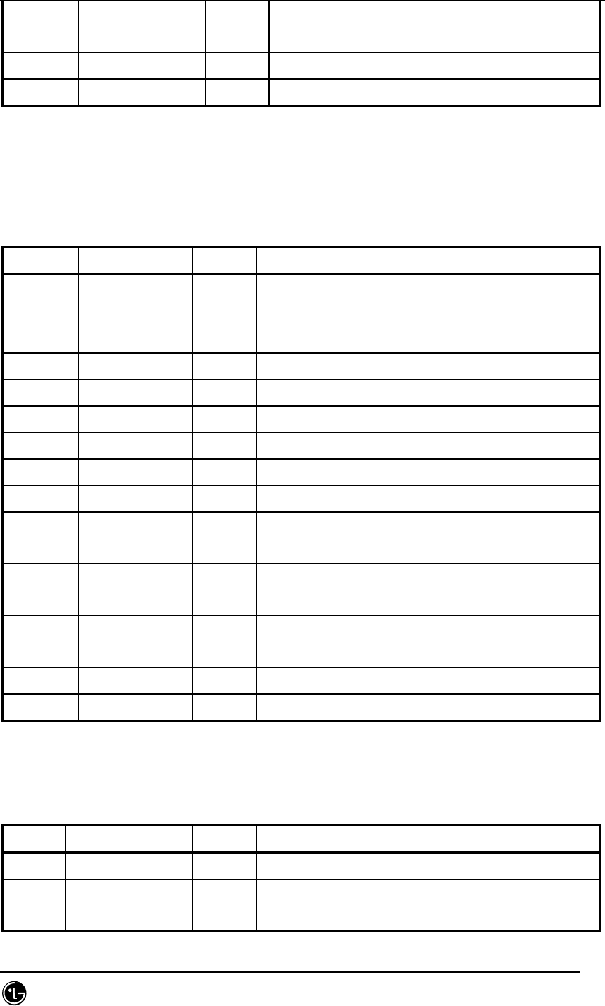
STAREX-IS BSM Manual
Page:830(877)
Issue:1.
0
SMD-011-PMA210
(Cell Bandwidth(~0x40) to be assigned to
Link)
word32 vpci_a[4096] Peer1 VPI/VCI (Ingress VPCI)
word32 vpci_b[4096] Peer2 VPI/VCI (Egress VPCI)
7.5.6.10. St_re_slb_pvc.dg
Table 7.5-48 St_re_slb_pvc
Type N a m e default Remarks
byte dummy key
word16 no_entry # of Valid Entries, defined PVC information
number (~512)
word16 reserved
byte equipage[512]
byte node_a[512] Peer1 connection ID (Ingress Node Conn. ID)
byte sub_a[512] Peer1 Logical Info
byte node_b[512] Peer2 Connection ID (Egress Node Conn. ID)
byte sub_b[512] Peer2 Logical info
byte no_vc[512] Number of VC to be used between Allocated VC
Number Peers
byte link_type[512] Link
LINK_AAL2(0), LINK_AAL5(1), LINK_TEST(2)
word16 link_bw[512] 0x100 VC Link Bandwidth
(Cell Bandwidth(~0x40) to be assigned to Link)
word32 vpci_a[512] Peer1 VPI/VCI (Ingress VPCI)
word32 vpci_b[512] Peer2 VPI/VCI (Egress VPCI)
7.5.6.11. St_re_vcb_pvc.dg
Table 7.5-49 St_re_vcb_pvc
Type N a m e default Remarks
byte dummy key
word16 no_entry # of Valid Entries, defined PVC information
number (~512)

STAREX-IS BSM Manual
Page:831(877)
Issue:1.
0
SMD-011-PMA210
word16 reserved
byte equipage[512]
byte node_a[512] Peer1 connection ID (Ingress Node Conn. ID)
byte sub_a[512] Peer1 Logical Info (measns final peer
connection)
byte node_b[512] Peer2 Connection ID (Egress Node Conn. ID)
byte sub_b[512] Peer2 Logical info
byte no_vc[512] Number of VC to be used between Allocated VC
Number Peers
byte link_type[512] Link
LINK_AAL2(0), LINK_AAL5(1), LINK_TEST(2)
word16 link_bw[512] 0x100 VC Link Bandwidth
(Cell Bandwidth(~0x40) to be assigned to Link)
word32 vpci_a[512] Peer1 VPI/VCI (Ingress VPCI)
word32 vpci_b[512] Peer2 VPI/VCI (Egress VPCI)
7.5.6.12. St_re_alb_pvc.dg
Table 7.5-50 St_re_alb_pvc
Type N a m e default Remarks
byte dummy key
word16 no_entry # of Valid Entries, defined PVC information
number (~512)
word16 reserved
byte equipage[512]
byte Node_a[512] Peer1 connection ID (Ingress Node Conn. ID)
byte sub_a[512] Peer1 Logical Info
byte Node_b[512] Peer2 Connection ID (Egress Node Conn. ID)
byte sub_b[512] Peer2 Logical info
byte no_vc[512] Number of VC to be ysed between Allocated VC
Number Peers
byte Link_type[512] Link
LINK_AAL2(0), LINK_AAL5(1), LINK_TEST(2)
word16 Link_bw[512] 0x100 VC Link Bandwidth
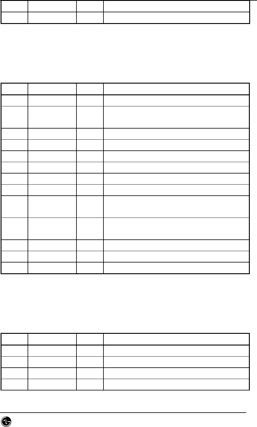
STAREX-IS BSM Manual
Page:832(877)
Issue:1.
0
SMD-011-PMA210
word32 vpci_a[512] Peer1 VPI/VCI (Ingress VPCI)
word32 vpci_b[512] Peer2 VPI/VCI (Egress VPCI)
7.5.6.13. St_re_loc_bs_pvc.dg
Table 7.5-51 St_re_loc_bs_pvc
Type N a m e default Remarks
byte dummy key
word16 no_entry # of Valid Entries, defined PVC information
number (~512)
word16 reserved
byte equipage[512]
byte node_a[512] Peer1 connection ID (Ingress Node Conn. ID)
byte sub_a[512] Peer1 Logical Info
byte node_b[512] Peer2 Connection ID (Egress Node Conn. ID)
byte sub_b[512] Peer2 Logical info
byte no_vc[512] Number of VC to be used between Allocated VC
Number Peers
byte link_type[512] Link
LINK_AAL2(0), LINK_AAL5(1), LINK_TEST(2)
word16 link_bw[512] 0x100 VC Link Bandwidth
word32 vpci_a[512] Peer1 VPI/VCI (Ingress VPCI)
word32 vpci_b[512] Peer2 VPI/VCI (Egress VPCI)
7.5.6.14. St_re_out_bs_pvc.dg
Table 7.5-52 St_re_out_bs_pvc
Type N a m e default Remarks
byte bs_id key full equip MAX_BS : 48
word16 no_entry # of Valid Entries (~512)
word16 reserved
byte equipage[512] According to bs equip, out_bs_pvc.inf

STAREX-IS BSM Manual
Page:833(877)
Issue:1.
0
SMD-011-PMA210
byte node_a[512] Peer1 connection ID (Ingress Node Conn. ID)
byte sub_a[512] Peer1 Logical Info
byte node_b[512] Peer2 Connection ID (Egress Node Conn. ID)
byte sub_b[512] Peer2 Logical info
byte no_vc[512] Number of VC to be used between Allocated VC
Number Peers
byte link_type[512] Link
LINK_AAL2(0), LINK_AAL5(1), LINK_TEST(2)
word16 link_bw[512] 0x100 VC Link Bandwidth
word32 vpci_a[512] Peer1 VPI/VCI (Ingress VPCI)
word32 vpci_b[512] Peer2 VPI/VCI (Egress VPCI)
7.5.6.15. St_re_atm_svc.dg
Table 7.5-53 St_re_atm_svc
Type N a m e defau
lt Remarks
byte Dummy key
word16 no_entry # of Valid Entries (~4096)
byte no_hdr Header Address Length (Upper ATM Address
Length)
byte reserved
byte addr_hdr[20] ATM Upper Address Id
byte equipage[512] Equip Flag
byte a_mask1[512][10] Peer1 Address Mask
byte addr1[512][10] Peer1 Address
byte a_mask2[512][10] Peer2 Address Mask
byte addr2[512][10] Peer2 Address
byte no_vc[512] Allocated VC Number
word32 atm_id1[512] Peer1 VC Ids’ List
word32 atm_id2[512] Peer2 VC Ids’ List
byte link_type[512] Link Usage
(LINK_AAL2(0), LINK_AAL5(1), LINK_TEST(2))
word16 link_bw[512] Cell Bandwidth(~0x40) to be assigned to VC
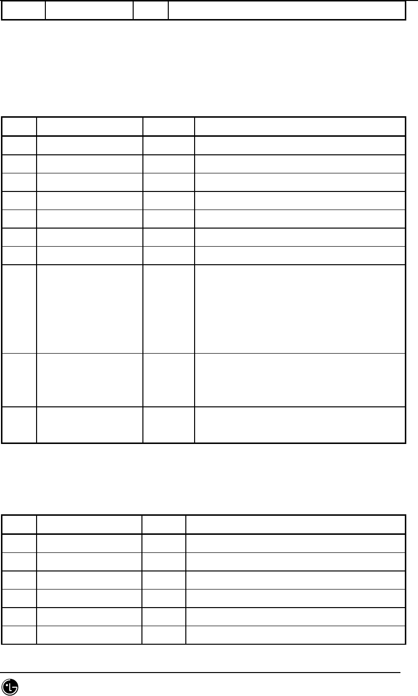
STAREX-IS BSM Manual
Page:834(877)
Issue:1.
0
SMD-011-PMA210
Link BandWidth(TBD,Link)
7.5.6.16. St_re_rnc_net_cfg.dg
Table 7.5-54 St_re_rnc_net_cfg
Type N a m e default Remarks
byte rnc_net_shelf_id key full equip (MAX_RNC_NET_SHELF: 2)
byte rnc_net_slot_id key full equip (MAX_RNC_SLOT: 22)
byte Equip ‘0’
byte bd_type Network Board Type
byte no_sub # of Sub Device
byte no_link # of Physical Link
byte hw_ctrl HW Reset : 0(Init), 1, 2, 3 added
byte link_type[MAX_LINK] 1 Physical Link Type : STM1,
E1,...(MAX_LINK: 64)
(LINK_TYPE_NONE(0),LINK_TYPE_STM1(1),
LINK_TYPE_STM12(2),LINK_TYPE_STM14(3),
LINK_TYPE_E1(4), LINK_TYPE_T1(5))
byte sub_type[MAX_SUB] Sub Device Type (MAX_SUB : 16)
(SBTYPE_NONE(0), SBTYPE_APC(1),
SBTYPE_APPD(2))
byte sub_id[MAX_SUB] Sub Device ID:Device Serial Number
(MAX_SUB : 16)
7.5.6.17. St_re_bs_net_cfg.dg
Table 7.5-55 St_re_bs_net_cfg
Type N a m e default Remarks
byte bs_id key full equip MAX_BS: 48
byte bs_net_slot_id key full equip (MAX_BS_SLOT: 22)
byte Equip ‘0’ Equip Flag
byte bd_type Network Board Type
byte no_sub # of Sub Device
byte no_link # of Physical Link

STAREX-IS BSM Manual
Page:835(877)
Issue:1.
0
SMD-011-PMA210
byte link_type[MAX_LINK] 1 Physical Link Type : STM1, E1,...(MAX_LINK:
64)
(LINK_TYPE_NONE(0),LINK_TYPE_STM1(1),
LINK_TYPE_STM12(2),LINK_TYPE_STM14(3),
LINK_TYPE_E1(4), LINK_TYPE_T1(5))
byte sub_type[MAX_SUB] Sub Device Type (MAX_SUB : 16)
(SBTYPE_NONE(0), SBTYPE_APC(1),
SBTYPE_APPD(2))
byte sub_id[MAX_SUB] Sub Device ID:Device Serial Number
(MAX_SUB : 16)
7.5.6.18. St_re_rnc_net_data.dg
Table 7.5-56 St_re_rnc_net_data
Type N a m e Default Remarks
byte dummy Key
byte msc_id msc_no Core Network ID
byte rnc_id bsc_no My RNC ID
byte can_equip can_eqp CAN Equipage
byte no_addr_hdr ATM Address Header Len
byte rnc_equip[MAX_RNC] rnc_eqp RNC Equipage (MAX_RNC : 12)
byte bs_equip[MAX_BS] bs_eqp BS Equipage (MAX_BS : 48)
byte smp_equip[MAX_SLBU] smp_eqp SLBU Equipage (MAX_SLBU : 5)
byte reserved[3]
word32 bs_svc_id[MAX_BS] BS SSCF-UNI Signalling VC ID (MAX_BS :
48)
byte atm_addr_hdr[20] ATM Address Header
byte cn_conn_type[2] 11 12 CN Connection ID
byte can_conn_type[2] 9 10 CAN Connection ID
In IS-2000 0 : CAN, 1 : CAN-D
In IMT-2000 0 : CAN0, 1 : CAN1
byte slb_conn_type[MAX_S
LBU]
16~20 SLBU Connection ID (MAX_SLBU : 5)
byte vcb_conn_type[MAX_V 21~28 VCBU Connection ID

STAREX-IS BSM Manual
Page:836(877)
Issue:1.
0
SMD-011-PMA210
CBU]
byte als_conn_type[4] 5~8 ALSU Connection ID
byte pip_conn_type[8] 29~36 PIP Connection ID
byte cmp_conn_type 15 CMP connection ID
byte reseved[6]
word32 ccp_addr CCP IP Address
word32 alp_addr ALP IP Address
word32 cnp_addr[2] CNP/CNP-D IP Address
0 : CNP Address, 1 : PNP Address
word32 smp_addr[MAX_SLBU] SMP IP address (MAX_SLBU : 5)
word32 asmu_addr[16] 2 ~ 17 ASMU Device Network Addr (for HDLC)
0: ASCA_A, 1: ASCA_B, 2: ASIA0_A, 3:
ASIA0_B,
4: ASIA1_A, 5: ASIA1_B, 6: ASIA2_A, 7:
ASIA2_B,
8: ASIA3_A, 9: ASIA3_B, 10: AOTA0, 11:
AOTA1,
12: AOTA2, 13: AOTA3, 14: ATSA0, 15:
ATSA1
7.5.6.19. St_re_rnc_iur_con.dg
Table 7.5-57 St_re_rnc_iur_con
‘Type N a m e default Remarks
byte Dummy key
word32 start_aal2_vc_id[MAX_RNC] *1 below AAL2 Start VC Id (MAX_RNC : 12)
word16 no_aal2_vc 32 Number of AAL2 VCs
word16 Reserved
‘
7.5.6.20. St_re_rnc_iub_con.dg
Table 7.5-58 St_re_rnc_iub_con
Type N a m e default Remarks
byte bs_id key MAX_BS : 48
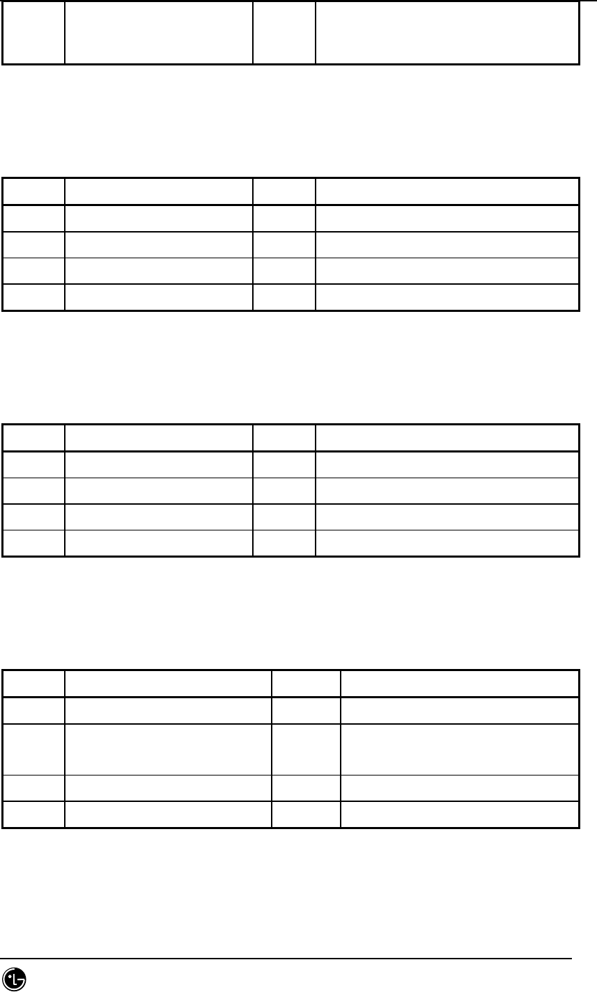
STAREX-IS BSM Manual
Page:837(877)
Issue:1.
0
SMD-011-PMA210
word32 aal2_vc_id
[MAX_LICA][MAX_LICA_LINK]
AAL2 Start VC Id.
MAX_LICA : 3, MAX_LICA_LINK : 16
7.5.6.21. St_re_rnc_slb_con.dg
Table 7.5-59 St_re_rnc_slb_con
Type N a m e default Remarks
byte Dummy key Applied to all SMPs in the same way
word32 start_aal5_vc_id[20] AAL5 Start VC Id 20VPs
word16 no_aal5_vc 1024 Number of AAL5 VCs 20VPs
word16 Reserved
7.5.6.22. St_re_rnc_vcb_con.dg
Table 7.5-60 St_re_rnc_vcb_con
Type N a m e default Remarks
byte Dummy key Applied to all VMPs in the same way
word32 start_aal5_vc_id[20] AAL5 Start VC Id 20VPs
word16 no_aal5_vc 128 Number of AAL5 VCs 20VPs
word16 reserved
7.5.6.23. St_re_rnc_alsu5_con.dg
Table 7.5-61 St_re_rnc_alsu5_con
Type N a m e default Remarks
byte Dummy key
word32 start_aal5_vc_id[MAX_ALMA][
MAX_ALPA][2]
AAL5 Start VC Id 20VPs
(MAX_ALMA : 2,MAX_ALPA : 5)
word16 no_aal5_vc 2048 Number of AAL5 VCs 20VPs
word16 Reserved
7.5.6.24. St_re_bs_net_data.dg
Table 7.5-62 St_re_bs_net_data
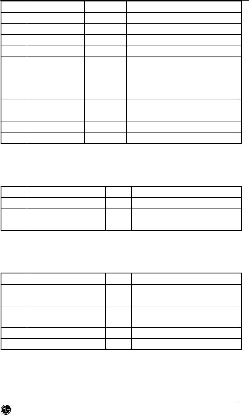
STAREX-IS BSM Manual
Page:838(877)
Issue:1.
0
SMD-011-PMA210
Type N a m e default Remarks
byte bs_id key full equip MAX_BS : 48
byte msc_id msc_no Core Network ID
byte rnc_id rnc_no My RNC ID
byte bs_id bs_no My BS ID
byte no_addr_hdr ATM Address Header Len
byte atm_addr_hdr[20] ATM Address Header
byte lica_conn_type[3] 146 147 148 LICA Connection ID
byte reserved
word32 svc_id [4/37] =
0x40025
BS SSCF-UNI Signalling VC
word32 crp_addr CRP IP Address
word32 banu_addr[5] BANU Device Network Addr
7.5.6.25. St_re_bs_iub_con.dg
Table 7.5-63 St_re_bs_iub_con
Type N a m e default Remarks
byte bs_id key MAX_BS: 48
word32 aal2_vc_id
[MAX_LICA][MAX_LICA_LINK]
AAL2 VC Id
MAX_LICA: 3 MAX_LICA_LINK:16
7.5.6.26. St_re_bs_rcu5_con.dg
Table 7.5-64 St_re_bs_rcu5_con
Type N a m e default Remarks
byte bs_id key full equip
MAX_BS: 48
word32 start_aal5_vc_id[MAX_RCU_
NODE][MAX_LICA]
AAL5 Start VC ID
(MAX_RCU_NODE : 10, MAX_LICA:3)
word16 no_aal5_vc[MAX_LICA] 512 Number of AAL5 VCs
word16 reserved
7.5.6.27. St_re_rnc_als_net_data.dg
Table 7.5-65 St_re_rnc_als_net_data
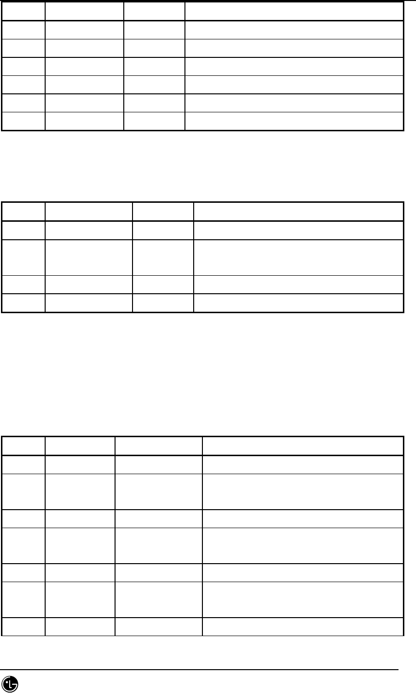
STAREX-IS BSM Manual
Page:839(877)
Issue:1.
0
SMD-011-PMA210
Type N a m e default Remarks
byte dummy key
byte msc_id msc_no MSC ID
byte rnc_id rnc_no RNC/BSC ID
byte reserved
word32 ncp_addr NCP Network Address
word32 alsu_addr[16] ALS Device Network Addr
7.5.6.28. St_re_rnc_cmp5_con.dg
Table 7.5-66 St_re_rnc_cmp5_con
Type N a m e default Remarks
byte dummy key
word32 start_aal5_vc_id [10/32] =
0xA0020
AAL5 Start VC Id.
word16 no_aal5_vc 1024 #of AAL5 VCs
word16 reserved
7.5.7. SCP ONLY
7.5.7.1. St_Lnit_dataSL.dg
Table 7.5-67 St_Lnit_dataSL
Type N a m e default Remarks
byte dummy
word16 act_cspu 1: CSPU_P(Primary) 2:
CSPU_S(Secondary)
int own_pc 3(bsc00) Local signaling point code
int adj_pc 0x050f : PCS
0x040f : DCN
Remote signaling point code
word16 tot_slk 4 Total number of Available Signal link
word16 link_st[16] 0~3 : 1
rest: 0
Signaling link status (0: unavailable
1:available)
word16 slc_no[16] 0 : slc_no[0] Signaling link code

STAREX-IS BSM Manual
Page:840(877)
Issue:1.
0
SMD-011-PMA210
1 : slc_no[1]
2 : slc_no[2]
3 : slc_no[3]
255 : rest
word16 vmp_no[16] 0 : vmp_no[0]
0 : vmp_no[1]
0 : vmp_no[2]
0 : vmp_no[3]
255 : rest
word16 trk_no[16] 16:trk_no[0]
48: trk_no[1]
80: trk_no[2]
112: trk_no[3]
0xffff: rest
Signal data link code
byte reserved_byt
e[35]
0
7.5.7.2. St_Lnit_dataST.dg
Table 7.5-68 St_Lnit_dataST
Type N a m e default Remarks
byte dummy
word16 tot_st 4 Total number of signal terminal
word16 st_st[16] 1: st_st[0~3]
2: st_st[4~15]
Signal terminal state ( 0: unavailable
1: available 2: Not Equip )
word16 sl_no[16] 0 : sl_no[0]
1 : sl_no[1]
2 : sl_no[2]
3 : sl_no[3]
255 : rest
Signal link number linked to signal
terminal
byte reserved_byt
e[34]
0
7.5.7.3. St_MLtwo_timer.dg
Table 7.5-69 St_MLtwo_timer

STAREX-IS BSM Manual
Page:841(877)
Issue:1.
0
SMD-011-PMA210
Type N a m e default Remarks
byte dummy 0 key
word16 T1 45000(msec) Timer “alignment ready”(40~50sec)
word32 T2 0xffff(msec) Timer “not aligned”(5~150sec)
word16 T3 1250(msec) Timer “aligned”(1-2sec)
word16 T4n 8000(msec) Normal proving period at 64
kbit/s(7.5~9.5sec)
word16 T4e 500(msec) Emergency proving period at
64kbit/s(400~600 msec)
word16 T5 100(msec) Timer “sendig SIB”(80~120 msec)
word16 T6 4500(msec) Timer “remote congestion”(3~5sec)
word16 T7 1250(msec) Timer “excessive delay of an
acknowledgement”(0.5~2sec)
byte reserved[20] 0
7.5.7.4. St_MLthree_timer.dg
Table 7.5-70 St_MLthree_timer
Type N a m e default Remarks
byte dummy 0 key
word16 T1 1000(msec) Delay time of 500-1200 msec to prevent message
mis-sequencing upon changeover
word16 T2 2000(msec) 700-2000 msec that waits changeover ack
word16 T3 1000(msec) 1. Although implemented in code, it is not
used.
2. delay time of 500-1200 msec to prevent
message mis-sequencing upon changeback by
MTP restart (Time controlled diversion
procedures)
word16 T4 1000(msec) Time of 500-1200 msec to wait changeback ack
word16 T5 1000(msec) 500-1200 msec to wait changeback ack
word16 T12 1000(msec) 800-1500 msec that waits uninhibit ack
word16 T13 1000(msec) 800-1500 msec that waits force uninhibit
word16 T14 2000(msec) 2000-3000 msec that waits inhibition ack
word16 T17 5000(msec) 800-5000 msec from Initial alignment failure

STAREX-IS BSM Manual
Page:842(877)
Issue:1.
0
SMD-011-PMA210
to next initial alignment command
word16 T22 240(sec) Local inhibit test timer3-6 minutes
word16 T23 240(sec) Remote inhibit test timer3-6 minutes
word16 SLTackT 5(sec) Time to wait for signal link test answer, with
range of 4sec~12sec
byte reserved[2
0]
0
7.5.7.5. St_SCCP_timer.dg
Table 7.5-71 St_SCCP_timer
Type N a m e default Remarks
byte dummy 0 key
word16 T_conne_est 20(sec) 1-2 minutes to wait connection confirm
word16 T_ias 300(sec) Delay time of 5-10 minutes used to conduct
inactivity test on connection section
word16 T_iar 660(sec) Waiting time of 11-21 minutes to receive
message on connection section
byte T_rel 10(sec) Waiting time of 10-20 sec to receive release
complete message
word16 T_int 10(sec) 1. although implemented in source, it is not
used.
2. upon connection release, it is the time to
freeze corresponding LRN for a certain time
to prevent the use of the same LRN
Extending to 1 minutes
word16 T_stat_info 30(sec) Interval that requests Subsystem status
information
Increasing value, 5-10 sec ~ 10-20 min
byte reserve[20] 0
7.5.8. CCP/BSP COMMON
7.5.8.1. St_bts_data_type.dg
Table 7.5-72 St_bts_data_type

STAREX-IS BSM Manual
Page:843(877)
Issue:1.
0
SMD-011-PMA210
Type N a m e default Remarks
byte bts_id full
byte EquipPage Equip dependent 0 : Not Equip 1 : Equip
word16 Sid 0x08ae As System Identification Number, 0 ~
32767(215 -1)
word16 Nid 15 As Netword Identification Number,
Network is system subset.
word16 base_id 0 Base Station Identification
Number(BTS’s own number)
byte bts_class
(base_class)
0(DCN)
1(PCS)
Base Station Class
Upon ‘0000’, Public Micorcelluar
System(800Mhz)
Upon ‘0001’, Public PCS System(1900Mhz
or 1800Mhz)
byte sys_type 0 : LGT PCS 1 : NW PCS
2 : JT PCS 3 : GIGA PCS
4 : CHINA PCS 5 : BRAZIL PCS
6 : WLL PCS 7 : RUSSIA PCS
byte bts_type 1 ~ 9 bts type identification (STANDARD: 1)
byte Sector_range 6 MAX Sector number of current system
word16 reg_zone 0 As Registration zone (SID+NID+ZONE_ID),
Network Subset.
byte pkt_zone 0 Zone ID for PCF Data call
Int32 ltm_off 18 Offset of local time from System time.
Offset of local time from UTC
current local time = SYS_TIME - LP_SEC
+ ltm_off
ltm_off = 18 ( 30 minutes per unit,
i.e., 9 hour difference)
* LP_SEC : Number of Leap seconds that
occurred since the start of System
Time.
boolean day_lt 0 Daylight saving time flag (Summer time)
1 : day lighting saving time
0 : standard time
word16 CDMA_FREQ 425 Primary CDMA Channel Number. – Sync Msg

STAREX-IS BSM Manual
Page:844(877)
Issue:1.
0
SMD-011-PMA210
word16 EXT_CDMA_FREQ 525 Upon use of RC3 or more or QPCH, see
this field.
byte Prat 0 paging channel data rate
byte no_ccp 0 equipage information of CCP
0 = equip , 1 = Not equip
int32 base_lat 0 BS latitude
int32 base_long 0 BS longitude
byte pilot_inc Pilot_PN_Offset value increases
byte turbo_encode_
flag
0 0 : Turbo Encoding not used
1 : Turbo Encoding used
byte reverse_pwr_f
lag
1 0 : Reverse Link Power Control not used
1 : Rerverse Link Power Contorl used
byte reserved_byte 0
7.5.8.2. St_sector_data_type.dg
Table 7.5-73 St_sector_data_type
Type N a m e defaul
t
Remarks
byte bts_id full BTS Identification
byte sector_id full Sector Identification
byte EquipPage 0 : Not Equip 1 : Equip
byte num_of_cdma_ch CDMA channel insertion number ( 1 ~ 8 )
word16 pilot_pn_offset offset of Pilot Pn from zero shifted PN
byte sector_cai_rev 6 CAI (Common Air Interface)
revision supported by base station
current BS S/W Version
1: IS95(Cellular),J-STD-008(PCS)
2: IS95A(Cellular)
3: TSB74(Cellular)
4,5: IS95B(Cellular,PCS)
6: IS-2000(Cellular,PCS)
byte sector_cai_min_rev 1 CAI Minumum revision supported by
base station
minimum version that BS can support to MS
byte call_control_para 0 Upon call congestion, by changing CAI
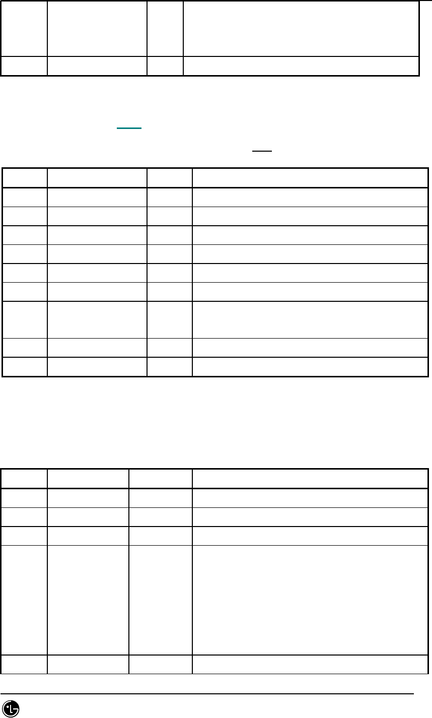
STAREX-IS BSM Manual
Page:845(877)
Issue:1.
0
SMD-011-PMA210
revision, it can increase the number of calls
that can be provided. Enable/disable flag of
corresponding function.
byte reserved_byte[32] 0
7.5.8.3. St_cdmach_data_type.dg
Table 7.5-74 St_cdmach_data_type
Type N a m e default Remarks
byte bts_id full BTS Identification
byte cdmach_id full CDMA Channel Identification
byte EquipPage 0 : Not Equip 1 : Equip
word16 freq_band 1800 Frequency Bandwidth
word16 cdmach_num number of cdmach channel
byte tce_reserved_4ho 20 Handoff preparatory traffic channel ratio ( %)
byte MAX_SCH_ALLOC_RATE 50 Parameter to determine the upper limit of
supplemental channel
byte reserve[2]
byte reserved_byte[34] 0
7.5.8.4. St_sys_param_msg_data_type.dg
Table 7.5-75 St_sys_param_msg_data_type
Type N a m e default Remarks
byte bts_id full BTS Identification
byte sector_id full Sector Identification
byte cdmach_id full CDMA Channel Identification
byte total_zones 2
Number of Registration Zones
As the number of location registration to be
held for use in Zone_based Registration, it
can be saved up to 7EA, and if components more
than it reside in ZONE_ LIST, MS removes the
oldest component.
byte zone_timer 2 When executing Zone-Based Registration, it

STAREX-IS BSM Manual
Page:846(877)
Issue:1.
0
SMD-011-PMA210
holds ZONE_LIST, and it is a field to
determine duration that an entry in ZONE_LIST
is removed from list.
That is, the loggest entry from ZONE_LIST is
the priority.
000(1 min),001(2 min),010(5 min),011(10 min),
100(20 min),101(30 min),110(45 min),111(60
min)
boolean home_reg 1
As Home registration ID, to enable auto
location registration, set this field to ‘1’,
and to disable that, set that to ‘0’.
Boolean mult_sids 0
multiple SID save indicator
If several elements that hold different SID in
SID_NID_LIST are saved, set that to ‘1’, and
in other case, set that to ‘0’. A maximum of
4EA can be saved.
Boolean mult_nids 0
multiple NID save indicator
If several elements that hold different NID in
SID_NID_LIST are saved, set that to ‘1’, and
in other case, set that to ‘0’.
byte max_sci 3
maximum slot cycle index
BS sets the length of allowed maximum slot
cycle to SLOT_CYCLE_INDEX.
The length of the slot cycle(T) = 2i
where i is the slot cycle index.
Slot mode operation : method to monitor only
1slot or 2slot assigned to corresponding MS
for one slot_cycle
boolean for_nid_reg 1 NID roamer location registration indicator
boolean for_sid_reg 1 SID roamer location registration indicator
boolean power_up_reg 1
Upon personal station registration, if it is
registered right before power ON, set that to
‘1’, and if not, set that to ‘0’.
boolean power_down_reg 1
Upon personal station registration, if it is
registered right before power OFF, set that to
‘1’, and if not, set that to ‘0’.

STAREX-IS BSM Manual
Page:847(877)
Issue:1.
0
SMD-011-PMA210
boolean parameter_reg 1 Parameter-change registration indicator
byte reg_prd 64
This is used for the calculation of MAX value
counted to execute Timer based registration,
and Timer based registration is executed when
counter reaches REG_COUNT_MAX, and
REG_COUNT_MAX is calculated as follows:
REG_COUNT_MAX = [ 2reg_prd/4 ]
word16 reg_dist 0
registration distance
0 : Personal Stations are not to perform
distance based registration.
Other than 0: Personal Stations are to perform
distance based registration.
ref : means 7.8m per unit.
byte srch_win_a 7 search window size for the active set
byte srch_win_n 9 search window size for the nghbr set
byte srch_win_r 10 search window size for the Remaining set
byte nghbr_max_age 1 Maximum age for retention of Neighbor set
member
byte pwr_rep_thresh 4
power control reporting threshold
As power control report threshold, set thi
snumber before MS measures TOT_FRAMES and
BAD_FRAMES and reports corresponding message
to BTS to transmit this value to BTS.
byte pwr_rep_frames 7(frames)
power control reporting frame count.
Num fwd tc frames for Total count
pwr_rep_frames = 2**(pwr_rep_frames/2) *5
boolean pwr_thresh_enab
le 0
Threshold report mode indicator
if (1) then pwr_rep_thresh = 00000
If MS frame error rate reaches to threshold,
it reports statistics.
if (0) then it prevents that from its
transmitting to MS.
Boolean pwr_period_enab
le 0
Periodic report mode indicator
if (0) then it prevents that from its sending
periodic power measuremtn msg to to MS.
if (1) then MS reports frame error rate at

STAREX-IS BSM Manual
Page:848(877)
Issue:1.
0
SMD-011-PMA210
certain intervals.
byte pwr_rep_delay 5
power report mode delay(min time between power
requests)
time from MS report to reattempt.
boolean rescan 0
After receiving this system parameter, for
reinitialization or system reobtaining, set
this fiel to ‘1’, and if not, set that to ‘0’.
byte t_add 26
As pilot detection threshold, this is used to
determine whether to transmit Pilot Strength
Measurement Messag. BTS sets this field as
pilot detection threshold.
byte t_drop 30
As pilot release threshold, this is used to
run Handoff release timer. BS sets this field
as pilot release threshold.
byte t_comp 5
As a comparative threshold, MS, if candidate
group pilot strength is lager than pilot
strength of active group by more than this
field, transmits Pilot Strength Measurement
Message.
byte t_tdrop 2
As release timer value, if pilot strength
falls below T_DROP, this is timer value until
certain activation. This is managed by MS and
managed regarding each pilot of active group
and candidate group.
byte ext_sys_paramet
er 1 Is there another sys_parameter?
byte ext_nghbr_list DCN: 0
PCS:1
BS sets this filed to ‘1’ to indicate
transmission of Extended Neighbor List
Message.
byte GEN_NGHBR_LIST 1 Field to check if BS uses General NGHBR_LIST
Msg through Paging Channel Message
byte global_redirect 0
Global Service Redirection Message indicator
BS, to transmit Global Redirection Message,
sets this field to 1, and if not, set that to
0.
At areas where both Amps and CDMA are used,

STAREX-IS BSM Manual
Page:849(877)
Issue:1.
0
SMD-011-PMA210
only one side should be used
( 0 : not changed
1 : change subject to message )
byte PRI_NGHBR_LIST Field for BS to check the status of Private
NGHBR_LIST Msg through Paging Channel Message
byte USER_ZONE_ID Field to check the status of User_zone_id Msg
through Paging Channel Message
byte EXT_GLOBAL_REDI
RECT
Field to check the status of
Ext_global_redirection Msg through Paging
Channel Message
byte EXT_CHAN_LIST 1 Field to check the status of Ext_channel_list
Msg through Paging Channel Message
byte reserved_byte[3
2] 0
7.5.8.5. St_ext_sys_param_msg_data_type.dg
Table 7.5-76 St_ext_sys_param_msg_data_type
Type N a m e default Remarks
byte bts_id full BTS Identification
byte sector_id full Sector Identification
byte cdmach_id full CDMA Channel Identification
byte pref_msid_type 3 Preferred Access Channel Personal Station
Identifier Type
010 : IMSI
011 : IMSI and ESN
110 : TMSI(valid TMSI is assigned)
IMSI(TMSI not assigned)
111 : TMSI(valid TMSI is assigned)
IMSI and ESN(TMSI not assigned)
Other value is reserved.
word16 mcc 349 Mobile Country Code
byte imsi_11_12 99 imsi : International Mobile Station Identity
imsi_11_12 is 11th, 12nd digits of imsi.
byte tmsi_zone_len 4 TMSI(Temporary Mobile Station Identity)
As temporary personal station identifier, it

STAREX-IS BSM Manual
Page:850(877)
Issue:1.
0
SMD-011-PMA210
consists of tmsi_zone and tmsi_code. BS sets
this field as the number of octet included in
tmsi_zone.
Byte tmsi_zone[8] 0 Length : 8*tmsi_zone_len
byte bcast_index 6 To enable periodic broadcast paging, BS sets
this field to ‘1~7’, and if not, set that to ‘0’.
byte IMSI_T_SUPPORT
ED
byte P_REV
(8bit)
6 Protocol revision level
BS sets this filed to ‘00000110’.
0 : 95
1 : JSTD-008 (PCS)
2 : 95A
3 : TSB74
4,5: 95B(based on completion ratio) – DCN, PCS
byte MIN_P_REV
(8bit)
1 Minimum protocol revision level.
Sets protocol revision level that BS can offer
to the minimum.
Band Class0 : 2 , Band Class1 : 1
byte SOFT_SLOPE
(6bit)
Included in the formaula used upon Add/Drop of
pilot to Active Set.
BS sets this filed as unsigned.
byte ADD_INTERCEPT
(6)
The intercept in the inequality criterion for
adding a pilot to the Active Set
BS sets this filed as complement of 3 in dB
unit.
byte DROP_INTERCEPT
(6)
The intercept in the inequality criterion for
dropping a pilot to the Active Set
BS sets this filed as complement of 3 in dB
unit.
byte MAX_NUM_ALT_SO
(3)
Maximum number of alternative service options.
BS makes MS set the number that includes
Origination Message or Page Response Message to
this field.
byte RESELECT_INCLU
DED
System reselection parameters included.
If BS includes system reselection parameters,

STAREX-IS BSM Manual
Page:851(877)
Issue:1.
0
SMD-011-PMA210
(1) set this field to ‘1’, and if not, set this field
to ‘0’.
byte EC_THRESH
(0 or 5)
Pilot power threshold.
If RESELECT_INCLUDED is set to ‘1’, BS includes
this field and sets that as follows:
(pilot_power_threshold + 115)
pilot_power_threshold measns
pilot power(Ec), and MS performs system
reselection if the output of corresponding pilot
is below this filed.
byte EC_IO_THRESH
(0 or 5)
Pilot Ec/Ic threshold.
If RESELECT_INCLUDED is set to ‘1’, BS includes
this filed and sets that as follows:
-20 * log10(pilot threshold)
pilot threshold means pilot Ec/Io. MS, if
Ec/Io is below this field, executes system
reselection.
byte PILOT_REPORT
(1)
Pilot reporting indicator.
If this field is set to ‘1’, MS reports
corresponding pilot information.
If it is set to ‘0’, it only reports that to
Originationmessage and Page Responsemesage.
byte NGHBR_SET_ENTR
Y_IN
FO (1)
Neighbor Set access entry handoff information
included indicator.
If BS includes Neighbor Set access entry handoff
information, set this field to ‘1’, and if not,
set that to ‘0’.
byte ACC_ENT_HO_ORD
ER
(0 or 1)
Access entry handoff permitted indicator.
If NGHBR_SET_ENTRY_INFO field is ‘0’, omit this
field, and if ‘1’, it allows MS access entry
handoff while MS, In idle state, executes
Mobile Station Order and Message Processing
Operation.
byte NGHBR_SET_ACCE
SS_INFO (1)
Neighbor Set access handoff included indicator.
If BS includes Neighbor Set access handoff or
access probe handoffinfo, set this field to ‘1’,

STAREX-IS BSM Manual
Page:852(877)
Issue:1.
0
SMD-011-PMA210
and if not, set this field to ‘0’.
byte ACCESS_HO
(0 or 1)
Access handoff permitted indicator.
If NGHBR_SET_ACCESS_INFO is ‘0’, omit this field,
and if ‘1’, it allows MS access handoff. It sets
this filed to ‘1’, and if not, it sets that to
‘0’.
byte ACCESS_HO_MSG_
RSP
(0 or 1)
Access handoff permitted for message response
indicator. If ACCESS_HO is ‘0’, omit this field,
and if ‘1’, it sets this field to 1 and if not it
sets this field to 0.
byte ACC_PROBE_HO
(0 or 1)
Access probe handoff permitted indicator.
If NGHBR_SET_ACCESS_INFO is ‘0’, omit this field,
and if ‘1’ and it allows MS access probe handoff,
it sets this field to ‘1’, and if not, set that
to ‘0’.
byte ACC_HO_LIST_UP
D
(0 or 1)
Access handoff list update permitted indicator.
If ACCESS_PROBE_HO is ‘0’, omit this field, and
if ‘1’, and it allows update of access handoff
list, it sets this field to ‘1’, and if not, it
sets that to ‘0’.
byte ACC_PROBE_HO_O
THER_MSG (0 or
1)
Access probe handoff permitted for messages
other than the Origination Message and the Page
Response Message.
If ACCESS_PROBE_HO is ‘0’, it omits this field,
and if ‘1’, and it allows access probe handoff,
it sets this field to ‘1’, and if it allows that
only to Origination Message and Page Response
Message, set this field to ‘0’.
byte MAX_NUM_PROBE_
HO
(0 or 3)
Maximum number of times that the mobile station
is permitted to perform an access probe handoff.
If ACCESS_PROBE_HO is ‘0’, omit this field, and
if ‘1’, set the maximum number so that MS
executes access probe handoff.
byte BROADCAST_GPS_
ASST
(1)
Broadcast GPS Assist Indicator.
If BS supports Broadcast GPS Assist, set this
field to ‘1’, or not, set that to ‘0’.

STAREX-IS BSM Manual
Page:853(877)
Issue:1.
0
SMD-011-PMA210
byte QPCH_SUPPORTED
(1)
1 Quick Paging Channel Supported Indication.
If BS supports Quick Paging Channel operation,
set this field to ‘1’, or not, set that to ‘0’.
byte NUM_QPCH
(0 or 2)
1 Number of Quick Paging Channels.
If QPCH_SUPPORTED is ‘0’, omit this field, and
if ‘1’, BS sets this field as many as the number
of Quick Paging Channel over CDMA Channel. BS
will not set this field to ‘0’.
byte qpch_rate 0 data rate over radio section
Range : 0~1(0:9600bps, 1:4800bsp)
Same as data_rate of qpch_data
byte QPCH_POWER_LEV
EL_PAGE
(0 or 3)
Quick Paging Channel paging indicator
transmit power level.
If QPCH_SUPPORTED is ‘0’, it omits this field,
and if ‘1’, BS sets this field in accordance with
Table 3.7.2.3..2.13-3.
byte QPCH_CCI_SUPPO
RTED
(0 or 1)
Quick Paging Channel configuration change
indicator supported
If QPCH_SUPPORTED is ‘0’, omit this field, and if
‘1’, and BS supports configuration change
indicators, it sets this field to ‘1’, or not it
sets this field to ‘0’.
byte QPCH_POWER_LEV
EL_CONFIG
(0 or 3)
Quick Paging Channel configuration Change
indicator trasmit power level.
If QPCH_CCI_SUPPORTED is ‘0’, it omits this
field, and if ‘1’, it sets this field in
accordance with Table 3.7.2.3.2.13-3.
byte SDB_SUPPORTED
(1)
Short Data Burst supported indicator.
If MS can send Short Data Burst, BS sets this
field to ‘1’, or not sets that to ‘0’.
byte MAC_CF_SUPPORT
ED
(1)
MAC (Medium Access Control) control function
supported indicator.
If BS supports MAC control functions, BS sets
this field to ‘1’, or not, it sets that to ‘0’.
byte RLGAIN_TRAFFIC
_PILOT
Gain adjustment of the Reverse Traffic Channel
relative to the Reverse Pilot Channel for Radio

STAREX-IS BSM Manual
Page:854(877)
Issue:1.
0
SMD-011-PMA210
(6) Configurations greater than 2.
BS sets this field with reverse traffic channel
power value.
byte reserved_byte[
33]
0
7.5.8.6. St_nghbr_list_msg_data_type.dg
Table 7.5-77 St_nghbr_list_msg_data_type
Type Name Default Remarks
byte bts_id full BTS Identification
byte sector_id full Sector Identification
byte nghbrs_in_msg nghbr_list number held by one sector
byte nghbr_srch_mode Parameter included in GNLM
byte use_timing If Nghbr Base station transmits pilot in DTX
mode, it indicates the use of timming
information.
byte global_timing_inc
l
When use_timing is set to ‘1’, this indicates
whether all neighbors use the same timing
information.
byte global_tx_duratio
n
As Pilot Transmission duration of Neighbor Base
Station, it is valid only if all neighbors use
the same value.
byte global_tx_period Valid only if all neighbors use the same value
with DTX cycle of Pilot Transmission of Neighbor
Base Station.
byte srch_offset_incl
byte nghbr_config[ ] When the value of this field is as follows:
000 : upon handoff The personal station shall
begin monitering the Paging Channel of the new
base station, using the same Code Channel.
001 : The personal station shall begin
monitergin the primary paging channel of the new
base station.
010 : The nghbr base station has a different
number of frequencies having Paging Channels as

STAREX-IS BSM Manual
Page:855(877)
Issue:1.
0
SMD-011-PMA210
the current station.
word16 nghbr_pn[ ] pilot_pn_offset pf sector
word16 nghbr_sid[ ] system identification value of BS to which a
sector belongs
word16 nghbr_nid[ ] Network identification value of BS to which
corresponding sector belongs
word16 nghbr_base_id[ ] base_id value of neighbor BS
byte nghbr_msc_id[] msc_id value
byte nghbr_bsc_id[] bsc_id value
byte nghbr_bts_id[ ] bts_id value
Byte nghbr_sect_id[ ] Sector id value
byte nghbr_msc_type[] 0 0 : local MSC
1 : remote MSC
Necessary to determine Soft, Hard H/O upon H/O.
For local MSC, Soft H/O is possible, and for
remote MSC, Hard H/O is attempted.
byte nghbr_bsc_type[] 0 0 : local BSC
1 : remote BSC
Necessary to determine Soft, Hard H/O upon H/O.
For local MSC, Soft H/O is possible, and for
remote MSC, Hard H/O is attempted.
byte nghbr_beacon_pn[] 0 indicator
byte search_priority[] the search priority for the Pilot Channel
corresponding to NGHBR_PN.
Value Search Priority Value Search Priority
00 Low 01 Medium
02 High 11 Very high
byte freq_incl[] Frequence included indicator. That is, if this
field is 1, upon handiff, it uses channels on
nghbr_band and nghbr_freq and if 0 , it uses
current channel as is.
byte nghbr_band[]
If freq_incl field is set to ‘1’
band class of candidate frequency
800Mhz: 0
1800Mhz : 4 = domestic
1900Mhz: 1 = overseas

STAREX-IS BSM Manual
Page:856(877)
Issue:1.
0
SMD-011-PMA210
word16 nghbr_freq[] If freq_incl field is set to ‘1’
this field to the CDMA channel Number
freq_incl field is set to ‘0’ disregarded
byte timing_incl[] B : MS moves at 2FA -> 5FA
B is the value on 3,4,5FA. It is held by 5FA
BS.
If each Nghbr Sector transmits pilot in DTX
mode, it indicates timing information.
byte nghbr_tx_offset[] Transmission start offset value of each nghbr
sector
byte nghbr_tx_duration
[]
Pilot Transmission time value of each Nghbr
Sector
byte nghbr_tx_period[] Pilot DTX cycle value of each Nghbr Sector.
byte srch_set[] To indicate the status of each Nghbr Pilot.
byte add_pilot_rec_inc
l []
Indicates the status of additinal record
regarding each Nghbr Pilot.
byte nghbr_pilot_rec_t
ype []
Additional Record Type(Information Type)
Identification of each Nghbr Pilot
byte td_pilot_otd_pwr[
]
OTD Transmit Power Level of each Nghbr Pilot
byte srch_offset_nghbr
[]
Search Window offset value regarding each
Neighbor Pilot
byte access_entry_ho[
]
Should be repeated as many as NGHBR_SET_SIZE.
Access entry handoff permitted when entering
the System Access State.
If before MS receives message through Paging
Channel in idle state, and for response, it
transits to System Access State, BS sets this
field to 1 or not it sets that to 0 if access
entry handoff is allowed.
The order of ACCESS_ENTRY_HO is the same as
that of Neighbor List Message, Extended
Neighbor List Message or General Neighbor List
Message.
byte access_ho_allowe
d[]
Should be repeated as many as NGHBR_SET_SIZE.
Access handoff and access probe handoff
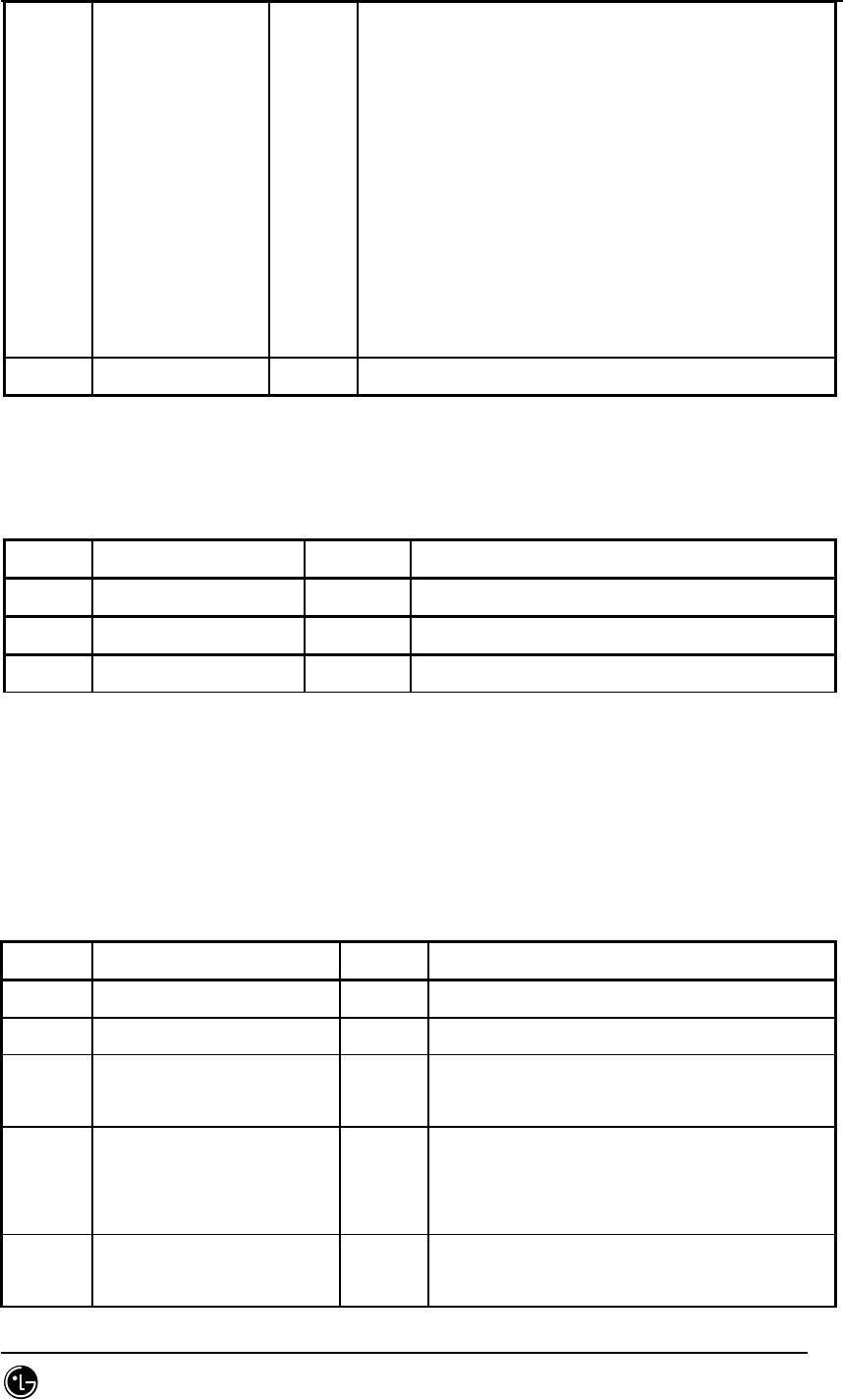
STAREX-IS BSM Manual
Page:857(877)
Issue:1.
0
SMD-011-PMA210
permitted for the corresponding pilot while in
the System Access State.
If MS is in System Access State, BS sets this
field to 1 or not it sets that to 0 if MS
access handoff or access probe handoff is
allowed.
The order of ACCESS_HO_ALLOWED is the same as
that of Neighbor List Message, Extended
Neighbor List Message or General Neighbor List
Message.
byte reserved_byte[34] 0
7.5.8.7. St_Qos_param_data
Table 7.5-78 St_Qos_param_data
Type N a m e default Remarks
byte bts_id full
byte max_sch_rate
byte reserved_byte[106] 72 + 34
7.5.9. BSP Layer
7.5.9.1. St_pwr_mgt_param_type.dg
Table 7.5-79 St_pwr_mgt_param_type
Type N a m e default Remarks
byte sector_id full Sector Identification (0 ~ 2)
byte cdmach_id full CDMA Channel Identification(0 ~ 7)
byte T_rx_filter 0 Received total power filter update rate.
Ms units, 1/2 step, 20/2 ~ 255 range
byte G_rx_filter 0 Received total power filter delay
contant.
1/256 step. 0/256 ~ 255/256 range
byte G_tx_filter 0 Transmit power filter delay constant
1/256 step. 0/256 ~ 255/256 range

STAREX-IS BSM Manual
Page:858(877)
Issue:1.
0
SMD-011-PMA210
byte Gh_tx_filter 0 Pilot Channel gain
int16 R_tx_pilot 0 Minimum trasmit pilot power to transmit
total power ratio for sector j.
1/16 step, -255/16 ~ 0/16
byte flnk_call_blk_thresh 0 call blocking threshold. Nuit : %
byte flnk_handoff_blk_thresh 0 Handoff blocking threshold. Unit : %
byte flnk_gain_scaling_thresh 0 traffic gain scaling threshold
byte rlnk_call_blk_thresh 0 call blocking threshold
byte rlnk_handoff_blk_thresh 0 handoff blocking threshold
byte A_tx_max 0 Maximum transmit gain
byte delta_A_tx 0 Maximum transmit gain rate of chagne
1/16 step. 1/16 ~ 255/16 range
byte K_level 0 Breathing equation level
byte K_slope 0 Breathing equation level
1/128 step, 1/128 ~ 128/128 range
byte K_delta 0 Breathing equation level
1/16 step, 0/16 ~ 255/16 range
byte delta_T 0 General update rate, ms unit
byte P_tx_max 0 Maximum transmit total power. DBmW unit
byte initial_calib 1 0: Overhead_ch Calibration Enabled
1: Blossoming Enabled
byte periodic_calb 1 0: Overhead_ch Calibration Enabled
1: TPTL Calibration Enabled
byte breathing_flag 0 0: Breathing Disable
1: Breathing Enable
byte pwr_est_flag 0 0: Forward/Reverse Link Power estimation
Enabled
1: Forward/Reverse Link Power estimation
Disabled
byte overpwr_limit 1 0: HPA Over Power Limitation Disabled
1: HPA Over Power Limitation Enabled
byte flnk_cap_limit 0 0: Forward Link Excess Capacity
Limitation
Disabled
1: Forward Link Excess Capacity
Limitation

STAREX-IS BSM Manual
Page:859(877)
Issue:1.
0
SMD-011-PMA210
Enabled
byte rlnk_cap_limit 0 0: Reverse Link Excess Capacity
Limitation
Enabled
1: Reverse Link Excess Capacity
Limitation
Disabled
byte reserved_byte[33] 0
7.5.9.2. St_txms_param_data.dg
Table 7.5-80 St_txms_param_data
Type N a m e default Remarks
byte sector_id full Sector Identification
byte cdmach_id full CDMA Channel Identification
word16 ovhdch_erp 170(1.7W) Overhead Channel Effectiver Radiation Power
and 170 means 1.7W(32dBm).
word16 delta_erp No-use ERP calibration value
word16 delta_sign No-use Calibration value symbol (0: PLUS, 1:MINUS)
byte reserved_byte[32] 0
7.5.9.3. St_tic_data_type.dg
Table 7.5-81 St_tic_data_type
Type N a m e default Remarks
byte sector_id full Sector Identification
byte cdmach_id full CDMA Channel Identification
byte primary_function 1
word16 tx_gain 0x900(2304) Overall sector transmit gain setting
byte rx_a_atten No-use 255 Noise attenuator setting for the receiver
A paths in 0.5 dB steps(0~63.5dB)
byte rx_b_atten No-use 255 Noise attenuator setting for the receiver
B paths in 0.5dB steps(0~63.5dB)

STAREX-IS BSM Manual
Page:860(877)
Issue:1.
0
SMD-011-PMA210
byte tx_atten No-use 255 Noise attenuator setting for the transmit
paths in 0.5 dB steps(0~63.5dB)
boolean breathing No-use 0 Whether cell power “breathing” enabled.
byte expected_db No-use 16 Cell breathing threshold in db.
word16 power_upper_bound No-use 20 TICrecerse power threshold upper bound
word16 power_lower_bound No-use 15 TICrecerse power threshold upper bound
byte reserved_byte[33] 0
7.5.9.4. St_acc_param_data_type.dg
Table 7.5-82 St_acc_param_data_type
Type N a m e default Remarks
byte sector_id full Sector Identification(0 ~ 2)
byte cdmach_id full CDMA Channel Identification(0 ~ 7)
byte pc_id full Paging Channel Identification(0 ~ 7)
byte nom_pwr 0 Power control value for Open loop Power Control
byte init_pwr 0 Initial power offset for access
Power control value for Open Loop Power Control
for MS Access Channelinitial transmission
byte pwr_step 3 Power increment
Power amount value increased by MS between
continuous probes at Access Probe Sequence
byte num_step 6 Number of access probe
As the number of Access Probe, this is the value
that is smaller by 1 than maximum access probe
number transmitted from one Access Probe
Sequence.
byte max_cap_sz 3 Max Access Channel message capsule size
As value that indicates maximum access channel
message capsule size, BS sets this field to
value that is smaller by 3 than access channel
frame number.
byte pam_sz 3 Access Channel preamble length
As the length of access channel preamble, BS
sets value that is smaller by 1 than access

STAREX-IS BSM Manual
Page:861(877)
Issue:1.
0
SMD-011-PMA210
channel frame number transmitted from access 채
channel preamble.
byte psist_0_9 0 As value on access overload grade(0~9), if
access pverload grade allows 0~9 MS to transmit
request to access channel, BS sets that as
continuous value to use this field and if not,
it sets that to ‘111111’.
byte psist_10 0 If test MS with access overlaod grade of 10 is
allowed to transmit requests to access channel,
BTS sets that as continuous value to use this
field, and if not, it sets that to ‘111’.
byte psist_11 0 If emergency MS with access overlaod grade of 11
is allowed to transmit requests to access
channel, BTS sets that as continuous value to
use this field, and if not, it sets that to
‘111’.
byte psist_12 0 If MS with access overlaod grade of 12 is
allowed to transmit requests to access channel,
BTS sets that as continuous value to use this
field, and if not, it sets that to ‘111’.
byte psist_13 0 If MS with access overlaod grade of 13 is
allowed to transmit requests to access channel,
BTS sets that as continuous value to use this
field, and if not, it sets that to ‘111’.
byte psist_14 0 If MS with access overlaod grade of 14 is
allowed to transmit requests to access channel,
BTS sets that as continuous value to use this
field, and if not, it sets that to ‘111’.
byte psist_15 0 If MS with access overlaod grade of 15 is
allowed to transmit requests to access channel,
BTS sets that as continuous value to use this
field, and if not, it sets that to ‘111’.
byte msg_psist 0 As continuous transformer used to attempt
accesschannel for message transfer, MS
multiples [2-MSG_PSIST] to transmission
probability.

STAREX-IS BSM Manual
Page:862(877)
Issue:1.
0
SMD-011-PMA210
byte reg_psist 0 MS multiplies [2-MSG_PSIST] to transmission
probability.
byte probe_pn_ran 0 As a field related to time random for access
channel probe, BS sets value of 0~9 so that the
range of time random value is 2PROBE_PN_RAN-1
chip.
byte acc_tmo 6 Answer time excessive value.
byte probe_bkoff 0 Backoffrange of accesws channel probe
byte bkoff 1 As access channel probe sequence backoff range,
BS sets this field with the value that is lower
by 1 than the number of slots that are delayed
owing to backoff.
byte max_req_seq 2 BS should set that with value greater than 0.
byte max_rsp_seq 2 BS should set that with value greater than 0.
byte auth 0 If MS includes standard authentication data
inaccess channel nmessage, BTS sets this field
to ‘01’, and if not it sets that to ‘00’.
word32 rand 0 If auth field value is ‘01’, BTS sets this field
to random attempt value to be used upon
authentication and if different value, it is
omitted.
byte nom_pwr_ext 0(DCN)
1(PCS)
extended nominal transmit power open loop power
stimate: -24dB ~ -9dB if this field is ‘1’, -
8dB ~ 7dB if this field is ‘0’
byte reserved_byte[35] 0
7.5.9.5. St_pc_global_redirect_msg_type.dg
Table 7.5-83 St_pc_global_redirect_msg_type
Type N a m e default Remarks
byte sector_id full Sector Identification
word16 redirect_accolc 65535 redirect ACCess OverLoad Class indicator
byte return_if_fail 1 1: If personal system fails to redirect to
other system, it allows entry to original

STAREX-IS BSM Manual
Page:863(877)
Issue:1.
0
SMD-011-PMA210
system.
0 : No return
byte delete_tmsi 0 Delete TMSI Indicator
byte EXCL_P_REV_MS Indicator to apply Global Service
redirection Message(GSRM) to MOB_P_REV 6 or
above.
byte REDIRECT_P_REV_INCL Indicator to divide the application scope
of EGSRM according to MOB_P_REV value.
byte
EXCL_P_REV_INCL Indicator to exclude the application of
GSRM regarding MS that has corresponding
MOB_P_REV.
byte REDIRECT_P_MIN 6 MOB_P_REV Minimum value of MS that will
apply and exclude GSRM
byte REDIRECT_P_MAX 6 MOB_P_REV Maximum value of MS that will
apply and exclude GSRM
byte record_type 2 00000001: Redirection to an analogue
system as defined in IS95
00000010: Redirection to an CDMA system
as defined in IS95
byte record_len 3 The base station shall set this field to the
number of octets in the type-specific fields
of this redirection record.
Word16 expected_a_sid 0 If Base station has personal station
redirected to specific system, insert sid#
of specific system.
0 : no use of specific system
byte ignore_cdma 1 1: when personal station is redirected to
analog system, CDMA Capability Msg is
disregarded.
0: if personal station receives CDMA
Capability Msg, it may not receive service
from redirected system.
Byte sys_ordering 3 Determines where to redirect (see STD-008 p
3-175)
byte band_class 0(DCN)
1(1900Mg
If record_type is ‘00000010’ for
redirection, Band class of redirected

STAREX-IS BSM Manual
Page:864(877)
Issue:1.
0
SMD-011-PMA210
z)
4(1800Mh
z)
system should be filled.
800Mhz: 0
1800Mhz : 4 = domestic
1900Mhz: 1 = overseas
Word16 expected_sid 0 If Base station has personal system
redirected to other system, this sets this
field to SID of redirected system.
Word16 expected_nid 0 If Base station has personal system
redirected to other system, this sets this
field to NID of redirected system.
Byte num_chans 0 The number of occurence of cdma_chan FIELD
word16 cdma_chan[10] 0 For each CDMA Channel on which the personal
station is to attempt to acquire a CDMA
system, the base station shall include one
occurrence of this field specifying the
associated CDMA Channel number.
byte reserved_byte[34] 0
7.5.9.6. St_bts_cfg_type
Table 7.5-84 St_bts_cfg_type
Type N a m e default Remarks
byte dummy_key full
BYTE OVHD_MODE 0 0: Dynamic 1: Fix
byte pa_type 2 RF type
0: PA_NEQ 1: HPA
2: LPA(MPD) 3:LPA(MILCOM)
byte ant_type 0 ~ 3 0 : Standard 1 : OTA
2 : DAI 3 : DAI_OAI
BYTE TX_DIVERSITY 0 ~ 1 0: Not Tx Diversity 1: Tx Diversity
byte rx_duplex 0 ~ 1 0: Simplex_antenna 1: Duplex_antenna
byte rx_diversity 0 ~ 1
current
‘1’
0: Non_Diversity 1: Diversity
rx_diversity:0, St_chip_config_data
diversity_scale_2000:0
byte lna_type 0 : Not_Equip 1 : Equip

STAREX-IS BSM Manual
Page:865(877)
Issue:1.
0
SMD-011-PMA210
When MIC C, D are used for subway, this file
is set to ‘0’.
byte ttrf_type[12] 0 0 : Not_Equip, 1 : Equip,
2 : Equip and Blocked.
4EA per sector among 12EA.
byte fa_use 0: 1FA-6Sec 1; 2FA-3Sec
byte risa_eqp 1 0: not equip, 1: equip
byte reserved_byte[34] 0 Reserved Field
7.5.9.7. St_dru_chc_data_type
Table 7.5-85 St_dru_chc_data_type
Type N a m e default Remarks
byte proc_id full 0~9 Processor Identification
byte EquipPage 0:Not Equip 1:Equip
BYTE CHC_STATE[MAX_CHC] Not_equip/Block/Unblock
BYTE CHIP_STATE[MAX_CHC][MAX_CHI
P]
0 Chip status per channel card
Not_equip/Block/Unblock
byte reserved_byte[33] 0
7.5.9.8. St_chip_config_data
Table 7.5-86 St_chip_config_data
Type N a m e default Remarks
byte DUMMY full 0
byte num_chip_per_chc 2
word16 sector_gain[MAX_SECTORS] 208 sector gain(Normal Path)
Range : 0~4095
word16 tx_div_sector_gain[MAX_SECTORS] 0 sector gain(Tx Diversity
Path)
Range : 0~4095
word16 sector_timing_adv[MAX_SECTORS] 320 Timing advance (Normal
Path)
Max : 1264

STAREX-IS BSM Manual
Page:866(877)
Issue:1.
0
SMD-011-PMA210
word16 tx_div_timing_adv[MAX_SECTORS] 0 Timing advance (Tx
Diversity Path)
Max : 1264
byte sector_tx_io_format 0 (6 path or
below)
2 (3 path or
below)
0:tx_output_chipx1, 1:
tx_output_chipx1_fir
2: tx_output_chipx2_fir
word16 cell_radius 511 in units of PN chip
byte rev_input_format 1 (6 path or
below)
0 (3 path or
below)
0:chipx8_rate_input, 1:
chipx2_rate_input
byte ant_enable[MAX_ANTENNAS] MAX_ANTENNAS = 12
byte ant_source[MAX_ANTENNAS] ?
byte rev_cell_mode ?
byte max_rach_fraction 10 MAX=32
word32 max_rach_separation 80 MAX=512
byte max_reach_fraction 10 MAX=32
word32 Max_reach_separation 80 MAX=512
byte enable_srch_win_adj 1
byte max_finger_per_chan95 6 MAX=6
byte max_finger_per_chan2000 8 MAX=8
byte usefully_rate_likely No-use 1
byte finger_thresh_adj_enable No-use ?
byte channel_finger_limit No-use ?
byte csm_mode 1 0:non_backward_compatible,
1: backward_compatible
byte diversity_scale_2000 3 Range : 0~3
int min_search_energy_rach No-use 150
int min_search_energy_rc1 No-use 200
int min_search_energy_rc2 No-use 200
int min_search_energy_rc3 No-use 40
int min_search_energy_rc4 No-use 40
int min_search_energy_rc5 No-use
int min_search_energy_rc6 No-use
int override_search_energy_rach No-use

STAREX-IS BSM Manual
Page:867(877)
Issue:1.
0
SMD-011-PMA210
int override_search_energy_rc1 No-use
int override_search_energy_rc2 No-use
int override_search_energy_rc3 No-use
int override_search_energy_rc4 No-use
int override_search_energy_rc5 No-use
int override_search_energy_rc6 No-use
word16 turbo_dtx_threshold No-use 240
word16 conv_dtx_threshold No-use 392
byte bin_size No-use
byte integration_period No-use
word16 srch_win_len[MAX_SECTORS] 1(traffic) Range : 1~32
byte reserved_byte[32] 0
7.5.9.9. St_hpbch_data
Table 7.5-87 St_hpbch_data
Type N a m e default Remarks
BYTE SECTOR_ID 0 ~ 2
BYTE PILOT_GAIN pilot channel gain
BYTE NUM_CDMA_CH number of cdma channel of hopping
beacon
WORD16 CDMA_FREQ[MAX_CDMACH] CDMA Channel Number for Hopping Beacon.
BYTE BEACON_TX_OFFSET[MAX_CDM
ACH]
Pilot beacon transmit time offset .
Reading the value from
Neighbor_list_msg_data.dg for setting.
BYTE BEACON_TX_DURATION[MAX_C
DMACH]
Pilot beacon transmit time duration .
Reading the value from
Neighbor_list_msg_data.dg and setting.
BYTE BEACON_TX_PERIOD[MAX_CDM
ACH]
Pilot beacon transmit time .
Reading the value from
Neighbor_list_msg_data.dg and setting.
byte reserved_byte[32] 0
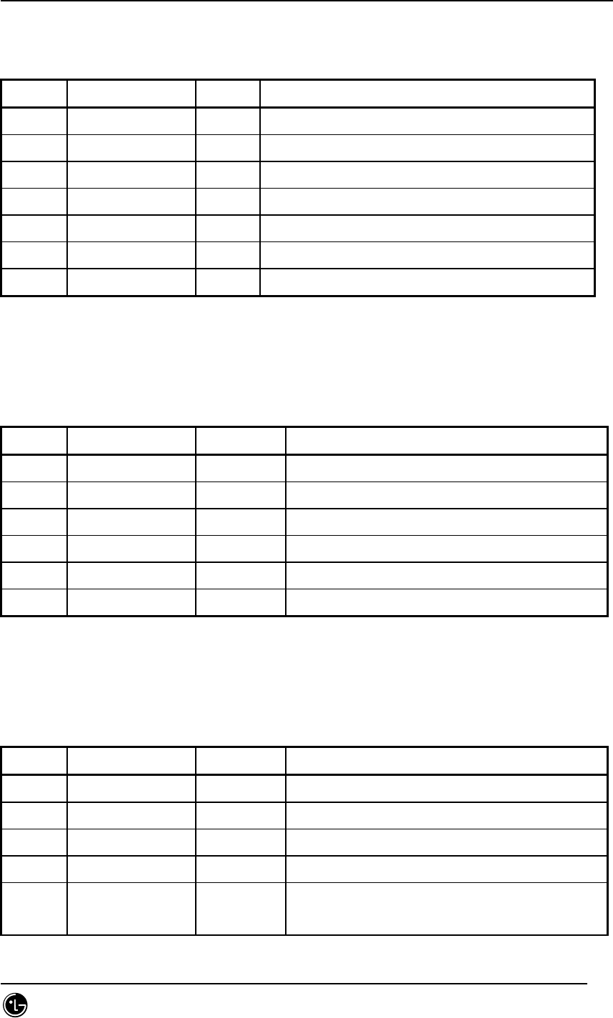
STAREX-IS BSM Manual
Page:868(877)
Issue:1.
0
SMD-011-PMA210
7.5.9.10. St_pich_data_type (Pilot Channel)
Table 7.5-88 St_pich_data_type (Pilot Channel)
Type N a m e default Remarks
BYTE SECTOR_ID 0 ~ 2
BYTE CDMACH_ID 0 ~ 7
BYTE PROC_ID PILOT CHANNEL PROCESSOR NUMBER (RCP)
BYTE SLOT PILOT CHANNEL SLOT NUMBER
BYTE PILOT_GAIN 234 pilot channel gain. in unit of dB
BYTE PILOT_TD_GAIN piot tx_diversity channel gain.
byte reserved_byte[34] 0
7.5.9.11. St_synch_data_type (Sync Channel)
Table 7.5-89 St_synch_data_type (Sync Channel)
Type N a m e default Remarks
BYTE SECTOR_ID full 0 ~ 2
BYTE CDMACH_ID full 0 ~ 7
BYTE PROC_ID SYNCH PROCESSOR NUMBER (RCP)
BYTE SLOT SYNCH SLOT NUMBER
BYTE SYNC_GAIN 159 sync channel gain. in unit of dB
byte reserved_byte[35] 0
7.5.9.12. St_pch_data_type (Paging Channel)
Table 7.5-90 St_pch_data_type (Paging Channel)
Type N a m e default Remarks
byte sector_id full 0 ~ 2
byte cdmach_id full 0 ~ 7
byte pc_id full 0 ~ 6
byte equipage Actual pc equip state
byte num_ac Access channel number per Paging Channel
Access Para AccChan

STAREX-IS BSM Manual
Page:869(877)
Issue:1.
0
SMD-011-PMA210
byte proc_id Paging channel processor number (RCP)
byte slot Paging channel slot number
BYTE PC_GAIN 217 Paging channel tx gain. in unit of dB
byte frame_duration 2 Packet frame size.
(5ms/20ms) Range : 0~4 (2:20ms)
byte data_rate 0 data rate.
Range : 0~1(0:9600bps, 1:4800bsp)
byte encoding_rate No-use 1 Convolutional channel coding rate.
byte reserved_byte[34] 0
7.5.9.13. St_qpch_data_type (Quick Paging Channel)
Table 7.5-91 St_qpch_data_type (Quick Paging Channel)
Type N a m e default Remarks
BYTE SECTOR_ID full 0 ~ 2
BYTE CDMACH_ID full 0 ~ 7
BYTE QPCH_ID full 0 ~ 2
byte equipage
BYTE PROC_ID QPCH PROCESSOR NUMBER (RCP)
BYTE SLOT QPCH SLOT NUMBER
BYTE INDICATOR_GAIN Paging indicator part gain
BYTE CCI_GAIN CCI(Configuration Change Indicator)
Gain
byte frame_duration 2 Packet frame size.
(5ms/20ms)
byte data_rate 0 data rate.
byte encoding_rate No-use Convolutional channel coding rate.
byte reserved_byt[34] 0
7.5.9.14. St_ach_data_type (Access Channel)
Table 7.5-92 St_ach_data_type (Access Channel)
Type N a m e default Remarks

STAREX-IS BSM Manual
Page:870(877)
Issue:1.
0
SMD-011-PMA210
BYTE SECTOR_ID full 0 ~ 2
BYTE CDMACH_ID full 0 ~ 7
BYTE PC_ID full 0 ~ 6
BYTE AC_ID full 0 ~ 31
byte equpage
BYTE PROC_ID ACCESS CHANNEL PROCESSOR NUMBER (RCP)
BYTE SLOT ACCESS CHANNEL SLOT NUMBER.
byte pam_int_prd No-use 2 As integer between 2~4(Walsh symbols), 8-pam
_int_prd(Walsh symbol), when detecting
access probe preamble, is dector integration
period.
word16 pam_win_len No-use 1800 As searching window size when detecting
access probe preamble, it is integer between
6~4048(1/8 chip/unit).
word16 pam_pn_offset No-use 1920 As preamble searching start pn offset value
of access probe, it is integer between 8 ~
(4092 - pam_win_ len)(1/8 PN chip/unit).
byte mul_int_prd No-use 6 As integer between 2 ~ 6(Walsh symbols), 8-
mul_int_prd(Walsh symbol) is the integration
period of detector when searching
multipathingredients while modulating
access probe data protion signal.
byte mul_win_len No-use 128 As searching window size when searching
nultipath ingredients while modulating
access probe data protion signal, it is
integer between 96~4048(1/8 PN chip/unit),
which should be lower than pam_win_len.
byte multipath_gain No-use 1 factor used to decide whether to move the
finger during demod stage based on the
result of multipath search
word16 nolock_thresh No-use 156 As threshold, it is integer between 0~65535.
word16 lock_thresh No-use 156 As threshold, it is integer between 0~65535.
word16 combine_thresh No-use 156 Threshold used to enable combining of a
finger when it is in LOCK state.
WORD16 SRCH_START_OFFSET 0 Search Start Offset. in units of chipx8
Range : 0~4096(Chipx8 units)

STAREX-IS BSM Manual
Page:871(877)
Issue:1.
0
SMD-011-PMA210
WORD16 SRCH_WIN_SIZE 4(access) Search Window Size. in units of 64PN chip.
Range : 1~32(64 PN Chips units)
byte reserved_byte[35] 0
7.5.9.15. St_apich_data_type (Auxiliary Pilot Channel)
Table 7.5-93 St_apich_data_type (Auxiliary Pilot Channel)
Type N a m e default Remarks
BYTE SECTOR_ID full 0 ~ 2
BYTE CDMACH_ID full 0 ~ 7
BYTE PROC_ID APICH PROCESSOR NUMBER (RCP)
BYTE SLOT APICH SLOT NUMBER
byte reserved_byte[32] 0
7.5.9.16. St_bcch_data_type (Broadcast Channel)
Table 7.5-94 St_bcch_data_type (Broadcast Channel)
Type N a m e default Remarks
BYTE SECTOR_ID full 0 ~ 2
BYTE CDMACH_ID full 0 ~ 7
BYTE BCCH_ID full 0 ~ 6
byte equipage
BYTE PROC_ID Broad CHANNEL PROCESSOR NUMBER (RCP)
BYTE SLOT Broad CHANNEL SLOT NUMBER
byte TX_GAIN
byte SPREADING_RATE
byte OTD
byte SR1_BCN
byte SR1_BRAT
byte SR1_NON_OTD_INCL
byte SR1_CDMA_FREQ_NON
_OTD
byte SR1_BCCH_RATE_NON
_OTD

STAREX-IS BSM Manual
Page:872(877)
Issue:1.
0
SMD-011-PMA210
byte SR1_OTD_INCL
byte SR1_CDMA_FREQ_OTD
byte SR1_BCCH_RATE_OTD
byte SR3_CAP_IND
byte SR3_CDMA_FREQ
byte SR3_BCN
byte SR3_BRAT
byte frame_duration Packet frame size.
(5ms/20ms)
byte data_rate data rate.
byte radio_configurati
on
(encoding_rate)
Convolutional channel coding rate. Radio
configuration
byte reserved_byte[34] 0
7.5.9.17. St_cpch_data_type (Common Power Control Channel)
Table 7.5-95 St_cpch_data_type (Common Power Control Channel)
Type N a m e default Remarks
BYTE SECTOR_ID full 0 ~ 2
BYTE CDMACH_ID full 0 ~ 7
BYTE CPCH_ID full 0 ~ 6
byte equipage
BYTE PROC_ID CPCH PROCESSOR NUMBER (RCP)
BYTE SLOT CPCH SLOT NUMBER
byte frame_duration Packet frame size.
(5ms/20ms)
byte data_rate data rate.
byte radio_configurati
on
(encoding_rate)
Convolutional channel coding rate. Radio
configuration
byte reserved_byte[32] 0
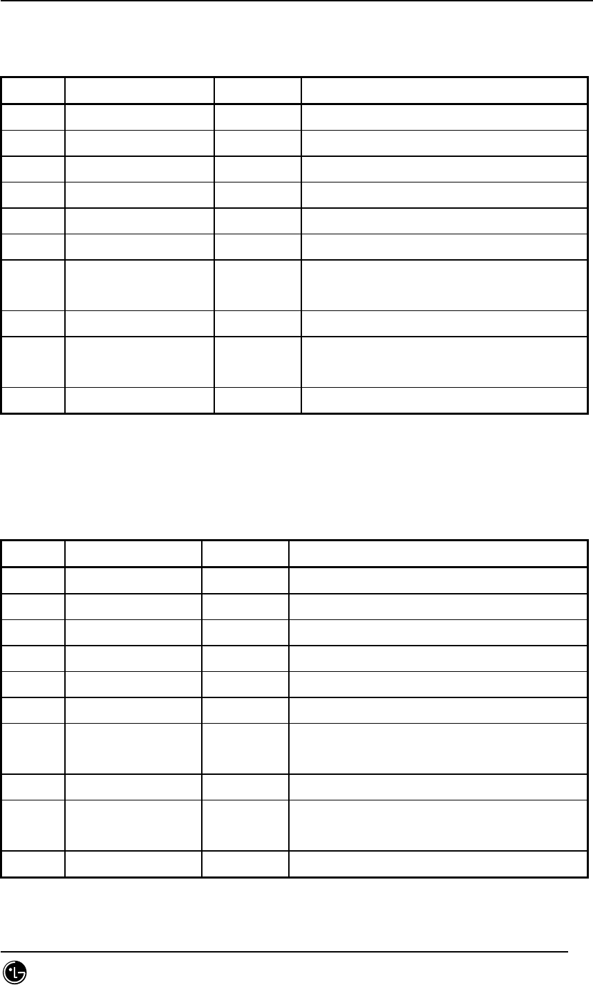
STAREX-IS BSM Manual
Page:873(877)
Issue:1.
0
SMD-011-PMA210
7.5.9.18. St_cach_data_type (Common Assignment Channel)
Table 7.5-96 St_cach_data_type (Common Assignment Channel)
Type N a m e default Remarks
BYTE SECTOR_ID full 0 ~ 2
BYTE CDMACH_ID full 0 ~ 7
BYTE CACH_ID full 0 ~ 6
byte equipage
BYTE PROC_ID CACH PROCESSOR NUMBER (RCP)
BYTE SLOT CACH SLOT NUMBER
byte frame_duration Packet frame size.
(5ms/20ms)
byte data_rate data rate.
byte radio_configuration
(encoding_rate)
Convolutional channel coding rate.
Radio configuration
byte reserved_byte[32] 0
7.5.9.19. St_fccch_data_type (Forward Common Control Channel)
Table 7.5-97 St_fccch_data_type (Forward Common Control Channel)
Type N a m e default Remarks
BYTE SECTOR_ID full 0 ~ 2
BYTE CDMACH_ID full 0 ~ 7
BYTE FCCCH_ID full 0 ~ 6
byte equipage
BYTE PROC_ID FCCCH PROCESSOR NUMBER (RCP)
BYTE SLOT FCCCH SLOT NUMBER
byte frame_duration Packet frame size.
(5ms/20ms)
byte data_rate Data rate.
byte radio_configuration
(encoding_rate)
Convolutional channel coding rate. Radio
configuration
byte reserved_byte[32] 0
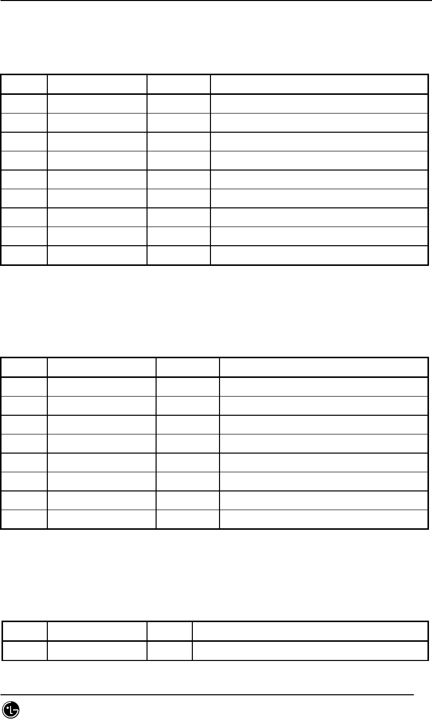
STAREX-IS BSM Manual
Page:874(877)
Issue:1.
0
SMD-011-PMA210
7.5.9.20. St_each_data_type (Enhanced Access Channel)
Table 7.5-98 St_each_data_type (Enhanced Access Channel)
Type N a m e default Remarks
BYTE SECTOR_ID full 0 ~ 2
BYTE CDMACH_ID full 0 ~ 7
BYTE FCCCH_ID or CACH_ID full 0 ~ 6
BYTE EACH_ID full 0 ~ 31
byte equipage
BYTE DUPLEX_ID 0 ~ 1 Redundancy
BYTE PROC_ID EACH PROCESSOR NUMBER (RCP)
BYTE SLOT EACH SLOT NUMBER
BYTE reserved_byte[33] 0
7.5.9.21. St_rccch_data_type (Reverse Common Control Channel)
Table 7.5-99 St_rccch_data_type (Reverse Common Control Channel)
Type N a m e default Remarks
BYTE SECTOR_ID full 0 ~ 2
BYTE CDMACH_ID full 0 ~ 7
BYTE FCCCH_ID or CACH_ID full 0 ~ 6
BYTE RCCH_ID full 0 ~ 31
byte equipage
BYTE PROC_ID EACH PROCESSOR NUMBER (RCP)
BYTE SLOT EACH SLOT NUMBER
BYTE reserved_byte[34] 0
7.5.9.22. St_sector_cdmach_data_type
Table 7.5-100 St_sector_cdmach_data_type
type Name default Remarks
byte sector_id full

STAREX-IS BSM Manual
Page:875(877)
Issue:1.
0
SMD-011-PMA210
byte cdmach_id full
byte ocns_enable 0 0: Ocns Enabled 1: Ocns Disabled
byte num_of_ocns_ch 0 Ocns Call Number ( 0 ~ 20 )
byte ocns_test_data 5 Test Data Rate ( 0 ~ 5 )
( B, 1/8, 1/4, 1/2, 1, V)
word16 ocns_so 0x801f Service Option
[ Markov(8002, 801f), LB(2,9) ]
byte block_state 0 0: Unblock, 1: Block
If current sector FA is ‘block’, MS regards
no FA residing in channel list.
byte reserved_byte[32] 0
7.5.9.23. St_HW_reset_type
Table 7.5-101 St_HW_reset_type
type Name default Remarks
byte dummy_key 0
byte shlf_pwr[20] CSD : BSBB(0), RCBB0(1), RCBB1(2),
RCBB2(3), RCBB3(4)
COU : BCCB0(5), BCCB1(6), BCCB2(7),
BCCB3(8)
9 ~ 19 : Reseved
byte bspa[4][2] 0
byte lica[4] 0
byte aria[4] 0
byte bada 0
byte risa 0
byte bota 0
byte dran 0
byte rcpa[4][2] 0
byte mcpa[4][10] 0
byte buda[4][6] 0
byte paca[4] 0
byte pa[6][6] 0
byte bcra[2] 0

STAREX-IS BSM Manual
Page:876(877)
Issue:1.
0
SMD-011-PMA210
byte bppa
byte reserved_byte[23] 0
7.5.9.24. St_Chip_pwr_cntl_para_data( 0:FCH , 1:SCH, 2:SCCH, 3:DCCH )
Table 7.5-102 St_Chip_pwr_cntl_para_data
Type N a m e default Remarks
byte Dummy 0
byte Channel_pwr[MAX_CH_T
YPE(4)]
224 Forward Traffic Channel Tx Power
0(-63.5dB) ~ 127(0dB). 0.5dB step
byte Data_gain No-use Data Gain to be added to the Channel
Power
-31.75dB ~ 31.75dB. 0.5dB step
byte Pwr_cntl_gain No-use Power Control Sub-channel Gain to be
added to the Channel. –31.75dB ~ 31.75dB,
0.5dB step.
byte Min_gain[MAX_CH_TYPE
(4)]
150 Forward Traffic Channel Power Minimum
Value
byte max_gain[MAX_CH_TYPE
(4)]
224 Forward Traffic Channel Power Maximum
Value
byte step_up_size 4 Forward Traffic Channel Power Control
step up size. 0(0dB) ~ 15(3.75dB), 0.25dB
step
byte step_dn_size 4 Forward Traffic Channel Power Control
step down size. 0(0dB) ~ 15(3.75dB),
0.25dB step
byte fpc_punc_mode 0 FPC(Forward Power Control) Puncture Mode.
Same as fpc_mode of St_pwr_cntl_para_type
byte rpc_punc_mode 0 RPC(Reverse Power Control) Puncture Mode.
byte pwr_cntl_set_point 219 RPC Set Point(Threshold)
0(-63.75dB) ~ 255(0dB), 0.25dB step
byte pwr_cntl_pattern 3 Power Control Up/Down pattern to be used
when no fingers are combining
byte Reserved_byte[32]

STAREX-IS BSM Manual
Page:877(877)
Issue:1.
0
SMD-011-PMA210
7.6. Abbreviations
Table 7.6-1 Abbreviations in IS-2000 system
Abbreviations Description
ABID Alarm Buffer Inerface Daughter board
ACBB AAL 2 Control Back Board
ALP ATM Low speed subs. Processor
AUBB ATM low speed sUbscriber Back Board
AXBB ATM Switch Back Board
BABB BTS ATM Network BackBoard
BADA Base Station Analyze & Diagnostic Assembly
BANU BTS ATM Network Unit
BCRA BTS Cell Router Board Assembly
BMS Base station Management System
BPPA BTS Peripheral Processor Board Assembly
BSC Base Station Controller
BSM Base Station Manager
BSS CAN Network control Processor
BSPU BTS Signaling Processor Unit
BTGU BTS Timing Generation Unit
BTS Base Station Tranceiver Subsystem
BUDA Base Station Sector conversion&Up/Down Converter Assembly
CAN Central ATM Network
CBBB Control and Protocol Block BackBoard
CCP Call Control Processor
CDMB Configuration & Data Management Block
CNP CAN Network control Processor
CRP Cell Router Control Processsor
DBPA Digital BaseBand Processing Board Assembly
DCBU Digital Channel Bank Unit
DCIB Data Communication Interface Block
FER Fault Error Rate

STAREX-IS BSM Manual
Page:878(877)
Issue:1.
0
SMD-011-PMA210
FERA Fast Ethernet Routing Board Assembly
FETD Fast Ethernet Termination Board Assembly
GPS-D global Positioning System - Distribution
GPS-R Global Positioning System - Receiver
GUI Graphic User Interface
HDLC High-level Data Link Control
LICA Line Interface Controller Board Assembly
LPA Linear Power Amplifier
MAC Medium Access Control
MMI Man Machine Interface
NCP Network Control Processor
OCNS Orthogonal Channel Noise Simulator
PACA Power Adjustment Control Assembly
PCP Protocol Control Processor
RCCA Radio channel Processing Board Assembly
RCMD Remote Control Module Daughter Board
RNS Radio Network Subsystem
SEBB Selecter bank Back Board
SMP Selector bank Master Processor
STMB Status Management Block
TRMB TRouble Mamagement Block
UCPA Universal Contrl Processor Board Assembly
VCBB VoCoder bank Back Board
VMP Vocoder bank Master Processor