LG Electronics USA 3G1XINBTS STAREX-IS 1900 Indoor BTS User Manual STAREX IS User s Manual
LG Electronics USA STAREX-IS 1900 Indoor BTS STAREX IS User s Manual
UserManual.wiki
>
LG Electronics USA
>
3G1XINBTS User Manual
>
Users Manual Part D
Contents
1.
Users Manual Part A
2.
Users Manual Part B
3.
Users Manual Part C
4.
Users Manual Part D
5.
Users Manual Part E
6.
Users Manual Part F
7.
Users Manual Part G
Users Manual Part D
Navigation menu
Upload a User Manual
Namespaces
Wiki Guide
HTML
PDF
Info
Views
User Manual
Discussion / Help
Navigation
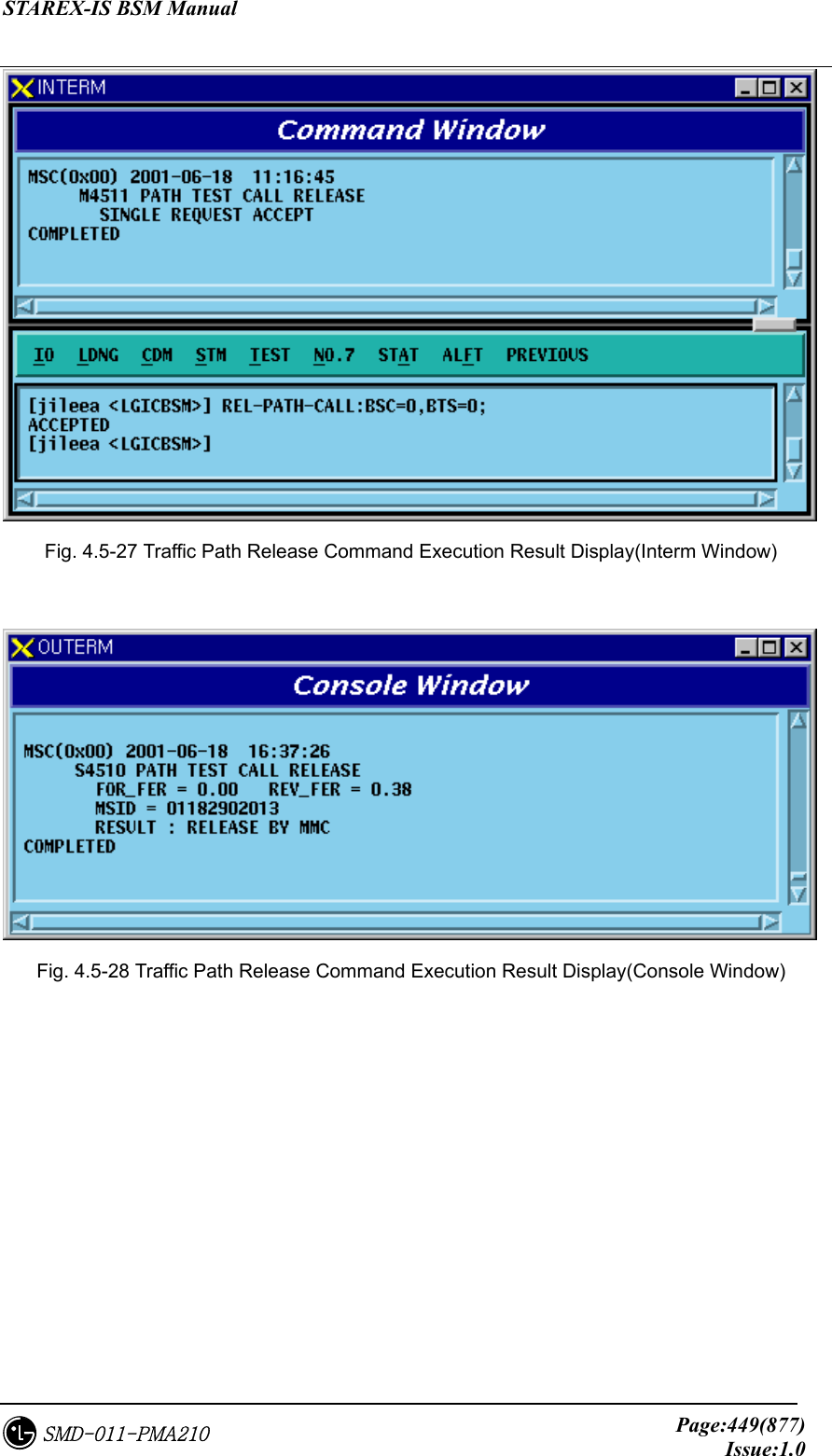
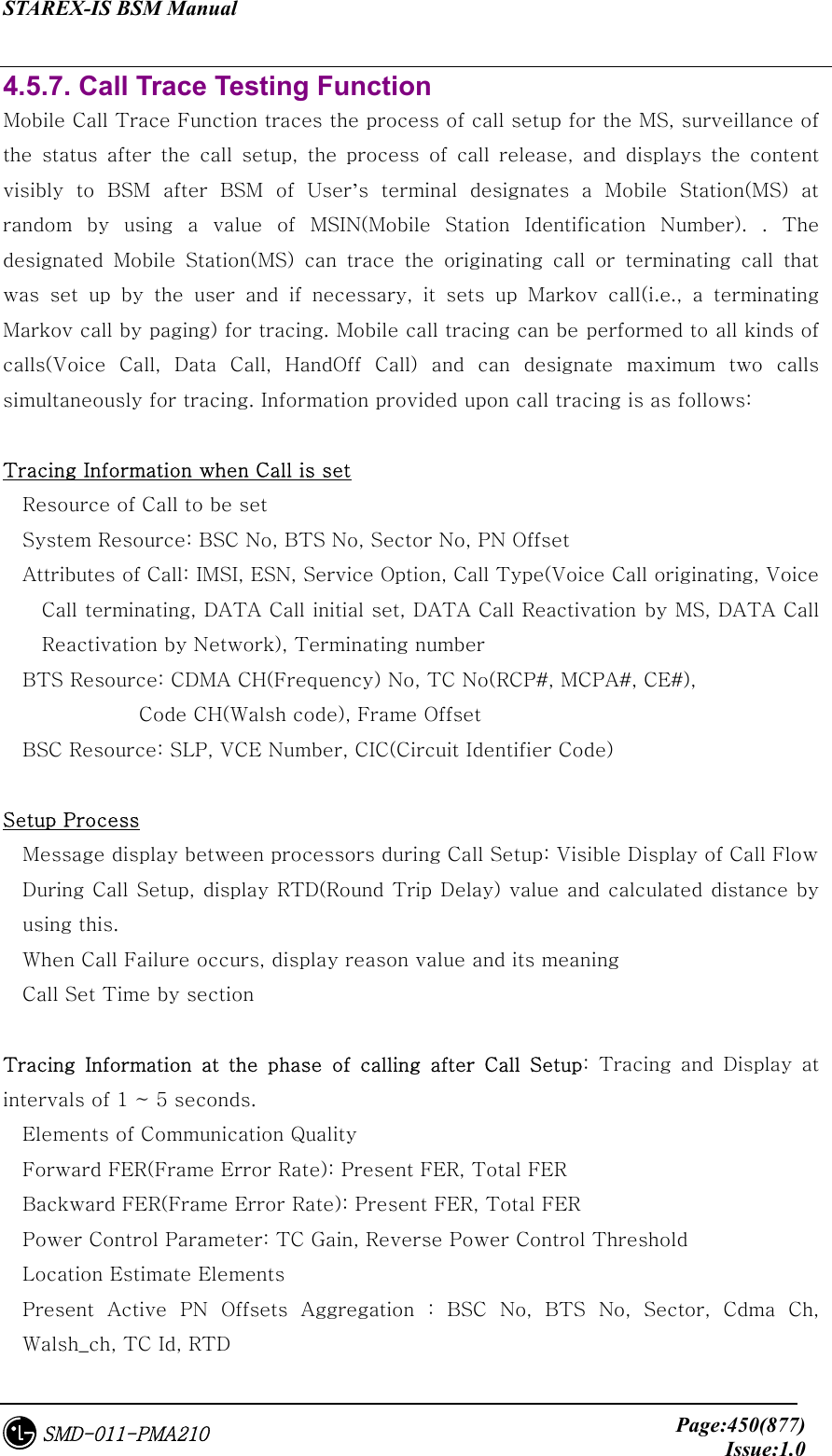
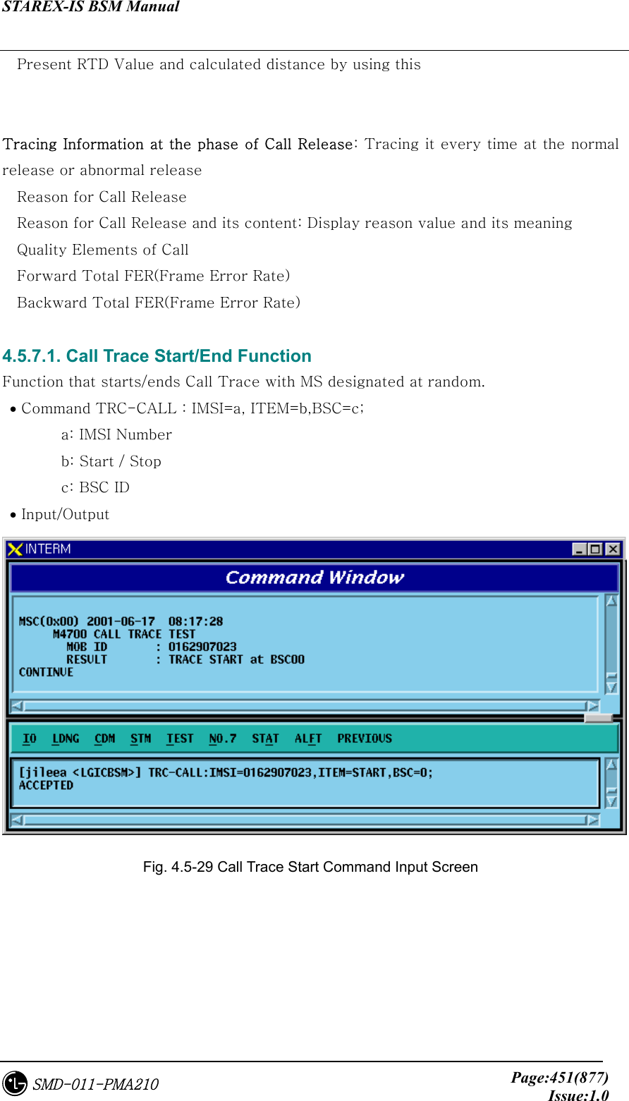
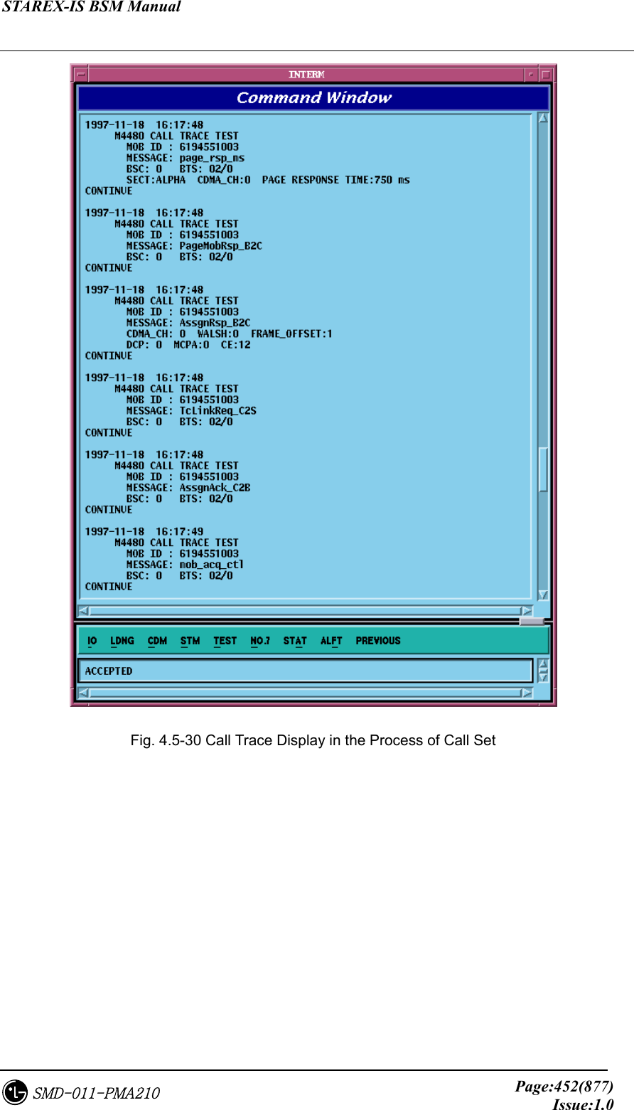
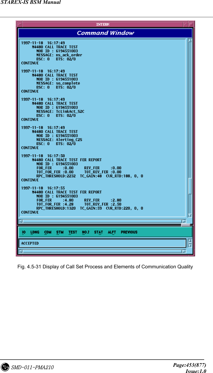
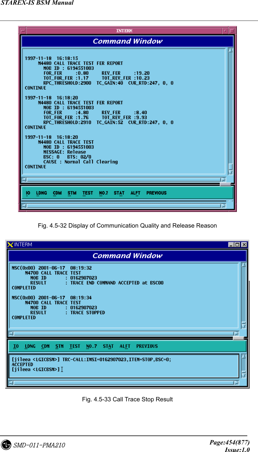
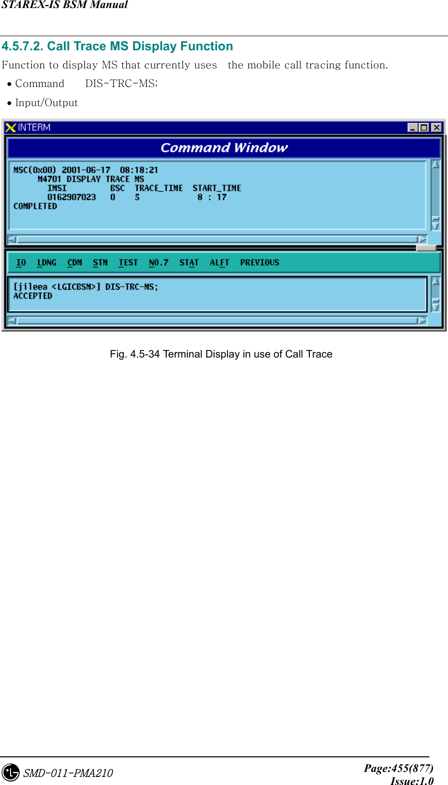
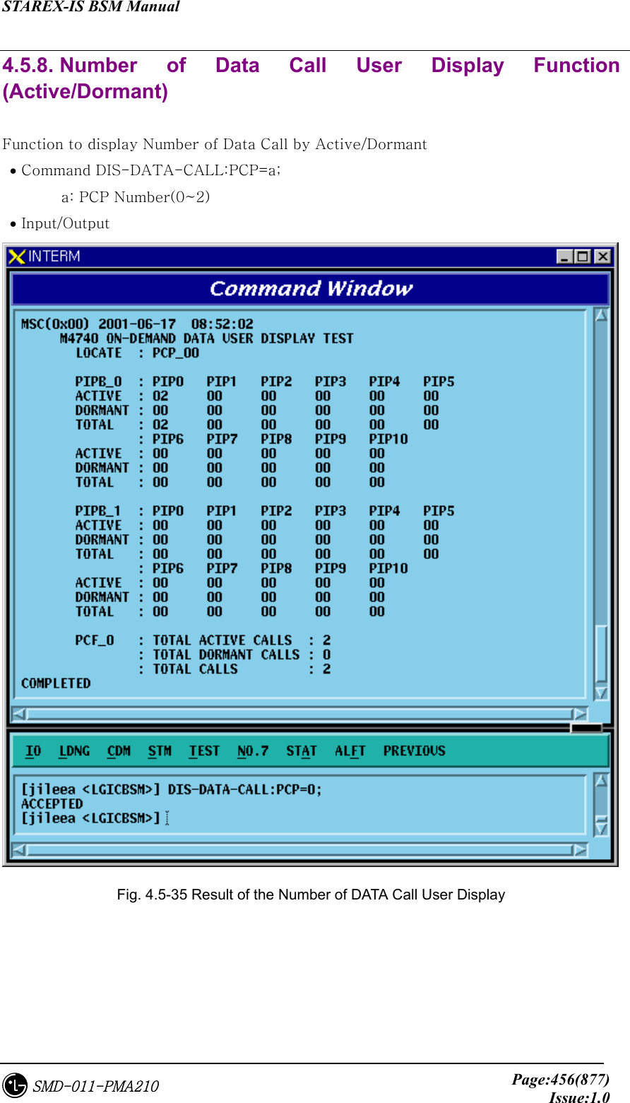
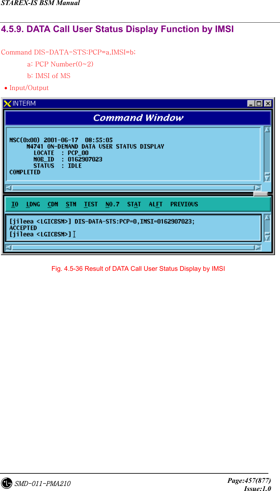
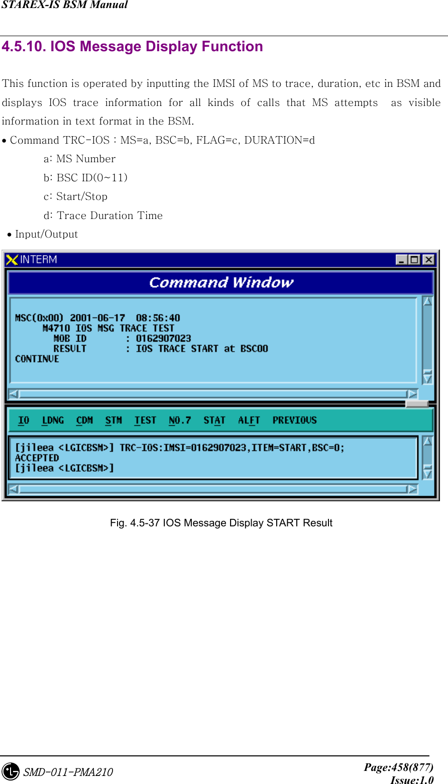
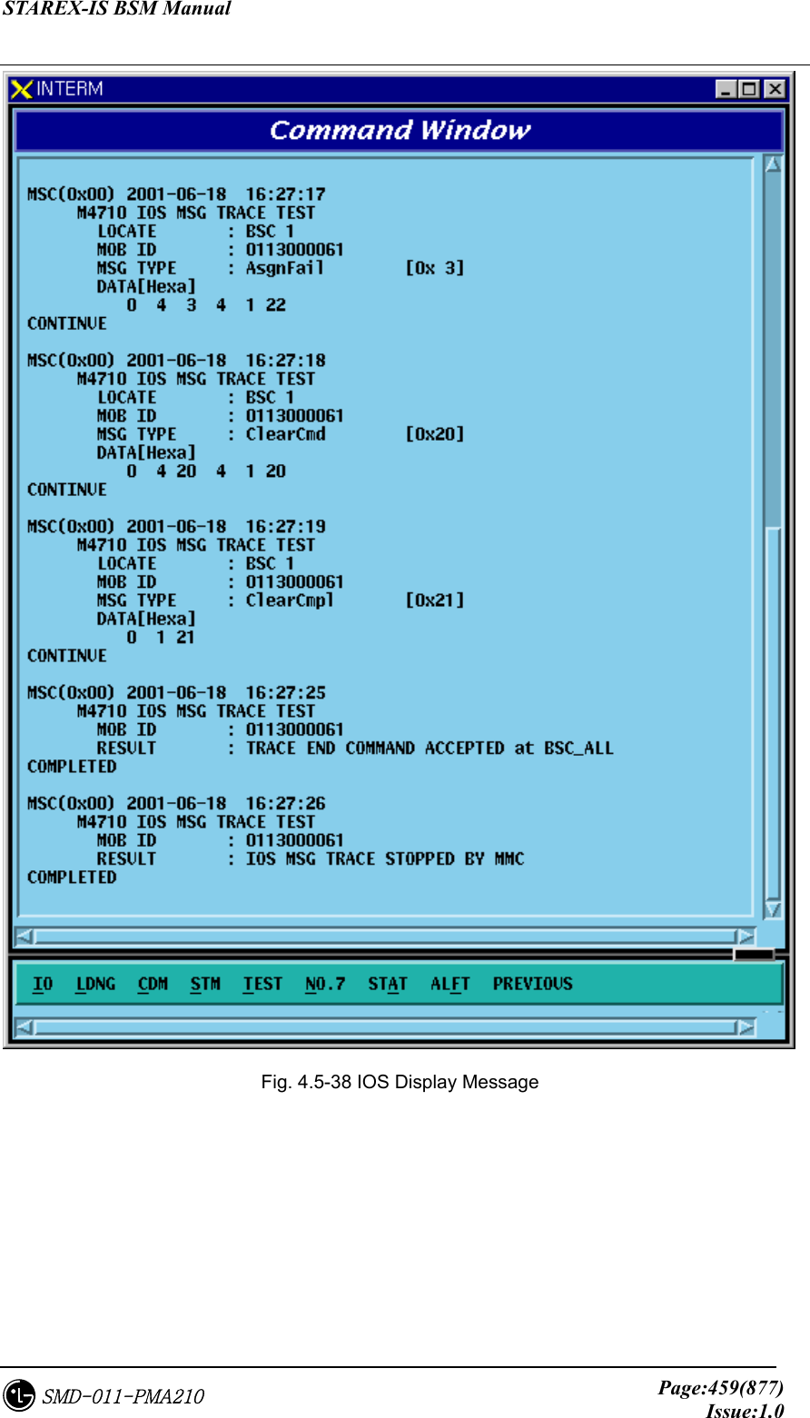
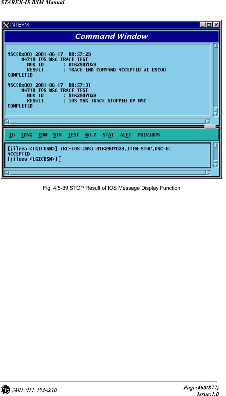
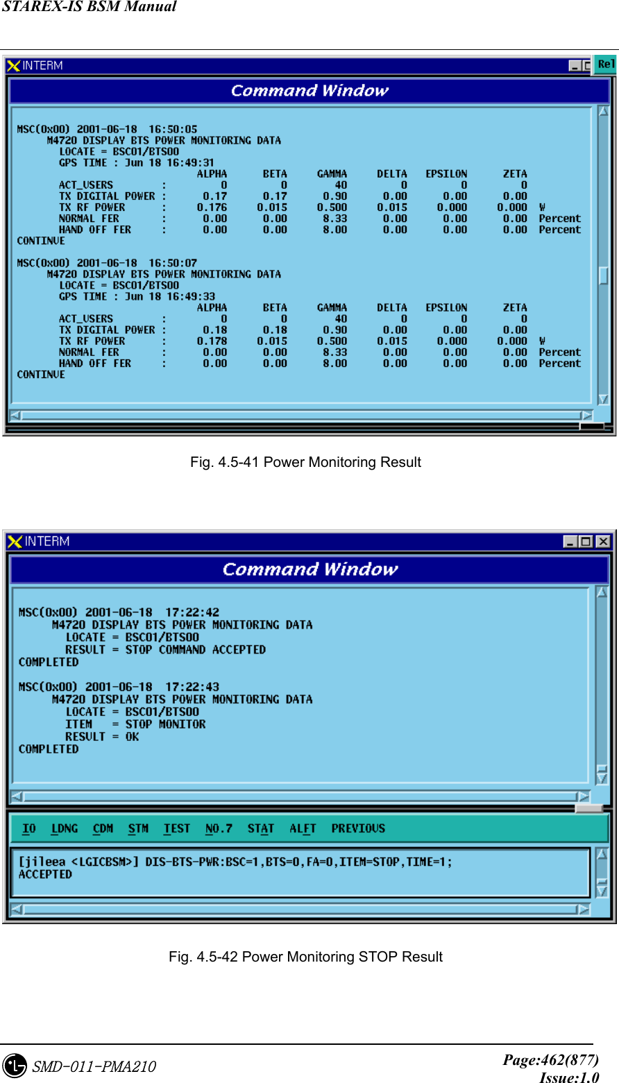
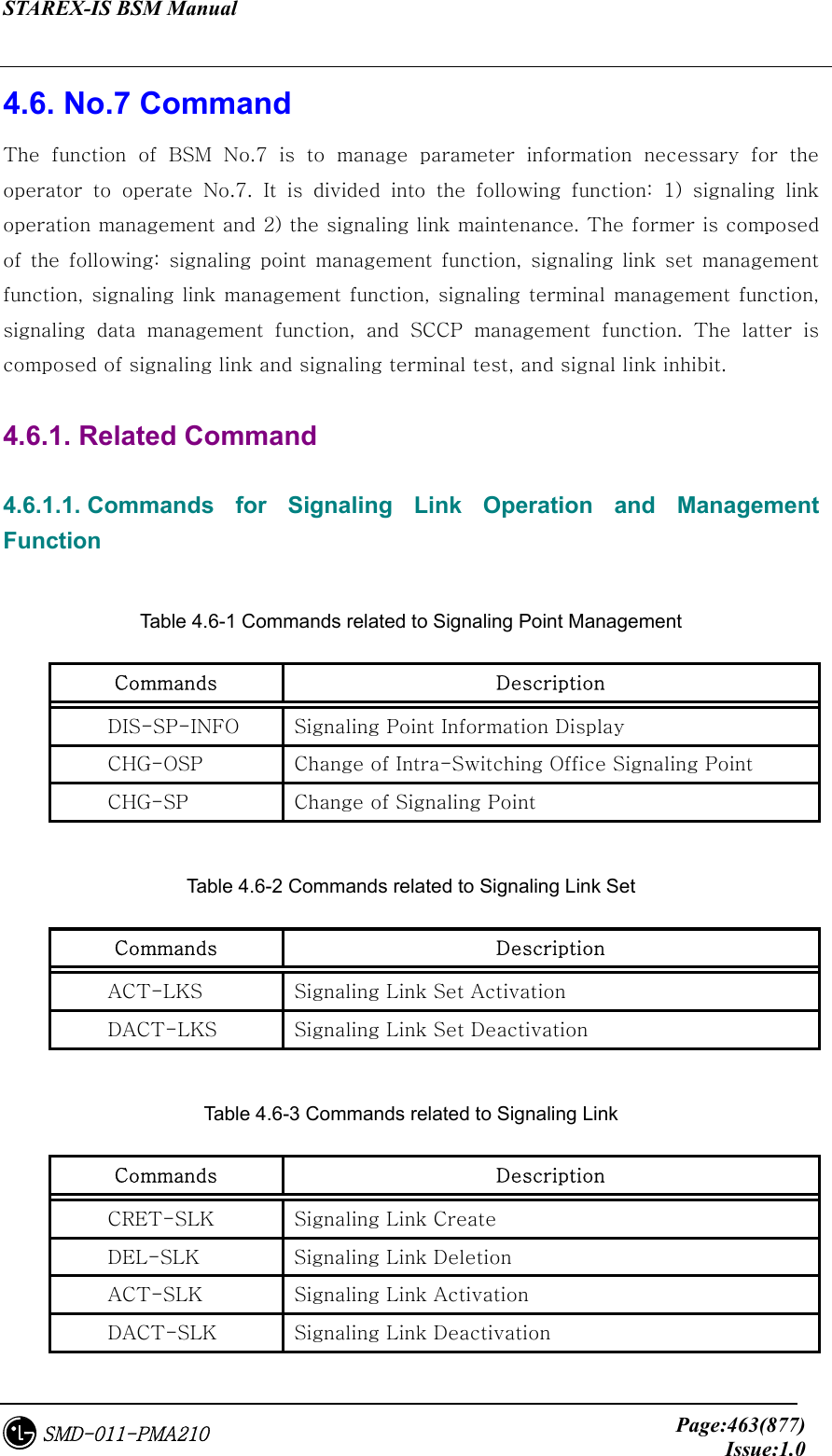
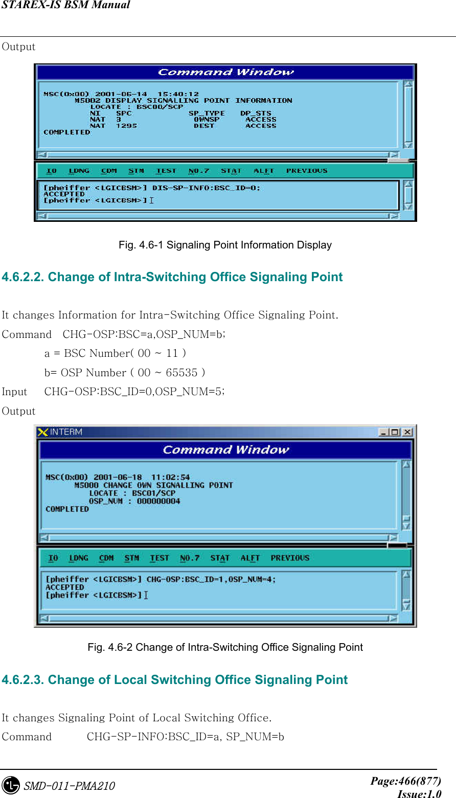
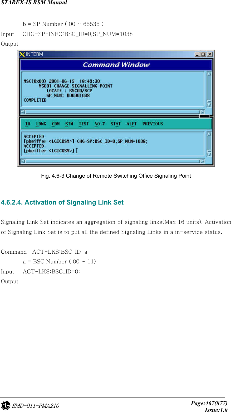
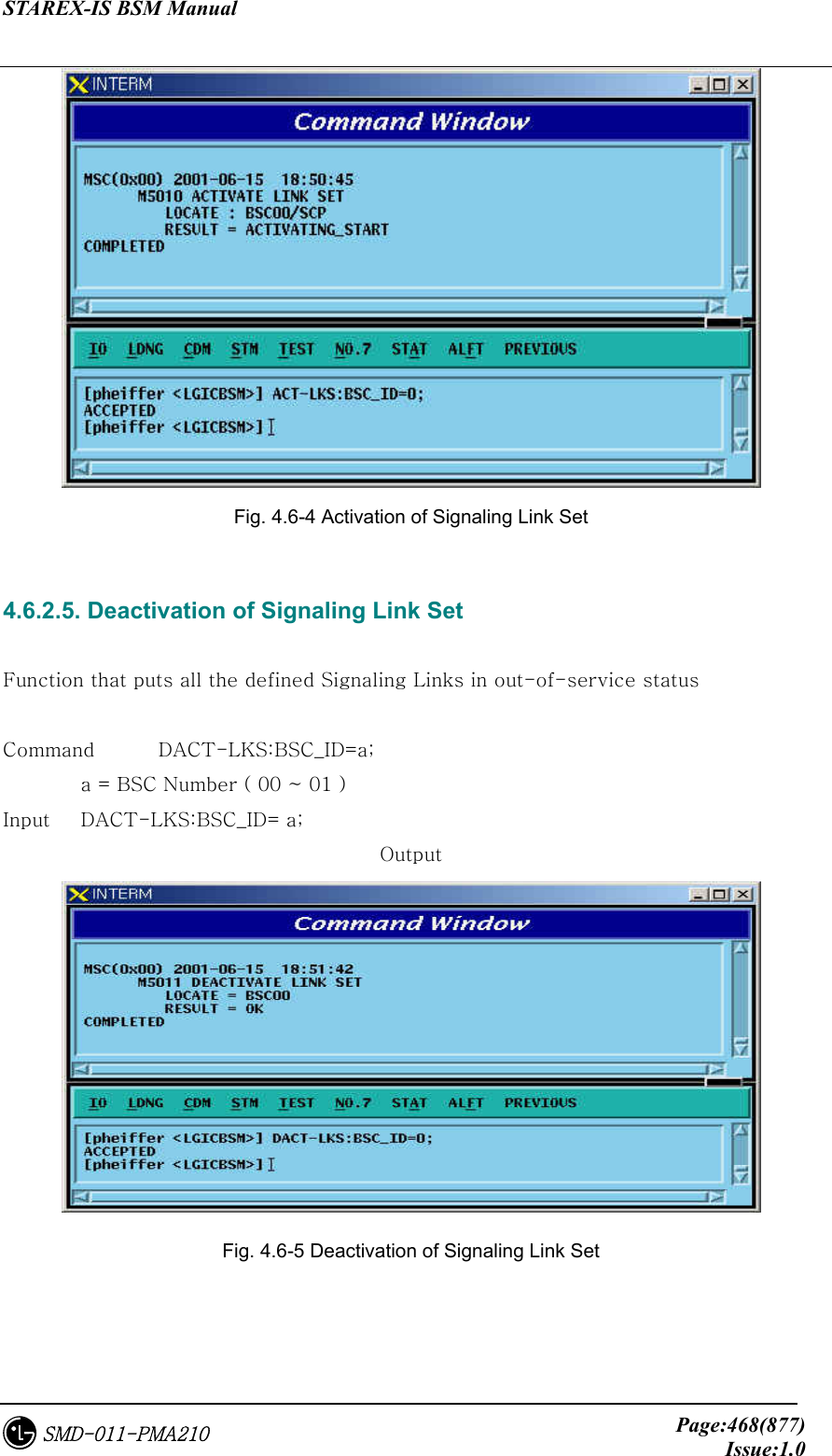
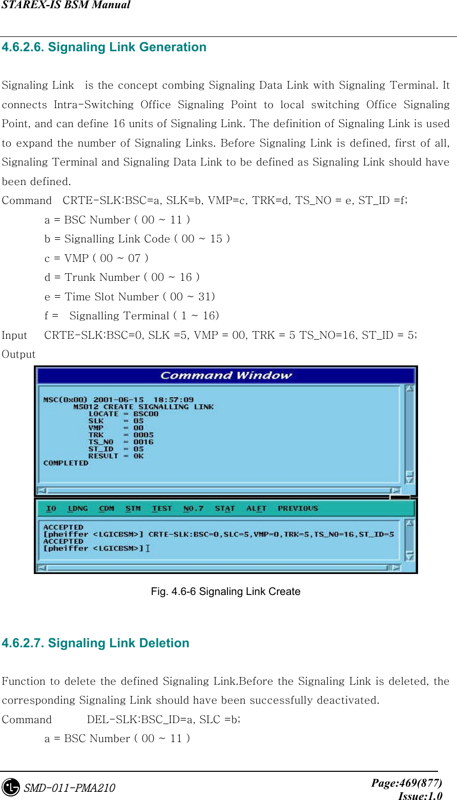
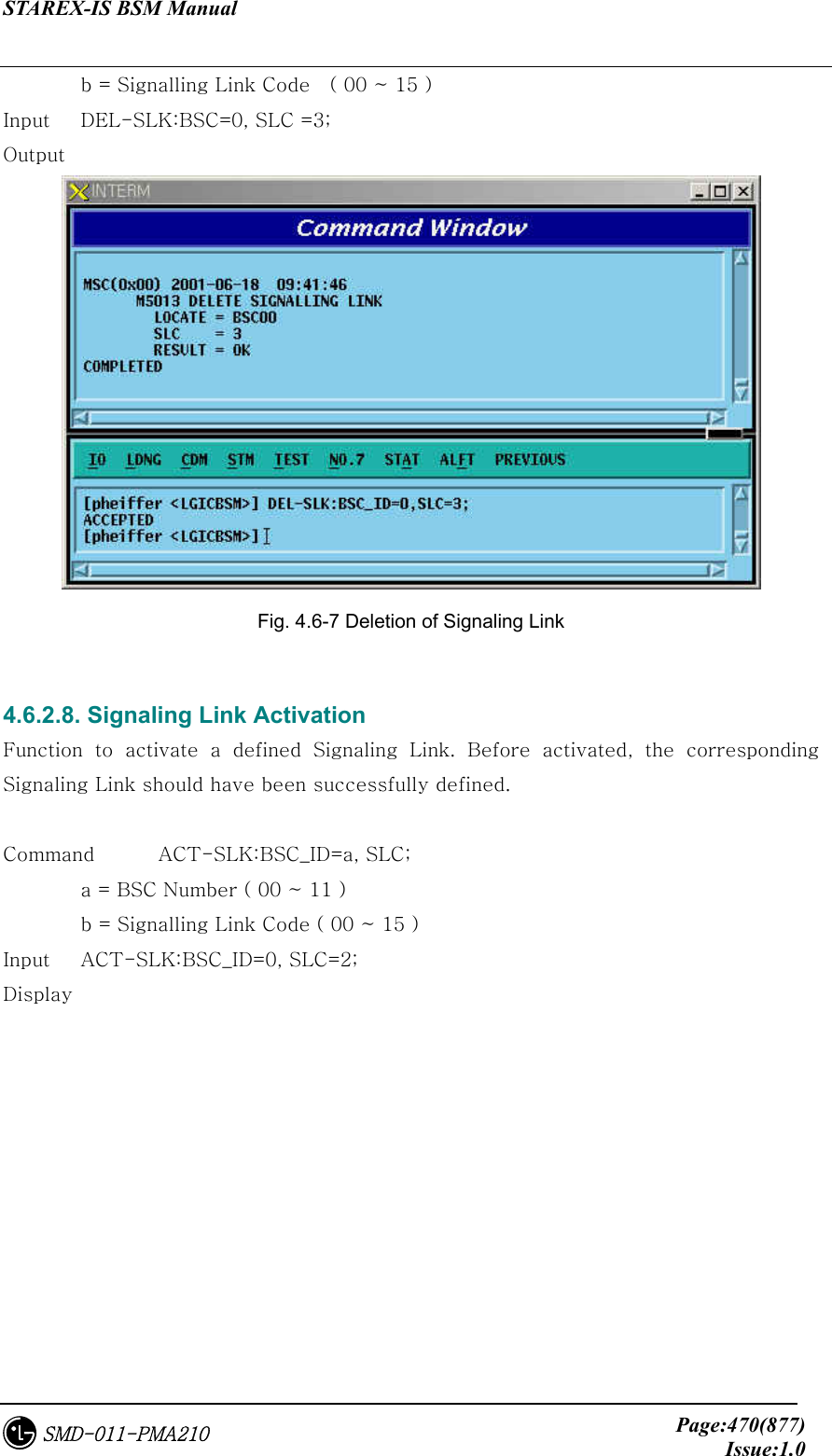
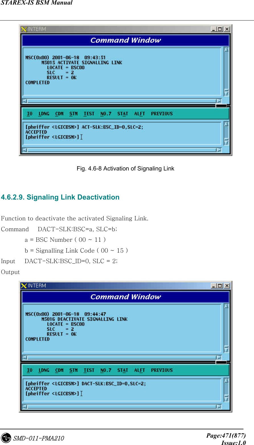
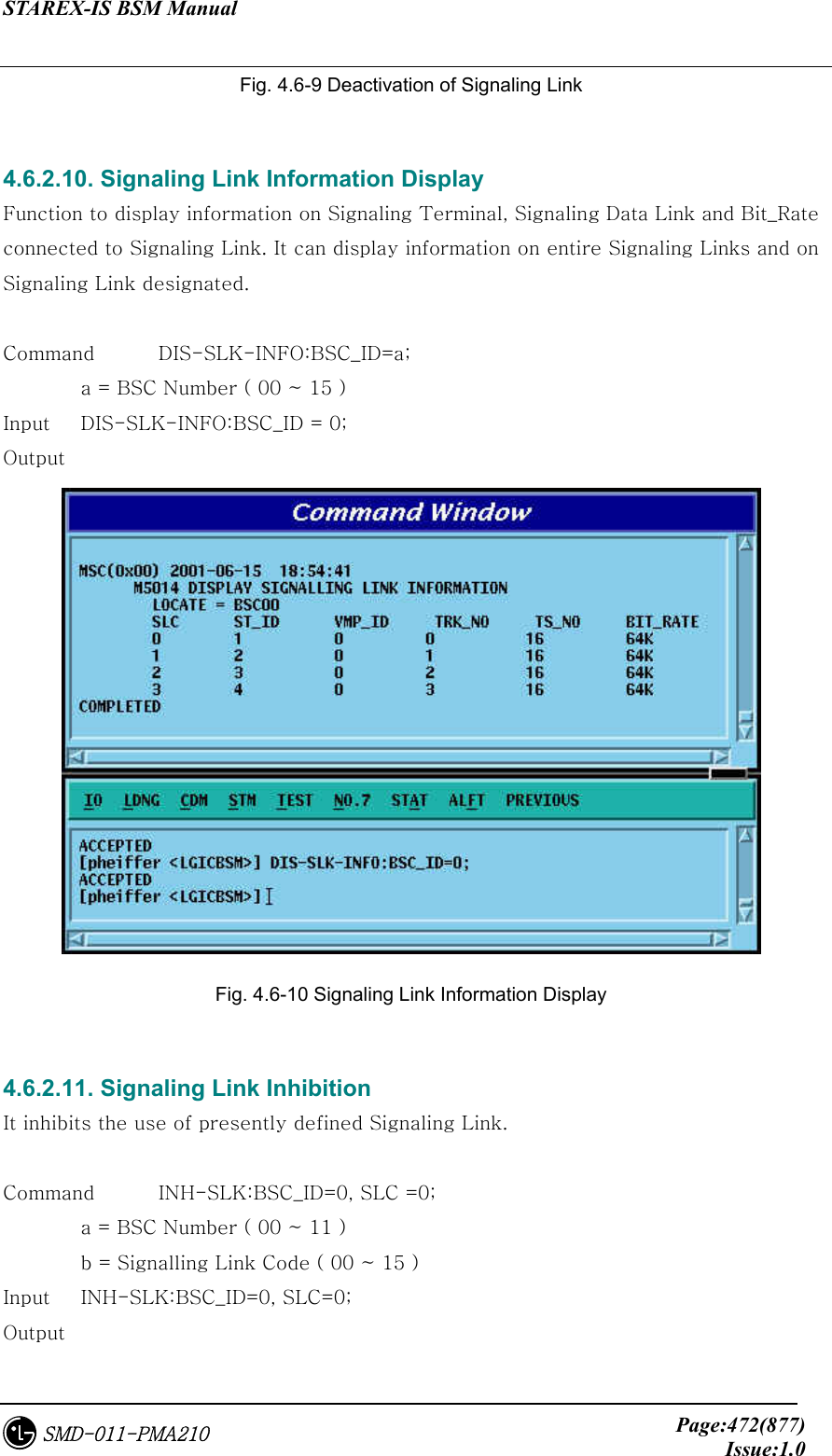
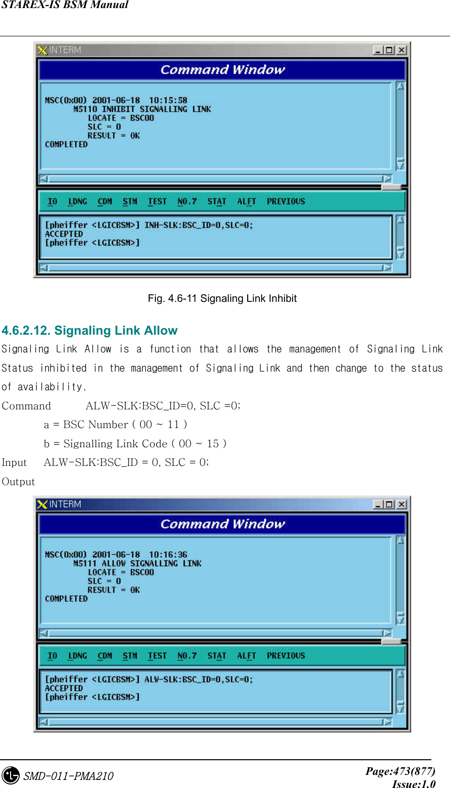
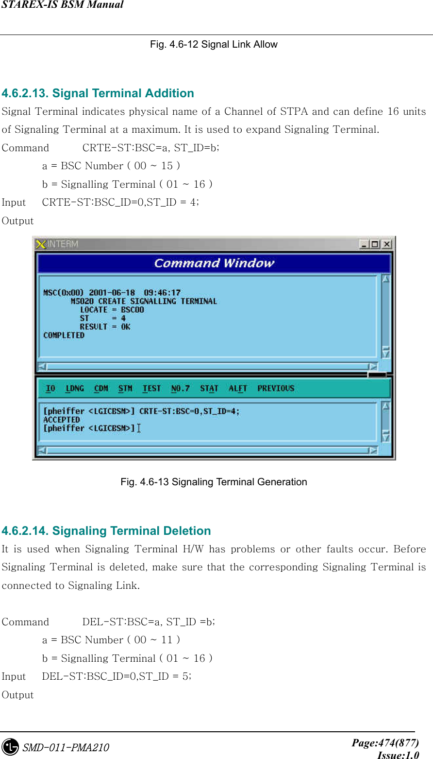
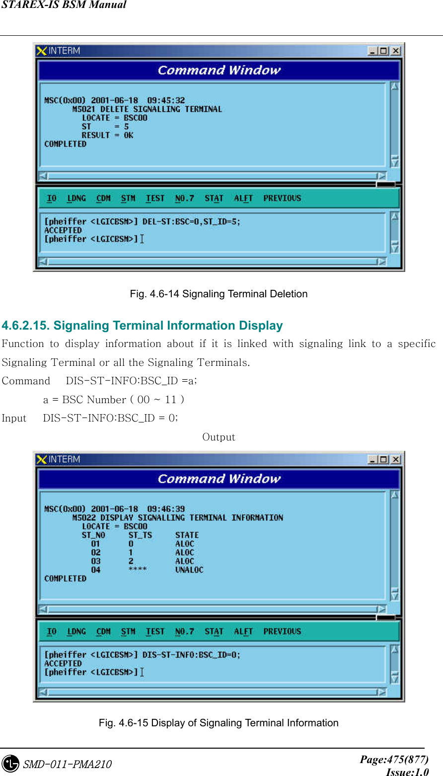
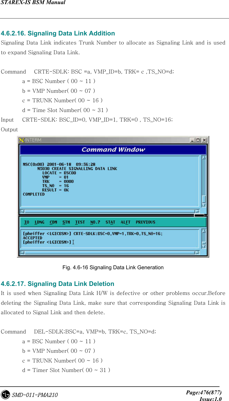
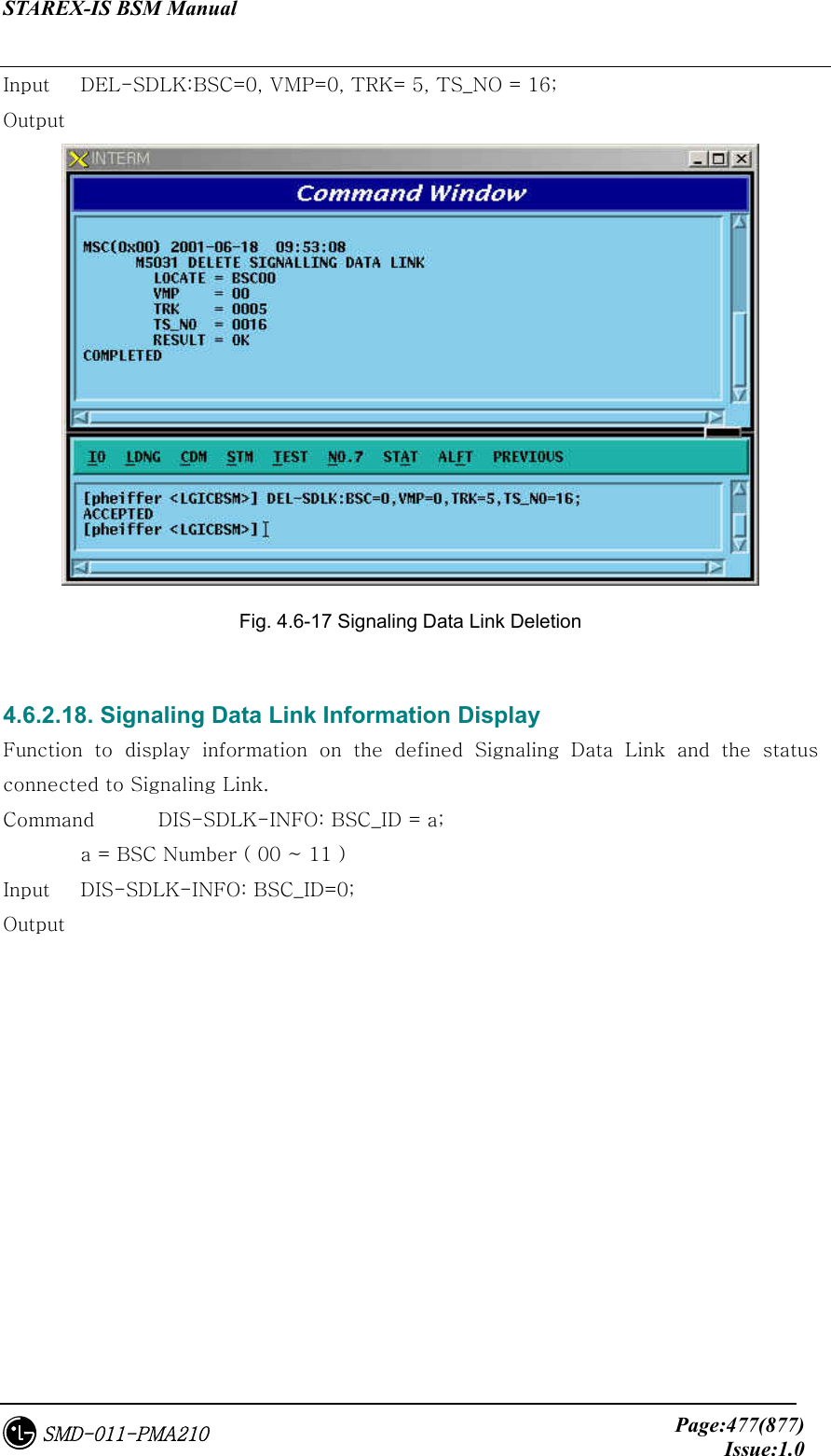
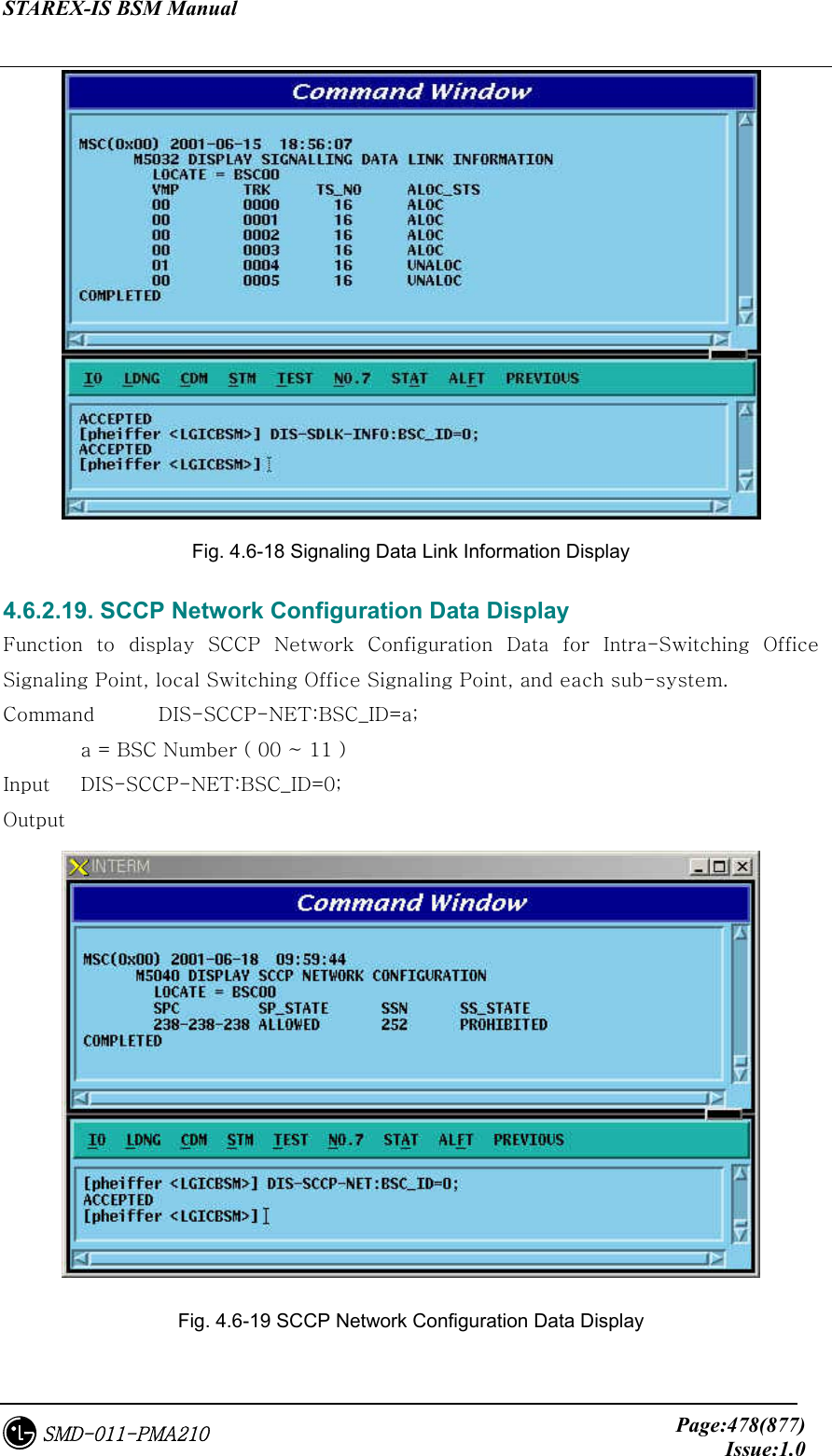
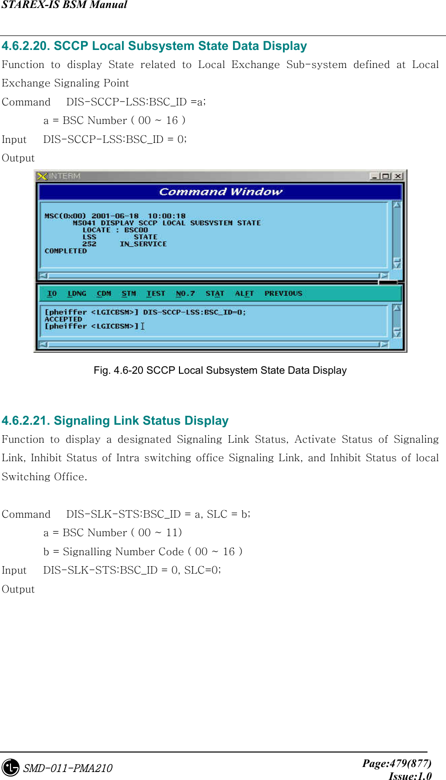
![STAREX-IS BSM Manual Page:461(877)Issue:1.0SMD-011-PMA210 4.5.11. POWER MONITORING Function Function to check the BTS power control in BSM • Command DIS-BTS-PWR:BSC=a,BTS=b,ITEM=c,[TIME=d]: a: BSC ID(0~11) b: BTS ID(0~47) c: Stop/Start d: Duration Time(1~100 min) • Input/Ouput Fig. 4.5-40 Power Monitoring START Result](https://usermanual.wiki/LG-Electronics-USA/3G1XINBTS.Users-Manual-Part-D/User-Guide-178304-Page-13.png)