Lutron Electronics 0062 Dimmer or Switch User Manual 5
Lutron Electronics Company Inc Dimmer or Switch 5
Contents
User Manual 5
Designer-Style RF Maestro®
Dimmers
HRD-6D, HRD-6ND, HRD-10D, HRD-10ND
Switch
HRD-8ANS
Fan Speed Control
HRD-2ANF
120 V 50 / 60 Hz
Installation Instructions
Please Read Before Installing
Multigang Installations
In multigang installations, several controls
are grouped horizontally in one multigang
wallbox.
When combining controls in a wallbox,
derating is required; however, no derat-
ing is required for Fan Speed Controls or
Remotes.
Derating Chart
Control Load
Type End of
Gang Middle of
Gang
HRD-6D,
HRD-6ND
Incand. 500 W 400 W
MLV 400 W /
500 VA 300 W /
400 VA
HRD-10D,
HRD-10ND
Incand. 800 W 650 W
MLV 600 W /
800 VA 500 W /
650 VA
HRD-8ANS Lighting 6.5 A 5 A
Motor 5.8 A 5 A
HRD-2ANF Ceiling
Fan 2 A 2 A
Note: -8ANS controls have fins that need
to be removed for multigang installations.
-6D, -6ND, -10D, -10ND, and -2ANF
controls do not have fins that need to be
removed for multigang installations.
Short Circuit Check: Check the instal-
lation for short circuits before installing
control(s). With power OFF, install stan-
dard mechanical switch(es) between Hot
and load. Restore power. If lights or fan
do not work or a breaker trips, check
wiring. Correct wiring and check again.
Install control(s) only when short is no lon-
ger present. Warranty is void if control is
turned ON with a shorted circuit.
1. Turn power OFF at fusebox or circuit
breaker.
2. Prepare wires. When making wire con-
nections, follow the recommended strip
lengths and combinations for the sup-
plied wire connector. Note: Wire con-
nectors provided are suitable for copper
wire only.
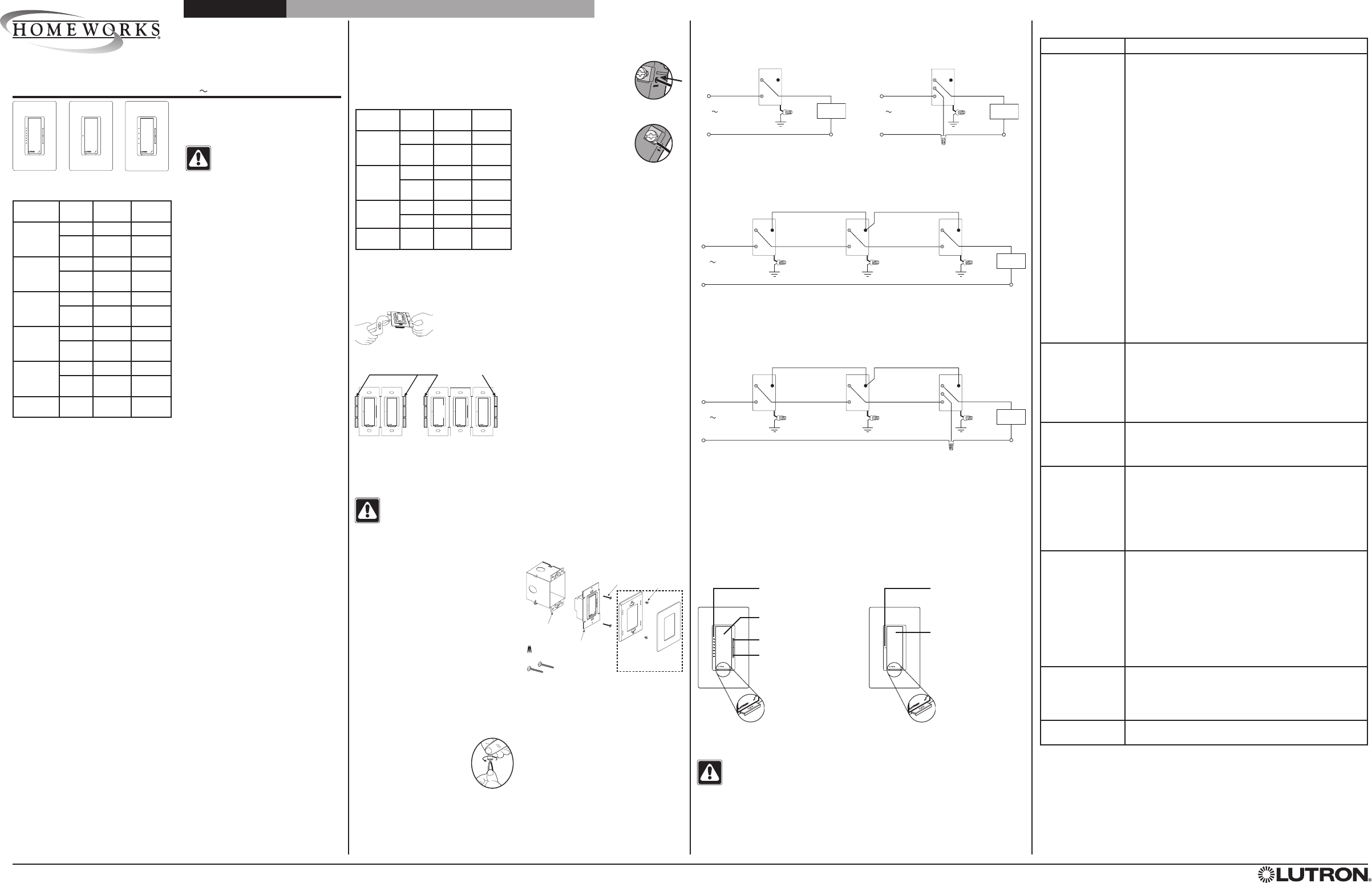
Multi-Location Installation2
-6D, -10D with HD-RD
Wiring Diagram 3
Single Location Installation with Neutral
-6ND, -10ND, -2ANF, -8ANS
120 V
50 / 60 Hz
Brass
Silver
Black
Blue
Tighten1
Green
Ground
Hot/Live
Neutral
Load
Wiring Diagram 2
Single Location Installation
-6D, -10D
Wiring Diagram 1
Multi-Location Installation with Neutral2, 3
-6ND, -10ND, -2ANF with HD-RD, -8ANS with HD-RS
Dimmer / Switch /
Fan Speed Control
3 Neutral wire Dimmers / Switches / Fan Speed Controls must be connected on the Load
side of a multi-location installation.
2 Up to 9 HomeWorks Maestro Remote Dimmers / Switches may be connected to the
HomeWorks RF Maestro Dimmer / Switch / Fan Speed Control. Total blue terminal wire
length may be up to 250 ft. (76 m).
1 When using controls in single location installations, tighten the blue terminal.
DO NOT connect the blue terminal to any other wiring or to ground.
Status LEDs
Indicates light / speed level; glow
softly as night light when load is off
Tapswitch
Tap on/off
Dimming Rocker
Press to Brighten / Increase
Speed
Press to Dim / Decrease
Speed
FASSTM
Front
Accessible
Service
Switch
Dimmer / Fan Operation Switch Operation
Lamp Replacement
WARNING - For any procedure other than routine lamp replacement, power must
be disconnected at the main electrical panel. Working with power ON may result in
personal injury or death.
For routine lamp replacement, remove power from the fixture(s) by pulling the FASS switch
out on both the Dimmer / Switch and all Remote Dimmers / Switches.
Troubleshooting Guide
Lutron Electronics Co., Inc.
7200 Suter Road
Coopersburg, PA 18036-1299
Made and printed in the U.S.A. 1 / 08 P/N 043-238 Rev. B
Mounting Diagram
Control
Mounting
Screws
Wallbox
Control
Included:
Wire Connector (1)
Mounting Screws (2)
Wallplate
Adapter
Mounting
Screws
Wallplate/Adapter purchased
separately.
Dimmer
Status LED
Indicates light status; glows softly
as night light when light is off
Tapswitch
Tap on/off
FASS
Front
Accessible
Service
Switch
Brass
Black
Blue
Tighten1
Green
Ground
Hot/Live
Neutral
Lighting
Load
Dimmer/Switch
Brass
Black
Blue
Green
Ground
Lighting
Load
Dimmer
Brass
Black
Blue
Green
Ground
Remote Dimmer
120 V
50 / 60 Hz
Brass
Black
Blue
Green
Ground
Hot/Live
Neutral
Remote Dimmer
Brass
Silver
Black
Blue
Green
Ground
Load
Brass
Black
Blue
Green
Ground
Remote Dimmer/Switch
120 V
50 / 60 Hz
Brass
Black
Blue
Green
Ground
Hot/Live
Neutral
Remote Dimmer/Switch
Push-In Terminals: Insert
wires fully. Push-in terminals
are for use with 14 AWG
(1.5 mm2) solid copper wire
only. DO NOT use stranded or twisted wire.
OR
Screw Terminals: Tighten
securely to 5 in-lbs
(0.55 N•m). Screw terminals
are for use with solid cop-
per wire only. DO NOT use
stranded or twisted wire.
Trim or strip wallbox wires to the length indi-
cated by the strip gauge on the back of the
control.
Wire Connector:
• Strip insulation 3/8 in. (9.5 mm)
for 14 AWG (1.5 mm2) wire
• Strip insulation 1/2 in.
(12.7 mm) for 16 or 18 AWG
(1.0 mm2 or 0.75 mm2) wire
• Use to join one 14 AWG
(1.5 mm2) or 12 AWG
(2.5 mm2) ground wire with one
18 AWG (0.75 mm2)
control ground wire.
Twist wire
connector
tight.
* Note: Refer to Application Note # 217—“HomeWorks® Maestro® Controls Reference
Guide” for advanced features of the HomeWorks Maestro controls.
Warranty: For Warranty information, please see the Warranty enclosed with the product, or
visit www.lutron.com/resiinfo.
These products may be covered under one or more of the following U.S. patents: 4,835,343; 5,248,919;
5,399,940; 5,637,930; 5,798,581; 5,838,226; 5,848,054; 5,905,442; 5,982,103; 6,687,487; 6,803,728;
D353,798 and corresponding foreign patents. U.S. and foreign patents pending. Lutron, Claro, Satin
Colors, Maestro, HomeWorks and the sunburst logo are registered trademarks and FASS and the
HomeWorks logo are trademarks of Lutron Electronics Co., Inc.
© 2008 Lutron Electronics Co., Inc.
Removing Fins
Each control
has inside
fins removed
Middle of Gang
Control has all fins
removed
Do Not remove outside fins on
End of Gang Controls
Control Location for Ganging
Installation
WARNING - Locate and remove
fuse or lock circuit breaker in the
OFF position before proceeding.
Wiring with power ON may result in per-
sonal injury or death.
Dimmer / Switch /
Fan Speed Control
Wiring Diagram 4
Switch Fan Speed Control
120 V
50 / 60 Hz
3. Wire controls as follows:
Single location installation: See Wiring
Diagrams 1 and 2.
Multi-location installation: See Wiring
Diagrams 3 and 4.
Power Booster and Interfaces: When
using power boosters or interfaces, see
Wiring Diagrams in the HomeWorks
Technical Reference Guide (P/N 366-
963).
4. Push all wires back into the wallbox and
loosely fasten the control to the wallbox
using the control mounting screws pro-
vided. Do not pinch the wires.
5. Attach Lutron Claro or Satin Colors wall-
plate adapter and wallplate.
a. Install wallplate adapter onto front of
control(s).
b. Tighten control mounting screws until
wallplate adapter is flush to wall (do
not over-tighten).
c. Snap wallplate onto wallplate adapter,
and verify that control is aligned
properly.
d. If control(s) is(are) misaligned, loosen
mounting screws appropriately.
6. Restore power. Check for correct local
operation (see Dimmer / Fan Operation
and Switch Operation).
Symptom Cause and Action
No lights at all or
no fan response Power not present
• Circuit breaker OFF or tripped. Perform Short Circuit
Check.
• FASS is in the OFF position. Move FASS to the
ON position by fully pushing it in. Check both the
Dimmer / Fan Control / Switch and all of the Remote
Dimmers / Switches.
Wiring
• Wires shorted. Make sure the blue terminal is not
grounded or shorted to any other wires.
• Wiring error. Check wiring to be sure it agrees with
installation instructions and wiring diagrams.
Lamps burned out or not installed
• Replace or install lamps.
Dioded lamps
• If dioded lamps are being used, replace with non-dioded
lamps.
Fan setting
• Make sure the fan is set to its highest speed using the
pull-chain.
Fan Speed Control Wrong Load Type
• Make sure that only a single ceiling paddle fan (perma-
nent split-capacitor motor) rated at 2 A or less is con-
nected to the control.
• Make sure that no lighting load (i.e. light kit) is con-
nected to the control.
Lights / fan turn ON
when Tapswitch is
pressed, then turn
OFF
Wiring
• Wiring error. Check wiring to be sure it agrees with
installation instructions and wiring diagrams.
Tapswitch stuck
• Tapswitch stuck at another location. Check to see that
tapswitches are not sticking for all control locations in
the circuit.
Light turns ON and
OFF continuously Load is less than minimum load requirement
• Make sure the connected load meets the appropriate
minimum load requirement for that control. See Load
Specifications.
Lights / fan don’t
switch ON / OFF
when Tapswitch on
Dimmer / Switch /
Fan Speed Control/
Remote is pressed
Wiring
• Wires shorted. Make sure the blue terminal is not
grounded or shorted to any other wires.
• Wiring error. Check wiring to be sure it agrees with
installation instructions and wiring diagrams.
• Neutral-based product installation location. Check that
neutral-based products are connected on the load side
of a multi-location installation (see Wiring Diagram 4).
Lights / fan don’t
switch ON/OFF
from Keypad
Improper programming
• Check programming in the HomeWorks software.
Out of RF range
• Reposition RF Signal Repeater or RF Processor to be
within 30 feet (9 m) of control.
Wiring
• Wires shorted. Make sure the blue terminal is not
grounded or shorted to any other wires.
• Wiring error. Check wiring to be sure it agrees with
installation instructions and wiring diagrams.
Wallplate is warm Solid-state control dissipation
• Solid-state dimmers, switches, and fan controls inter-
nally dissipate about 2% of the total connected load. It
is normal for dimmers, switches, and fan controls to feel
warm to the touch during operation.
Control is buzzing
or humming It is normal for dimmers, switches, and fan controls to emit a
slight buzzing or humming sound.
Load Specifications:
Control Load
Type Min.
Load Max.
Load
HRD-6D1
Incand. 50 W 600 W
MLV250 W / VA 450 W /
600 VA
HRD-10D1
Incand. 50 W 1000 W
MLV250 W / VA 800 W /
1000 VA
HRD-6ND1
Incand. 10 W 600 W
MLV210 W / VA 450 W /
600 VA
HRD-10ND1
Incand. 10 W 1000 W
MLV210 W / VA 800 W /
1000 VA
HRD-8ANS3
Lighting 10 W / VA 8 A
Motor 0.083 A 1/4 HP
5.8 A
HRD-2ANF4Ceiling
Fan 0.083 A 2 A
1 Dimmer Load Type: -6D, -6ND, -10D and
-10ND are designed for use with permanently
installed incandescent, magnetic low-voltage,
or tungsten halogen only. Do not install dim-
mers to control receptacles or motor-operated
appliances.
2 Low-Voltage Applications: Use -6D,
-6ND, -10D and -10ND with magnetic (core
and coil) low-voltage transformers only. Not
for use with electronic (solid-state) low-voltage
transformers. To control electronic low-voltage
transformers, use the HRD-5NE control.
Operation of a low-voltage circuit with lamps
inoperative or removed may result in transform-
er overheating and premature failure. Lutron
strongly recommends the following:
• Do not operate low-voltage circuits without
operative lamps in place.
• Replace burned-out lamps as quickly as
possible.
• Use transformers that incorporate thermal
protection or fused transformer primary
windings to prevent transformer failure due
to overcurrent.
3 Switch Load Type: -8ANS is designed for use
with all permanently installed lighting loads and
with motor loads up to 1/4 HP (5.8 A).
4 Ceiling Fan Application (HRD-2ANF):
DO:
• Use to control one paddle-type ceiling fan
(permanent split-capacitor)*.
• Use the ceiling fan’s pull chain to set its
speed to the highest setting*.
DO NOT:
• Do not use to control fans that use shaded-
pole motors (i.e. bath exhaust fans)*.
• Do not use to control fans that have inte-
grated fan speed controls (i.e. fans that have
a remote control), unless the integrated con-
trol is removed from the ceiling fan*.
• Do not connect to any other motor-operated
appliance or to any lighting load type.
• Do not use to control a fan lighting load (i.e.
light kit).
Important Notes
Codes: Install in accordance with all local
and national electrical codes.
WARNING - These controls must not be
used to control equipment which is
not visible from every control loca-
tion. They must also not be used
to control equipment which could create
hazardous situations such as entrapment
if operated accidentally. Examples of such
equipment which must not be operated
by these controls include (but are not
limited to) motorized gates, garage doors,
industrial doors, microwave ovens, heating
pads, etc. It is the installer’s responsibility
to ensure that the equipment being con-
trolled is visible from every control location
and that only suitable equipment is con-
nected to these controls.
Environment: Ambient operating tempera-
ture: 32 °F to 104 °F (0 °C to 40 °C),
0% to 90% humidity, non-condensing.
Indoor use only.
Spacing: If mounting one control above
another, leave at least 4
1⁄2 in. (114 mm)
vertical space between them.
Wallplates: Lutron Claro® and Satin
Colors® wallplates are recommended for
best color match and aesthetic appear-
ance. Do not paint controls or wallplates.
Cleaning: To clean, wipe with a clean
damp cloth. DO NOT use any chemical
cleaning solutions.
Wallboxes: Lutron recommends using
31⁄2 in. (89 mm) deep wallboxes for eas-
ier installation. Several controls may be
installed in one multigang wallbox — see
Derating Chart.
Remotes: Use only Lutron HomeWorks
Maestro Remote Dimmers (HD-RD) with
-6D, -6ND, -10D, -10ND, and -2ANF
controls. Use only Lutron HomeWorks
Maestro Remote Switches (HD-RS) with
-8ANS controls. Up to 9 HD-RD or HD-RS
controls may be used with a HomeWorks
RF Maestro Dimmer, Switch, or Fan Speed
Control. Mechanical 3- or 4-way switches
will not work.
RF Device Placement: RF Dimmers,
Switches, and Fan Speed Controls must
be located within 30 feet (9 m) of an RF
Signal Repeater or an RF Processor.
Remote Dimmers and Switches are not
required to be within a specific range of a
repeater or processor.
RF Dimmers, Switches or Fan Speed
Controls cannot be controlled by the
system until they are addressed and pro-
grammed. See the HomeWorks Software
online help.
PortuguêsFrançaisEspañolEnglish