Moxa WAPN008 MOXA IEEE 802.11 a/b/g/n User Manual AirWorks AWK 3131A RCC User s Manual
Moxa Inc. MOXA IEEE 802.11 a/b/g/n AirWorks AWK 3131A RCC User s Manual
Moxa >
Contents
- 1. Users Manual
- 2. (AWK-4131A-XXXXX) UserMan
- 3. (AWK-11xyz-p-t) UserMan
- 4. (AWK-3131A) UserMan
- 5. (TAP-213-XX-CT-T) UserMan 12-29
- 6. TAP-213_UM_e1
- 7. WAPN008- UserMan_0816
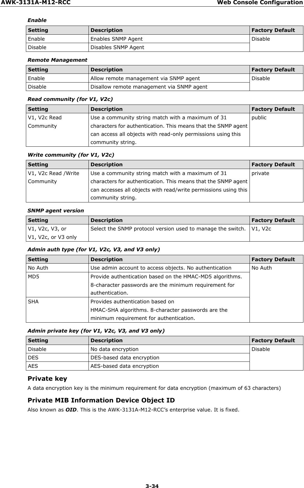
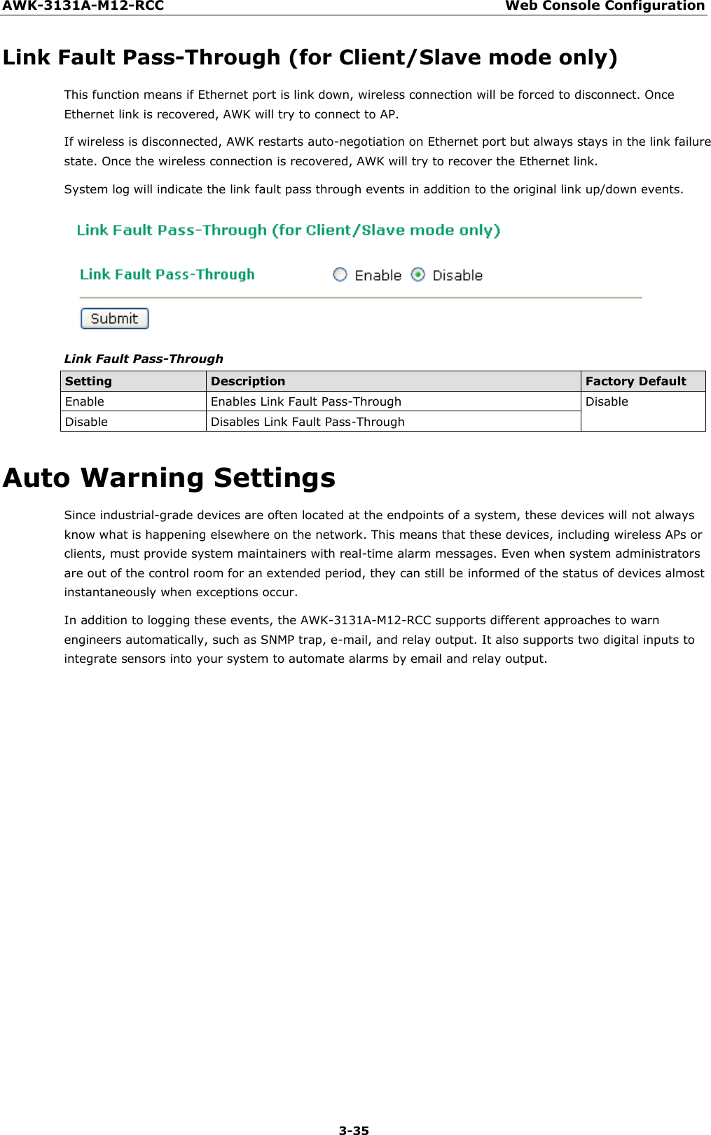
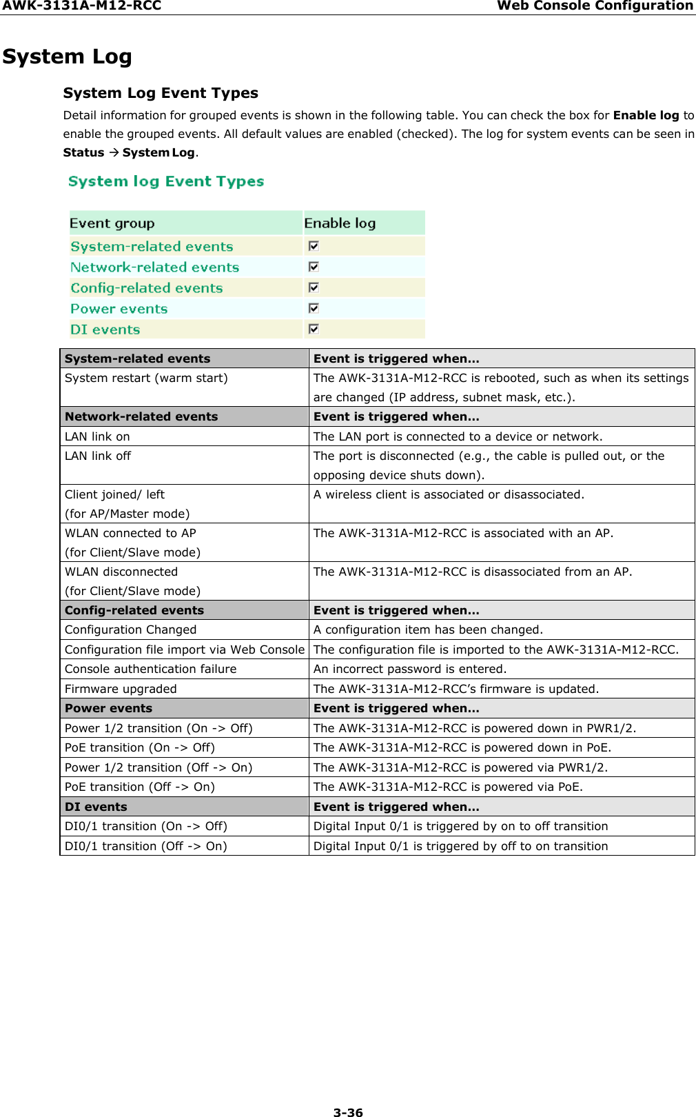
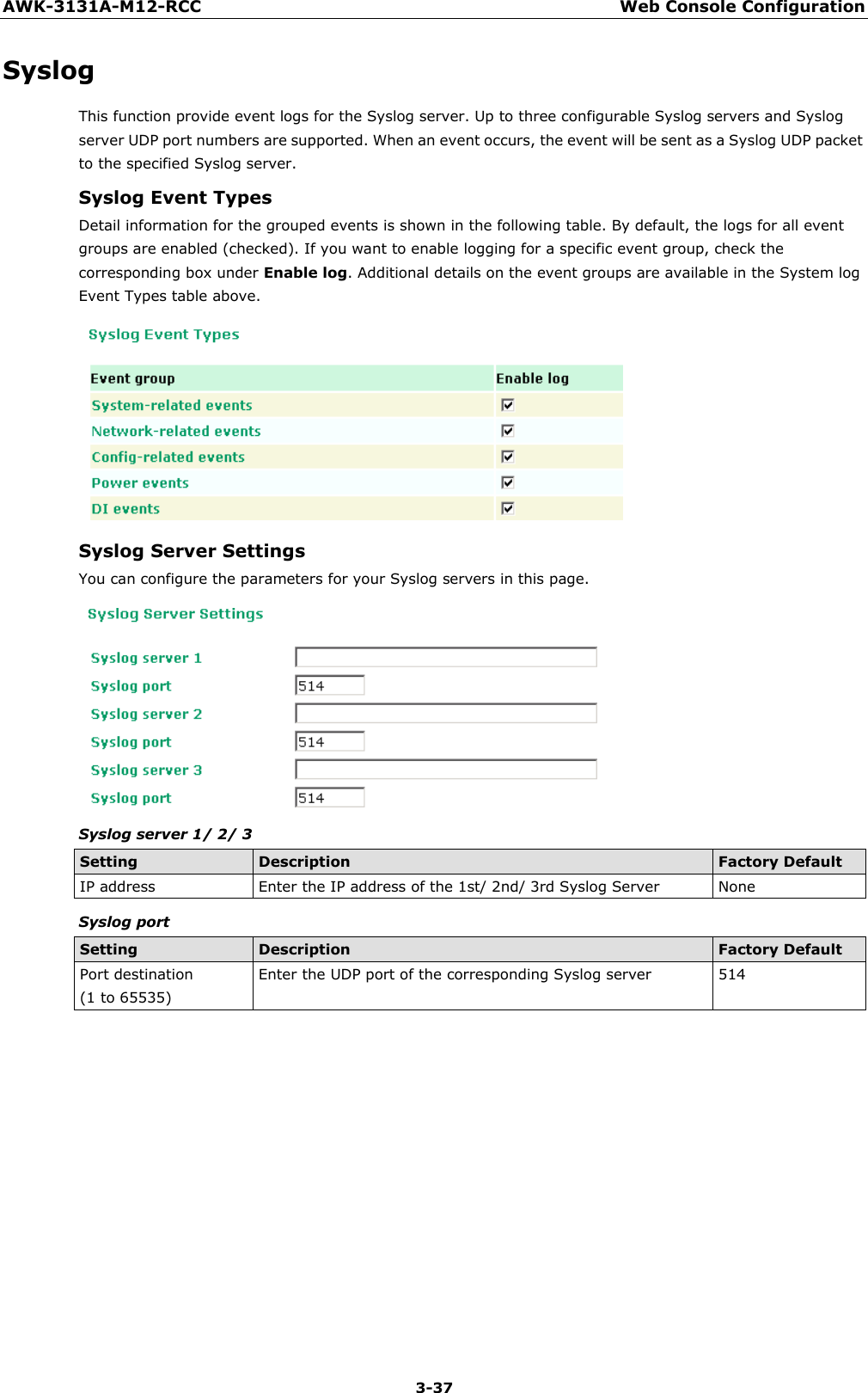
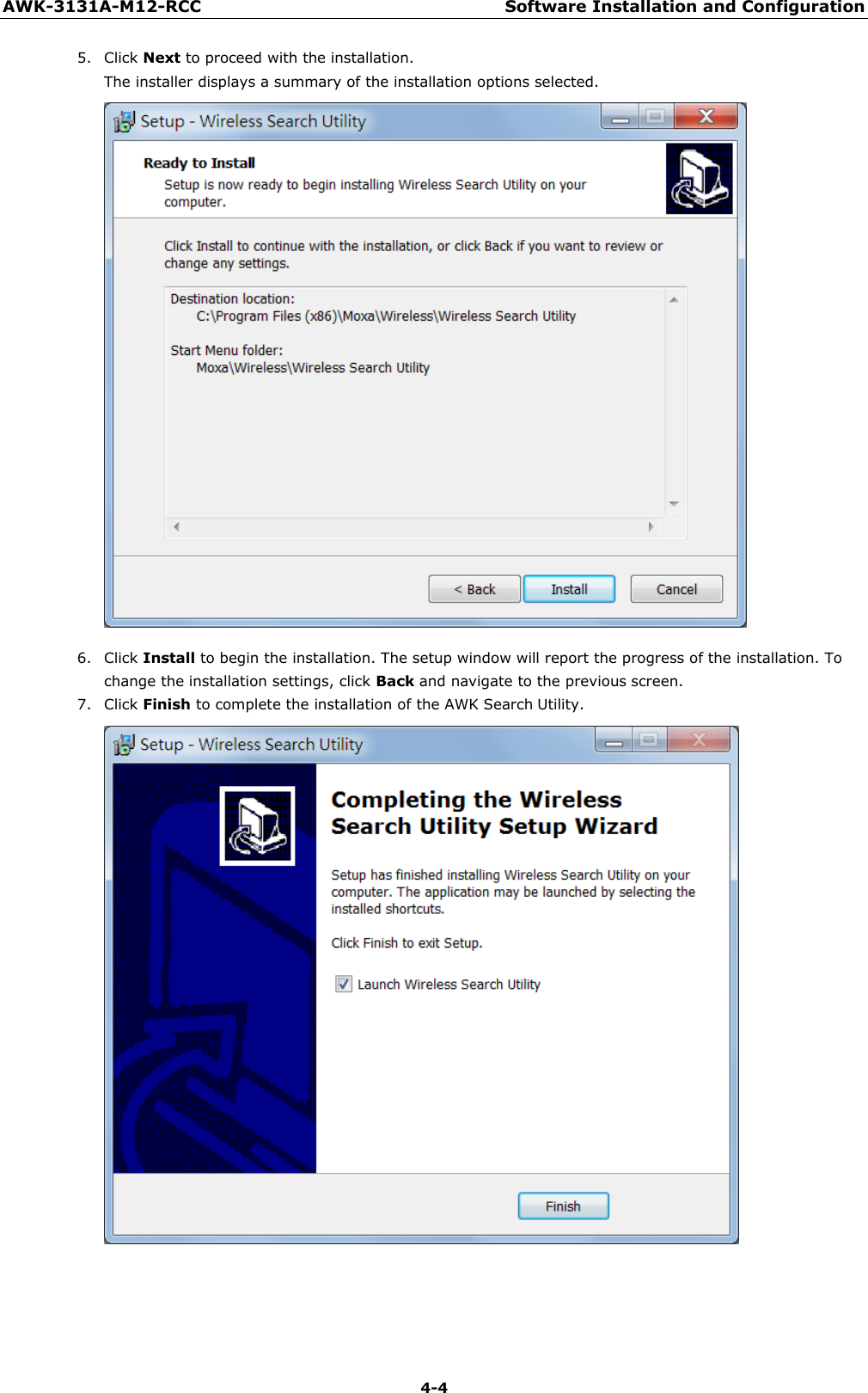
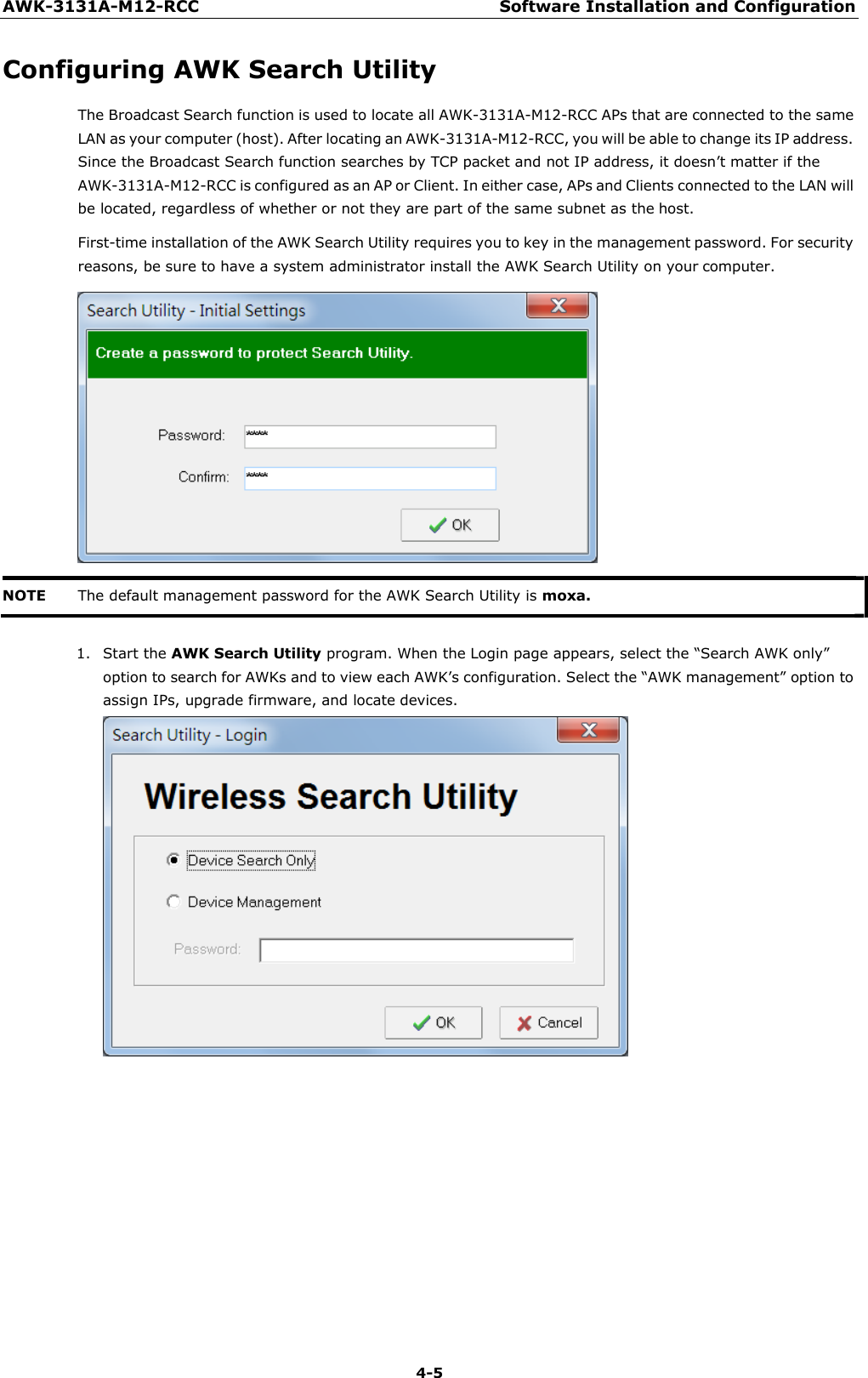
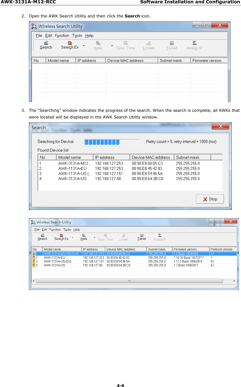
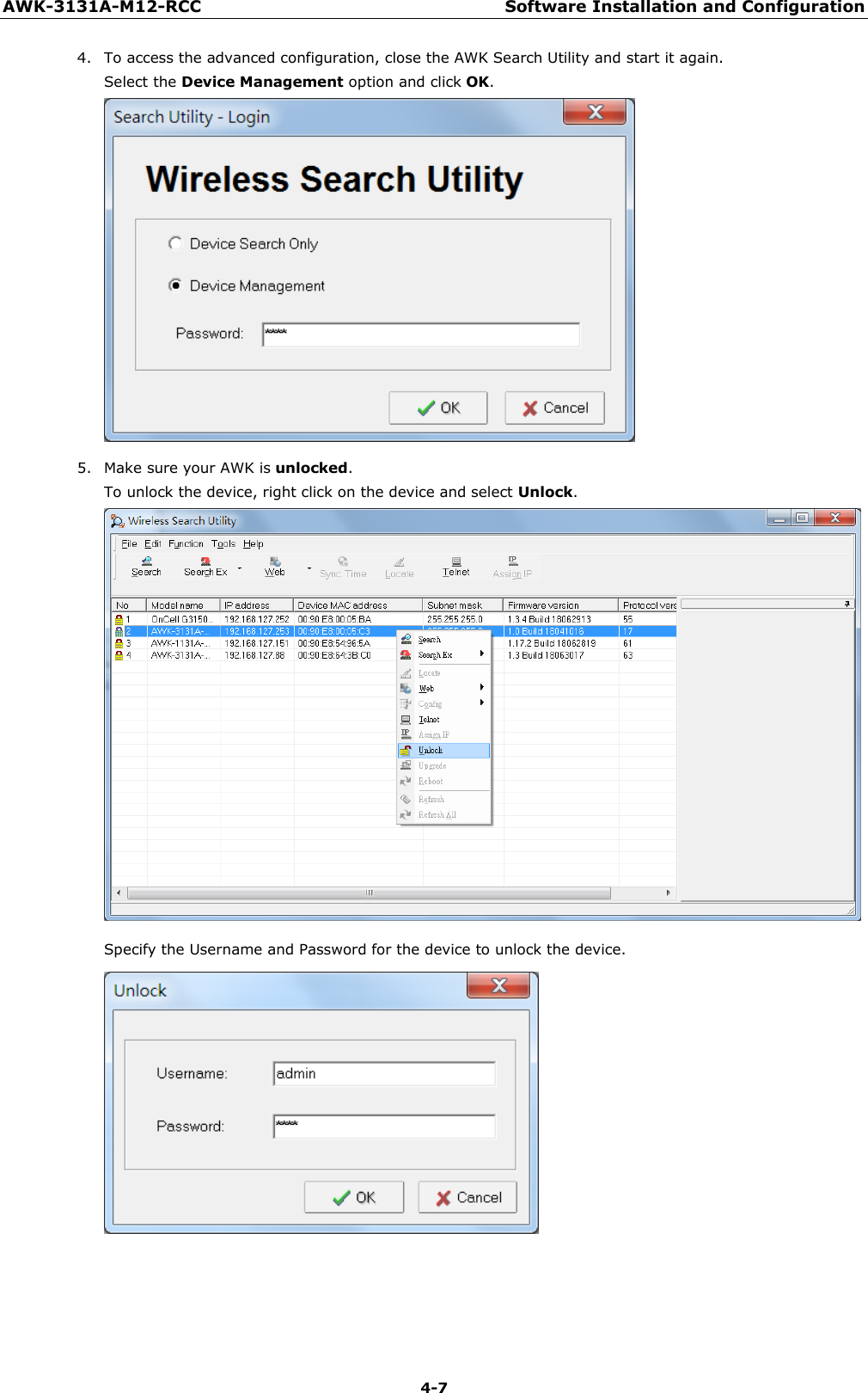
- 8. WAPN008- UserMan_AWK-3131A-M12-RCC_20180820
- 9. WAPN008- UserMan_AWK-3131A-M12-RTG_20180820
- 10. WAPN008- UserMan_AWK-3131A-SSC-RTG_20180820
- 11. WAPN008- UserMan_20180911
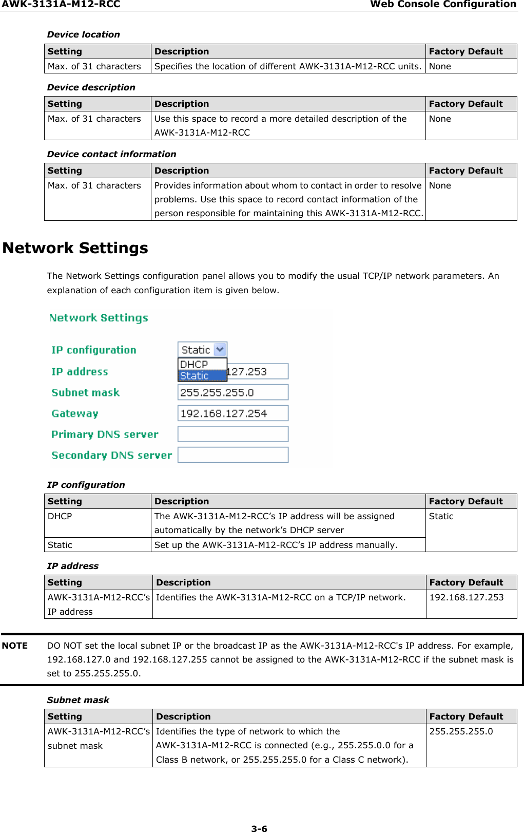
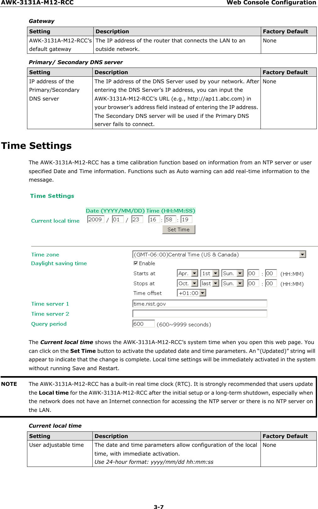
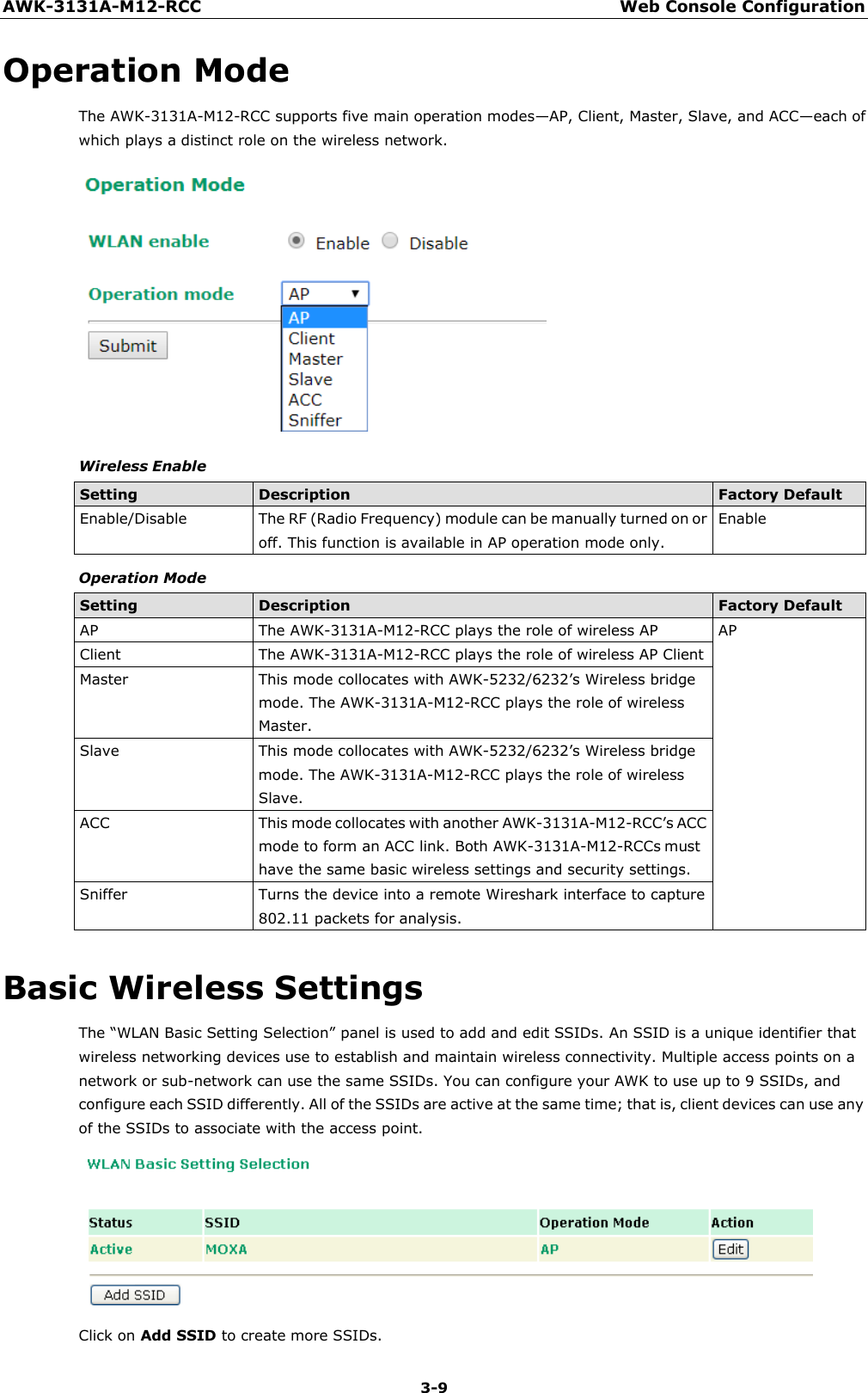
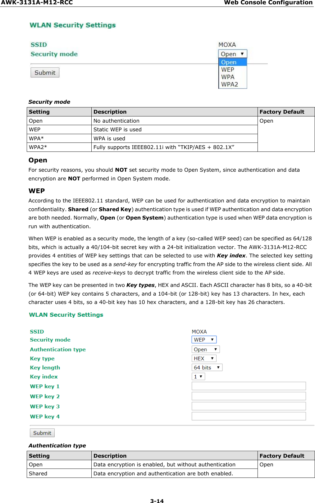
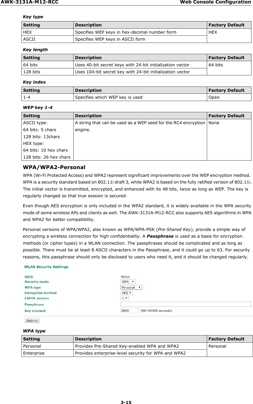
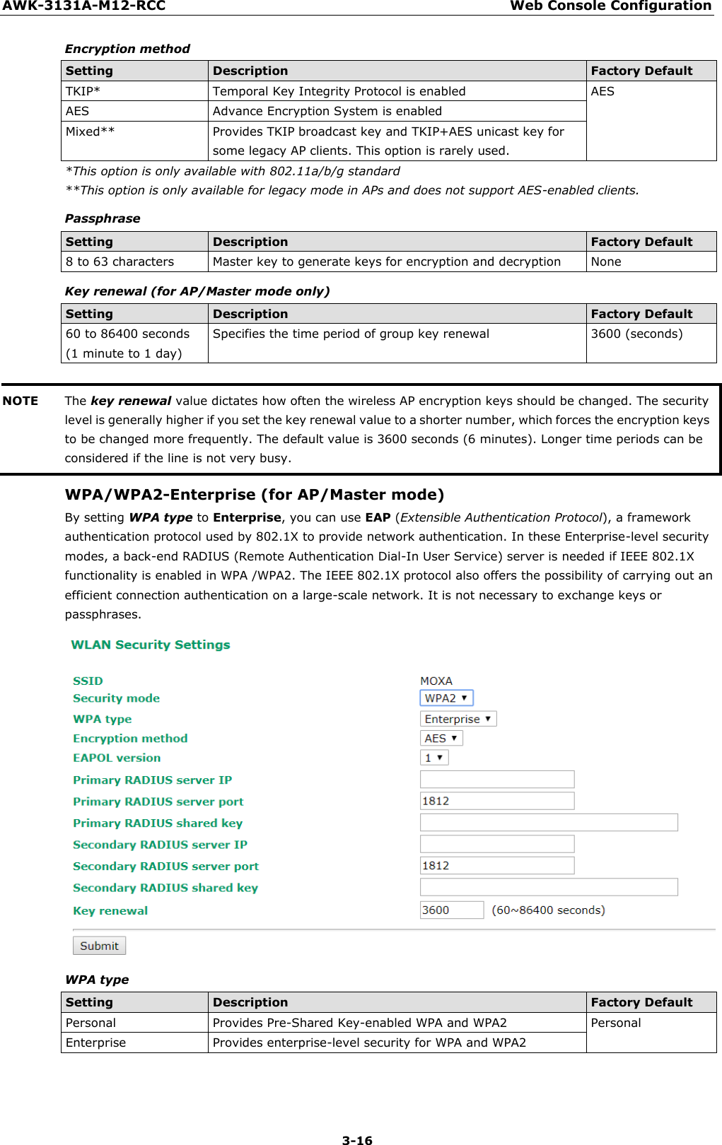
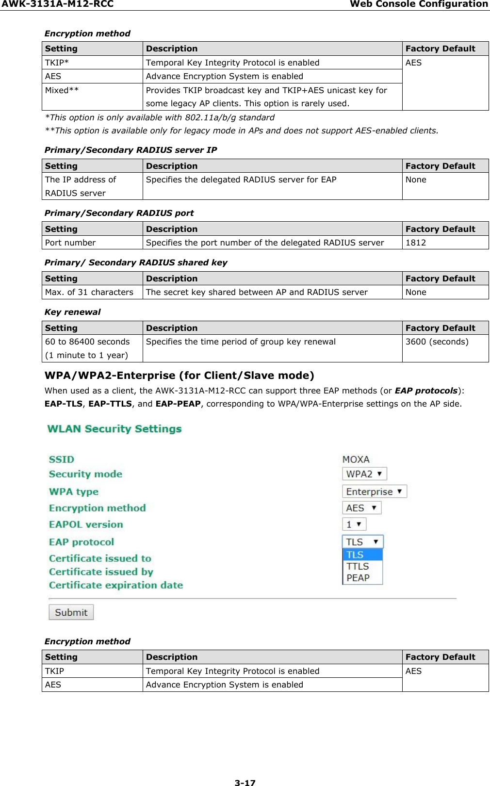
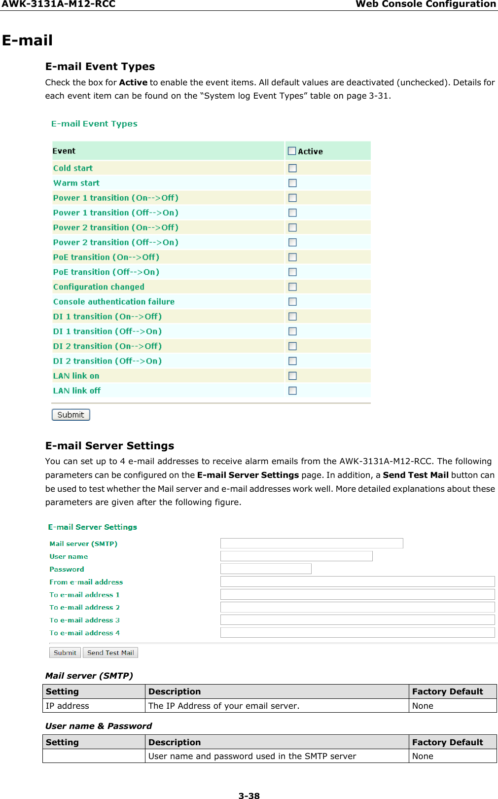
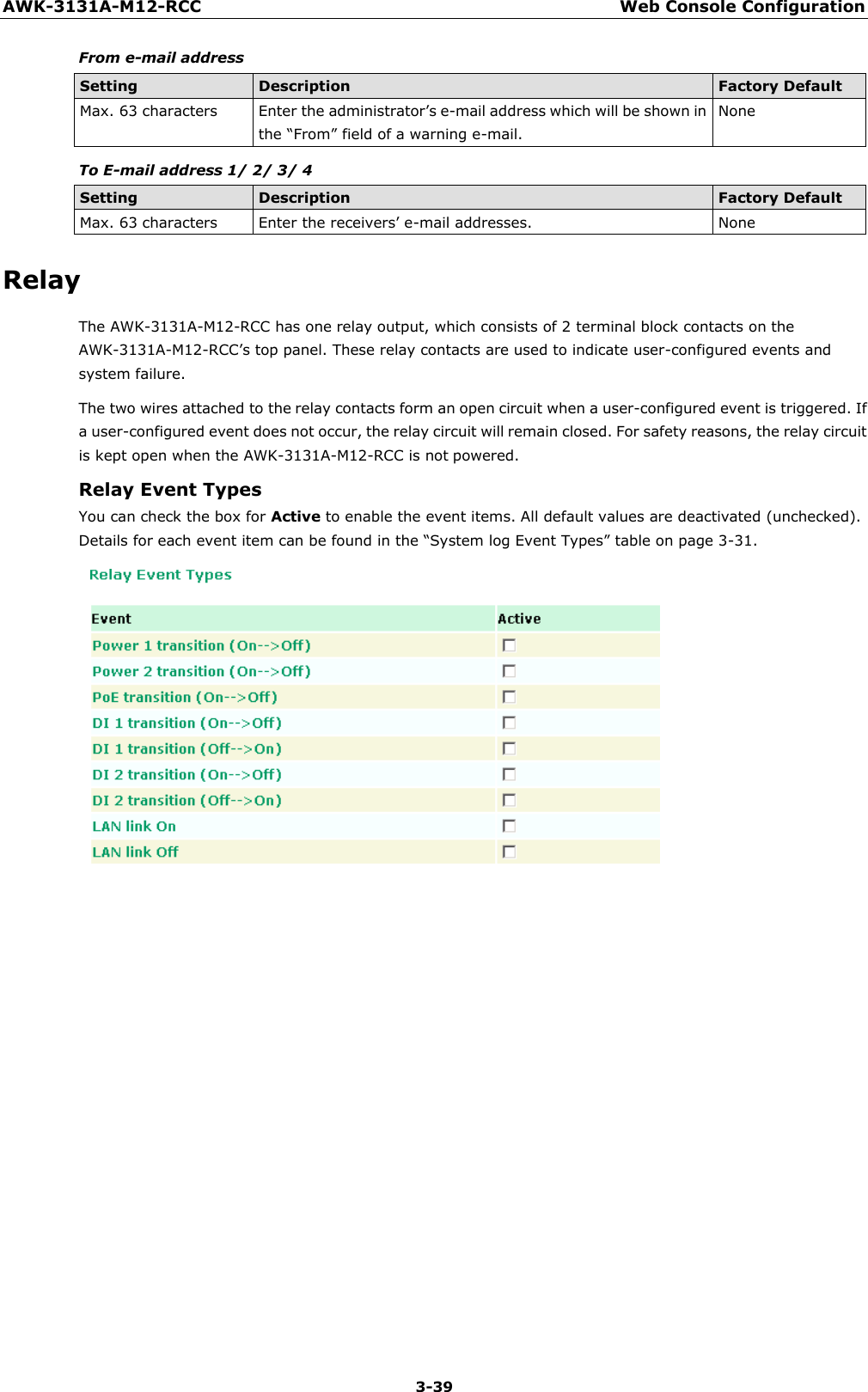
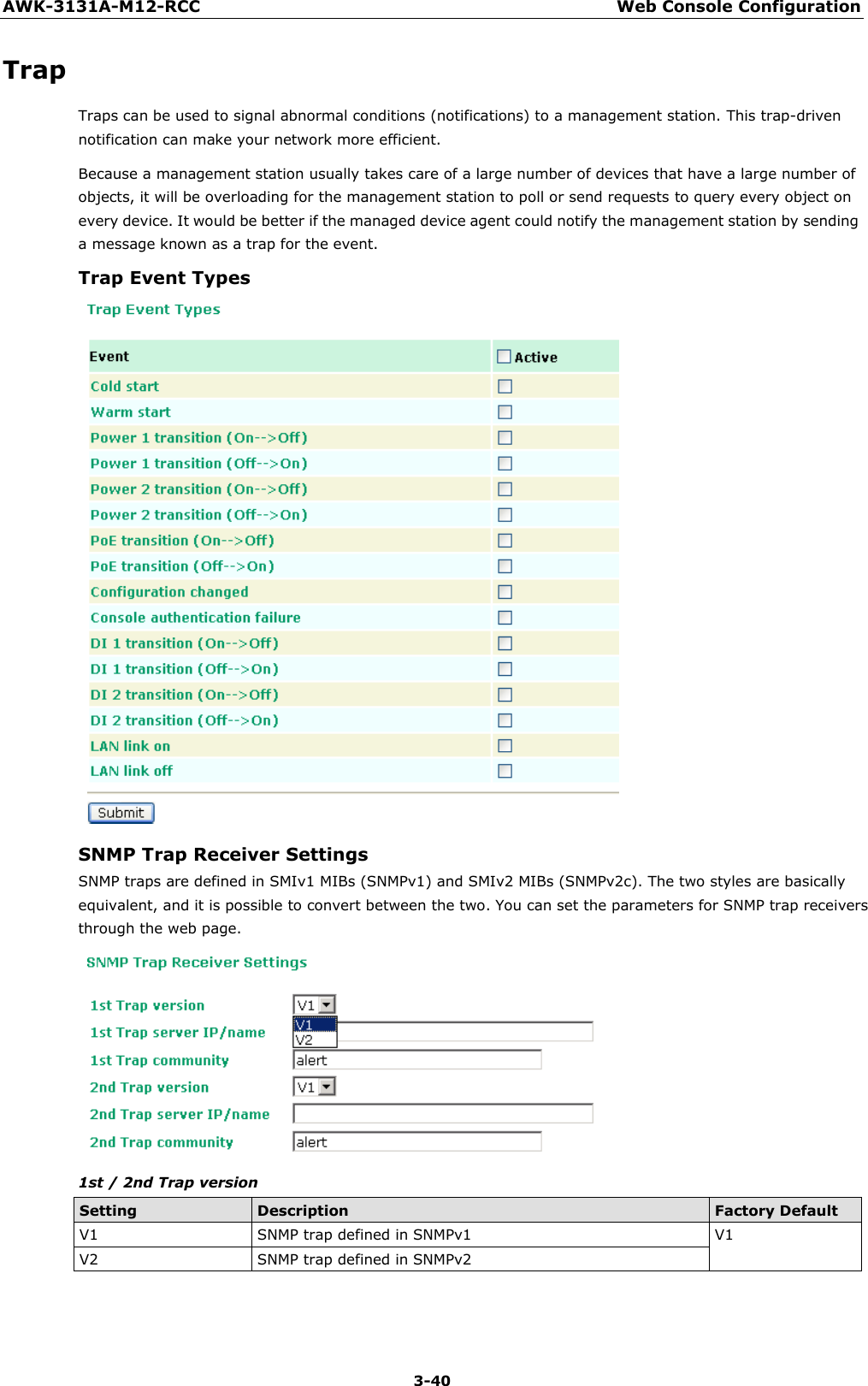
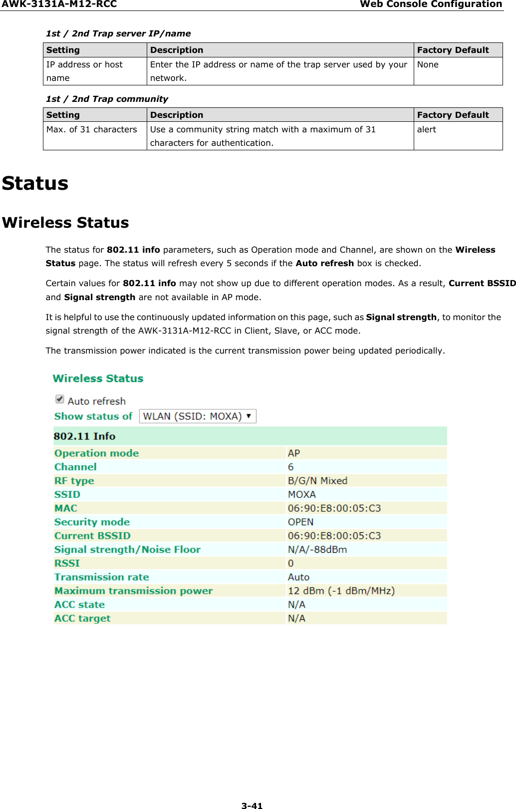
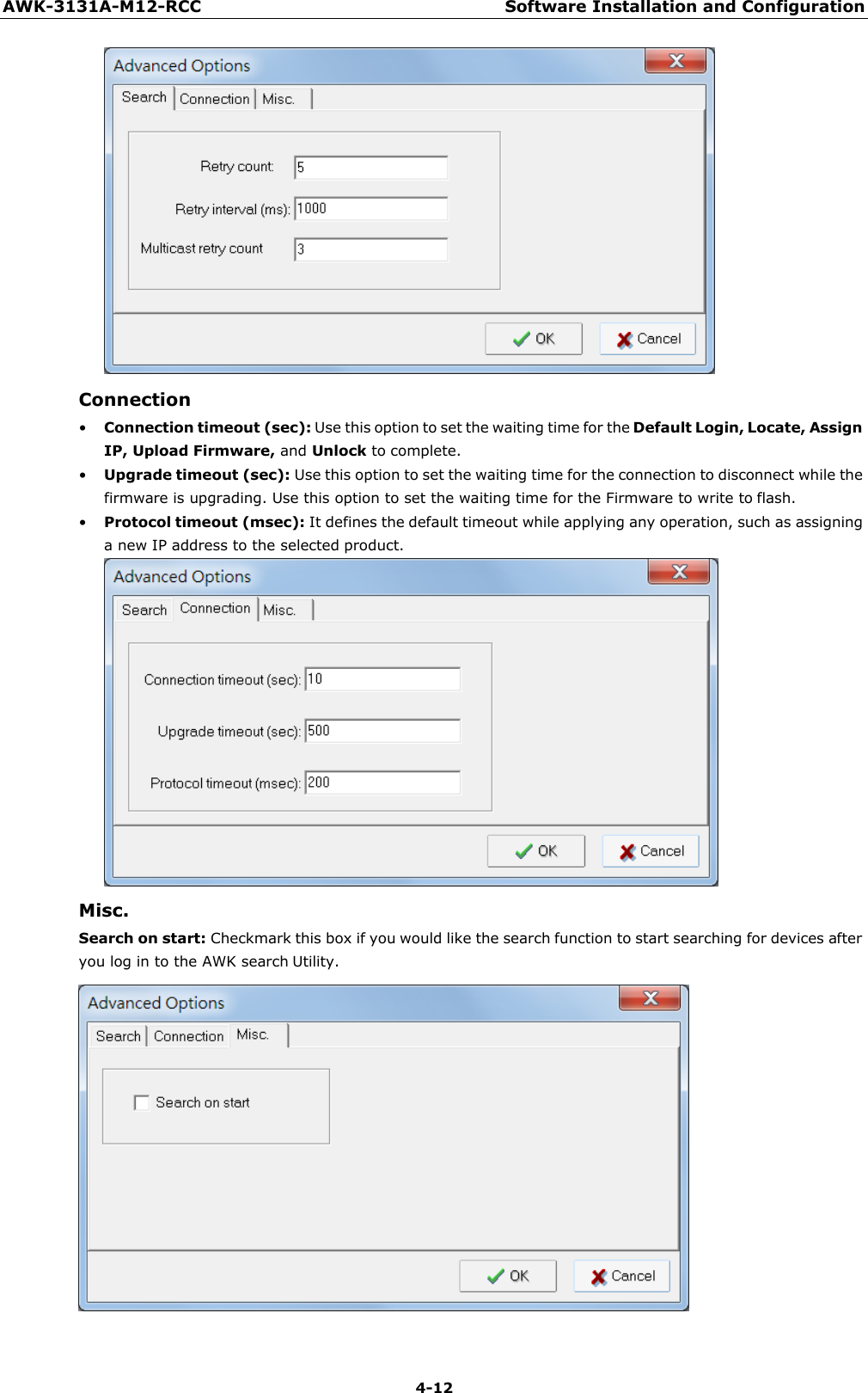
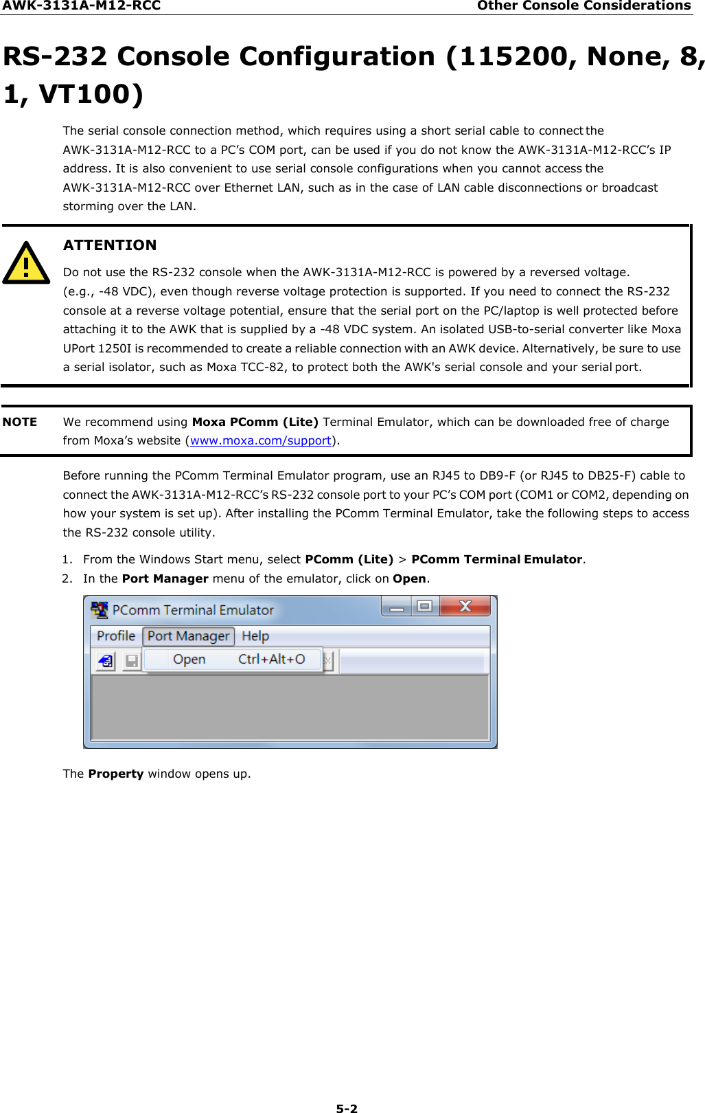
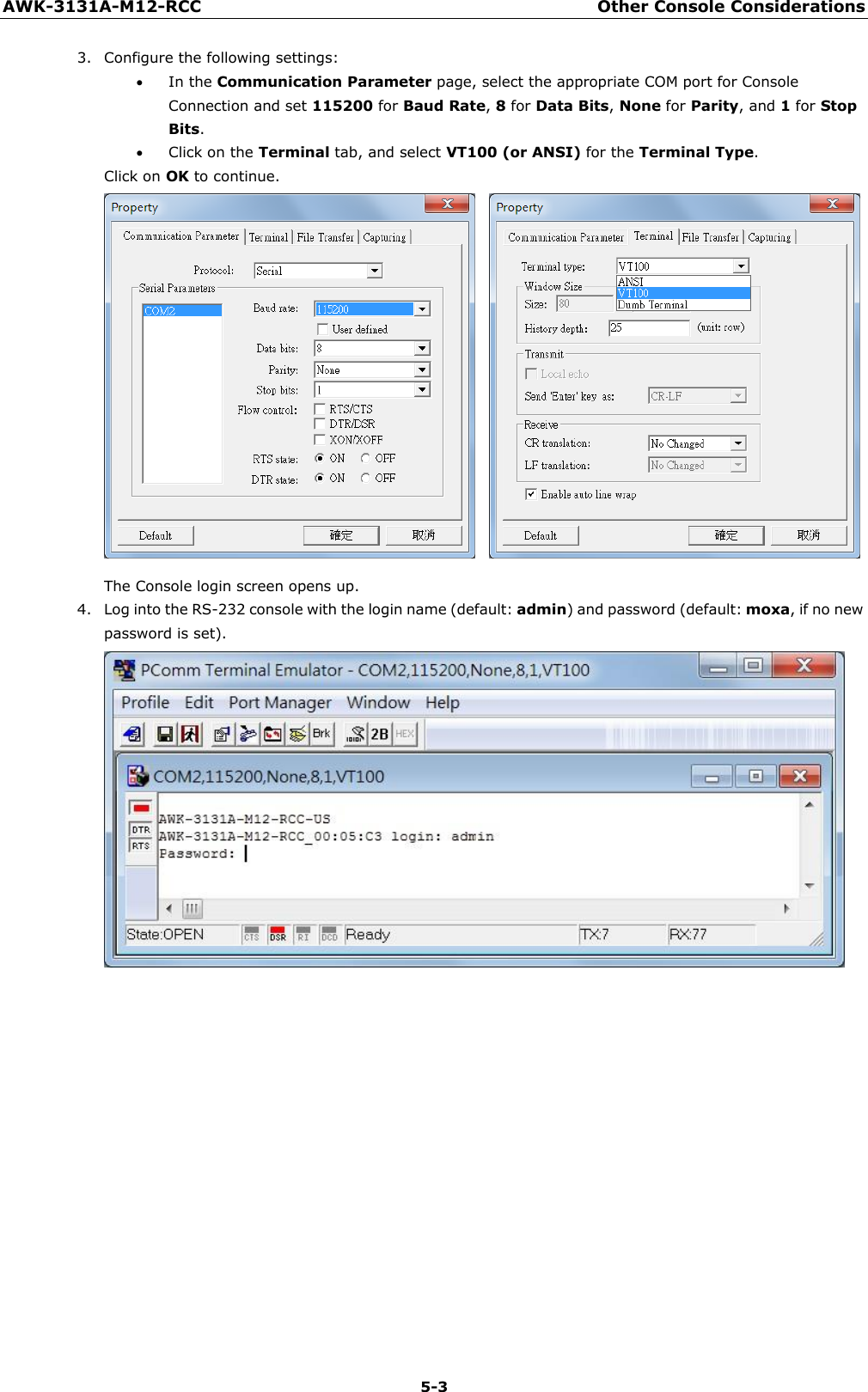
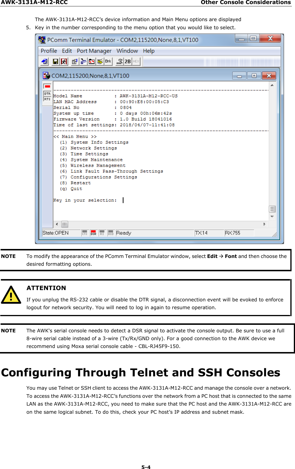
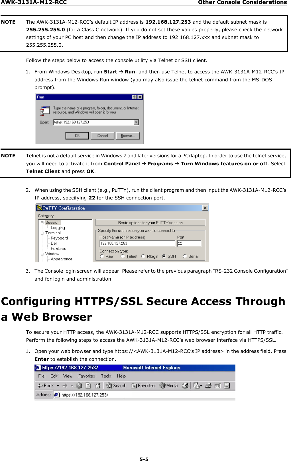
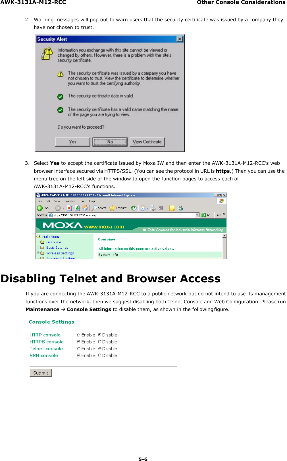
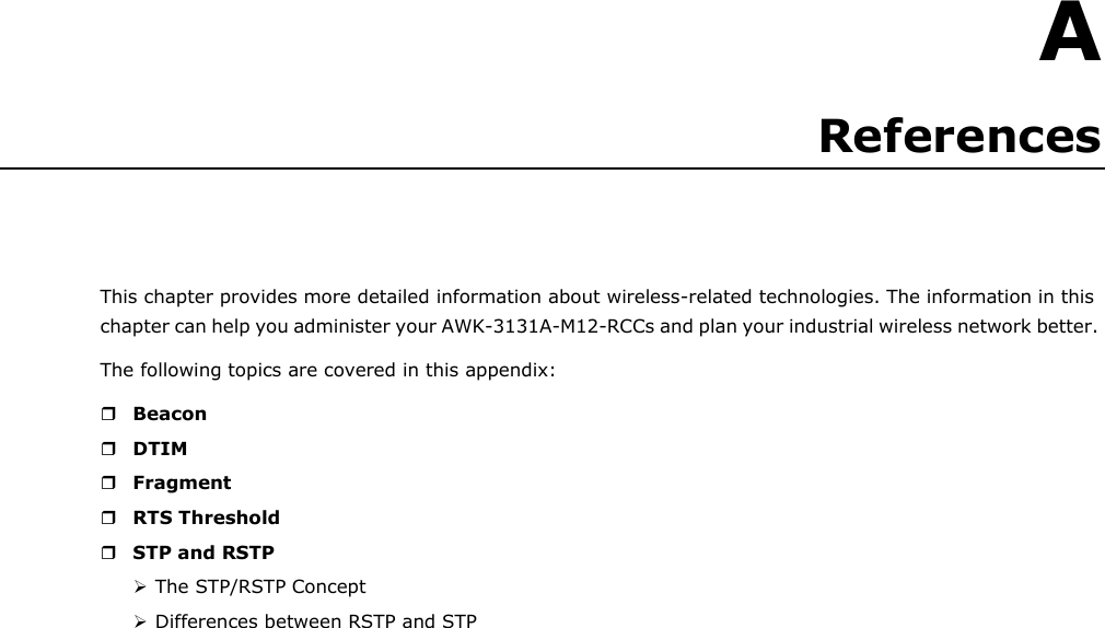
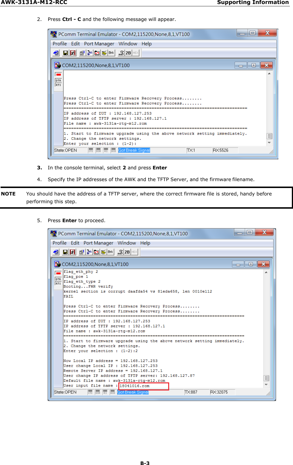
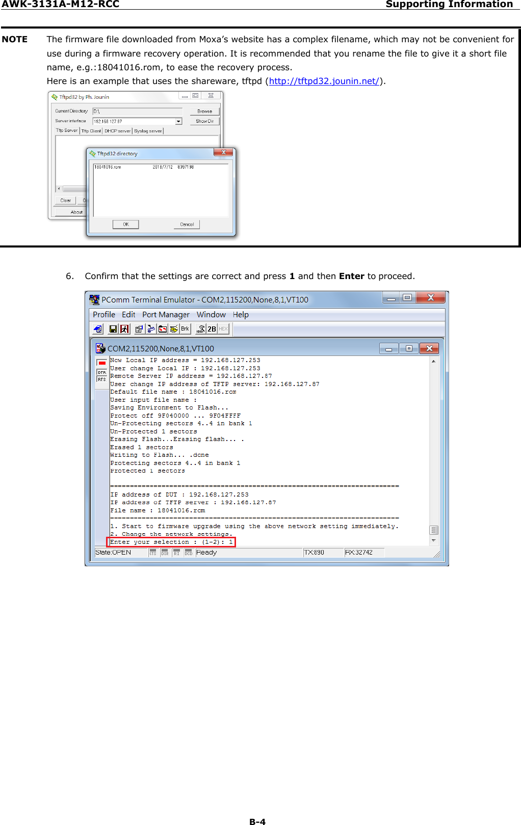
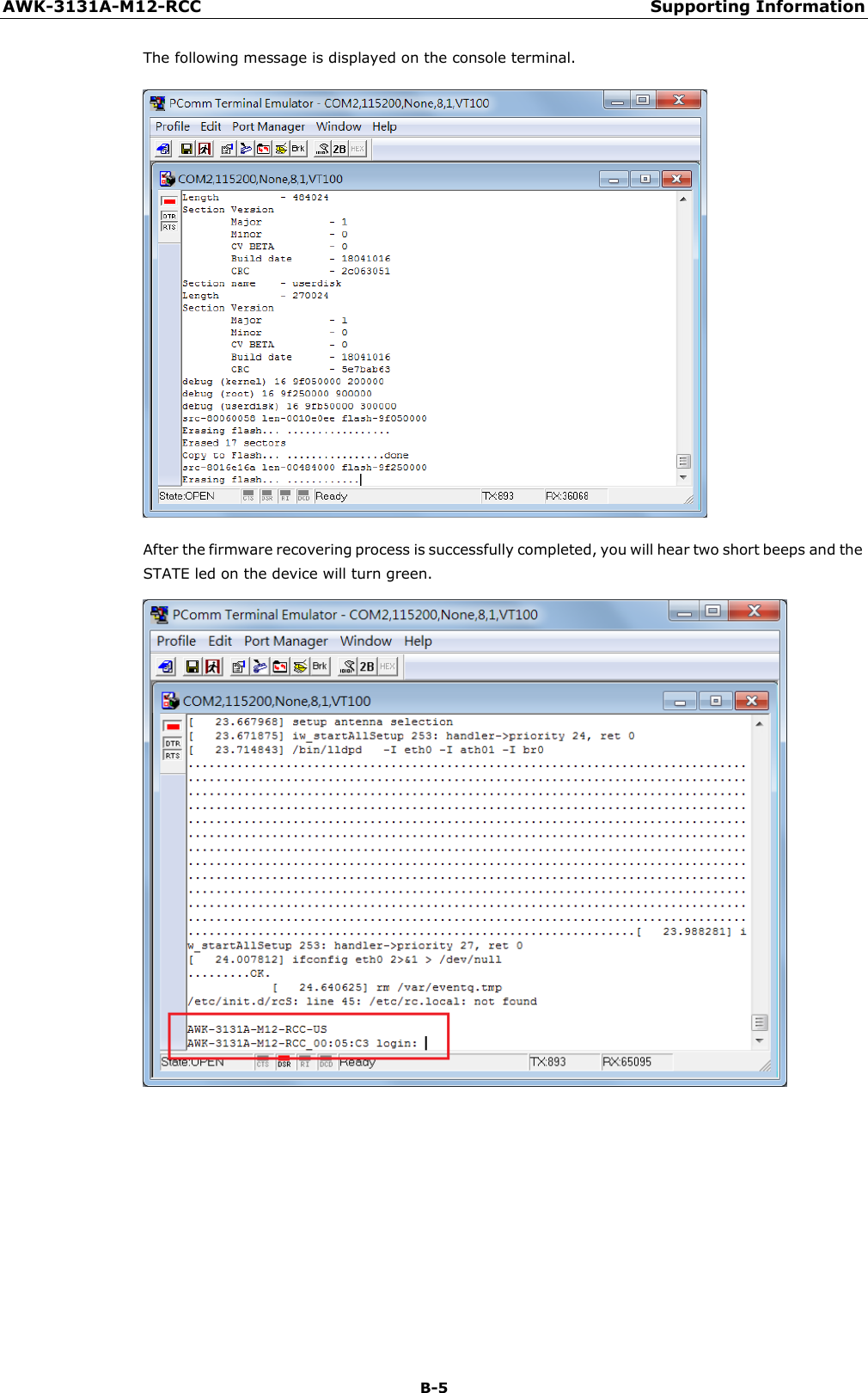
WAPN008- UserMan_AWK-3131A-M12-RCC_20180820