NCR RSD Atlanta 7710GA2 Electronic Pricing Transmitter User Manual Chapter 12
NCR Corporation, RSD - Atlanta Electronic Pricing Transmitter Chapter 12
Contents
- 1. Users Manual Cover
- 2. Users Manual Front
- 3. Users Manual Glossary
- 4. Users Manual Index
- 5. Users Manual Appendix A
- 6. Users Manual Appendix B
- 7. Users Manual Appedix C
- 8. Users Manual Appedix D
- 9. Chapter 1
- 10. Chapter 2
- 11. Chapter 3
- 12. Chapter 4
- 13. Chapter 5
- 14. Chapter 6
- 15. Chapter 7
- 16. Chapter 8
- 17. Chapter 9
- 18. Chapter 10
- 19. Chapter 11
- 20. Chapter 12
- 21. Chapter 13
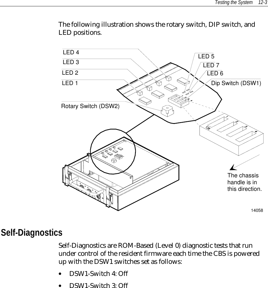
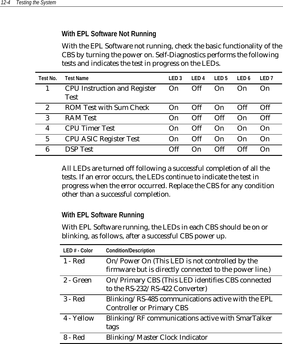
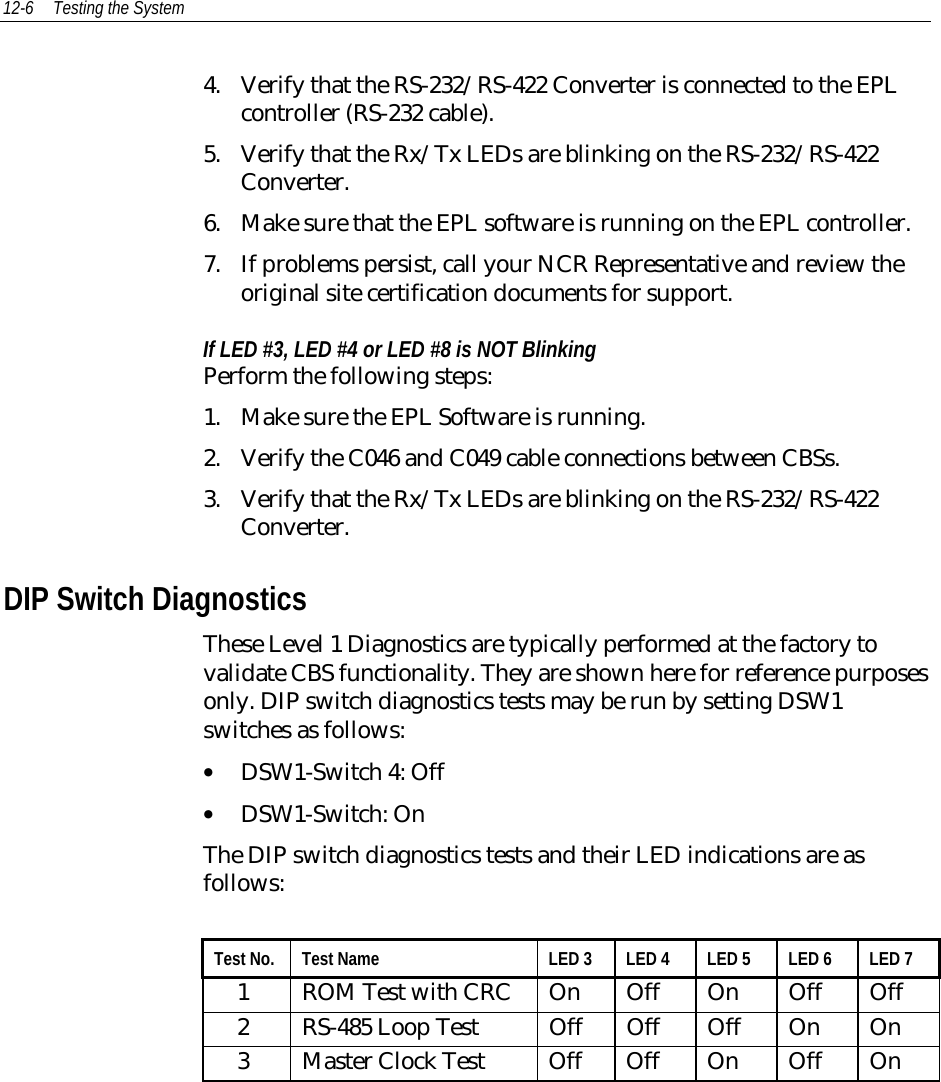
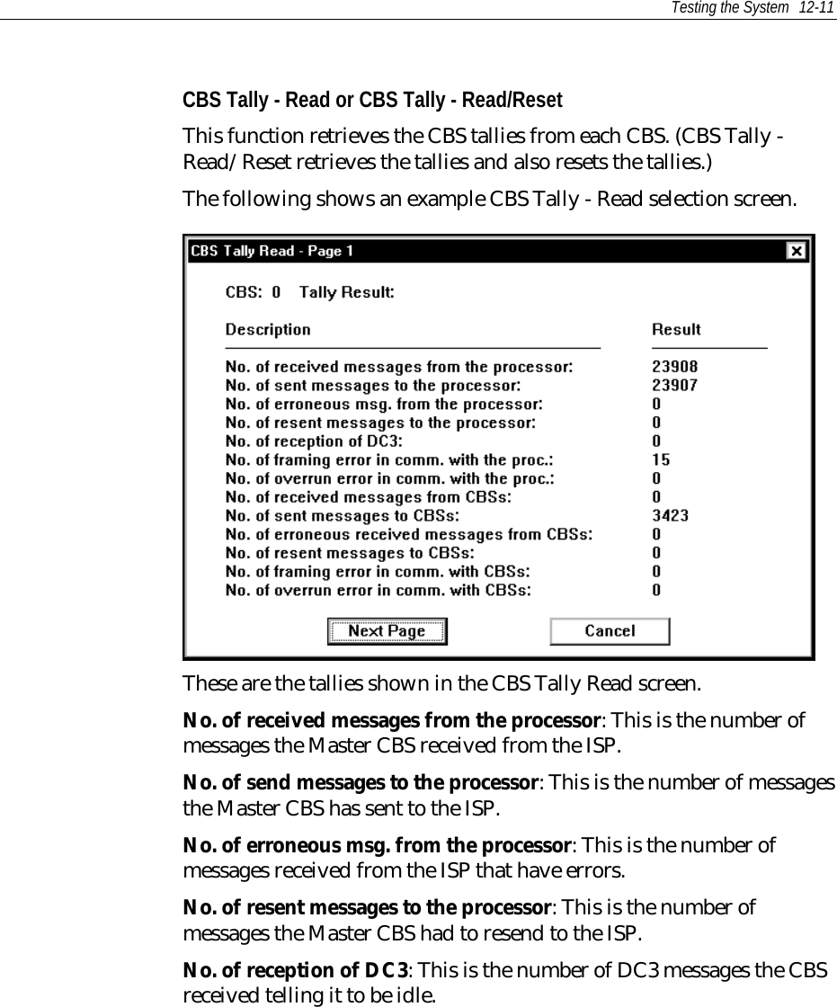
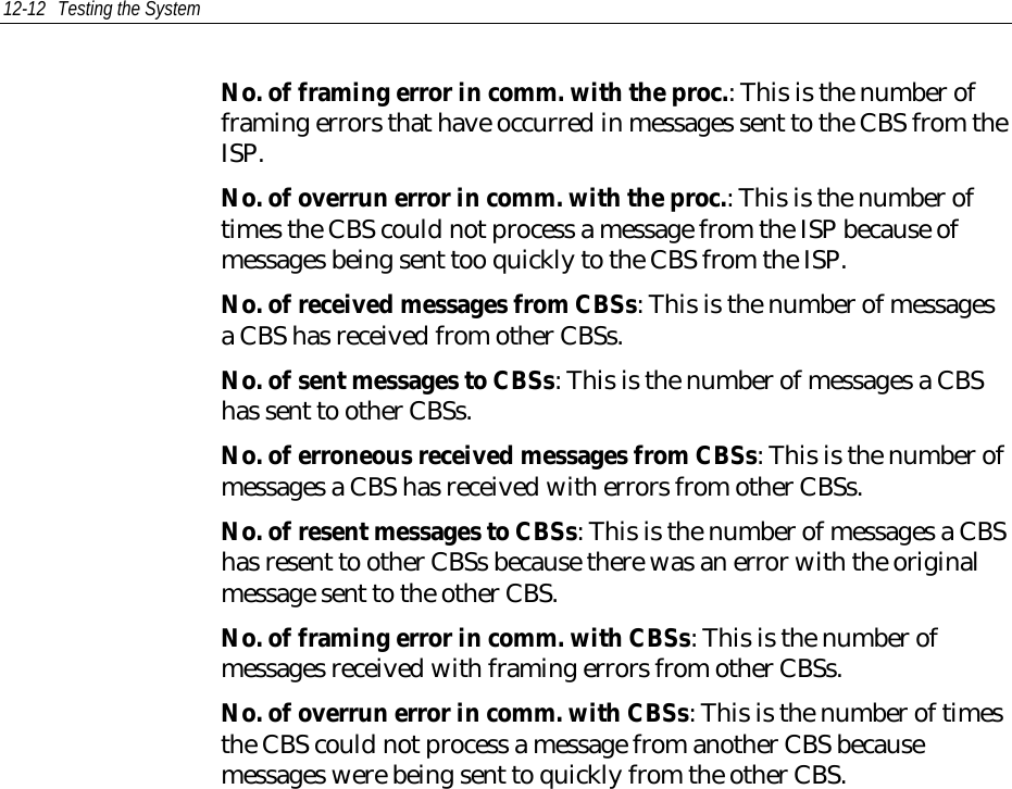
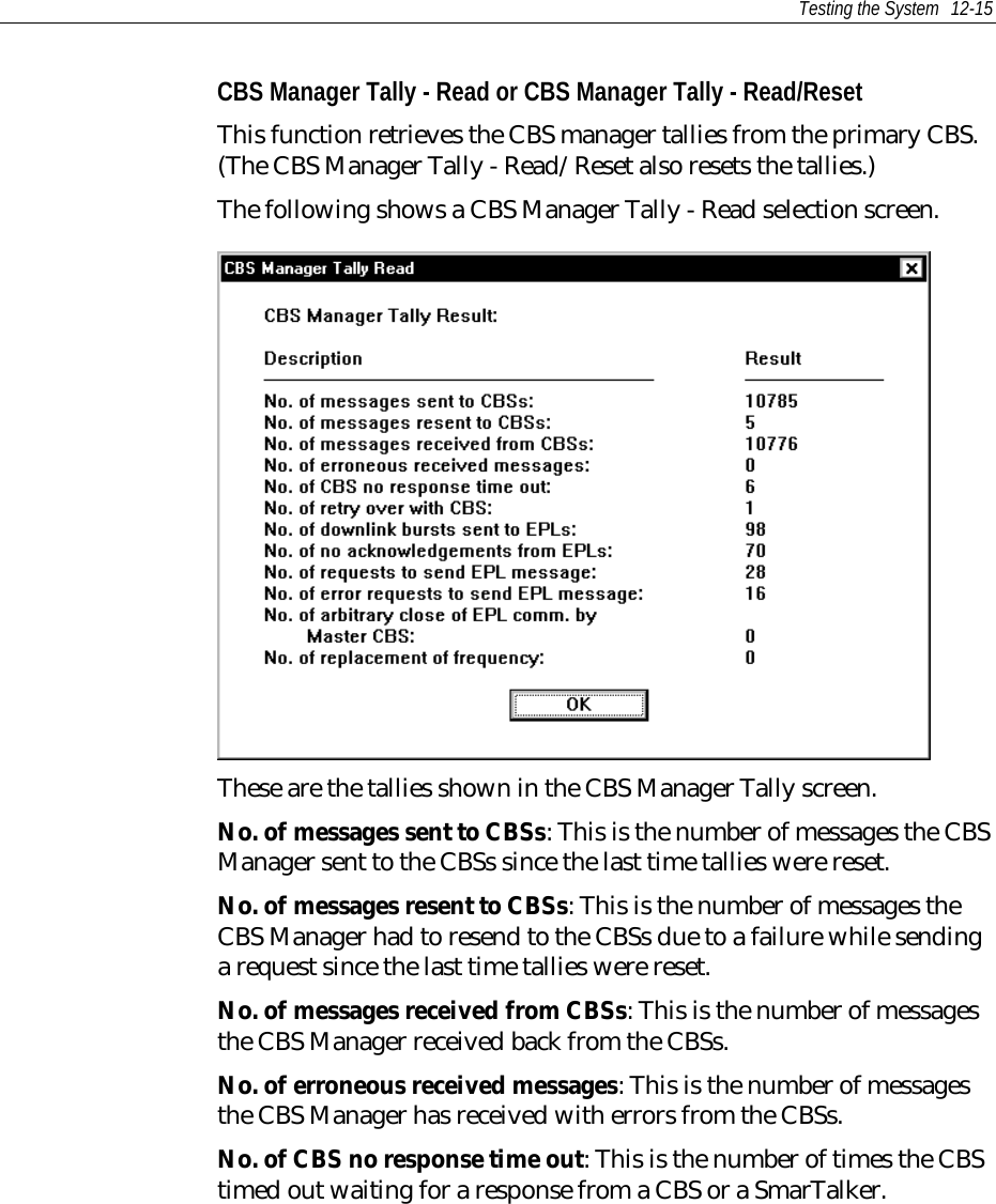
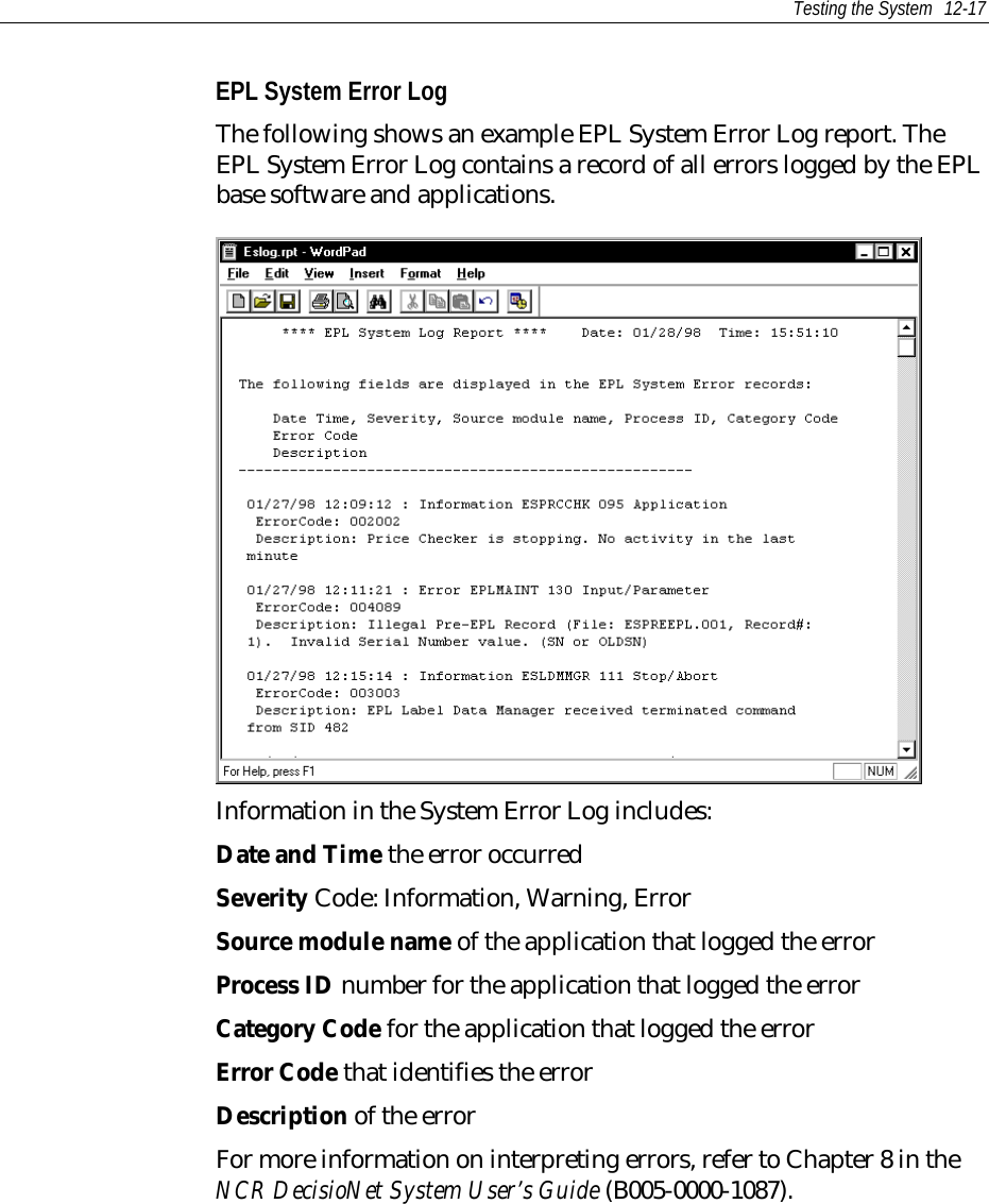
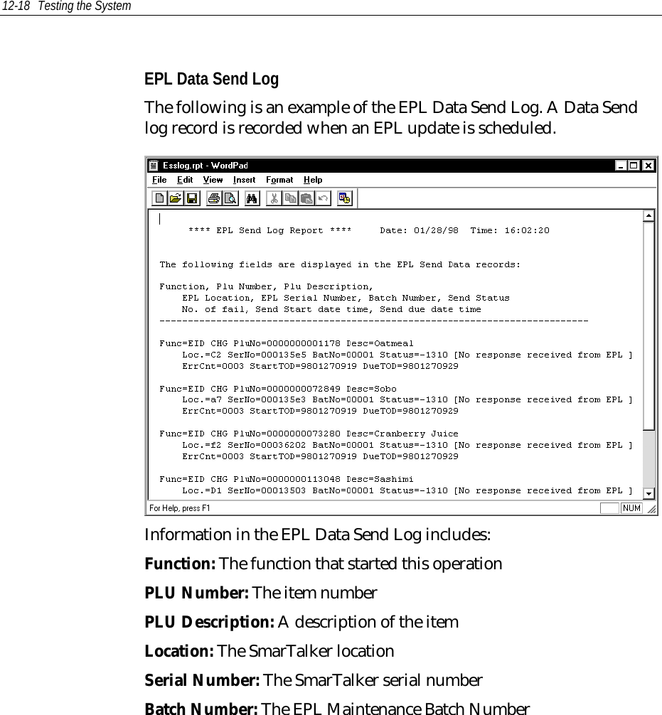
Chapter 12
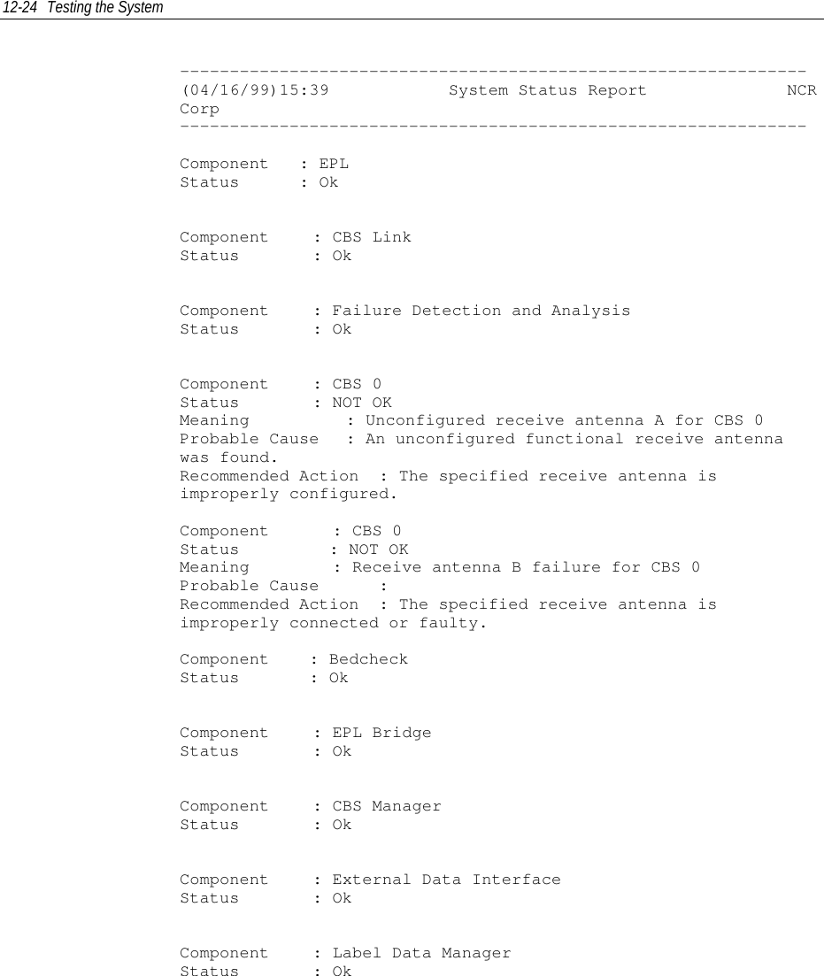
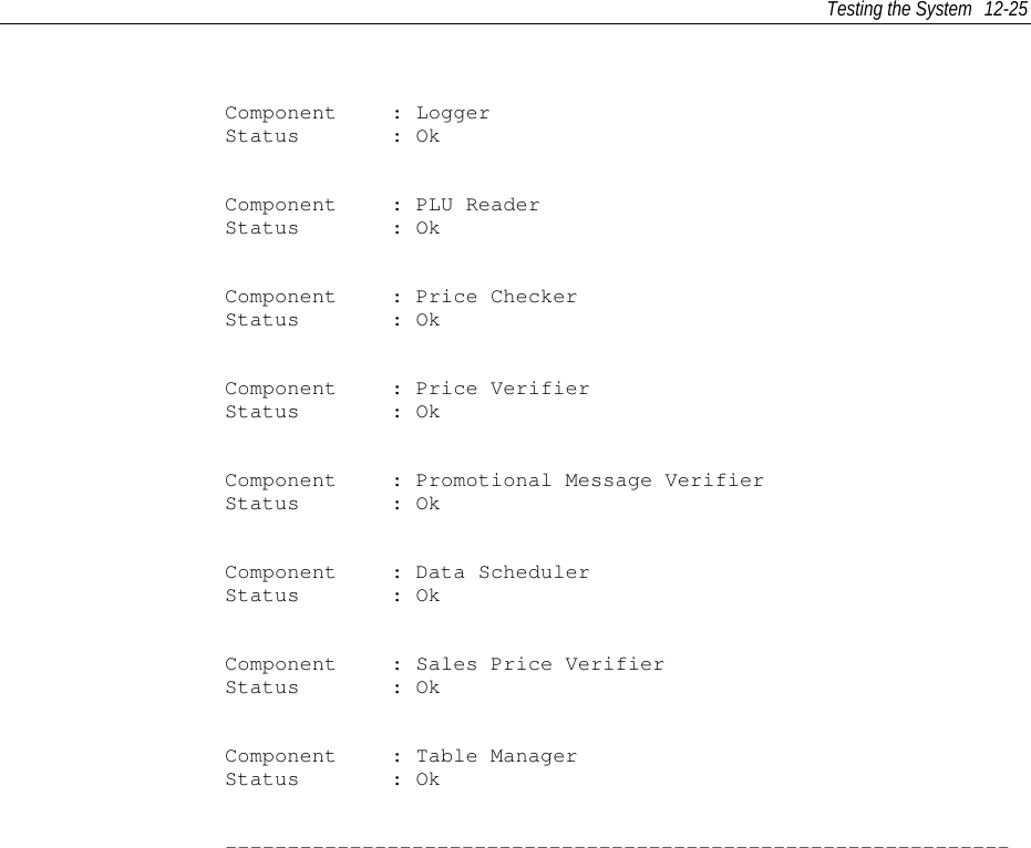
![Testing the System 12-23Running FDA from a System Prompt When started with other EPL Applications, FDA runs continuouslyand logs errors as they occur. Use the following procedures to runFDA in single-pass mode. The results of the report are sent to theconsole and placed in the EPL System Error Log. Use the -f commandline option to save the report to a file for viewing and printing.1. At a DOS or UNIX prompt, enter esfda to start FDA in single-passmode.2. Review the information output to the console screen, the EPLSystem Error Log and Windows NT Event Log (if testing onWindows NT system).The syntax and options for esfda are as follows:esfda [-r][-x][-y][-f<filename>]-r Report on software and hardware components-x Report only on the hardware components-y Report only on the software components-f<x> Save report in the file specified by <x>. If a path is notspecified, the file is placed in the epl/data/statusdirectory.Example:• Run a hardware and software test and place the report in a filenamed fdatest.esfda -rf fdatestThe following is our report created for the example above.](https://usermanual.wiki/NCR-RSD-Atlanta/7710GA2.Chapter-12/User-Guide-47907-Page-23.png)