NCR RSD Atlanta 7710GA2 Electronic Pricing Transmitter User Manual Chapter 4
NCR Corporation, RSD - Atlanta Electronic Pricing Transmitter Chapter 4
Contents
- 1. Users Manual Cover
- 2. Users Manual Front
- 3. Users Manual Glossary
- 4. Users Manual Index
- 5. Users Manual Appendix A
- 6. Users Manual Appendix B
- 7. Users Manual Appedix C
- 8. Users Manual Appedix D
- 9. Chapter 1
- 10. Chapter 2
- 11. Chapter 3
- 12. Chapter 4
- 13. Chapter 5
- 14. Chapter 6
- 15. Chapter 7
- 16. Chapter 8
- 17. Chapter 9
- 18. Chapter 10
- 19. Chapter 11
- 20. Chapter 12
- 21. Chapter 13
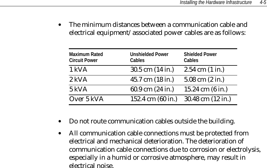
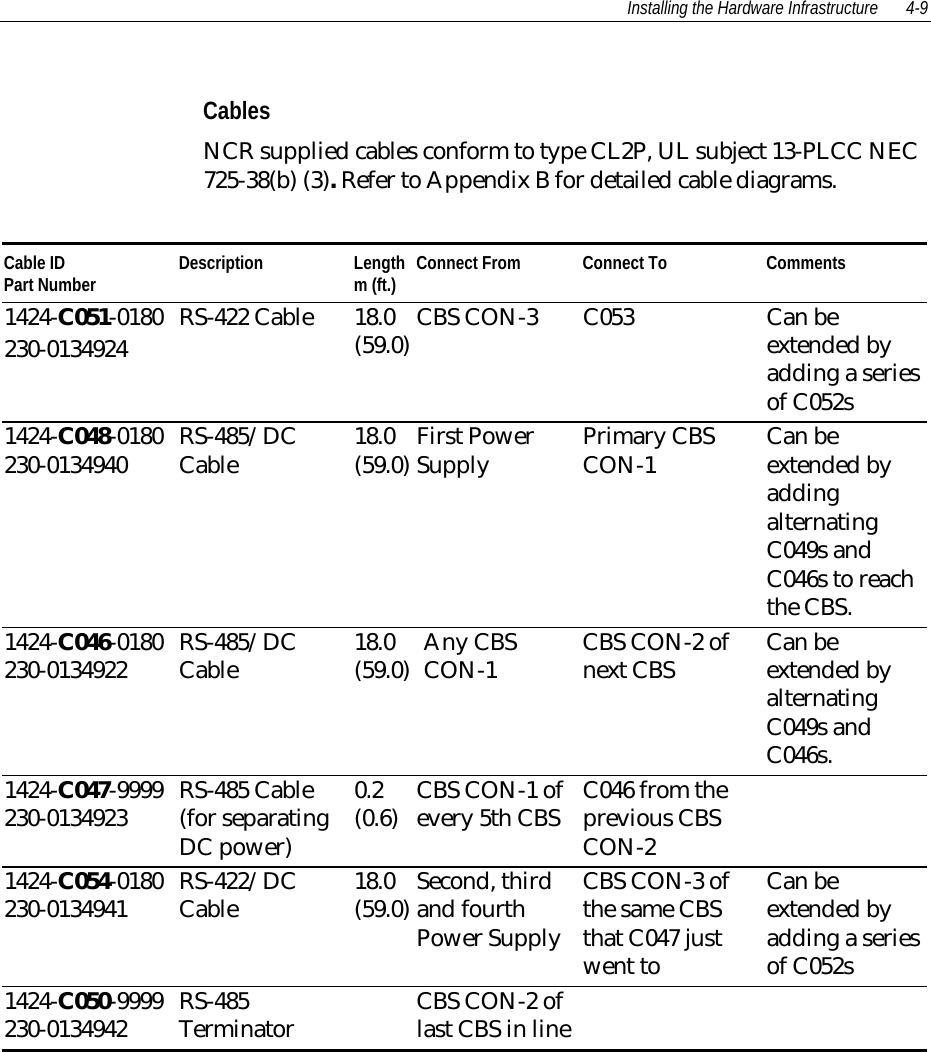
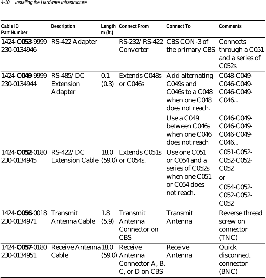
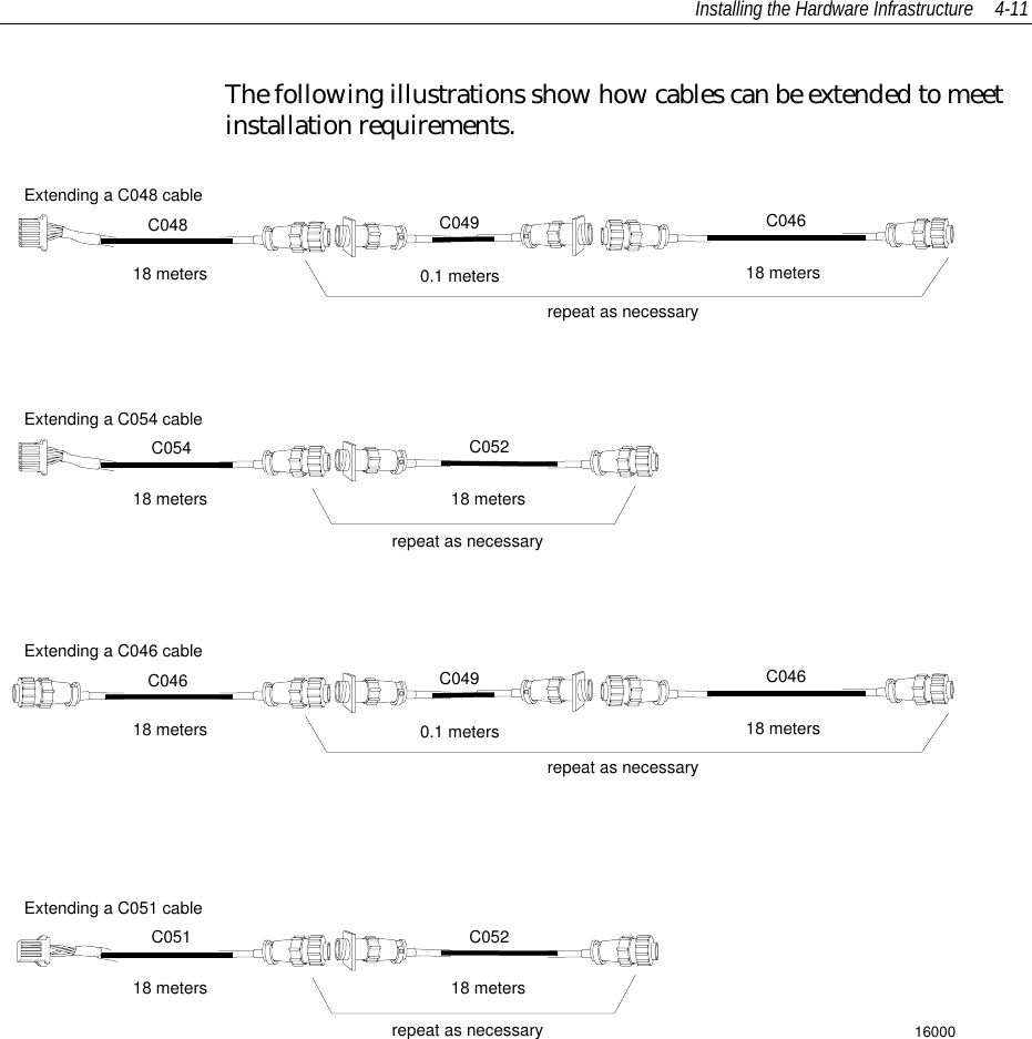
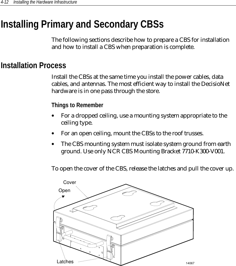
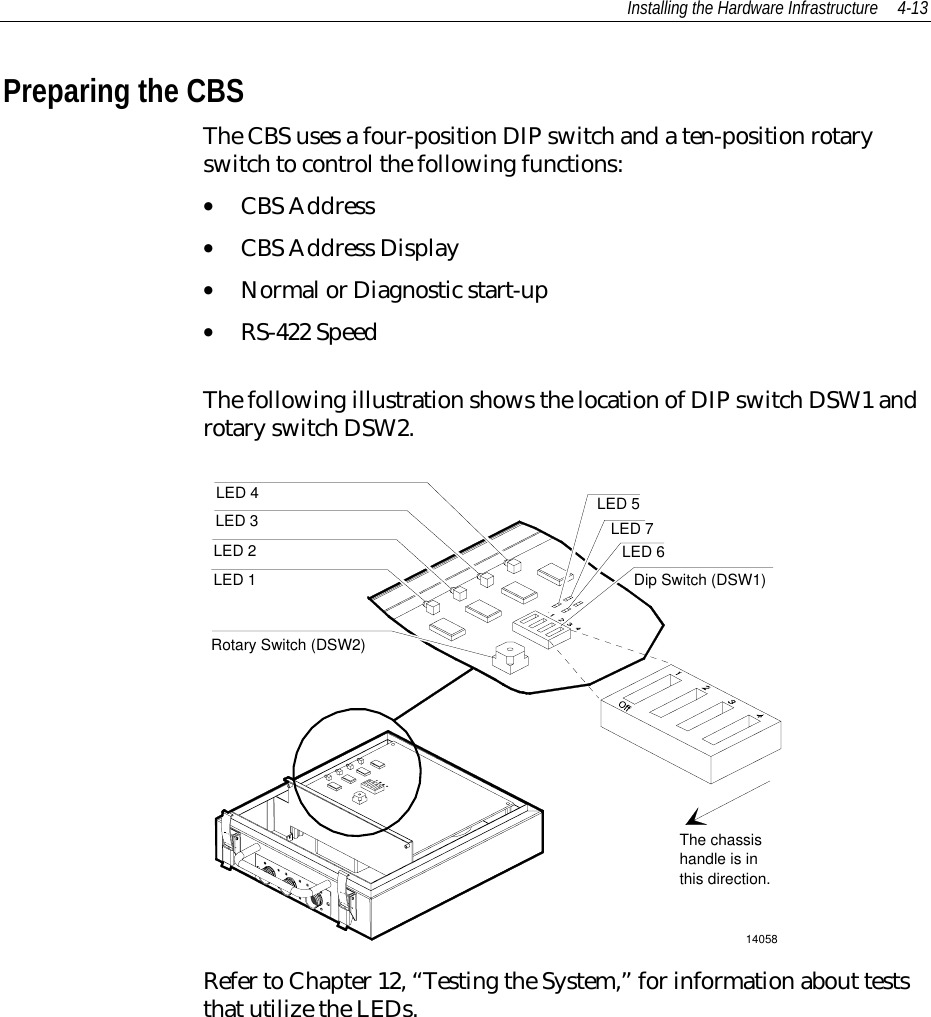
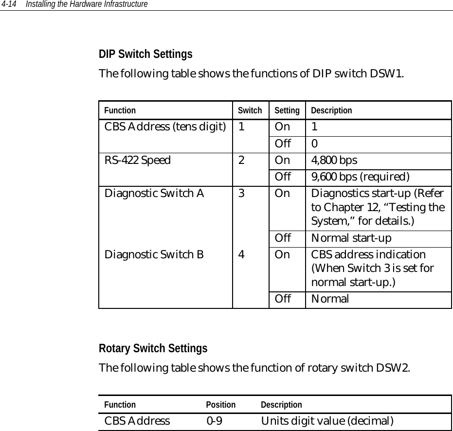
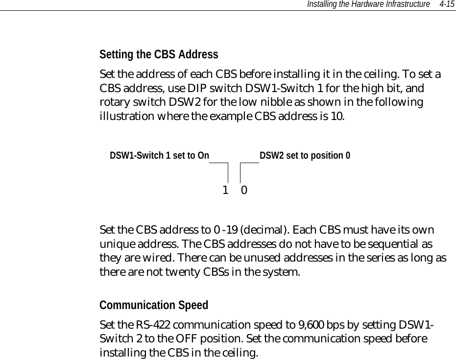
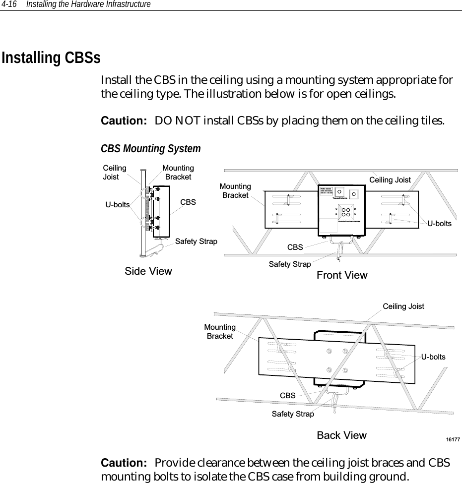
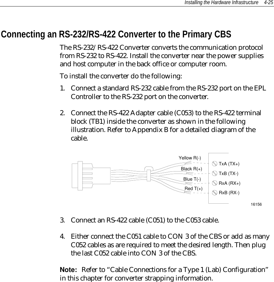
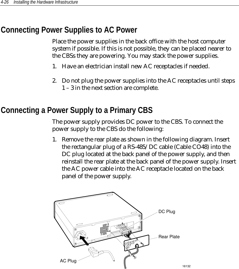
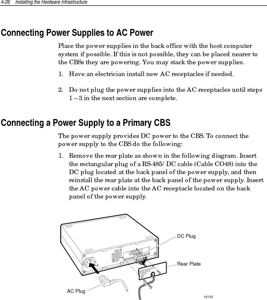
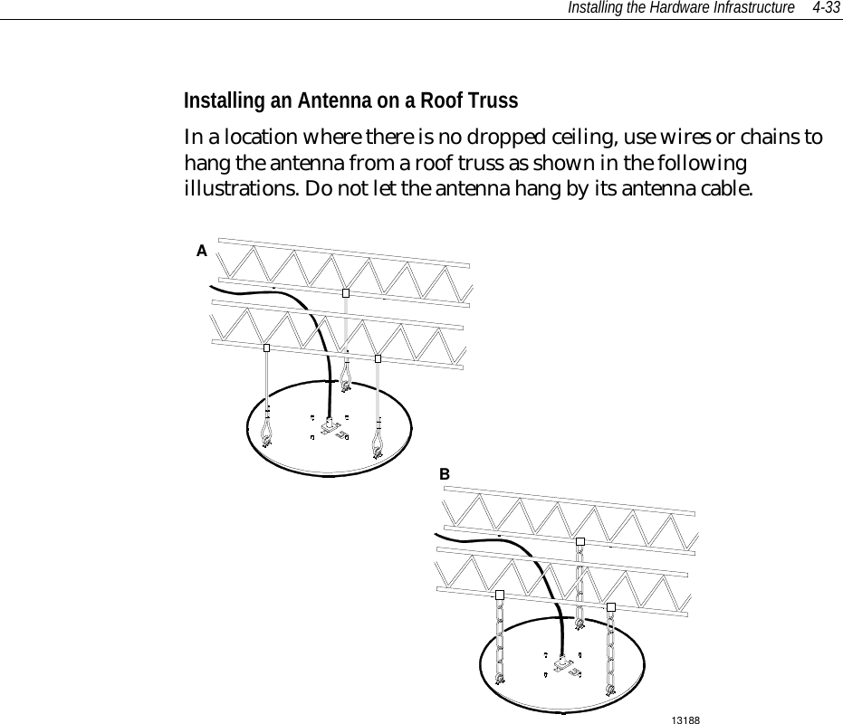
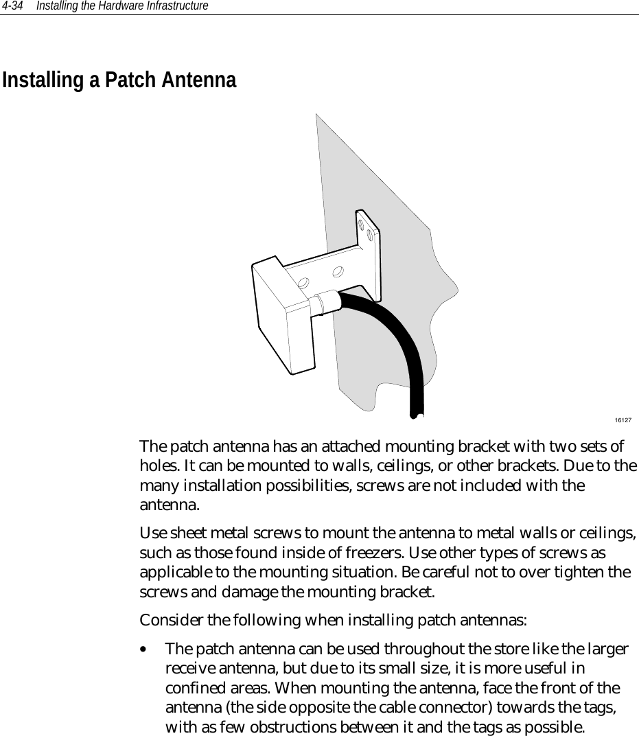
Chapter 4