NCR RSD Atlanta 7710GA2 Electronic Pricing Transmitter User Manual Chapter 12
NCR Corporation, RSD - Atlanta Electronic Pricing Transmitter Chapter 12
Contents
- 1. Users Manual Cover
- 2. Users Manual Front
- 3. Users Manual Glossary
- 4. Users Manual Index
- 5. Users Manual Appendix A
- 6. Users Manual Appendix B
- 7. Users Manual Appedix C
- 8. Users Manual Appedix D
- 9. Chapter 1
- 10. Chapter 2
- 11. Chapter 3
- 12. Chapter 4
- 13. Chapter 5
- 14. Chapter 6
- 15. Chapter 7
- 16. Chapter 8
- 17. Chapter 9
- 18. Chapter 10
- 19. Chapter 11
- 20. Chapter 12
- 21. Chapter 13
Chapter 12

Testing the System
CBS Diagnostics and Troubleshooting
The information in this chapter will assist trained NCR Customer
Service personnel or other trained personnel in analyzing and isolating
problems with the DecisioNet System. The available tools include the
DecisioNet System log, a SmarTalker check called Bedcheck, CBS
diagnostics, and Failure Detection and Analysis (FDA) software.
FDA uses the Base Hardware configuration information to detect and
log hardware failures. FDA is included on the optional EPL System
Information package that must be installed and running to benefit
from its diagnostic and logging capability. For error code descriptions
refer to Chapter 8, “DecisioNet System Messages,” in the NCR
DecisioNet System User’s Guide (B005-0000-1087).
Site-specific documents created during initial installation as specified
in the Certification/Re-Certification Site Survey Procedure (497-0410343)
and provided to the DecisioNet Technical Support Specialist at your
area Managed Service Center includes the following information:
• Installation Site Survey/Checklist
• General site data
• EPL requirements
• Software types and versions
• Price lookup information
• Dial-in support data (passwords, etc.)
Using the dial-in support data, the Managed Service Center can
perform all of the DecisioNet System software testing and
troubleshooting described in this chapter.
12

12-2 Testing the System
Training for the DecisioNet System includes a 7710 Hardware class,
and the DecisioNet Software Support and Programming WBT.
Initiating CBS Diagnostics
The following CBS diagnostics are available:
• Self-Diagnostics (Level 0 tests)
• DIP Switch Diagnostics (Level 1 factory tests)
• EPL Administration Diagnostics (Level 3 tally tests) – requires EPL
Base and Application Runtime software
• Failure Detection and Analysis (Level 2 tests) – requires EPL Base
and Application Runtime and EPL System Information Package
Opening the CBS
The CBS must be opened to access the switches and Light Emitting
Diodes (LEDs) described in the following sections. Refer to the
illustrations in the “Installing Primary and Secondary CBSs” section of
Chapter 4 for instructions on opening the CBS and mounting the CBS.
The safety strap shown around the CBS handle in the CBS Mounting
System illustration must be removed before opening the CBS.
Caution: When opening the CBS with the cables attached, be careful
not to lift the CBS off the mounting bolts or to disconnect any cables.
DIP Switch Settings
When running diagnostic tests, set DSW1 as noted in the following
table.
Test Name DSW1–Switch 4 DSW1–Switch 3
Self-Diagnostics Off Off
DIP Switch Diagnostics Off On
EPL Administration Diagnostics Off Off
Failure Detection and Analysis Off Off
Testing the System 12-3
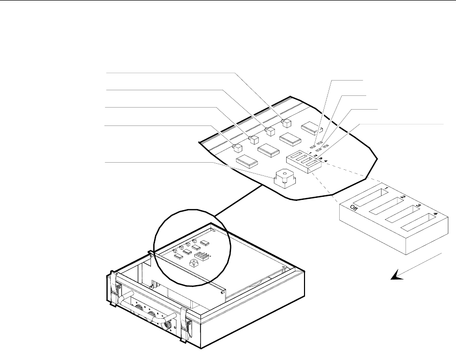
The following illustration shows the rotary switch, DIP switch, and
LED positions.
LED 4
LED 3
LED 2
LED 1
LED 6
LED 7
LED 5
Rotary Switch (DSW2)
Dip Switch (DSW1)
The chassis
handle is in
this direction.
14058
Self-Diagnostics
Self-Diagnostics are ROM-Based (Level 0) diagnostic tests that run
under control of the resident firmware each time the CBS is powered
up with the DSW1 switches set as follows:
• DSW1-Switch 4: Off
• DSW1-Switch 3: Off

12-4 Testing the System
With EPL Software Not Running
With the EPL Software not running, check the basic functionality of the
CBS by turning the power on. Self-Diagnostics performs the following
tests and indicates the test in progress on the LEDs.
Test No.Test Name LED 3LED 4LED 5LED 6LED 7
1 CPU Instruction and Register
Test On Off On On On
2 ROM Test with Sum Check On Off On Off Off
3 RAM Test On Off Off On Off
4 CPU Timer Test On Off On On On
5 CPU ASIC Register Test On Off On On On
6 DSP Test Off On Off Off On
All LEDs are turned off following a successful completion of all the
tests. If an error occurs, the LEDs continue to indicate the test in
progress when the error occurred. Replace the CBS for any condition
other than a successful completion.
With EPL Software Running
With EPL Software running, the LEDs in each CBS should be on or
blinking, as follows, after a successful CBS power up.
LED # - Color Condition/Description
1 - Red On/Power On (This LED is not controlled by the
firmware but is directly connected to the power line.)
2 - Green On/Primary CBS (This LED identifies CBS connected
to the RS-232/RS-422 Converter)
3 - Red Blinking/RS-485 communications active with the EPL
Controller or Primary CBS
4 - Yellow Blinking/RF communications active with SmarTalker
tags
8 - Red Blinking/Master Clock Indicator

Testing the System 12-5
Using the CBS LEDs to Diagnose Problems
The following sections recommend areas to check when the LEDs do
not indicate a successful completion of the Self Diagnostics with EPL
Software running. Refer to the following sections in this guide for
details about system components, cable identification, cable
installation, and cable connector pin out diagrams.
• Chapter 4 – Installing the Hardware Infrastructure
• Appendix B – DecisioNet System Cables
If LED #1 is NOT On
Perform the following steps:
1. Check power supply indicator light to verify that the power supply
is on. If not on, turn on the power switch. Verify that the power
cord is plugged in to a proper power source.
2. Check power supply connections (C048 cable).
3. Check C048 cable connections. Be aware that the C048 cable blocks
DC power.
4. Check cable connections for all extensions.
5. Verify that the RS-495/DC cables (C046 and C048) connector’s pins
match the cable diagrams shown in Appendix B.
If LED #2 is NOT On for the Primary CBS
Perform the following steps:
1. Verify that the RS-422 cable (C051) is properly connected to the RS-
232/RS-422 Converter and make sure the C051 cable is connected
to CBS CON-3.
2. Verify that the RS-485/DC cable (C048) is properly connected to
the power supply and make sure the C048 cable is connected to
CBS CON-1 or CBS CON-2.
3. Verify that the RS-232/RS-422 Converter power light is on. If not,
verify that the power block is plugged in to a proper power source.

12-6 Testing the System
4. Verify that the RS-232/RS-422 Converter is connected to the EPL
controller (RS-232 cable).
5. Verify that the Rx/Tx LEDs are blinking on the RS-232/RS-422
Converter.
6. Make sure that the EPL software is running on the EPL controller.
7. If problems persist, call your NCR Representative and review the
original site certification documents for support.
If LED #3, LED #4 or LED #8 is NOT Blinking
Perform the following steps:
1. Make sure the EPL Software is running.
2. Verify the C046 and C049 cable connections between CBSs.
3. Verify that the Rx/Tx LEDs are blinking on the RS-232/RS-422
Converter.
DIP Switch Diagnostics
These Level 1 Diagnostics are typically performed at the factory to
validate CBS functionality. They are shown here for reference purposes
only. DIP switch diagnostics tests may be run by setting DSW1
switches as follows:
• DSW1-Switch 4: Off
• DSW1-Switch: On
The DIP switch diagnostics tests and their LED indications are as
follows:
Test No. Test Name LED 3 LED 4 LED 5 LED 6 LED 7
1 ROM Test with CRC On Off On Off Off
2 RS-485 Loop Test Off Off Off On On
3 Master Clock Test Off Off On Off On

Testing the System 12-7
All LEDs are turned off following a successful completion of all the
tests. If an error occurs, the LEDs continue to indicate the test in
progress when the error occurred. Replace the CBS for any condition
other than a successful completion.
EPL Administration Diagnostics
The EPL Administration Diagnostics are used to analyze system
performance and to view the CBS tally for function being tested. The
CBS resets all tallies each time the CBS powers up. Tallies are Level 3
diagnostics information.
Note: The installer and/or customer may not need some of this
information, but NCR may request it if contacted for remote support.
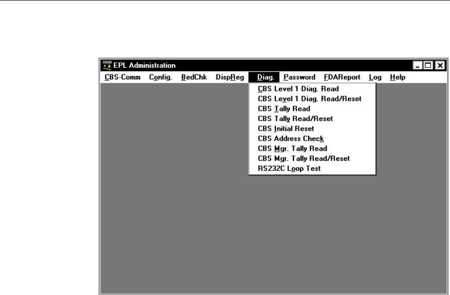
When Diagnostics is selected from the EPL Administration screen, the
following functions are available:
• CBS Level 1 Diagnostics - Read
• CBS Level 1 Diagnostics - Read/Reset
• CBS Tally - Read
• CBS Tally - Read/Reset
• CBS Initial Reset
• CBS Address Check
• CBS Manager Tally - Read
• CBS Manager Tally - Read/Reset
• RS-232 Loop Test
12-8 Testing the System
The following menu is displayed when Diagnostics is selected from
EPL Administration.
Note: After a function is specified in the diagnostics menu, any
specific CBS can be targeted for testing.
Testing the System 12-9
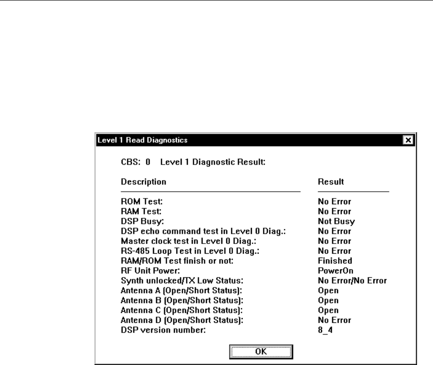
CBS Level 1 Diagnostics - Read or CBS Level 1 Diagnostics -
Read/Reset
This function reads the results of the Level 1 Diagnostics. (CBS Level 1
Diagnostics - Read/Resets reads the results and also resets the tallies.)
The following is an example CBS Level 1 Diagnostics - Read selection
screen.
Note: Synth unlocked/TX Low Status: means Synthesizer Unlock/
Transmit Power Level.
For Antennas A – D, the status indications are:
Open: Receive antenna is not connected
No Error: No error state (receive antenna is connected)
Short: Error state (receive antenna is connected)

12-10 Testing the System
These are the tallies shown in the Level 1 Read Diagnostics screen.
ROM Test: Indicates if the CBS’s ROM is working properly.
RAM Test: Indicates if the CBS’s Ram is working properly.
DSP Busy: Indicates if a CBS’s Digital Signal Processor (DSP) firmware
queries are full.
DSP echo command test in Level 0 Diag.: Indicates if a CBS’s DSP
firmware is working properly.
Master clock test in Level 0 Diag.: Indicates if the Master CBS’s clock
is working properly.
RS-485 Loop Test in Level 0 Diag.: Indicates if a CBS’s RS-485 Port is
working properly. (This is used at the factory only.)
RAM/ROM Test finish or not: Indicates if the RAM/ROM tests have
completed.
RF Unit Power: Indicates if the transmitter is on or off.
Synth unlocked/TX Low Status: Indicates if the two parts of the RF
board are operational. Both need to be working for the RF to be on.
Antenna A (Open/Short Status): Indicates if Antenna A is connected
to the CBS and is working properly.
Antenna B (Open/Short Status): Indicates if Antenna B is connected to
the CBS and is working properly.
Antenna C (Open/Short Status): Indicates if Antenna C is connected
to the CBS and is working properly.
Antenna D (Open/Short Status): Indicates if Antenna D is connected
to the CBS and is working properly.
DSP version number: This is the version number of the CBS’s ROM.
Testing the System 12-11
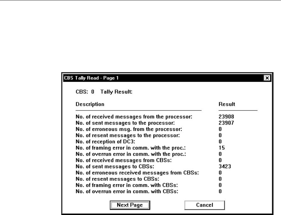
CBS Tally - Read or CBS Tally - Read/Reset
This function retrieves the CBS tallies from each CBS. (CBS Tally -
Read/Reset retrieves the tallies and also resets the tallies.)
The following shows an example CBS Tally - Read selection screen.
These are the tallies shown in the CBS Tally Read screen.
No. of received messages from the processor: This is the number of
messages the Master CBS received from the ISP.
No. of send messages to the processor: This is the number of messages
the Master CBS has sent to the ISP.
No. of erroneous msg. from the processor: This is the number of
messages received from the ISP that have errors.
No. of resent messages to the processor: This is the number of
messages the Master CBS had to resend to the ISP.
No. of reception of DC3: This is the number of DC3 messages the CBS
received telling it to be idle.

12-12 Testing the System
No. of framing error in comm. with the proc.: This is the number of
framing errors that have occurred in messages sent to the CBS from the
ISP.
No. of overrun error in comm. with the proc.: This is the number of
times the CBS could not process a message from the ISP because of
messages being sent too quickly to the CBS from the ISP.
No. of received messages from CBSs: This is the number of messages
a CBS has received from other CBSs.
No. of sent messages to CBSs: This is the number of messages a CBS
has sent to other CBSs.
No. of erroneous received messages from CBSs: This is the number of
messages a CBS has received with errors from other CBSs.
No. of resent messages to CBSs: This is the number of messages a CBS
has resent to other CBSs because there was an error with the original
message sent to the other CBS.
No. of framing error in comm. with CBSs: This is the number of
messages received with framing errors from other CBSs.
No. of overrun error in comm. with CBSs: This is the number of times
the CBS could not process a message from another CBS because
messages were being sent to quickly from the other CBS.
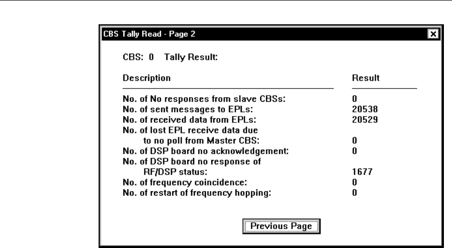
Testing the System 12-13
No. of No responses from slave CBSs: This is the number of times a
CBS sent a message to a satellite CBS and did not get a response.
No. of sent messages to EPLs: This is the number of messages a CBS
sent to a SmarTalker.
No. of received data from EPLs: This is the number of times a CBS
received data from a SmarTalker.
No. of lost EPL rcv. data due to no poll from Master CBS: This is the
number of times EPL data was lost because the Master CBS did not
send a poll for the data.
No. of DSP board no acknowledgment: This is the number of times
the DSP firmware in the CBS did not return an acknowledgment of a
message.
No. of DSP board no response of RF/DSP status: This is the number
of times the DSP firmware in the CBS did not return an RF/DSP status
when requested.
No. of frequency coincidence: This is the number of times the Master
CBS received a message back from multiple satellite CBSs using the
same frequency for the same EPL request.

12-14 Testing the System
No. of restart of frequency hopping: This is the number of times the
Master CBS restarted frequency hopping.
Using CBS Tally Read Information to Diagnose Problems
If No. of erroneous msg. from the processor: exceeds 1 percent of the
total messages, there is a serious problem with the DecisioNet System.
Check the following:
• The EPL controller is functioning properly.
• The RS-232 and RS-422 cables are properly connected.
• There is not a faulty component on the primary CBS.
If No. of erroneous received messages from CBSs: exceeds 1 percent
of the total messages, there is a CBS problem. Check the following:
• The cables between CBSs are not too long. Refer to the section on
“Cables Required for Installation” in Chapter 4, “Installing the
Hardware Infrastructure,” for more information.
• There is not a faulty component on the primary CBS.
If No. of frequency coincidence: is greater than 100, the limit of 20
CBSs installed in the site may have been exceeded or the basesw.cfg
frequency range parameter may be too limited.
CBS Initial Reset
This command resets the CBS to its initial power on state. All CBS
Tallies are set to zero. CBS Manager tallies are not reset.
CBS Address Check
This command is for checking CBS addresses. It causes each CBS to
indicate its address on LEDs 3 and 4 when DSW1 Switch 4 is set to
“On” and DSW1 Switch 3 is set to “Off” as described in the table at the
beginning of this chapter. LED 3 blinks once to indicate the start of the
address, then LED 4 blinks the same number of times as the number of
the address, then LED 3 blinks a final time to indicate the end of the
address.
Testing the System 12-15
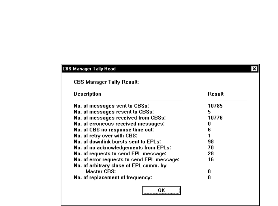
CBS Manager Tally - Read or CBS Manager Tally - Read/Reset
This function retrieves the CBS manager tallies from the primary CBS.
(The CBS Manager Tally - Read/Reset also resets the tallies.)
The following shows a CBS Manager Tally - Read selection screen.
These are the tallies shown in the CBS Manager Tally screen.
No. of messages sent to CBSs: This is the number of messages the CBS
Manager sent to the CBSs since the last time tallies were reset.
No. of messages resent to CBSs: This is the number of messages the
CBS Manager had to resend to the CBSs due to a failure while sending
a request since the last time tallies were reset.
No. of messages received from CBSs: This is the number of messages
the CBS Manager received back from the CBSs.
No. of erroneous received messages: This is the number of messages
the CBS Manager has received with errors from the CBSs.
No. of CBS no response time out: This is the number of times the CBS
timed out waiting for a response from a CBS or a SmarTalker.

12-16 Testing the System
No. of retry over with CBS: This is the number of times the CBS
Manager reached the retry limit in trying to communicate with a CBS.
No. of downlink bursts sent to EPLs: This is the number of downlink
bursts sent to SmarTalkers.
No. of no acknowledgments from EPLs: This is the number of time
the CBS Manager did not get an acknowledgment from a message sent
to a SmarTalker.
No. of requests to send EPL message: This is the number of requests
from the DecisioNet Applications to send a message to a SmarTalker.
No. of error requests to send EPL message: This is the number of
times the CBS Manager received a request to send a message to a
SmarTalker.
No. of arbitrary close of EPL comm. by Master CBS: This is the
number off times the Master CBS was powered-off, then -on, plus the
number of times it was reset with the Initial Reset command.
No. of replacement of frequency: This is the number of times the CBS
Manager had to change or replace a frequency in the frequency-
hopping screen.
RS-232 Loop Test
The RS-232 port on the controller may be tested using this function. A
turnaround plug must be installed before initiating this test.
Diagnostic Logs
Access the following logs from the EPL Administration or EPL
Maintenance application Log menu:
• EPL System Error Log
• EPL Data Send Log
• EPL Audit Log
Testing the System 12-17
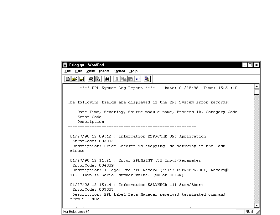
EPL System Error Log
The following shows an example EPL System Error Log report. The
EPL System Error Log contains a record of all errors logged by the EPL
base software and applications.
Information in the System Error Log includes:
Date and Time the error occurred
Severity Code: Information, Warning, Error
Source module name of the application that logged the error
Process ID number for the application that logged the error
Category Code for the application that logged the error
Error Code that identifies the error
Description of the error
For more information on interpreting errors, refer to Chapter 8 in the
NCR DecisioNet System User’s Guide (B005-0000-1087).
12-18 Testing the System
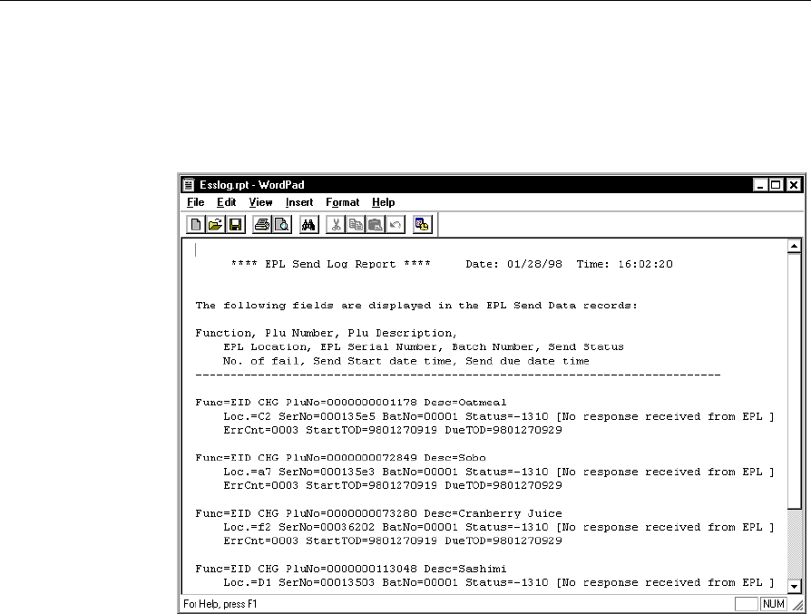
EPL Data Send Log
The following is an example of the EPL Data Send Log. A Data Send
log record is recorded when an EPL update is scheduled.
Information in the EPL Data Send Log includes:
Function: The function that started this operation
PLU Number: The item number
PLU Description: A description of the item
Location: The SmarTalker location
Serial Number: The SmarTalker serial number
Batch Number: The EPL Maintenance Batch Number

Testing the System 12-19
Send Status:
An EPL’s status is indicated by a number and brief message
0: Successful
1: Waiting
2: Communicating
Any Negative Number: Resend the data using the instructions in the
section “Resending the EPL Data” in Chapter 9. Refer to Chapter 8,
“DecisioNet System Messages,” in the NCR DecisioNet System User’s
Guide (B005-0000-1087), for message descriptions.
No. of Fail: The number of communication errors
StartTOD: Date and time when communication starts
(9708302102 = YYMMDD and 24-hour time)
DueTOD: Date and time when communication is due to be completed
(9708302112 = YYMMDD and 24-hour time)

12-20 Testing the System
EPL Audit Log
The following is an example of the EPL Audit Log, which shows
information relating to the updating of the EPL Table.
Information in the EPL Audit Log includes:
• Date and Time EPL Table entry occurred
• The type of Maintenance Function performed
• SmarTalker Serial Number
• Price Lookup (PLU) Number
• Shelf or Store Location (optional)
• PLU Description
• Maintenance information including Batch Number and Record
Number within the Batch

Testing the System 12-21
Using Failure and Detection Analysis Software
Failure Detection and Analysis (FDA) software can be used as a
background service to report on the condition of DecisioNet System
hardware. FDA is one of the applications on the optional EPL System
Information Package.
Power supply, CBS, and antenna failures are reported to the EPL
System Error Log. Errors related to SmarTalker tags are logged in the
Bedcheck log and a corresponding entry in the EPL System Error Log
indicates the number of tags affected.
In a Windows NT system, FDA also logs error conditions to the
Windows NT Event Log. These entries include Probable Cause and
Recommended Action information.
The following types of errors are logged by FDA:
Error Description
CBS communication closed CBS not communicating with
SmarTalkers
Master CBS link down ISP cannot communicate with
Master CBS
RS-485 cable failure FDA software identifies faulty cable
Power supply failure FDA software identifies faulty
power supply
CBS not connected CBS cannot be detected
Too many CBSs connected RS-485 link cannot handle traffic
CBS diagnostic errors have
occurred FDA software identifies faulty CBS
Unconfigured CBS detected CBS not configured
CBS connected, but not
communicating CBS Manager is not using CBS
CBS not receiving master RS-485 cable problem

12-22 Testing the System
Error Description
clock signal
Unconfigured CBS detected
and communicating CBS not configured
CBS RF power is off CBS RF board is not working
properly
Receive antenna not working
properly Receive antenna needs to be
replaced
Unconfigured receive
antenna is functioning Receive antenna not configured
Ambient noise exceeds
threshold CBSs cannot communicate with
SmarTalkers properly
Signal level threshold is too
high CBSs cannot communicate with
SmarTalkers properly
SmarTalkers not responding Quantity specified
SmarTalkers have battery
low condition Quantity specified
SmarTalkers have hardware
error condition Quantity specified
FDA also records the CBS tally information in the tally files and
forwards tallies to Store Minder. See the “EPL Administration
Diagnostics” section in this chapter for information about accessing
tally information.

Testing the System 12-23
Running FDA from a System Prompt
When started with other EPL Applications, FDA runs continuously
and logs errors as they occur. Use the following procedures to run
FDA in single-pass mode. The results of the report are sent to the
console and placed in the EPL System Error Log. Use the -f command
line option to save the report to a file for viewing and printing.
1. At a DOS or UNIX prompt, enter esfda to start FDA in single-pass
mode.
2. Review the information output to the console screen, the EPL
System Error Log and Windows NT Event Log (if testing on
Windows NT system).
The syntax and options for esfda are as follows:
esfda [-r][-x][-y][-f<filename>]
-r Report on software and hardware components
-x Report only on the hardware components
-y Report only on the software components
-f<x> Save report in the file specified by <x>. If a path is not
specified, the file is placed in the epl/data/status
directory.
Example:
• Run a hardware and software test and place the report in a file
named fdatest.
esfda -rf fdatest
The following is our report created for the example above.

12-24 Testing the System
---------------------------------------------------------------
(04/16/99)15:39 System Status Report NCR
Corp
---------------------------------------------------------------
Component : EPL
Status : Ok
Component : CBS Link
Status : Ok
Component : Failure Detection and Analysis
Status : Ok
Component : CBS 0
Status : NOT OK
Meaning : Unconfigured receive antenna A for CBS 0
Probable Cause : An unconfigured functional receive antenna
was found.
Recommended Action : The specified receive antenna is
improperly configured.
Component : CBS 0
Status : NOT OK
Meaning : Receive antenna B failure for CBS 0
Probable Cause :
Recommended Action : The specified receive antenna is
improperly connected or faulty.
Component : Bedcheck
Status : Ok
Component : EPL Bridge
Status : Ok
Component : CBS Manager
Status : Ok
Component : External Data Interface
Status : Ok
Component : Label Data Manager
Status : Ok

Testing the System 12-25
Component : Logger
Status : Ok
Component : PLU Reader
Status : Ok
Component : Price Checker
Status : Ok
Component : Price Verifier
Status : Ok
Component : Promotional Message Verifier
Status : Ok
Component : Data Scheduler
Status : Ok
Component : Sales Price Verifier
Status : Ok
Component : Table Manager
Status : Ok
---------------------------------------------------------------
12-26 Testing the System
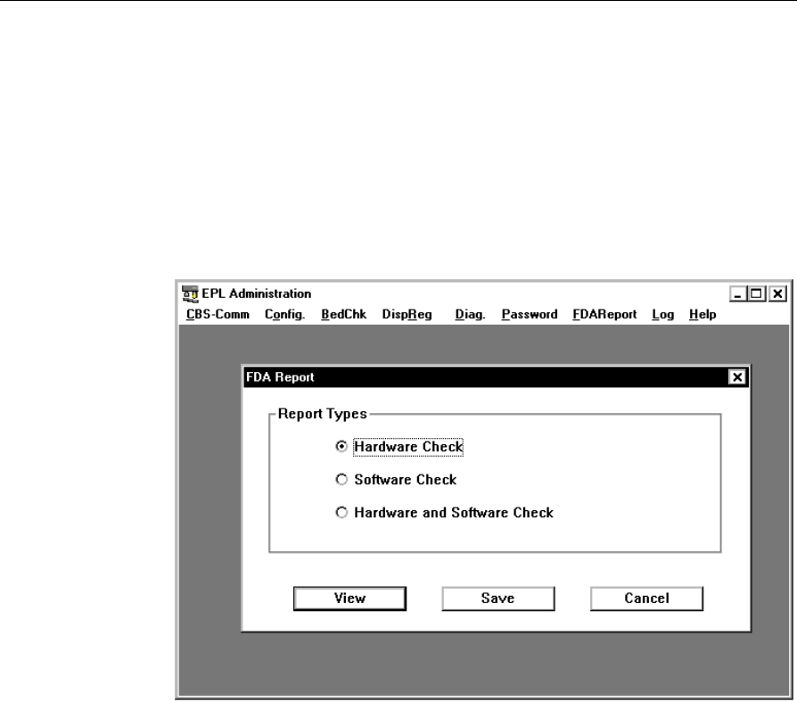
Running FDA from EPL Administration
A single–pass Failure Detection and Analysis (FDA) report on the
condition of DecisioNet System hardware and software can be created
by selecting FDA Report from the EPL Administration screen.
The following menu is displayed when FDA Report is selected from
EPL Administration.
After selecting the Report Type, select View or Save. If View is
selected, the report is created and displayed. If Save is selected, you are
prompted to enter a path and file name. After entering a path and file
name, select Save to create the report and save it in the specified
location.
Refer to the FDA error and description table in the previous section
“Using Failure and Detection Analysis Software” for an explanation of
any errors.

Testing the System 12-27
Bedcheck
Bedcheck verifies if SmarTalkers are working properly. Access the
Bedcheck functions on the EPL Administration application BedChk
menu.
When this function starts, it continues execution as a background
process until completion or until execution is aborted. The bedcheck
errors are stored in the bedcheck log file for later analysis by the user.
The DecisioNet software provides the following functions to control
the bedcheck process.
Function Name Function
Start Bedcheck This function is used to start the bedcheck
process to a specified SmarTalker.
Stop Bedcheck This function is used to terminate bedcheck
execution.
Query Status This function is used to get bedcheck status
when running. The DecisioNet software
returns the number of passed or failed
SmarTalkers that have been processed already.
Read Bedcheck
Log This function is used to read one record
sequentially from the bedcheck log file.
Purge Bedcheck
Log This function is used to delete the log records
that have been read by the "Read Bedcheck
Log" function.
For more information on the Bedcheck function, refer to the NCR
DecisioNet System User’s Guide (B005-0000-1087).

12-28 Testing the System
Analyzing SmarTalker Problems
The following table shows some of the errors that may occur with
SmarTalkers and the possible remedies. These types of errors are
logged in the EPL System Error Log if the Failure Detection and
Analysis software is installed in your system.
Error Causes Possible Remedies
No Response
A black dot (●)
displays on the LCD
Out of sync. Remove the obstacle between the
CBS and the SmarTalker. Contact
your NCR representative and
review the original site
certification documents to see
what change may have caused the
problem. Reference the
Certification/Re-certification Site
Survey Procedure (497-0410343) for
details on the site certification
process.
EPL No Response Hardware trouble
including battery loss Replace with new SmarTalker.
Refer to Chapter 10 or 11.
EPL No Response No existence in the store. Perform a Replace EPL function as
described in the “Replace EPL”
section of the EPL Maintenance
chapter in the NCR DecisioNet
System User’s Guide
(B005-0000-1087).
EPL Battery Low
The low battery
symbol ( ) displays.
EPL Battery Low Replace with new SmarTalker.
Refer to Chapter 10 or 11.

Testing the System 12-29
FDA uses the Base Hardware configuration information to detect and
log hardware failures. FDA is included on the optional EPL System
Information package that must be installed and running to benefit
from its diagnostic and logging capability. For error code descriptions
refer to Chapter 8, “DecisioNet System Messages,” in the NCR
DecisioNet System User’s Guide (B005-0000-1087).
Site-specific information created during the initial installation as
specified in the Certification/Re-Certification Site Survey Procedure
(497-0410343) and provided to the DecisioNet Technical Support
Specialist at your area Managed Service Center includes the following
information:
• Installation Site Survey/Checklist
• General site data
• EPL requirements
• Software types and versions
• Price lookup information
• Dial-in support data (passwords, etc.)
Using the dial-in support data, the Managed Service Center can
perform all of the DecisioNet System software testing and
troubleshooting described in this chapter.

12-30 Testing the System