NCR RSD Atlanta 7710GA2 Electronic Pricing Transmitter User Manual Chapter 13
NCR Corporation, RSD - Atlanta Electronic Pricing Transmitter Chapter 13
Contents
- 1. Users Manual Cover
- 2. Users Manual Front
- 3. Users Manual Glossary
- 4. Users Manual Index
- 5. Users Manual Appendix A
- 6. Users Manual Appendix B
- 7. Users Manual Appedix C
- 8. Users Manual Appedix D
- 9. Chapter 1
- 10. Chapter 2
- 11. Chapter 3
- 12. Chapter 4
- 13. Chapter 5
- 14. Chapter 6
- 15. Chapter 7
- 16. Chapter 8
- 17. Chapter 9
- 18. Chapter 10
- 19. Chapter 11
- 20. Chapter 12
- 21. Chapter 13
Chapter 13

Maintenance
Replacing DecisioNet Hardware
Except for the SmarTalker II battery replacement described in this
chapter, the DecisioNet System hardware does not require any
preventive maintenance. If there is a problem, trained NCR Customer
Service personnel or other trained personnel can use the information in
Chapter 12, “Testing the System,” to analyze and isolate the problem.
DecisioNet hardware is not field repairable. If it is determined that a
CBS, antenna, power supply, or SmarTalker is defective, use the
procedures described in this chapter to replace the unit with a new
one. If appropriate, contact your NCR representative for information
on where to send the defective unit for repair.
Caution: When replacing a 7710-1000 CBS with a 7710-1002 CBS or
when adding a 7710-1002 CBS to an existing 7710-1000 CBS system, the
power supply servicing the portion of the system where the
7710-1002 CBS will be connected may require a new power supply. If
the existing power supply is a 008-0214527, replace it with a new
497-0410951 (Assembly: 497-0410962) power supply.
13

13-2 Maintenance
Replacing a CBS
Use this procedure to replace a suspected malfunctioning CBS with
another one.
1. Stop CBS communication using Start/Stop CBS Comm in the EPL
Administration window.
2. Power off all the CBSs in the system by powering off the power
supplies.
3. After noting its switch positions, disconnect and remove the
malfunctioning CBS.
4. Set the switches in the new CBS to match the switches in the CBS
you are replacing.
5. Install the new CBS and reconnect the cables where they were
connected before. All connectors are keyed to prevent improper
insertion.
6. Power up all CBSs in the system.
7. Re-start CBS communication using Start/Stop CBS Comm in the
EPL Administration window.
8. Confirm that the green LEDs in the receive antennas are lit. If they
are not lit, then either the CBS is not getting power or the antennas
are not connected to the CBS.
Note: After removing or replacing the CBS or a transmit antenna, it is
recommended that you re-certify RF communications. It is also
recommended that the change in the site configuration be noted for
support purposes. For more information, contact your NCR
representative and reference the following:
• B005-0000-1138: DecisioNet Support Tools Reference Guide (document)
• G370-1182-0000: EPL Implementation Package for Windows 95/NT
(disk media containing the EPL RF Certification Package)
• 497-0410343: Certification/Re-certification Site Survey Procedure
(to document site configuration for support purposes)

Maintenance 13-3
Replacing a Receive Antenna
Use this procedure to replace a suspected malfunctioning antenna.
1. Disconnect and remove the malfunctioning antenna.
2. Install and re-connect the new antenna. The receive and transmit
antenna connectors are different, helping you to determine the
correct connections.
3. Confirm that the green LED in the new receive antenna is lit. If it is
not, then there is a problem between the antenna and the CBS.
4. Confirm that errors related to the replaced antenna are no longer
being logged.
Replacing a Patch Antenna
Use this procedure to replace a suspected malfunctioning antenna.
1. Disconnect and remove the malfunctioning antenna.
2. Install and re-connect the new antenna. The receive and transmit
antenna connectors are different, helping you to determine the
correct connections.
3. Confirm that errors related to the replaced antenna are no longer
being logged.

13-4 Maintenance
Replacing a Transmit Antenna
Use this procedure to replace a suspected malfunctioning transmit
antenna. You MUST remove power from the CBSs during this
procedure. Removing a transmit antenna from a powered CBS can
damage the CBS transmitter circuitry.
1. Stop CBS communication using Start/Stop CBS Comm in the EPL
Administration window.
2. Power off all the CBSs in the system by powering off the power
supplies.
3. Disconnect and remove the malfunctioning transmit antenna.
4. Install the new transmit antenna. The receive and transmit antenna
connectors are keyed differently, helping you to connect the new
antenna correctly.
5. Power up all CBSs in the system.
6. Re-start CBS communication using Start/Stop CBS Comm in the
EPL Administration window.
Note: After removing or replacing the CBS or a transmit antenna, it is
recommended that you re-certify RF communications. It is also
recommended that the change in the site configuration be noted for
support purposes. For more information, contact your NCR
representative and reference the following:
• B005-0000-1138: DecisioNet Support Tools Reference Guide (document)
• G370-1182-0000: EPL Implementation Package for Windows 95/NT
(disk media containing the EPL RF Certification Package)
• 497-0410343: Certification/Re-certification Site Survey Procedure
(to document site configuration for support purposes)

Maintenance 13-5
Replacing a Power Supply
Use this procedure to replace a suspected malfunctioning power
supply.
1. Stop CBS communication using Start/Stop CBS Comm in the EPL
Administration window
2. Power off all the CBSs in the system by powering off the power
supplies.
3. Disconnect and remove the malfunctioning power supply.
4. Install a new power supply.
5. Power up all power supplies in the system.
6. Re-start CBS communication using Start/Stop CBS Comm in the
EPL Administration window.
7. Confirm that the green LEDs in the receive antennas are lit. If they
are not lit, then either the CBS is not getting power or the antennas
are not connected to the CBS.
Replacing a SmarTalker
For SmarTalker installation and removal information, refer to Chapter
10, “SmarTalker and Rail Installation.”
Replacing a SmarTalker II
For SmarTalker II installation and removal information, refer to
Chapter 11, “SmarTalker II and Rail Installation.”
13-6 Maintenance
Battery Replacement
SmarTalker Battery Replacement
When a SmarTalker’s battery becomes weak, the battery symbol in the
display lights and the SmarTalker must be replaced with a new
SmarTalker. The SmarTalker’s case cannot be opened and the battery
inside cannot be replaced.
Because the battery contains lithium, the SmarTalker must be disposed
of in accordance with local environmental laws and ordinances.
SmarTalker II Battery Replacement
When a SmarTalker II’s batteries become weak, the battery symbol in
the display lights indicating that its two lithium batteries must be
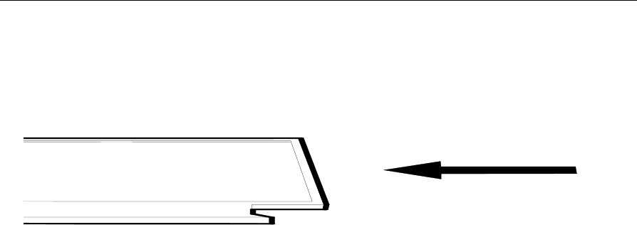
replaced. After removing the SmarTalker II from the shelf, remove the
back cover from the SmarTalker II as shown in the following
illustration.
16919
Opening the SmarTalker II
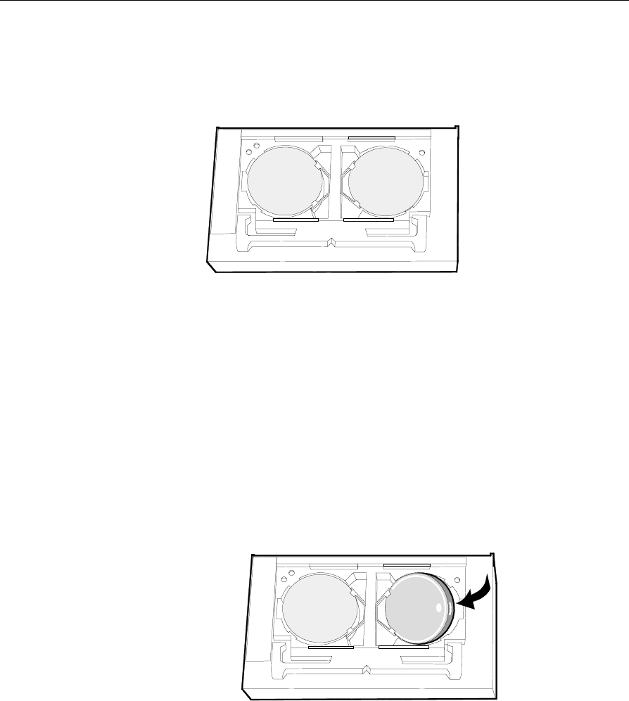
Caution: Do not remove both batteries at the same time. If the both
batteries are removed at the same time, the tag will “forget” its serial
number and display information. To prevent this from happening, the
batteries must be replaced one at a time.
Maintenance 13-7
After removing the back cover, remove one battery the from
SmarTalker II by inserting a very small flat-tip screwdriver into the slot
at the edge of the battery and gently prying the battery out.
16920
Slots for Battery Removal
Caution: Danger of explosion if battery is incorrectly replaced.
Replace only with same or equivalent type as recommended by the
manufacturer. Discard used batteries according to the manufacturer’s
instructions.
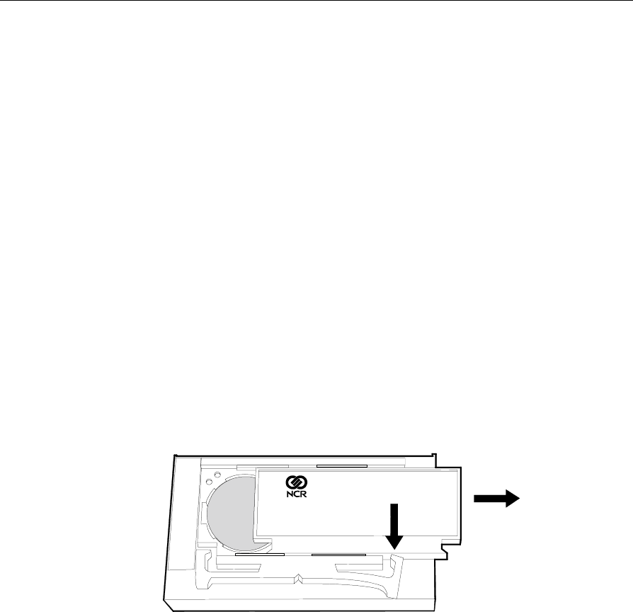
Install a new battery in the SmarTalker II by placing it in the battery
cavity, allowing it to rest under and against the battery clip, and then
gently sliding the battery towards the battery clip and down into the
cavity.
16921
Installing a Battery
13-8 Maintenance
Repeat the process for the second battery. After replacing both
batteries, install the back cover by using the cover to depress the right
pawl, aligning the cover with the top and bottom slides, and then
sliding the cover closed.
16922
Closing the SmarTalker II