NIKON TRIMBLE NT0001 Bluetooth module User Manual Nivo manual 2
NIKON-TRIMBLE CO., LTD. Bluetooth module Nivo manual 2
UserManual.wiki
>
NIKON TRIMBLE
>
NT0001 User Manual
>
Host 2 user manual 2 of 3
Contents
1.
Host 1 user manual 1 of 4
2.
Host 1 user manual 2 of 4
3.
Host 1 user manual 3 of 4
4.
Host 1 user manual 4 of 4
5.
Host 2 user manual 1 of 3
6.
Host 2 user manual 2 of 3
7.
Host 2 user manual 3 of 3
8.
Host 3 user manual 1 of 2
9.
Host 3 user manual 2 of 2
Host 2 user manual 2 of 3
Navigation menu
Upload a User Manual
Namespaces
Wiki Guide
HTML
PDF
Info
Views
User Manual
Discussion / Help
Navigation
![2 Preparation12 Total Station Nivo Series Instruction ManualDetaching and Re-Attaching the Battery PackDetaching the battery packCCAUTION – Avoid touching the contacts on the battery pack.1. If the instrument is turned on, press [PWR] to turn it off.2. Turn the battery box release knob counterclockwise, open the battery box cover and remove the battery pack from the battery box.Inserting the battery packBefore inserting the battery pack, clear any dust or other foreign particles from the battery contacts.1. Turn the battery box release knob counterclockwise and open the battery box cover.2. Put the battery pack into the battery box. Insert the battery pack with the connectors bottom first, facing inside.3. Close the battery box cover and turn the knob clockwise until the secure click sound is heard.CCAUTION – If the battery box cover is not closed, this could adversely affect the watertightness of the instrument.123](https://usermanual.wiki/NIKON-TRIMBLE/NT0001.Host-2-user-manual-2-of-3/User-Guide-1089794-Page-6.png)
![Total Station Nivo Series Instruction Manual 17Preparation 2Setting the Measurement Mode and Preparing the TargetThe Nivo series has two measurement modes: Prism mode (Prism) and Reflectorless mode (N-Prism). These modes can be changed at any time by holding down the [MSR1] or [MSR2] key for one second. For more information, see Measurement settings, page 48.To set the measurement mode depending on the target you want to measure, see the following table. In some cases, you can measure another target that is not appropriate to the set measurement mode.Note – The Nivo series is Laser Class 1 in the measurement function, and Laser Class 2 in the Laser pointer function.Don’t sight the Prism when the Laser Pointer is on.Measurement with a prismDo not use a prism with scratches, a dirty surface, or a chipped center. Prisms with thin edges are recommended.As the Nivo series is extremely sensitive, multiple reflections on the prism surface can sometimes cause a significant loss in accuracy.To maintain the accuracy of your measurements:Target Target settingPrism, reflector sheet Prism (Prism mode)Other (reflective materials) N-Prism (Reflectorless mode)thin edges chipped center thick edges✓✕✕](https://usermanual.wiki/NIKON-TRIMBLE/NT0001.Host-2-user-manual-2-of-3/User-Guide-1089794-Page-11.png)
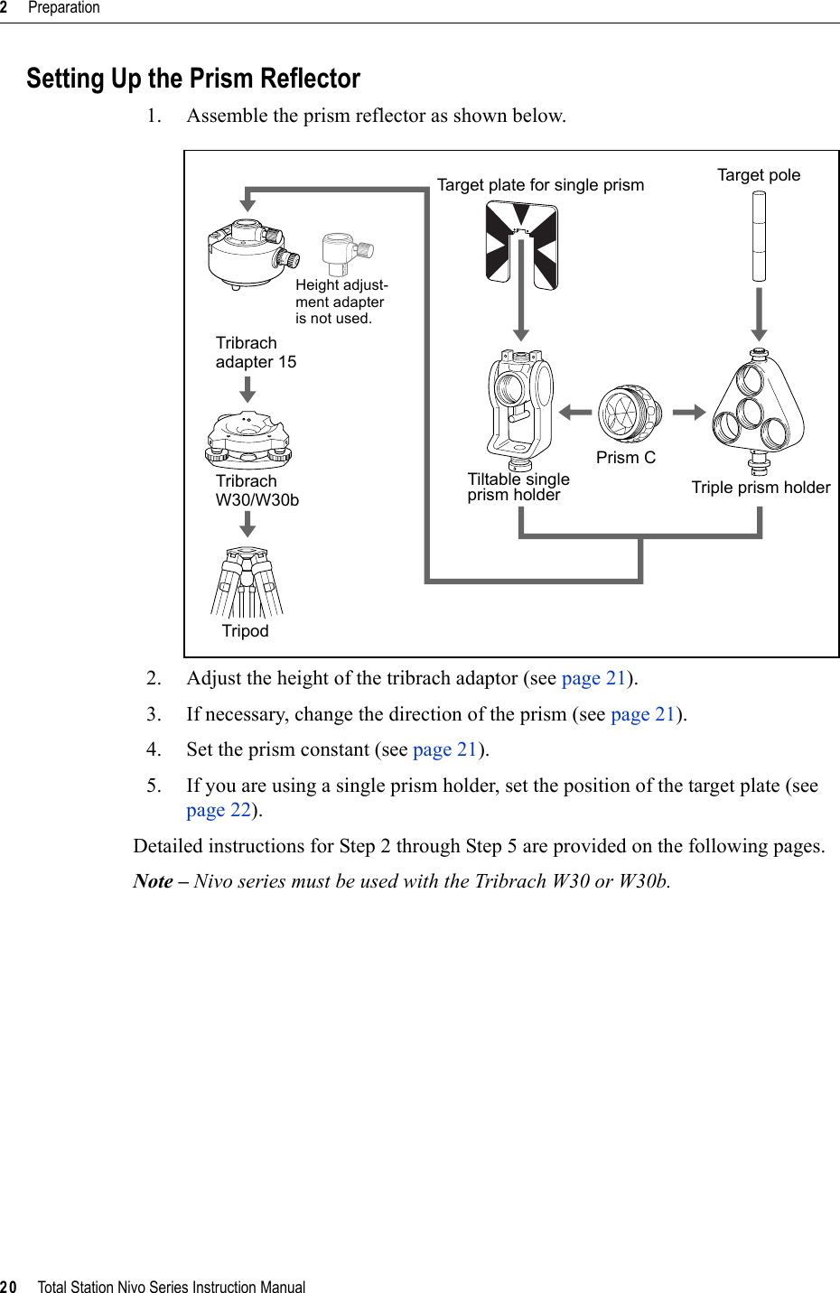
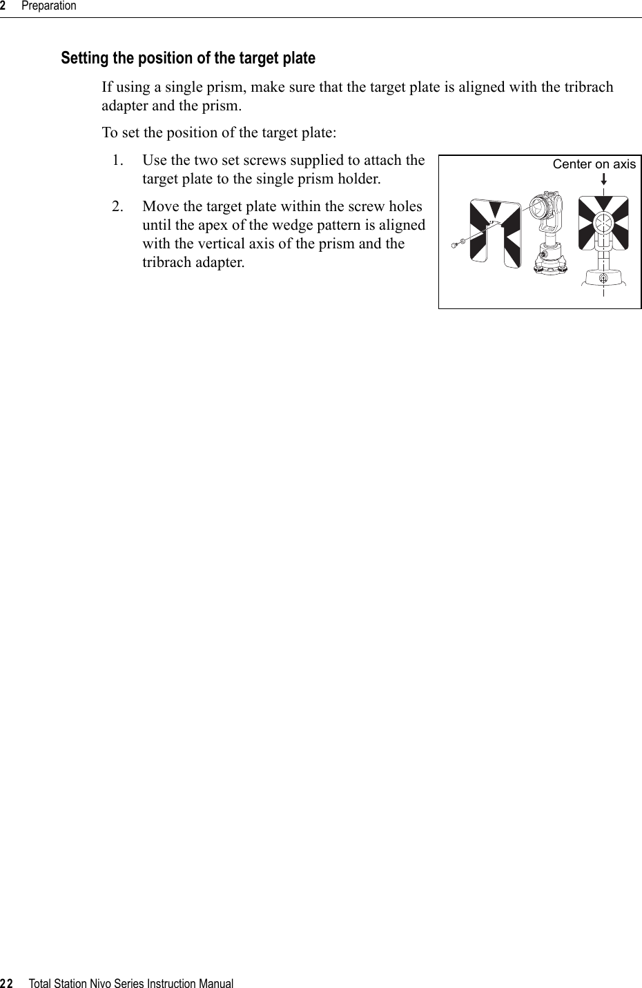
![Total Station Nivo Series Instruction Manual 21Preparation 2Adjusting the height of the tribrach adapterThe tribrach adapter has a height adjustment adapter. To use the prism reflector with a Nivo series instrument, remove the height adjustment adapter as shown in the Figure below.The height adjustment adapter will be used with other Nikon Total Stations.Changing the direction of the prismThe prism mounted on the tribrach adapter can be rotated to face in any direction.To change the direction of the prism:1. Release the rotation clamp. To do this, turn the clamp lever counterclockwise.2. Turn the upper plate of the tribrach adapter until the prism is facing in the required direction.3. Fasten the rotation clamp. To do this, turn the clamp lever clockwise.Setting the prism constant1. Attach the prism to the single prism holder or triple prism holder. BTip – To use a triple prism holder as a single prism holder, attach the prism to the center thread of the prism holder.2. Set the prism constant. To do this, hold down [MSR1] or [MSR2] for one second. For more information, see Measurement settings, page 48.Note – The prism constant of a Nikon prism is always 0, whether it is attached to a single prism holder or a triple prism holder.BTip – When you use the prism at a short distance, set the prism at a slight angle to the sighting axis, rather than completely square.If your prism constant is not 0 mm, then directly enter the prism constant value in the Const field. For example, if your prism constant is 30 mm, enter 30mm in the Const field on the instrument.Height adjustment adapterHeight adjustment adapter clamp screwClampClamp leverUnclamp](https://usermanual.wiki/NIKON-TRIMBLE/NT0001.Host-2-user-manual-2-of-3/User-Guide-1089794-Page-15.png)
![3 Getting Started24 Total Station Nivo Series Instruction ManualTurning the Instrument On and OffTurning on the instrument1. To turn on the instrument, press [PWR]. The start-up screen appears. It shows the model name, current temperature, pressure, date, and time.The display automatically changes to the electronic level after 2 seconds.Turning off the instrumentTo enter the power-off process, press [PWR] and [ENT].Then do one of the following:Sleep modeIf you press the Sleep softkey in the Press [ENT] →OFF screen, or enable the Power Save setting (see Power saving, page 110), the instrument goes into sleep mode. When the instrument is in sleep mode, it wakes up if any of the following occurs:•You press a key•The instrument receives a remote control commandIf you have entered your name or your company’s name in the Owner’s detail field, the text from this field appears on the start-up screen. To set the Owner’s detail field, go to MENU > Settings > Others. For more information, see page 113.Press ... To ...[ENT] again turn off the instrumentthe Reset softkey reboot the program and re-start the instrument the Sleep softkey put the instrument into power-saving mode[ESC] cancel the power-off process and return to the previous screenIf you press the Reset softkey, the software is rebooted and the Basic Measurement Screen (BMS) appears without an open job.](https://usermanual.wiki/NIKON-TRIMBLE/NT0001.Host-2-user-manual-2-of-3/User-Guide-1089794-Page-18.png)
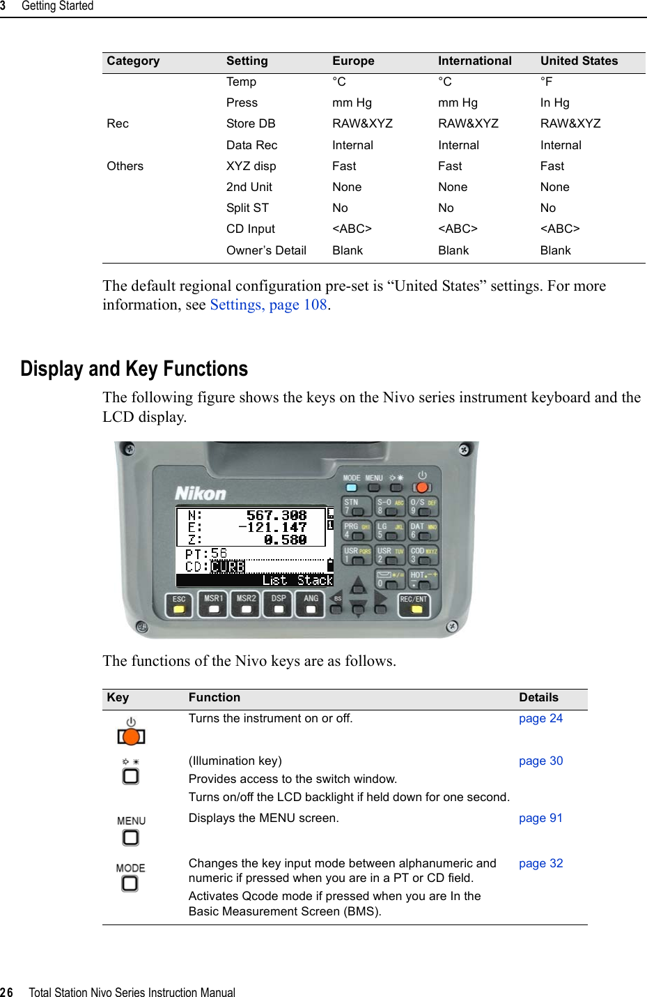
![Total Station Nivo Series Instruction Manual 25Getting Started 3•You rotate the alidade•You tilt the telescopeChanging Regional Configuration Pre-setsTo provide easier configuration for common regional settings, you can quickly configure the Nikon total station to a pre-set combination of default regional settings. The Regional Configuration screen appears only after the language configuration is complete, the instrument has rebooted.1. Follow the steps in Language, page 113.Once the instrument rebooted, the Regional Configuration screen appears.2. Press [^] or [v] to highlight the required regional settings and then press [ENT].3. If you do not want to change the current settings, press [ESC] and quit. The instrument will continue to use the last configured settings that were configured.The settings affected by the Regional Configuration screen are:Category Setting Europe International United StatesAngle VA zero Zenith Zenith ZenithResolution 1"(See note) 1"(See note) 1"(See note)HA Azimuth Azimuth AzimuthDistance Scale 1.000000 1.000000 1.000000T-P corr. On On OnSea Level Off Off OffC&R corr. 0.132 0.132 0.132Coordinates Order ENZ ENZ NEZLabel ENZ ENZ NEZAZ zero North North NorthPower Save Main Unit Off Off OffEDM Unit Off Off OffSleep 5 minutes 5 minutes 5 minutesCommunication Ext. Comm Nikon Nikon NikonBaud 4800 4800 4800Length 8 8 8Parity None None NoneStop bit 1 1 1Stakeout Add PT 1000 1000 1000Units Angle GON DEG DEGDistance meters meters US-ft](https://usermanual.wiki/NIKON-TRIMBLE/NT0001.Host-2-user-manual-2-of-3/User-Guide-1089794-Page-19.png)
![Total Station Nivo Series Instruction Manual 27Getting Started 3Records measured data, moves on to the next screen, or confirms and accepts the entered data in input mode.You have the option to record the measurement as a CP record instead of an SS record, if you hold this key down for one second in the Basic Measurement Screen (BMS).The instrument outputs the current measurement data (PT, HA, VA, and SD) on the COM port if you press this key in the BMS or in a Stakeout observation screen. (The Data Rec settings must be set to COM.) page 81Returns to the previous screen.In numeric or alphanumeric mode, deletes input.Starts distance measurement, using the measure mode settings for the [MSR1] key. Displays measurement mode settings, if held down for one second.page 47Starts distance measurement, using the measure mode settings for the [MSR2] key. Displays measurement mode settings, if held down for one second.page 47Moves to the next available display screen.Changes the fields that appear on the DSP1, DSP2, and DSP3 screens, if held down for one second.page 49Displays the Angle menu. page 52Displays the Station Setup menu.In numeric mode, enters 7. In alphanumeric mode, enters 7.page 53Displays the Stakeout menu.Shows stakeout settings, if held down for one second.In numeric mode, enters 8. In alphanumeric mode, enters A, B, C, or 8.page 64Displays the Offset Point Measurement menu. In numeric mode, enters 9. In alphanumeric mode, enters D, E, F, or 9.page 83Displays the Programs menu, which contains additional measuring programs.In numeric mode, enters 4. In alphanumeric mode, enters G, H, I, or 4.page 71In numeric mode, enters 5. In alphanumeric mode, enters J, K, L, or 5.Displays RAW, XYZ, or STN data, depending on your setting.In numeric mode, enters 6. In alphanumeric mode, enters M, N, O, or 6.page 38Key Function Details](https://usermanual.wiki/NIKON-TRIMBLE/NT0001.Host-2-user-manual-2-of-3/User-Guide-1089794-Page-21.png)
![3 Getting Started28 Total Station Nivo Series Instruction ManualStatus barThe status bar appears on the right side of every screen. It contains icons that indicate the status of various system functions. Input mode indicatorThe Input mode indicator only appears when you are entering points or coordinates. It shows the data input mode:Laser pointer indicatorThe icon appears while turning on the laser pointer. When the icon is displayed on the screen, the emitting power is laser class 2.Executes the function that is assigned to the [USR1] key.In numeric mode, enters 1. In alphanumeric mode, enters P, Q, R, S, or 1.Executes the function that is assigned to the [USR2] key.In numeric mode, enters 2. In alphanumeric mode, enters T, U , V, or 2.page 37Opens a window where you can enter a code. The default code value is the last code entered.In numeric mode, enters 3. In alphanumeric mode, enters W, X, Y, Z, or 3.page 33Displays the (HOT) menu, which includes Height of Target, Temp-Press, Target, Note recording, and Default PT settings.In numeric mode, enters – (minus). In alphanumeric mode, enters . (period), – (minus), or + (plus).page 34Displays the Bubble indicator.In numeric mode, enters 0. In alphanumeric mode, enters *, /, =, (a space), or 0.page 36Input mode is numeric. Press a key on the number pad to enter the number printed on the key.Input mode is alphabetic. Press a key on the number pad to enter the first letter printed beside the key. Press the key repeatedly to cycle through all the letters assigned to that key. For example, to enter the letter O in alphabetic mode, press [5] three times.Laser pointer ON.(None) Laser pointer OFF.Key Function Details Status bar](https://usermanual.wiki/NIKON-TRIMBLE/NT0001.Host-2-user-manual-2-of-3/User-Guide-1089794-Page-22.png)
![3 Getting Started30 Total Station Nivo Series Instruction ManualLCD backlight, Laser pointer, Beep sound and Contrast adjustmentTo turn on/off the 1. LCD backlight, 2. laser pointer or 3. beep sound, and to do the 4. contrast adjustment, press the illumination key and open the switch set up window shown above.Holding down the illumination key for one second also turns on/off the LCD backlight.•To turn on/off each function, press [ENT] when the option 1, 2, 3 or 4 is selected or directly press [1],[2],[3] or [4] numeric key.•Press [^] or [v] to move the cursor up and down.•In the contrast adjustment window, use [^] or [v] to adjust the contrast.To close the window, press [ESC].1. LCD backlight2. Laser pointer3. Sound[ENT] /[4][ESC]<Switch set up window > <Contrast adjustment window>LCD backlight is OFFLCD backlight is ONLaser pointer is OFFLaser pointer is ONSound is OFFSound is ON](https://usermanual.wiki/NIKON-TRIMBLE/NT0001.Host-2-user-manual-2-of-3/User-Guide-1089794-Page-24.png)
![Total Station Nivo Series Instruction Manual 31Getting Started 3[DSP] keyUse the key to change the current display screen or to change display settings.Switching between display screensWhen several display screens are available, the DSPindicator appears at the top left of the screen, and the screen indicator (for example, 1/4) appears at the top right.To move to the next available screen, press [DSP].For example, if the DSP2 screen is currently displayed, press [DSP] to move to the DSP3 screen. The screen indicator changes from 2/4 to 3/4.Customizing items in the Basic Measurement Screen (BMS)To customize the items that are displayed on the DSP1, DSP2, and DSP3 screens:1. Hold down [DSP] for one second.2. Use the arrow keys [^],[v],[<], and [>] to highlight the item that you want to change.3. Use the and softkeys to scroll through the list of items that can be displayed for this item.The items that you can choose from are HA, AZ, HL, VA, V%, SD, VD, HD, Z, and (none).When the secondary distance unit is set, an additional screen is available. It shows the HD, VD, and SD values. For information on setting the secondary distance unit, see page 112.The smallest unit of display for distances measured in feet-and-inches is 1/16 in. Smaller units are impractical in the field. When the actual value is greater than 99999'11''15/16, the “>” symbol is shown. If the actual distance is less than -9999'11''15/16, the “`” (solid triangle) symbol is shown. This does not affect calculations. The precise value is used internally in all cases.](https://usermanual.wiki/NIKON-TRIMBLE/NT0001.Host-2-user-manual-2-of-3/User-Guide-1089794-Page-25.png)
![3 Getting Started32 Total Station Nivo Series Instruction Manual4. To save your changes, press the Save softkey. Alternatively, highlight the last item for DSP3 and press [ENT]. The DSP screens show the items you have selected.[MODE] keyUse the [MODE] key to change the keyboard mode for the current screen.Changing input mode while entering points or codesWhen the cursor is in a point (PT) or code (CD) field, press [MODE] to change the input mode between alphanumeric (A) and numeric (1).The input mode indicator in the status bar changes to show the current input mode.Except for the (none) item, you cannot display the same item on more than one line of the same screen.The items displayed in the DSP1, DSP2, DSP3, and DSP4 screens are also used in the corresponding Stakeout screens (SO2, SO3, SO4, and SO5).You can also customize the displayed items in Stakeout.Header charactersThe following header characters can be used in DSP screens:• A colon (:) indicates that tilt correction is applied to the value.• A hash symbol (#) indicates that tilt correction is off.• An underscore (_) under the tilt correction character indicates that Sea Level Correction or Scale factor is applied.When the cursor is in a height (HT) field, only numeric input mode is available. Pressing [MODE] has no effect when the cursor is in a HT field.](https://usermanual.wiki/NIKON-TRIMBLE/NT0001.Host-2-user-manual-2-of-3/User-Guide-1089794-Page-26.png)
![Total Station Nivo Series Instruction Manual 33Getting Started 3Quick code measurement mode1. To activate Quick code measurement mode, press [MODE] in the BMS. The PT field shows the default point name. 2. Press any numeric key ([0] through [9]) to start measuring and recording points. A list of the numeric keys and their assigned feature codes appears on the right side of the screen.For example, when you press [6], the code assigned to 6 is selected, and the instrument starts a measurement.3. If you have set the record mode to Confirm (see Measurement settings, page 48), the Record PT screen appears after each measurement.Do one of the following: –To record the point, press [ENT].–To return to the BMS, press [ESC].4. To return to the BMS from the Qcode screen, press [MODE] or [ESC].[COD] keyIn the BMS, press [COD] to change the default feature code that will appear in the CD field when you record a point.Setting the default codeWhen you press [COD] in the BMS, a window for entering the feature code appears.You can use the List and Stack softkeys to enter the code.To assign a new feature code to a numeric key, press [^] or [v] to highlight the code that you want to change. Then press the Edit softkey.You can use the DSP softkey to change the values shown in the measurement box, in the same way as you use the [DSP] key in the Basic Measurement Screen (BMS).](https://usermanual.wiki/NIKON-TRIMBLE/NT0001.Host-2-user-manual-2-of-3/User-Guide-1089794-Page-27.png)
![3 Getting Started34 Total Station Nivo Series Instruction ManualQcode observationsTo enter the Quick code observation routine, press the Qcode softkey.In this function, you can use the ten numeric keys to both select a feature code and shoot a point.To change the measurement mode for the Quick code observation, press the Sett softkey. [HOT] keyThe HOT key menu is available on any observation screen. To display the HOT key menu, press [HOT].Changing the height of the targetTo change the height of the target, press [HOT] to display the HOT menu. Then either press [1] or select HT and press [ENT].Enter the height of the target, or press the Stacksoftkey to display the HT stack. The HT stack stores the last 20 HT values entered.Setting the temperature and pressureTo set the current temperature and pressure, press [HOT]to display the HOT menu. Then either press [2] or select Temp-Press and press [ENT]. Enter the ambient temperature and pressure. The ppm value is updated automatically.In Quick code measurement, the Rec mode can only be set to Confirm or ALL.](https://usermanual.wiki/NIKON-TRIMBLE/NT0001.Host-2-user-manual-2-of-3/User-Guide-1089794-Page-28.png)
![Total Station Nivo Series Instruction Manual 35Getting Started 3Selecting the target setA target set specifies settings for the target type, the prism constant, and height of target. When you change the selected target set, all three settings are changed. You can use this function to quickly switch between two types of target, such as a reflector sheet and a prism. You can prepare up to five target sets.Press [HOT] to display the HOT menu. Then either press [3], or select Target and press [ENT]. A list of the five target sets appears. To select a target set, either press the corresponding numeric key ([1] through [5]), or use [^] or [v] to highlight the target set in the list and press [ENT].To change the settings defined in a target set, highlight the target set in the list. Then press the Edit softkey.Entering a field noteTo enter a field note, press [HOT] to display the HOT menu. Then either press [4], or select Note and press [ENT].This function can be used at any time on any observation screen.Each note can be up to 50 characters.The note is stored as a CO record in the raw data.To display a list of previously used notes, press the Stack softkey. The stack stores the last 20 notes.Use [^] or [v] to highlight a note in the list. Then press [ENT] to select the note.Type Prism/N-PrismConst –999 to 999 mmHT –9.990 to 99.990 mHT can be left blank in the target set. If you leave it blank, the current HT value is always applied to the measurement.When a target set is selected, the Type and Const values are copied to both [MSR1] and [MSR2] settings, and to the measurements in Qcode. If you have specified a value for HT, this value is also copied to the current HT.](https://usermanual.wiki/NIKON-TRIMBLE/NT0001.Host-2-user-manual-2-of-3/User-Guide-1089794-Page-29.png)
![3 Getting Started36 Total Station Nivo Series Instruction ManualSetting the default point nameTo change the default point name, press [HOT] to display the HOT menu. Then press [5], or select Default PTand press [ENT].This function is available from any observation screen.Modify the default point name for the next record.Press [ENT] to confirm the new default point name. The new point name is appears as the default PT name on the input screen.Bubble indicatorThe bubble indicator is automatically displayed if the instrument goes out of level while the compensators are turned on, and also appears after the start up screen.To display the bubble indicator in an observation screen, press .The Nivo series has two-axis level compensation. To turn the leveling compensators on or off, press [<] or [>].When the leveling compensators are turned off, the text OFF appears on the screen.If the instrument is more than ±3'30" out of level, the text OVER appears on the screen.To return to the observation screen, press [ESC] or [ENT].Laser plummetLaser plummet ON/OFFPress [ ON] to enable the laser plummet.Press [ESC] to close the bubble indicator window.Press [ OFF] to disable the laser plummet.Press [Lumi.] to open the luminance adjustment window.Press [ESC] to disable the laser plummet and close the bubble indicator window. (Laser plummet is on.)](https://usermanual.wiki/NIKON-TRIMBLE/NT0001.Host-2-user-manual-2-of-3/User-Guide-1089794-Page-30.png)
![Total Station Nivo Series Instruction Manual 37Getting Started 3Laser luminance adjustmentLaser luminance can be set to 4 levels.Press [Max.] to increase the luminance of the laser plummet.Press [Min.] to decrease the luminance of the laser plummet.Press[ESC] /[ENT] to return to the bubble indicator window.[USR] keysIf you use a function frequently in the field, you can assign it to the [USR1] or [USR2] key. Whenever you press a [USR] key, the function that is assigned to that key is activated directly.The following functions can be assigned to the [USR] keys:•Input HT•BS Check•Base XYZ•Default PT•Select Target•Input Temp-Press•Input Note•The following menus, or a single function from one of these menus:–Cogo–O/S–PRGBy default, Input HT is assigned to [USR1], and no function is assigned to [USR2].Hold down the [USR] key for one second to display the list of functions that can be assigned to the key. The currently assigned function is indicated by an asterisk (*) beside the function name.To change the function that assigned to the key, press [^]or [v] to highlight the function. Then press [ENT].The current setting of leveling compensators is indicated by header characters (:, #, :, and #) after field labels (such as HA, VA, SD, and HD) in observation screens. For more information, see Header characters, page 32.](https://usermanual.wiki/NIKON-TRIMBLE/NT0001.Host-2-user-manual-2-of-3/User-Guide-1089794-Page-31.png)
![3 Getting Started38 Total Station Nivo Series Instruction ManualIf an item on the list has an arrow (->) beside it, this item is a menu. If you highlight a menu item and then press [ENT], a sub-menu appears.The first item on the sub-menu ends with the text [MENU]. If you select this item, the whole menu is assigned to the [USR] key.To assign a specific function from the sub-menu, press [^] or [v] to highlight the function. Then press [ENT].Once you have assigned a function to a [USR] key, it is called directly whenever you press that [USR] key in the BMS.[DAT] keyUse the [DAT] key to quickly access data in the current job from observation screens. When you press [DAT] in the BMS or in observation screens in functions such as Stakeout, 2Pt RefLine, and Arc RefLine, the assigned data in the current job appears.Hold down [DAT] for one second in the BMS or an observation screen to display the Select Format screen. Use this screen to change the type of data that is assigned to [DAT]. Press [1] or select DAT [MENU] to display the Data menu whenever you press [DAT].To change the type of data that is assigned to the [USR] keys in MENU > 1sec-Keys > [USR]. For more information, see [USR] key settings, page 132.](https://usermanual.wiki/NIKON-TRIMBLE/NT0001.Host-2-user-manual-2-of-3/User-Guide-1089794-Page-32.png)
![Total Station Nivo Series Instruction Manual 39Getting Started 3When you select an option from this screen, the change is applied immediately, and the selected data type appears.Press [ESC] to return to the previous observation screen.List DisplayAvailable jobs or data appear in a list display when you do any of the following:•view or edit data (MENU > Data)•open the code list, point list, or Job Manager (MENU > Job)•search for points or codesIn the list, the current cursor position is shown in reverse video (it appears as white text on a black background).Press [^] or [v] move the cursor one line up or down.If the Page Up icon appears, there are more pages before the current page. Press [<] to move up one page.If the Page Down icon appears, there are more pages after the current page. Press [>]to move down one page.To select an item from the list, move the cursor onto the item and press [ENT].Inputting DataEntering a point name or numberYou can use numeric or alphanumeric names up to 16 characters long to identify points.The default name for a new point is the last point name entered, with the last digit incremented. For example, if the last point name was A100, the default name for the next point is A101. To change the type of data that is assigned to [DAT], go to MENU > 1sec-Keys > [DAT]. For more information, see [DAT] key settings, page 133.](https://usermanual.wiki/NIKON-TRIMBLE/NT0001.Host-2-user-manual-2-of-3/User-Guide-1089794-Page-33.png)
![3 Getting Started40 Total Station Nivo Series Instruction ManualIf the last character of the previous point name is alphabetic, the default point name is the last point name.When the cursor is in a PT (point) field, there are several ways to specify a point, or input coordinates.Entering an existing pointWhen you enter a known point name or number, the coordinates of that point are displayed briefly. A short beep sounds before the next screen appears or the next field is selected.Entering a new pointWhen you input a new point name or number, a coordinate input screen appears. Enter the point’s coordinates in NE, NEZ, or elevation-only (Z) format.Press [ENT] on the last line (the CD field) to store the point in the current job.Pressing [ENT] without a point nameTo use a point without recording the coordinates, press [ENT] in a PT field, without entering a point name.To adjust the duration of the coordinate window display, go to MENU > Settings > Others. To leave the window open until you press [ENT],set the XYZ disp field to +ENT. For more information, see page 112.](https://usermanual.wiki/NIKON-TRIMBLE/NT0001.Host-2-user-manual-2-of-3/User-Guide-1089794-Page-34.png)
![Total Station Nivo Series Instruction Manual 41Getting Started 3The input coordinates are used in the calculation. They are not saved in the database.Specifying a wildcard (*)If you include an asterisk (*) when you enter a point or code name, a list of points that match the entered text appears.Use [^] or [v] to move the cursor to the point that you want to use. Then press [ENT].If the Page Up or Page Down icons are displayed, use [<] or [>] to page up or page down the list.When you select a point from the list, its coordinates are displayed and a beep sounds.Recording an instant measurementYou can also input a point by recording an instant measurement. To do this, press the MSR softkey.An observation screen appears.Press [MSR1] or [MSR2] to start a measurement. To change the height of the target, press the HT softkey.To go to the point recording screen when you have finished the measurement, press [ENT].Enter the point or code name. Press [ENT].](https://usermanual.wiki/NIKON-TRIMBLE/NT0001.Host-2-user-manual-2-of-3/User-Guide-1089794-Page-35.png)
![3 Getting Started42 Total Station Nivo Series Instruction ManualEntering a point from the stackThe point stack is a list of recently used points. To display the stack, press the Stack softkey when the cursor is in the PT field.Use [^] or [v] to move the cursor to the point that you want to use. Then press [ENT].When you return to the point input screen, the selected point name is entered in the PT field, incremented by one. For example, if you selected the A101 point, A102 appears in the PT field.Entering a point from the point listTo display a list of existing points, press the Listsoftkey when the cursor is in the PT field.Use [^] or [v] to move the cursor to the point that you want to use. Then press [ENT].When you return to the point input screen, the selected point name is entered in the PT field. You can add digits or alphabetic characters if required.When you move the cursor to a field, the current or default value appears in inverted text (this is the default “Replace All” input mode). Press [>] to change the input mode to Overwrite mode and highlight the first character. Press [<] to move the cursor the end of the string.The stack shows the last 20 point names used, in chronological order from last used to first used.](https://usermanual.wiki/NIKON-TRIMBLE/NT0001.Host-2-user-manual-2-of-3/User-Guide-1089794-Page-36.png)
![Total Station Nivo Series Instruction Manual 43Getting Started 3Entering a codeThe CD (Code) field always defaults to the last code used. You can change the selected code on the input point screen, or you can press [COD] in the BMS. For more information, see [COD] key, page 33.You can use numeric or alphanumeric names up to 16 characters long to identify codes.Entering a code directlyTo enter a code directly, press [MODE] to change the input mode to alphanumeric or numeric mode. Then use the keypad to enter the code.Entering a code from the stackThe code stack is a list of recently used codes. The stack may contain up to 20 codes.To display the stack, press the Stack softkey when the cursor is in the CD field.Use [^] or [v] to move the cursor to the code that you want to use. Then press [ENT].The selected code is copied to the CD field.Entering a code from the code listTo display a list of existing codes, press the Listsoftkey when the cursor is in the CD field.To edit the code list, go to MENU > Data > Code List. For more information, see Editing an item in the point list or code list, page 126.Use [^] or [v] to highlight the feature code that you want to use. Then press [ENT].When the instrument is rebooted, the code stack is cleared.](https://usermanual.wiki/NIKON-TRIMBLE/NT0001.Host-2-user-manual-2-of-3/User-Guide-1089794-Page-37.png)
![3 Getting Started44 Total Station Nivo Series Instruction ManualA layer has an arrow at the end of the code label. If you highlight a layer in the list and then press [ENT], the codes and layers in that layer are displayed.When you return to the input screen, the selected code is entered in the CD field.Advanced feature: Searching for a code by using the first characterTo find a code quickly when the code list appears, use the first-character search.For example, to see feature codes that begin with T, use the keypad to enter the letter T. To do this, press [1]twice.After each press of the key, the input mode field displays the selected letter. For example, if you press [1],S appears. If you quickly press [1] again, T appears. If you do not press the [1] key again, the letter T is selected.Once you have selected a letter, the cursor moves to the feature code beginning with that letter.If there is no code beginning with that letter, the cursor moves to the next available letter.QcodesQuick codes (Qcodes) let you shoot and record many points with feature codes in the field. You can register up to ten Quick codes. To register Qcodes, press the Edit softkey. For more information, see Quick code measurement mode, page 33.Items are shown in alphabetic order.You can also use the first character search to quickly find a code. For more information, see Advanced feature: Searching for a code by using the first character, page 44.Press [MODE] to switch Qcodes on or off.Press the Edit softkey to change the Qcode. You can edit the entire code, or just the number at the end of the code.You can still use [DSP] to change the background displays.](https://usermanual.wiki/NIKON-TRIMBLE/NT0001.Host-2-user-manual-2-of-3/User-Guide-1089794-Page-38.png)
![Total Station Nivo Series Instruction Manual 45Getting Started 3Entering values in feet and inchesWhen either US Survey Feet (US-Ft) or International Feet (I-Ft) is selected as the distance unit, you can enter and display distances, HIs, HTs, and coordinate values either in decimal feet, or in feet and inches For more information, see Unit, page 111,and Others settings, page 112.To enter values in feet and inches in an input screen, enter the elements, separated by periods (.), in the following format:The default denominator is 16. If the denominator is 16, you do not have to enter it, and it is not displayed on the screen. For example, if you enter [2] [.] [0] [8] [.] [5] [.] [ENT], it appears as 2'08" 5/ (2 feet, 8 and 5/16ths inches). The following examples show how various values are entered:JobsTo record data on the instrument, you must create or open a job.BTip – Before you use the instrument for the first time, check the job settings.<Feet> [.] <Inches> [.] <Numerator> [.] <Denominator> [ENT] (0–11) (0–15) (0–99)To enter ... Type ...65' 5 3/8" [6] [5] [.] [5] [.] [3] [.] [8] [ENT]65' [6] [5] [ENT]65' 5" [6] [5] [.] [5] [ENT]65' 5 3/8" [6] [5] [.] [5] [.] [6] [ENT]5 3/8" [0] [.] [5] [.] [3] [.] [8] [ENT] or [0] [.] [5] [.] [6] [ENT]The numerator and denominator that you enter are automatically converted to the closest value from the following list: 0, 1/8, 1/4, 3/8, 1/2, 5/8, 3/4, 7/8, 1/16, 3/16, 5/16, 7/16, 9/16, 11/16, 13/16, 15/16.If the denominator is 16, it is not shown on the screen.](https://usermanual.wiki/NIKON-TRIMBLE/NT0001.Host-2-user-manual-2-of-3/User-Guide-1089794-Page-39.png)
![3 Getting Started46 Total Station Nivo Series Instruction ManualCreating a new job1. Press [MENU] to open the MENU screen.2. Press [1] to open the Job Manager.3. Press the Creat softkey to open the Create Job screen.4. Enter the job name.5. Press the Sett softkey to check the job settings. You cannot change a job’s settings once you have created the job.6. Press [ENT] in the last field of the Job Sett screen to create the new job.Creating a control jobA control job, or common file, stores coordinate data that is used by several field jobs. You can create a control job in the office.1. Press [MENU] to open the MENU screen.2. Press [1] or select Job to open the Job Manager.3. Move the cursor to the job that you want to use as the control job.4. Press the Ctrl softkey.5. Press the Yes softkey.For more information, see Creating a control job, page 46.If either of the messages MAX 32JOBs or Data Full appears, delete at least one existing job to free space. You cannot free space by deleting records in an existing job.When you enter a point name or number, the system searches in the current job first. If the point is not found in the current job, the search is automatically extended to the control job. If the point is found in the control job, the selected point is copied to the current job as a UP record.](https://usermanual.wiki/NIKON-TRIMBLE/NT0001.Host-2-user-manual-2-of-3/User-Guide-1089794-Page-40.png)
![Total Station Nivo Series Instruction Manual 47Getting Started 3Measuring DistancesSighting a prism reflectorCWARNING – Never look at the sun through the telescope. If you do, you may damage or lose your eyesight.CWARNING – Precautions should be taken to ensure that persons do not look directly, with or without an optical instrument, into the beam.CWARNING – Laser beam path should be located well above or below eye level wherever practicable.Sight the telescope to see crosshairs at the center of the prism reflector. Measuring distancesTo take a distance measurement, press [MSR1] or [MSR2] in the Basic Measurement Screen (BMS) or in any observation screen.While the instrument is taking a measurement, the prism constant appears in a small font.For information on how to assemble the prism reflector, see Setting Up the Prism Reflector, page 20.Sighting a single prismSighting a tiltable single prism](https://usermanual.wiki/NIKON-TRIMBLE/NT0001.Host-2-user-manual-2-of-3/User-Guide-1089794-Page-41.png)
![3 Getting Started48 Total Station Nivo Series Instruction ManualIf the average count is set to 0, measurements are taken continuously until you press [MSR1],[MSR2], or [ESC]. Each time a measurement is taken, the distance is updated.If the average count is set to a value from 1 to 99, the averaged distance appears after the last shot. The field name SD changes to SDx to indicate the averaged data.Measurement settingsTo view the measurement settings,hold down [MSR1] or [MSR2] for one second.Use [^] or [v] to move the cursor between the fields. Use [<] or [>] to change the value in the selected field. Target fieldIf the measurement is started with the Target field set to Prism, there is a dash “–” in front of the prism constant.If the measurement is started with the Target field set to N-prism, there is a square bracket “]” in front of the prism constant.To change the height of target (HT), temperature, or pressure, press [HOT]. For more information, see [HOT] key, page 34.Settings that relate to corrections (T-P corr, Sea Level, C&R corr., and Map projection) are included in the job settings. These settings are job-specific. If you need to change any of these settings, you must create a new job. For more information, see Job settings, page 93, and Settings, page 108.Field ValuesTa r g et • P r i sm• N-prismConst (prism constant) –999 mm through 999 mmMode • Precise•NormalAVE (Average count) 0 (Continuous) through 99Rec mode One of the following:•MSR only•Confirm•ALL](https://usermanual.wiki/NIKON-TRIMBLE/NT0001.Host-2-user-manual-2-of-3/User-Guide-1089794-Page-42.png)
![Total Station Nivo Series Instruction Manual 49Getting Started 3The symbol then constantly runs from left to right over the prism constant in the display.When an N-prism measurement is taken, the icon appears in the status bar (above the battery icon).Rec mode fieldIncorrect Target settings may result in measurements outside the precision and intervals specified for the instrument.If a prism target is aimed in the N-prism mode, the warning message "Signal High! → Try Prism Mode" will be displayed because of the excessive light reflection.A measurement made immediately after changing the target setting may take a longer time than usual.The Target setting is used to apply better cyclic-error adjustment in distance measurement. It efficiently eliminates multipath reflection.The Rec mode setting controls how the [MSR1] and [MSR2] keys operate in the BMS. The MSR only setting is the default measurement mode. After a measurement, the instrument stops in the BMS and waits for you to press [ENT] before recording the point.The Confirm setting displays the Record PT screen before data is recorded. The ALL setting is a quick shooting and recording mode. The instrument automatically records the point using the default PT/CD. The instrument then returns to the BMS for the next measurement.](https://usermanual.wiki/NIKON-TRIMBLE/NT0001.Host-2-user-manual-2-of-3/User-Guide-1089794-Page-43.png)

![4 Applications52 Total Station Nivo Series Instruction ManualHA Reset and Angle OperationsTo open the Angle menu, press [ANG] in the BMS. To select a command from this menu, either press the corresponding number key, or press [<] or [>] to highlight the command and then press [ENT].Setting the horizontal angle to 0To reset the horizontal angle to 0, press [1] or select 0-Set in the Angle menu. The display returns to the Basic Measurement Screen (BMS).Entering the horizontal angleTo display the HA Input screen, press [2] or select Input in the Angle menu. Use the numeric keys to enter the horizontal angle. Then press [ENT].Recording a foresight point after repeat angle measurement1. To activate repeat angle measurement, press [3]or select Rept. in the Angle menu.HR=0 appears.2. Sight the backsight and press [ENT].3. Sight the foresight and press [ENT].The horizontal angle is accumulated and the value is held again.4. To end repeat angle measurement, press [ESC].5. When you have accumulated enough horizontal angle between the backsight and the foresight, press [MSR1] or [MSR2] to take a measurement to the foresight.To enter 123°45'50", type [1] [2] [3] [.] [4] [5] [5] [0].The displayed value is rounded to the minimum angle increment.](https://usermanual.wiki/NIKON-TRIMBLE/NT0001.Host-2-user-manual-2-of-3/User-Guide-1089794-Page-46.png)
![Total Station Nivo Series Instruction Manual 53Applications 4The averaged horizontal angle appears. This value is fixed until the process is finished or cancelled.HRx is not updated even if the instrument is moved.6. Press [ENT] to store the foresight as a CP record. Check the PT, HT, and CD values. Then press [ENT] to record.Horizontal angle holdTo hold the horizontal angle to the current value, press [5] or select Hold in the Angle menu.To set the horizontal angle to the displayed value, press [ENT] or the Set softkey.To cancel the process and return to the Basic Measurement Screen (BMS), press [ESC] or the Abrt softkey. Station SetupTo open the Stn Setup menu, press [STN] in the BMS. To select a command from this menu, press the corresponding number key. Alternatively, press [<] or [>]to highlight the command and then press [ENT]. Press [^]or [v] to move up or down one page.The last function used is highlighted.HRx = HR¦÷ NHA = BSAz + HRx (normalized)In repeat angle measurement, the HA is replaced by HR¦. The number of repeat angles appears at the top of the screen (for example, N= 5).Horizontal angles can be measured up to 1999°59'59". This function stores both raw and XYZ data as CP records, regardless of the Store DB setting.](https://usermanual.wiki/NIKON-TRIMBLE/NT0001.Host-2-user-manual-2-of-3/User-Guide-1089794-Page-47.png)
![4 Applications54 Total Station Nivo Series Instruction ManualSetting up a station with known coordinates or azimuth1. Press [1] or select Known in the Stn Setup menu.2. Enter a point name or number in the ST field.–If the input point number or name is an existing point, its coordinates are displayed and the cursor moves to the HI (Height of instrument) field.–If the point is new, a coordinate input screen appears. Enter the coordinates for the point. Press [ENT] after each field. When you press [ENT] in the CD field, the new point is stored.–If the specified point has a code, the code appears in the CD field.3. Enter the instrument height in the HI field and then press [ENT].The Backsight screen appears. 4. Select an input method for defining the backsight point. –To sight the backsight by entering coordinates, see below. –To sight the backsight by entering the azimuth and angle, see page 56.](https://usermanual.wiki/NIKON-TRIMBLE/NT0001.Host-2-user-manual-2-of-3/User-Guide-1089794-Page-48.png)
![Total Station Nivo Series Instruction Manual 55Applications 4Sighting the backsight by entering coordinates1. To enter coordinates for the backsight point (BS), press [1] or select Coord in the Backsight screen. 2. Enter the point name. If the point exists in the job, its coordinates are shown.3. If you intend to take a distance measurement to the BS, enter the height of target in the HT field.4. Sight the BS. Press [ENT] to complete the setup. –To record a full shot (with HA, VA, and SD values) to the BS, press [MSR1] or [MSR2].–If you are measuring to a known coordinate BS, press [DSP] to display a QA screen. The QA screen shows the dHD and dVD values, which indicate the difference between the measured distance and the distance calculated from the known coordinates.5. To record the station, press [ENT].6. To finish the station setup after taking a distance measurement, press [ENT]. ST and F1 records are stored to the current job.AZ Azimuth calculated by coordinatesZYX0XXbY0 YbBacksight point(Xb, Yb, Zb)Station point(Xi, Yi, Zi)Instrument height](https://usermanual.wiki/NIKON-TRIMBLE/NT0001.Host-2-user-manual-2-of-3/User-Guide-1089794-Page-49.png)
![4 Applications56 Total Station Nivo Series Instruction ManualSighting the backsight by entering the azimuth angle1. To enter the azimuth angle to the backsight point, press [2] or select Angle in the Backsight screen.2. If there is no point name for the BS, press [ENT]on the BS field.3. In the AZ field, enter the azimuth angle to the BS point.If you press [ENT] without entering a value in the AZ field, the azimuth is automatically set to 0°00'00".4. Sight the BS point and press [ENT]. ST and F1 records are stored in the job.Backsight pointAzimuthStation point(Xi, Yi, Zi)Instrument heightXZX0Y0 Y](https://usermanual.wiki/NIKON-TRIMBLE/NT0001.Host-2-user-manual-2-of-3/User-Guide-1089794-Page-50.png)
![Total Station Nivo Series Instruction Manual 57Applications 4Setting up a station using multiple point resectionA resection sets up the station using angle/distance measurements to known points.You can use a maximum of 10 points in a resection. Measurements can be distance and angle, or angle only. Calculation starts automatically when enough measurements are taken.You can delete poor observations and recalculate if necessary. You can also select the BS point.1. To start the resection, press [2] or select Resection in the Stn Setup menu.2. Enter the point name for the first observation point (PT1).3. Enter the target height and press [ENT].If the angle between known point 1 and known point 2 (measured from the station point) is extremely acute or extremely oblique, the resulting solution will be less reliable geometrically. For geometric reliability, select known point locations (or station point locations) that are widely spaced.ZX0X2X1XHeight 1Height 2Instrument heightStation point (Xi, Yi, Zi)Y1 Y0 Y2 YKnown point 1(X1, Y1, Z1)Known point 2(X2, Y2, Z2)](https://usermanual.wiki/NIKON-TRIMBLE/NT0001.Host-2-user-manual-2-of-3/User-Guide-1089794-Page-51.png)
![4 Applications58 Total Station Nivo Series Instruction Manual4. Sight PT1 and press [MSR1] or [MSR2].5. To proceed to the next point, press [ENT].6. Enter the second point (PT2) and its height of target.7. Measure to PT2 and press [ENT].When the instrument has enough data, it calculates the station (STN) coordinates.–If more than the minimum required data is available, a standard deviation screen appears.–To take measurements to strengthen geometry of the resection, press the Addsoftkey. For information about the Viewsoftkey, see Advanced feature: Viewing and deleting a measurement in resection, page 59.8. When the results are satisfactory, record the station. To do this, press [ENT] or the REC softkey.9. Enter the height of instrument, if required. Press [ENT]. The ST field defaults to the last recorded PT + 1. 10. To change the station name, move to the ST field and edit or replace the text. If you have set Split ST to Yes, the ST field defaults to the last recorded ST value + 1. For more information, see Others settings, page 112.](https://usermanual.wiki/NIKON-TRIMBLE/NT0001.Host-2-user-manual-2-of-3/User-Guide-1089794-Page-52.png)
![Total Station Nivo Series Instruction Manual 59Applications 4BS defaults to the first observed point.11. To change the BS, press the Change softkey.12. Select the BS point that you want to use and press [ENT].13. To finish the resection setup, move the cursor to the BS field and press [ENT].Advanced feature: Viewing and deleting a measurement in resectionTo check the measurements to each known point, press the View softkey on the calculated STN (sigma or coordinate) screen.To delete a measurement (because of large sigma values, for example), highlight the measurement data or display the detail screen for the measurement. Then press the DEL softkey. The STN coordinates are automatically recalculated.To continue resection observations, press the Addsoftkey. The input screen for the next PT appears.The minimum data required for a resection is either three angle shots, or one angle shot and one distance shot. If you use a distance shot, the distance between the target points must be greater than the measured distance.Stn-Z is calculated from distance-measured data. If no distances are measured, then Stn-Z is calculated using angle-only measurements to points with 3D coordinates.dHA Distributed HA errors in each directiondVD VD errors between measured distance and calculated distancedHD HD errors between measured distance and calculated distance](https://usermanual.wiki/NIKON-TRIMBLE/NT0001.Host-2-user-manual-2-of-3/User-Guide-1089794-Page-53.png)
![4 Applications60 Total Station Nivo Series Instruction ManualSetting up the station quickly without coordinatesThe station point (ST) in this function defaults to a new point number. For the new point, MP (0, 0, 0) is stored as the coordinates. When the ST is manually changed to a known point name, the station is set up on the coordinates of the known point.1. To enter Quick Station setup, press [3] or select Quick in the Stn Setup menu.2. No default PT is assigned to the BS. Leave this field blank, or enter a BS point name. 3. The backsight azimuth (AZ) defaults to zero, but you can change this.4. To complete the station setup, sight the BS and press [ENT].When you press [ENT] in the AZ field, both HA and AZ are reset to the value you have entered.Determining station elevation1. Press [4] or select Remote BM in the Stn Setup menu.2. Enter the BM point and press [ENT]. When the point is found, it appears briefly. The cursor then moves to the HT field. 3. Enter the HT and press [ENT].ST Station point (defaults to the last recorded PT + 1, or ST + 1, depending on the Split ST setting)HI Height of instrumentBS Backsight point (blank)AZ Backsight azimuth (defaults to zero)Even if both ST and BS are known points, this function does not calculate the backsight angle (AZ) automatically. To calculate the AZ between two known points (ST and BS), use Station Setup > Known. For more information, see Setting up a station with known coordinates or azimuth, page 54.](https://usermanual.wiki/NIKON-TRIMBLE/NT0001.Host-2-user-manual-2-of-3/User-Guide-1089794-Page-54.png)
![Total Station Nivo Series Instruction Manual 61Applications 44. Sight the BM point and press [MSR1] or [MSR2].The updated station coordinates are displayed. You can change the HI in this screen.5. To record the updated STN, press [ENT].Checking and resetting the backsight direction1. To enter the backsight (BS) check function, press [5] or select BS Check in the Stn Setup menu.2. Do one of the following:–To reset the horizontal angle to the HA set in the last station setup sight the BS and press the Reset softkey or press [ENT].–To cancel the process and return to the BMS, press the Abrt softkey or press [ESC].When the HI is changed, the Z coordinate is updated before the station is recorded.You must complete a station setup before you use the Remote Benchmark function.You must complete a station setup before you use the BS check function.This function always refers to the backsight point from the last ST record stored in the current open job.HA Current HA readingBS The HA to the BS in the last station setup. Enter station coordinates for observations without recording data.](https://usermanual.wiki/NIKON-TRIMBLE/NT0001.Host-2-user-manual-2-of-3/User-Guide-1089794-Page-55.png)
![4 Applications62 Total Station Nivo Series Instruction ManualBase XYZ function:1. To enter the Base XYZ function, press [6] or select Base XYZ in the Stn Setup menu.The current instrument XYZ values are shown as the default.2. Enter the new instrument XYZ values and press [ENT].3. Do one of the following:–To reset the horizontal angle, enter a value in the HA field and press [ENT].–If you do not need to reset the HA, leave the HA field blank and press [ENT].The display returns to the BMS.Two-point resection along a known line1. To enter the Known Line function, press [7] or select Known Line in the Stn Setup menu.2. Enter a known point as P1.If you enter a new point name, a coordinate input screen appears.Sight P1 and press [MSR1] or [MSR2] to take a measurement. Press [ENT].Base XYZ does not store a ST record, so the BS Check cannot check the backsight when you enter a station using Base XYZ.To store raw data, use one of the other functions in the Stn Setup menu. This function does not store an ST record in the job.You can use this function without an open job. If there is an open job when you use this function, a CO record is stored to indicate that the instrument’s base coordinates have changed.](https://usermanual.wiki/NIKON-TRIMBLE/NT0001.Host-2-user-manual-2-of-3/User-Guide-1089794-Page-56.png)
![Total Station Nivo Series Instruction Manual 63Applications 43. Choose how you want to define a known line:–To define the line by entering P2 coordinates, press [1] or select By Coord.–To define the line by entering the azimuth, press [2] or select By Angle.4. If you select By Angle, the azimuth input screen appears. Enter the angle value and press [ENT].A measurement screen appears.5. Sight P2 and press [MSR1] or [MSR2] to take a measurement. Press [ENT].After the measurement to P2 is completed, the coordinates of the station are calculated.6. To record the station, press [ENT] or the RECsoftkey.7. To check your measurement, press the DSPsoftkey. If you defined the line by entering its azimuth, HD and VD between P1 and P2 are displayed.If you defined the line by entering the P2 coordinates, the difference of HD (dHD) and VD (dZ) between your measurement data and input coordinate data are displayed.8. Enter the station name, the height of instrument (HI), and a feature code (CD) if required. The station name defaults to the last recorded PT + 1, or last recorded ST + 1, depending on the Split ST setting.9. Backsight (BS) defaults to the first point (P1). To change it, highlight the BS field and then press the Change softkey.10. To finish the setup and record the station, press [ENT] in the BS field.](https://usermanual.wiki/NIKON-TRIMBLE/NT0001.Host-2-user-manual-2-of-3/User-Guide-1089794-Page-57.png)
![4 Applications64 Total Station Nivo Series Instruction ManualSample recordsCO, Temperature:20C Pressure:1013hPa Prism:0 …ST,9005, ,265, ,1.2350,150.40300,150.40300F1,265,1.6040,79.0010,90.30150,89.35260,F1,200,1.4590,50.2300,269.4035,93.50110,CO, P1-P2 HD=122.0350 VD=0.5600StakeoutTo display the Stakeout menu, press [S-O].RIN LOUTCUTFiLLIN OUTHeightof targetRLFILLCUT](https://usermanual.wiki/NIKON-TRIMBLE/NT0001.Host-2-user-manual-2-of-3/User-Guide-1089794-Page-58.png)
![Total Station Nivo Series Instruction Manual 65Applications 4Specifying the stakeout point by angle and distance1. To display the input screen for the distance and angle to the target, press [1] or select HA-HD in the Stakeout menu.2. Enter the values and press [ENT]. 3. Rotate the instrument until the dHA is close to 0°00'00".4. Sight the target and press [MSR1] or [MSR2].When the measurement is completed, the differences between the target position and the stakeout point are displayed.Once a measurement is taken, the Cut/Fill value and Z coordinate are updated as the VA is changed.HD Horizontal distance from station point to stakeout pointdVD Vertical distance from station point to stakeout pointHA Horizontal angle to stakeout pointIf you press [ENT] without entering HA, the current HA is used.dHA Difference in horizontal angle to the target pointR/L Right/Left (Lateral error)IN/OUT In/Out (Longitudinal error)CUT/FILL Cut/FilLIf you press [HOT] in any observation screen, the HOT key menu appears. You can use this menu at any time to change HT and T-P.](https://usermanual.wiki/NIKON-TRIMBLE/NT0001.Host-2-user-manual-2-of-3/User-Guide-1089794-Page-59.png)
![4 Applications66 Total Station Nivo Series Instruction ManualUsing [DSP] to switch between display screensPress [DSP] to switch between the Stakeout display screens. The following screens are available:The S-O8 screen is only available if the secondary distance unit is set. For more information, see Others settings, page 112.Every time you press [DSP], the next screen appears. If you press [DSP] in the last screen (S-O7, or S-O8 if the secondary distance unit is set), the S-O1 screen appears.To customize the S-O2, S-O3, and S-O4 screens, hold down [DSP] for one second. For more information, see Customizing items in the Basic Measurement Screen (BMS), page 31.To record the stakeout point, press [ENT]. PT defaults to the last recorded PT+1.Press [ENT] to record the point.After recording the point, it returns to the observation screen. You can continue observation, or press [ESC] to input another angle and distance for stakeout.Specifying the stakeout point by coordinates1. To start a stakeout by coordinates, press [2] or select XYZ in the Stakeout menu.2. Enter the point name that you want to stake and press [ENT].You can also specify the point by code or radius from the instrument.S-O1 S-O2 S-O3 S-O4dHA←R←OUT↑CUT↑HAVASDHAVDHDHLV%HDS-O5 S-O6 S-O7 S-O8XYZdXdYdZrSDrVDrHDHDVDSD](https://usermanual.wiki/NIKON-TRIMBLE/NT0001.Host-2-user-manual-2-of-3/User-Guide-1089794-Page-60.png)
![Total Station Nivo Series Instruction Manual 67Applications 4If several points are found, they are displayed in a list. Use [^] or [v] to move up and down the list. Use [<] or [>] to move up or down one page.3. Highlight a point in the list and press [ENT].The delta angle and the distance to the target are shown. 4. Rotate the instrument until the dHA is close to 0°00'00". Press [MSR1] or [MSR2].5. Ask the rodman to adjust the target position. When the target is on the intended position, the displayed errors become 0.000 m (or 0.000 ft).6. To record the point, press [ENT]. PT defaults to the specified PT + 1000.After recording the point, the display returns to the observation screen. When you press [ESC], the display returns to the PT/CD/R input screen. If you entered the stakeout point using a single point name, the PT defaults to the last PT + 1.dHA Difference in horizontal angle to the target pointHD Distance to the target pointdHA Difference in horizontal angle to the target pointR/L Right/Left (Lateral error)IN/OUT In/Out (Longitudinal error)CUT/FILL Cut/FilLTo switch between display screens, press [DSP]. This function works as in the angle-distance stakeout, except that the screen counter (for example, S-O1/8) is not displayed. For more information, see Using [DSP] to switch between display screens, page 66.Once a measurement is taken, the Cut/Fill value and Z coordinate are updated as the VA is changed.Use the Add Constant field in MENU > Settings > Stakeout to specify an integer that is added to the point number being staked to generate a new number for recording the staked point. The default value is 1000. For example, when you stake out PT3 with an Add Constant of 1000, the default number for SO record is 1003. For more information, see Stakeout, page 111.](https://usermanual.wiki/NIKON-TRIMBLE/NT0001.Host-2-user-manual-2-of-3/User-Guide-1089794-Page-61.png)
![4 Applications68 Total Station Nivo Series Instruction ManualIf you selected a point from the list, the display returns to the list, unless all points have been selected. Press [ESC] to return to the point input screen.Advanced feature: Specifying a stakeout list by range input1. To input points by range, press the Fr/Tosoftkey in the PT field.2. Enter the start point (Fr) and the end point (To). The range between Fr and To must be less than 1001 points.If existing points are found between Fr and To, a point list appears. To highlight a point, press [^] or [v]. To go to the stakeout observation screen, press [ENT].If you have assigned a control job, and additional points are found in the control job, the Ctrl softkey appears under the list.DivLine S-OThis function divides the line between the instrument and the first target by an input span number. It then guides you to stake out the points, one by one.1. Press [3] or select DivLine S-O in the Stakeout menu.2. Set up the baseline. To do this, sight the target on the line (the end point) and press [MSR1] or [MSR2].](https://usermanual.wiki/NIKON-TRIMBLE/NT0001.Host-2-user-manual-2-of-3/User-Guide-1089794-Page-62.png)
![Total Station Nivo Series Instruction Manual 69Applications 43. Enter the total stake number in the Span total field.The observation screen for the first stake (from the instrument) appears. 4. Sight the prism and press [MSR1] or [MSR2].5. Use [^] or [v] to change the guide point. You can calculate and guide up to double the number of the stakes.6. To record the point as an SO record, press [ENT].RefLine S-OThis function allows you to stake out a point based on the Sta, O/S, and dZ to a specified line.1. Press [4] or select RefLine S-O in the Stakeout menu.For example, if you measure to the end point at 100 m from the instrument and set the span total to 2, the following four points are calculated and can be staked: <1/2>HD<2/2> <3/2> <4/2>50 m 100 m 150 m 200 m](https://usermanual.wiki/NIKON-TRIMBLE/NT0001.Host-2-user-manual-2-of-3/User-Guide-1089794-Page-63.png)
![4 Applications70 Total Station Nivo Series Instruction Manual2. Enter the first point (P1) of the line.3. Enter the second point (P2) of the line.4. Enter offsets to the line.Press [ENT] in a blank field to enter the value 0.0000.5. Rotate the instrument until the dHA is close to 0°00'00".6. Sight the target and press [MSR1] or [MSR2].When a distance measurement is taken, the difference from the design point appears.7. To record the point as an SO record, press [ENT].Using [DSP] to switch between display screensYou can use [DSP] to switch between display screens. This function works as in the angle-distance stakeout. For more information, see Using [DSP] to switch between display screens, page 66.If you press [ENT] without entering a PT name, you can enter temporary coordinates which are not recorded in the job.Alternatively, press the MSR softkey to measure a point.Sta Distance from P1 along the lineO/S Distance perpendicular to the line(+) Right side of the P1-P2 line(-) Left side of the P1-P2 linedZ Difference in height from the line](https://usermanual.wiki/NIKON-TRIMBLE/NT0001.Host-2-user-manual-2-of-3/User-Guide-1089794-Page-64.png)
![Total Station Nivo Series Instruction Manual 71Applications 4Program KeyTo display the Programs menu, press [PRG].Measuring distance and offset values along a specified line1. Press [1] or select 2Pt RefLine in the Programs menu.2. Enter the first point for the reference line. Alternatively (to enter the point by measuring), press the MsrPT softkey. 3. Enter the second point for the reference line.4. Enter an asterisk (*) in the PT field to perform a wildcard search. A list of matching points appears. Highlight a point in the list and then press [ENT].Direct Measurement screenPress the MsrPT softkey to display a direct measurement screen.Sight the target and press [MSR1] or [MSR2]. The Record PT screen appears.If you press [ESC] in the Record PT screen, the measured point is used but not recorded in the job.Plain view Side viewPT1PT2Sta O/SPrismPrismPT2StaPT1dZ](https://usermanual.wiki/NIKON-TRIMBLE/NT0001.Host-2-user-manual-2-of-3/User-Guide-1089794-Page-65.png)
![4 Applications72 Total Station Nivo Series Instruction Manual5. Sight the prism or reflective sheet and press [MSR1] or [MSR2].Using [DSP] to switch between display screensPress [DSP] to switch between the Stakeout display screens. The following screens are available:The REF5 screen is only available if the secondary distance unit is set. For more information, see Others settings, page 112.Every time you press [DSP], the next screen appears. If you press [DSP] in the last screen (REF4 or REF5), the REF1 screen appears.To store the point and its offset distance information, press [ENT].Enter the point name and feature code.You can also use this screen to change the HT value.Sample recordsCO, 2pt-Ref Pt:16 & Pt:13 Az:311.2932CO, Sta= -12.6876 Offset= 1.3721 dZ= 0.0971SS,17,1.0000,6.9202,18.4700,80.3120,15:48:48,2REF-LINESta Horizontal distance from P1 to the measure point along the P1-P2 lineO/S Horizontal offset from the P1-P2 line to the measured pointdZ Vertical offset from the P1-P2 line to the measured poinREF1 REF2 REF3 REF4StaO/SdZXYZHAVASDHAVDHDREF5HDVDSD](https://usermanual.wiki/NIKON-TRIMBLE/NT0001.Host-2-user-manual-2-of-3/User-Guide-1089794-Page-66.png)
![Total Station Nivo Series Instruction Manual 73Applications 4Measuring distance and offset values on the arc-curve1. Press [2] or select Arc RefLine in the Programs menu.2. Enter the start of the curve point (P1) and the azimuth of its tangent line (AZ1).3. To enter P1 by direct measurement, press the MSR softkey.4. Choose a method to define the arc.P2 can be any point on the tangent line that is to exit the curve.5. In the radius (Rad) field, enter a positive value for a clockwise curve. Enter a negative value for a counterclockwise curve.When all factors have been entered, the instrument calculates the curve.](https://usermanual.wiki/NIKON-TRIMBLE/NT0001.Host-2-user-manual-2-of-3/User-Guide-1089794-Page-67.png)
![4 Applications74 Total Station Nivo Series Instruction ManualIf the curve length (Len) is too large for a circle of the given radius, it is shortened.Using [DSP] to switch between display screensPress [DSP] to switch between the Stakeout display screens. The following screens are available:The ARC5 screen is only available if the secondary distance unit is set. For more information, see Others settings, page 112.Every time you press [DSP], the next screen appears. If you press [DSP] in the last screen (ARC4 or ARC5), the ARC1 screen appears.To record the point, press [ENT] on any observation screen. The arc is stored in comment records.Sample recordsCO,Arc P1:583 AZ1=0.0000 P2:102CO, AZ2=311.2932 Radius=50.0000 Length=125.6637CO, Sta= -12.6876 Offset= 1.3721 dZ= 0.0971SS,17,1.0000,6.9202,18.4700,80.3120,15:48:48,2REF-LINETo ... Press ...switch between display screens [DSP]change HT [HOT]record points [ENT]ARC1 ARC2 ARC3 ARC4StaO/SdZXYZHAVASDHAVDHDARC5HDVDSD](https://usermanual.wiki/NIKON-TRIMBLE/NT0001.Host-2-user-manual-2-of-3/User-Guide-1089794-Page-68.png)
![Total Station Nivo Series Instruction Manual 75Applications 4Remote distance measurementThis function measures the horizontal distance, vertical distance, and slope distance between two points.Measuring between the current and the first point measured1. To enter the RDM (Radial) function, press [3] or select RDM(Radial) in the Programs menu.2. Sight the first point and press [MSR1] or [MSR2].The distance from the station point to the first point appears.rSD Slope distance between two pointsrHD Horizontal distance between two pointsrVD Vertical distance between two pointsrV% Percentage of grade (rVD/rHD) × 100%rGD Vertical grade (rHD/rVD) :1rAZ Azimuth from first point to second point1st sightingpointrSD2nd sighting pointrVDrHDHorizontal angle 0 directionrHA2nd sighting pointStation point1st sightingpoint](https://usermanual.wiki/NIKON-TRIMBLE/NT0001.Host-2-user-manual-2-of-3/User-Guide-1089794-Page-69.png)
![4 Applications76 Total Station Nivo Series Instruction Manual3. Sight the second point and press [MSR1] or [MSR2].The distances between the first and second point are displayed.4. To change display screens, press [DSP].5. To record the distance and angle information as a comment record, press [ENT] in the 1/2 or 2/2 observation screen.Default point numbers are displayed. You can change these point numbers. To record a note, press [ENT] in the To field.Measuring between the current point and the immediately preceding point1. To enter the RDM (Continuous) function, press [4] or select RDM(Cont.)in the Programs menu.2. Follow the procedure as for a radial RDM measurement. For more information, see Measuring between the current and the first point measured, page 75.rSD Slope distance between two pointsrVD Vertical distance between two pointsrHD Horizontal distance between two pointsrAZ Azimuth from first point to second pointrV% Percentage of grade (rVD/rHD) × 100%rGD Vertical grade (rHD/rVD) :1Data that you save in RDM functions is stored in RM records. For more information, see RM records, page 116.When you download data in Nikon RAW format, they are output as comment (CO) records.](https://usermanual.wiki/NIKON-TRIMBLE/NT0001.Host-2-user-manual-2-of-3/User-Guide-1089794-Page-70.png)
![Total Station Nivo Series Instruction Manual 77Applications 4Measuring remote elevation1. To enter the Remote Elevation Measurement function, press [5] or select REM in the Programs menu.2. Enter the height of target.3. Sight the target point and press [MSR1] or [MSR2].Difference between “1:Cont.” and “2:Radial”P1P2P3 P4 P3 P4P2P11:Cont.(The preceding two points aresubject to calculation.)2:Radial.(Calculations are made withreference to the first point.)A prism is requiredonly at the sighting(target) pointStation pointSighting pointArbitrary point](https://usermanual.wiki/NIKON-TRIMBLE/NT0001.Host-2-user-manual-2-of-3/User-Guide-1089794-Page-71.png)
![4 Applications78 Total Station Nivo Series Instruction Manual4. Loosen the vertical clamp, and turn the telescope to aim at an arbitrary point.The difference in elevation (Vh) appears.Measuring distance and offset values on the vertical plane1. To enter the 2-Pt Reference Plane function, press [6] or selectV-Plane in the Programs menu.2. Enter two points to define the plane.To enter the point by direct measurement, press the MsrPT softkey.When you press the MSR softkey, a temporary observation screen appears.3. Press [MSR1] or [MSR2]. The Record PT screen appears.4. Enter a value in the PT and CD fields. Press [ENT].You can use an REM measurement to update the height of target. Take a measurement to the prism, sight the bottom of the prism pole, and press [ENT].Baseline](https://usermanual.wiki/NIKON-TRIMBLE/NT0001.Host-2-user-manual-2-of-3/User-Guide-1089794-Page-72.png)
![Total Station Nivo Series Instruction Manual 79Applications 45. Enter the second point on the vertical plane. Press [ENT].Once the plane is defined, the calculated Sta and dZ values are updated as you move the telescope. No distance measurement is required.Using [DSP] to switch between display screensPress [DSP] to switch between the plane display screens. The following screens are available:Every time you press [DSP], the next screen appears. If you press [DSP] in the last screen (PLN3), the PLN1 screen appears.To record the point, press [ENT] on any screen (V-PLN1/3 to V-PLN3/3).Enter PT and CD. Then press [ENT].Sample recordsCO,Vertical Ref Plane Pt1:516-A1 Pt2:530CO,Sta=68.021 dz=17.459SS,30123-A48,1.5480,16.4020,40.4720,89.0730,14:22:47,Sta Horizontal distance from P1 to the target point along the baselinedZ Vertical distance from P1 to the target pointPLN1 PLN2 PLN3StadZXYZHAVA](https://usermanual.wiki/NIKON-TRIMBLE/NT0001.Host-2-user-manual-2-of-3/User-Guide-1089794-Page-73.png)
![4 Applications80 Total Station Nivo Series Instruction ManualMeasuring distance and offset values on the slope1. To enter the 3-Pt Reference Plane function, press [7] or select S-Plane in the Programs menu.2. Enter three points to define the slope plane. To enter the point by direct measurement, press the MSR softkey.If you press [ENT] in a blank field, an input screen for temporary coordinates appears. These coordinates will not be stored. When you have entered the temporary coordinates, <Keyed-in XYZ> appears instead of the PT name.If the plane is defined by two points (by selecting 2Pt), the vertical plane is the same as the plane used in the V-Pln function, but the indicating factors are Sta and dZ, not a and b. For more information, see Measuring distance and offset values on the vertical plane, page 78.StnP2(X2,Y2,Z2)P1(X1,Y1,Z1)P3(X3,Y3,Z3)Ta r g e t(X,Y,Z)ba](https://usermanual.wiki/NIKON-TRIMBLE/NT0001.Host-2-user-manual-2-of-3/User-Guide-1089794-Page-74.png)
![Total Station Nivo Series Instruction Manual 81Applications 4Once the plane is defined, the calculated a and b values are updated as you move the telescope. No distance measurement is required.Using [DSP] to switch between display screensPress [DSP] to switch between the plane display screens. The following screens are available:Every time you press [DSP], the next screen appears. If you press [DSP] in the last screen (PLN3), the PLN1 screen appears.To record the point, press [ENT] on any screen (S-PLN1/3 to S-PLN3/3).Enter PT and CD. Then press [ENT].Sample recordsCO,3ptPlane P1:1062 P2:2902 P3:1547CO,a=31.497 b=14.239SS,30123-A49,1.6110,0.0000,234.3210,86.0955,16:07:18,Recording Measurement DataRecording data from any observation screenTo record points on observation screens, press [ENT].PT defaults to the last recorded PT + 1.You can enter the PT name from the point list or the point stack. For more information, see Entering a point from the point list, page 42, and Entering a point from the stack, page 42.You can also use the code list or the code stack. For more information, see Entering a code from the code list, page 43, and Entering a code from the stack, page 43.a Distance between P1 and the point that is perpendicular to the target point along the P1-P2 lineb Length of the perpendicular line from the target point to the P1-P2 linePLN1 PLN2 PLN3abXYZHAVA](https://usermanual.wiki/NIKON-TRIMBLE/NT0001.Host-2-user-manual-2-of-3/User-Guide-1089794-Page-75.png)
![4 Applications82 Total Station Nivo Series Instruction ManualTo record the point, press [ENT] on the last field.When recording sideshots, stakeout records and control shots from the Rept function, you can choose to store raw data only, XYZ data only, or both. For more information, see Recording, page 112.Hold down [ENT] for one second to record the measurement as a CP record.Outputting data to the COM portIf you press [ENT] while the [COM] icon appears in an observation screen, a line of data is output to the COM port.Note – If [COM] appears, data is not stored to the job when you press [ENT].The format of the output data is defined by the setting of the Ext.Comm field in MENU > Settings > Comm. For more information, see Communications, page 111.If HA or VA is moved after you take a measurement but before you press [ENT], the angle recorded is the angle shown when [ENT] is pressed.In an angle-only record, SD is always recorded as 0.0000.If the point name that you want to record already exists in the job, an error message appears. Depending on the type of existing record, you can overwrite the old record with the new data. For more information, see Recording Data, page 173.To output data on the COM port when you press [ENT], set the Data Rec field in MENU > Settings > Rec to COM. For more information, see Recording, page 112.](https://usermanual.wiki/NIKON-TRIMBLE/NT0001.Host-2-user-manual-2-of-3/User-Guide-1089794-Page-76.png)
![Total Station Nivo Series Instruction Manual 83Applications 4Sample output records through COM portWhen the Ext.Comm field is set to NIKON:TR PN: PT8 SD:000066626 HA:003856010 VA:008048500 HT:0000061757(TR PN: point name SD HA VA HT; when ACK is returned, PN is incremented.)When the Ext.Comm field is set to SET:0006662 0804806 0394324 97(SD VA HA Chk-SUM)Measuring OffsetsMeasuring taped offsets1. To enter the taped offset function, press [1] or select Tape in the Offset menu. If you have not taken a distance measurement before entering this function, a temporary measurement screen appears.2. Sight the target and press [MSR1] or [MSR2].3. Enter offset distances from the measured point. Use [^] or [v] to move to the appropriate offset field.Left (-)In (-)Up (+)Out (+)Down (-)Right (+)](https://usermanual.wiki/NIKON-TRIMBLE/NT0001.Host-2-user-manual-2-of-3/User-Guide-1089794-Page-77.png)
![4 Applications84 Total Station Nivo Series Instruction ManualYou can enter any combination of taped offset distances to specify the point.4. To go to the recording PT screen, press [ENT] in the last field.The calculated coordinates are shown.5. Enter a PT (and CD) value. 6. Press [ENT] to record the point.Raw data is also recalculated, based on the taped offset value.Measuring angle offsets1. To enter the angle offset function, press [2] or select Angle in the Offset menu.If you have not taken a distance measurement before entering this function, a temporary measurement screen appears.2. Sight the target and press [MSR1] or [MSR2].3. To take the angle offset, rotate the alidade and telescope. The measured distance (HD) remains unchanged.4. To record the offset point, press [ENT] or the OKsoftkey.The XYZ data is also recalculated, based on the new angle.You can record an angle offset in the Basic Measurement Screen (BMS). After taking a distance measurement, rotate the alidade and/or telescope. Then press [ENT] to record the measured distance with the updated angle value. If you use this method, the dimension of the angle offset is not stored as a CO record. To store the CO record, use the O/S function.](https://usermanual.wiki/NIKON-TRIMBLE/NT0001.Host-2-user-manual-2-of-3/User-Guide-1089794-Page-78.png)
![Total Station Nivo Series Instruction Manual 85Applications 4Two-prism pole1. To enter the two-prism pole function, press [3] or select 2Prism Pole in the Offset menu.2. Sight the first prism and press [MSR1] or [MSR2].3. Sight the second prism and press [MSR1] or [MSR2].4. Enter the distance between the second prism and the target point. Alternatively, if you do not need QA information, you can leave the distance between the first and the second prism blank.5. If you do enter a P1-P2 distance, the QA screen appears. Compare the entered value and the measured distance to check the accuracy of the observation.6. To record the point, press [ENT] or the OK softkey.Sample recordsSS,14,0.0000,38.9200,271.0350,89.2630,11:04:15,DITCHCO,2Prism O/S: P1-P2= 0.5090( 0.5060) P2-Tgt= 0.5020Note – In this sample data, 0.5090 is the measured value. 0.5060 is the entered value.](https://usermanual.wiki/NIKON-TRIMBLE/NT0001.Host-2-user-manual-2-of-3/User-Guide-1089794-Page-79.png)
![4 Applications86 Total Station Nivo Series Instruction ManualExtending a line by horizontal angle offset1. To enter the line extension (by HA) function, press [4] or select +Line by HA in the Offset menu.2. Sight the first prism (or target) and press [MSR1]or [MSR2].The display moves to the next screen.3. Sight the second prism (or target) and press [MSR1] or [MSR2].4. Sight the alternative place on the same vertical line as the required target point.5. To calculate the coordinates and the raw data of the target point, press [ENT].6. To record the point, enter a PT (and CD) value and press [ENT]. The height of target is fixed to 0.0000 for the offset point.Sample recordsSS, 40, 0.0000, 48.3304, 169.20370, 82.02470, 10:52:37CO, PT1, 0.0000, 48.3020,169.19165, 83.58565CO, PT2, 0.0000, 48.3155,168.54250, 85.42440CO, O/S MSR:40 0.0000 0.0000 169.20370 87.02340](https://usermanual.wiki/NIKON-TRIMBLE/NT0001.Host-2-user-manual-2-of-3/User-Guide-1089794-Page-80.png)
![Total Station Nivo Series Instruction Manual 87Applications 4Entering a horizontal distance after an angle-only shot1. To enter the Input HD function, press [5] or select Input HD in the Offset menu.2. Turn the telescope in the direction of the point that you want to store. 3. Enter the HD. Usually this is the taped distance from the instrument point.4. Enter a PT (and CD) value and press [ENT].The target point is calculated and recorded as an SS record.Sample recordsSS,158,0.0000,77.0518,62.08380,108.06510,11:51:48,CO, Input HD:76.1243The calculated point (TGT) is stored as a SS record.Measurements to the first and second target (P1 and P2) are stored as comment records (PT1 and PT2). The last record records the angle measurement to the ALT (vertically offset point from the actual target point).This function is useful when the instrument is very close to the point and it is difficult to take a measurement using the EDM.](https://usermanual.wiki/NIKON-TRIMBLE/NT0001.Host-2-user-manual-2-of-3/User-Guide-1089794-Page-81.png)
![4 Applications88 Total Station Nivo Series Instruction ManualCalculating a corner point1. To enter the corner point function, press [6] or select Corner in the Offset menu.2. Take a distance measurement to the first prism (or target) on the wall. Press [MSR1] or [MSR2].3. Sight a second point on the same wall with the first point measurement. Press [MSR1] or [MSR2].4. Sight the first point on the second wall. Press [MSR1] or [MSR2].5. If the two walls are at right angles, press the Calc softkey to calculate the corner point by three points.6. If you take a measurement to a fourth point, the corner point can be calculated as the intersection of two walls (P1-P2 and P3-P4). The default elevation is given by P4.7. Enter a PT (and CD) value. The height of target (HT) defaults to the value used in the last measurement.8. To record the corner point, press [ENT].](https://usermanual.wiki/NIKON-TRIMBLE/NT0001.Host-2-user-manual-2-of-3/User-Guide-1089794-Page-82.png)
![Total Station Nivo Series Instruction Manual 89Applications 4Sample recordsSS, 58, 0.0000, 48.3304, 169.19165, 82.02470, 10:52:37, FLOOR2CO, PT1, 1.0080, 48.3020,169.19165, 83.58565CO, PT2, 1.0080, 48.3155,128.54250, 85.42440CO, O/S MSR:40 0.0000 0.0000 169.20370 87.02340Measuring circle offsets1. To enter the circle center calculation function, press [7] or select Circle in the Offset menu.If you have not taken a measurement to the circle before entering this function, a temporary measurement screen appears.2. Sight any point on the surface of the circle and press [MSR1] or [MSR2].3. Sight one edge of the circle and press [ENT].4. Sight the other edge of the circle and press [ENT].The calculated corner point is stored as an SS record.The next three or four comment records are measured points. For example:CO, Point name (fixed to PT1, PT2 etc.), HT, SD, HA, VA.If you use a prism attached to the surface of the circle for the distance measurement, press the +SD softkey to eliminate the offset error (from the attached point to the measured surface of the prism) before you press [ENT].If you have taken a distance measurement to the center of the circle, press the Calc softkey to calculate the offset using one edge angle observation.](https://usermanual.wiki/NIKON-TRIMBLE/NT0001.Host-2-user-manual-2-of-3/User-Guide-1089794-Page-83.png)
![4 Applications90 Total Station Nivo Series Instruction ManualThe instrument calculates and records the center of the circle.It also calculates the coordinates of the center point and the radius of the circle. 5. To record the point, press [ENT] or the OK softkey.Sample recordsSS,71,1.5000,37.0518,32.08380,81.06510,11:51:48,CO, PT1, 0.0000, 0.0000,47.05350, 83.58560CO, PT2, 0.0000, 0.0000, 29.53010, 83.58560CO,O/S MSR:71 1.5555 36.5418 38.28360 81.06510CO,Radius of circle 0.356CO,Input +SD:0.0020Extending the slope distance1. To enter the function for extending the slope distance, press [8] or select Input dSD in the Offset menu.If you have not taken a distance measurement before entering this function, a temporary measurement screen appears.2. Enter the slope distance that you need to add or subtract. You can enter any value from –99.990 through +99.990 m (–328.000 through +328.000 ft).3. To record the point, press [ENT].Sample recordsSS,83,1.5000,77.0518,62.08380,81.06510,11:51:48,CO,O/S MSR:83 1.5555 76.5518 62.08380 81.06510The calculated point (center of the circle) is stored as an SS record.The following one or two comment records are angle-measured points. For example:CO, Point name (fixed to PT1/ PT2), HT(0.0000), SD(0.0000), HA, VA.If you press the +SD softkey before you sight Edge1, the input value is recorded at the end.](https://usermanual.wiki/NIKON-TRIMBLE/NT0001.Host-2-user-manual-2-of-3/User-Guide-1089794-Page-84.png)