NIKON TRIMBLE NT0001 Bluetooth module User Manual Nivo manual 2
NIKON-TRIMBLE CO., LTD. Bluetooth module Nivo manual 2
Contents
Host 2 user manual 2 of 3

CHAPTER
2
Total Station Nivo Series Instruction Manual 7
Preparation 2
In this chapter:
QUnpacking and Packing the Instrument
QCharging the Battery Pack
QDetaching and Re-Attaching the Battery Pack
QSetting Up the Tripod
QCentering
QLeveling
QSighting
QSetting the Measurement Mode and Preparing the Target
QMeasurement in Reflectorless mode
QPreparing the Reflector Sheet
QSetting Up the Prism Reflector
2 Preparation
8 Total Station Nivo Series Instruction Manual
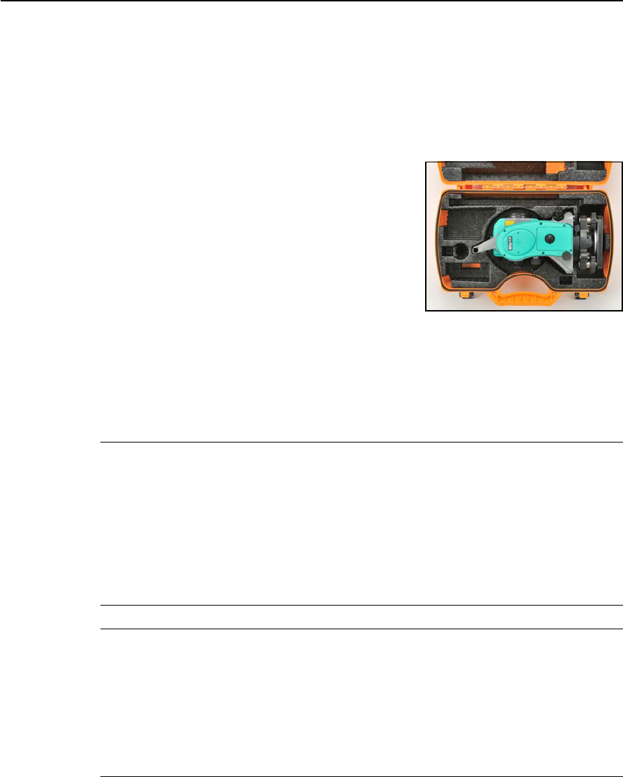
Unpacking and Packing the Instrument
Note – Handle the Nivo series instrument gently to protect it from shocks and
excessive vibration.
Unpacking
To unpack the instrument, grip the carrying handle
and gently remove the instrument from the carrying
case.
Packing
To pack the instrument back into the carrying case,
please refer to the figure on the right.
Charging the Battery Pack
Before charging the battery pack, read the warnings (also listed in the Safety section
at the front of this manual) and the following notes.
CWARNING – Do not damage the rechargeable Lithium-ion battery. A damaged battery can
cause an explosion or fire, and can result in personal injury and/or property damage.
To prevent injury or damage:
– Do not use or charge the battery if it appears to be damaged. Signs of damage include, but
are not limited to, discoloration, warping, and leaking battery fluid.
– Do not expose the battery to fire, high temperature, or direct sunlight.
– Do not immerse the battery in water.
– Do not use or store the battery inside a vehicle during hot weather.
– Do not drop or puncture the battery.
– Do not open the battery or short-circuit its contacts.
CWARNING – Avoid contact with the rechargeable Lithium-ion battery if it appears to be leaking.
Battery fluid is corrosive, and contact with it can result in personal injury and/or property
damage.
To prevent injury or damage:
– If the battery leaks, avoid contact with the battery fluid.
– If battery fluid gets into your eyes, immediately rinse your eyes with clean water and seek
medical attention. Do not rub your eyes!
– If battery fluid gets onto your skin or clothing, immediately use clean water to wash off the
battery fluid.

Total Station Nivo Series Instruction Manual 9
Preparation 2
CWARNING – Charge and use the rechargeable Lithium-ion battery only in strict accordance
with the instructions. Charging or using the battery in unauthorized equipment can cause an
explosion or fire, and can result in personal injury and/or equipment damage.
To prevent injury or damage:
– Do not charge or use the battery if it appears to be damaged or leaking.
– Charge the Lithium-ion battery only in a product that is specified to charge it. Be sure to
follow all instructions that are provided with the battery charger.
– Discontinue charging a battery that gives off extreme heat or a burning odor.
– Use the battery only in equipment that is specified to use it.
– Use the battery only for its intended use and according to the instructions in the product
documentation.
CWARNING – To charge the battery pack, use only the battery charger and AC adapter that are
supplied with the instrument. Do NOT use any other charger or you may cause the battery pack
to catch fire or rupture. The enclosed battery pack cannot be used with other chargers.
CWARNING – Do not cover the battery charger and AC adapter while the battery pack is being
recharged. The charger must be able to dissipate heat adequately. Coverings such as blankets
or clothing can cause the charger to overheat.
CWARNING – Avoid recharging the battery pack in humid or dusty places, in direct sunlight, or
near heat sources. Do not recharge the battery pack when it is wet. If you do, you may receive
electric shocks or burns, or the battery pack may overheat or catch fire.
CWARNING – Although the battery pack has an auto-reset circuit breaker, you should take care
not to short circuit the contacts. Short circuits can cause the battery pack to catch fire or burn
you.
CWARNING – Never burn or heat the battery. Doing so may cause the battery to leak or rupture.
A leaking or ruptured battery can cause serious injury.
CWARNING – Before storing the battery pack or battery charger, cover the contact points with
insulation tape. If you do not cover the contact points, the battery pack or charger may short
circuit, causing fire, burns, or damage to the instrument.
CWARNING – The battery is not itself waterproof. Do not get the battery wet when it is removed
from the instrument. If water seeps into the battery, it may cause a fire or burns.
2 Preparation
10 Total Station Nivo Series Instruction Manual
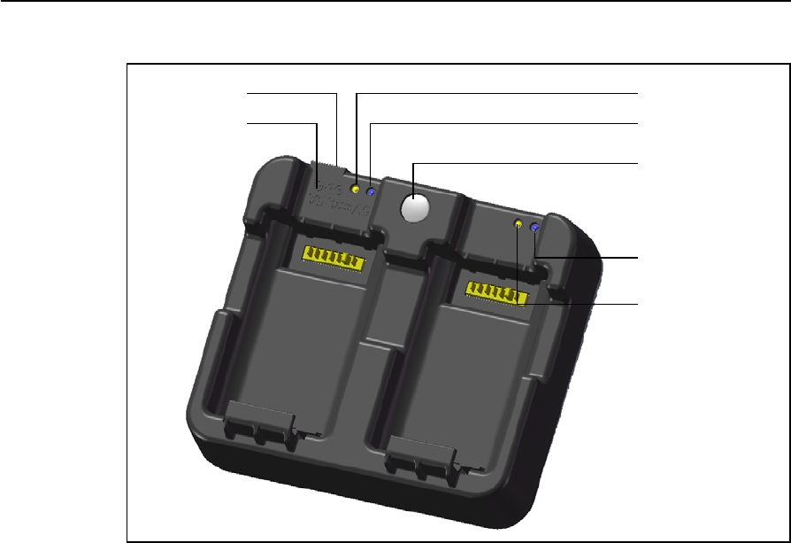
Applying Power
•Plug in the charger to the supplied AC adapter to turn the unit on. The power
input must be 5 V with at least 4 A of current capability. Each battery may take
up to 2 A while charging.
Charging a battery
•Simply slide a battery into either battery slot to begin charging. The adjacent
charge indicator will illuminate yellow when charging is in progress. The
charge indicator will change to green when charging is complete.
•Charger slots are completely independent so a battery may be inserted
regardless of the state of the other battery slot.
•Charging may take 2-4 hours if the battery was normally discharged.
•Charging may take up to 5 hours with a completely drained battery which has
been stored for several months without use.
Charge indicator 0
Calibration
indicator 0
Calibration button
Calibration
indicator 1
Charge indicator 1
Power jack
This will read
5V, 4A
Case
“Top” edge
Battery Slot
0 Battery Slot
1

Total Station Nivo Series Instruction Manual 11
Preparation 2
Conditioning / calibrating a battery
•Battery calibration is necessary about once every 6 months or more often if
desired. Calibration insures the reported battery charge remaining is accurate.
•Hold down the calibration button on the unit and then insert a battery while
holding the calibration button to begin a battery calibration. Only the battery
which was inserted while the button was depressed will begin calibration.
During a battery calibration the battery will be charged, discharged completely,
and then recharged before finishing. Calibration should complete in roughly 17
hours and the charger vents should not be covered during a calibration cycle.
•The blue calibration indicator light(s) will blink slowly (on 1.5 sec, off 2 sec)
while a calibration is in progress and the charge light(s) may be on or off
during the calibration cycle.
•When a calibration cycle is completed, the calibration light will stop blinking
remain on until the corresponding battery is removed.
• If the case temperature begins to get too warm while discharging a battery, the
calibration light blink will blink on for 0.5 sec then off for 3 seconds and the
battery load will be cut in half to prevent further overheating. Battery
calibration will take longer to finish if this occurs. When the case temperature
drops to a safer level battery discharging will return to normal.
•If the case temperature continues to get too hot internally, blinking will become
more rapid and eventually the calibration will be aborted. If an abort occurs,
the calibration light(s) will blink rapidly and battery charging will be re-
enabled.
2 Preparation
12 Total Station Nivo Series Instruction Manual
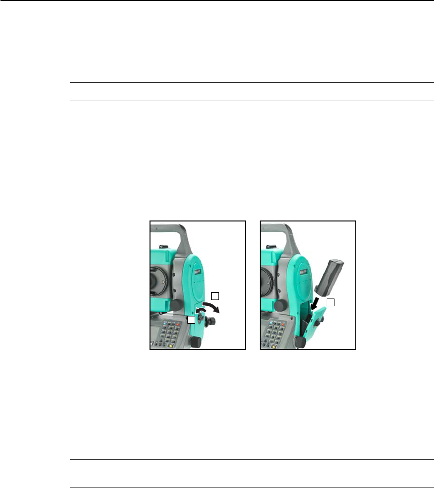
Detaching and Re-Attaching the Battery Pack
Detaching the battery pack
CCAUTION – Avoid touching the contacts on the battery pack.
1. If the instrument is turned on, press [PWR] to turn it off.
2. Turn the battery box release knob counterclockwise, open the battery box cover
and remove the battery pack from the battery box.
Inserting the battery pack
Before inserting the battery pack, clear any dust or other foreign particles from the
battery contacts.
1. Turn the battery box release knob counterclockwise and open the battery box
cover.
2. Put the battery pack into the battery box. Insert the battery pack with the
connectors bottom first, facing inside.
3. Close the battery box cover and turn the knob clockwise until the secure click
sound is heard.
CCAUTION – If the battery box cover is not closed, this could adversely affect the watertightness
of the instrument.
1
2
3

Total Station Nivo Series Instruction Manual 13
Preparation 2
Setting Up the Tripod
CCAUTION – The tops of the tripod ferrules are very sharp. When handling or carrying the
tripod, take care to avoid injuring yourself on the ferrules.
1. Open the tripod legs enough to for the instrument to be stable.
2. Locate the tripod directly over the station point. To check the tripod’s position,
look through the center hole in the tripod head.
3. Firmly press the tripod ferrules into the ground.
4. Level the top surface of the tripod head.
5. Securely fasten the thumb screws on the tripod legs.
6. Place the instrument on the tripod head.
7. Insert the tripod mounting screw into the center hole of the base plate of the
instrument.
8. Tighten the tripod mounting screw.
Note – Do not carry the instrument while it is attached to a tripod.
Centering
When you center the instrument, you align its central axis precisely over the station
point. To center the instrument, you can either use the optical plummet or a plumb
bob.
Centering using the optical plummet
Note – If you require high accuracy, check and adjust the optical plummet before you
center the instrument. For detailed instructions, see Checking and Adjusting the
Optical/Laser Plummet, page 136.
To center the instrument using the optical plummet:
1. Set up the instrument on the tripod. For detailed instructions, see Setting Up the
Tripod, page 13.
2. While looking through the optical plummet, align the
reticle with the station point. To do this, turn the leveling
screws until the center mark of the reticle is directly
over the image of the station point.
3. While supporting the tripod head with one hand, loosen
the tripod leg clamps and adjust the lengths of the legs
until the air bubble is in the center of the circular level.
4. Tighten the tripod leg clamps.

2 Preparation
14 Total Station Nivo Series Instruction Manual
5. Use the electronic level to level the instrument. For detailed instructions, see
Leveling, page 15.
6. Look through the optical plummet to check that the image of the station point is
still in the center of the reticle mark.
7. If the station point is off center, do one of the following:
–If the station point is slightly off center, loosen the tripod mounting screw
and then center the instrument on the tripod. Use only direct movement to
center the instrument. Do not rotate it.
When the instrument is centered, tighten the mounting screw.
–If the displacement of the station point is major, repeat this procedure
from Step 2.
Centering using the laser plummet
Note – Do NOT look into the laser directly.
Note – If you require high accuracy, check and adjust the laser plummet before you
center the instrument. For detailed instructions, see Checking and Adjusting the
Optical/Laser Plummet, page 136.
1. Set up the instrument on the tripod. For detailed instructions, see Setting Up the
Tripod, page 13.
2. Turn on the laser plummet. See Laser plummet ON/OFF, page 36.
3. Align the laser pointer to the station point. To do this, turn the leveling screws
until the laser pointer is over the station point.
4. While supporting the tripod head with one hand, loosen the tripod leg clamps
and adjust the lengths or the legs until the air bubble is the center of the circular
level.
5. Tighten the tripod leg clamps.
6. Use the electronic level to level the instrument. For detailed instructions, see
Leveling, page 15.
7. Check the laser pointer is over the station point.
8. If the station point is off center, do one of the following:
–If the station point is slightly off center, loosen the tripod mounting screw
and then center the instrument on the tripod. Use only direct movement to
center the instrument. Do not rotate it.
–When the instrument is centered, tighten the mounting screw.
–If the displacement of the station point is major, repeat this procedure
from Step 2
Total Station Nivo Series Instruction Manual 15
Preparation 2
Centering using a plumb bob
1. Set up the instrument on the tripod. For detailed instructions, see Setting Up the
Tripod, page 13.
2. Hang the plumb line on the hook of the tripod mounting screw.
3. Adjust the length of the plumb line so that the tip of the plumb bob is at the
height of the station point.
4. Loosen the tripod mounting screw slightly.
5. Using both hands to support the outer side of the tribrach, carefully slide the
instrument about on the tripod head until the tip of the plumb bob is positioned
over the exact center of the station point.
Note – To confirm that the instrument is precisely aligned, check its position from two
directions at right angles to each other.
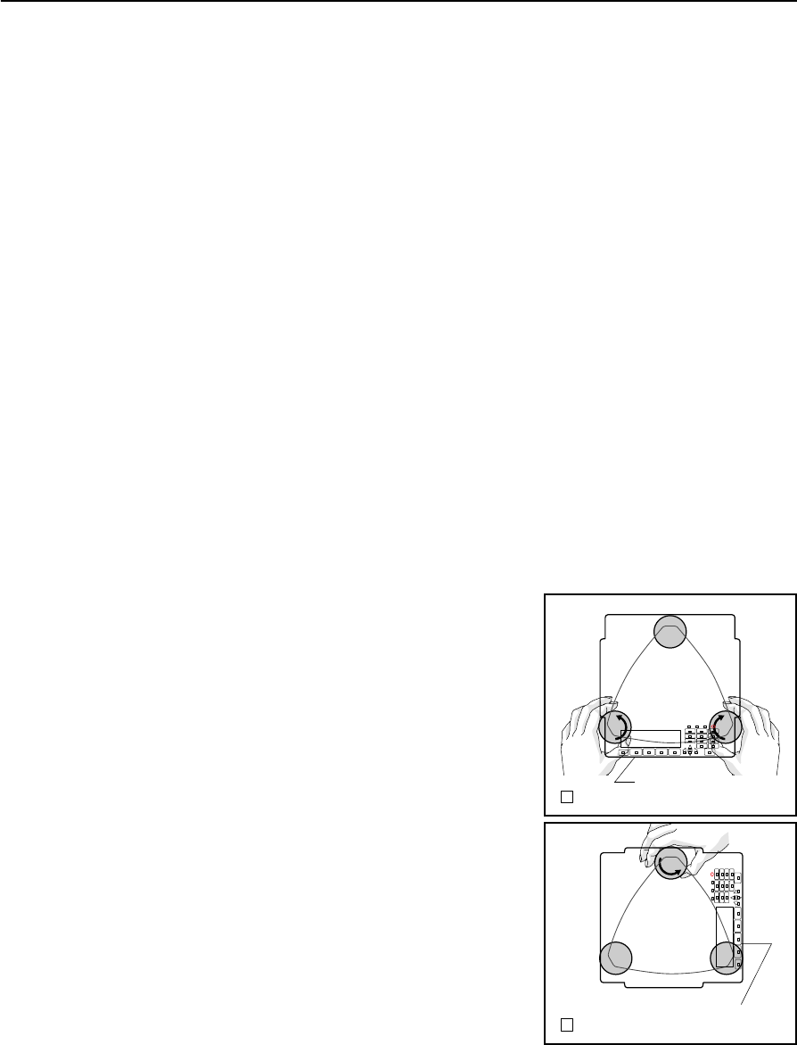
Leveling
When you level the instrument, you make the vertical axis of the instrument exactly
vertical. To level the instrument, use the electronic level. In the leveling work, always
set the instrument in face 1 direction (please refer to the Fig.1.1 in page 3).
To level the instrument:
1. Move the bubble into the circle drawn on the
circular level and then turn on the power.
2. Rotate the alidade until the bottom edge of
the keyboard panel is parallel to the two of
the leveling screws (B and C).
3. Use leveling screws B and C to move the
bubble into the center of the electronic level.
4. Rotate the alidade approximately 90°.
5. Use leveling screw A to move the bubble into
the center of the electronic level.
6. Repeat Step 1 through Step 5 to center the
bubble in both positions.
7. Rotate the alidade 180°.
8. If the bubble in the electronic level remains
centered, the instrument is level. If the
bubble moves off center, adjust the electronic
level. For detailed instructions, see Adjusting
the Electronic Level, page 136.
B C
A
1
Bottom edge of
the keyboard panel
CB
A
2
Bottom edge of
the keyboard panel
2 Preparation
16 Total Station Nivo Series Instruction Manual
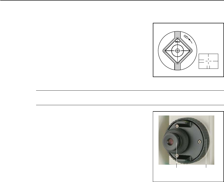
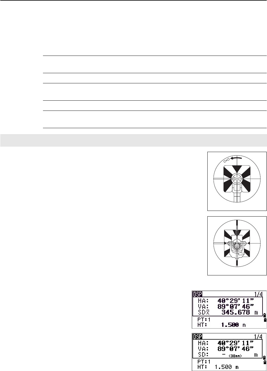
Sighting
When you sight the instrument, you aim the
telescope at the target, bring the target image into
focus, and align the image with the center
crosshairs of the reticle.
To sight the instrument:
1. Adjust the diopter:
a. Aim the telescope at a blank area, such
as the sky or a piece of paper.
CWARNING – Never look at the sun through the telescope. If you do, you may damage or lose
your eyesight.
b. Looking through the eyepiece, rotate the
diopter ring until the reticle crosshairs
are in sharp focus.
2. Eliminate parallax:
a. Aim the telescope at the target image.
b. Rotate the focusing ring until the target
image is in sharp focus on the reticle
crosshairs.
c. Move your eye vertically and laterally to
check whether the target image moves
relative to the reticle crosshairs.
If the target image does not move, there is no parallax.
d. If the target image does move, rotate the telescope focusing ring. Then
repeat from Step c.
3. Rotate the tangent screw:
–The final turn of the tangent screw should be in a clockwise directions, to
align the target accurately on the center crosshairs.
Center
crosshairs
Diopter ring Telescope focusing
ring
Total Station Nivo Series Instruction Manual 17
Preparation 2
Setting the Measurement Mode and Preparing the Target
The Nivo series has two measurement modes: Prism mode (Prism) and
Reflectorless mode (N-Prism). These modes can be changed at any time by holding
down the [MSR1] or [MSR2] key for one second. For more information, see Measurement
settings, page 48.
To set the measurement mode depending on the target you want to measure, see the
following table.
In some cases, you can measure another target that is not appropriate to the set
measurement mode.
Note – The Nivo series is Laser Class 1 in the measurement function, and Laser Class
2 in the Laser pointer function.
Don’t sight the Prism when the Laser Pointer is on.
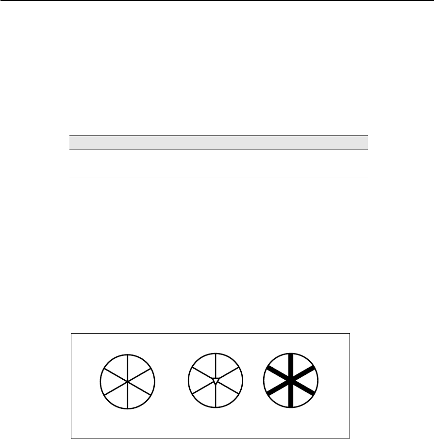
Measurement with a prism
Do not use a prism with scratches, a dirty surface, or a chipped center. Prisms with
thin edges are recommended.
As the Nivo series is extremely sensitive, multiple reflections on the prism surface
can sometimes cause a significant loss in accuracy.
To maintain the accuracy of your measurements:
Target Target setting
Prism, reflector sheet Prism (Prism mode)
Other (reflective materials) N-Prism (Reflectorless mode)
thin edges chipped center thick edges
✓✕✕
2 Preparation
18 Total Station Nivo Series Instruction Manual
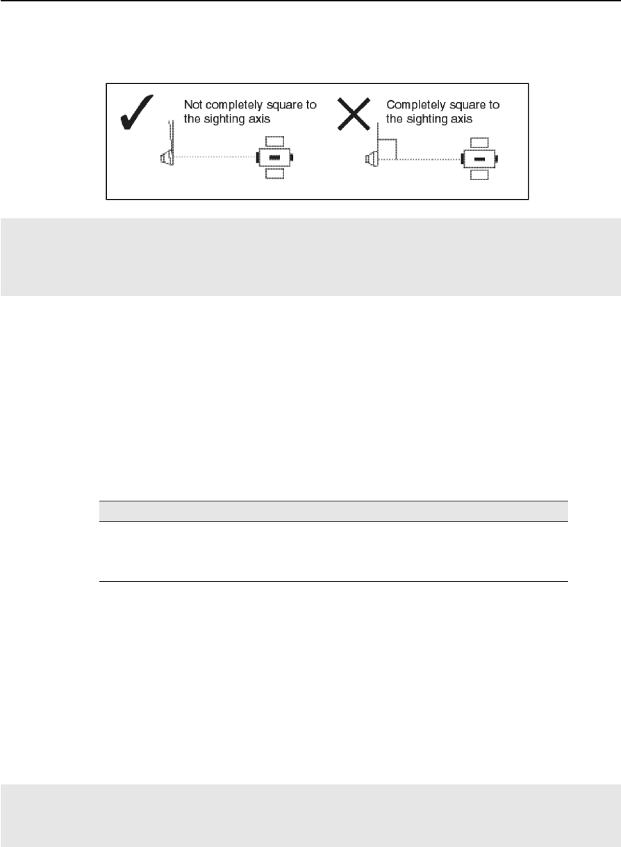
•When measuring a short distance, incline the prism slightly so that the EDM
can ignore unnecessary reflections on the prism surface, as shown below.
Measurement in Reflectorless mode
The intensity of the reflection from the target determines the distance the Nivo series
can measure in this mode. The color and condition of the target surface also affect the
measurable distance, even if the targeted objects are the same. Some less-reflective
targets may not be measured.
The following table describes some examples of targets and approximate measureable
distances.
Measurable distances may be shorter or measurement intervals may be longer in the
following cases:
•the angle of the laser against the target is small
•the surface of the target is wet
In direct sunlight, the measurable distance may be shorter. In this case, try to throw a
shadow on the target.
Targets with completely flat surfaces, such as mirrors, cannot be measured unless the
beam and the target are perpendicular to each other.
Hold the prism securely in place and do not move while taking measurements.
In Prism mode, in order to avoid false measurements on objects other than the prism or reflector-sheet, targets
that are less reflective than the prism or reflector sheet are not measured. Even if you start a measurement,
measured values are not displayed. To measure less reflective objects, use the N-prism (reflectorless) mode
Target You can measure approximately...
Traffic signs, reflectors 500 meters (1640 feet)
Paper (white), veneer (new) 300 meters (990 feet)
wall (brightly painted), brick 100 to 200 meters (330 to 660 feet)
Make sure there are no obstacles between the instrument and the target when taking measurents.
When you need to take measurements across a road or a place where vehicles or other objects are frequently
moving, take several measurements to a target for the best result.
Total Station Nivo Series Instruction Manual 19
Preparation 2
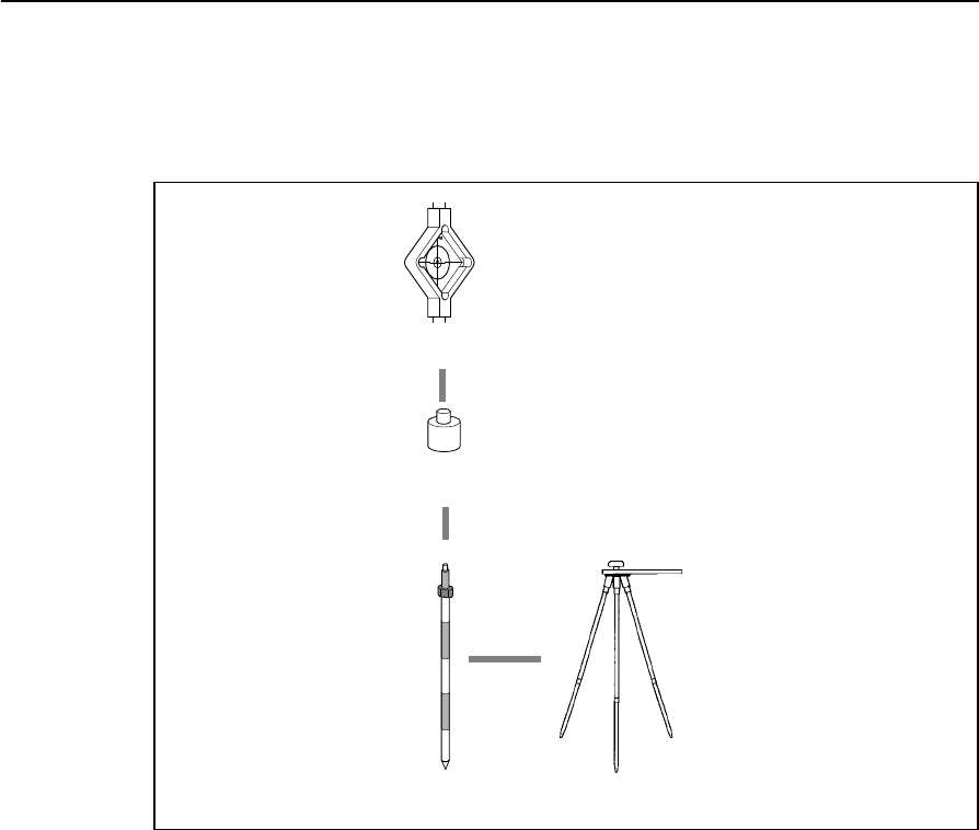
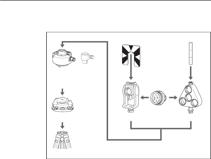
Preparing the Reflector Sheet
The reflector sheet can be used for measurements in Prism mode. Assemble the
reflector sheet as shown below.
Reflector
sheet
Mini prism
adapter
Telescopic
prism pole Prism pole
tripod type PPS
2 Preparation
20 Total Station Nivo Series Instruction Manual
Setting Up the Prism Reflector
1. Assemble the prism reflector as shown below.
2. Adjust the height of the tribrach adaptor (see page 21).
3. If necessary, change the direction of the prism (see page 21).
4. Set the prism constant (see page 21).
5. If you are using a single prism holder, set the position of the target plate (see
page 22).
Detailed instructions for Step 2 through Step 5 are provided on the following pages.
Note – Nivo series must be used with the Tribrach W30 or W30b.
Tribrach
Tribrach
Tripod
Target plate for single prism
Tiltable single
prism holder
Prism C
Ta r g et pol e
Triple prism holder
Height adjust-
ment adapter
is not used.
W30/W30b
adapter 15
Total Station Nivo Series Instruction Manual 21
Preparation 2
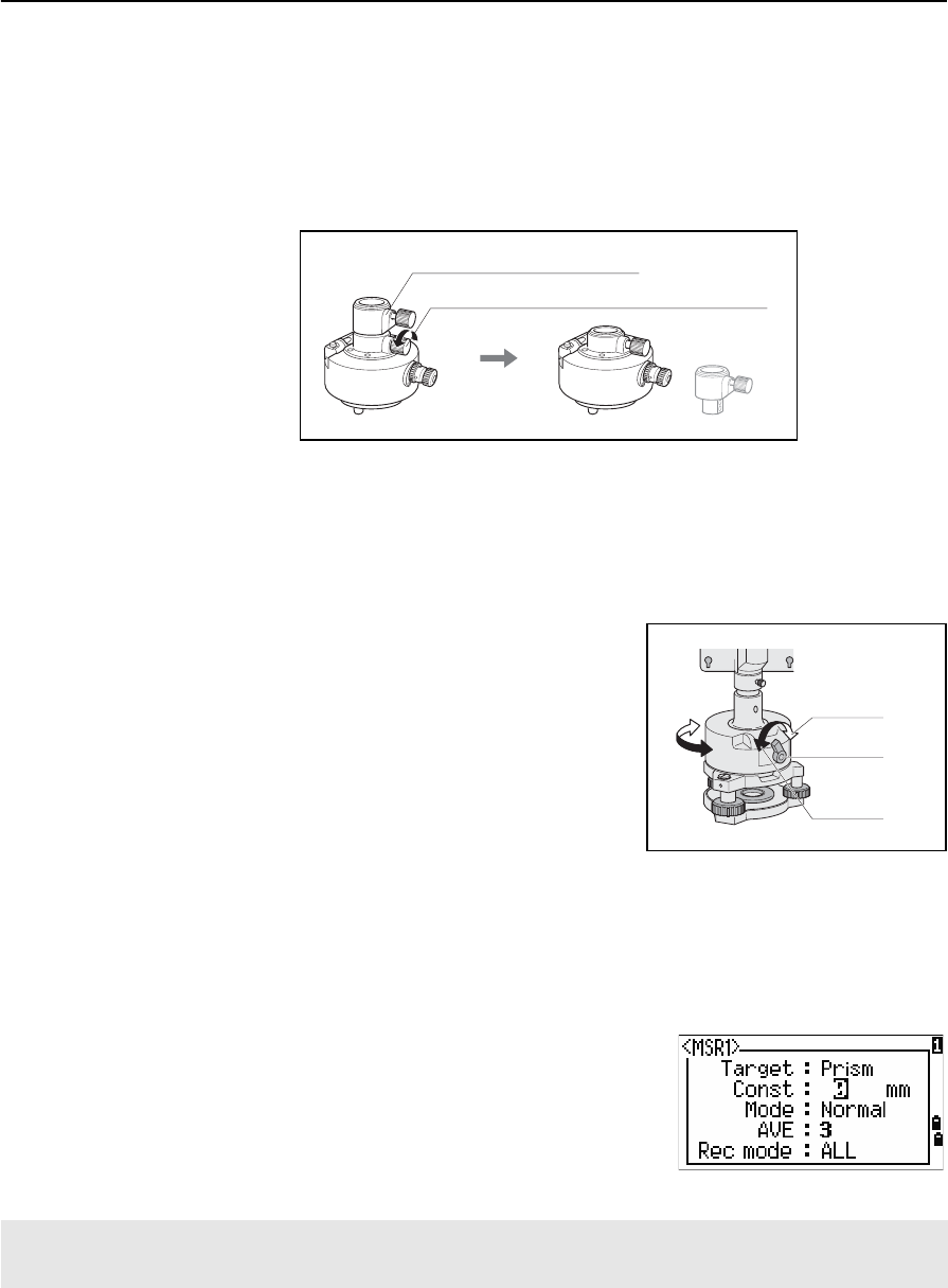
Adjusting the height of the tribrach adapter
The tribrach adapter has a height adjustment adapter. To use the prism reflector with a
Nivo series instrument, remove the height adjustment adapter as shown in the Figure
below.
The height adjustment adapter will be used with other Nikon Total Stations.
Changing the direction of the prism
The prism mounted on the tribrach adapter can be rotated to face in any direction.
To change the direction of the prism:
1. Release the rotation clamp. To do this, turn
the clamp lever counterclockwise.
2. Turn the upper plate of the tribrach adapter
until the prism is facing in the required
direction.
3. Fasten the rotation clamp. To do this, turn the
clamp lever clockwise.
Setting the prism constant
1. Attach the prism to the single prism holder or triple prism holder.
BTip – To use a triple prism holder as a single prism holder, attach the prism to the center thread
of the prism holder.
2. Set the prism constant. To do this, hold down
[MSR1] or [MSR2] for one second. For more
information, see Measurement settings, page 48.
Note – The prism constant of a Nikon prism is always
0, whether it is attached to a single prism holder or a
triple prism holder.
BTip – When you use the prism at a short distance, set the prism at a slight angle to the sighting
axis, rather than completely square.
If your prism constant is not 0 mm, then directly enter the prism constant value in the Const field. For example,
if your prism constant is 30 mm, enter 30mm in the Const field on the instrument.
Height adjustment adapter
Height adjustment adapter clamp screw
Clamp
Clamp lever
Unclamp

2 Preparation
22 Total Station Nivo Series Instruction Manual
Setting the position of the target plate
If using a single prism, make sure that the target plate is aligned with the tribrach
adapter and the prism.
To set the position of the target plate:
1. Use the two set screws supplied to attach the
target plate to the single prism holder.
2. Move the target plate within the screw holes
until the apex of the wedge pattern is aligned
with the vertical axis of the prism and the
tribrach adapter.
Center on axis

CHAPTER
3
Total Station Nivo Series Instruction Manual 23
Getting Started 3
In this chapter:
QTurning the Instrument On and Off
QChanging Regional Configuration Pre-sets
QDisplay and Key Functions
QList Display
QInputting Data
QJobs
QMeasuring Distances
3 Getting Started
24 Total Station Nivo Series Instruction Manual
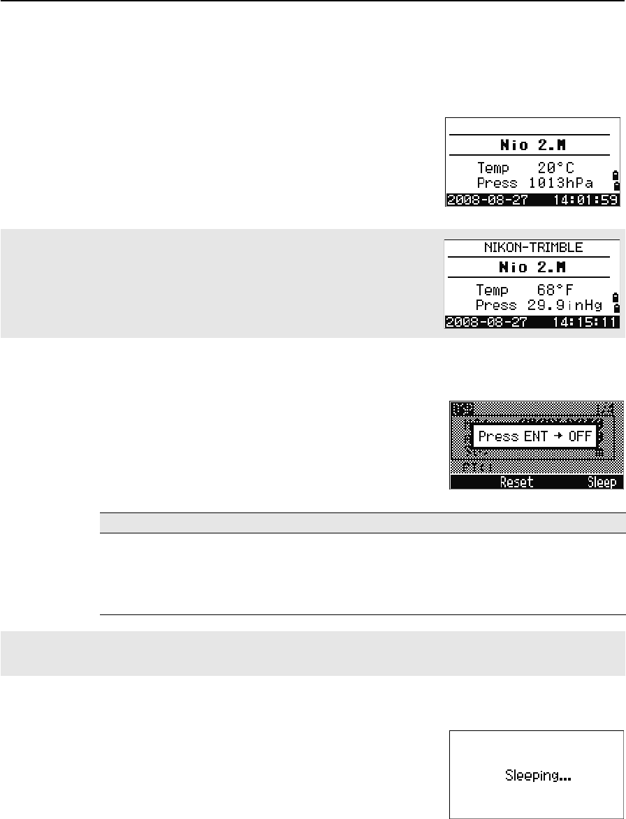
Turning the Instrument On and Off
Turning on the instrument
1. To turn on the instrument, press [PWR]. The start-
up screen appears. It shows the model name,
current temperature, pressure, date, and time.
The display automatically changes to the
electronic level after 2 seconds.
Turning off the instrument
To enter the power-off process, press [PWR] and [ENT].
Then do one of the following:
Sleep mode
If you press the Sleep softkey in the Press [ENT] →
OFF screen, or enable the Power Save setting (see
Power saving, page 110), the instrument goes into
sleep mode.
When the instrument is in sleep mode, it wakes up if
any of the following occurs:
•You press a key
•The instrument receives a remote control command
If you have entered your name or your company’s name in the Owner’s detail
field, the text from this field appears on the start-up screen. To set the Owner’s
detail field, go to MENU > Settings > Others. For more
information, see page 113.
Press ... To ...
[ENT] again turn off the instrument
the Reset softkey reboot the program and re-start the instrument
the Sleep softkey put the instrument into power-saving mode
[ESC] cancel the power-off process and return to the previous screen
If you press the Reset softkey, the software is rebooted and the Basic Measurement Screen (BMS) appears
without an open job.
Total Station Nivo Series Instruction Manual 25
Getting Started 3
•You rotate the alidade
•You tilt the telescope
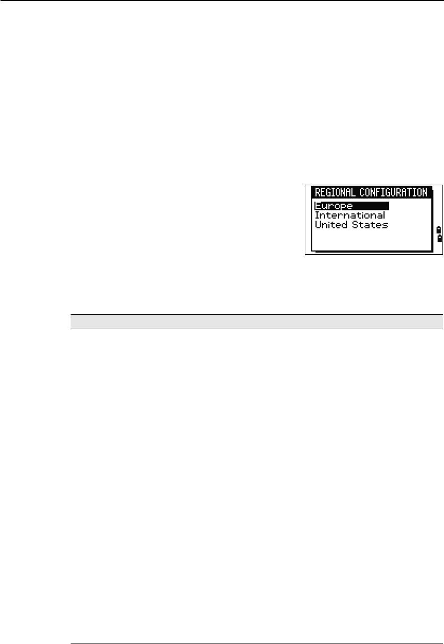
Changing Regional Configuration Pre-sets
To provide easier configuration for common regional settings, you can quickly
configure the Nikon total station to a pre-set combination of default regional settings.
The Regional Configuration screen appears only after the language configuration is
complete, the instrument has rebooted.
1. Follow the steps in Language, page 113.
Once the instrument rebooted, the Regional
Configuration screen appears.
2. Press [^] or [v] to highlight the required
regional settings and then press [ENT].
3. If you do not want to change the current
settings, press [ESC] and quit. The instrument
will continue to use the last configured settings that were configured.
The settings affected by the Regional Configuration screen are:
Category Setting Europe International United States
Angle VA zero Zenith Zenith Zenith
Resolution 1"(See note) 1"(See note) 1"(See note)
HA Azimuth Azimuth Azimuth
Distance Scale 1.000000 1.000000 1.000000
T-P corr. On On On
Sea Level Off Off Off
C&R corr. 0.132 0.132 0.132
Coordinates Order ENZ ENZ NEZ
Label ENZ ENZ NEZ
AZ zero North North North
Power Save Main Unit Off Off Off
EDM Unit Off Off Off
Sleep 5 minutes 5 minutes 5 minutes
Communication Ext. Comm Nikon Nikon Nikon
Baud 4800 4800 4800
Length 8 8 8
Parity None None None
Stop bit 1 1 1
Stakeout Add PT 1000 1000 1000
Units Angle GON DEG DEG
Distance meters meters US-ft
3 Getting Started
26 Total Station Nivo Series Instruction Manual
The default regional configuration pre-set is “United States” settings. For more
information, see Settings, page 108.
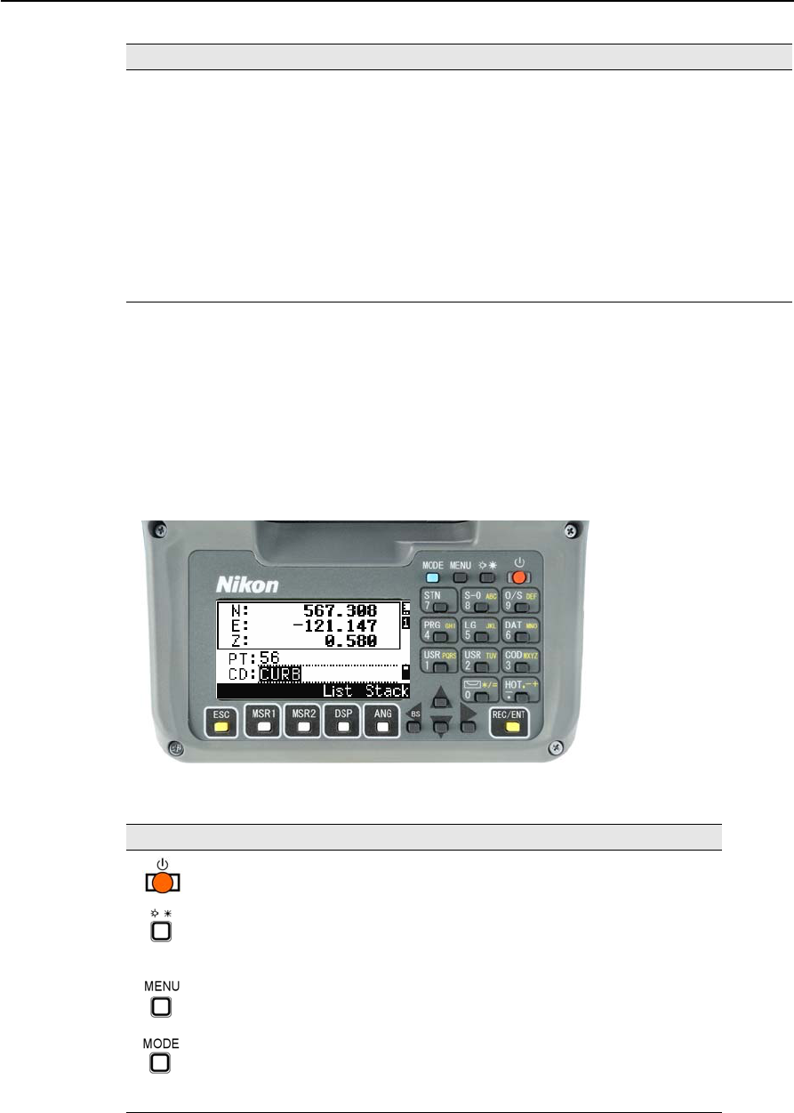
Display and Key Functions
The following figure shows the keys on the Nivo series instrument keyboard and the
LCD display.
The functions of the Nivo keys are as follows.
Temp °C °C °F
Press mm Hg mm Hg In Hg
Rec Store DB RAW&XYZ RAW&XYZ RAW&XYZ
Data Rec Internal Internal Internal
Others XYZ disp Fast Fast Fast
2nd Unit None None None
Split ST No No No
CD Input <ABC> <ABC> <ABC>
Owner’s Detail Blank Blank Blank
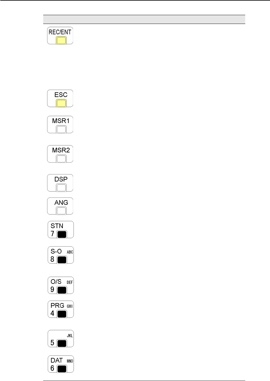
Key Function Details
Turns the instrument on or off. page 24
(Illumination key)
Provides access to the switch window.
Turns on/off the LCD backlight if held down for one second.
page 30
Displays the MENU screen. page 91
Changes the key input mode between alphanumeric and
numeric if pressed when you are in a PT or CD field.
Activates Qcode mode if pressed when you are In the
Basic Measurement Screen (BMS).
page 32
Category Setting Europe International United States
Total Station Nivo Series Instruction Manual 27
Getting Started 3
Records measured data, moves on to the next screen, or
confirms and accepts the entered data in input mode.
You have the option to record the measurement as a CP
record instead of an SS record, if you hold this key down
for one second in the Basic Measurement Screen (BMS).
The instrument outputs the current measurement data (PT,
HA, VA, and SD) on the COM port if you press this key in
the BMS or in a Stakeout observation screen. (The Data
Rec settings must be set to COM.)
page 81
Returns to the previous screen.
In numeric or alphanumeric mode, deletes input.
Starts distance measurement, using the measure mode
settings for the [MSR1] key.
Displays measurement mode settings, if held down for one
second.
page 47
Starts distance measurement, using the measure mode
settings for the [MSR2] key.
Displays measurement mode settings, if held down for one
second.
page 47
Moves to the next available display screen.
Changes the fields that appear on the DSP1, DSP2, and
DSP3 screens, if held down for one second.
page 49
Displays the Angle menu. page 52
Displays the Station Setup menu.
In numeric mode, enters 7. In alphanumeric mode, enters
7.
page 53
Displays the Stakeout menu.
Shows stakeout settings, if held down for one second.
In numeric mode, enters 8. In alphanumeric mode, enters
A, B, C, or 8.
page 64
Displays the Offset Point Measurement menu.
In numeric mode, enters 9. In alphanumeric mode, enters
D, E, F, or 9.
page 83
Displays the Programs menu, which contains additional
measuring programs.
In numeric mode, enters 4. In alphanumeric mode, enters
G, H, I, or 4.
page 71
In numeric mode, enters 5. In alphanumeric mode, enters
J, K, L, or 5.
Displays RAW, XYZ, or STN data, depending on your
setting.
In numeric mode, enters 6. In alphanumeric mode, enters
M, N, O, or 6.
page 38
Key Function Details
3 Getting Started
28 Total Station Nivo Series Instruction Manual
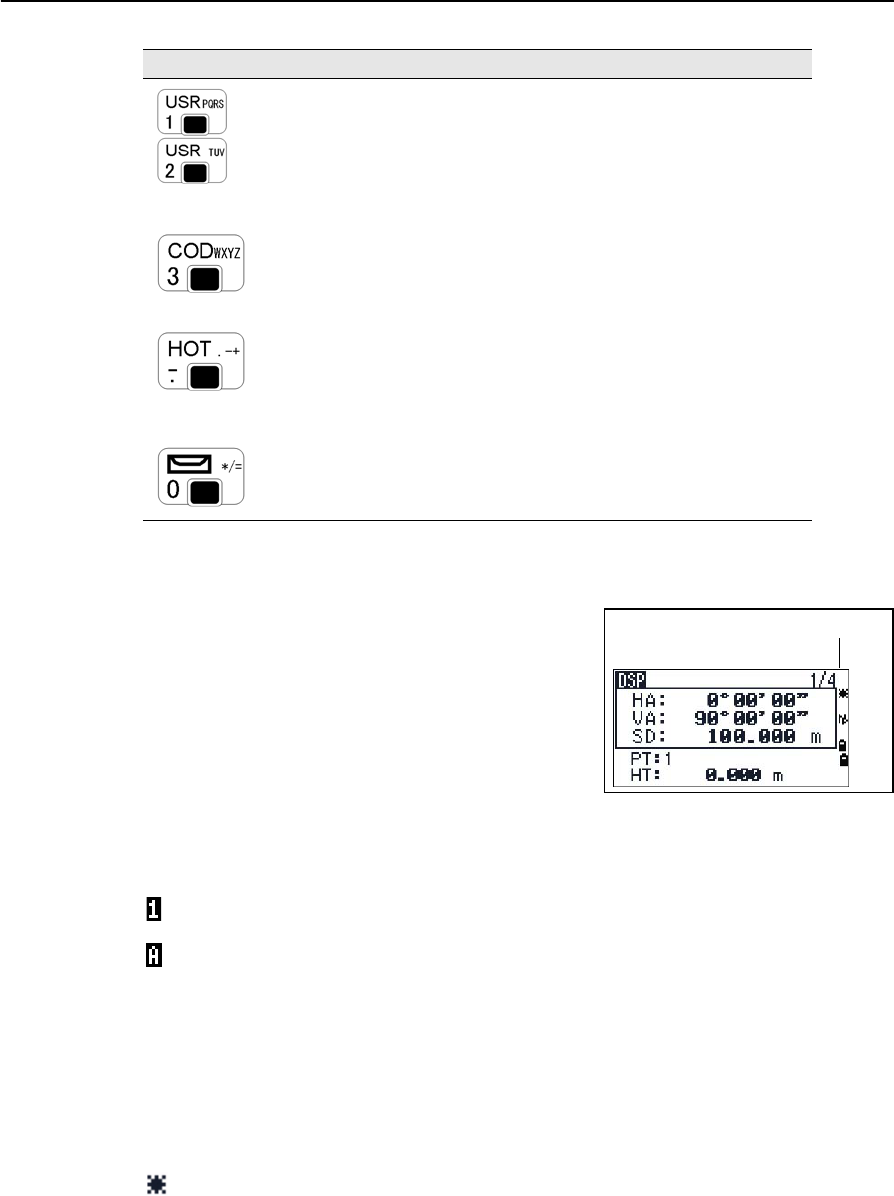
Status bar
The status bar appears on the right side of every
screen. It contains icons that indicate the status of
various system functions.
Input mode indicator
The Input mode indicator only appears when you are entering points or coordinates. It
shows the data input mode:
Laser pointer indicator
The icon appears while turning on the laser pointer. When the icon is displayed on the
screen, the emitting power is laser class 2.
Executes the function that is assigned to the [USR1] key.
In numeric mode, enters 1. In alphanumeric mode, enters
P, Q, R, S, or 1.
Executes the function that is assigned to the [USR2] key.
In numeric mode, enters 2. In alphanumeric mode, enters
T, U , V, or 2.
page 37
Opens a window where you can enter a code. The default
code value is the last code entered.
In numeric mode, enters 3. In alphanumeric mode, enters
W, X, Y, Z, or 3.
page 33
Displays the (HOT) menu, which includes Height of Target,
Temp-Press, Target, Note recording, and Default PT
settings.
In numeric mode, enters – (minus). In alphanumeric mode,
enters . (period), – (minus), or + (plus).
page 34
Displays the Bubble indicator.
In numeric mode, enters 0. In alphanumeric mode, enters *,
/, =, (a space), or 0.
page 36
Input mode is numeric. Press a key on the number pad to enter the number printed on
the key.
Input mode is alphabetic. Press a key on the number pad to enter the first letter printed
beside the key. Press the key repeatedly to cycle through all the letters assigned to that
key.
For example, to enter the letter O in alphabetic mode, press [5] three times.
Laser pointer ON.
(None) Laser pointer OFF.
Key Function Details
Status bar
Total Station Nivo Series Instruction Manual 29
Getting Started 3
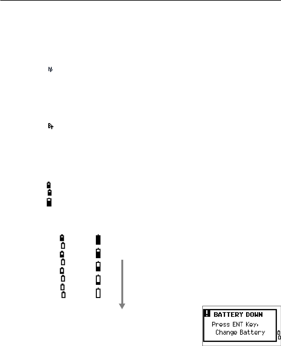
EDM measurement status
When you are taking measurements, the EDM measurement status shows the mode
that is being used.
When you display observation data, the EDM measurement status shows the mode
that was used when the data was collected.
Communication port status
(This is only available when the optional Bluetooth is installed. See Optional
Bluetooth function, page 129.)
Battery indicator
Shows each voltage level of the right and left internal batteries individually. When the
external battery is connected with the instrument, its voltage is shown.
If the battery level becomes critically low, the message
on the right appears:
Reflectorless mode
Bluetooth enabled
Internal batteries (above: Left battery, below: Right battery)
External battery
Internal
battery
External
battery
Battery level indication
: Battery low
3 Getting Started
30 Total Station Nivo Series Instruction Manual
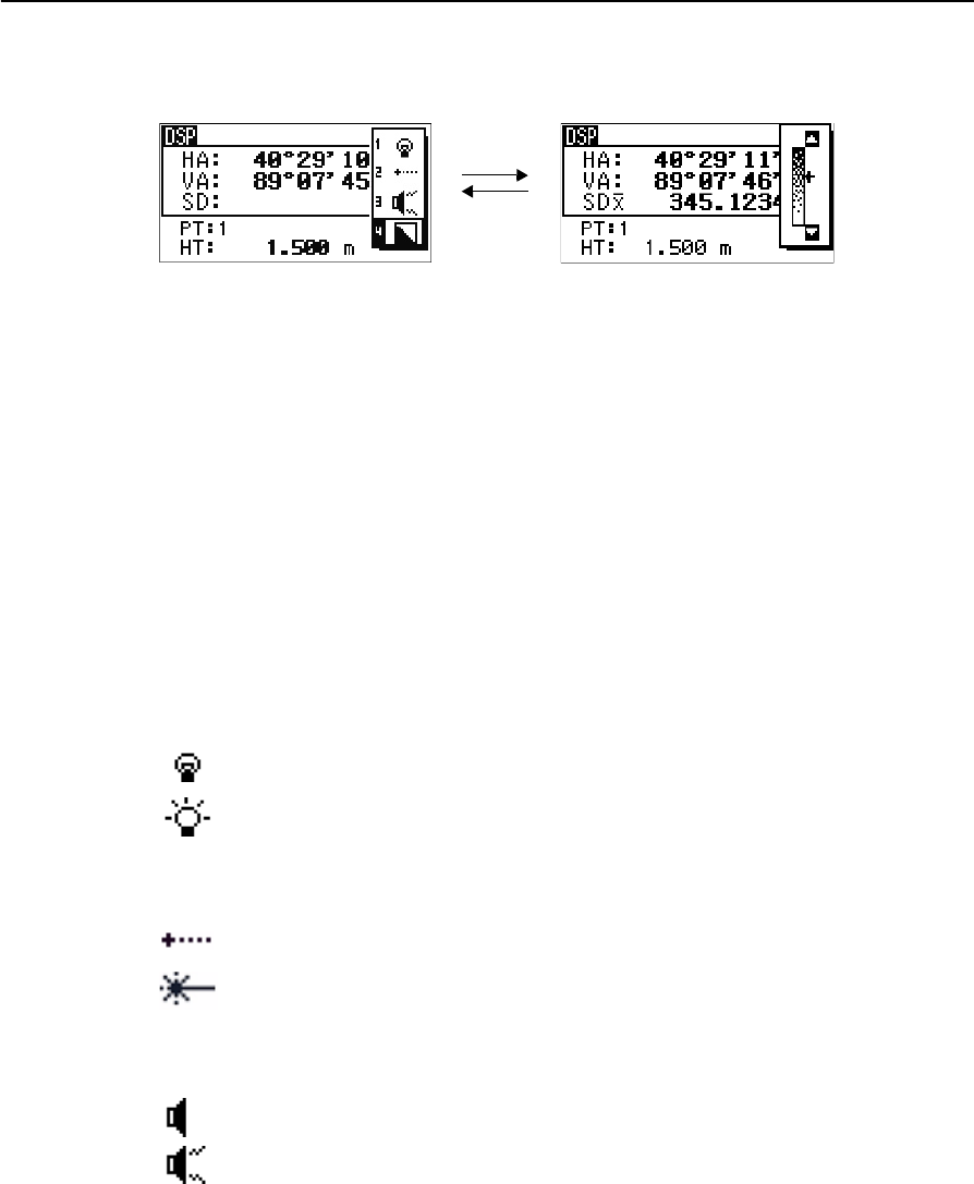
LCD backlight, Laser pointer, Beep sound and Contrast adjustment
To turn on/off the 1. LCD backlight, 2. laser pointer or 3. beep sound, and to do the
4. contrast adjustment, press the illumination key and open the switch set up window
shown above.
Holding down the illumination key for one second also turns on/off the LCD
backlight.
•To turn on/off each function, press [ENT] when the option 1, 2, 3 or 4 is selected
or directly press [1],[2],[3] or [4] numeric key.
•Press [^] or [v] to move the cursor up and down.
•In the contrast adjustment window, use [^] or [v] to adjust the contrast.
To close the window, press [ESC].
1. LCD backlight
2. Laser pointer
3. Sound
[ENT] /[4]
[ESC]
<Switch set up window > <Contrast adjustment window>
LCD backlight is OFF
LCD backlight is ON
Laser pointer is OFF
Laser pointer is ON
Sound is OFF
Sound is ON
Total Station Nivo Series Instruction Manual 31
Getting Started 3
[DSP] key
Use the key to change the current display screen or to change display settings.
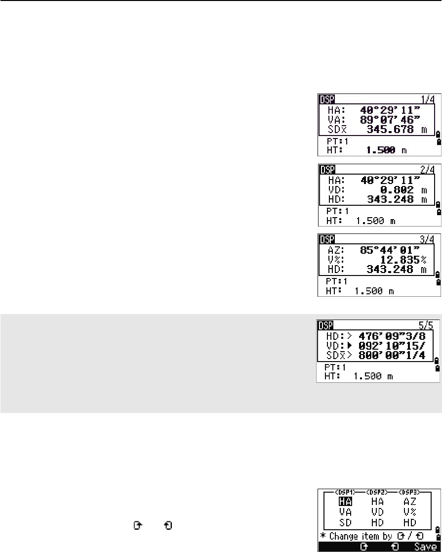
Switching between display screens
When several display screens are available, the DSP
indicator appears at the top left of the screen, and the
screen indicator (for example, 1/4) appears at the top
right.
To move to the next available screen, press [DSP].
For example, if the DSP2 screen is currently displayed,
press [DSP] to move to the DSP3 screen. The screen
indicator changes from 2/4 to 3/4.
Customizing items in the Basic Measurement Screen (BMS)
To customize the items that are displayed on the DSP1, DSP2, and DSP3 screens:
1. Hold down [DSP] for one second.
2. Use the arrow keys [^],[v],[<], and [>] to highlight
the item that you want to change.
3. Use the and softkeys to scroll through the
list of items that can be displayed for this item.
The items that you can choose from are HA, AZ,
HL, VA, V%, SD, VD, HD, Z, and (none).
When the secondary distance unit is set, an additional screen is available. It
shows the HD, VD, and SD values. For information on setting the secondary
distance unit, see page 112.
The smallest unit of display for distances measured in feet-and-inches is 1/16
in. Smaller units are impractical in the field. When the actual value is greater
than 99999'11''15/16, the “>” symbol is shown. If the actual distance is less
than -9999'11''15/16, the “`” (solid triangle) symbol is shown. This does not
affect calculations. The precise value is used internally in all cases.
3 Getting Started
32 Total Station Nivo Series Instruction Manual
4. To save your changes, press the Save softkey. Alternatively, highlight the last
item for DSP3 and press [ENT]. The DSP screens show the items you have
selected.
[MODE] key
Use the [MODE] key to change the keyboard mode for the current screen.
Changing input mode while entering points or codes
When the cursor is in a point (PT) or code (CD) field,
press [MODE] to change the input mode between
alphanumeric (A) and numeric (1).
The input mode indicator in the status bar changes to
show the current input mode.
Except for the (none) item, you cannot display the same item on more than one line of the same screen.
The items displayed in the DSP1, DSP2, DSP3, and DSP4 screens are also used in the corresponding Stakeout
screens (SO2, SO3, SO4, and SO5).
You can also customize the displayed items in Stakeout.
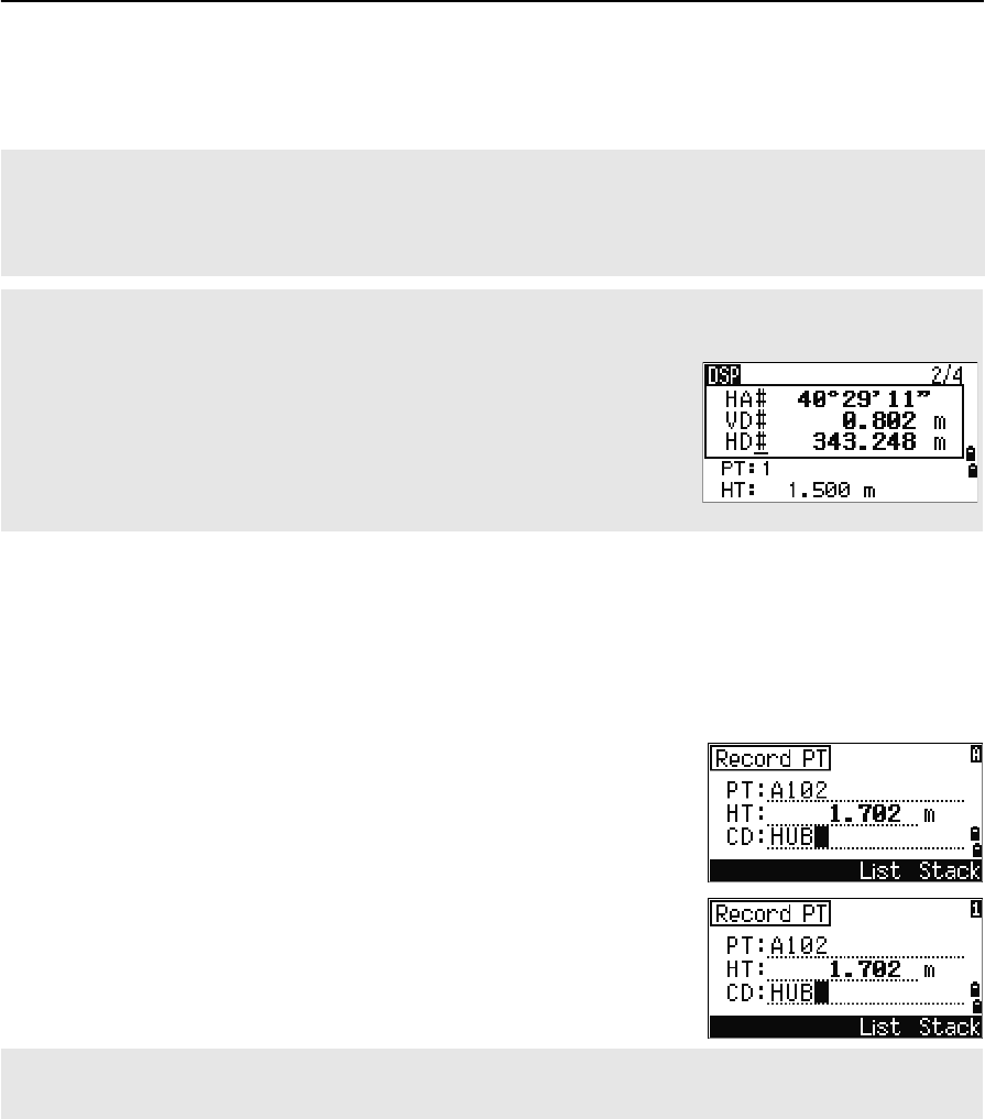
Header characters
The following header characters can be used in DSP screens:
• A colon (:) indicates that tilt correction is applied to the value.
• A hash symbol (#) indicates that tilt correction is off.
• An underscore (_) under the tilt correction character indicates that Sea
Level Correction or Scale factor is applied.
When the cursor is in a height (HT) field, only numeric input mode is available. Pressing [MODE] has no effect
when the cursor is in a HT field.
Total Station Nivo Series Instruction Manual 33
Getting Started 3
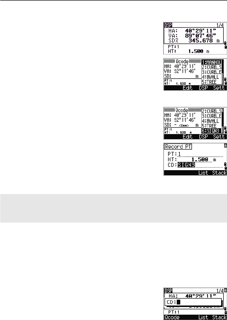
Quick code measurement mode
1. To activate Quick code measurement mode,
press [MODE] in the BMS.
The PT field shows the default point name.
2. Press any numeric key ([0] through [9]) to start
measuring and recording points.
A list of the numeric keys and their assigned
feature codes appears on the right side of the
screen.
For example, when you press [6], the code
assigned to 6 is selected, and the instrument
starts a measurement.
3. If you have set the record mode to Confirm (see
Measurement settings, page 48), the Record PT
screen appears after each measurement.
Do one of the following:
–To record the point, press [ENT].
–To return to the BMS, press [ESC].
4. To return to the BMS from the Qcode screen, press [MODE] or [ESC].
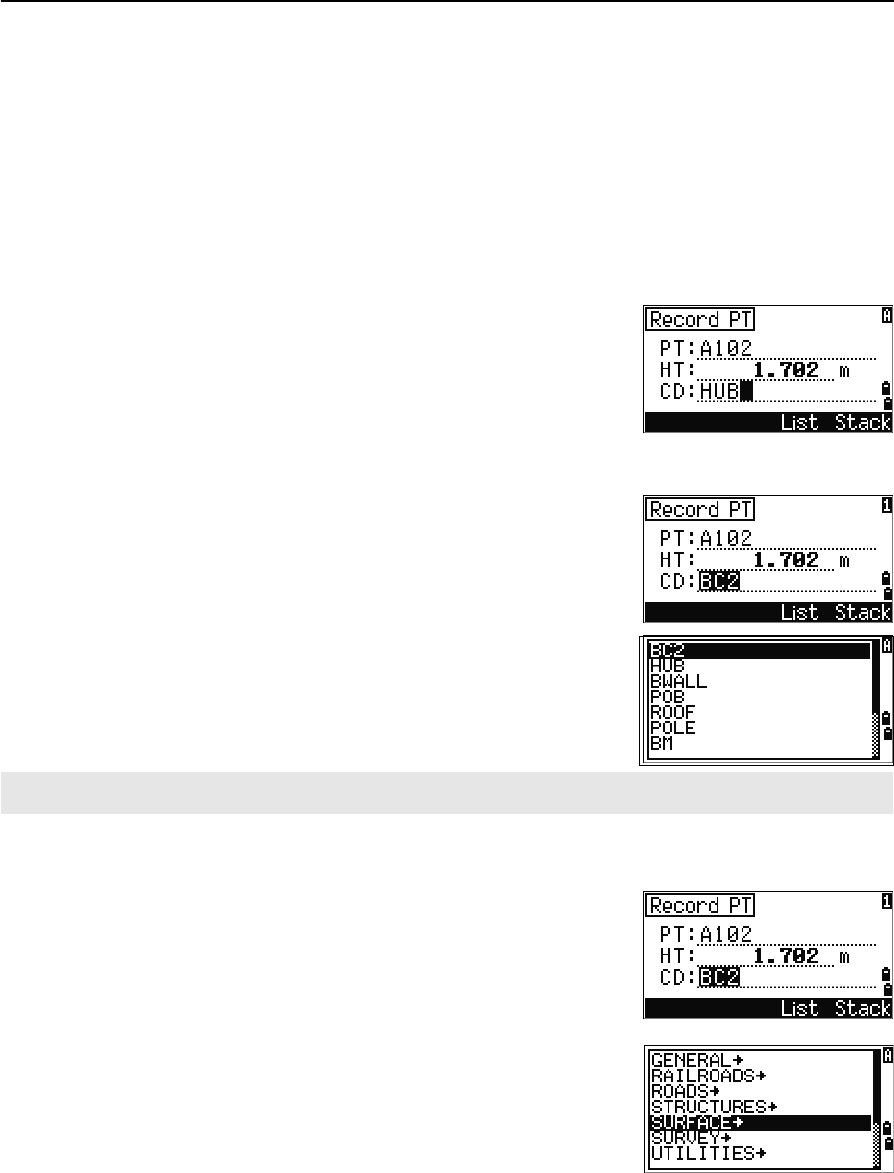
[COD] key
In the BMS, press [COD] to change the default feature code that will appear in the CD
field when you record a point.
Setting the default code
When you press [COD] in the BMS, a window for
entering the feature code appears.
You can use the List and Stack softkeys to enter the
code.
To assign a new feature code to a numeric key, press [^] or [v] to highlight the code that you want to change. Then
press the Edit softkey.
You can use the DSP softkey to change the values shown in the measurement box, in the same way as you use
the [DSP] key in the Basic Measurement Screen (BMS).
3 Getting Started
34 Total Station Nivo Series Instruction Manual
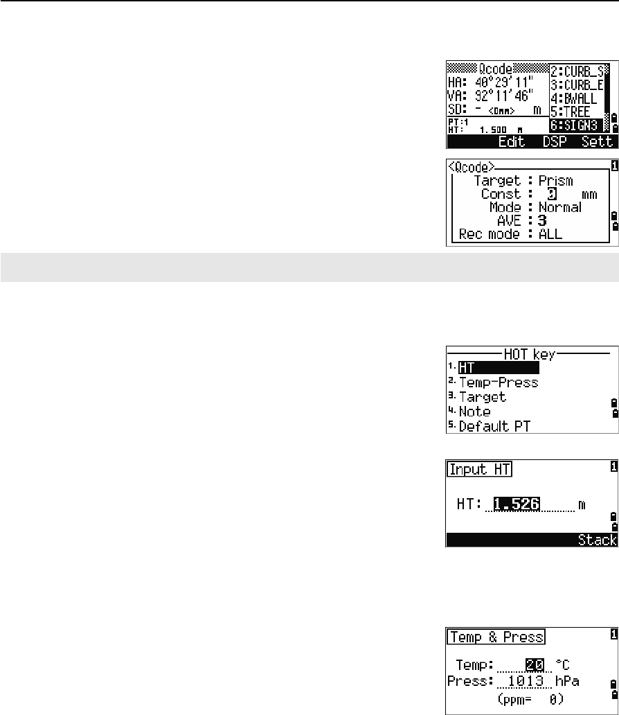
Qcode observations
To enter the Quick code observation routine, press the
Qcode softkey.
In this function, you can use the ten numeric keys to
both select a feature code and shoot a point.
To change the measurement mode for the Quick code
observation, press the Sett softkey.
[HOT] key
The HOT key menu is available on any observation
screen. To display the HOT key menu, press [HOT].
Changing the height of the target
To change the height of the target, press [HOT] to display
the HOT menu. Then either press [1] or select HT and
press [ENT].
Enter the height of the target, or press the Stack
softkey to display the HT stack. The HT stack stores
the last 20 HT values entered.
Setting the temperature and pressure
To set the current temperature and pressure, press [HOT]
to display the HOT menu. Then either press [2] or select
Temp-Press and press [ENT]. Enter the ambient
temperature and pressure. The ppm value is updated
automatically.
In Quick code measurement, the Rec mode can only be set to Confirm or ALL.
Total Station Nivo Series Instruction Manual 35
Getting Started 3
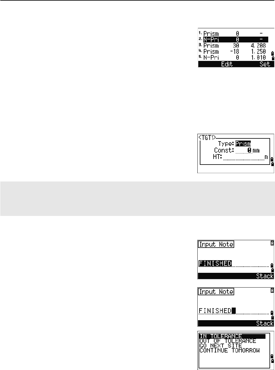
Selecting the target set
A target set specifies settings for the target type, the
prism constant, and height of target. When you change
the selected target set, all three settings are changed.
You can use this function to quickly switch between
two types of target, such as a reflector sheet and a
prism. You can prepare up to five target sets.
Press [HOT] to display the HOT menu. Then either press [3], or select Target and press
[ENT]. A list of the five target sets appears. To select a target set, either press the
corresponding numeric key ([1] through [5]), or use [^] or [v] to highlight the target set in
the list and press [ENT].
To change the settings defined in a target set, highlight the target set in the list. Then
press the Edit softkey.
Entering a field note
To enter a field note, press [HOT] to display the HOT
menu. Then either press [4], or select Note and press
[ENT].
This function can be used at any time on any
observation screen.
Each note can be up to 50 characters.
The note is stored as a CO record in the raw data.
To display a list of previously used notes, press the
Stack softkey. The stack stores the last 20 notes.
Use [^] or [v] to highlight a note in the list. Then press
[ENT] to select the note.
Type Prism/N-Prism
Const –999 to 999 mm
HT –9.990 to 99.990 m
HT can be left blank in the target set. If you leave it blank, the current HT value is always applied to the
measurement.
When a target set is selected, the Type and Const values are copied to both [MSR1] and [MSR2] settings, and to
the measurements in Qcode. If you have specified a value for HT, this value is also copied to the current HT.
3 Getting Started
36 Total Station Nivo Series Instruction Manual
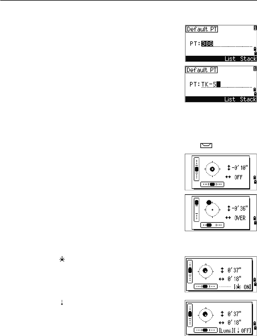
Setting the default point name
To change the default point name, press [HOT] to display
the HOT menu. Then press [5], or select Default PT
and press [ENT].
This function is available from any observation screen.
Modify the default point name for the next record.
Press [ENT] to confirm the new default point name. The
new point name is appears as the default PT name on
the input screen.
Bubble indicator
The bubble indicator is automatically displayed if the instrument goes out of level
while the compensators are turned on, and also appears after the start up screen.
To display the bubble indicator in an observation screen, press .
The Nivo series has two-axis level compensation. To
turn the leveling compensators on or off, press [<] or [>].
When the leveling compensators are turned off, the text
OFF appears on the screen.
If the instrument is more than ±3'30" out of level, the
text OVER appears on the screen.
To return to the observation screen, press [ESC] or [ENT].
Laser plummet
Laser plummet ON/OFF
Press [ ON] to enable the laser plummet.
Press [ESC] to close the bubble indicator window.
Press [ OFF] to disable the laser plummet.
Press [Lumi.] to open the luminance adjustment
window.
Press [ESC] to disable the laser plummet and close the
bubble indicator window. (Laser plummet is on.)
Total Station Nivo Series Instruction Manual 37
Getting Started 3
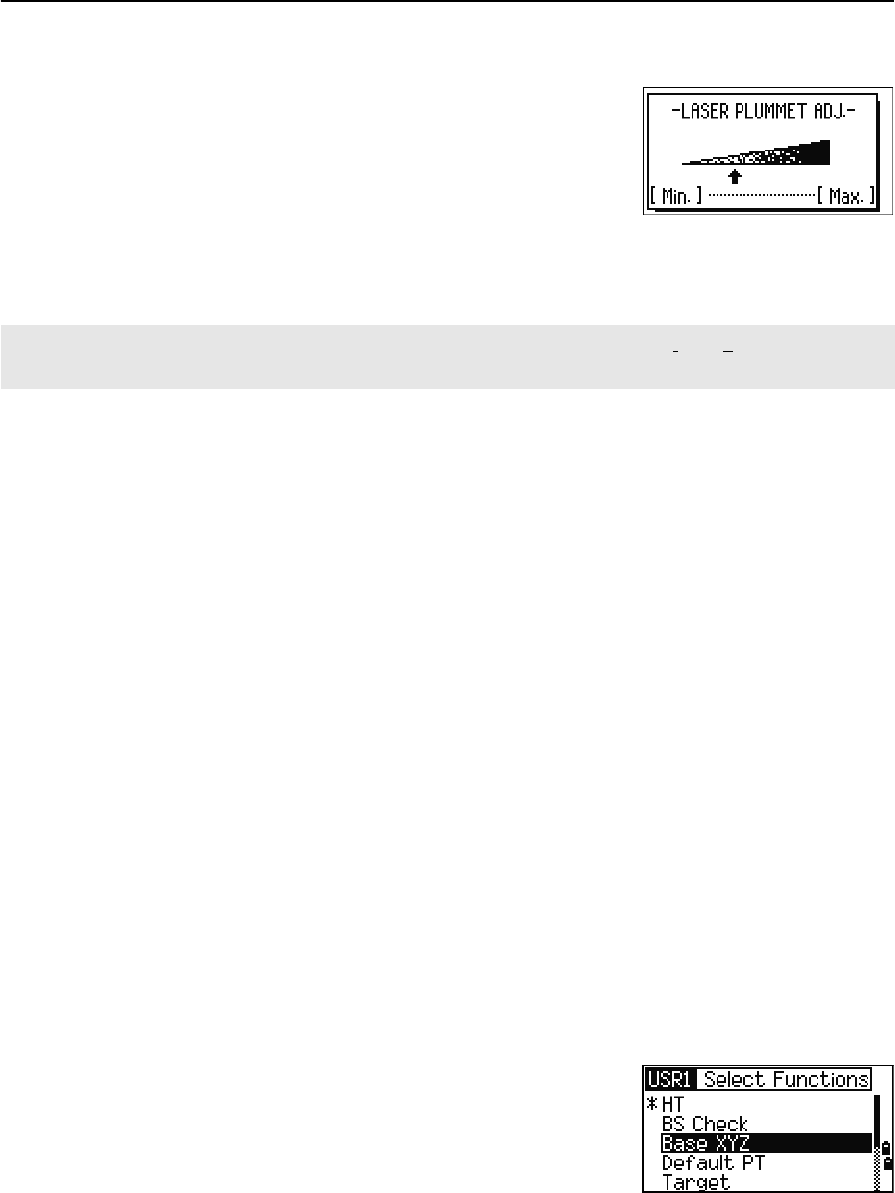
Laser luminance adjustment
Laser luminance can be set to 4 levels.
Press [Max.] to increase the luminance of the laser
plummet.
Press [Min.] to decrease the luminance of the laser
plummet.
Press[ESC] /[ENT] to return to the bubble indicator window.
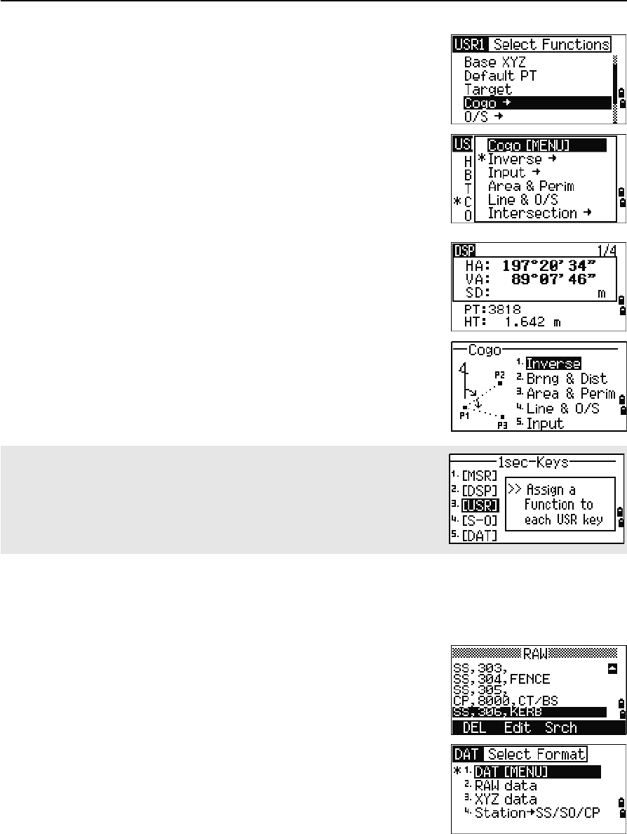
[USR] keys
If you use a function frequently in the field, you can assign it to the [USR1] or [USR2] key.
Whenever you press a [USR] key, the function that is assigned to that key is activated
directly.
The following functions can be assigned to the [USR] keys:
•Input HT
•BS Check
•Base XYZ
•Default PT
•Select Target
•Input Temp-Press
•Input Note
•The following menus, or a single function from one of these menus:
–Cogo
–O/S
–PRG
By default, Input HT is assigned to [USR1], and no function is assigned to [USR2].
Hold down the [USR] key for one second to display the
list of functions that can be assigned to the key. The
currently assigned function is indicated by an asterisk
(*) beside the function name.
To change the function that assigned to the key, press [^]
or [v] to highlight the function. Then press [ENT].
The current setting of leveling compensators is indicated by header characters (:, #, :, and #) after field labels
(such as HA, VA, SD, and HD) in observation screens. For more information, see Header characters, page 32.
3 Getting Started
38 Total Station Nivo Series Instruction Manual
If an item on the list has an arrow (->) beside it, this
item is a menu. If you highlight a menu item and then
press [ENT], a sub-menu appears.
The first item on the sub-menu ends with the text
[MENU]. If you select this item, the whole menu is
assigned to the [USR] key.
To assign a specific function from the sub-menu, press
[^] or [v] to highlight the function. Then press [ENT].
Once you have assigned a function to a [USR] key, it is
called directly whenever you press that [USR] key in the
BMS.
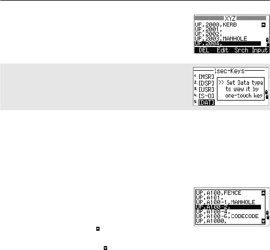
[DAT] key
Use the [DAT] key to quickly access data in the current job from observation screens.
When you press [DAT] in the BMS or in observation
screens in functions such as Stakeout, 2Pt RefLine, and
Arc RefLine, the assigned data in the current job
appears.
Hold down [DAT] for one second in the BMS or an
observation screen to display the Select Format screen.
Use this screen to change the type of data that is
assigned to [DAT]. Press [1] or select DAT [MENU] to
display the Data menu whenever you press [DAT].
To change the type of data that is assigned to the [USR] keys in MENU >
1sec-Keys > [USR]. For more information, see [USR] key settings,
page 132.
Total Station Nivo Series Instruction Manual 39
Getting Started 3
When you select an option from this screen, the change
is applied immediately, and the selected data type
appears.
Press [ESC] to return to the previous observation screen.
List Display
Available jobs or data appear in a list display when you do any of the following:
•view or edit data (MENU > Data)
•open the code list, point list, or Job Manager (MENU > Job)
•search for points or codes
In the list, the current cursor position is shown in
reverse video (it appears as white text on a black
background).
Press [^] or [v] move the cursor one line up or down.
If the Page Up icon appears, there are more pages
before the current page. Press [<] to move up one page.
If the Page Down icon appears, there are more pages after the current page. Press [>]
to move down one page.
To select an item from the list, move the cursor onto the item and press [ENT].
Inputting Data
Entering a point name or number
You can use numeric or alphanumeric names up to 16 characters long to identify
points.
The default name for a new point is the last point name entered, with the last digit
incremented. For example, if the last point name was A100, the default name for the
next point is A101.
To change the type of data that is assigned to [DAT], go to MENU >
1sec-Keys > [DAT]. For more information, see [DAT] key settings,
page 133.
3 Getting Started
40 Total Station Nivo Series Instruction Manual
If the last character of the previous point name is alphabetic, the default point name is
the last point name.
When the cursor is in a PT (point) field, there are several ways to specify a point, or
input coordinates.
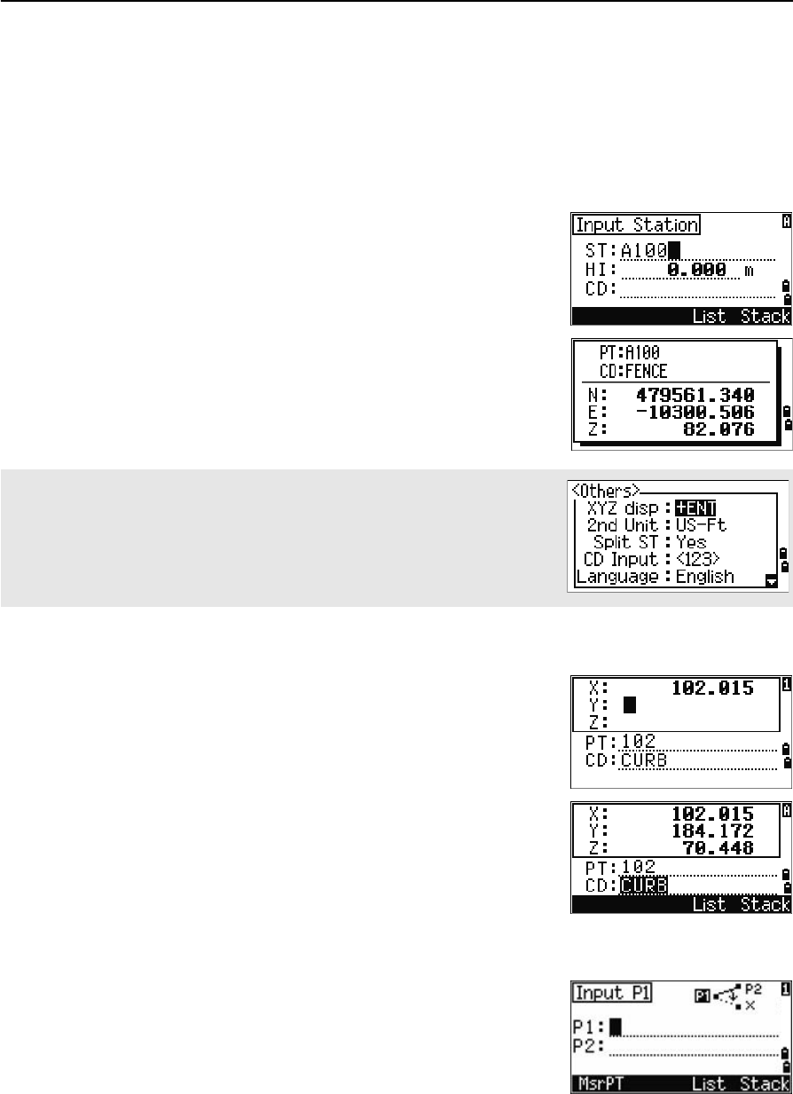
Entering an existing point
When you enter a known point name or number, the
coordinates of that point are displayed briefly. A short
beep sounds before the next screen appears or the next
field is selected.
Entering a new point
When you input a new point name or number, a
coordinate input screen appears. Enter the point’s
coordinates in NE, NEZ, or elevation-only (Z) format.
Press [ENT] on the last line (the CD field) to store the
point in the current job.
Pressing [ENT] without a point name
To use a point without recording the coordinates, press
[ENT] in a PT field, without entering a point name.
To adjust the duration of the coordinate window display, go to MENU >
Settings > Others. To leave the window open until you press [ENT],
set the XYZ disp field to +ENT. For more information, see page 112.

Total Station Nivo Series Instruction Manual 41
Getting Started 3
The input coordinates are used in the calculation. They
are not saved in the database.
Specifying a wildcard (*)
If you include an asterisk (*) when you enter a point or
code name, a list of points that match the entered text
appears.
Use [^] or [v] to move the cursor to the point that you
want to use. Then press [ENT].
If the Page Up or Page Down icons are displayed,
use [<] or [>] to page up or page down the list.
When you select a point from the list, its coordinates
are displayed and a beep sounds.
Recording an instant measurement
You can also input a point by recording an instant
measurement. To do this, press the MSR softkey.
An observation screen appears.
Press [MSR1] or [MSR2] to start a measurement. To change
the height of the target, press the HT softkey.
To go to the point recording screen when you have
finished the measurement, press [ENT].
Enter the point or code name. Press [ENT].
3 Getting Started
42 Total Station Nivo Series Instruction Manual
Entering a point from the stack
The point stack is a list of recently used points. To
display the stack, press the Stack softkey when the
cursor is in the PT field.
Use [^] or [v] to move the cursor to the point that you
want to use. Then press [ENT].
When you return to the point input screen, the selected
point name is entered in the PT field, incremented by
one. For example, if you selected the A101 point,
A102 appears in the PT field.
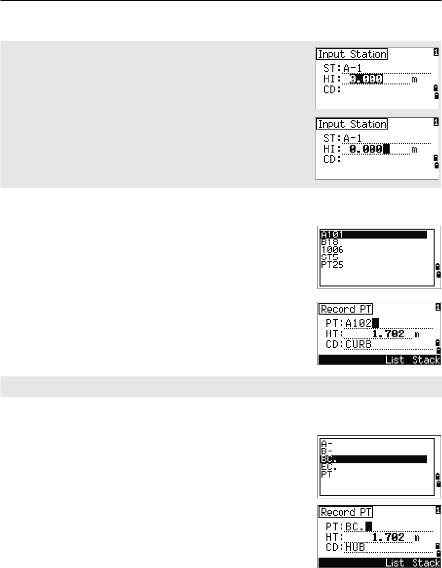
Entering a point from the point list
To display a list of existing points, press the List
softkey when the cursor is in the PT field.
Use [^] or [v] to move the cursor to the point that you
want to use. Then press [ENT].
When you return to the point input screen, the selected
point name is entered in the PT field. You can add
digits or alphabetic characters if required.
When you move the cursor to a field, the current or default value appears in
inverted text (this is the default “Replace All” input mode).
Press [>] to change the input mode to Overwrite mode and highlight the first
character. Press [<] to move the cursor the end of the string.
The stack shows the last 20 point names used, in chronological order from last used to first used.
Total Station Nivo Series Instruction Manual 43
Getting Started 3
Entering a code
The CD (Code) field always defaults to the last code used. You can change the
selected code on the input point screen, or you can press [COD] in the BMS. For more
information, see [COD] key, page 33.
You can use numeric or alphanumeric names up to 16 characters long to identify
codes.
Entering a code directly
To enter a code directly, press [MODE] to change the
input mode to alphanumeric or numeric mode. Then
use the keypad to enter the code.
Entering a code from the stack
The code stack is a list of recently used codes. The
stack may contain up to 20 codes.
To display the stack, press the Stack softkey when
the cursor is in the CD field.
Use [^] or [v] to move the cursor to the code that you
want to use. Then press [ENT].
The selected code is copied to the CD field.
Entering a code from the code list
To display a list of existing codes, press the List
softkey when the cursor is in the CD field.
To edit the code list, go to MENU > Data > Code
List. For more information, see Editing an item in the
point list or code list, page 126.
Use [^] or [v] to highlight the feature code that you want
to use. Then press [ENT].
When the instrument is rebooted, the code stack is cleared.
3 Getting Started
44 Total Station Nivo Series Instruction Manual
A layer has an arrow at the end of the code label. If you
highlight a layer in the list and then press [ENT], the
codes and layers in that layer are displayed.
When you return to the input screen, the selected code
is entered in the CD field.
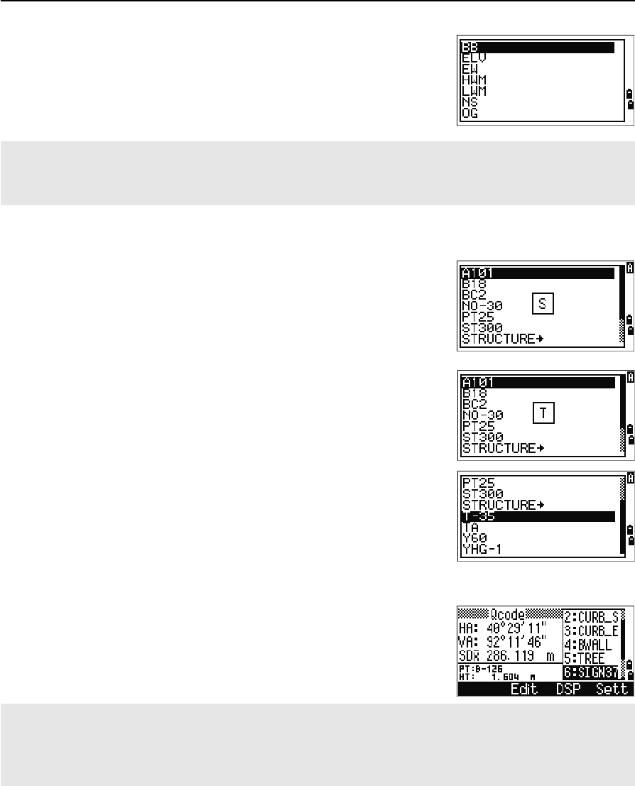
Advanced feature: Searching for a code by using the first character
To find a code quickly when the code list appears, use
the first-character search.
For example, to see feature codes that begin with T, use
the keypad to enter the letter T. To do this, press [1]
twice.
After each press of the key, the input mode field
displays the selected letter. For example, if you press
[1],S appears. If you quickly press [1] again, T appears.
If you do not press the [1] key again, the letter T is
selected.
Once you have selected a letter, the cursor moves to the
feature code beginning with that letter.
If there is no code beginning with that letter, the cursor
moves to the next available letter.
Qcodes
Quick codes (Qcodes) let you shoot and record many
points with feature codes in the field. You can register
up to ten Quick codes. To register Qcodes, press the
Edit softkey. For more information, see Quick code
measurement mode, page 33.
Items are shown in alphabetic order.
You can also use the first character search to quickly find a code. For more information, see Advanced feature:
Searching for a code by using the first character, page 44.
Press [MODE] to switch Qcodes on or off.
Press the Edit softkey to change the Qcode. You can edit the entire code, or just the number at the end of the
code.
You can still use [DSP] to change the background displays.
Total Station Nivo Series Instruction Manual 45
Getting Started 3
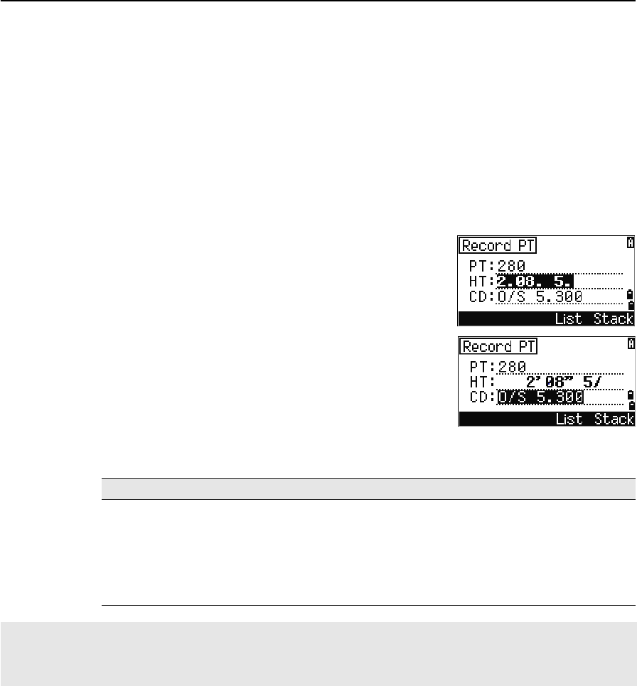
Entering values in feet and inches
When either US Survey Feet (US-Ft) or International Feet (I-Ft) is selected as the
distance unit, you can enter and display distances, HIs, HTs, and coordinate values
either in decimal feet, or in feet and inches For more information, see Unit, page 111,
and Others settings, page 112.
To enter values in feet and inches in an input screen, enter the elements, separated by
periods (.), in the following format:
The default denominator is 16. If the denominator is
16, you do not have to enter it, and it is not displayed
on the screen.
For example, if you enter
[2] [.] [0] [8] [.] [5] [.] [ENT], it appears as 2'08" 5/ (2 feet, 8
and 5/16ths inches).
The following examples show how various values are
entered:
Jobs
To record data on the instrument, you must create or open a job.
BTip – Before you use the instrument for the first time, check the job settings.
<Feet> [.] <Inches> [.] <Numerator> [.] <Denominator> [ENT]
(0–11) (0–15) (0–99)
To enter ... Type ...
65' 5 3/8" [6] [5] [.] [5] [.] [3] [.] [8] [ENT]
65' [6] [5] [ENT]
65' 5" [6] [5] [.] [5] [ENT]
65' 5 3/8" [6] [5] [.] [5] [.] [6] [ENT]
5 3/8" [0] [.] [5] [.] [3] [.] [8] [ENT] or [0] [.] [5] [.] [6] [ENT]
The numerator and denominator that you enter are automatically converted to the closest value from the
following list: 0, 1/8, 1/4, 3/8, 1/2, 5/8, 3/4, 7/8, 1/16, 3/16, 5/16, 7/16, 9/16, 11/16, 13/16, 15/16.
If the denominator is 16, it is not shown on the screen.
3 Getting Started
46 Total Station Nivo Series Instruction Manual
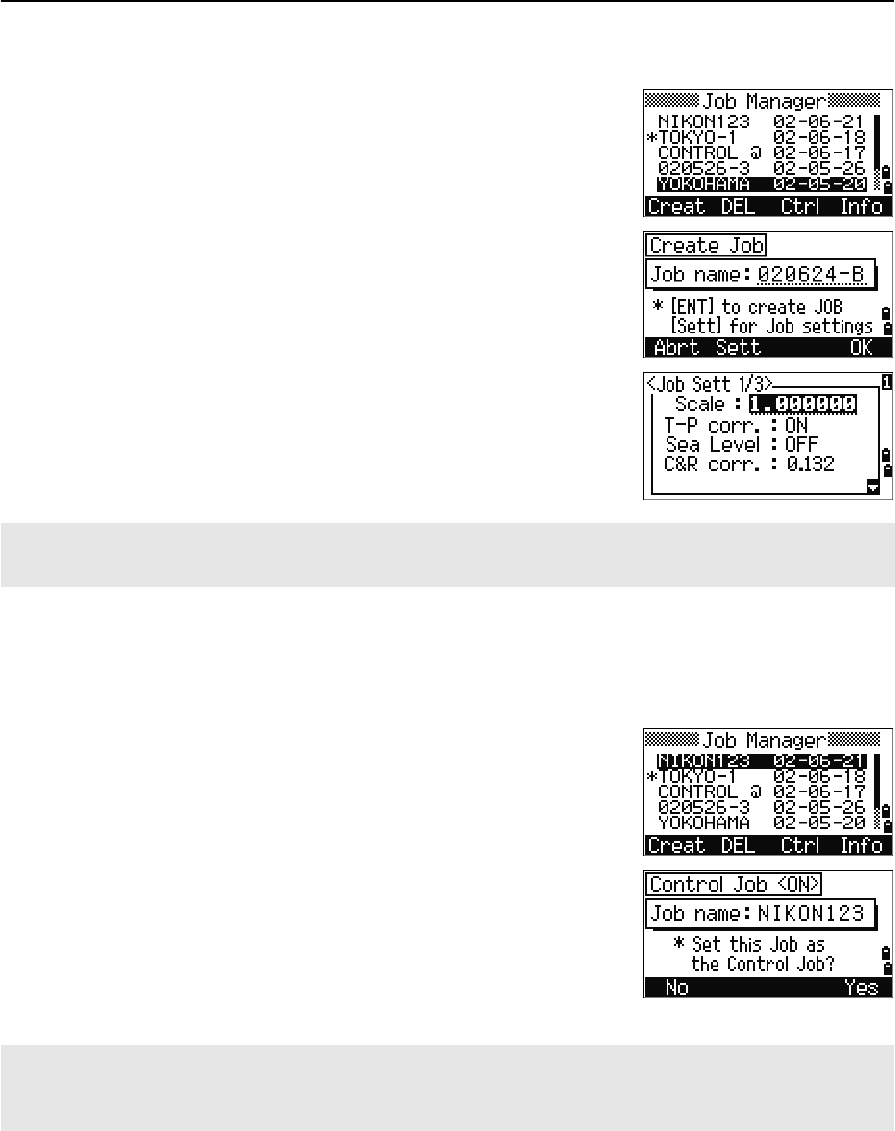
Creating a new job
1. Press [MENU] to open the MENU screen.
2. Press [1] to open the Job Manager.
3. Press the Creat softkey to open the Create Job
screen.
4. Enter the job name.
5. Press the Sett softkey to check the job settings.
You cannot change a job’s settings once you
have created the job.
6. Press [ENT] in the last field of the Job Sett screen
to create the new job.
Creating a control job
A control job, or common file, stores coordinate data that is used by several field jobs.
You can create a control job in the office.
1. Press [MENU] to open the MENU screen.
2. Press [1] or select Job to open the Job Manager.
3. Move the cursor to the job that you want to use
as the control job.
4. Press the Ctrl softkey.
5. Press the Yes softkey.
For more information, see Creating a control job,
page 46.
If either of the messages MAX 32JOBs or Data Full appears, delete at least one existing job to free space. You
cannot free space by deleting records in an existing job.
When you enter a point name or number, the system searches in the current job first. If the point is not found in
the current job, the search is automatically extended to the control job. If the point is found in the control job, the
selected point is copied to the current job as a UP record.
Total Station Nivo Series Instruction Manual 47
Getting Started 3
Measuring Distances
Sighting a prism reflector
CWARNING – Never look at the sun through the telescope. If you do, you may damage or lose
your eyesight.
CWARNING – Precautions should be taken to ensure that persons do not look directly, with or
without an optical instrument, into the beam.
CWARNING – Laser beam path should be located well above or below eye level wherever
practicable.
Sight the telescope to see crosshairs at the center of the prism
reflector.
Measuring distances
To take a distance measurement, press [MSR1] or [MSR2] in
the Basic Measurement Screen (BMS) or in any
observation screen.
While the instrument is taking a measurement, the
prism constant appears in a small font.
For information on how to assemble the prism reflector, see Setting Up the Prism Reflector, page 20.
Sighting a single prism
Sighting a tiltable single prism
3 Getting Started
48 Total Station Nivo Series Instruction Manual
If the average count is set to 0, measurements are taken
continuously until you press [MSR1],[MSR2], or [ESC]. Each
time a measurement is taken, the distance is updated.
If the average count is set to a value from 1 to 99, the
averaged distance appears after the last shot. The field
name SD changes to SDx to indicate the averaged data.
Measurement settings
To view the measurement settings,hold down [MSR1] or
[MSR2] for one second.
Use [^] or [v] to move the cursor between the fields. Use
[<] or [>] to change the value in the selected field.
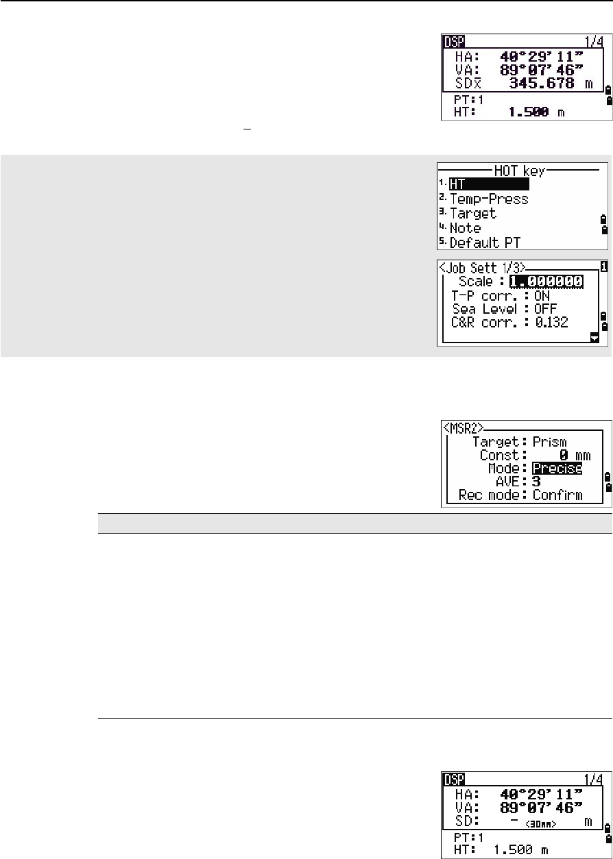
Target field
If the measurement is started with the Target field set
to Prism, there is a dash “–” in front of the prism
constant.
If the measurement is started with the Target field set
to N-prism, there is a square bracket “]” in front of the
prism constant.
To change the height of target (HT), temperature, or pressure, press [HOT]. For
more information, see [HOT] key, page 34.
Settings that relate to corrections
(T-P corr, Sea Level, C&R corr., and Map projection) are included in the job
settings. These settings are job-specific. If you need to change any of these
settings, you must create a new job. For more information, see Job settings,
page 93, and Settings, page 108.
Field Values
Ta r g et • P r i sm
• N-prism
Const (prism constant) –999 mm through 999 mm
Mode • Precise
•Normal
AVE (Average count) 0 (Continuous) through 99
Rec mode One of the following:
•MSR only
•Confirm
•ALL
Total Station Nivo Series Instruction Manual 49
Getting Started 3
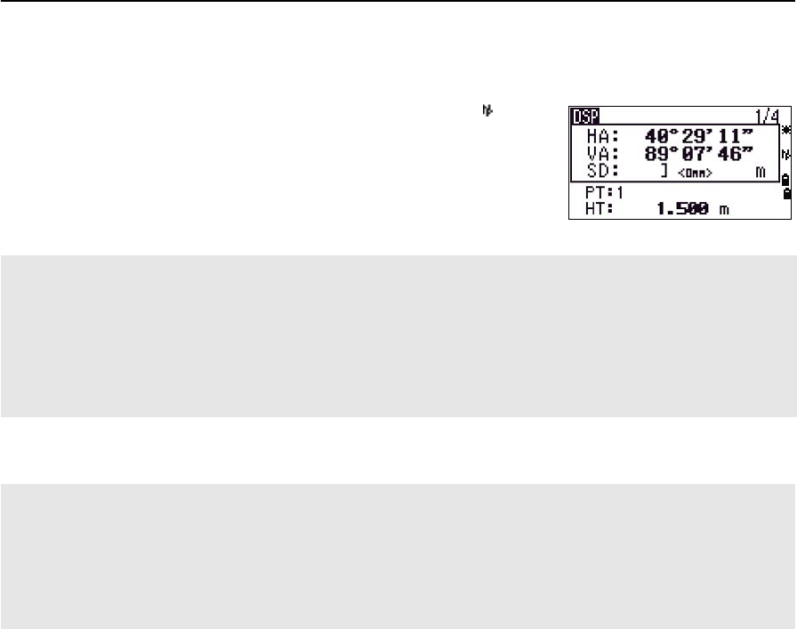
The symbol then constantly runs from left to right over the prism constant in the
display.
When an N-prism measurement is taken, the icon
appears in the status bar (above the battery icon).
Rec mode field
Incorrect Target settings may result in measurements outside the precision and intervals specified for the
instrument.
If a prism target is aimed in the N-prism mode, the warning message "Signal High! → Try Prism Mode" will be
displayed because of the excessive light reflection.
A measurement made immediately after changing the target setting may take a longer time than usual.The
Target setting is used to apply better cyclic-error adjustment in distance measurement. It efficiently eliminates
multipath reflection.
The Rec mode setting controls how the [MSR1] and [MSR2] keys operate in the BMS.
The MSR only setting is the default measurement mode. After a measurement, the instrument stops in the BMS
and waits for you to press [ENT] before recording the point.
The Confirm setting displays the Record PT screen before data is recorded.
The ALL setting is a quick shooting and recording mode. The instrument automatically records the point using
the default PT/CD. The instrument then returns to the BMS for the next measurement.

3 Getting Started
50 Total Station Nivo Series Instruction Manual

CHAPTER
4
Total Station Nivo Series Instruction Manual 51
Applications 4
In this chapter:
QHA Reset and Angle Operations
QStation Setup
QStakeout
QProgram Key
QRecording Measurement Data
QMeasuring Offsets
4 Applications
52 Total Station Nivo Series Instruction Manual
HA Reset and Angle Operations
To open the Angle menu, press [ANG] in the BMS. To
select a command from this menu, either press the
corresponding number key, or press [<] or [>] to highlight
the command and then press [ENT].
Setting the horizontal angle to 0
To reset the horizontal angle to 0, press [1] or select 0-Set in the Angle menu. The
display returns to the Basic Measurement Screen (BMS).
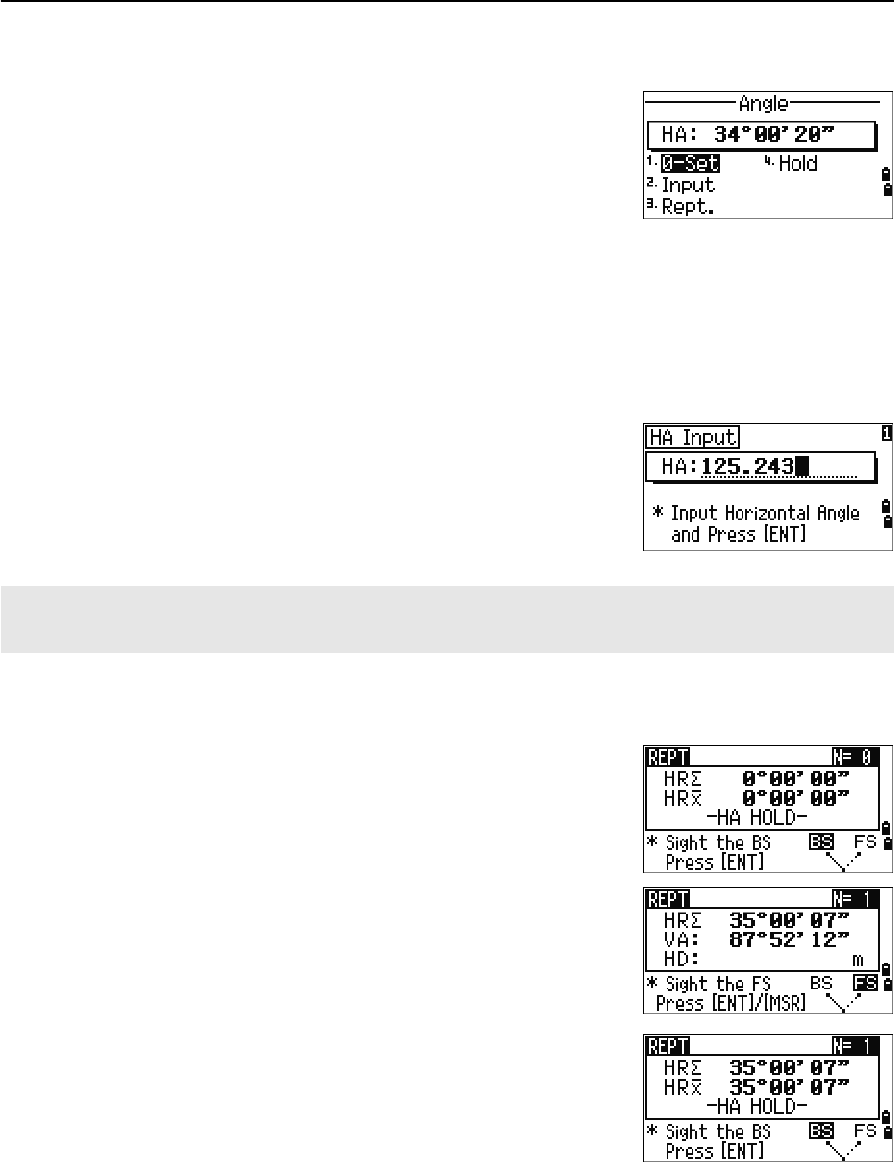
Entering the horizontal angle
To display the HA Input screen, press [2] or select
Input in the Angle menu. Use the numeric keys to
enter the horizontal angle. Then press [ENT].
Recording a foresight point after repeat angle measurement
1. To activate repeat angle measurement, press [3]
or select Rept. in the Angle menu.
HR=0 appears.
2. Sight the backsight and press [ENT].
3. Sight the foresight and press [ENT].
The horizontal angle is accumulated and the
value is held again.
4. To end repeat angle measurement, press [ESC].
5. When you have accumulated enough horizontal
angle between the backsight and the foresight,
press [MSR1] or [MSR2] to take a measurement to
the foresight.
To enter 123°45'50", type [1] [2] [3] [.] [4] [5] [5] [0].
The displayed value is rounded to the minimum angle increment.
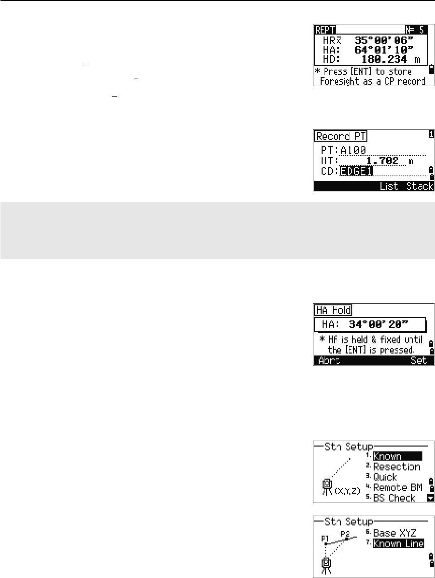
Total Station Nivo Series Instruction Manual 53
Applications 4
The averaged horizontal angle appears. This
value is fixed until the process is finished or
cancelled.
HRx is not updated even if the instrument is
moved.
6. Press [ENT] to store the foresight as a CP record.
Check the PT, HT, and CD values. Then press
[ENT] to record.
Horizontal angle hold
To hold the horizontal angle to the current value, press
[5] or select Hold in the Angle menu.
To set the horizontal angle to the displayed value, press
[ENT] or the Set softkey.
To cancel the process and return to the Basic
Measurement Screen (BMS), press [ESC] or the Abrt softkey.
Station Setup
To open the Stn Setup menu, press [STN] in the BMS.
To select a command from this menu, press the
corresponding number key. Alternatively, press [<] or [>]
to highlight the command and then press [ENT]. Press [^]
or [v] to move up or down one page.
The last function used is highlighted.
HRx = HR¦÷ N
HA = BSAz + HRx (normalized)
In repeat angle measurement, the HA is replaced by HR¦. The number of repeat angles appears at the top of
the screen (for example, N= 5).
Horizontal angles can be measured up to 1999°59'59".
This function stores both raw and XYZ data as CP records, regardless of the Store DB setting.
4 Applications
54 Total Station Nivo Series Instruction Manual
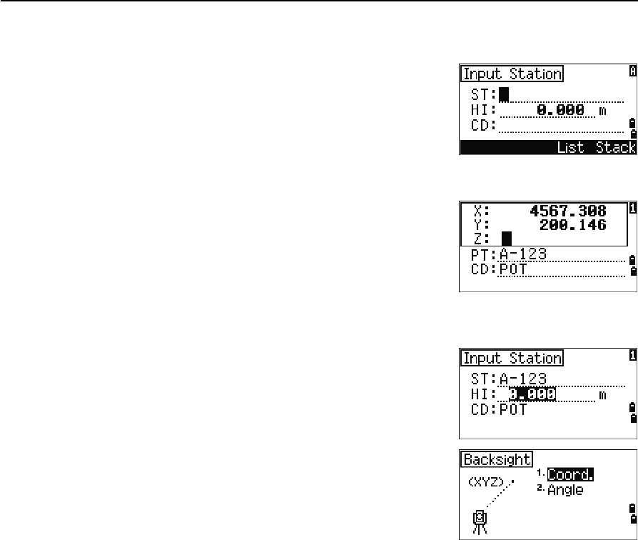
Setting up a station with known coordinates or azimuth
1. Press [1] or select Known in the Stn Setup menu.
2. Enter a point name or number in the ST field.
–If the input point number or name is an
existing point, its coordinates are displayed
and the cursor moves to the HI (Height of
instrument) field.
–If the point is new, a coordinate input
screen appears. Enter the coordinates for
the point. Press [ENT] after each field. When
you press [ENT] in the CD field, the new
point is stored.
–If the specified point has a code, the code
appears in the CD field.
3. Enter the instrument height in the HI field and
then press [ENT].
The Backsight screen appears.
4. Select an input method for defining the
backsight point.
–To sight the backsight by entering
coordinates, see below.
–To sight the backsight by entering the azimuth and angle, see page 56.
Total Station Nivo Series Instruction Manual 55
Applications 4
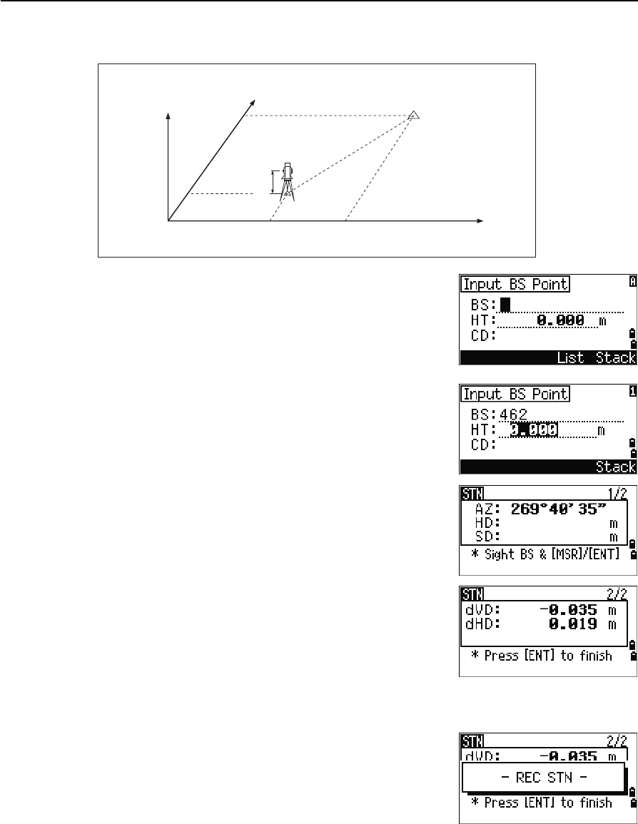
Sighting the backsight by entering coordinates
1. To enter coordinates for the backsight point
(BS), press [1] or select Coord in the Backsight
screen.
2. Enter the point name. If the point exists in the
job, its coordinates are shown.
3. If you intend to take a distance measurement to
the BS, enter the height of target in the HT field.
4. Sight the BS. Press [ENT] to complete the setup.
–To record a full shot (with HA, VA, and SD
values) to the BS, press [MSR1] or [MSR2].
–If you are measuring to a known coordinate
BS, press [DSP] to display a QA screen. The
QA screen shows the dHD and dVD values,
which indicate the difference between the
measured distance and the distance
calculated from the known coordinates.
5. To record the station, press [ENT].
6. To finish the station setup after taking a distance
measurement, press [ENT]. ST and F1 records are
stored to the current job.
AZ Azimuth calculated by coordinates
Z
Y
X0
X
Xb
Y0 Yb
Backsight point
(Xb, Yb, Zb)
Station point
(Xi, Yi, Zi)
Instrument height
4 Applications
56 Total Station Nivo Series Instruction Manual
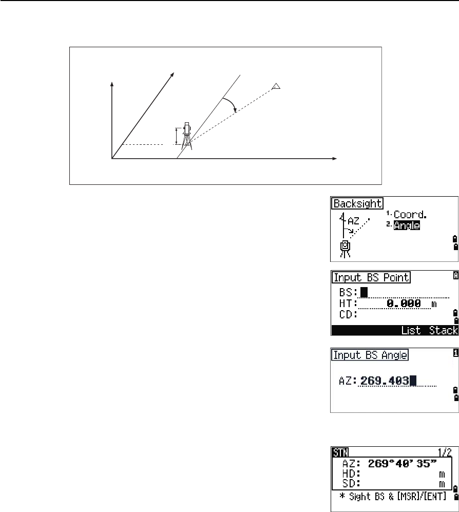
Sighting the backsight by entering the azimuth angle
1. To enter the azimuth angle to the backsight
point, press [2] or select Angle in the Backsight
screen.
2. If there is no point name for the BS, press [ENT]
on the BS field.
3. In the AZ field, enter the azimuth angle to the
BS point.
If you press [ENT] without entering a value in the
AZ field, the azimuth is automatically set to
0°00'00".
4. Sight the BS point and press [ENT]. ST and F1
records are stored in the job.
Backsight point
Azimuth
Station point
(Xi, Yi, Zi)
Instrument height
X
Z
X0
Y0 Y
Total Station Nivo Series Instruction Manual 57
Applications 4
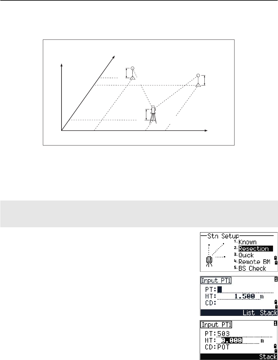
Setting up a station using multiple point resection
A resection sets up the station using angle/distance measurements to known points.
You can use a maximum of 10 points in a resection. Measurements can be distance
and angle, or angle only. Calculation starts automatically when enough measurements
are taken.
You can delete poor observations and recalculate if necessary. You can also select the
BS point.
1. To start the resection, press [2] or select
Resection in the Stn Setup menu.
2. Enter the point name for the first observation
point (PT1).
3. Enter the target height and press [ENT].
If the angle between known point 1 and known point 2 (measured from the station point) is extremely acute or
extremely oblique, the resulting solution will be less reliable geometrically. For geometric reliability, select known
point locations (or station point locations) that are widely spaced.
Z
X0
X2
X1
X
Height 1
Height 2
Instrument height
Station point (Xi, Yi, Zi)
Y1 Y0 Y2 Y
Known point 1
(X1, Y1, Z1)
Known point 2
(X2, Y2, Z2)
4 Applications
58 Total Station Nivo Series Instruction Manual
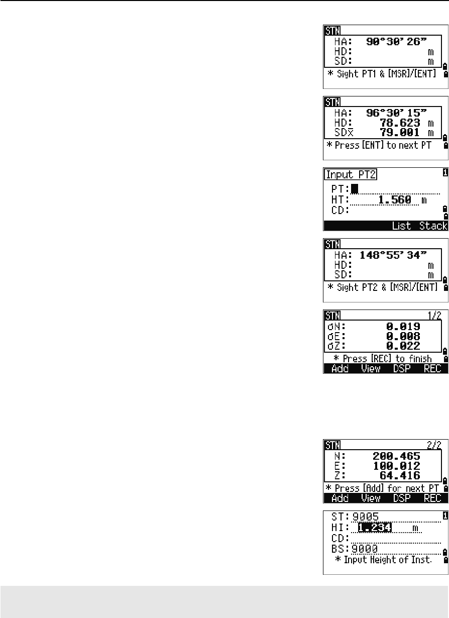
4. Sight PT1 and press [MSR1] or [MSR2].
5. To proceed to the next point, press [ENT].
6. Enter the second point (PT2) and its height of
target.
7. Measure to PT2 and press [ENT].
When the instrument has enough data, it
calculates the station (STN) coordinates.
–If more than the minimum required data is
available, a standard deviation screen
appears.
–To take measurements to strengthen
geometry of the resection, press the Add
softkey. For information about the View
softkey, see Advanced feature: Viewing and
deleting a measurement in resection,
page 59.
8. When the results are satisfactory, record the
station. To do this, press [ENT] or the REC softkey.
9. Enter the height of instrument, if required. Press
[ENT]. The ST field defaults to the last recorded
PT + 1.
10. To change the station name, move to the ST field
and edit or replace the text.
If you have set Split ST to Yes, the ST field defaults to the last recorded ST value + 1. For more information, see
Others settings, page 112.
Total Station Nivo Series Instruction Manual 59
Applications 4
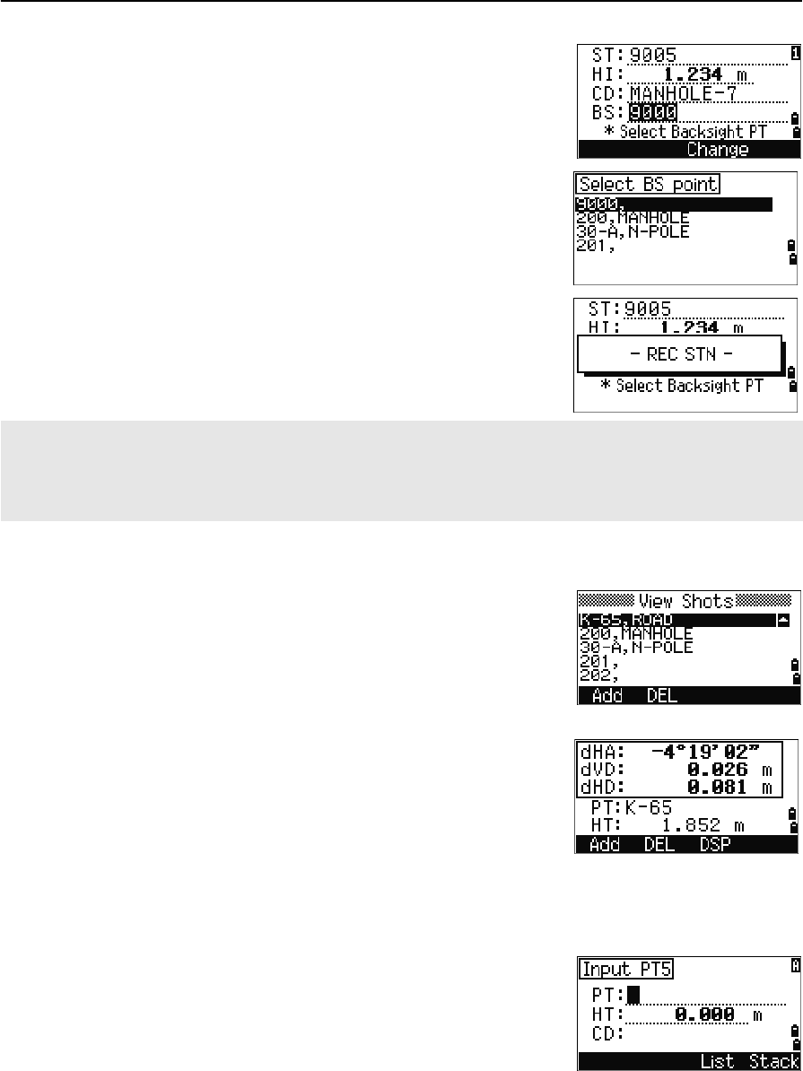
BS defaults to the first observed point.
11. To change the BS, press the Change softkey.
12. Select the BS point that you want to use and
press [ENT].
13. To finish the resection setup, move the cursor to
the BS field and press [ENT].
Advanced feature: Viewing and deleting a measurement in resection
To check the measurements to each known point, press
the View softkey on the calculated STN (sigma or
coordinate) screen.
To delete a measurement (because of large sigma values, for example), highlight the
measurement data or display the detail screen for the measurement. Then press the
DEL softkey. The STN coordinates are automatically recalculated.
To continue resection observations, press the Add
softkey. The input screen for the next PT appears.
The minimum data required for a resection is either three angle shots, or one angle shot and one distance shot.
If you use a distance shot, the distance between the target points must be greater than the measured distance.
Stn-Z is calculated from distance-measured data. If no distances are measured, then Stn-Z is calculated using
angle-only measurements to points with 3D coordinates.
dHA Distributed HA errors in each direction
dVD VD errors between measured distance and calculated
distance
dHD HD errors between measured distance and
calculated distance
4 Applications
60 Total Station Nivo Series Instruction Manual
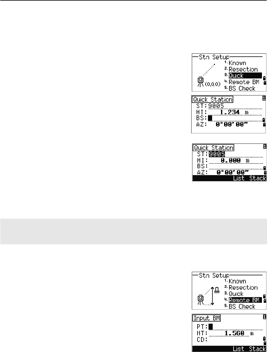
Setting up the station quickly without coordinates
The station point (ST) in this function defaults to a new point number. For the new
point, MP (0, 0, 0) is stored as the coordinates. When the ST is manually changed to a
known point name, the station is set up on the coordinates of the known point.
1. To enter Quick Station setup, press [3] or select
Quick in the Stn Setup menu.
2. No default PT is assigned to the BS. Leave this
field blank, or enter a BS point name.
3. The backsight azimuth (AZ) defaults to zero, but
you can change this.
4. To complete the station setup, sight the BS and
press [ENT].
When you press [ENT] in the AZ field, both HA and AZ are reset to the value you
have entered.
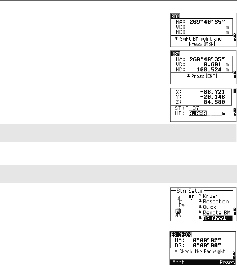
Determining station elevation
1. Press [4] or select Remote BM in the Stn Setup
menu.
2. Enter the BM point and press [ENT]. When the
point is found, it appears briefly. The cursor then
moves to the HT field.
3. Enter the HT and press [ENT].
ST Station point (defaults to the last recorded PT + 1, or
ST + 1, depending on the Split ST setting)
HI Height of instrument
BS Backsight point (blank)
AZ Backsight azimuth (defaults to zero)
Even if both ST and BS are known points, this function does not calculate the backsight angle (AZ)
automatically. To calculate the AZ between two known points (ST and BS), use Station Setup >
Known. For more information, see Setting up a station with known coordinates or azimuth, page 54.
Total Station Nivo Series Instruction Manual 61
Applications 4
4. Sight the BM point and press [MSR1] or [MSR2].
The updated station coordinates are displayed.
You can change the HI in this screen.
5. To record the updated STN, press [ENT].
Checking and resetting the backsight direction
1. To enter the backsight (BS) check function,
press [5] or select BS Check in the Stn Setup
menu.
2. Do one of the following:
–To reset the horizontal angle to the HA set in the last station setup sight the
BS and press the Reset softkey or press [ENT].
–To cancel the process and return to the BMS, press the Abrt softkey or
press [ESC].
When the HI is changed, the Z coordinate is updated before the station is recorded.
You must complete a station setup before you use the Remote Benchmark function.
You must complete a station setup before you use the BS check function.
This function always refers to the backsight point from the last ST record stored in the current open job.
HA Current HA reading
BS The HA to the BS in the last station setup. Enter
station coordinates for observations without recording
data.
4 Applications
62 Total Station Nivo Series Instruction Manual
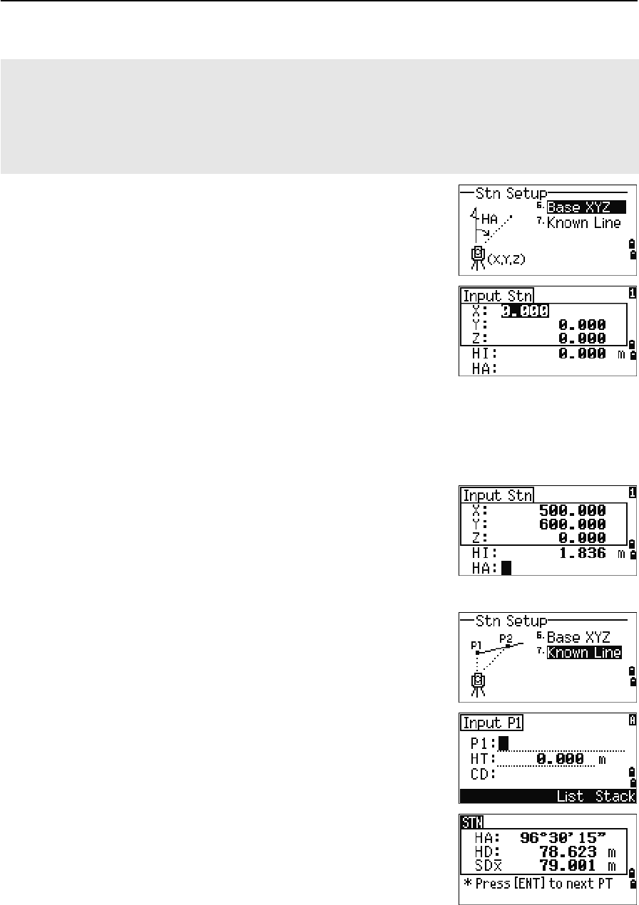
Base XYZ function:
1. To enter the Base XYZ function, press [6] or
select Base XYZ in the Stn Setup menu.
The current instrument XYZ values are shown
as the default.
2. Enter the new instrument XYZ values and press
[ENT].
3. Do one of the following:
–To reset the horizontal angle, enter a value in the HA field and press [ENT].
–If you do not need to reset the HA, leave the
HA field blank and press [ENT].
The display returns to the BMS.
Two-point resection along a known line
1. To enter the Known Line function, press [7] or
select Known Line in the Stn Setup menu.
2. Enter a known point as P1.
If you enter a new point name, a coordinate
input screen appears.
Sight P1 and press [MSR1] or [MSR2] to take a
measurement. Press [ENT].
Base XYZ does not store a ST record, so the BS Check cannot check the backsight when you enter a station
using Base XYZ.
To store raw data, use one of the other functions in the Stn Setup menu. This function does not store an ST
record in the job.
You can use this function without an open job. If there is an open job when you use this function, a CO record is
stored to indicate that the instrument’s base coordinates have changed.
Total Station Nivo Series Instruction Manual 63
Applications 4
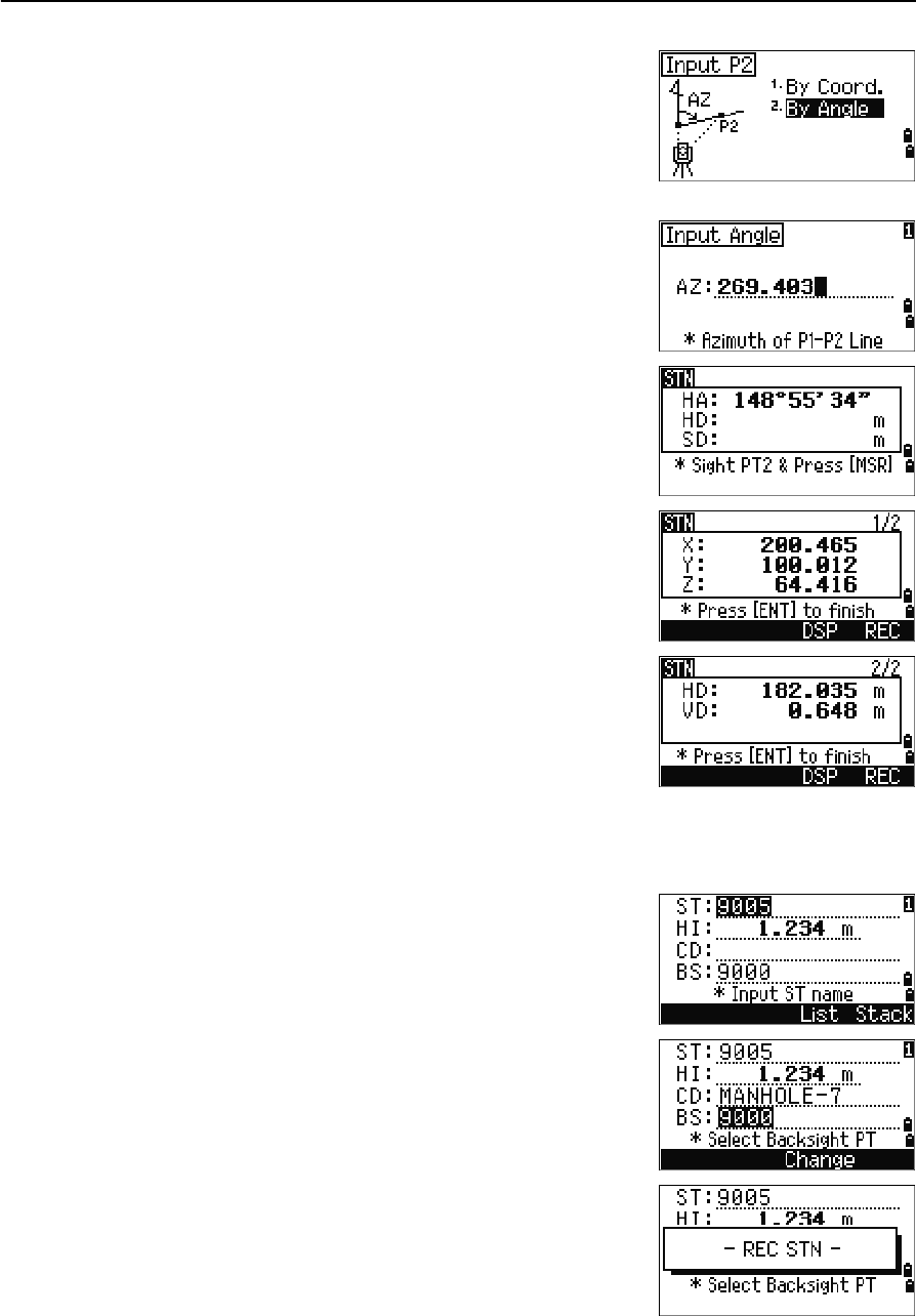
3. Choose how you want to define a known line:
–To define the line by entering P2
coordinates, press [1] or select By Coord.
–To define the line by entering the azimuth,
press [2] or select By Angle.
4. If you select By Angle, the azimuth input
screen appears. Enter the angle value and press
[ENT].
A measurement screen appears.
5. Sight P2 and press [MSR1] or [MSR2] to take a
measurement. Press [ENT].
After the measurement to P2 is completed, the
coordinates of the station are calculated.
6. To record the station, press [ENT] or the REC
softkey.
7. To check your measurement, press the DSP
softkey. If you defined the line by entering its
azimuth, HD and VD between P1 and P2 are
displayed.
If you defined the line by entering the P2
coordinates, the difference of HD (dHD) and
VD (dZ) between your measurement data and input coordinate data are
displayed.
8. Enter the station name, the height of instrument
(HI), and a feature code (CD) if required. The
station name defaults to the last recorded PT + 1,
or last recorded ST + 1, depending on the Split
ST setting.
9. Backsight (BS) defaults to the first point (P1).
To change it, highlight the BS field and then
press the Change softkey.
10. To finish the setup and record the station, press
[ENT] in the BS field.
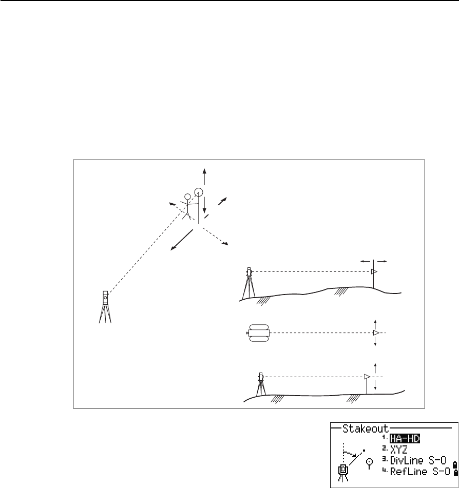
4 Applications
64 Total Station Nivo Series Instruction Manual
Sample records
CO, Temperature:20C Pressure:1013hPa Prism:0 …
ST,9005, ,265, ,1.2350,150.40300,150.40300
F1,265,1.6040,79.0010,90.30150,89.35260,
F1,200,1.4590,50.2300,269.4035,93.50110,
CO, P1-P2 HD=122.0350 VD=0.5600
Stakeout
To display the Stakeout menu, press [S-O].
R
IN L
OUT
CUT
FiLL
IN OUT
Height
of target
R
L
FILL
CUT
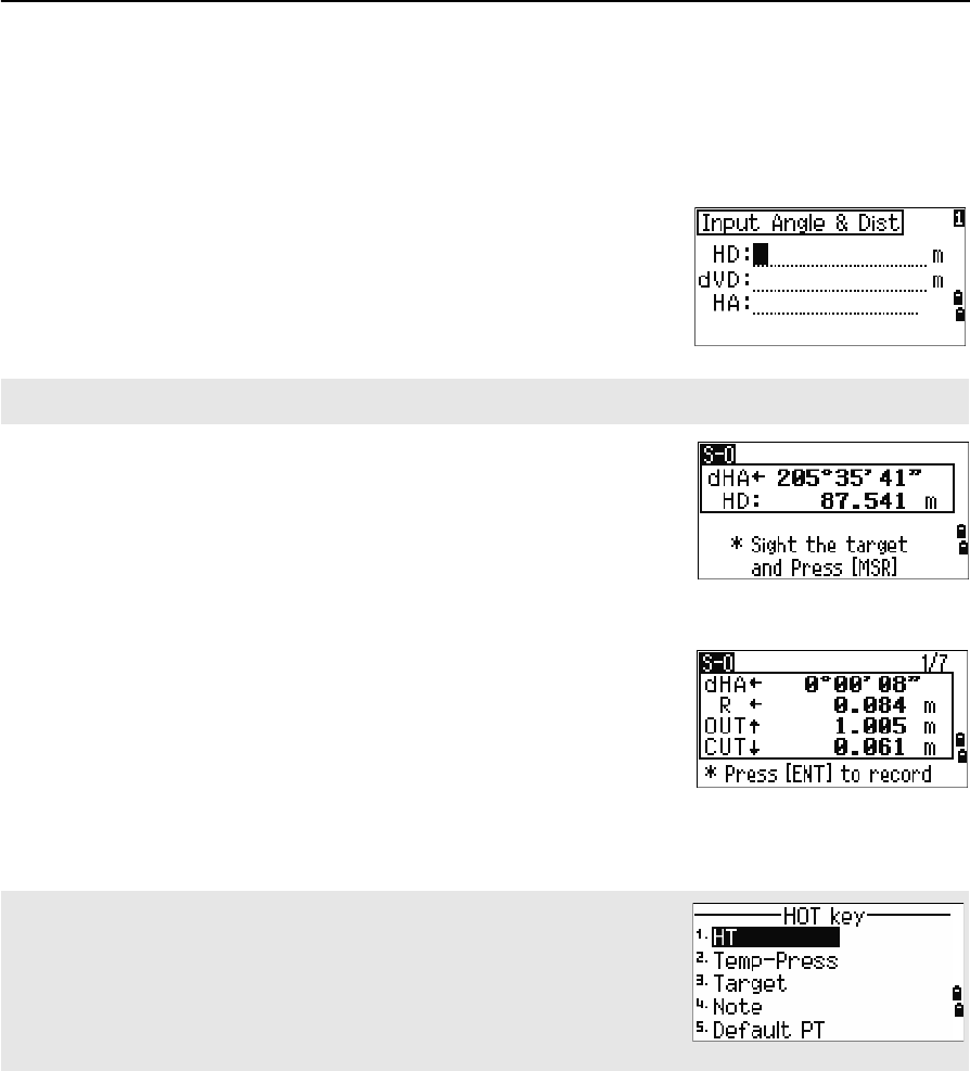
Total Station Nivo Series Instruction Manual 65
Applications 4
Specifying the stakeout point by angle and distance
1. To display the input screen for the distance and angle to the target, press [1] or
select HA-HD in the Stakeout menu.
2. Enter the values and press [ENT].
3. Rotate the instrument until the dHA is close to
0°00'00".
4. Sight the target and press [MSR1] or [MSR2].
When the measurement is completed, the
differences between the target position and the
stakeout point are displayed.
Once a measurement is taken, the Cut/Fill value and Z coordinate are updated
as the VA is changed.
HD Horizontal distance from station point to stakeout
point
dVD Vertical distance from station point to stakeout point
HA Horizontal angle to stakeout point
If you press [ENT] without entering HA, the current HA is used.
dHA Difference in horizontal angle to the target point
R/L Right/Left (Lateral error)
IN/OUT In/Out (Longitudinal error)
CUT/FILL Cut/FilL
If you press [HOT] in any observation screen, the HOT key menu appears. You
can use this menu at any time to change HT and T-P.
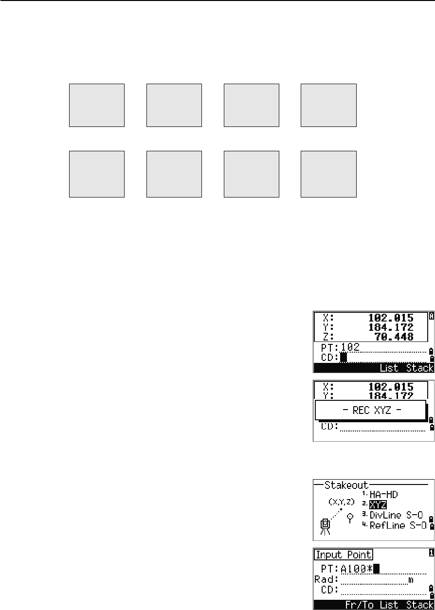
4 Applications
66 Total Station Nivo Series Instruction Manual
Using [DSP] to switch between display screens
Press [DSP] to switch between the Stakeout display screens. The following screens are
available:
The S-O8 screen is only available if the secondary distance unit is set. For more
information, see Others settings, page 112.
Every time you press [DSP], the next screen appears. If you press [DSP] in the last screen
(S-O7, or S-O8 if the secondary distance unit is set), the S-O1 screen appears.
To customize the S-O2, S-O3, and S-O4 screens, hold down [DSP] for one second. For
more information, see Customizing items in the Basic Measurement Screen (BMS),
page 31.
To record the stakeout point, press [ENT]. PT defaults to
the last recorded PT+1.
Press [ENT] to record the point.
After recording the point, it returns to the observation
screen. You can continue observation, or press [ESC] to
input another angle and distance for stakeout.
Specifying the stakeout point by coordinates
1. To start a stakeout by coordinates, press [2] or
select XYZ in the Stakeout menu.
2. Enter the point name that you want to stake and
press [ENT].
You can also specify the point by code or radius
from the instrument.
S-O1 S-O2 S-O3 S-O4
dHA←
R←
OUT↑
CUT↑
HA
VA
SD
HA
VD
HD
HL
V%
HD
S-O5 S-O6 S-O7 S-O8
X
Y
Z
dX
dY
dZ
rSD
rVD
rHD
HD
VD
SD
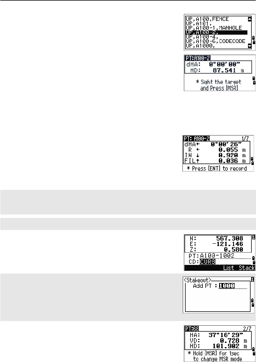
Total Station Nivo Series Instruction Manual 67
Applications 4
If several points are found, they are displayed in
a list. Use [^] or [v] to move up and down the list.
Use [<] or [>] to move up or down one page.
3. Highlight a point in the list and press [ENT].
The delta angle and the distance to the target are
shown.
4. Rotate the instrument until the dHA is close to
0°00'00". Press [MSR1] or [MSR2].
5. Ask the rodman to adjust the target position.
When the target is on the intended position, the
displayed errors become 0.000 m (or 0.000 ft).
6. To record the point, press [ENT]. PT defaults to the
specified PT + 1000.
After recording the point, the display returns to the
observation screen. When you press [ESC], the display
returns to the PT/CD/R input screen. If you entered the
stakeout point using a single point name, the PT
defaults to the last PT + 1.
dHA Difference in horizontal angle to the target point
HD Distance to the target point
dHA Difference in horizontal angle to the target point
R/L Right/Left (Lateral error)
IN/OUT In/Out (Longitudinal error)
CUT/FILL Cut/FilL
To switch between display screens, press [DSP]. This function works as in the angle-distance stakeout, except
that the screen counter (for example, S-O1/8) is not displayed. For more information, see Using [DSP] to switch
between display screens, page 66.
Once a measurement is taken, the Cut/Fill value and Z coordinate are updated as the VA is changed.
Use the Add Constant field in MENU > Settings > Stakeout to
specify an integer that is added to the point number being staked to generate
a new number for recording the staked point. The default value is 1000. For
example, when you stake out PT3 with an Add Constant of 1000, the default
number for SO record is 1003. For more information, see Stakeout, page 111.
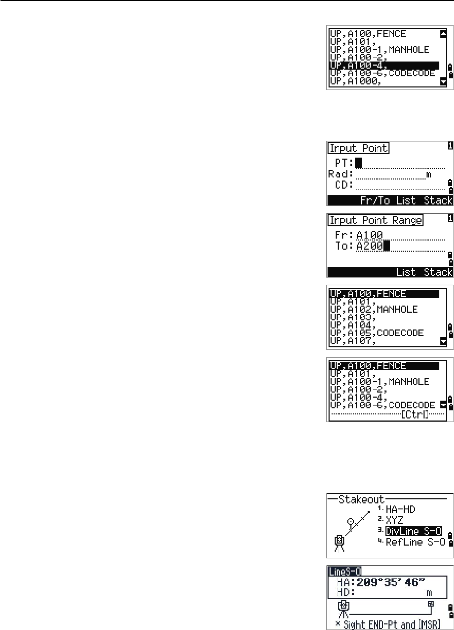
4 Applications
68 Total Station Nivo Series Instruction Manual
If you selected a point from the list, the display returns
to the list, unless all points have been selected. Press
[ESC] to return to the point input screen.
Advanced feature: Specifying a stakeout list by range input
1. To input points by range, press the Fr/To
softkey in the PT field.
2. Enter the start point (Fr) and the end point (To).
The range between Fr and To must be less than
1001 points.
If existing points are found between Fr and To, a
point list appears.
To highlight a point, press [^] or [v]. To go to the
stakeout observation screen, press [ENT].
If you have assigned a control job, and
additional points are found in the control job, the
Ctrl softkey appears under the list.
DivLine S-O
This function divides the line between the instrument and the first target by an input
span number. It then guides you to stake out the points, one by one.
1. Press [3] or select DivLine S-O in the Stakeout
menu.
2. Set up the baseline. To do this, sight the target on
the line (the end point) and press [MSR1] or [MSR2].
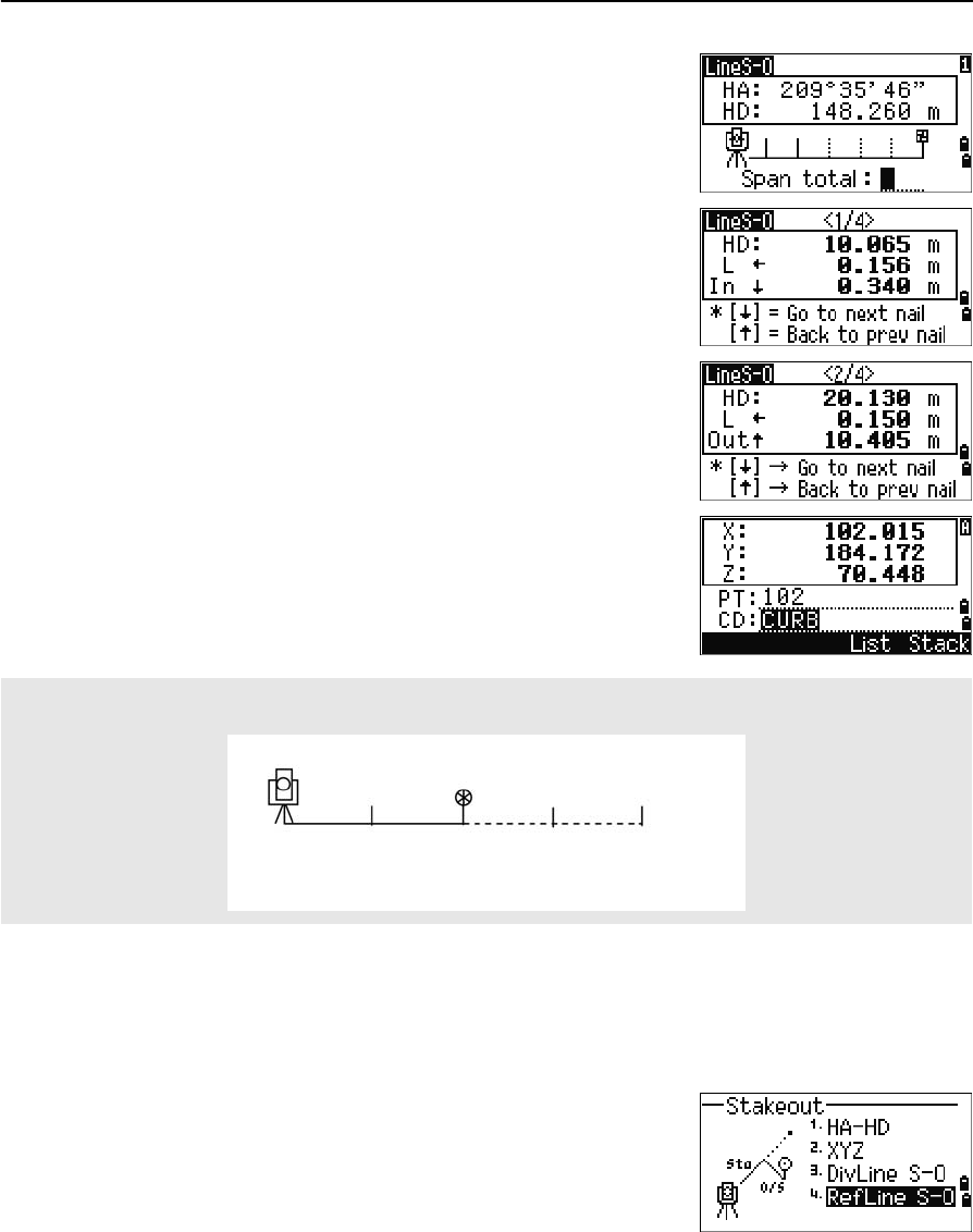
Total Station Nivo Series Instruction Manual 69
Applications 4
3. Enter the total stake number in the Span total
field.
The observation screen for the first stake (from
the instrument) appears.
4. Sight the prism and press [MSR1] or [MSR2].
5. Use [^] or [v] to change the guide point. You can
calculate and guide up to double the number of
the stakes.
6. To record the point as an SO record, press [ENT].
RefLine S-O
This function allows you to stake out a point based on the Sta, O/S, and dZ to a
specified line.
1. Press [4] or select
RefLine S-O in the Stakeout menu.
For example, if you measure to the end point at 100 m from the instrument and set the span total to 2, the
following four points are calculated and can be staked:
<1/2>
HD
<2/2> <3/2> <4/2>
50 m 100 m 150 m 200 m
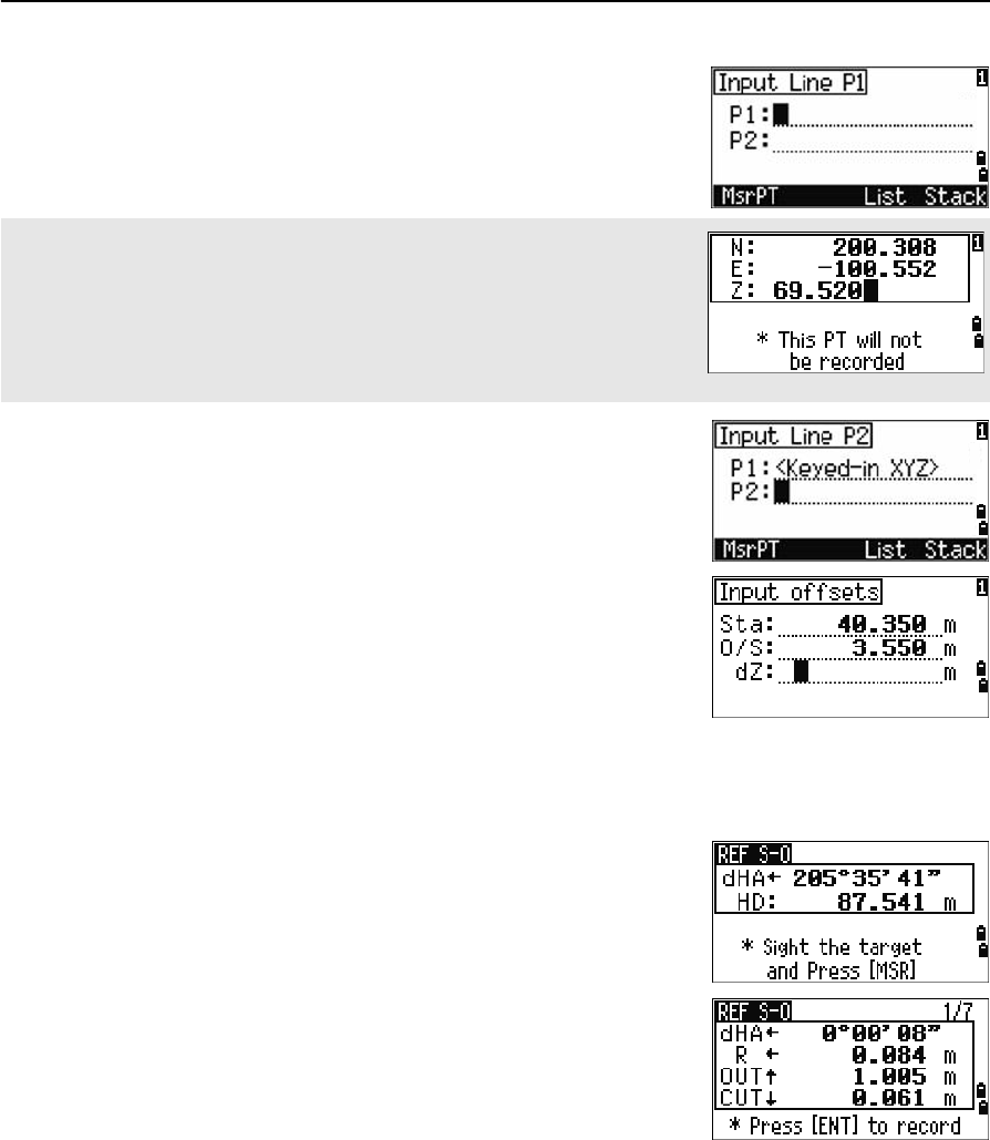
4 Applications
70 Total Station Nivo Series Instruction Manual
2. Enter the first point (P1) of the line.
3. Enter the second point (P2) of the line.
4. Enter offsets to the line.
Press [ENT] in a blank field to enter the value
0.0000.
5. Rotate the instrument until the dHA is close to
0°00'00".
6. Sight the target and press [MSR1] or [MSR2].
When a distance measurement is taken, the
difference from the design point appears.
7. To record the point as an SO record, press [ENT].
Using [DSP] to switch between display screens
You can use [DSP] to switch between display screens. This function works as in the
angle-distance stakeout. For more information, see Using [DSP] to switch between
display screens, page 66.
If you press [ENT] without entering a PT name, you can enter temporary
coordinates which are not recorded in the job.
Alternatively, press the MSR softkey to measure a point.
Sta Distance from P1 along the line
O/S Distance perpendicular to the line
(+) Right side of the P1-P2 line
(-) Left side of the P1-P2 line
dZ Difference in height from the line
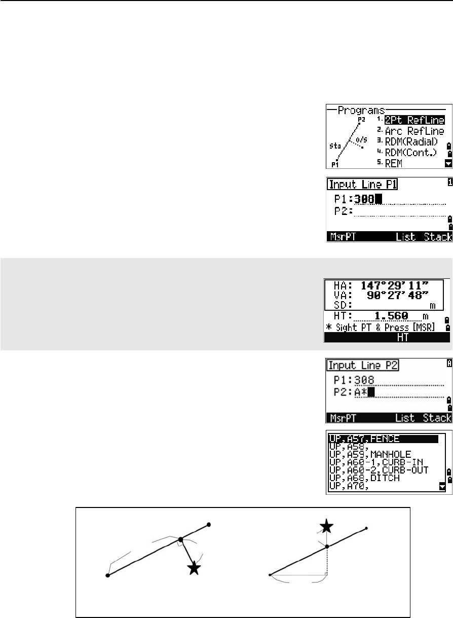
Total Station Nivo Series Instruction Manual 71
Applications 4
Program Key
To display the Programs menu, press [PRG].
Measuring distance and offset values along a specified line
1. Press [1] or select 2Pt RefLine in the
Programs menu.
2. Enter the first point for the reference line.
Alternatively (to enter the point by measuring),
press the MsrPT softkey.
3. Enter the second point for the reference line.
4. Enter an asterisk (*) in the PT field to perform a
wildcard search. A list of matching points
appears. Highlight a point in the list and then
press [ENT].
Direct Measurement screen
Press the MsrPT softkey to display a direct measurement screen.
Sight the target and press [MSR1] or [MSR2]. The Record PT screen appears.
If you press [ESC] in the Record PT screen, the measured point is used but
not recorded in the job.
Plain view Side view
PT1
PT2
Sta O/S
Prism
Prism
PT2
Sta
PT1
dZ
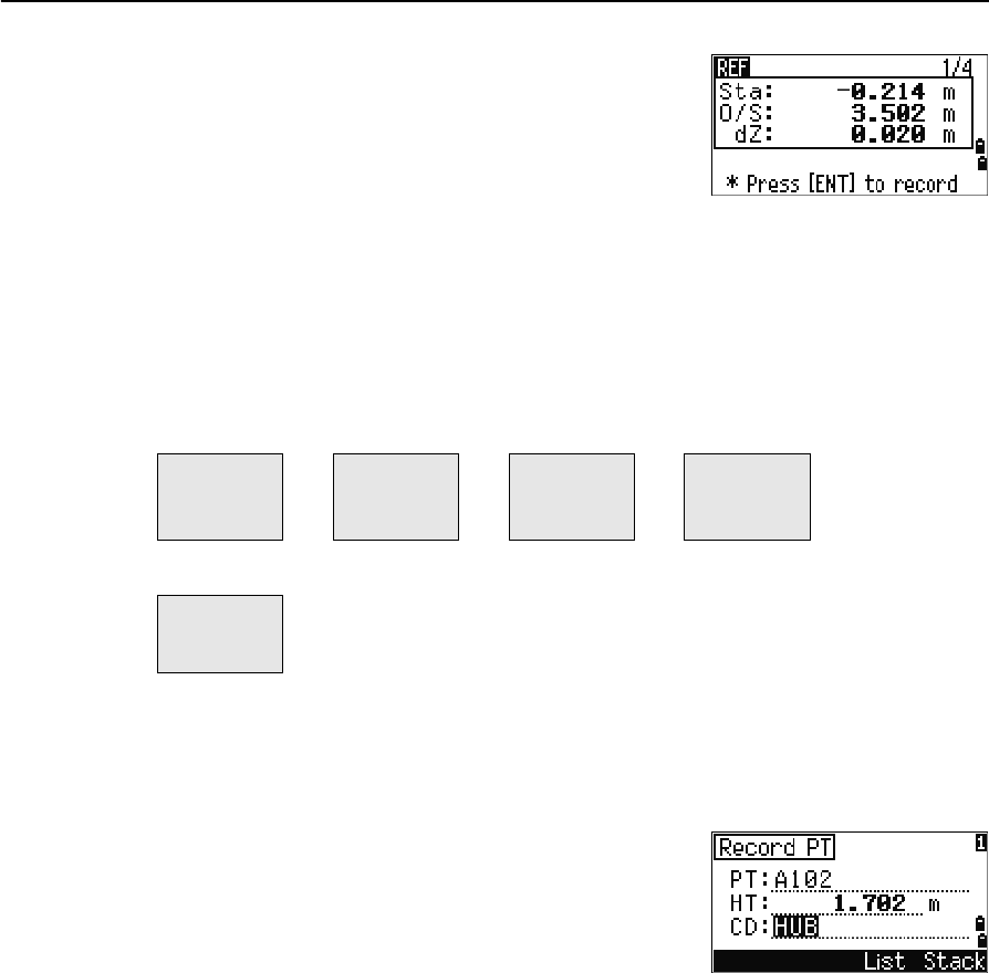
4 Applications
72 Total Station Nivo Series Instruction Manual
5. Sight the prism or reflective sheet and press
[MSR1] or [MSR2].
Using [DSP] to switch between display screens
Press [DSP] to switch between the Stakeout display screens. The following screens are
available:
The REF5 screen is only available if the secondary distance unit is set. For more
information, see Others settings, page 112.
Every time you press [DSP], the next screen appears. If you press [DSP] in the last screen
(REF4 or REF5), the REF1 screen appears.
To store the point and its offset distance information,
press [ENT].
Enter the point name and feature code.
You can also use this screen to change the HT value.
Sample records
CO, 2pt-Ref Pt:16 & Pt:13 Az:311.2932
CO, Sta= -12.6876 Offset= 1.3721 dZ= 0.0971
SS,17,1.0000,6.9202,18.4700,80.3120,15:48:48,2REF-LINE
Sta Horizontal distance from P1 to the measure point
along the P1-P2 line
O/S Horizontal offset from the P1-P2 line to the
measured point
dZ Vertical offset from the P1-P2 line to the measured
poin
REF1 REF2 REF3 REF4
Sta
O/S
dZ
X
Y
Z
HA
VA
SD
HA
VD
HD
REF5
HD
VD
SD
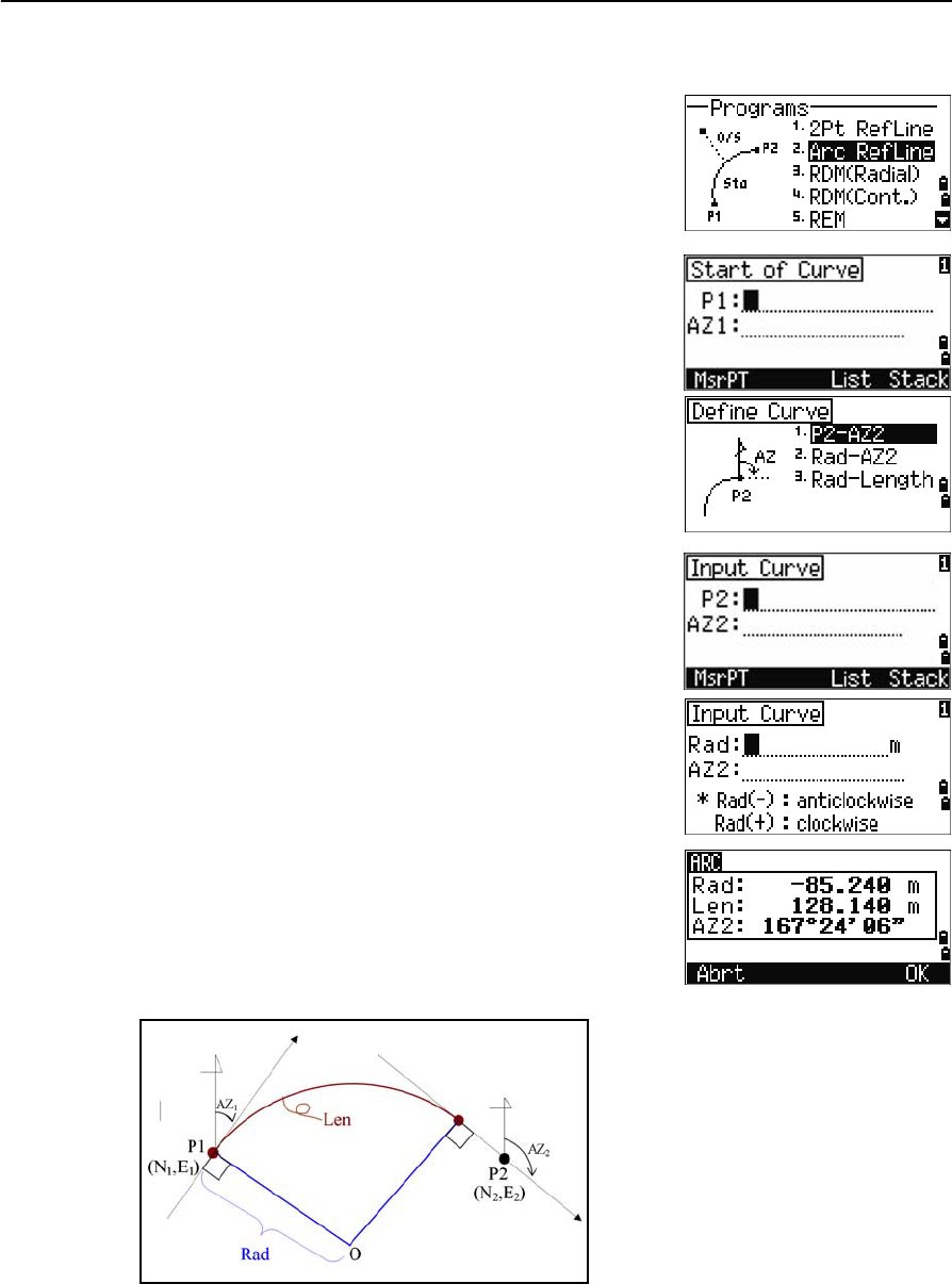
Total Station Nivo Series Instruction Manual 73
Applications 4
Measuring distance and offset values on the arc-curve
1. Press [2] or select Arc RefLine in the
Programs menu.
2. Enter the start of the curve point (P1) and the
azimuth of its tangent line (AZ1).
3. To enter P1 by direct measurement, press the
MSR softkey.
4. Choose a method to define the arc.
P2 can be any point on the tangent line that is to
exit the curve.
5. In the radius (Rad) field, enter a positive value
for a clockwise curve. Enter a negative value for
a counterclockwise curve.
When all factors have been entered, the instrument calculates the curve.
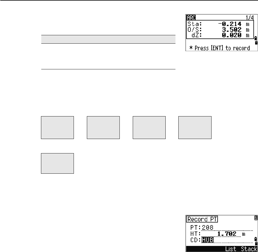
4 Applications
74 Total Station Nivo Series Instruction Manual
If the curve length (Len) is too large for a circle of the
given radius, it is shortened.
Using [DSP] to switch between display screens
Press [DSP] to switch between the Stakeout display screens. The following screens are
available:
The ARC5 screen is only available if the secondary distance unit is set. For more
information, see Others settings, page 112.
Every time you press [DSP], the next screen appears. If you press [DSP] in the last screen
(ARC4 or ARC5), the ARC1 screen appears.
To record the point, press [ENT] on any observation
screen. The arc is stored in comment records.
Sample records
CO,Arc P1:583 AZ1=0.0000 P2:102
CO, AZ2=311.2932 Radius=50.0000 Length=125.6637
CO, Sta= -12.6876 Offset= 1.3721 dZ= 0.0971
SS,17,1.0000,6.9202,18.4700,80.3120,15:48:48,2REF-LINE
To ... Press ...
switch between display screens [DSP]
change HT [HOT]
record points [ENT]
ARC1 ARC2 ARC3 ARC4
Sta
O/S
dZ
X
Y
Z
HA
VA
SD
HA
VD
HD
ARC5
HD
VD
SD
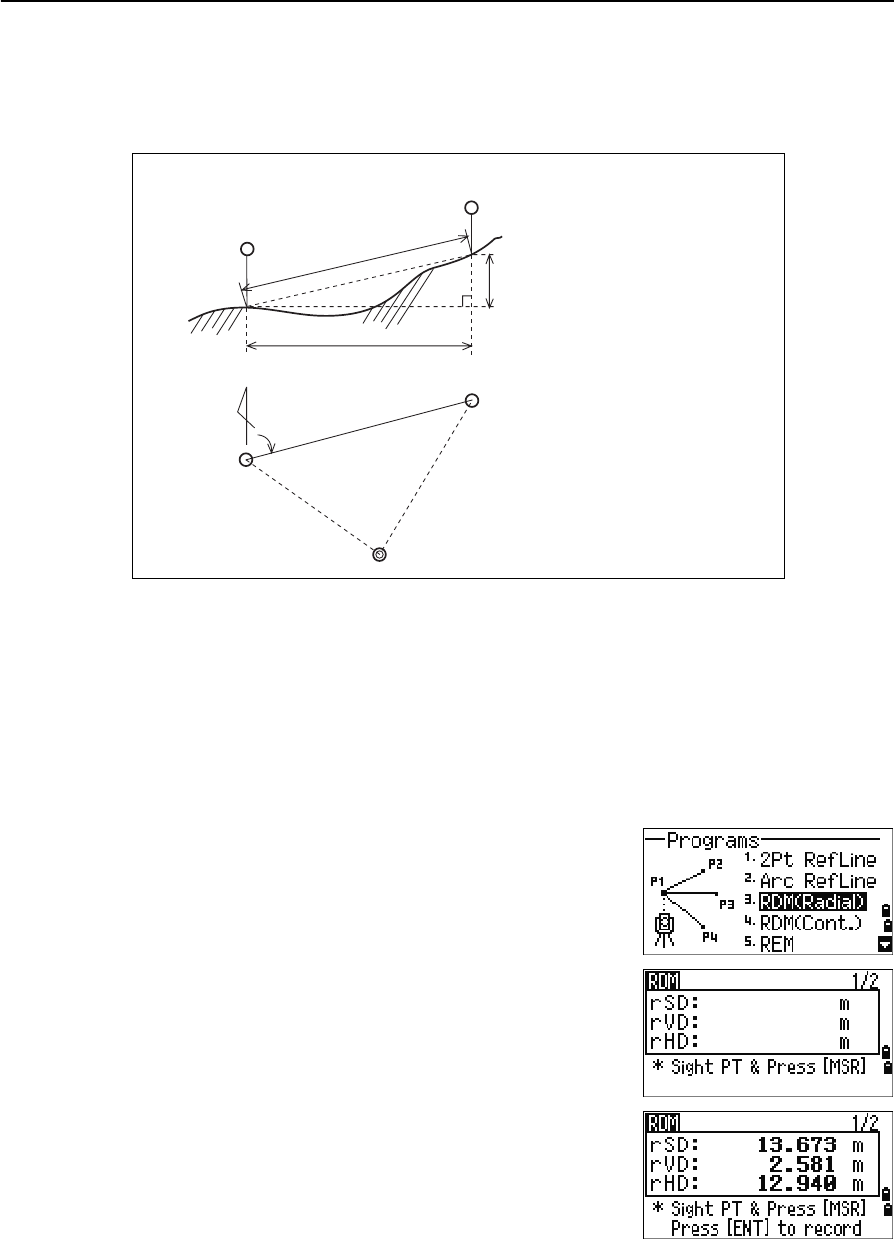
Total Station Nivo Series Instruction Manual 75
Applications 4
Remote distance measurement
This function measures the horizontal distance, vertical distance, and slope distance
between two points.
Measuring between the current and the first point measured
1. To enter the RDM (Radial) function, press [3] or
select RDM(Radial) in the Programs menu.
2. Sight the first point and press [MSR1] or [MSR2].
The distance from the station point to the first
point appears.
rSD Slope distance between two points
rHD Horizontal distance between two points
rVD Vertical distance between two points
rV% Percentage of grade (rVD/rHD) × 100%
rGD Vertical grade (rHD/rVD) :1
rAZ Azimuth from first point to second point
1st sighting
point
rSD
2nd sighting point
rVD
rHD
Horizontal angle 0 direction
rHA
2nd sighting point
Station point
1st sighting
point
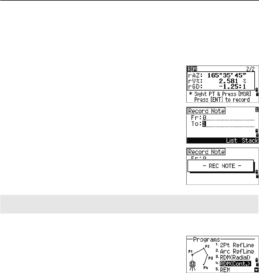
4 Applications
76 Total Station Nivo Series Instruction Manual
3. Sight the second point and press [MSR1] or [MSR2].
The distances between the first and second point
are displayed.
4. To change display screens, press [DSP].
5. To record the distance and angle information as
a comment record, press [ENT] in the 1/2 or 2/2
observation screen.
Default point numbers are displayed. You can
change these point numbers. To record a note,
press [ENT] in the To field.
Measuring between the current point and the immediately preceding point
1. To enter the RDM (Continuous) function, press
[4] or select RDM(Cont.)in the Programs menu.
2. Follow the procedure as for a radial RDM
measurement. For more information, see
Measuring between the current and the first
point measured, page 75.
rSD Slope distance between two points
rVD Vertical distance between two points
rHD Horizontal distance between two points
rAZ Azimuth from first point to second point
rV% Percentage of grade (rVD/rHD) × 100%
rGD Vertical grade (rHD/rVD) :1
Data that you save in RDM functions is stored in RM records. For more information, see RM records, page 116.
When you download data in Nikon RAW format, they are output as comment (CO) records.
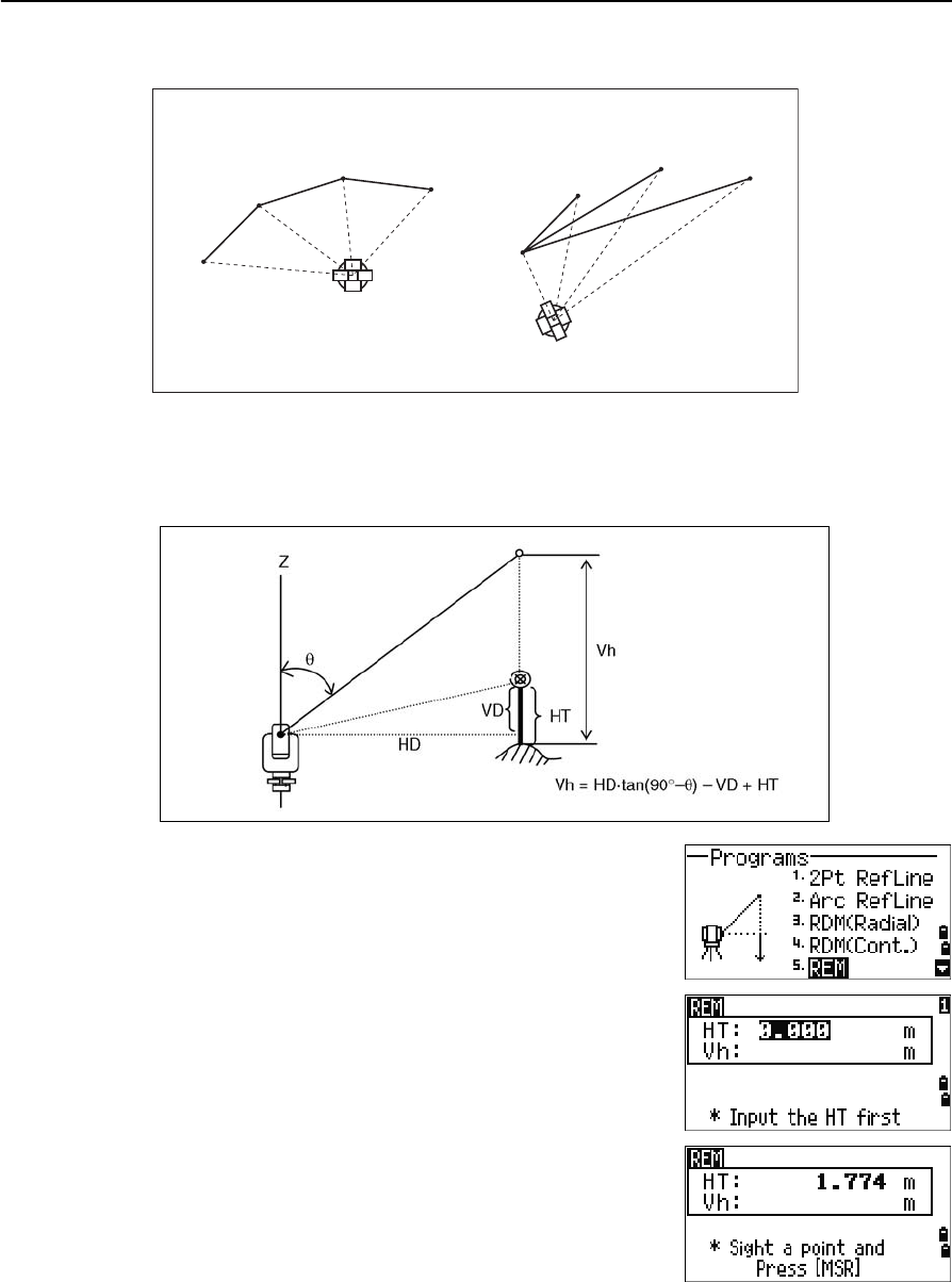
Total Station Nivo Series Instruction Manual 77
Applications 4
Measuring remote elevation
1. To enter the Remote Elevation Measurement
function, press [5] or select REM in the Programs
menu.
2. Enter the height of target.
3. Sight the target point and press [MSR1] or [MSR2].
Difference between “1:Cont.” and “2:Radial”
P1
P2
P3 P4 P3 P4
P2
P1
1:Cont.
(The preceding two points are
subject to calculation.)
2:Radial.
(Calculations are made with
reference to the first point.)
A prism is required
only at the sighting
(target) point
Station point
Sighting point
Arbitrary point
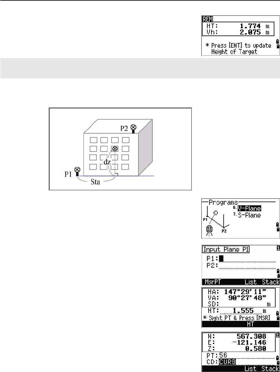
4 Applications
78 Total Station Nivo Series Instruction Manual
4. Loosen the vertical clamp, and turn the telescope
to aim at an arbitrary point.
The difference in elevation (Vh) appears.
Measuring distance and offset values on the vertical plane
1. To enter the 2-Pt Reference Plane function, press
[6] or select
V-Plane in the Programs menu.
2. Enter two points to define the plane.
To enter the point by direct measurement, press
the MsrPT softkey.
When you press the MSR softkey, a temporary
observation screen appears.
3. Press [MSR1] or [MSR2]. The Record PT screen
appears.
4. Enter a value in the PT and CD fields. Press [ENT].
You can use an REM measurement to update the height of target. Take a measurement to the prism, sight the
bottom of the prism pole, and press [ENT].
Baseline
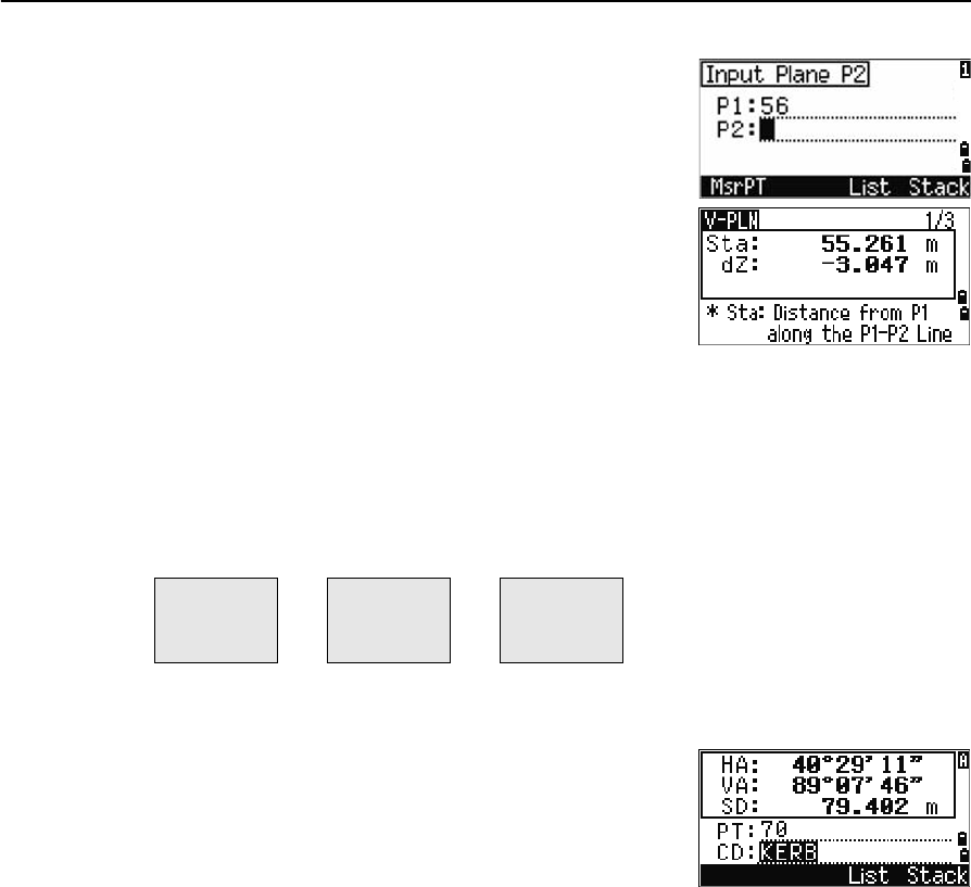
Total Station Nivo Series Instruction Manual 79
Applications 4
5. Enter the second point on the vertical plane.
Press [ENT].
Once the plane is defined, the calculated Sta and dZ
values are updated as you move the telescope. No
distance measurement is required.
Using [DSP] to switch between display screens
Press [DSP] to switch between the plane display screens. The following screens are
available:
Every time you press [DSP], the next screen appears. If you press [DSP] in the last screen
(PLN3), the PLN1 screen appears.
To record the point, press [ENT] on any screen (V-
PLN1/3 to V-PLN3/3).
Enter PT and CD. Then press [ENT].
Sample records
CO,Vertical Ref Plane Pt1:516-A1 Pt2:530
CO,Sta=68.021 dz=17.459
SS,30123-A48,1.5480,16.4020,40.4720,89.0730,14:22:47,
Sta Horizontal distance from P1 to the target
point along the baseline
dZ Vertical distance from P1 to the target
point
PLN1 PLN2 PLN3
Sta
dZ
X
Y
Z
HA
VA
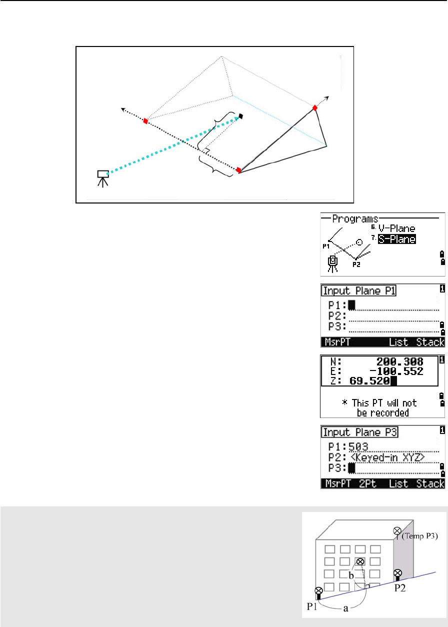
4 Applications
80 Total Station Nivo Series Instruction Manual
Measuring distance and offset values on the slope
1. To enter the 3-Pt Reference Plane function, press
[7] or select
S-Plane in the Programs menu.
2. Enter three points to define the slope plane. To
enter the point by direct measurement, press the
MSR softkey.
If you press [ENT] in a blank field, an input screen
for temporary coordinates appears. These
coordinates will not be stored.
When you have entered the temporary
coordinates, <Keyed-in XYZ> appears
instead of the PT name.
If the plane is defined by two points (by selecting 2Pt), the vertical
plane is the same as the plane used in the V-Pln function, but the
indicating factors are Sta and dZ, not a and b. For more information, see
Measuring distance and offset values on the vertical plane, page 78.
Stn
P2
(X2,Y2,Z2)
P1
(X1,Y1,Z1)
P3
(X3,Y3,Z3)
Ta r g e t
(X,Y,Z)b
a
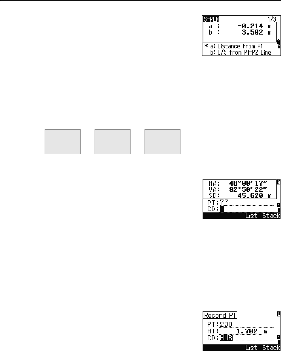
Total Station Nivo Series Instruction Manual 81
Applications 4
Once the plane is defined, the calculated a and b
values are updated as you move the telescope.
No distance measurement is required.
Using [DSP] to switch between display screens
Press [DSP] to switch between the plane display screens. The following screens are
available:
Every time you press [DSP], the next screen appears. If you press [DSP] in the last screen
(PLN3), the PLN1 screen appears.
To record the point, press [ENT] on any screen
(S-PLN1/3 to S-PLN3/3).
Enter PT and CD. Then press [ENT].
Sample records
CO,3ptPlane P1:1062 P2:2902 P3:1547
CO,a=31.497 b=14.239
SS,30123-A49,1.6110,0.0000,234.3210,86.0955,16:07:18,
Recording Measurement Data
Recording data from any observation screen
To record points on observation screens, press [ENT].
PT defaults to the last recorded PT + 1.
You can enter the PT name from the point list or the
point stack. For more information, see Entering a point
from the point list, page 42, and Entering a point from
the stack, page 42.
You can also use the code list or the code stack. For more information, see Entering a
code from the code list, page 43, and Entering a code from the stack, page 43.
a Distance between P1 and the point that is
perpendicular to the target point along the P1-
P2 line
b Length of the perpendicular line from the target
point to the P1-P2 line
PLN1 PLN2 PLN3
a
b
X
Y
Z
HA
VA

4 Applications
82 Total Station Nivo Series Instruction Manual
To record the point, press [ENT] on the last field.
When recording sideshots, stakeout records and
control shots from the Rept function, you can choose to
store raw data only, XYZ data only, or both. For more
information, see Recording, page 112.
Hold down [ENT] for one second to record the
measurement as a CP record.
Outputting data to the COM port
If you press [ENT] while the [COM] icon appears in an
observation screen, a line of data is output to the COM
port.
Note – If [COM] appears, data is not stored to the job when you press [ENT].
The format of the output data is defined by the setting
of the Ext.Comm field in MENU > Settings >
Comm. For more information, see Communications,
page 111.
If HA or VA is moved after you take a measurement but before you press [ENT], the angle recorded is the angle
shown when [ENT] is pressed.
In an angle-only record, SD is always recorded as 0.0000.
If the point name that you want to record already exists in the job, an error
message appears. Depending on the type of existing record, you can
overwrite the old record with the new data. For more information, see
Recording Data, page 173.
To output data on the COM port when you press [ENT], set the Data Rec field in
MENU > Settings > Rec to COM. For more information, see
Recording, page 112.
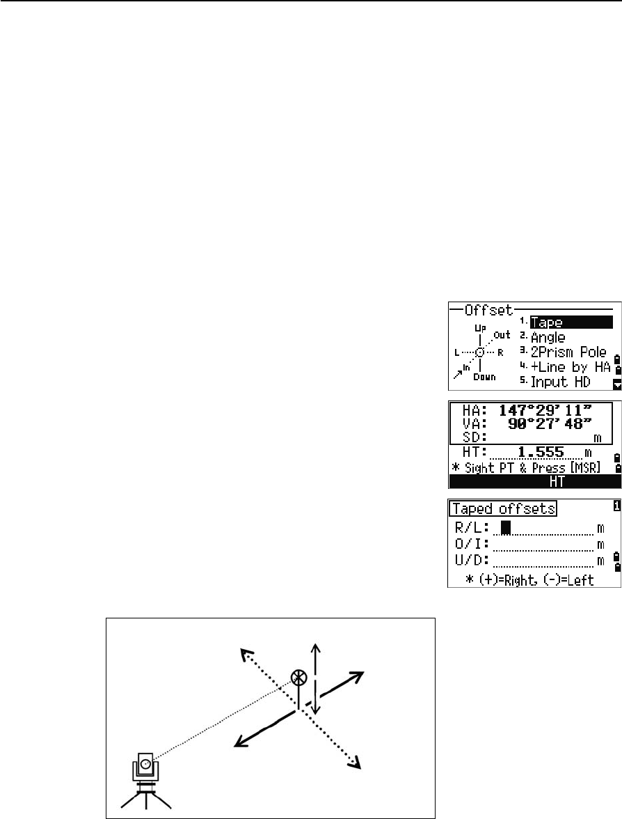
Total Station Nivo Series Instruction Manual 83
Applications 4
Sample output records through COM port
When the Ext.Comm field is set to NIKON:
TR PN: PT8 SD:000066626 HA:003856010 VA:008048500 HT:0000061757
(TR PN: point name SD HA VA HT; when ACK is returned, PN is incremented.)
When the Ext.Comm field is set to SET:
0006662 0804806 0394324 97
(SD VA HA Chk-SUM)
Measuring Offsets
Measuring taped offsets
1. To enter the taped offset function, press [1] or
select Tape in the Offset menu.
If you have not taken a distance measurement
before entering this function, a temporary
measurement screen appears.
2. Sight the target and press [MSR1] or [MSR2].
3. Enter offset distances from the measured point.
Use [^] or [v] to move to the appropriate offset
field.
Left (-)
In (-)
Up (+)
Out (+)
Down (-)
Right (+)
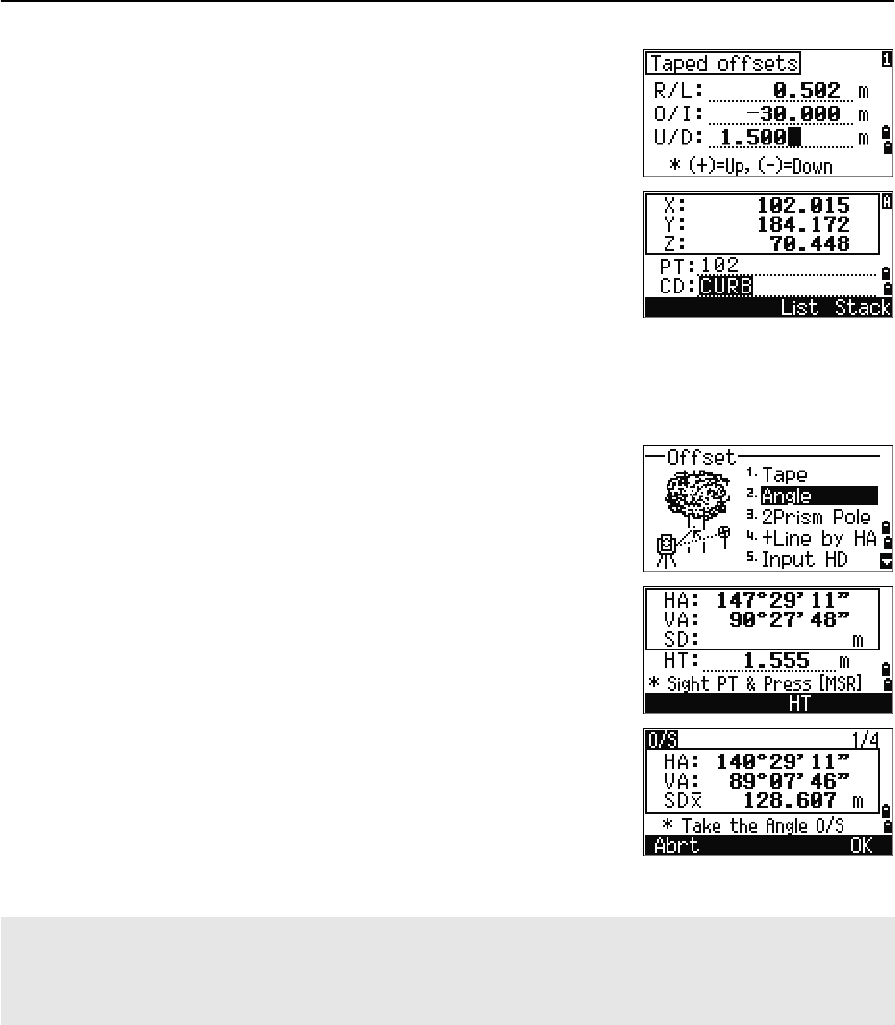
4 Applications
84 Total Station Nivo Series Instruction Manual
You can enter any combination of taped offset
distances to specify the point.
4. To go to the recording PT screen, press [ENT] in
the last field.
The calculated coordinates are shown.
5. Enter a PT (and CD) value.
6. Press [ENT] to record the point.
Raw data is also recalculated, based on the taped
offset value.
Measuring angle offsets
1. To enter the angle offset function, press [2] or
select Angle in the Offset menu.
If you have not taken a distance measurement
before entering this function, a temporary
measurement screen appears.
2. Sight the target and press [MSR1] or [MSR2].
3. To take the angle offset, rotate the alidade and
telescope. The measured distance (HD) remains
unchanged.
4. To record the offset point, press [ENT] or the OK
softkey.
The XYZ data is also recalculated, based on the new angle.
You can record an angle offset in the Basic Measurement Screen (BMS). After taking a distance measurement,
rotate the alidade and/or telescope. Then press [ENT] to record the measured distance with the updated angle
value. If you use this method, the dimension of the angle offset is not stored as a CO record. To store the CO
record, use the O/S function.
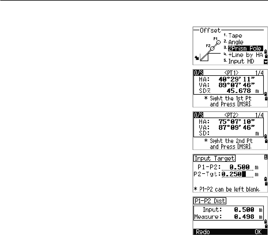
Total Station Nivo Series Instruction Manual 85
Applications 4
Two-prism pole
1. To enter the two-prism pole function, press [3] or
select 2Prism Pole in the Offset menu.
2. Sight the first prism and press [MSR1] or [MSR2].
3. Sight the second prism and press [MSR1] or [MSR2].
4. Enter the distance between the second prism and
the target point. Alternatively, if you do not need
QA information, you can leave the distance
between the first and the second prism blank.
5. If you do enter a P1-P2 distance, the QA screen
appears. Compare the entered value and the
measured distance to check the accuracy of the
observation.
6. To record the point, press [ENT] or the OK softkey.
Sample records
SS,14,0.0000,38.9200,271.0350,89.2630,11:04:15,DITCH
CO,2Prism O/S: P1-P2= 0.5090( 0.5060) P2-Tgt= 0.5020
Note – In this sample data, 0.5090 is the measured value. 0.5060 is the entered value.
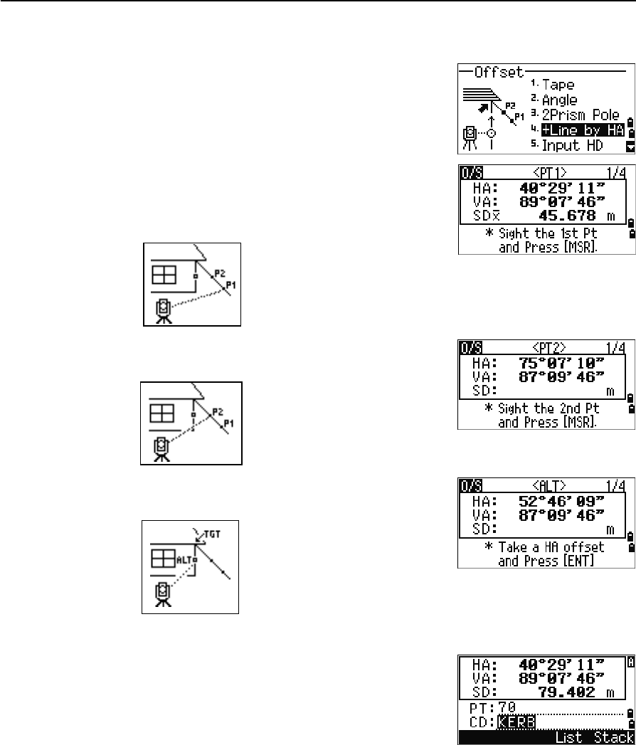
4 Applications
86 Total Station Nivo Series Instruction Manual
Extending a line by horizontal angle offset
1. To enter the line extension (by HA) function,
press [4] or select +Line by HA in the Offset
menu.
2. Sight the first prism (or target) and press [MSR1]
or [MSR2].
The display moves to the next screen.
3. Sight the second prism (or target) and press
[MSR1] or [MSR2].
4. Sight the alternative place on the same vertical
line as the required target point.
5. To calculate the coordinates and the raw data of the target point, press [ENT].
6. To record the point, enter a PT (and CD) value
and press [ENT]. The height of target is fixed to
0.0000 for the offset point.
Sample records
SS, 40, 0.0000, 48.3304, 169.20370, 82.02470, 10:52:37
CO, PT1, 0.0000, 48.3020,169.19165, 83.58565
CO, PT2, 0.0000, 48.3155,168.54250, 85.42440
CO, O/S MSR:40 0.0000 0.0000 169.20370 87.02340
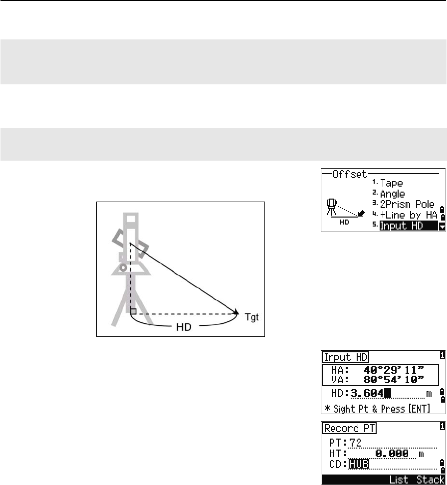
Total Station Nivo Series Instruction Manual 87
Applications 4
Entering a horizontal distance after an angle-only shot
1. To enter the Input HD function, press [5] or select
Input HD in the Offset menu.
2. Turn the telescope in the direction of the point
that you want to store.
3. Enter the HD. Usually this is the taped distance
from the instrument point.
4. Enter a PT (and CD) value and press [ENT].
The target point is calculated and recorded as an
SS record.
Sample records
SS,158,0.0000,77.0518,62.08380,108.06510,11:51:48,
CO, Input HD:76.1243
The calculated point (TGT) is stored as a SS record.
Measurements to the first and second target (P1 and P2) are stored as comment records (PT1 and PT2). The
last record records the angle measurement to the ALT (vertically offset point from the actual target point).
This function is useful when the instrument is very close to the point and it is difficult to take a measurement
using the EDM.
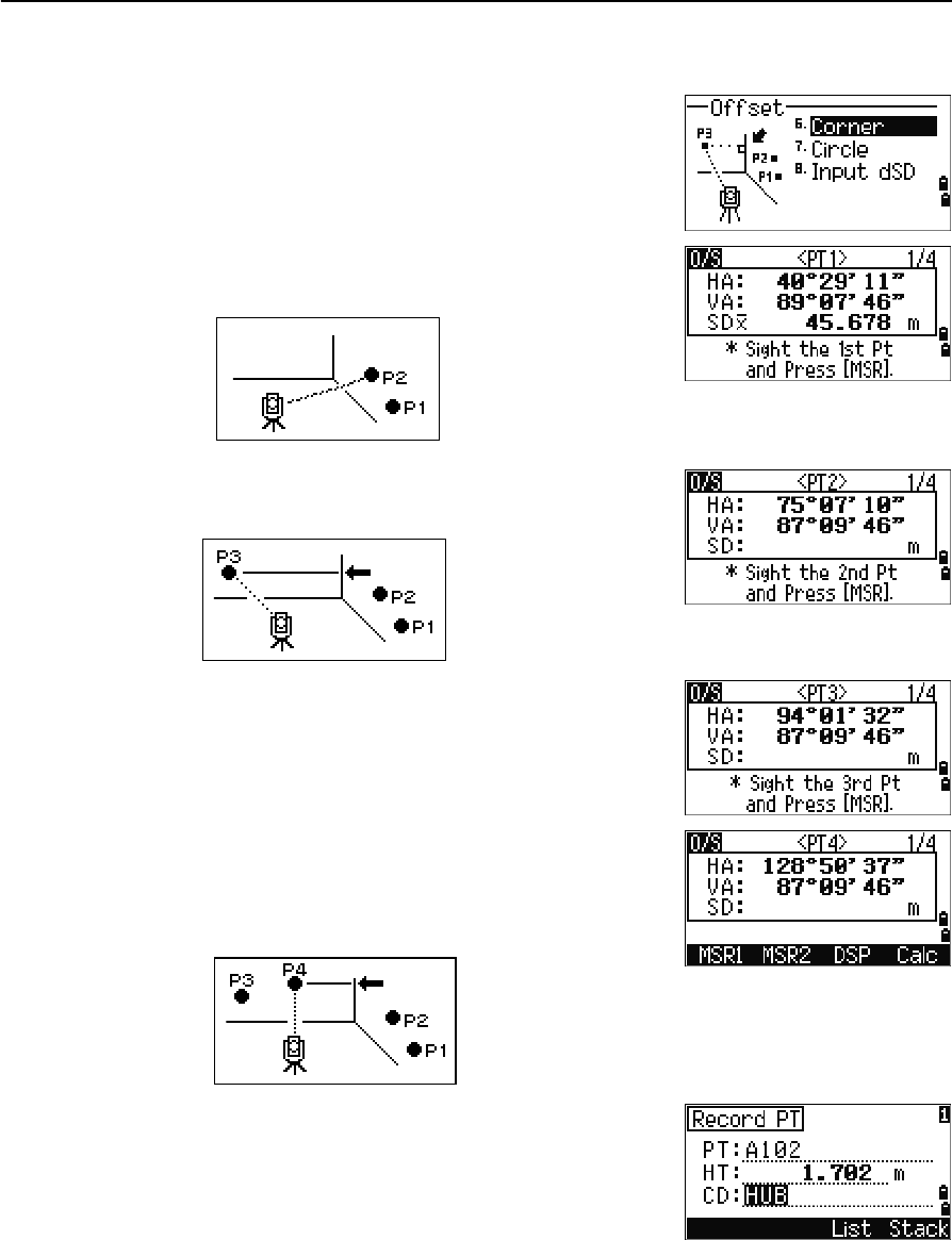
4 Applications
88 Total Station Nivo Series Instruction Manual
Calculating a corner point
1. To enter the corner point function, press [6] or
select Corner in the Offset menu.
2. Take a distance measurement to the first prism
(or target) on the wall. Press [MSR1] or [MSR2].
3. Sight a second point on the same wall with the
first point measurement. Press [MSR1] or [MSR2].
4. Sight the first point on the second wall. Press
[MSR1] or [MSR2].
5. If the two walls are at right angles, press the
Calc softkey to calculate the corner point by
three points.
6. If you take a measurement to a fourth point, the
corner point can be calculated as the intersection
of two walls (P1-P2 and P3-P4). The default
elevation is given by P4.
7. Enter a PT (and CD) value. The height of target
(HT) defaults to the value used in the last
measurement.
8. To record the corner point, press [ENT].
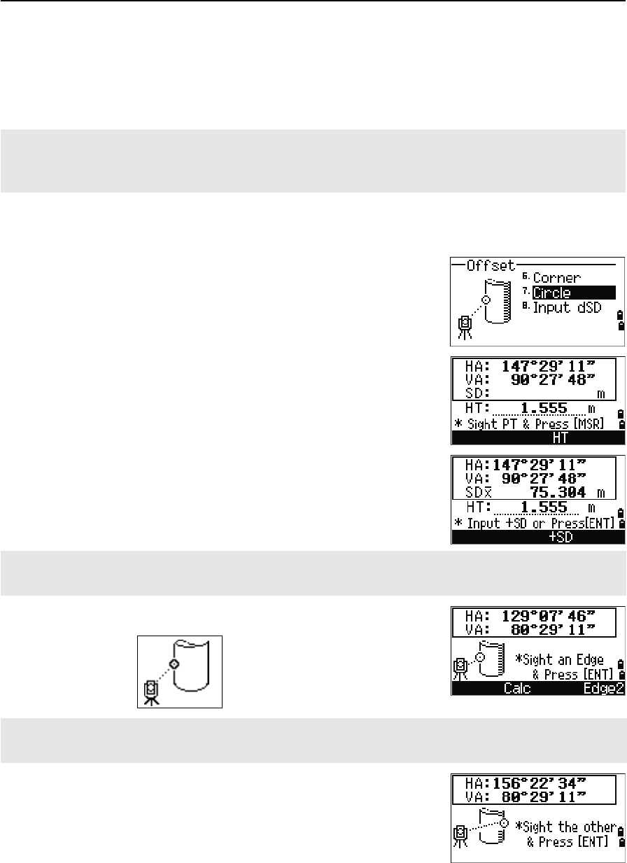
Total Station Nivo Series Instruction Manual 89
Applications 4
Sample records
SS, 58, 0.0000, 48.3304, 169.19165, 82.02470, 10:52:37, FLOOR2
CO, PT1, 1.0080, 48.3020,169.19165, 83.58565
CO, PT2, 1.0080, 48.3155,128.54250, 85.42440
CO, O/S MSR:40 0.0000 0.0000 169.20370 87.02340
Measuring circle offsets
1. To enter the circle center calculation function,
press [7] or select Circle in the Offset menu.
If you have not taken a measurement to the
circle before entering this function, a temporary
measurement screen appears.
2. Sight any point on the surface of the circle and
press [MSR1] or [MSR2].
3. Sight one edge of the circle and press [ENT].
4. Sight the other edge of the circle and press [ENT].
The calculated corner point is stored as an SS record.
The next three or four comment records are measured points. For example:
CO, Point name (fixed to PT1, PT2 etc.), HT, SD, HA, VA.
If you use a prism attached to the surface of the circle for the distance measurement, press the +SD softkey to
eliminate the offset error (from the attached point to the measured surface of the prism) before you press [ENT].
If you have taken a distance measurement to the center of the circle, press the Calc softkey to calculate the
offset using one edge angle observation.
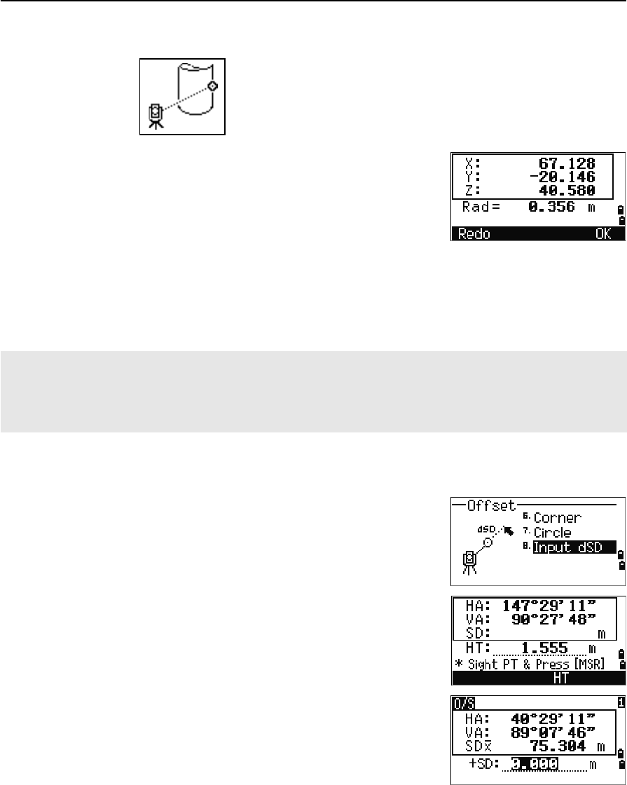
4 Applications
90 Total Station Nivo Series Instruction Manual
The instrument calculates and records the center of the circle.
It also calculates the coordinates of the center
point and the radius of the circle.
5. To record the point, press [ENT] or the OK softkey.
Sample records
SS,71,1.5000,37.0518,32.08380,81.06510,11:51:48,
CO, PT1, 0.0000, 0.0000,47.05350, 83.58560
CO, PT2, 0.0000, 0.0000, 29.53010, 83.58560
CO,O/S MSR:71 1.5555 36.5418 38.28360 81.06510
CO,Radius of circle 0.356
CO,Input +SD:0.0020
Extending the slope distance
1. To enter the function for extending the slope
distance, press [8] or select Input dSD in the
Offset menu.
If you have not taken a distance measurement
before entering this function, a temporary
measurement screen appears.
2. Enter the slope distance that you need to add or
subtract. You can enter any value from
–99.990 through +99.990 m (–328.000 through
+328.000 ft).
3. To record the point, press [ENT].
Sample records
SS,83,1.5000,77.0518,62.08380,81.06510,11:51:48,
CO,O/S MSR:83 1.5555 76.5518 62.08380 81.06510
The calculated point (center of the circle) is stored as an SS record.
The following one or two comment records are angle-measured points. For example:
CO, Point name (fixed to PT1/ PT2), HT(0.0000), SD(0.0000), HA, VA.
If you press the +SD softkey before you sight Edge1, the input value is recorded at the end.