NIKON TRIMBLE NT0001 Bluetooth module User Manual Focus4 manual 2 p
NIKON-TRIMBLE CO., LTD. Bluetooth module Focus4 manual 2 p
Contents
Host 1 user manual 2 of 4

CHAPTER
3
Spectra Precision Focus 4 Total Station User Guide 37
Getting Started 3
In this chapter:
QParts of the instrument
QInstrument keyboard and display
QTurning on the instrument
QTurning off the instrument
QRegional configuration
QList available jobs or data
QEntering data
QCreating or opening a job
QMeasuring distances
After you set up the instrument, see page 23, you
can start using the Focus 4 total station.
This chapter describes the basic features of the
instrument, how to turn it on, change the
instrument settings, and start a job.
3 Getting Started
38 Spectra Precision Focus 4 Total Station User Guide
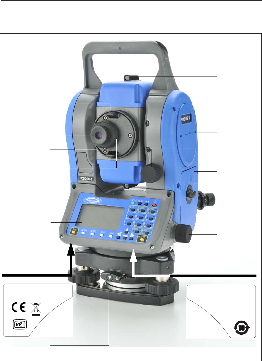
Parts of the instrument
Figure 3.1 and Figure 3.2 show the main parts of the Focus 4 total station.
Figure 3.1 Back view of the Focus 4 total station (Face 1)
Telescope
Telescope
Diopter ring
Carrying
Vertical tangent
Horizontal
screw
tangent screw
focusing ring
handle
eyepiece
Face 1 display and
keyboard
The laser safety label shown
below is attached to the
Optical sight
(finder)
Horizontal axis
indication mark
Battery box
Battery box
release knob
Reticle plate cover
Complies with 21 CFR 1040 . 10 and 1040 . 11
except for deviations pursuant to
Laser Notice No . 50 , dated June 24 , 2007
MADE IN JAPAN
Technoport Mitsuiseimei Bldg.
16
-
2,Minamikamata 2
-
chome,
Ota
-
ku, Tokyo 144
-
0035 Japan
NIKON
-
TRIMBLE CO.,LTD.
underside of the keyboard.
Tribrach clamp
knob
The label shown below is
attached to the underside
of the keyboard.
This device complies with Part 15 of the FCC Rules .
Operation is subject to the following two conditions :
1 this device may not cause harmful interference , and
2 this device must accept any interference received ,
including interference that may cause undesired operation.
Spectra Precision Focus 4 Total Station User Guide 39
Getting Started 3
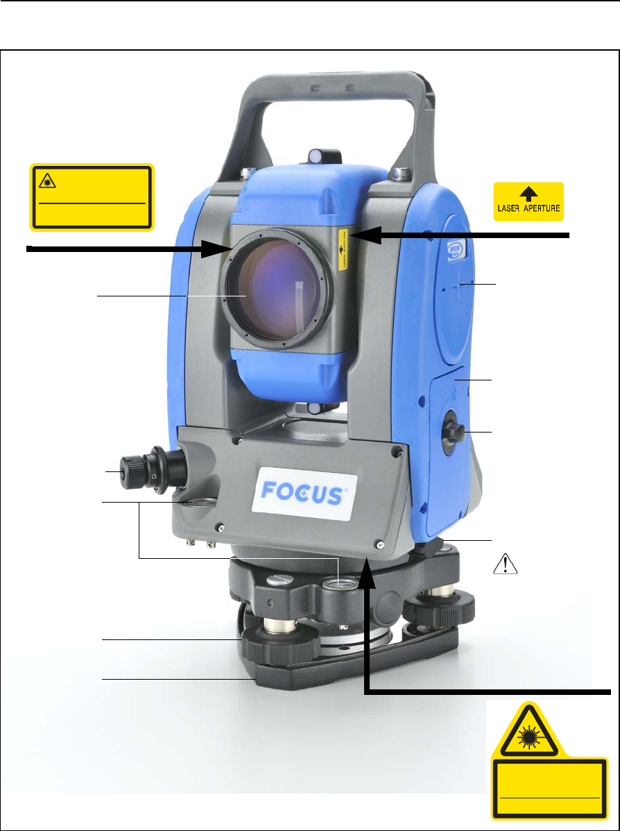
Figure 3.2 Front view of the Focus 4 total station (Face 2)
Objective
The laser safety label shown below
is attached to the side
LASER LIGHT IS
THIS PART
EMITTED FROM
Data output/
input connector
(input voltage
4.5-5.2 V DC)
Po
Ƀ
1mW CW
Ё
=630
-
690nm
Class 2 Laser Product
Do not stare into beam
Laser Radiation
IEC60825-1:2001
Optical plummet
of the telescope.
The laser safety label
shown below is
attached to the
telescope.
Horizontal axis
indication mark
Battery box
Battery box
release knob
external power
The laser safety label
shown below will be
attached here
ircular levelC
(underneath) when
the optional laser
plummet is used.
Po
<
1.0mW CW Ё=635nm
IEC 60825
-
1 ,2001
LASER RADIATION
DO NOT STARE INTO BEAM
CLASS 2 LASER PRODUCT
Leveling screw
Tribrach
(shown here) or
optional laser
plummet
3 Getting Started
40 Spectra Precision Focus 4 Total Station User Guide
Instrument keyboard and display
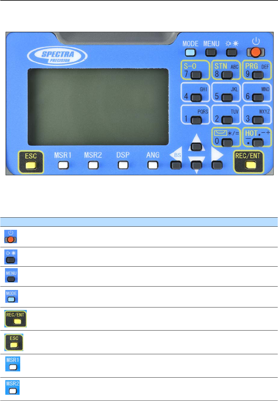
Instrument keyboard
Use the buttons on the instrument keyboard to carry out the following functions:
Button Function See ...
Turns the instrument on or off. page 48
Illumination button. Turns the backlight on or off.
Provides access to the switch window if held down for one second.
page 43
Displays the MENU screen. page 91
Changes the button input mode between alphanumeric and numeric if
pressed when you are in a PT or CD field.
page 46
Records measured data, moves on to the next screen, or confirms and accepts
the entered data in input mode.
page 89
Returns to the previous screen.
In numeric or alphanumeric mode, deletes input.
Starts distance measurement, using the measure mode settings for the [MSR1]
button.
Displays measurement mode settings, if held down for one second.
page 56
Starts distance measurement, using the measure mode settings for the [MSR2]
button.
Displays measurement mode settings, if held down for one second.
page 56
Spectra Precision Focus 4 Total Station User Guide 41
Getting Started 3
Status bar
The status bar appears on the right of every screen. It contains icons that indicate the
status of various system functions.
Moves to the next available display screen.
Changes the fields that appear on the DSP1, DSP2, and DSP3 screens, if held
down for one second.
page 44
Displays the Angle menu. page 60
Displays the Stakeout function menu.
In numeric mode, enters 7.
page 60
Displays the Station Setup menu.
In numeric mode, enters 8. In alphanumeric mode, enters A, B, C, or 8.
page 60
Displays the Programs menu.
In numeric mode, enters 9. In alphanumeric mode, enters D, E, F, or 9.
page 75
Displays the (HOT) menu, which includes Height of Target and Temp-Press
settings.
In numeric mode, enters – (minus). In alphanumeric mode, enters. (period), –
(minus), or + (plus).
page 46
Displays the Bubble indicator.
In numeric mode, enters 0. In alphanumeric mode, enters *, /, =, or 0.
page 47
Button Function See ...
Status bar
3 Getting Started
42 Spectra Precision Focus 4 Total Station User Guide
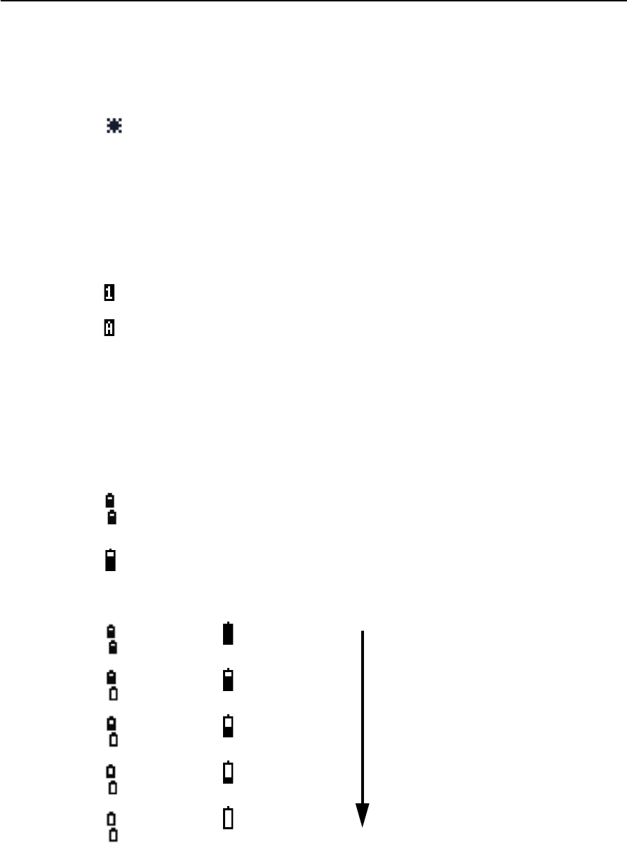
Laser-pointer indicator
The icon appears as you turn on the laser pointer. When the icon appears on the
screen, the emitting power is laser class 2.
If there is no icon, the laser pointer is off.
Input mode indicator
The input mode indicator appears only when you are entering points or coordinates. It
shows the data input mode:
Battery indicator
Shows each voltage level of the right and left internal batteries individually. When the
external battery is connected with the instrument, its voltage is shown.
Laser pointer ON
Input mode is numeric. Press a button on the number pad to enter the number
printed on the button.
Input mode is alphabetic. Press a button on the number pad to enter the first letter
printed beside the button. Press the button repeatedly to cycle through all the
letters assigned to that button.
For example, to enter the letter O in alphabetic mode, press [6] three times.
Internal batteries:
• Top: left battery
• Bottom: right battery
External battery
Internal batteries External battery
Battery level indication
Battery low
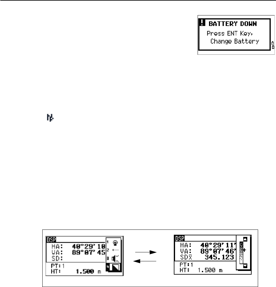
Spectra Precision Focus 4 Total Station User Guide 43
Getting Started 3
If the battery level is critically low, a message appears.
EDM measurement status
When you are taking measurements, the EDM measurement status shows the mode
that is being used.
When you display observation data, the EDM measurement status shows the mode
that was used when the data was collected:
If there is no icon, Prism mode is being used.
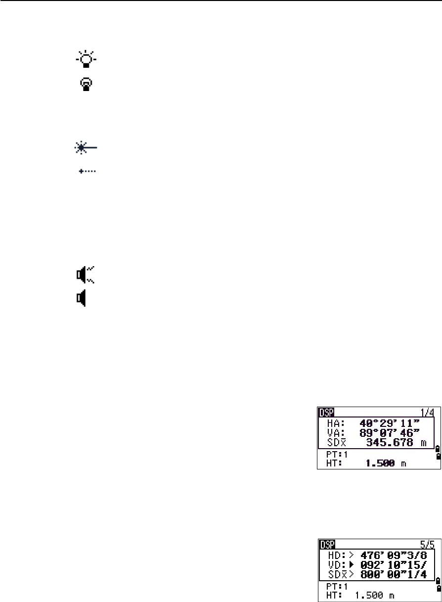
LCD backlight, laser pointer, beep sound, and contrast adjustment
Press the illumination key to open the the 4-switch window and then press:
[1] to turn the LCD backlight on/off
[2] to turn the laser pointer on /off
[3] to turn the beep sound on /off
[4] to open the contrast adjustment window.
Do the following:
•To turn on/off each function, press [ENT] when the option 1, 2, 3 or 4 is selected or
directly press the [1], [2], [3], or [4] key. Holding down the illumination key for one
second also turns on/off the LCD backlight.
•To move the cursor up and down, press [^] or [v].
•To adjust the constrast, in the contrast adjustment window, press [>] or [<] .
•To close the window, press [ESC].
Reflectorless mode
[ENT] / [4]
[ESC]
Switch setup window Contrast adjustment window
3 Getting Started
44 Spectra Precision Focus 4 Total Station User Guide
Switch 1: Adjusting the LCD backlight
Switch 2: Turning on/off the laser pointer
The icon appears while turning on the laser pointer . When the icon is on the screen,
the emitting power is Laser Class 2.
Switch 3: Turning on/off the sound
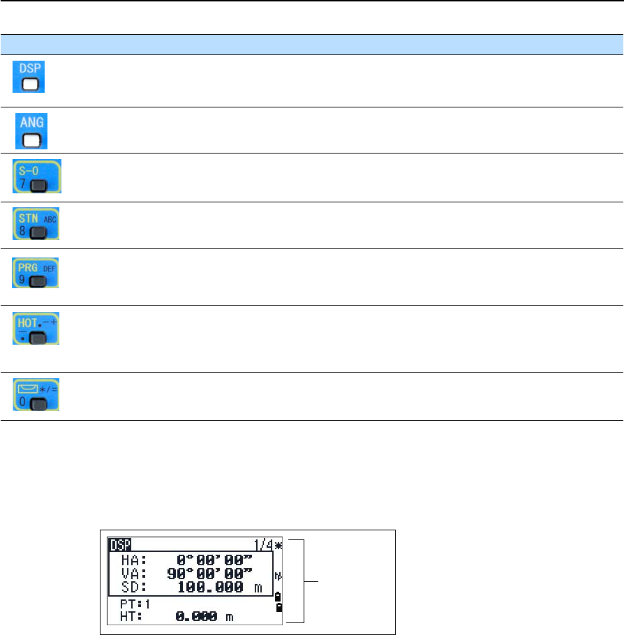
[DSP] button
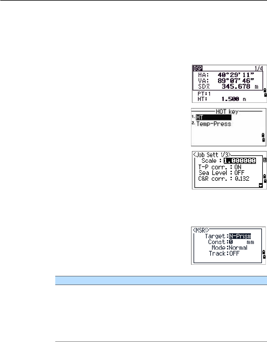
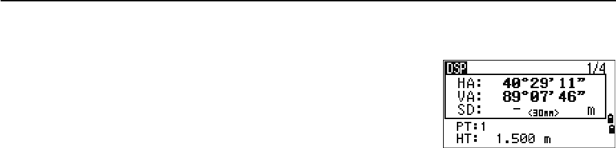
Use the [DSP] button to change the current display screen or to change display settings.
Switching between display screens
When several display screens are available:
•the DSP indicator appears at the top left of the
screen
•the screen indicator ( for example, 1/4) appears
at the top right
To move to the next available screen, press [DSP].
For example, if you are currently in the second display screen, press [DSP] to move to the
third display screen. The screen indicator changes from 2/4 to 3/4.
When the secondary distance unit is set, an additional
screen is available. It shows the HD, VD, and SD values.
See also Other settings, page 101.
The smallest unit of display for distances measured in
feet-and-inches is 1/16 inch. Smaller units are
impractical in the field.
LCD backlight is on
LCD backlight is off
Laser pointer is on
Laser pointer is off
Sound is on
Sound is off
Spectra Precision Focus 4 Total Station User Guide 45
Getting Started 3
When the actual value is greater than 99999'11"15/16, the > symbol appears. If the
actual distance is less than –9999'11''15/16, the ` (solid triangle) symbol appears. This
does not affect calculations. The precise value is used internally in all cases.
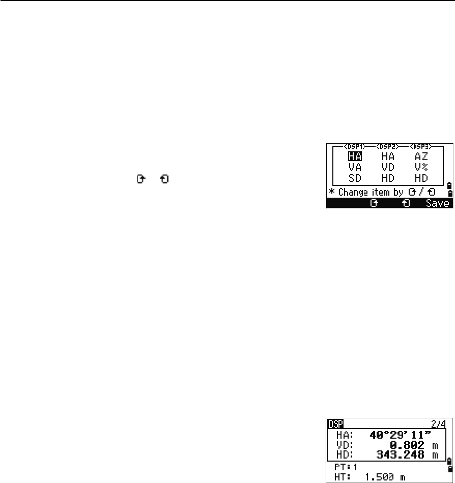
Customizing items in the Basic Measurement Screen (BMS)
To customize the items that are displayed on the DSP1, DSP2, and DSP3 screens:
1. Hold down [DSP] for one second.
2. Use the arrow buttons [^], [v], [<], and [>] to highlight
the item that you want to change:
3. Press the or softkey to scroll through the list
of items that can be displayed for this item.
The items that you can choose from are HA, AZ,
HL, VA, V%, SD, VD, HD, Z, and (none).
4. To save your changes, press the Save softkey.
Alternatively, highlight the last item for DSP3 and press [ENT]. The DSP screens
show the items you have selected.
Except for the (none) item, you cannot display the same item on more than one
line of the same screen.
The items displayed in the DSP1, DSP2, DSP3, and DSP4 screens are also used in
the corresponding Layout screens (LO2, LO3, LO4, and LO5).
You can also customize the displayed items in Layout.
Header characters
The following header characters appear in DSP screens:
•Colon (:) indicates that tilt correction is applied
to the value.
•Hash symbol (#) indicates that tilt correction is
off.
•Underscore (_) under the tilt correction
character indicates that Sea Level Correction or Scale factor is applied.
3 Getting Started
46 Spectra Precision Focus 4 Total Station User Guide
[MODE] button
The [MODE] button is on the top row of the Focus 4 keypad. Use it to change the
keyboard mode for the current screen.
Changing the input mode while entering points or codes
When the cursor is in a point (PT) or code (CD) field,
press [MODE] to change the input mode between
alphanumeric (A) and numeric (1).
The input mode indicator in the status bar changes to
show the current input mode.
When the cursor is in a height (HT) field, only numeric input mode is available.
Pressing [MODE] has no effect when the cursor is in a HT field.
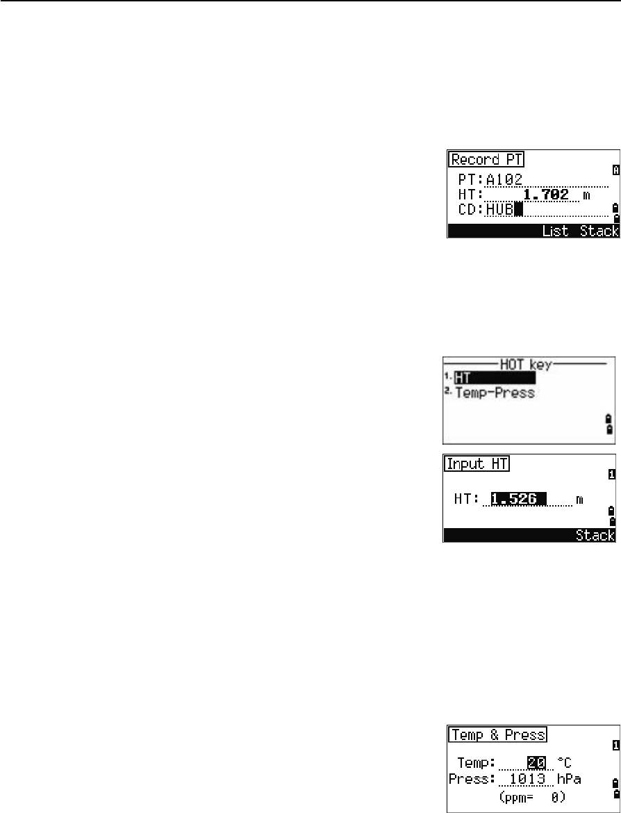
[HOT] key
The HOT key menu is available from any observation
screen. To display the HOT key menu, press [HOT].
Changing the height of the target
1. Press [HOT] to display the HOT menu.
2. Do one of the following:
–Press [1].
–Select HT.
3. Press [ENT].
4. Enter the target height or select the height from the HT stack.
Note – To display the HT stack, press the Stack softkey. The HT stack stores the last 20
HT values entered.
Setting the current temperature and pressure
1. Press [HOT] to display the HOT menu.
2. Do one of the following:
–Press [2].
–Select Temp-Press.
3. Press [ENT].
4. Enter the ambient temperature and pressure. The ppm value is updated
automatically.
Spectra Precision Focus 4 Total Station User Guide 47
Getting Started 3
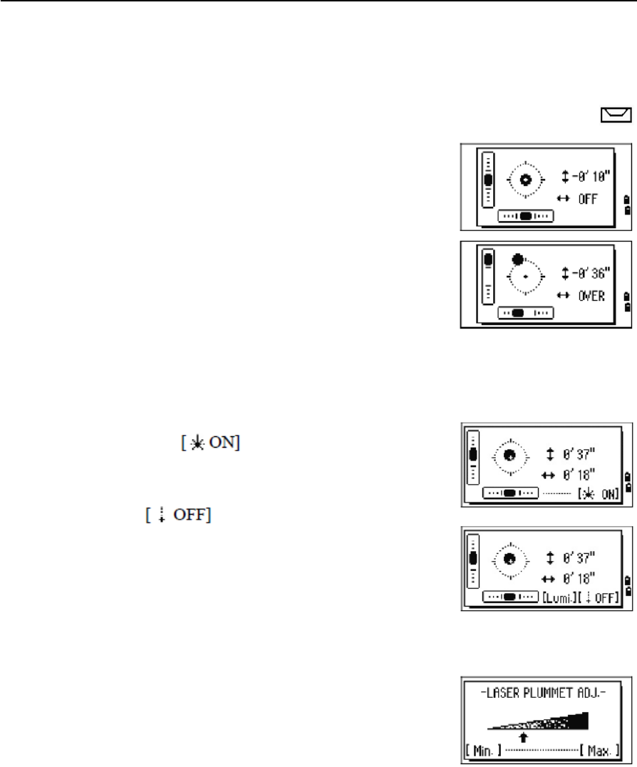
Bubble indicator
The bubble indicator appears if the instrument goes out of level while the
compensator is turned on. It also appears directly after the start up screen.
To display the bubble indicator in an observation screen at any other time, press .
The Focus 4 total station has a two-axis level
compensation. To turn the leveling compensators on or
off, press [<] or [>]. When the levelling compensators are
turned off, the text OFF appears on the screen.
If the instrument is more than ±3'30" out of level, the
text OVER appears on the screen.
To return to the observation screen, press [ESC] or [ENT].
Laser plummet (option)
Laser plummet on / off
Do one of the following:
•To turn the laser plummet switch on,
press .
•To close the bubble indicator window, press [ESC].
•To turn the laser plummet switch off, press
.
•To open the luminance adjustment window,
press [Lumi.].
•To turn the laser plummet switch off and close
the bubble indicator window, press [ESC].
Laser luminance adjustment
Laser luminance can be set to 4 levels.
•To set the luminance brighter by one level, press
[Max.] once.
•To set the luminance darker by one level, press
[Min.] once
To return to the bubble indicator window, press [ESC] or [ENT].
Note – The current setting of leveling compensators is indicated by header characters (:, #,
:, and #) after field labels (such as HA, VA, SD, and HD) in observation screens. For more
information, see Header characters, page 45.
3 Getting Started
48 Spectra Precision Focus 4 Total Station User Guide
Turning on the instrument
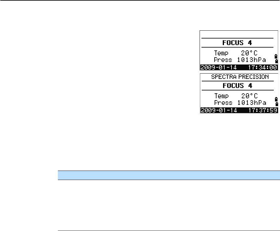
Press the [PWR] button. The start-up screen appears. It
shows the model name, current temperature, pressure,
date, and time. The display automatically changes to
the electronic level after two seconds.
If you entered your name or your company’s name in
the Owner’s detail field, the text from this field appears
on the start-up screen. To set the Owner’s detail field,
press [MENU] and then select Settings / Other.
See also Other settings, page 101.
Turning off the instrument
1. Press [PWR] and [ENT].
2. Do one of the following:
Sleep mode
To put the instrument into sleep mode, do one of the following:
•In the Press [ENT] → OFF screen, press the Sleep softkey.
•Enable the Power Save setting. See also Power saving, page 100.
The instrument wakes up if any of the following events occur:
•You press a button
•The instrument receives a remote control command
•You rotate the alidade
•You tilt the telescope
Press... To. . .
[ENT] again turn off the instrument
the Reset softkey reboot the software and re-start the instrument
access the Basic Measurement Screen (BMS) without an open
job.
the Sleep softkey put the instrument into power-saving mode
[ESC] cancel the power-off process and return to the previous screen
Spectra Precision Focus 4 Total Station User Guide 49
Getting Started 3
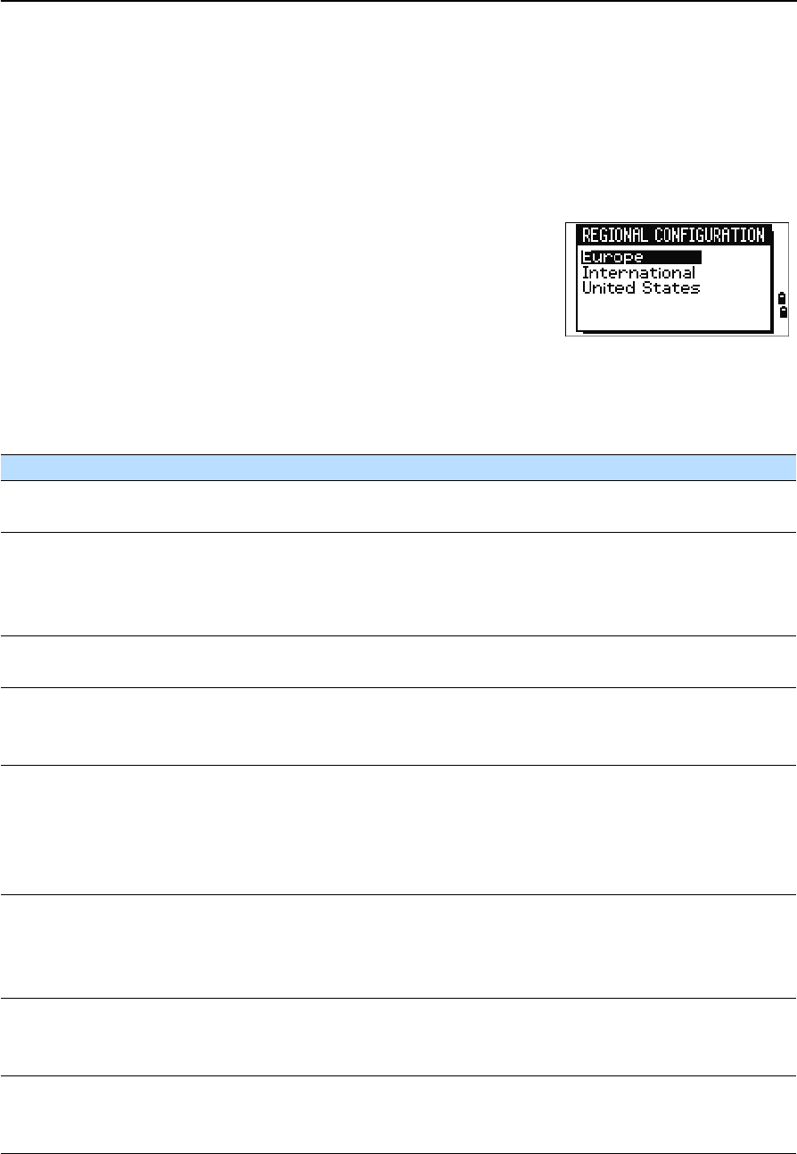
Regional configuration
To provide easier configuration for common regional settings, you can quickly
configure the Focus 4 total station to a pre-set combination of default regional settings.
The Regional Configuration screen appears only after the language configuration is
complete and the instrument has rebooted.
1. Follow the steps in Other settings, page 101 to select the required language.
Once the instrument has rebooted the Regional
Configuration screen appears.
2. Press [^] or [v] to highlight the required regional
settings and then press [ENT].
3. If you do not want to change the current settings,
press [ESC] and quit. The instrument continues to use the last settings that were
configured.
The settings affected by the Regional Configuration screen are:
Category Setting Europe International United States
Angle VA zero Zenith Zenith Zenith
Resolution 5" 5" 5"
Distance Scale 1.000000 1.000000 1.000000
T-P Corr. On On On
Sea Level Off Off Off
C&R corr. 0.132 0.132 0.132
Coordinates Order ENZ ENZ NEZ
Label ENZ ENZ NEZ
Power Save Main Unit Off Off Off
EDM Unit Off Off Off
Sleep 5 minutes 5 minutes 5 minutes
Communication Ext. Comm Nikon Nikon Nikon
Baud 4800 4800 4800
Length 8 8 8
Parity None None None
Stop bit 1 1 1
Units Angle GON DEG DEG
Distance meters meters US-ft
Temp °C °C °F
Press mm Hg mm Hg In Hg
Rec Rec Data OFF OFF OFF
CD Field OFF OFF OFF
Add Const 1000 1000 1000
Others XYZ disp Fast Fast Fast
2nd Unit None None None
CD Input <ABC> <ABC> <ABC>
3 Getting Started
50 Spectra Precision Focus 4 Total Station User Guide
The default regional configuration pre-set is “Europe” settings. See also Settings (basic
job settings), page 96.
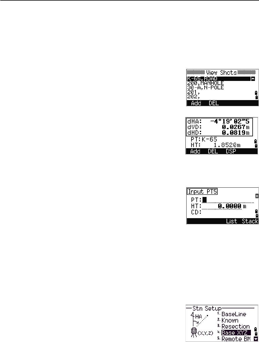
List available jobs or data
The Focus 4 total station lists available jobs or data when you do any of the following:
•view or edit data (Press [MENU] then select Data)
•open the Job Manager (Press [MENU] then select Job)
•search for points or codes
The current cursor position is shown in inverted colors
(it appears as white text on a black background).
Press [^] to move the cursor one line up, or press [v] to
move the cursor one line down.
If the Page Up icon appears, there are more pages
before the current page. Press [<] to move up one page.
If the Page Down icon appears, there are more pages after the current page. Press [>]
to move down one page.
To select an item from the list, move the cursor onto the item and press [ENT].
Entering data
You can enter the following into the Focus 4 total station:
•A point name or number, see page 50
•A code, see page 53
Entering a point name or number
You can use numeric or alphanumeric names up to 20 characters long to identify
points.
The default name for a new point is the last point name entered, with the last digit
incremented. For example, if the last point name was A100, the default name for the
next point is A101.
If the last character of the previous point name is alphabetic, the default point name is
identical to the last point name.
When the cursor is in a PT (point) field, there are several ways to specify a point, or to
enter coordinates. You can:
•Enter an existing point, see page 51
•Enter a new point, see page 51
Spectra Precision Focus 4 Total Station User Guide 51
Getting Started 3
•Press [ENT] without a point name, see page 51
•Specify a wildcard, see page 51
•Enter a point by recording an instant measurement, see page 52
•Enter a point from a point stack, see page 52
•Enter a point from the point list, see page 53
Entering an existing point
When you enter a known point name or number, the coordinates of that point are
briefly displayed. A short beep sounds before the next screen appears or the next field
is selected.
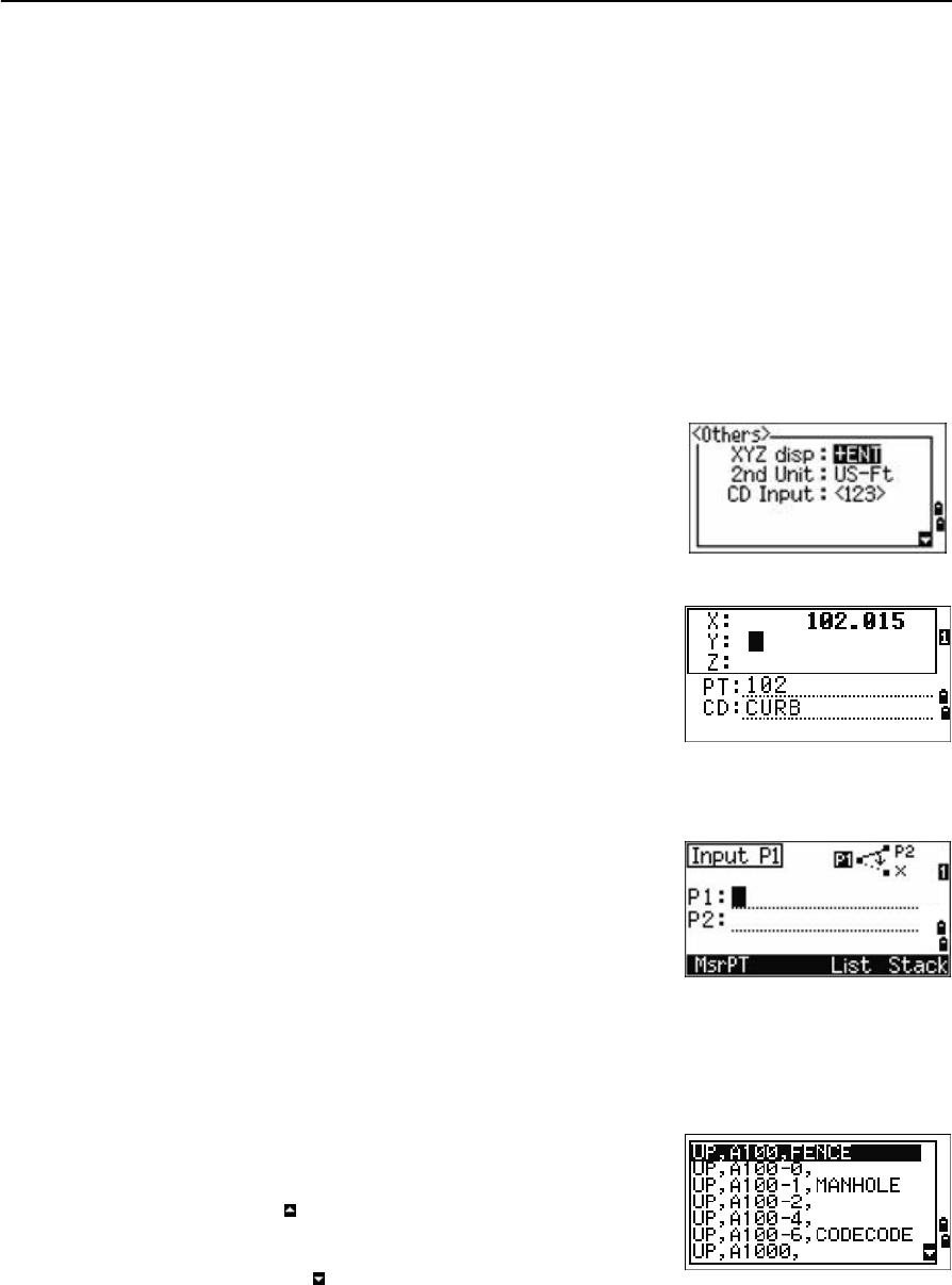
To adjust the duration of the coordinate window
display, press [MENU] then select Settings /
Others. To leave the window open until you press
[ENT], set the XYZ disp field to +ENT. See also page 101.
Entering a new point
When you enter a new point name or number, a
coordinate input screen appears. Enter the coordinates
for the point in NE, NEZ, or elevation-only (Z) format.
To store the point in the current job, press [ENT] on the
last line (the CD field).
Pressing [ENT] without a point name
To use a point without recording the coordinates, press
[ENT] in a PT field, without entering a point name.
The input coordinates are used in the calculation but
they are not saved in the database. The message This
PT will not be recorded appears.
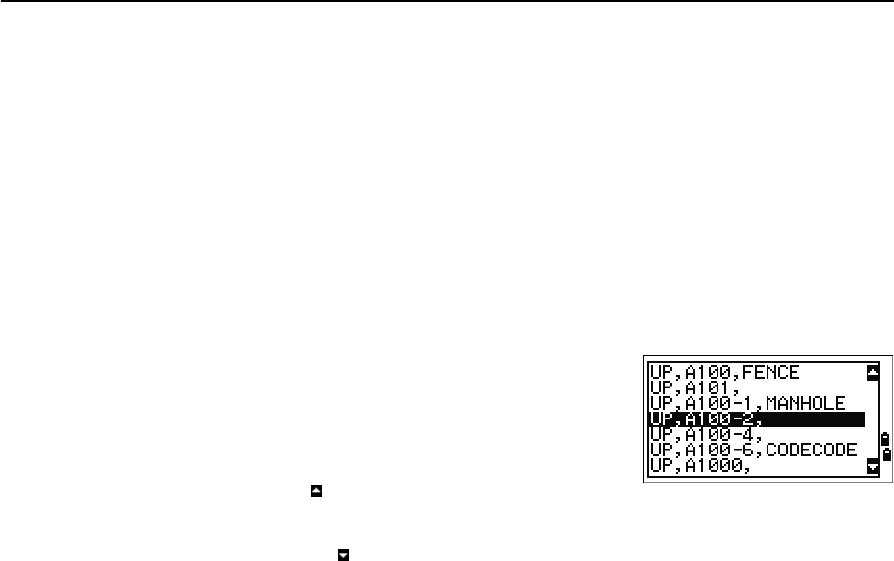
Specifying a wildcard (*)
If you include an asterisk (for example, A100*) when you enter a point or code name, a
list of points that match the entered text appears.
Use [^] or [v] to move the cursor to the point that you
want to use. Then press [ENT].
If the Page Up icon appears, you can use it to move up
one page on the list. You can also use [<].
If the Page Down icon appears, you can use it to move
down one page. You can also use [>].
When you select a point from the list, its coordinates are displayed and a beep sounds.
3 Getting Started
52 Spectra Precision Focus 4 Total Station User Guide
Entering a point by recording an instant measurement
1. Press the MsrPT softkey:
An observation screen appears.
2. To start a measurement, press [MSR1] or [MSR2].
3. To change the height of the target, select the HT
softkey.
4. When you have finished the measurement, press [ENT] to go to the point recording
screen.
5. Enter the point or code name and then press [ENT].
When you move the cursor to a field, the current or
default value appears in inverted colors. (It appears as
white text on a black background). This is the default
Replace All input mode.
To change the input mode to Overwrite and highlight
the first character, press [>]. To move the cursor to the
end of the string, press [<].
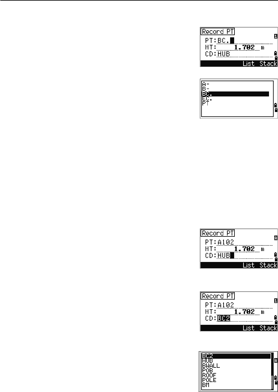
Entering a point from the point stack
The point stack is a list of the last 20 point names used,
in chronological order from last used to first used. To
enter a point from the point stack:
1. Select the Stack softkey when the cursor is in
the PT field. The stack appears.
2. Press [^] or [v] to move the cursor to the point that you want to use.
3. Press [ENT].
When you return to the point input screen, the selected
point name is entered in the PT field, incremented by
one. For example, if you selected the A101 point, A102
appears in the PT field.
Spectra Precision Focus 4 Total Station User Guide 53
Getting Started 3
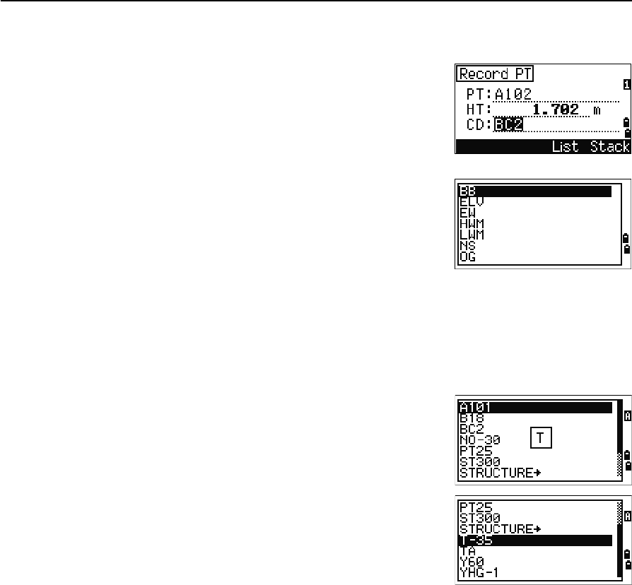
Entering a point from the point list
1. Select the List softkey when the cursor is in the
PT field. A list of existing points appears.
2. Press [^] or [v] to move the cursor to the point that
you want to use.
3. Press [ENT].
When you return to the point input screen, the selected
point name is entered in the PT field. Add numeric or
alphabetic characters if required.
Entering a code
The CD (Code) field defaults to the last code used. You can select a different code in the
input point screen.
Codenames can be numeric or alphanumeric, and up to 16 characters long.
There are several ways to enter a code:
•Enter a code directly, see page 53
•Enter a code from the code stack, see page 53
•Enter a code from the code list, see page 54
Entering a code directly
1. To change the input mode to alphanumeric or
numeric, press [MODE].
2. Use the keypad to enter the code.
Entering a code from the code stack
The code stack is a list of up to 20 recently used codes.
When you reboot the Focus 4 total station, the code
stack is cleared.
To enter a code from the code stack:
1. Select the Stack softkey when the cursor is in the
CD field. The stack appears.
2. To move the cursor to the code that you want to
use, press [^] or [v].
3. Press [ENT].
The selected code is copied to the CD field.
3 Getting Started
54 Spectra Precision Focus 4 Total Station User Guide
Entering a code from the code list
1. Select the List softkey when the cursor is in the
CD field. A list of existing codes appear.
2. Press [^] or [v] to highlight the feature code that you
want to use.
3. Press [ENT].
A layer has an arrow at the end of the code label. If you
highlight a layer in the list and then press [ENT], the
codes and layers in that layer are displayed.
When you return to the input screen, the selected code
is entered in the CD field.
Advanced feature: Searching for a code using the first character
Items are shown in alphabetic order. To find a code quickly when the code list appears,
use the first-character search. For example, to see feature codes that begin with T, use
the keypad to enter the letter T (press [1] twice).
After each button press, the input mode field displays
the selected letter. For example, if you press [1], S
appears. If you quickly press [1] again, T appears. If you
do not press the [1] button again, the letter T is selected.
Once you select a letter, the cursor moves to the feature
code beginning with that letter.
If there is no code beginning with that letter, the cursor
moves to the next available letter.
Entering values in feet and inches
If US Survey Feet (US-Ft) or International Feet (I-Ft) is selected as the distance unit,
you can enter and display distances, HIs, HTs, and coordinate values in decimal feet or
in feet and inches. See also Unit, page 99, and Other settings, page 101.
To enter values in feet and inches in an input screen, enter the elements, separated by
periods (.), in the following format:
The default denominator is 16. If the denominator is 16, you do not have to enter it,
and it is not displayed on the screen.
<Feet> [.] <Inches> [.] <Numerator> [.] <Denominator> [ENT]
(0–11) (0–15) (0–99)
Spectra Precision Focus 4 Total Station User Guide 55
Getting Started 3
For example, if you enter
[2] [.] [0] [8] [.] [5] [.] [ENT], it appears as 2'08" 5/ (2 feet, 8
and 5/16ths inches).
The following examples show how to enter various values:
The numerator and denominator that you enter are automatically converted to the
closest value from the following list: 0, 1/8, 1/4, 3/8, 1/2, 5/8, 3/4, 7/8, 1/16, 3/16, 5/16,
7/16, 9/16, 11/16, 13/16, 15/16.
If the denominator is 16, it is not shown on the screen.
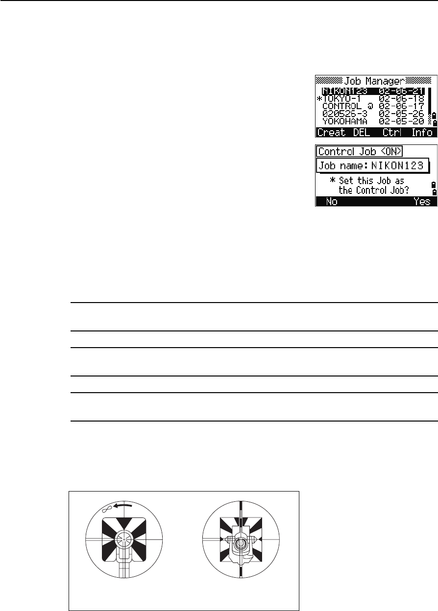
Creating or opening a job
To record data on the Focus 4 total station, you must create or open a job.
Note – Before using the Focus 4 total station for the first time, check that you are using the
required job settings.
Creating a new job
1. Press [MENU]. The MENU screen appears.
2. Press [1]. The Job Manager appears.
3. Select the Creat softkey. The Create Job screen appears.
4. Enter the job name.
5. To check the job settings, select the Sett softkey.
You cannot change the settings for a job once you
have created the job.
6. Press [ENT] in the last field of the Job Sett screen.
The new job is created.
Note – You can have a maximum of only 32 jobs.
To enter... Key in...
65' 5 3/8" [6] [5] [.] [5] [.] [3] [.] [8] [ENT]
65' [6] [5] [ENT]
65' 5" [6] [5] [.] [5] [ENT]
65' 5 3/8" [6] [5] [.] [5] [.] [6] [ENT]
5 3/8" [0] [.] [5] [.] [3] [.] [8] [ENT] or [0] [.] [5] [.] [6] [ENT]
3 Getting Started
56 Spectra Precision Focus 4 Total Station User Guide
Creating a control job
A control job, or common file, stores coordinate data that is used by several field jobs.
To create a control job in the office:
1. Press [MENU]. The MENU screen appears.
2. Press [1] or select Job. The Job Manager appears.
3. Move the cursor to the job to use as the control
job.
4. Select the Ctrl softkey.
5. Select the Yes softkey.
When you enter a point name or number, the system
searches in the current job first. If the point is not found
in the current job, the search is automatically extended
to the control job. If the point is found in the control job, the selected point is copied to
the current job as a UP record.
Measuring distances
CWARNING – Never look at the sun through the telescope. If you do, you may damage or
lose your eyesight.
CWARNING – Precautions should be taken to ensure that persons do not look directly, with
or without an optical instrument, into the beam.
CWARNING – Laser beam path should be located well above or below eye level wherever
practicable.
Sighting a prism reflector
Sight the telescope until you see cross-hairs at the center of the prism reflector.
Sighting a single prism Sighting a tiltable
single prism
Spectra Precision Focus 4 Total Station User Guide 57
Getting Started 3
Taking a distance measurement
To take a distance measurement, press [MSR1] or [MSR2] in the Basic Measurement Screen
(BMS) or in any observation screen.
While the instrument is taking a measurement, the prism constant appears in a
smaller font.
If tracking is set to ON, measurements are taken
continuously until you press [MSR1], [MSR2], or [ESC]. Each
time a measurement is taken, the distance is updated.
To change the height of target (HT), temperature, or
pressure, press [HOT]. See also [HOT] button, page 46.
Settings that relate to corrections (T-P corr, Sea Level,
C&R corr., and Map projection) are included in the job
settings and are job-specific. To change any of these
settings, you must create a new job. See also Job
settings, page 93, and Settings (basic job settings),
page 96.
Viewing and changing the measurement settings
1. Hold down [MSR1] or [MSR2] for one second.
2. To move the cursor between the fields, press [^] or
[v].
3. To change the value in the selected field, press [<]
or [>].
Field Values
Target Prism
N-Prism
Const (prism constant) –999 mm through 999 mm
Mode Precise
Normal
Track Track (continuous MSR) ON
Track (continuous MSR) OFF
3 Getting Started
58 Spectra Precision Focus 4 Total Station User Guide
Target field
•If the measurement is started with the Target
field set to Prism, there is a dash “–” in front of
the prism constant.
•If the measurement is started with the Target
field set to N-Prism, there is a right square
bracket “]” in front of the prism constant.
The symbol then continuously moves from left to right over the prism constant in
the display.
The Target setting is used by the Focus 4 total station to apply better cyclic-error
adjustment in distance measurement. The target setting efficiently eliminates
multipath reflection.
An incorrect Target setting may result in measurements outside the precision and
intervals specified for the instrument.
If a prism target is aimed in N-prism mode, the warning message Signal
High!→Try Prism Mode is displayed because of the excessive light reflection.
A measurement made immediately after changing the target setting may take longer
than usual.

CHAPTER
4
Spectra Precision Focus 4 Total Station User Guide 59
Applications 4
QHA reset and angle operations
QStation setup
QStakeout menu
QPrograms menu
QRecording measurement data
QSwitching between display
screens
This chapter describes the menu and display
screens, and Focus 4 total station applications.
Use the following keystrokes when working in
the display screens and when you use the
applications:
To switch between
display screens
Press [DSP]. See also
page 90.
To change HT Press [HOT]
To record points Press [ENT]
4 Applications
60 Spectra Precision Focus 4 Total Station User Guide
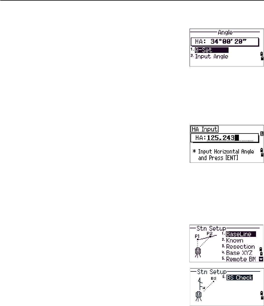
HA reset and angle operations
To access the Angle menu, press [ANG] in the Basic
Measurement Screen (BMS). To select a command from
the Angle menu, press the corresponding number key.
Alternatively, press [^] or [v] to highlight the command
and then press [ENT].
Setting the horizontal angle to 0
Press [1] or select 0-Set in the Angle menu. The display returns to the BMS.
Entering the horizontal angle
1. Press [2] or select Input in the Angle menu. The
HA Input screen appears.
2. Use the numeric keys to enter the horizontal
angle.
3. Press [ENT].
To enter 123°45'50", key in [1] [2] [3] [.] [4] [5] [5] [0].
The displayed value is rounded to the minimum angle increment.
Station setup
To access the Stn Setup menu, press [STN] in the BMS.
To select a command from the Stn Setup menu, press
the corresponding number key. Alternatively, press [^] or
[v] to highlight the command and then press [ENT].
The last function used is highlighted.
The station setup options are:
•Baseline, page 61
•Known, page 62
•Resection, page 64
•Base XYZ, page 67
•Remote BM, page 68
•BS Check, page 69
Spectra Precision Focus 4 Total Station User Guide 61
Applications 4
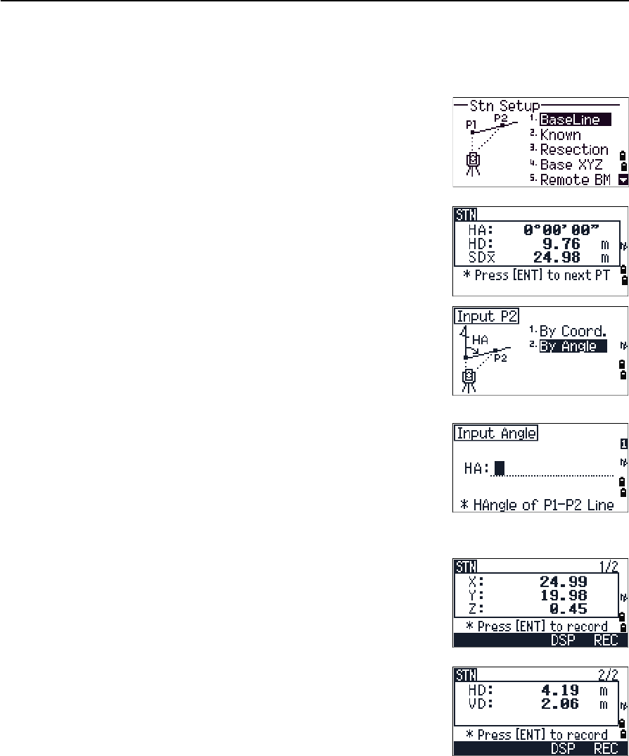
Baseline
Select this option for a two-point resection along a known line.
1. Press [1] or select BaseLine from the Stn Setup
menu.
2. Enter a known point as P1.
If you enter a new point name, a coordinate input
screen appears.
Sight P1 and press [MSR1] or [MSR2] to take a
measurement. Press [ENT].
3. Choose how you want to define a known line:
–To define the line by entering P2
coordinates, press [1] or select By Coord.
–To define the line by entering the azimuth,
press [2] or select By Angle.
a. If you select By Angle, the azimuth input
screen appears: Enter the angle value and
press [ENT].
A measurement screen appears.
b. Sight P2 and press [MSR1] or [MSR2] to take a
measurement. Press [ENT].
After the measurement to P2 is completed,
press [ENT]. The coordinates of the station are
calculated.
4. To record the station, press [ENT] or the REC
softkey.
5. To check the measurement, press the DSP
softkey. If you defined the line by entering its
azimuth, the HD and VD between P1 and P2 are
displayed.
If you defined the line by entering the P2
coordinates, the difference of HD (dHD) and VD
(dZ) between your measurement data and input
coordinate data are displayed.
4 Applications
62 Spectra Precision Focus 4 Total Station User Guide
6. Enter the station name, the height of instrument
(HI), and a feature code (CD) if required. The
station name defaults to the last recorded PT + 1.
7. Backsight (BS) defaults to the first point (P1). To
change the selected point, highlight the BS field
and then select the Change softkey.
8. To finish the setup and record the station, press [ENT] in the BS field.
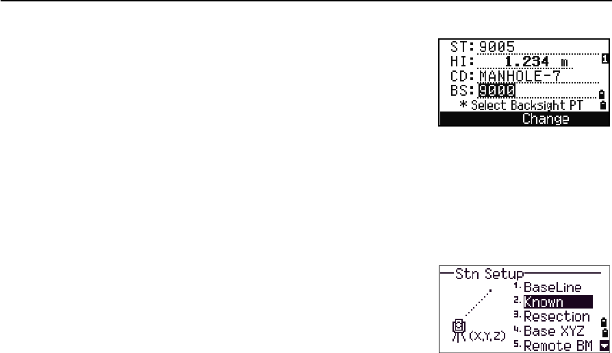
Known
Select this option to set up a station with known coordinates or azimuth.
1. Press [2] or select Known in the Stn Setup menu.
2. Enter a point name or number in the ST field.
–If the input point number or name is an
existing point, its coordinates are displayed
and the cursor moves to the HI (Height of
instrument) field.
–If the point is new, a coordinate input screen appears. Enter the
coordinates for the point. Press [ENT] after each field. When you press [ENT] in
the CD field, the new point is stored.
–If the specified point has a code, the code appears in the CD field.
3. Enter the instrument height in the HI field and then press [ENT].
4. In the Backsight screen that appears, select an input method for defining the
backsight point:
–To sight the backsight by entering coordinates, see the following section.
–To sight the backsight by entering the azimuth and angle, see page 64.
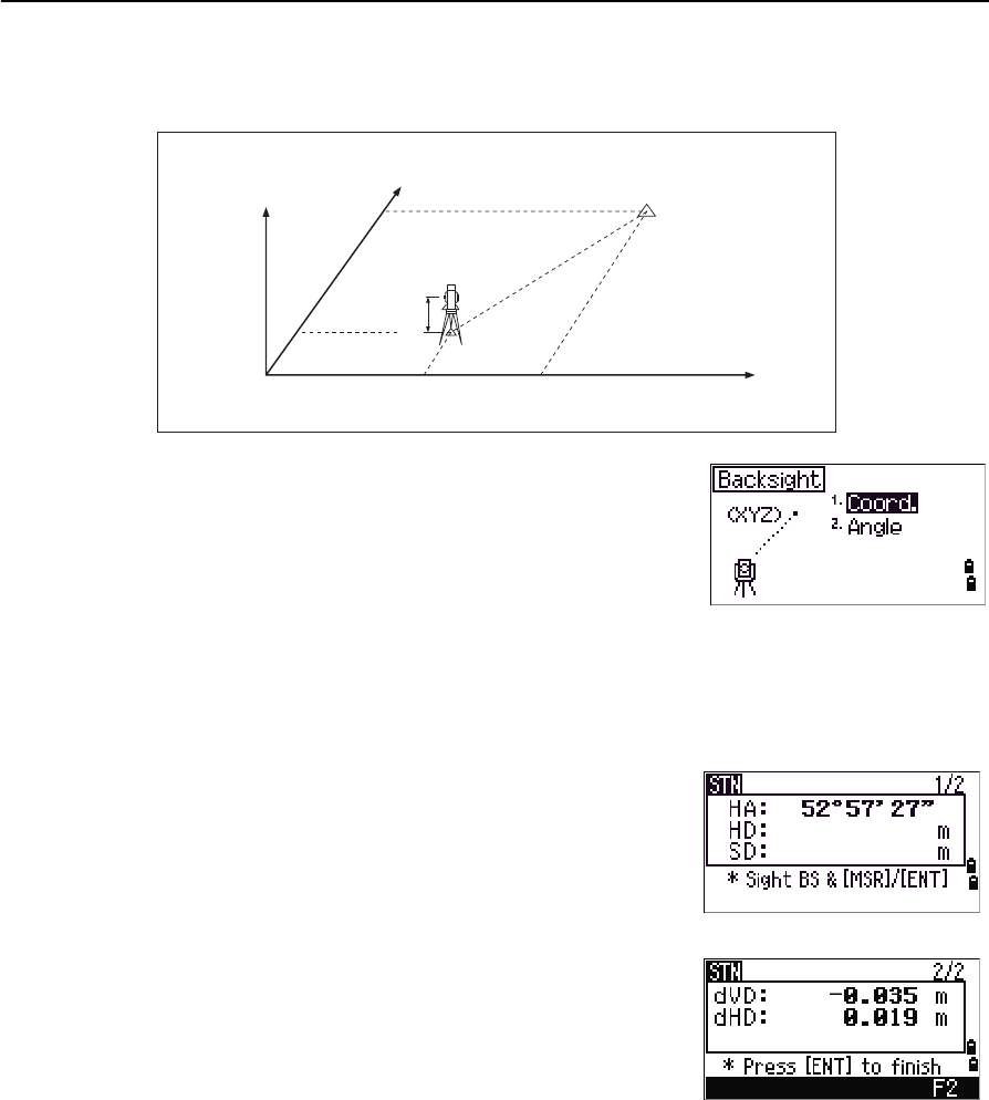
Spectra Precision Focus 4 Total Station User Guide 63
Applications 4
Sighting the backsight by entering coordinates
1. To enter coordinates for the backsight point (BS),
press [1] or select Coord from the Backsight
screen.
2. Enter the point name. If the point exists in the
job, its coordinates are shown.
3. If you intend to take a distance measurement to the BS, enter the height of
target in the HT field.
4. Sight the BS, and then press [ENT] to complete the setup.
If measuring to a known coordinate BS, press
[DSP] to display a QA screen. The QA screen shows
the dHD and dVD values, which indicate the
difference between the measured distance and
the distance calculated from the known
coordinates.
5. To record the station, press [ENT].
6. To finish the station setup after taking a distance measurement, press [ENT].
HA Azimuth calculated by
coordinates
Z
Y
X0
X
Xb
Y0 Yb
Backsight point
(Xb, Yb, Zb)
Station point
(Xi, Yi, Zi)
Instrument height
4 Applications
64 Spectra Precision Focus 4 Total Station User Guide
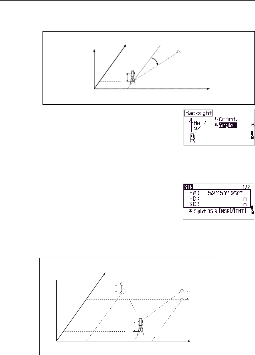
Sighting the backsight by entering the azimuth angle
1. To enter the azimuth angle to the backsight
point, press [2] or select Angle from the
Backsight screen.
2. If there is no point name for the BS, press [ENT] on
the BS field.
3. In the HA field, enter the azimuth angle to the BS point.
If you press [ENT] without entering a value in the HA field, the azimuth is
automatically set to 0°00'00".
4. Sight the BS point and press [ENT].
Resection
A resection sets up the station using angle/distance measurements to known points.
Backsight point
Azimuth
Station point
(Xi, Yi, Zi)
Instrument height
X
Y0
Y
Z
X0
X2
X1
X
Height 1
Height 2
Instrument height
Station point (Xi, Yi, Zi)
Y1 Y0 Y2 Y
Known point 1
(X1, Y1, Z1)
Known point 2
(X2, Y2, Z2)
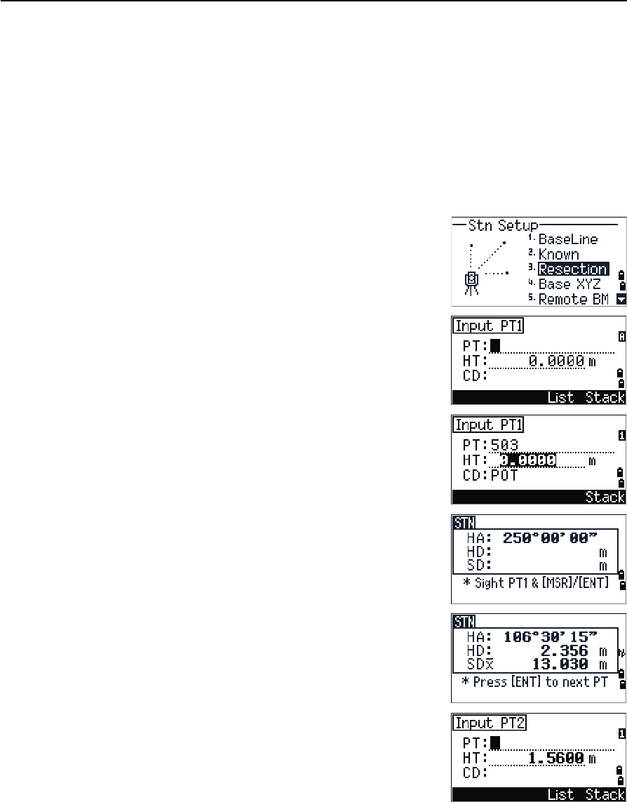
Spectra Precision Focus 4 Total Station User Guide 65
Applications 4
You can use a maximum of 10 points in a resection. Measurements can be distance and
angle, or angle only. Calculation starts automatically when enough measurements are
taken.
You can delete poor observations and recalculate if necessary. You can also select the
BS point.
BTip – If the angle between known point 1 and known point 2 (measured from the station
point) is extremely acute or extremely oblique, the resulting solution will be less reliable
geometrically. For geometric reliability, select known point locations (or station point
locations) that are widely spaced.
1. To start the resection, press [2] or select
Resection in the Stn Setup menu.
2. Enter the point name for the first observation
point (PT1).
3. Enter the target height and press [ENT].
4. Sight PT1 and press [MSR1] or [MSR2].
5. To proceed to the next point, press [ENT].
6. Enter the second point (PT2) and its height of
target.
4 Applications
66 Spectra Precision Focus 4 Total Station User Guide
7. Measure to PT2 and press [ENT].
When the instrument has enough data, it
calculates the station (STN) coordinates.
–If more than the minimum required data is
available, a standard deviation screen
appears.
–To take measurements to strengthen
geometry of the resection, press the Add
softkey. For information about the View
softkey, see Advanced feature: Viewing and deleting a measurement in
resection, page 67.
8. When the results are satisfactory, record the
station. To do this, press [ENT] or the REC softkey.
9. Enter the height of instrument, if required. Press
[ENT]. The ST field defaults to the last recorded
PT + 1.
10. To change the station name, move to the ST field
and edit or replace the text.
BTip – If you have set Split ST to Yes, the ST field defaults
to the last recorded ST value + 1.
BS defaults to the first observed point.
11. To change the BS, press the Change softkey.
12. Select the BS point that you want to use and
press [ENT].
13. To finish the resection setup, move the cursor to
the BS field and press [ENT].
Spectra Precision Focus 4 Total Station User Guide 67
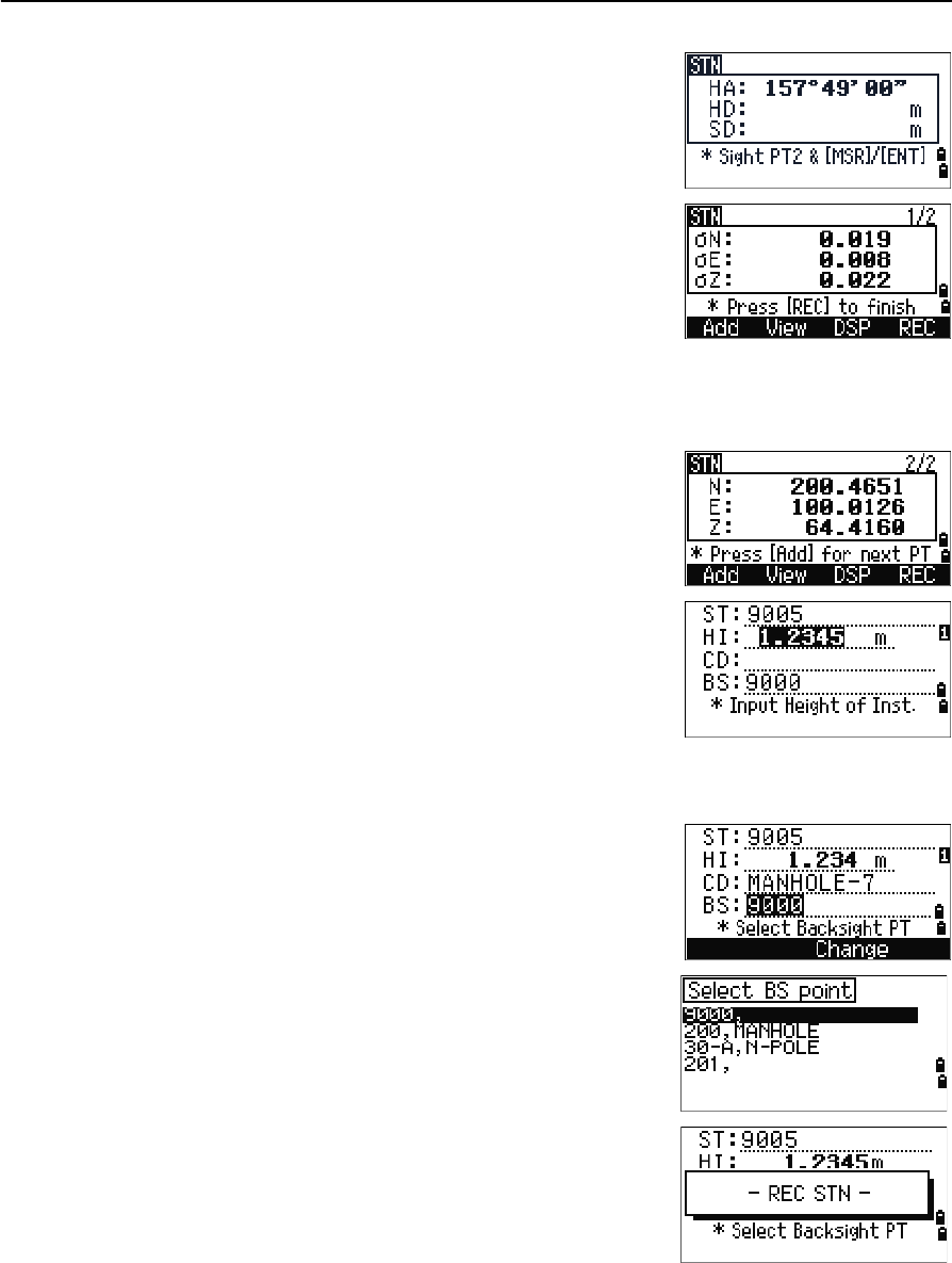
Applications 4
BTip – The minimum data required for a resection is either three angle shots, or one angle
shot and one distance shot. If you use a distance shot, the distance between the target
points must be greater than the measured distance. Stn-Z is calculated from
distance-measured data. If no distances are measured, then Stn-Z is calculated using
angle-only measurements to points with 3D coordinates.
Advanced feature: Viewing and deleting a measurement in resection
To check the measurements to each known point, press
the View softkey on the calculated STN (sigma or
coordinate) screen.
To delete a measurement (because of large sigma values, for example), highlight the
measurement data or display the detail screen for the measurement. Then press the
DEL softkey. The STN coordinates are automatically recalculated.
To continue resection observations, press the Add
softkey. The input screen for the next PT appears.
Base XYZ
Select this option to change the instrument XYZ values.
Base XYZ does not store an ST record in the job, so the BS Check cannot check the
backsight if you enter a station using the Base XYZ option.
You can use this function without an open job.
1. Press [3] or select Base XYZ from the Stn Setup
menu.
The current instrument XYZ values are shown as
the default.
2. Enter the new instrument XYZ values and then
press [ENT].
3. Do one of the following:
dHA Distributed HA errors in each direction
dVD VD errors between measured distance and
calculated distance
dHD HD errors between measured distance and
calculated distance
4 Applications
68 Spectra Precision Focus 4 Total Station User Guide
–To reset the horizontal angle, enter a value in the HA field and then press
[ENT].
–If you do not need to reset the horizontal angle, leave the HA field blank
and then press [ENT].
The Stn Setup menu appears.
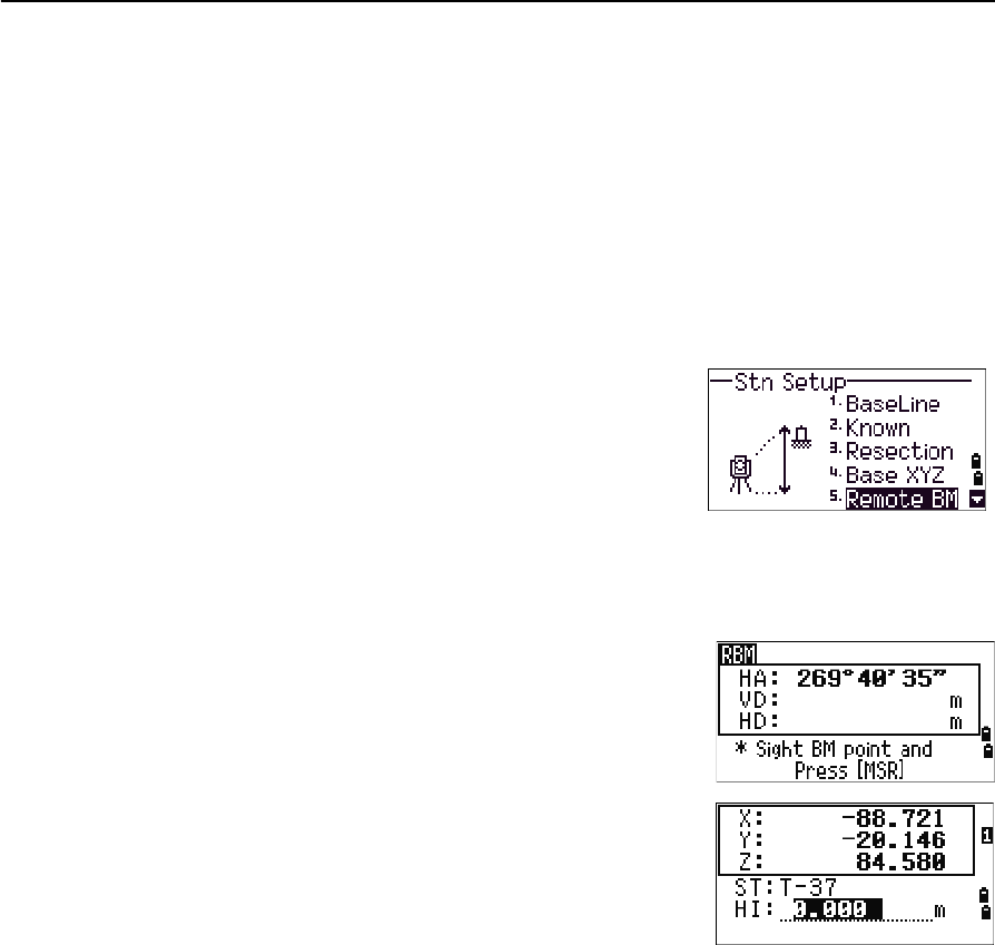
Remote BM
Select this option to determine the station elevation.
1. Press [4] or select Remote BM from the Stn
Setup menu.
2. Enter the BM point and press [ENT]. The point
appears briefly. The cursor then moves to the HT field.
3. Enter the HT and then press [ENT].
4. Sight the Bench Mark point and then press [MSR1]
or [MSR2].
The updated station coordinates are displayed.
You can change the HI in this screen.
5. To record the updated STN, press [ENT].
When the HI setting is changed, the Z coordinate is
updated before the station is recorded.
You must complete a station setup before you use the Remote Benchmark function.
Spectra Precision Focus 4 Total Station User Guide 69
Applications 4
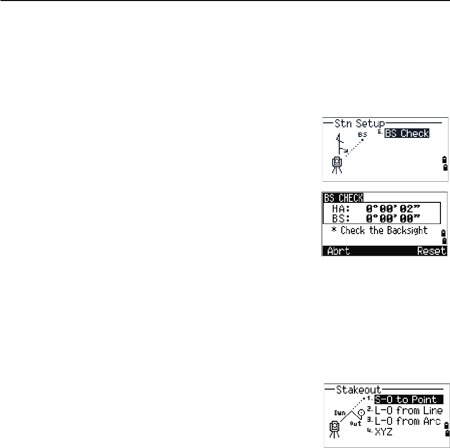
BS Check
Select these options to check and reset the backsight direction.
Note – Complete a station setup before using the BS check function.
This function always refers to the backsight point from the last station (ST) record
stored in the current open job.
1. Press [5] or select BS Check in the Stn Setup
menu.
The HA field refers to the current HA reading,
and the BS field refers to the BS in the last station
setup. Enter station coordinates for observations
without recording data.
2. Do one of the following:
–To reset the horizontal angle to the HA set in the last station setup, sight
the BS and then select the Reset softkey or press [ENT].
–To cancel the process and return to the BMS, select the Abrt softkey or
press [ESC].
Stakeout menu
To access the Layout menu, press [L-O] in the BMS.
To select a command from the Layout menu, press the
corresponding number key. Alternatively, press [^] or [v]
to highlight the command and then press [ENT].
The last function used is highlighted.
There are four layout options:
•S-O to Point, page 70
•L-O from Line, page 71
•L-O from Arc, page 72
•XYZ, page 73
4 Applications
70 Spectra Precision Focus 4 Total Station User Guide
S-O to Point
Use this method to lay out a point based on the down, out, and dZ location to a
specified line.
1. Press [1] or select
S-O to Point from the Layout menu.
2. Enter the first point (P1) along the line.
Alternatively, select the MSR softkey to measure a
point.
If you press [ENT] without entering a PT name, you
can enter temporary coordinates. Temporary
coordinates are not recorded in the job.
3. Enter the second point (P2) along the line.
4. Enter offsets to the line.
To enter the value 0.0000, press [ENT] in a blank field.
5. Rotate the instrument until the dHA is close to 0°00'00".
6. Sight the target, and then press [MSR1] or [MSR2].
When a distance measurement is taken, the
difference between the measured point and the
design point appears.
7. To record the point as an SO record, press [ENT].
Note – Press [DSP] to switch between display screens. See
also page 90.
Sta Distance from P1 along the line
O/S Distance perpendicular to the line
(+) Right side of the P1−P2 line
(-) Left side of the P1−P2 line
dZ Difference in height from the line
Spectra Precision Focus 4 Total Station User Guide 71
Applications 4
The following figure shows the terminology used to guide you to the required point.
L-O from Line
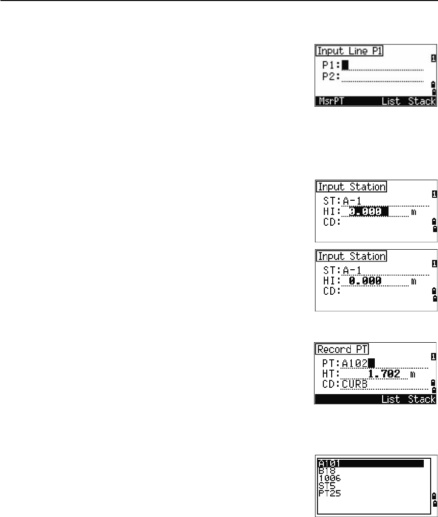
Select this option to measure distance and offset values along a specified line.
1. Press [2] or select L-O from Line from the
Layout menu.
2. Enter the first point for the reference line.
Alternatively, select the MSR softkey to measure a
point.
If you press [ESC] in the Record PT screen, the measured point is used but not
recorded in the job.
3. Enter the second point for the reference line.
4. Enter an asterisk ( for example, A*) in the PT field to perform a wildcard search.
A list of matching points appears. Highlight a point in the list and then press
[ENT].
Fill
Out
Cut
L
R
In In Out
R
L
Fill
Cut
4 Applications
72 Spectra Precision Focus 4 Total Station User Guide
The following figure shows how to determine or input a location relative to a
line used for Layout.
5. Sight the prism or reflective sheet and press [MSR1] or [MSR2].
Note – Press [DSP] to switch between display screens. See also page 90.
L-O from Arc
Select this option to measure distance and offset values on the arc-curve.
1. Press [3] or select L-O from Arc from the
Layout menu.
2. Enter the start of the curve point (P1) and the
azimuth of its tangent line (HA1).
Alternatively, to enter P1 by direct measurement,
select the MSR softkey.
3. Choose a method to define the curve.
P2 can be any point on the tangent line that is to
exit the curve.
4. In the radius (Rad) field, enter a positive value for
a clockwise curve. Enter a negative value for a
counter-clockwise curve.
Dwn Horizontal distance from P1 to the
measured point along the P1-P2 line 6.
Out Horizontal offset from the P1-P2 line to
the measured point
dZ Vertical offset from the P1-P2 line to
the measured point
Plain view Side view
PT1
PT2
Dwn Out
Prism
Prism PT2
Dwn
PT1
dZ