NIKON TRIMBLE NT0001 Bluetooth module User Manual Nivo manual 3
NIKON-TRIMBLE CO., LTD. Bluetooth module Nivo manual 3
Contents
Host 2 user manual 3 of 3

CHAPTER
5
Total Station Nivo Series Instruction Manual 91
Menu Key 5
In this chapter:
QIntroduction
QJob Manager
QCogo
QSettings
QData
QCommunication
Q1sec-Keys
QCalibration
QTime
5 Menu Key
92 Total Station Nivo Series Instruction Manual
Introduction
Use the MENU screen to access important functions
and settings.
To display the MENU screen, press the [MENU] key.
Job Manager
Use the job manager to open, create, delete, and
manage jobs. To open the Job Manager, press [1] or
select Job on the MENU screen.
If there are jobs stored on the instrument, the job list
appears, showing all the stored jobs. The newest job
appears at the top of the list.
If there are no jobs stored, the Create Job screen appears. See Creating a new job,
page 93.
Opening an existing job
The job list shows all the jobs stored on the instrument,
in descending date order.
The following symbols may be used to provide extra
information about jobs:
Press [^] or [v] to move up or down the job list. Press [ENT] to open the highlighted job.
When you open a job, all job settings are automatically changed to match those used
in the open job.
Symbol Meaning
* Current job.
@ Control job.
! Some of the job settings are different from the current job.
? Job was created in an older DB. Older files cannot be opened in version 1.10 or
later of the software.
Total Station Nivo Series Instruction Manual 93
Menu Key 5
Creating a new job
1. Press the Creat softkey in the job list.
2. Enter a job name of up to eight characters. Press
[ENT].
3. Do one of the following:
–To check the job settings, press the Sett
softkey.
–To create a new job using the current job
settings, press [ENT] or the OK softkey.
Job settings
The following settings are set when a job is created, and cannot be changed. This
ensures that the data in a job is correctly stored in the database, and that all necessary
corrections are applied when you store each record.
Scale Factor 0.999600 to 1.000400
T-P correction ON/OFF
Sea Level ON/OFF
C&R correction OFF/0.132/0.200
Angle unit DEG/GON/MIL
Distance unit Metre/US-Ft/I-Ft
Temp unit °C/°F
Press unit hPa/mmHg/inHg
If you select US-Ft or I-Ft, an additional settings screen appears. Use this
screen to specify whether to display values in Decimal-Ft or Ft-Inch.
VA zero Zenith/Horizon/Compass
AZ zero North/South
Order NEZ/ENZ
HA Azimuth/0 to BS
5 Menu Key
94 Total Station Nivo Series Instruction Manual
To move between fields, press [^] or [v]. Alternatively, to move to the next field, press
[ENT].
To change the setting in the selected field, press [<] or [>].
To confirm the job settings and create the job, press [ENT] in the last field (HA).
These settings are separate from other temporary settings.
Deleting a job
BTip – There is no undelete function in the Job Manager. Before you press [ENT] or select DEL,
make sure that the selected job is the one that you want to delete.
1. In the job list, highlight the job that you want to
delete.
2. Press the DEL softkey. A confirmation screen
appears.
3. Do one of the following:
–To delete the selected job, press [ENT] or the
DEL softkey.
–To cancel the deletion and return to the previous screen, press [ESC] or the
Abrt softkey.
After you delete a job, the display returns to the
job list.
Setting the control job
If you search for a point when a control job is specified, and the system cannot find
the point in the current job, the control job is also searched. If the point is found in the
control job, it is copied to the current job as a UP record.
A control job has the same format as a standard job. You can open and modify it like
any other job, and you can use it to record any measured data.
To set the control job:
1. Highlight the job that you want to use.
2. Press the Ctrl softkey.
Total Station Nivo Series Instruction Manual 95
Menu Key 5
A confirmation screen appears.
3. Do one of the following:
–To set the selected job as the control job,
press [ENT] or the Yes softkey.
–To cancel the process, press [ESC] or the No
softkey.
Displaying job Information
To display job information, highlight the job name and
then press the Info softkey.
The Information screen shows the number of records in
the job, the free space, and the date when the job was
created. Free space indicates how many points can be
stored in the job.
To return to the job list, press any key.
If a control job is already assigned, the newly assigned control job replaces it
as the control job.
To clear the control job selected, highlight the current control job in the job list
and press the Ctrl softkey. Then press [ENT] or the Yes softkey to confirm.
5 Menu Key
96 Total Station Nivo Series Instruction Manual
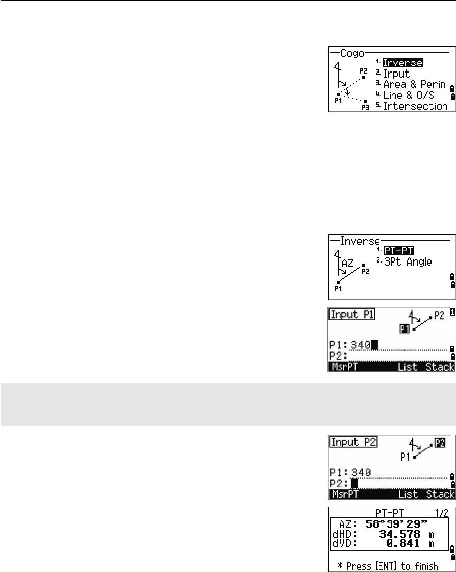
Cogo
Use the Cogo menu to perform coordinate geometry
(COGO) calculations. You can access this menu at any
time from any observation or PT input screen.
To open the Cogo menu, press [2] or select Cogo on the
MENU screen.
Calculating angle and distance between two coordinates
To open the Inverse menu, press [1] or select Inverse in the Cogo menu.
PT-PT inverse
PT-PT calculates the distance and the angle between two input points.
To calculate a PT-PT inverse:
1. Press [1] or select PT-PT in the Inverse menu.
2. Enter the first point number or name. Press [ENT].
3. Type the second point number/name and press
[ENT]. The MSR softkey allows you to shoot the
point on the spot to use it in the calculation.
The azimuth, horizontal distance, and vertical
distance from the first point to the second point
are displayed.
If you press [ENT] without entering a point name, a coordinate input screen appears, and you can enter
coordinates. These coordinates are not stored to the database. If you want to store the point, specify a new
point name.
Total Station Nivo Series Instruction Manual 97
Menu Key 5
4. Do one of the following:
–To return to the PT input screen, press [ESC].
–To return to the COGO menu, press [ENT].
–To change the contents of the result screen,
press [DSP].
3Pt angle
The 3Pt Angle function calculates the angle between
two lines defined by three points.
To calculate a 3Pt angle:
1. Press [2] or select 3Pt Angle in the Inverse
menu.
P1 is the base point. Two lines are to be defined
by P2 and P3, both from P1.
2. Enter the point name, or use the MSR softkey to
take a measurement to the point.
3. Enter the second point (P2) to define the
baseline (P1-P2). The angle (dHA) is measured
from the baseline.
4. Enter the third point (P3) to define the second
line (P1-P3).
Gd Grade (HD/VD)
V% 100/Gd
rSD Slope distance PT1 to PT2
When you press the MSR softkey, a temporary measuring screen appears. Sight the target and press [MSR1] or
[MSR2] to take a measurement.
After the measurement, a recording point screen appears. To store the
measured point, enter the PT, HT, and CD values and press [ENT]. To use the
point without recording it, press [ESC].
5 Menu Key
98 Total Station Nivo Series Instruction Manual
When you have entered three points, the
instrument calculates the angle and distances.
5. Do one of the following:
–To return to the Inverse menu, press [ENT].
–To return to the Input BasePt screen, press
[ESC].
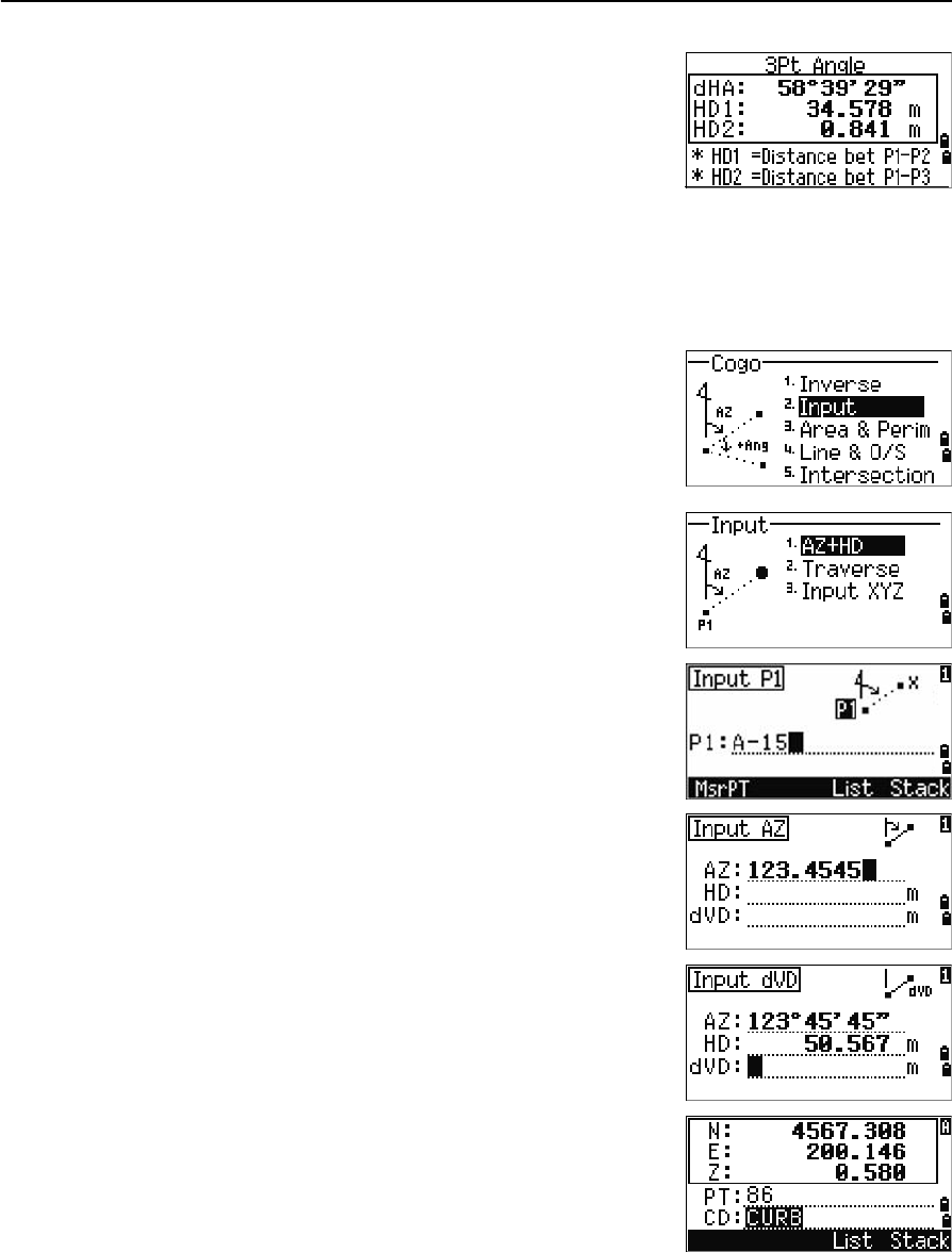
Calculating and manually inputting coordinates
To enter the Input menu, press [2] or select Input in
the Cogo menu. There are three functions in this menu
for recording new coordinate points.
Azimuth+HD input
To calculate a coordinate by an angle and distance
input from the base point (P1), press [1] or select
AZ+HD in the Input menu.
Enter the base point (P1). Type the point name and
press [ENT].
Enter the azimuth, horizontal distance, and vertical
distance. Then press [ENT].
To enter 123°45'45", type 123.4545 and press [ENT].
If you do not enter a value in the dVD field, the value
0.000 is used.
A recording point screen with the calculated
coordinates appears. PT defaults to the last recorded
PT + 1.
Press [ENT] to store the point.
Total Station Nivo Series Instruction Manual 99
Menu Key 5
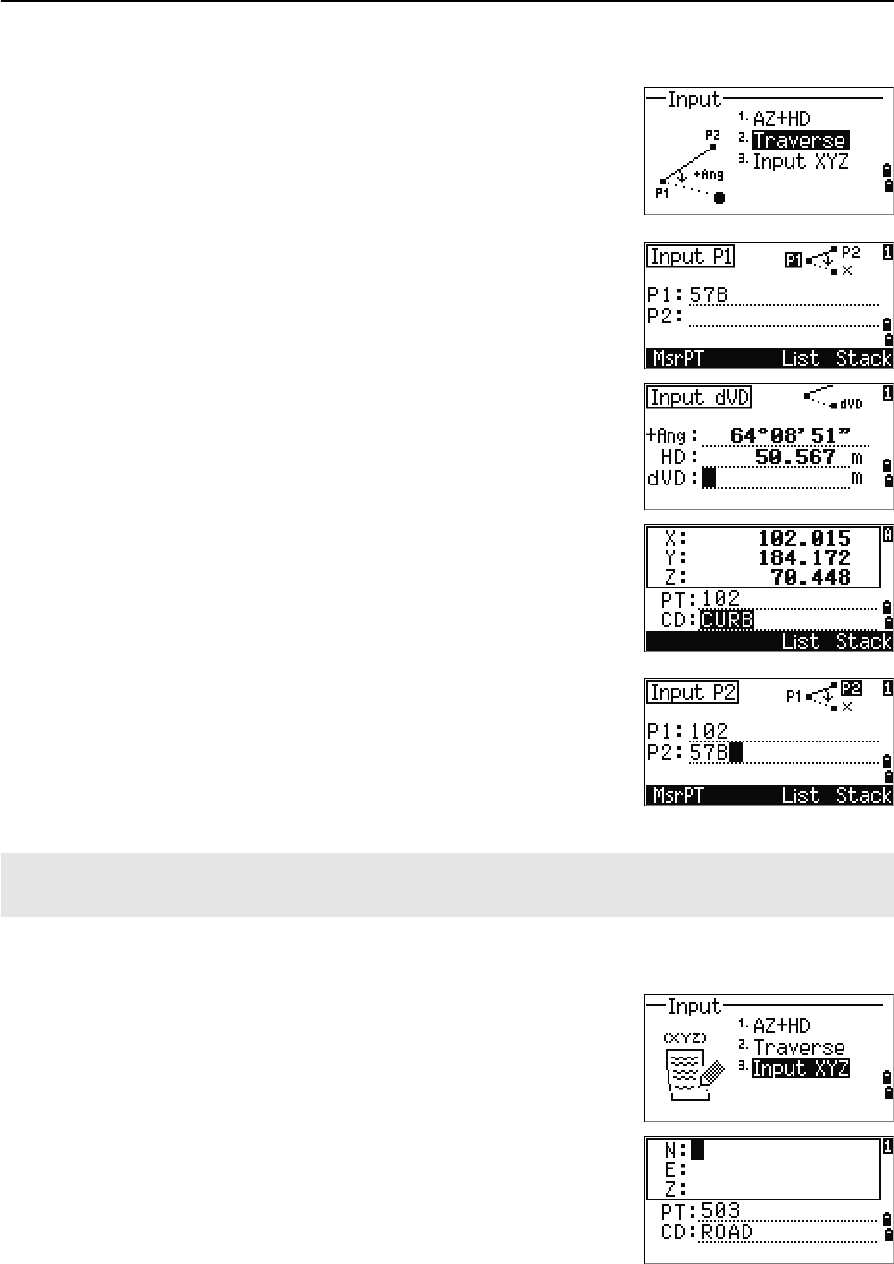
Traverse
To open the Traverse (2Pt Angle) function, press [2] or
select Traverse in the Input menu.
Traverse function calculates a new point based on the
two defined points and angle, horizontal and vertical
distances from the line defined by those two points.
To enter P1 and P2, enter point names or take
measurements to targets.
Enter the plus-minus angle, horizontal distance, and
vertical distance from the baseline defined by P1-P2.
If you do not enter a value in the dVD field, the value
0.000 is used.
When you press [ENT] in the dVD field, a new point is
calculated. The PT name defaults to the last recorded
PT + 1.
To record the new point and return to the point input
screen, press [ENT].
P1 (base PT) defaults to the previously recorded PT. P2
defaults to the previous P1.
Entering coordinates
To manually enter the XYZ coordinates, press [3] or
select Input XYZ in the Input menu.
The PT name defaults to the last recorded PT + 1.
Enter the coordinates using the numeric keys. To move
to the next field, press [ENT] or [v] in a field
To continuously calculate a new point, enter +Ang, HD, and dVD from the previous bearing line. This is a
convenient way to enter Traverse points.

5 Menu Key
100 Total Station Nivo Series Instruction Manual
To store the point as an MP record and return to the
point input screen, press [ENT] in the Z field. The default
PT is incremented to the next value.
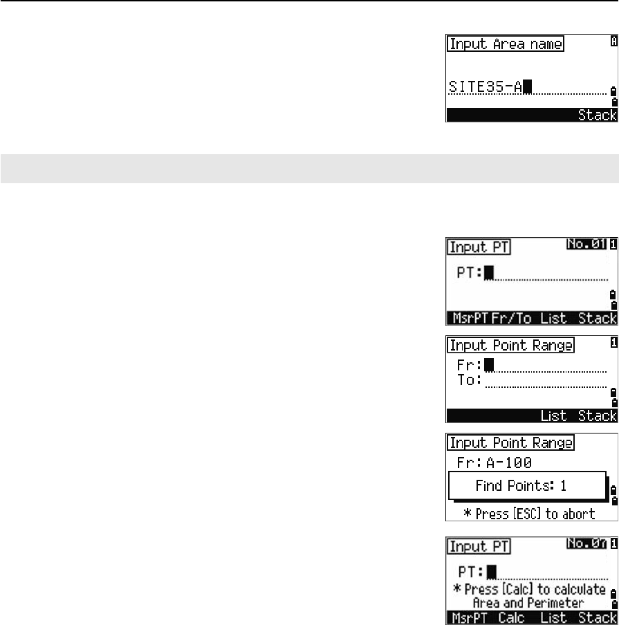
Calculating area and perimeter
To calculate an area or perimeter, press [3] or select
Area & Perim in the Cogo menu.
To take a measurement, enter the first point and press
[ENT], or press the MSR softkey.
In the upper right corner of the screen, a counter
indicates how many points you have entered.
To input point numbers consecutively, use the Fr/To
softkey. For more information, see Advanced feature:
Entering a range of points, page 101.
If you enter a new point name, you can enter new
coordinates and record the point. If you do not want to
record the point, press [ENT] without entering a value in
the PT field. An XY coordinate input screen appears.
Continue to enter points until you have defined all the
points in the lot. Then, press [v] to calculate the area and
perimeter.
Press [ENT] to store the calculated values as a a comment
record, or press [ESC] to return to the Cogo menu.
You can record NE, NEZ, or Z-only data to the database.
The first and last points that you enter are joined to close the area.
You must enter the points in the order in which they define the lot.
You can enter up to 99 points.
Total Station Nivo Series Instruction Manual 101
Menu Key 5
If you chose to store the area, enter a name to identify
the area and then press [ENT].
Advanced feature: Entering a range of points
To quickly enter a sequential range of points, use the
range input function. To access this function, press the
Fr/To softkey in the No. 01 or No. 02 input screens.
Enter the start point name in the Fr field and the end
point name in the To field. You can include letters and
hyphens in the point names, but the last character must
be numeric.
Press [ENT] in To field to start searching for matching
points. The counter shows the number of matching
points found.
When the search is complete, you are returned to the
Input PT screen.
Press the Calc softkey to calculate the area and
perimeter, or enter point names in the PT field.
Press [ESC] to return to the Input PT screen with the
preceding point name.
When you download data in Nikon RAW format, area (AR) records are output as comment (CO) records.
5 Menu Key
102 Total Station Nivo Series Instruction Manual
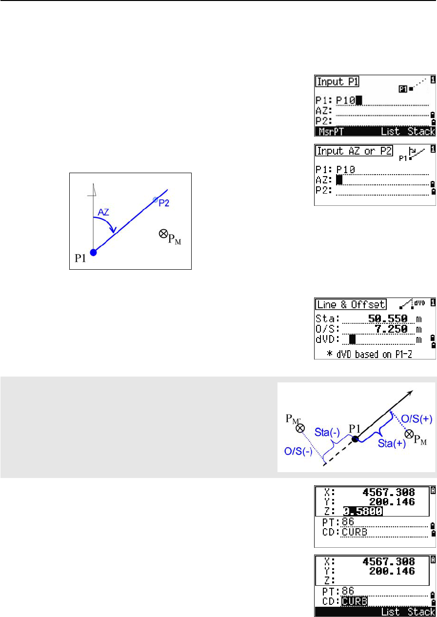
Calculating coordinates from line and offset
To enter the Line & offset function, press [4] or select Line & O/S in the Cogo
menu.
Enter the base point (P1).
Specify the azimuth bearing. To do this, enter a value
in the AZ or P2 field. P2 is a second point on the line.
Enter the horizontal distance along the baseline (Sta),
the horizontal distance perpendicular to the line (O/S),
and the vertical distance (dVD).
To calculate the coordinates of the point (PM), press
[ENT] in the dVD field. You can change the Z coordinate
here.
To record the point, press [ENT] in the CD field.
A negative value in the Sta field means the opposite direction along
the defined bearing line.
A negative value in the O/S field is for the left-hand side of the bearing
line.
Total Station Nivo Series Instruction Manual 103
Menu Key 5
The coordinates are stored as a CC record. Line
definition information and Sta, O/S, and dVD values
are stored in comment (CO) records.
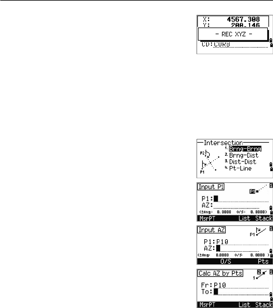
Calculating coordinates using intersection functions
To enter the Intersection menu, press [3] or select Intersection in the Cogo menu.
There are four functions in this menu for calculating coordinates.
Calculating a bearing-bearing intersection
A bearing-bearing intersection is the intersection point of two lines.
1. To calculate a bearing-bearing intersection,
press [1] or select Brng-Brng in the
Intersection menu.
2. Enter the first point name and press [ENT].
Alternatively, to measure directly to the point,
press the MSR softkey.
3. Define the first line by azimuth.
4. To define the line by two points, press the Pts
softkey. The Fr field defaults to the P1 point, but
you can change the selected point. In the To
field, enter or measure to the second point.
For more information about the O/S softkey, see
Advanced feature: Entering angle and distance
offsets, page 107.
5. Do one of the following:
–To return to the previous screen, press [ESC].
The calculated value appears in the AZ field.
–To go to the next screen, press [ENT].
5 Menu Key
104 Total Station Nivo Series Instruction Manual
6. Define the second line by two points or by P2
and AZ.
7. To calculate the coordinates of the intersection
point, press [ENT] in the AZ field.
The calculated coordinates are displayed. You
can input a Z coordinate if necessary.
8. Enter a value in the PT field and in the CD field.
9. To record the point, press [ENT].
Sample records
CO,Int BB P1:P10 AZ:330.54175-90.00000
CO, P2:408 AZ:100.0000+0.0000
CC,A123,,4567.3080,200.1467,-1.2056,POT
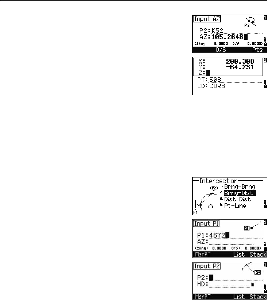
Calculating a bearing-distance intersection
1. Press [2] or select Brng-Dist in the
Intersection menu.
Brng-Dist calculates the intersection point
formed by one line and one distance (radius).
2. Enter a point on the line.
The line can be defined by two points or by a
point and an azimuth.
3. Enter the second point (P2) as the center of the
circle.
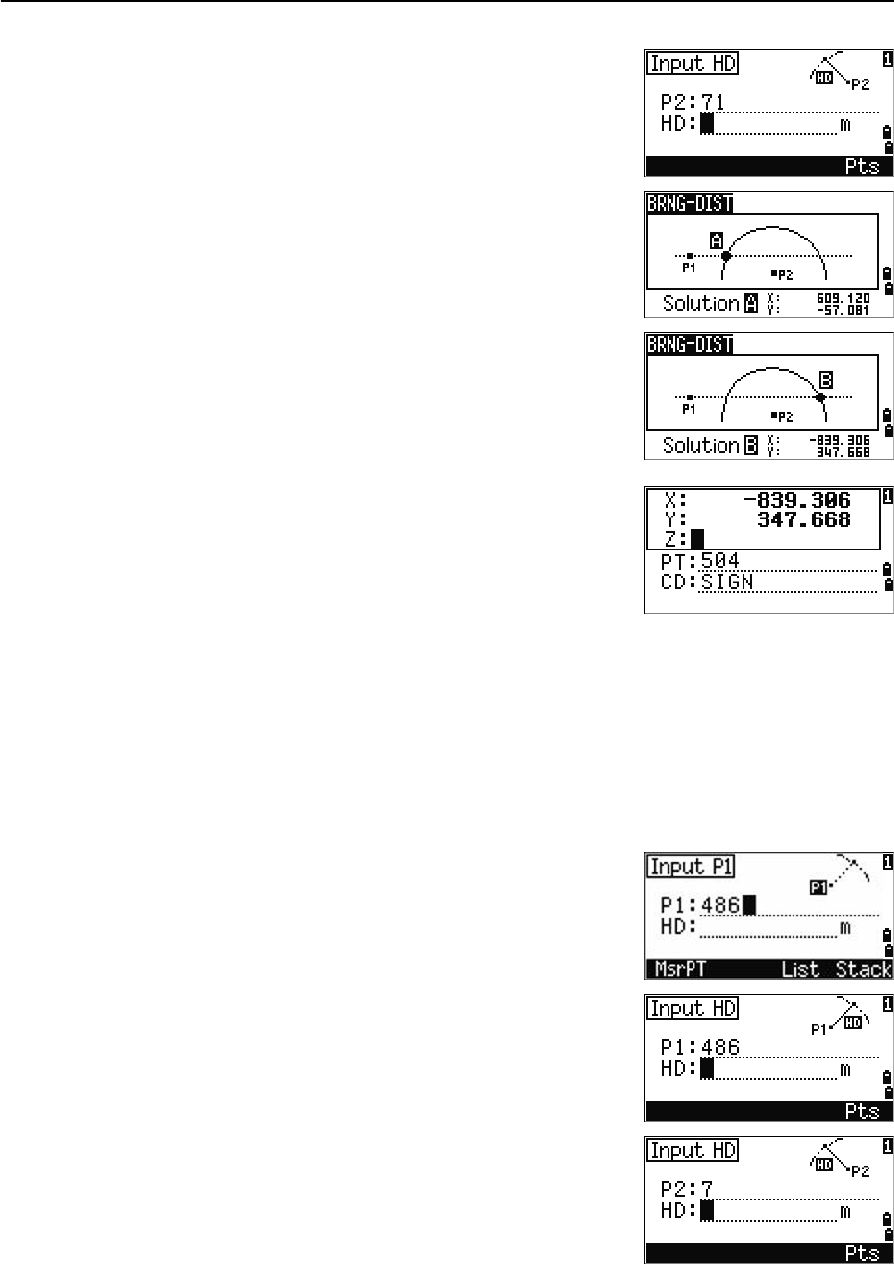
Total Station Nivo Series Instruction Manual 105
Menu Key 5
4. Enter the distance from P2.
–To define the distance (HD) by two points,
press the Pts softkey.
–To calculate the coordinates of the
intersection point, press [ENT] in the HD
field.
5. If there are two results, the first solution appears
graphically relative to the P1-P2 line. To display
the second solution, press [<] or [>].
6. To record the point, press [ENT] when the required
solution appears.
7. Enter a Z coordinate if necessary.
8. To move to the PT and CD fields, press [ENT].
Sample records
CO,Int BD P1:4672 AZ:330.54175+0.00000
CO, P2:71 HD:100.0000
CC,504,,-839.3065,347.6682,,SIGN
Calculating a distance-distance intersection
1. Press [3] or select Dist-Dist in the Intersection menu.
2. Enter the first point name and press [ENT], or
press the MSR softkey to measure directly to the
point.
3. Enter the distance from P1 and press [ENT].
4. To define the distance (HD) by two points, press
the Pts softkey.
5. Enter P2 and the distance from P2 (HD).
6. To calculate the coordinates of the intersection
point, press [ENT] in the HD field.
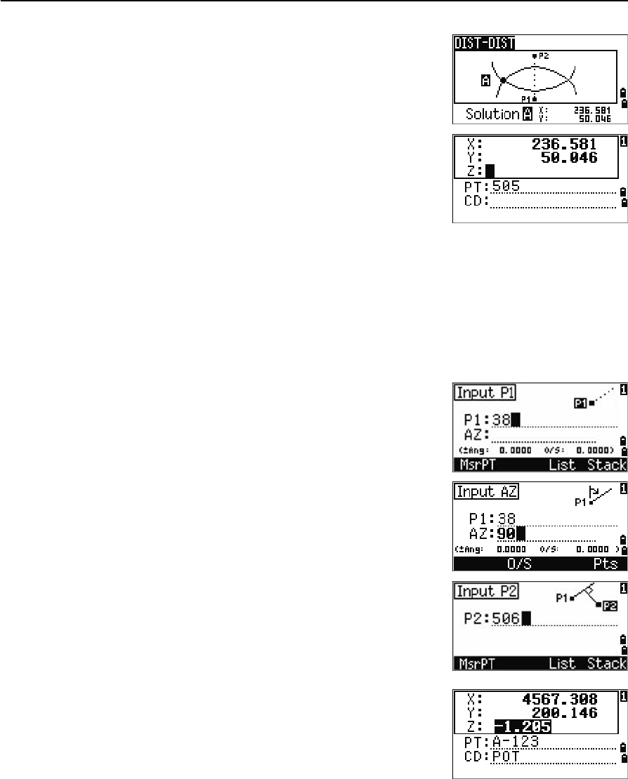
5 Menu Key
106 Total Station Nivo Series Instruction Manual
7. Press [<] or [>] to display the second solution.
8. To record the point, press [ENT] when the required
solution appears.
9. Enter a Z coordinate if necessary. Press [ENT] to
move to the PT and CD fields.
Sample records
CO,Int DD P1:486 HD:330.6020
CO, P2:7 HD:100.0000
CC,505,,236.5817,50.0461,0.0000,
Calculating a point-line intersection
1. Press [4] or select Pt-Line in the Intersection menu.
2. Enter the first point name and press [ENT], or
press the MSR softkey to measure directly to the
point.
3. Enter the azimuth, or press the Pts softkey to
enter another point name on the line.
4. Enter the perpendicular point to the line, or press
the MSR softkey to take a measurement to the
point.
5. To calculate the coordinates of the intersection
point, press [ENT].
If P1 and P2 are 3D points, the Z coordinate of
the perpendicular point is calculated relative to
the P1-P2 slope.
6. Enter PT and CD then press [ENT] to record the
point.
Sample records
CO,Int PtLine P1:38 AZ:90.00000+0.00000
CO, P2:506
CC,A-123,,4567.3080,200.1467,-1.2056,POT
Total Station Nivo Series Instruction Manual 107
Menu Key 5
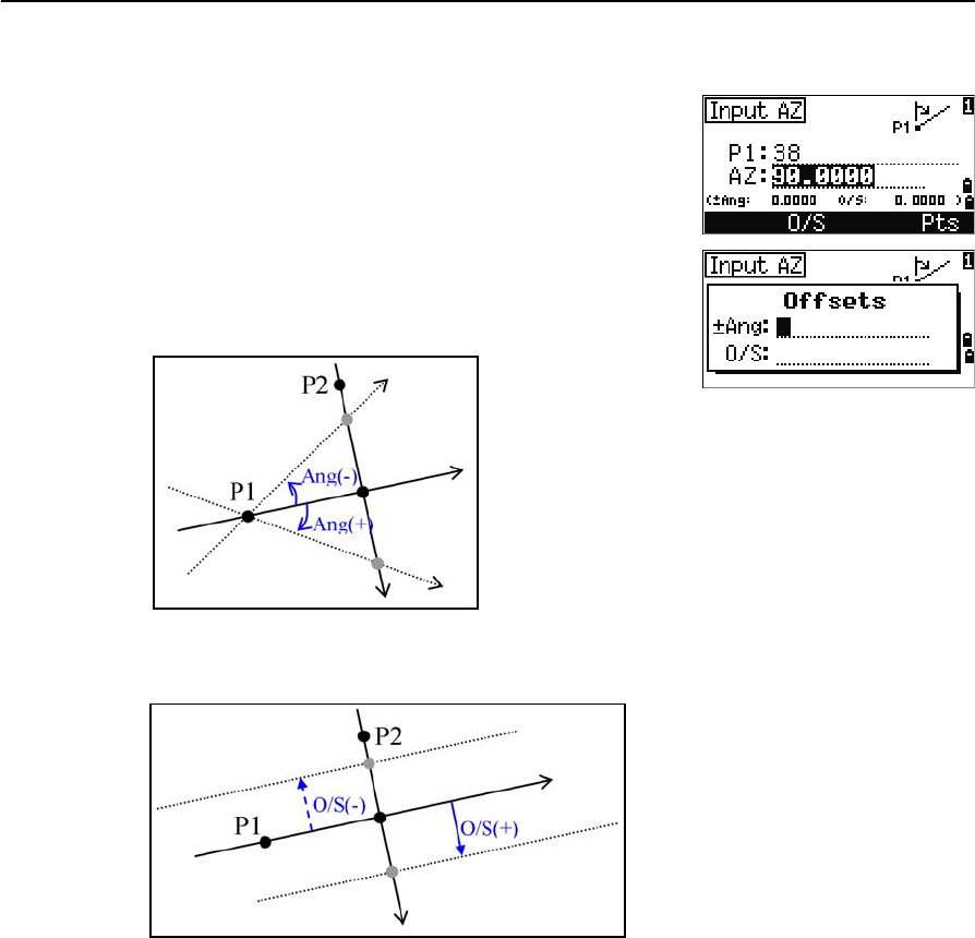
Advanced feature: Entering angle and distance offsets
To display the offset input screen, press the O/S
softkey.
In the Ang field, enter a positive value to rotate the line
clockwise. Enter a negative value to rotate the line
counterclockwise.
In the O/S field, enter a positive value to specify an offset to the right. Enter a
negative value to specify an offset to the left.
5 Menu Key
108 Total Station Nivo Series Instruction Manual
Settings
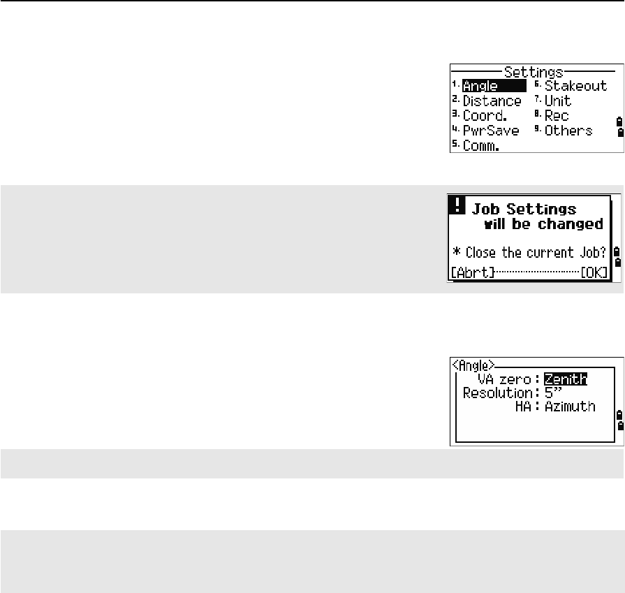
To display the Settings menu, press [2] or select
Settings on the MENU screen.
Use this menu to configure the initial job settings.
Angle
To open the Angle menu, press [1] or select Angle in
the Settings menu.
Some job settings, specified in the following sections, cannot be changed
once a job is created. If any of these settings are changed while a job is open,
a confirmation screen appears, asking you to create a new job with the new
settings, or to work with those settings without recording any data. For more
information, see Settings, page 174.
VA zero Zenith/Horizon/Compass
The VA zero job setting cannot be changed once a job is created.
Resolution 1"/5"/10" or 0.2 mgon/1 mgon/2 mgon
HA 0 to BS/Azimuth
The HA job setting cannot be changed once a job is created.
When this field is set to Azimuth, the horizontal angle (HA) that appears and recorded is in Azimuth value. When
this field is set to 0 to BS, HA is in HA zero to BS value.
Total Station Nivo Series Instruction Manual 109
Menu Key 5
Distance
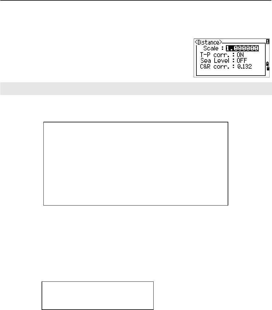
To open the Distance menu, press [2] or select Distance in the Settings menu
Temperature and Pressure corrections
Sea Level correction
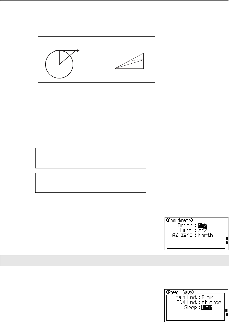
Curvature and Refraction correction
Because the surface of the earth is curved, the vertical difference (VD and Z) at the
measurement point, as referenced to the horizontal plane, inevitably includes some
error. This error is called curvature error. Also, because the density of the air
Scale Numeric value between 0.999600 and 1.000400
T-P corr. ON/OFF
Sea Level ON/OFF
C&R corr. OFF/0.132/0.200
The Scale, T-P corr., Sea Level, and C&R corr. job settings cannot be changed once a job is created.
SD Slope dist. (before adj.)
SD' Slope dist. (after adj.)
K Compensation coefficient
P Pressure (hPa)
T Temperature (°C)
HD Horizontal dist. (before adj.)
HD' Horizontal dist. (after adj.)
ZSTN Instrument-Z
Re6370 km
K275
106 P 10000.0
13.5951 980.665×
---------------------------------------------
©¹
§·
××
273 T+
---------------------------------------------------------------------------
–=
SD' 1 K
1000000
---------------------+
©¹
§·
SD×=
HD' HD Re
×
ReZSTN
+
------------------------
=
5 Menu Key
110 Total Station Nivo Series Instruction Manual
surrounding the earth decreases with altitude, light is refracted at different rates at
different altitudes. The error caused by this change in refraction is called refraction
error.
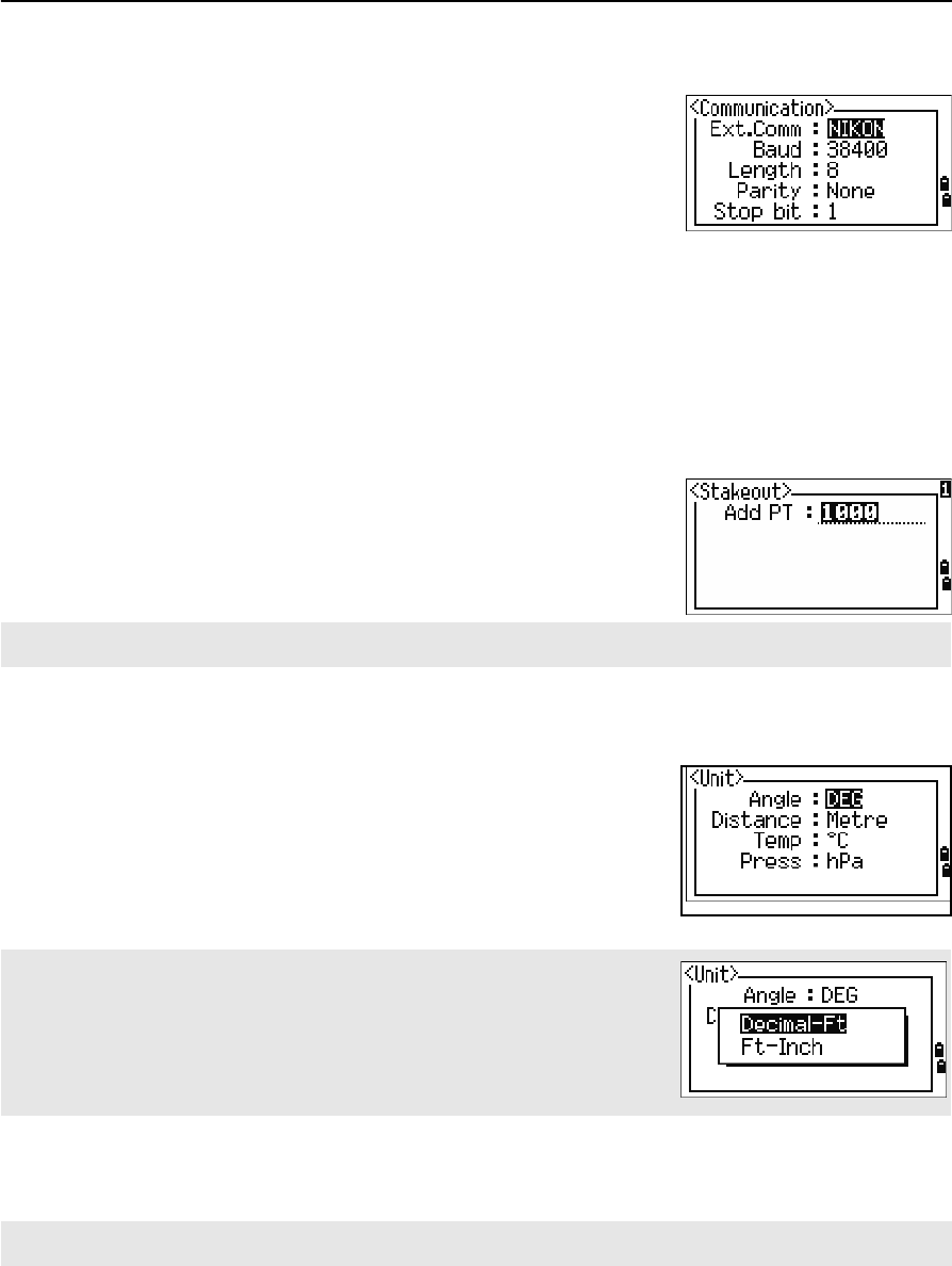
Coordinate
To open the Coordinate menu, press [3] or select
Coord. in the Settings menu.
Power saving
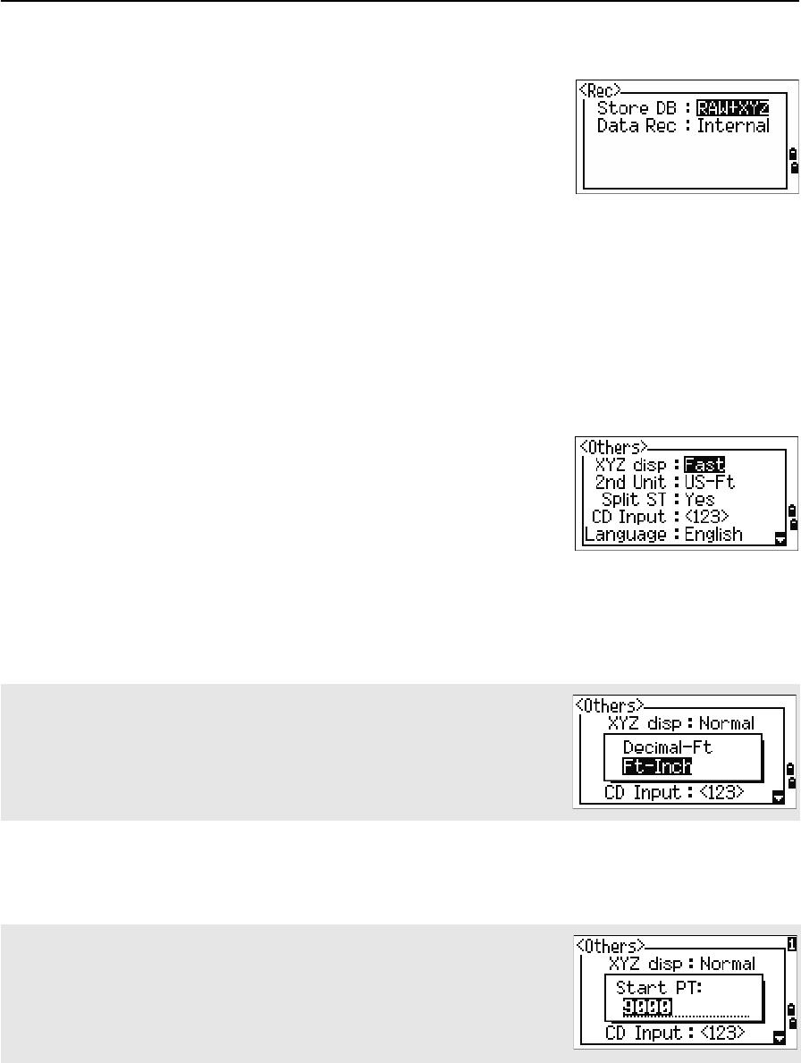
To open the Power Save menu, press [4] or select
PwrSave in the Settings menu.
HD Horizontal dist. (before adj.)
HD’ Horizontal dist. (after adj.)
VD Vertical dist. (before adj.)
VD' Vertical dist. (after adj.)
SD Slope distance
VA Vertical angle
Re 6370 km
k C&R constant (0.132 or 0.200)
Order NEZ/ENZ
Label XYZ/YXZ/NEZ(ENZ)
AZ North/South
The Order and AZ job settings cannot be changed once a job is created.
Main Unit OFF/5min/10min/30min
EDM Unit OFF/At once/0.1min/0.5min/3min/10min
Sleep OFF/1min/3min/5min
Curvature error (A A') Refraction error (A A1')
PA'Horizontal
direction
A
OP
A1'
A1
A'
HD' HD SD22VA()sin
2Re
----------------------------------- 1 k
2
---–
©¹
§·
–=
VD' VD HD2
2Re
-----------1 k–()+=
Total Station Nivo Series Instruction Manual 111
Menu Key 5
Communications
To open the Communication menu, press [5] or select
Comm. in the Settings menu.
Stakeout
Press [6] or select Stakeout in the Settings menu to
open the Stakeout menu.
.
Unit
To open the Unit menu, press [7] or select Unit in the
Settings menu.
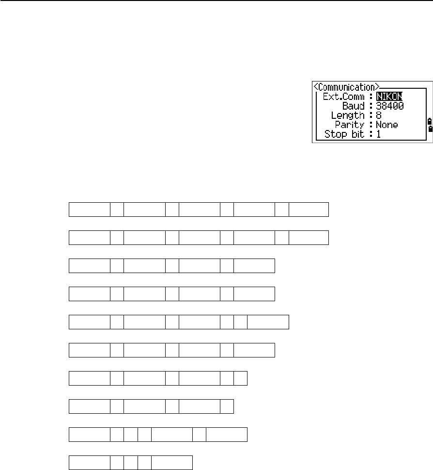
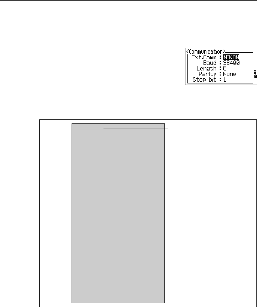
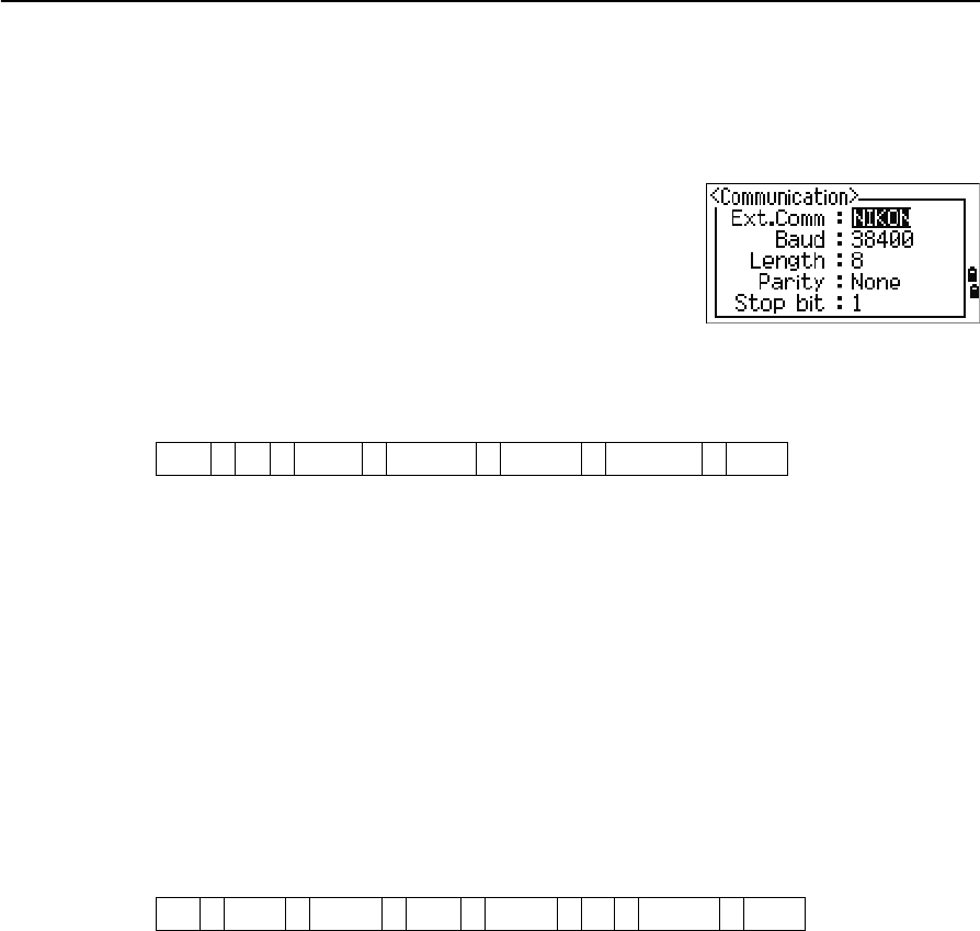
Ext.Comm NIKON/SET
Port Serial/Bluetooth (*)
Baud 1200/2400/4800/9600/19200/38400 bps
Length 7/8
Parity EVEN/ODD/NONE
Stop bit 1/2
(*) Port selection field appears only when the optional
Bluetooth is on-board.
Add PT Integer between 1 and 999,999
This field sets the default point number to record observed data in stakeout.
Angle DEG (Degree)
GON (GON)
MIL (Mil6400)
Distance Meter/US-Ft/I-F
If you select US-Ft or I-Ft, an additional settings screen appears. Use this
screen to specify whether to display values in Decimal-Ft or
Ft-Inch.
Temp °C (Celsius)
°F (Fahrenheit)
Press hPa/mmHg/inHg
The Angle, Distance, Temp, and Press job settings cannot be changed once a job is created.
5 Menu Key
112 Total Station Nivo Series Instruction Manual
Recording
To open the Rec menu, press [8] or select Angle in the
Settings menu.
Others settings
To open the Others menu, press [9] or select Others in
the Settings menu.
Store DB RAW/XYZ/RAW+XYZ
This setting determines whether raw and/or
coordinate data is stored when you record SS,
CP, or SO records in the Basic Measurement
Screen (BMS) or Stakeout screen.
Data Rec Internal/COM
Set this field to COM to output data on the COM
port when you press [ENT] in the BMS or a
Stakeout screen. The data is not stored to the
job file. For more information, see Outputting
data to the COM port, page 82
XYZ disp Fast/Norm/Slow/+ENT
Defines speed to move to the next screen after
showing XYZ of the input PT
2nd Unit None/Meter/US-Ft/I-Ft
When the Secondary unit is set to a unit, an
extra display screen is available in the BMS,
stakeout observation screens, and 2-pt
reference line screens. The extra screen shows
the HD, VD, and SD in the secondary unit.
If you select US-Ft or I-Ft, an additional settings screen appears. Use this
screen to specify whether to display values in Decimal-Ft or Ft-Inch.
Split ST No/Yes
Select Yes to separate the point numbers of
station points from other record type point
numbers
If you set the Split ST field to Yes, an additional setting screen appears. Use
this screen to specify the starting ST number.
Total Station Nivo Series Instruction Manual 113
Menu Key 5
BTip – To provide easier configuration for common regional settings, you can quickly configure
the Nikon total station to a pre-set combination of default regional settings. For more
information, see Changing Regional Configuration Pre-sets, page 25.
BTip – The Nikon total station supports up to 3 languages on the instrument. For more
information on changing the language settings, see page 113.
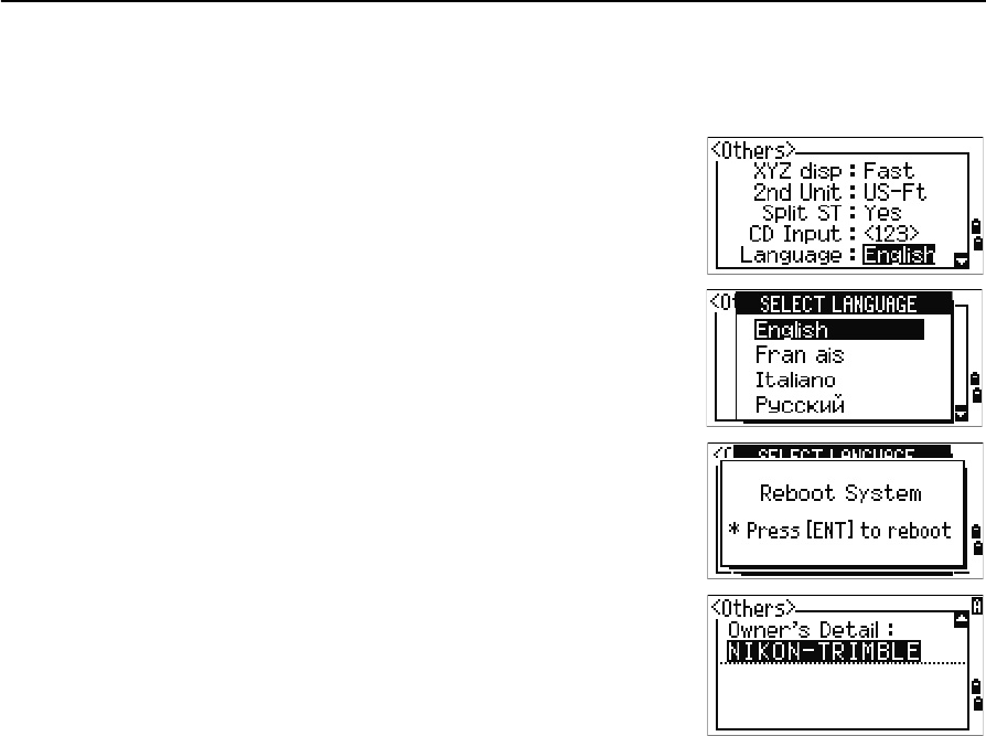
CD Input ABC/123
Sets the default input mode when a CD field
appears.
Language Select a language from the list.
Press [<] /[>] to open the select language
screen.
Press [^] /[v] to move the cursor to the desired
language, and press [ENT] to select it.
Reboot confirmation screen appears.
Press [ENT] and re-start the instrument, and
the selected language will be available.
Owner’s Detail Up to 20 characters.
Enter your name or the name of your
company. If you enter a value in this field, it
appears at start-up.
5 Menu Key
114 Total Station Nivo Series Instruction Manual
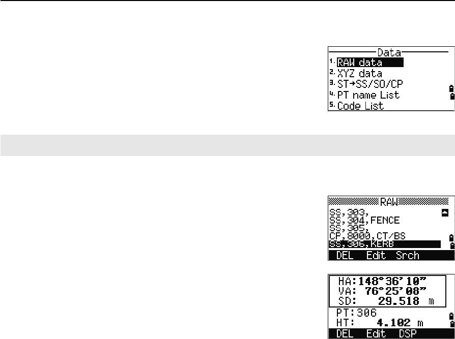
Data
Use the Data menu to view or edit records. To display
the Data menu, press [4] on the MENU screen.
Viewing records
Viewing raw data
To show the raw data records in a list, press [1] on the
Data menu screen.
When you first view the raw data, the last four raw
records in the current job are displayed. Use [^] or [v] to
scroll through the records.
To see detailed information for the selected records,
press [ENT].
To return to the record list, press [ESC].
SS, CP, F1 records
Raw SS, CP and F1 records contain PT, HT, CD, HA, VA, and SD fields.
SS records are sideshots (topo shots). All shots from the Basic Measurement Screen
(BMS) are stored as SS records.
CP records are shots taken in the Angle or Repeat menus, or in the BMS. For more
information, see Recording a foresight point after repeat angle measurement, page 52,
and Recording data from any observation screen, page 81.
When the Store DB setting is set to RAW+XYZ, press [DSP] to switch between the first
screen (showing HA, VA, SD, PT, and HT) and the second screen (showing X, Y, Z,
PT, and CD).
Coordinates are not available in F1 records.
When you take more than one measurement to the same point and choose to
overwrite the XYZ data, the old raw record becomes raw data only. As a result, only
one SS(RAW) record keeps its corresponding SS(XYZ) record. Other SS(RAW)
records to the same point no longer have coordinates available.
You can view data at any time, even in an observation screen or while entering points.
Total Station Nivo Series Instruction Manual 115
Menu Key 5
ST records
ST (station) records contain ST, HI, BS, and AZ fields.
Press [DSP] to switch between the first screen (showing ST, HI, BS, and AZ) and the
second screen (showing X, Y, Z, PT, and CD).
When you assign a new ST point name in MENU > Stn Setup > Quick, the
coordinates of the station is recorded as (0, 0, 0).
SO records
SO records are stakeout shots. These are shots recorded in stakeout functions.
When the Store DB setting is set to RAW+XYZ, press [DSP] to switch between the first
screen (showing HA, VA, SD, PT, and HT), the second screen (showing X, Y, Z, PT,
and CD), and the third screen (showing dX, dY, dZ, PT, and CD).
The dX, dY, and dZ fields store the difference between the stakeout shot’s actual
position and its planned position. These fields are downloaded as comment records in
Nikon RAW format.
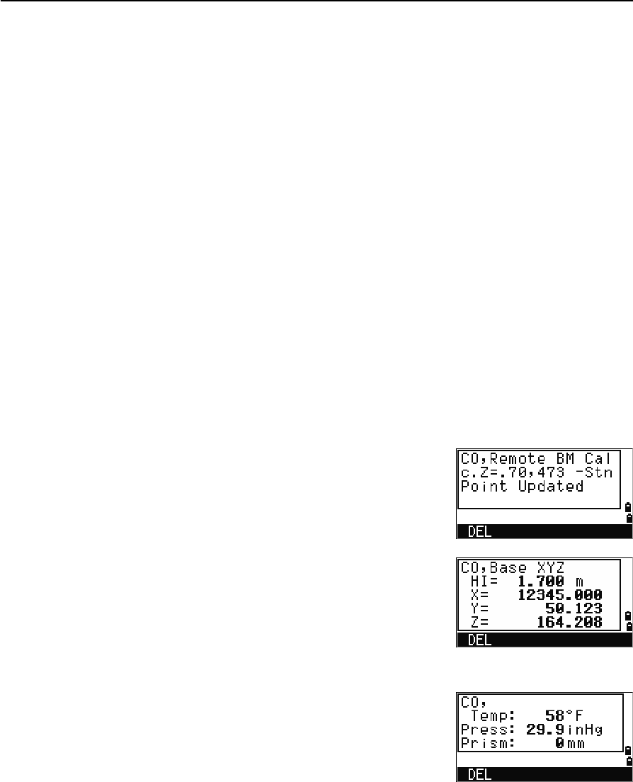
CO records
A CO record is a comment added to the job from the system.
For example, when you change the Stn-Z using the
Remote Benchmark function, or you reset the
horizontal angle using the BSCheck function, the
system writes a comment record.
When you input a Stn-XYZ by Base-XYZ function, the
recorded station appears as a comment record.
SY records
When you complete a station setup, a SY record is
stored. This record contains the Temperature, Pressure,
and Prism Constant values.
5 Menu Key
116 Total Station Nivo Series Instruction Manual
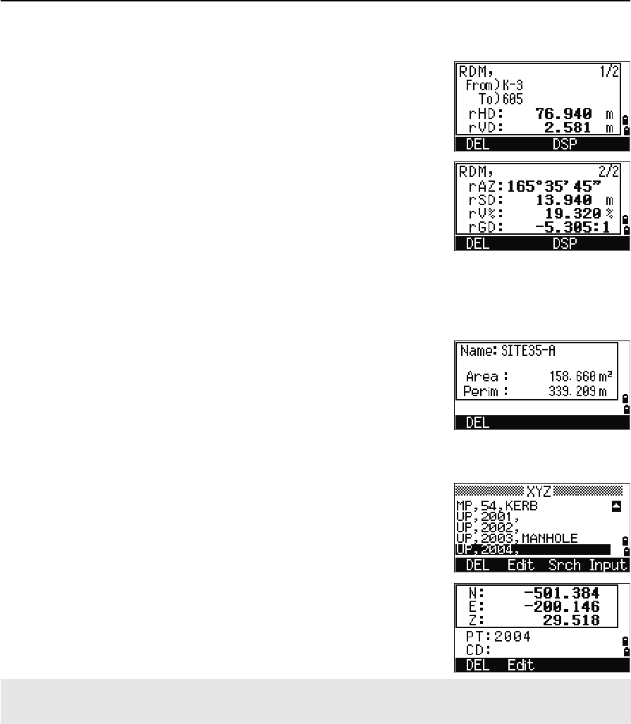
RM records
When you record measurements in RDM (Cont) or
RDM (Rad), they are labeled as RM records.
Each RM record consists of two screens.
Press [DSP] to switch between the first screen (showing
From, To, rHD, and rVD) and the second screen
(showing rAZ, rSD, rV%, and rGD).
When you download data in Nikon RAW format, RM
records are output as comment (CO) records.
AR records
An AR record stores an area and perimeter calculation.
When you download data in Nikon RAW format, AR
records are output as comment (CO) records.
View coordinate data
When you press [2] or select XYZ data in the Data
menu, coordinate data appears in a list, with the newest
record at the bottom of the screen. Use [^] or [v] to scroll
through the records. Use [<] or [>] to move up or down
one page.
Press [ENT] to see more detailed information about the
selected record.
UP, MP, CC, and RE records
All coordinate records contain PT, CD, X, Y, and Z fields.
UP records are uploaded point coordinates. MP records are manually input point
coordinates. CC records are points calculated in Cogo, and RE records are points
calculated in Resection.
The header (XYZ,YXZ,NEZ, or ENZ) depends on the Coord. Label setting in MENU > Settings >
Coord. For more information, see Coordinate, page 110.
Total Station Nivo Series Instruction Manual 117
Menu Key 5
When the Store data setting is set to RAW+XYZ or to XYZ, shots in the BMS (SS
records), in various O/S functions (SS records), in 2Pt-RefLine and Arc-RefLine in
PRG (SS records) and in some Stakeout functions (SO records) store coordinate
records as well. The format of the data is the same as other coordinate records.
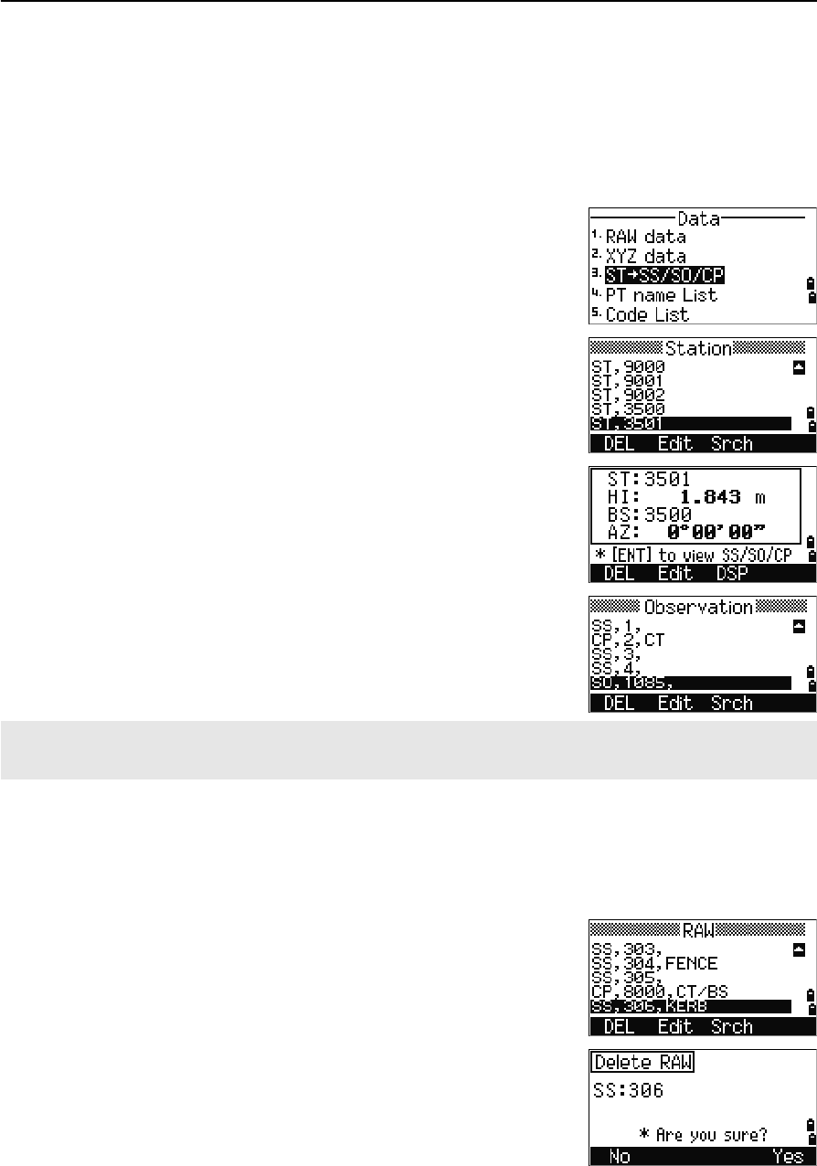
View records by station
To view records by station, press [3] or select
ST->SS/SO/CP in the Data menu.
A list of all stations appears.
Use [^] or [v] to highlight the station name that you want
to view. Use [<] or [>] to move up or down one page.
To view detailed information about the selected station,
press [ENT].
To display all the observation data from the selected
station in chronological order, press [ENT] again.
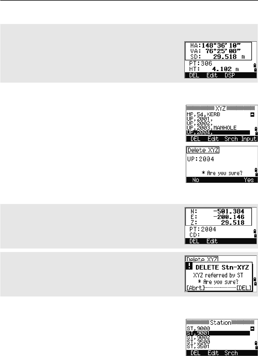
Deleting records
Deleting raw records
In the RAW screen, use [^] or [v] to highlight the record
that you want to delete. Then press the DEL softkey.
A confirmation screen appears. To delete the selected
record, press [ENT] or the Yes softkey.
Detailed data is as for raw data. For detailed information about each point type and format, see Viewing raw
data, page 114.
5 Menu Key
118 Total Station Nivo Series Instruction Manual
Deleting coordinate records
In the XYZ screen, use [^] or [v] to highlight the record
that you want to delete. Then press the DEL softkey.
A confirmation screen appears.
To delete the selected record, press [ENT] or the Yes
softkey.
To cancel the deletion of data, press [ESC] or the No
softkey.
Deleting station records
In the Station screen, use [^] or [v] to highlight the record
that you want to delete. Then press the DEL softkey.
If the Store DB setting is set to Both, the system also deletes the corresponding coordinate data when you
delete an SS, SO, or CP record.
You can also delete raw data by pressing the DEL softkey in the detailed
display screen for the record.
You can also delete coordinate data by pressing the DEL softkey in the
detailed display screen for the record.
If the record that you want to delete is referred by an ST record, a confirmation
message appears.
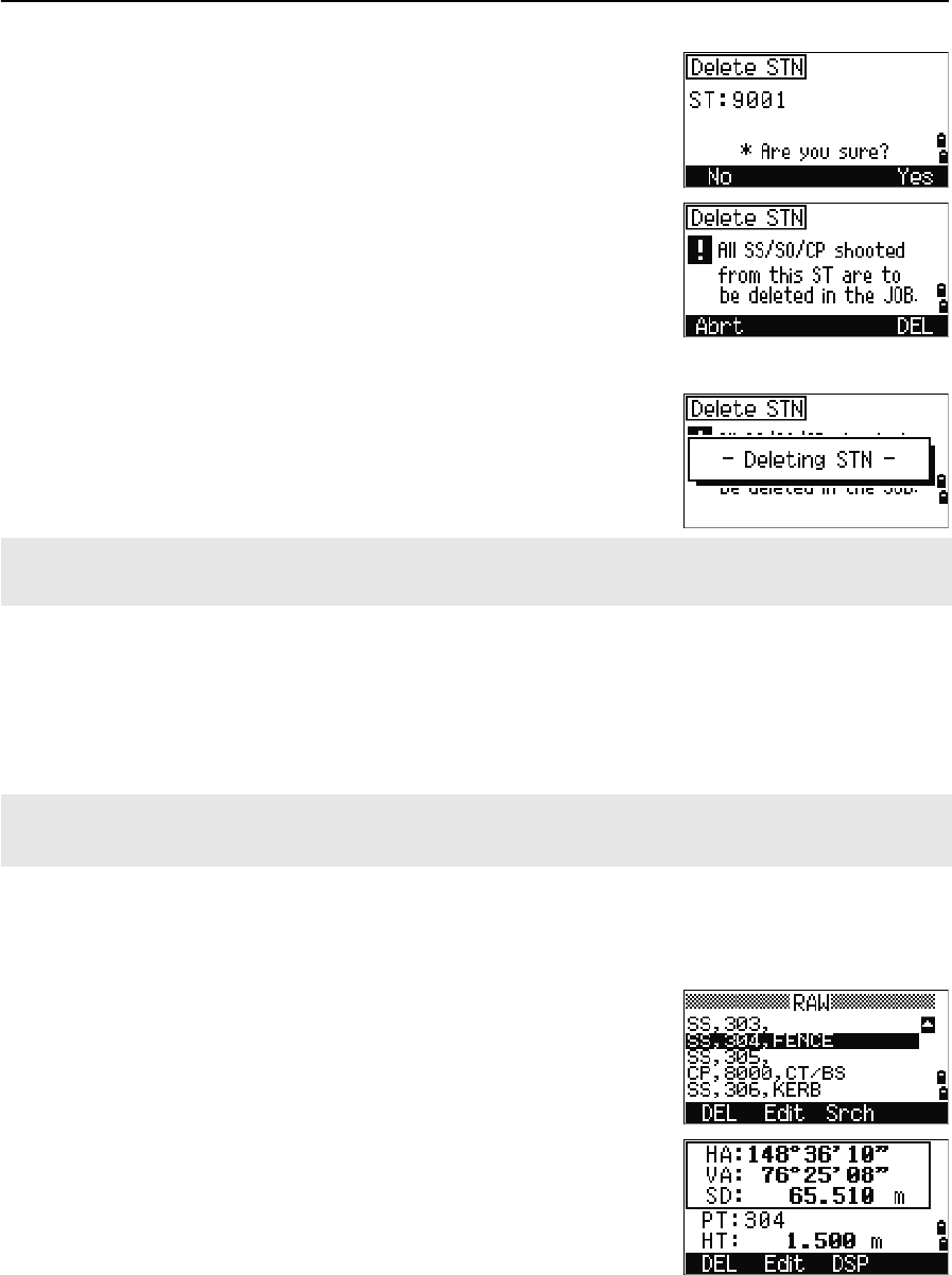
Total Station Nivo Series Instruction Manual 119
Menu Key 5
A confirmation screen appears.
Press [ENT] or the Yes softkey to delete the selected
record.
A reconfirmation screen appears. Press the DEL
softkey to confirm deletion.
There is no undelete function on the instrument. Before
you press the DEL softkey, make sure that you have
selected the correct station record. You cannot press
[ENT] in this screen.
All observations from the station that you selected are
deleted.
Editing records
For any point record, you can edit the point name (PT), feature code (CD), height of
target (HT), height of instrument (HI), backsight point (BS), and backsight azimuth
(AZ).
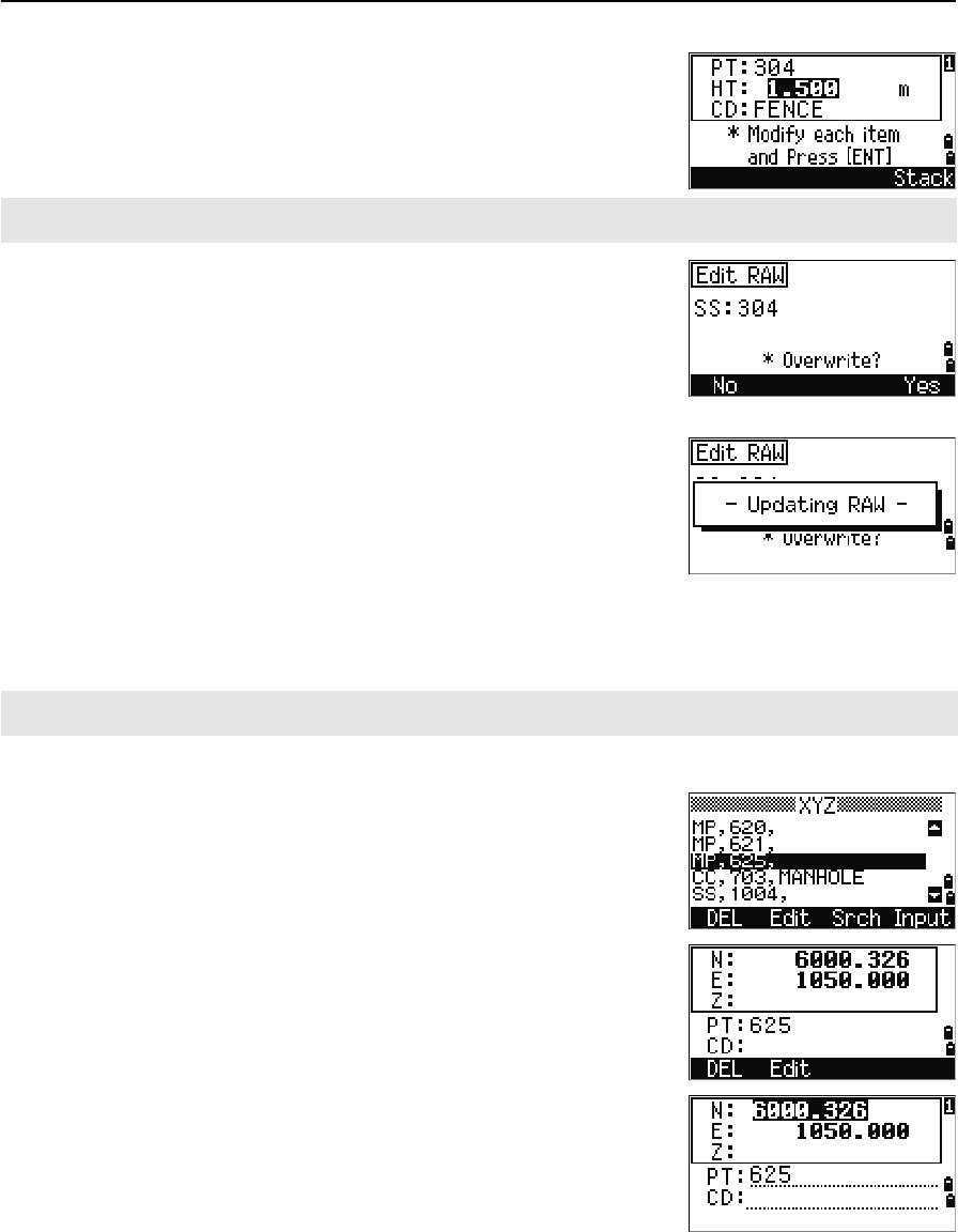
Editing raw records
1. Do one of the following:
–In the RAW screen, highlight the record
that you want to edit. Then press the Edit
softkey.
–In the detailed data screen, press the Edit
softkey.
When you delete a ST record in the raw data view or the station data view, all the observation data from the
station is also deleted.
You cannot edit the CD field for SO or F1 records.
You cannot edit the HA, VA, or SD values.
5 Menu Key
120 Total Station Nivo Series Instruction Manual
2. Use [^] or [v] to highlight a field. Then modify the
value in the selected field.
3. When you press [ENT] on the last line of the edit
screen, a confirmation screen appears.
4. Do one of the following:
–To accept the changes and return to the data
view screen, press [ENT] or the Yes softkey.
–To return to the edit screen, press [ESC] or
the No softkey.
Editing coordinate records
You can edit PT, CD, and coordinate values in coordinate records.
1. Do one of the following:
–In the XYZ screen, use [^] or [v] to highlight
the record that you want to edit. Then press
the Edit softkey.
–In the detailed data screen, press the Edit
softkey.
2. Use [^] or [v] to highlight a field. Then modify the
value in the selected field.
3. To finish editing, press [ENT] in the CD field.
When you change the HT of an SS, SO, or CP measurement record, its Z coordinate is recalculated.
You cannot edit the coordinate record for the current station.
Total Station Nivo Series Instruction Manual 121
Menu Key 5
A confirmation screen appears.
4. Do one of the following:
–To accept the changes and return to the data
view screen, press [ENT] or the Yes softkey.
–To go back to the edit screen, press [ESC] or
the No softkey.
Editing station records
Note – The system will not recalculate measurements if you change the station record.
All coordinate and raw data observed from an edited station record must be
recalculated in your postprocessing software.
In the RAW screen, use [^] or [v] to highlight the station
record that you want to edit. Then press the Edit
softkey.
You can edit any field in the ST record, but the
instrument does not recalculate any measurements
from this station.
Press [ENT] in the AZ field to confirm the change.
If you change the ST or HI values, the coordinates of observation points are not recalculated. A comment record
is stored to record the change. The following example shows a comment record for a changed HI value:
CO,HI changed at ST:9012 Old HI= 1.345m
If you change the BS or AZ values, raw records are not recalculated. A comment record is stored to record the
change.
5 Menu Key
122 Total Station Nivo Series Instruction Manual
Searching records
You can search for records by their type, point name, code, or by any combination of
these values.
Searching raw records
In the RAW screen, press the Srch softkey to access
the raw data search function.
To find a point by name, enter the name in the PT field
and press [ENT] twice.
You can use the asterisk (*) as a wildcard. For
example, when you enter 30* in the PT field, the
search matches the points named 300, 301, 302,
3000A2, and 3010.
If more than one point matches the search criteria, the
matching points are displayed in a list.
Use [^] or [v] to highlight the point you want to use. Then
press [ENT] to select it.
Detailed data for the selected record appears. Press the
DSP softkey to change the fields shown.
Press [ESC] to return to the list.
To search by point type, move to the Type field and use [<] or [>] to change the
selected point type. The options are ALL, ST, SS, SO, CP, CO, CO(SY), and
CO(RDM).
If you selected ST, SO or F1 in the Type field, you do not have to enter a value in the CD field. Press [ENT] in the
PT field to start the search.
If you selected CO, CO(SY), or CO(RDM) in the Type field, you cannot enter a value in the PT or CD fields.
Press [ENT] in the Type field to start the search.
Total Station Nivo Series Instruction Manual 123
Menu Key 5
Searching coordinate records
In the XYZ screen, press the Srch softkey to access
the XYZ data search function.
To find a coordinate by name, enter the name in the PT
field and press [ENT] twice.
You can use the asterisk (*) as a wildcard. For
example, when you enter 500* in the PT field, the
search matches the points named 500, 500-1, 500-A,
and 5000.
If more than one point matches the search criteria, the
matching points are displayed in a list.
Use [^] or [v] to highlight the point you want to use. Press
[ENT] to select it.
Detailed data for the selected record appears. Press the
DSP softkey to change the fields shown.
Press [ESC] to return to the list.
If no point matches the specified criteria, an error screen appears. Press any
key to return to the data screen.
To search by point type, move to the Type field and use [<] or [>] to change the
selected point type. The options are ALL, MP, UP, CC, and RE.
5 Menu Key
124 Total Station Nivo Series Instruction Manual
Entering coordinates
In the XYZ screen, press the Input softkey to display
a new input point screen.
The PT field defaults to the last recorded PT + 1, but
you can change the value shown.
Enter the PT and CD and then press [ENT] to enter
coordinates.
Use the numeric keys to enter the coordinates. Press
[ENT] or [v] in each field to move to the next field.
When you press [ENT] in the CD field, the point is stored
as an MP record.
After you have recording a point, the next point input
screen is shown with the updated default PT.
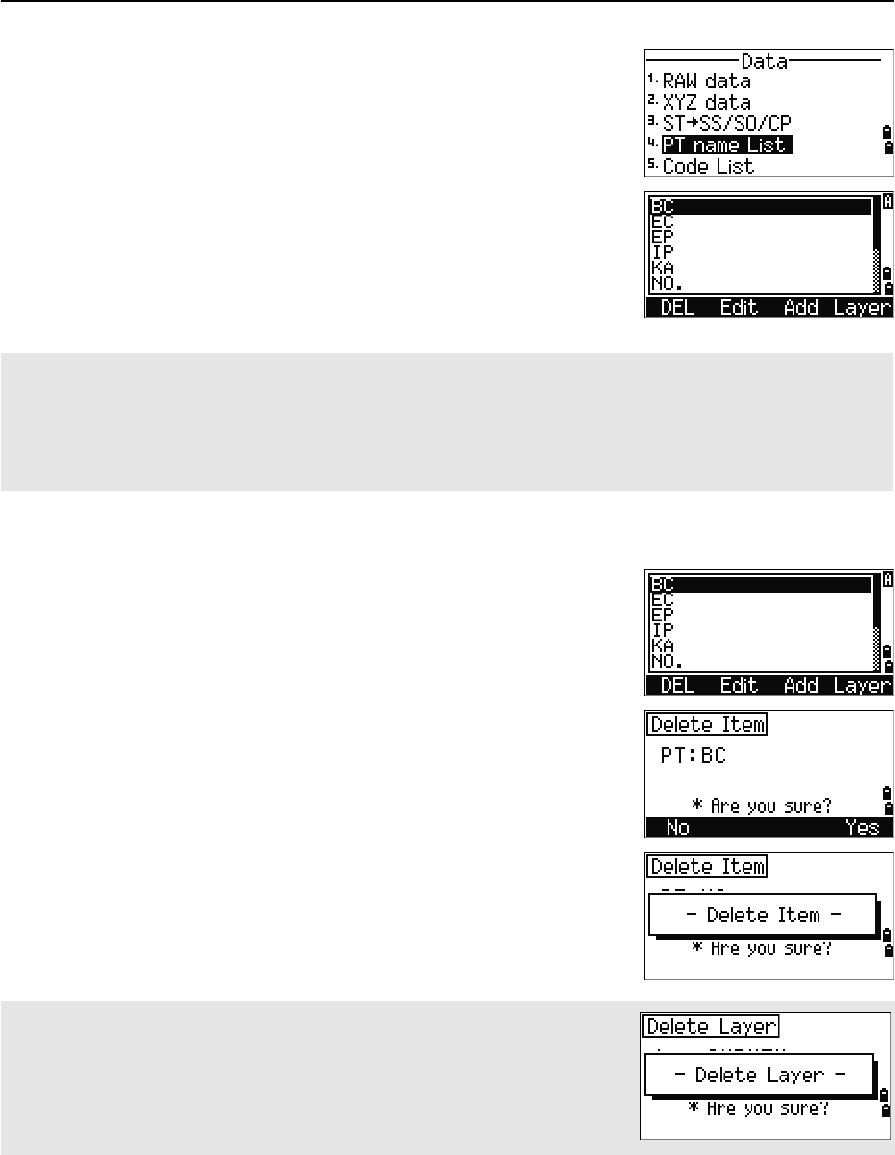
Point name list and code list
The instrument stores two list files: a list of PT names and a list of CD names. The
structure and functionality of these files is the same.
•The PT name list is useful if you have to handle more than one patterns of
point names in the field. For example, you may need to use points named 1, 2,
3 …, as well as points named A1, A2, A3 ….
•The code list is a prepared list of feature codes. You can use it to store your
own codes.
If no point matches the specified criteria, an error screen appears. Press any
key to return to the data screen.
You can record NE, NEZ, or Z-only data to the database.
Total Station Nivo Series Instruction Manual 125
Menu Key 5
Press [4] or select PT name List in the Data menu to
open the point name list.
Press [5] or select Code list to open the code list.
The point or code names and layers are shown in
alphabetic order. Use the four softkeys to customize
the list.
Deleting points, codes, or layers
In the point or code list, use [^] or [v] to highlight the
item you want to delete. Then press the DEL softkey.
A confirmation screen appears. Press [ENT] or the Yes
softkey to delete the item.
Press [ESC] or the No softkey to cancel the deletion.
You can store up to 254 points, codes, or layers in each list.
Each list entry can be up to 16 characters long.
You can use the first character search to find a point, code, or layer in the list. In the list screen, enter the first
character of the name you want to find to jump to that part of the list. For more information, see Advanced
feature: Searching for a code by using the first character, page 44.
To delete a whole layer, highlight the layer name in the list and press the DEL
softkey. All codes and layers in the selected layer are deleted.

5 Menu Key
126 Total Station Nivo Series Instruction Manual
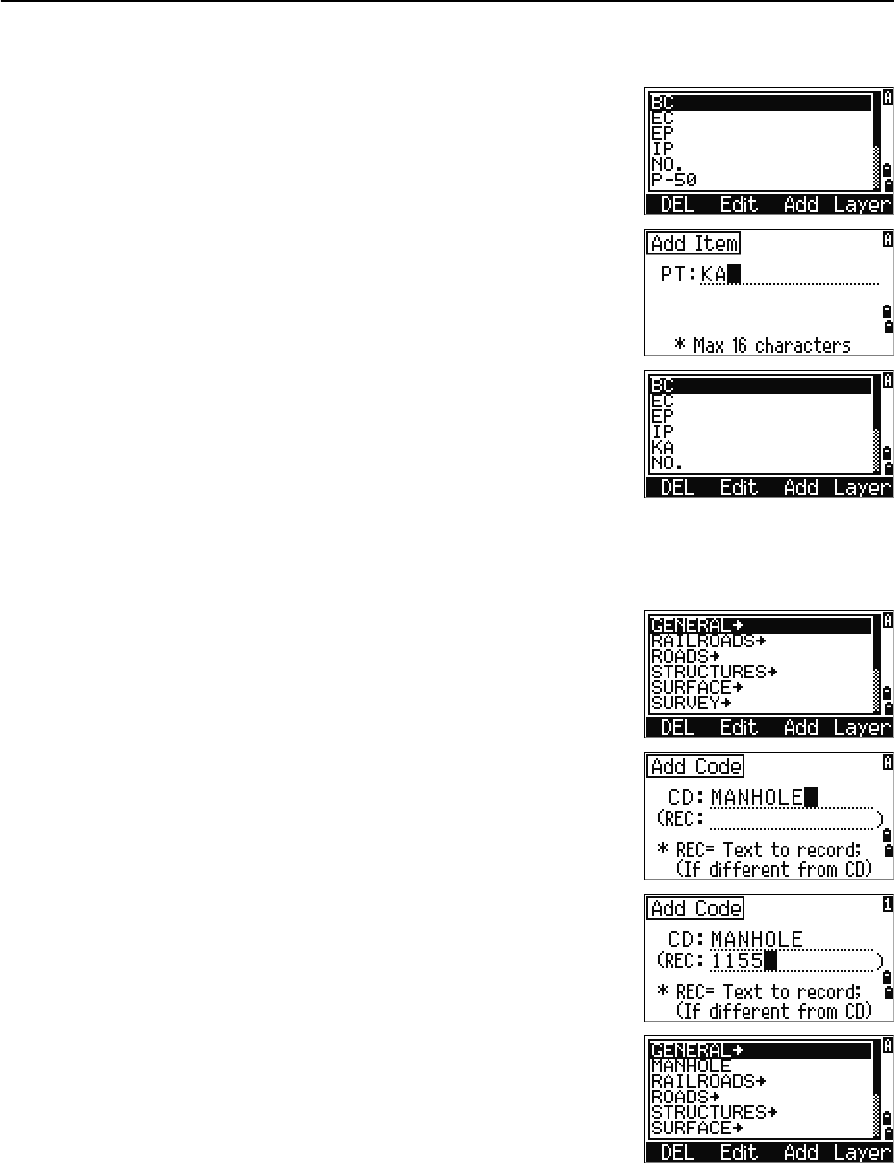
Editing an item in the point list or code list
Use [^] or [v] to highlight the item that you want to edit.
Then press the Edit softkey.
An editing screen appears. For points, the Edit Item
screen appears. It contains only the PT field. For codes,
the Edit Code screen appears, containing the CD field
and the REC field.
Edit the text shown and then press [ENT].
A confirmation screen appears. Press [ENT] or the Yes
softkey to accept the changes and update the list.
Edit code list
• The Edit Code screen has two fields. The CD field contains the text that
appears in the list screen. The REC field is optional. It contains the text
that is stored in the job. If you leave the REC field blank, the value in the
CD field is used.
• You can use the REC field to use familiar words or codes on the screen,
but store a numeric code in the job. For example, if you set the CD field to
MANHOLE and the REC field to 1155, the text MANHOLE appears on the
screen, but the code 1155 is stored.
If you press the Edit softkey when a layer name appears, only the Lyr field
appears. To save changes to the layer name, press [ENT] in the Lyr field.
Total Station Nivo Series Instruction Manual 127
Menu Key 5
Adding a point name
In the point list, press the Add softkey to add a new
point name to the current layer.
Enter a new point name and then press [ENT].
The point name is added to the current layer and the list
is updated.
Adding a code
In the code list, press the Add softkey to add a new
feature code to the current layer.
Enter the feature code in the CD field. Press [MODE] to
change between alphabetic and numeric input mode.
You can use the REC field to define a numeric
identifier for each feature code. This is optional: If
there is a value in the REC field, this value is stored. If
you leave the REC field blank, the CD value is stored.
Press [ENT] to add the new code and update the code list.
5 Menu Key
128 Total Station Nivo Series Instruction Manual
Adding a layer
1. In the point or code list, press the Layer
softkey.
2. Enter the name of the new layer.
3. To change between alphabetic and numeric input
mode, press [MODE]. To store the new layer, press
[ENT].
The new layer is added to the list in alphabetic
order.
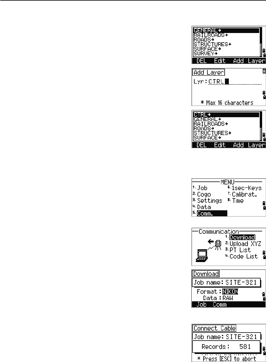
Communication
Use the Communication menu to download or upload
data. To display the Communication menu, press [5] or
select Comm. on the MENU screen.
Downloading data
To go to the download settings screen, press [1] or select
Download in the Communication menu.
Format NIKON
SDR2x
SDR33
Data RAW
Coordinate
To display the total number of records that will be
downloaded, press [ENT] in the Data field.
Total Station Nivo Series Instruction Manual 129
Menu Key 5
Optional Bluetooth function
When the optional Bluetooth is installed, Port selection
screen appears when pressing the Comm softkey.
As each record in the current job is output from the
instrument (downloaded), the current line number is
updated.
After downloading is completed, you can choose to
delete the current job.
To delete the current job, press [4]. To return to the
Basic Measurement Screen (BMS), press [ESC] or the
Abrt softkey.
Uploading coordinate data
To upload coordinate data from a computer, press [2] or
select Upload XYZ in the Communication menu.
The default data format appears. To change the order
of data fields, press the Edit softkey. For more
information, see Advanced feature: Editing the data
order for upload, page 130.
Otherwise, just press [ENT].
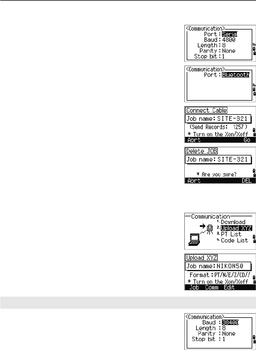
To change the communication settings, press the Comm
softkey. The serial port settings must match the settings
used by the terminal software on the computer.
Port selection field appears in the Communication
menu only when the optional Bluetooth is on-board.
Press the Job softkey to go to the Job Manager screen. For more information, see Job Manager, page 92.
5 Menu Key
130 Total Station Nivo Series Instruction Manual
Use an RS-232C cable to connect the instrument to the
computer.
The Free space field shows the number of points that
can be stored.
Press [ENT] to put the instrument in receive mode. Then
use the Send Text File command in the terminal program on the computer to start
sending data.
As each point is received by the instrument, the value
in the Records field is incremented.
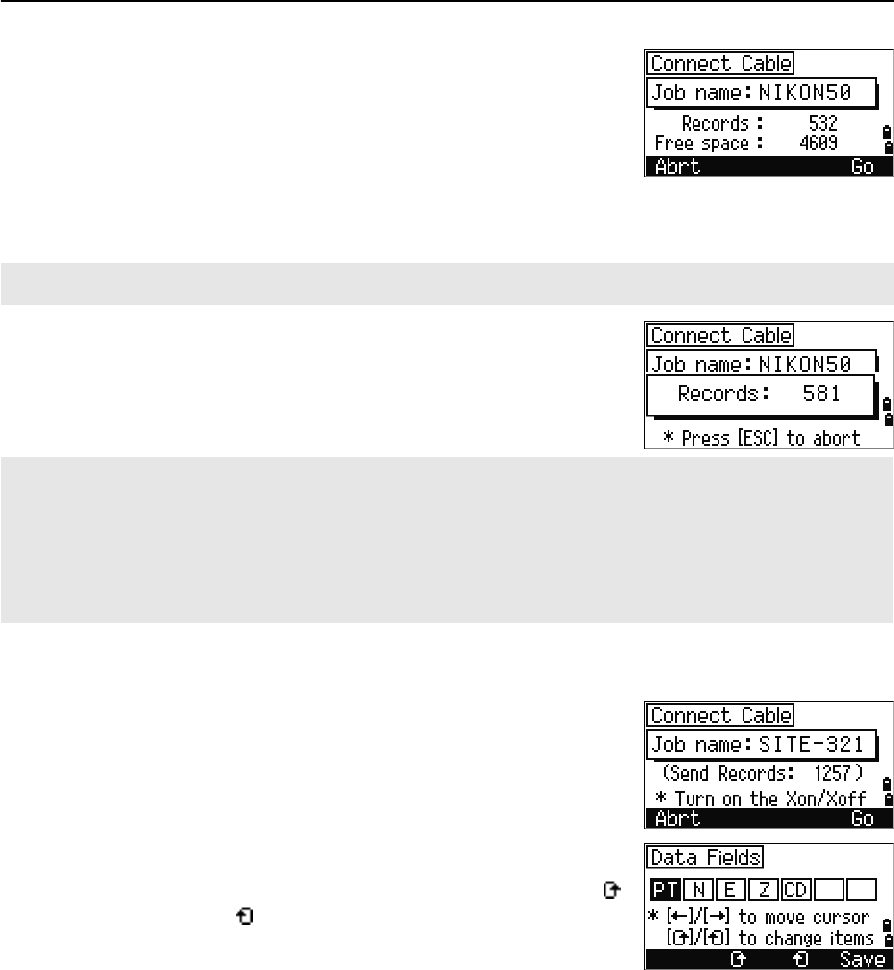
Advanced feature: Editing the data order for upload
1. To open the Data Fields screen, press the Edit
softkey.
2. To move between the fields, press [<] or [>].
3. To change the selected item in a field, use the
and softkeys. The options are PT, N, E, Z, CD,
or blank.
4. To save your changes and return to the previous
screen, press the Save softkey.
For example, if your original data is as follows:
and you set the data fields to PT N E CD, then the uploaded data is:
In the terminal program, set flow control to Xon/Xoff.
If you press [ESC] during data upload, the upload is canceled and the display returns to the Communication
menu. Records that were received before you pressed [ESC] are stored in the job.
The system truncates any code that is longer than 16 characters.
Duplicate points
If the existing point is a UP, CC, or MP record, and it is not referred to by any ST or BS, it is automatically
overwritten by the uploaded point. No error message appears.
1, UB, 30.000, 20.000, L1
PT=1, N=30.000, E=20.000, CD=L1
Total Station Nivo Series Instruction Manual 131
Menu Key 5
Uploading coordinates without points
You can upload data without points. If you do not include a point in the format
definition, each line of data is automatically assigned the next available point number.
To help you to select points in the field, make sure that you store an identifier in the
CD field.
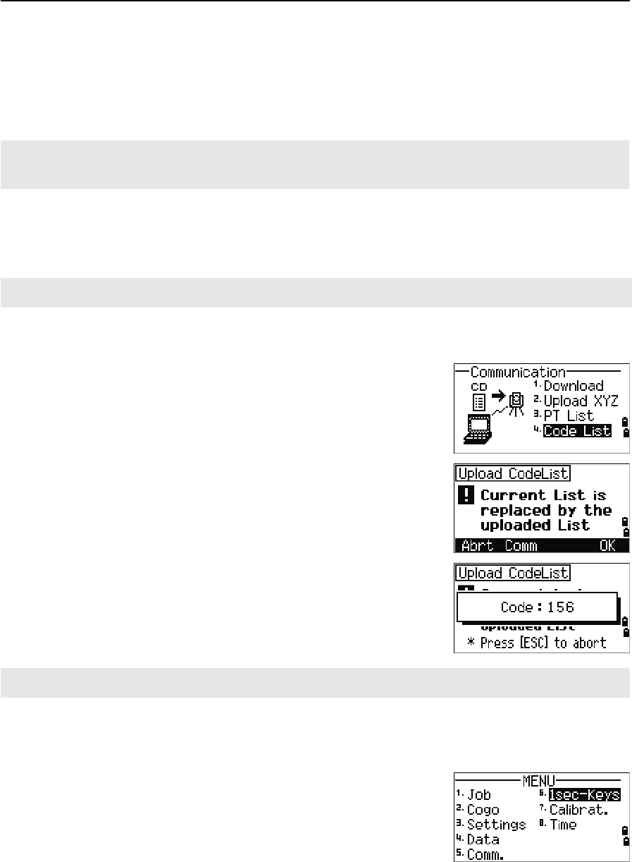
Uploading a point name list or code list
To upload a point name list via cable, press [3] or select PT List in the
Communication menu.
To upload a code list, press [4] or select Code List.
Connect the RS-232C cable.
Start a terminal program on the computer.
To put the instrument into receive mode, press [ENT] or
the OK softkey.
The counter is updated as each line in the list is stored.
You can store up to 254 codes or point names.
1sec-Keys
Use the 1sec-Keys menu to configure the settings for
the one-second keys, [MSR],[DSP],[USR],[S-O], and [DAT]. To
access this menu, press [6] or select 1sec-Keys in the
MENU screen.
The data format cannot include duplicate items. Use PT, N, E, Z and CD once each in the data format.
To skip some items in your original file, set the corresponding field to blank.
When you upload a code list, it always replaces the existing code list on the instrument.
If a code or point name is longer than 16 characters, it is truncated.
5 Menu Key
132 Total Station Nivo Series Instruction Manual
[MSR] key settings
To change settings for the [MSR1] and [MSR2] keys, press
[1] or select [MSR] in the 1sec-Keys menu.
There are two [MSR] keys:
•To change the settings for the [MSR1] key, press [1]
or select MSR1.
•To change the settings for the [MSR2] key, press [2]
or select MSR2.
Each [MSR] key has five settings.
In the Const and AVE fields, use the numeric keys to
enter values. In the other fields, use [<] or [>] to change
the settings.
BTip – You can also access the settings screen by holding down [MSR1] or [MSR2] for one second.
[DSP] key settings
To change the display items in the BMS and in
Stakeout observation screens, press [2] or select [DSP]
in the 1sec-Keys menu.
To move the cursor, use [<],[>] ,[^], or [v]. To change the
display item, press either the softkey or the softkey.
To save the changes, press [ENT] at the last line of
<DSP3> or press the Save softkey.
BTip – You can also access the DSP settings screen by holding down [DSP] for one second.
[USR] key settings
To change the functions that are assigned to the [USR1]
and [USR2] keys, press [3] or select [USR] in the
1sec-Keys menu.
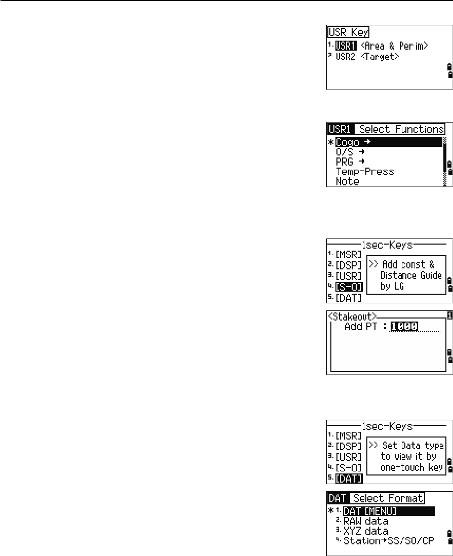
Total Station Nivo Series Instruction Manual 133
Menu Key 5
There are two [USR] keys. The function that is assigned
to each key appears beside the key name.
–To change the settings for the [USR1] key,
press [1] or select USR1.
–To change the settings for the [USR2] key,
press [2] or select USR2.
In the Select Functions screen, the asterisk (*)
indicates the function that is currently assigned to the
key.
To highlight a function, use [^] or [v]. To assign that
function to the selected [USR] key, press [ENT].
[S-O] key settings
To enter the Stakeout settings screen, press [4] or select
[S-O] in the 1sec-Keys menu.
There are two Stakeout settings. For more information,
see Stakeout, page 111.
[DAT] key settings
1. To change the settings for the [DAT] key, press [5]
or select [DAT] in the 1sec-Keys menu.
The asterisk (*) indicates the currently selected
view format.
2. To move the cursor, use [^] or [v].
3. To change the format displayed by [DAT], press
[ENT].
5 Menu Key
134 Total Station Nivo Series Instruction Manual
Calibration
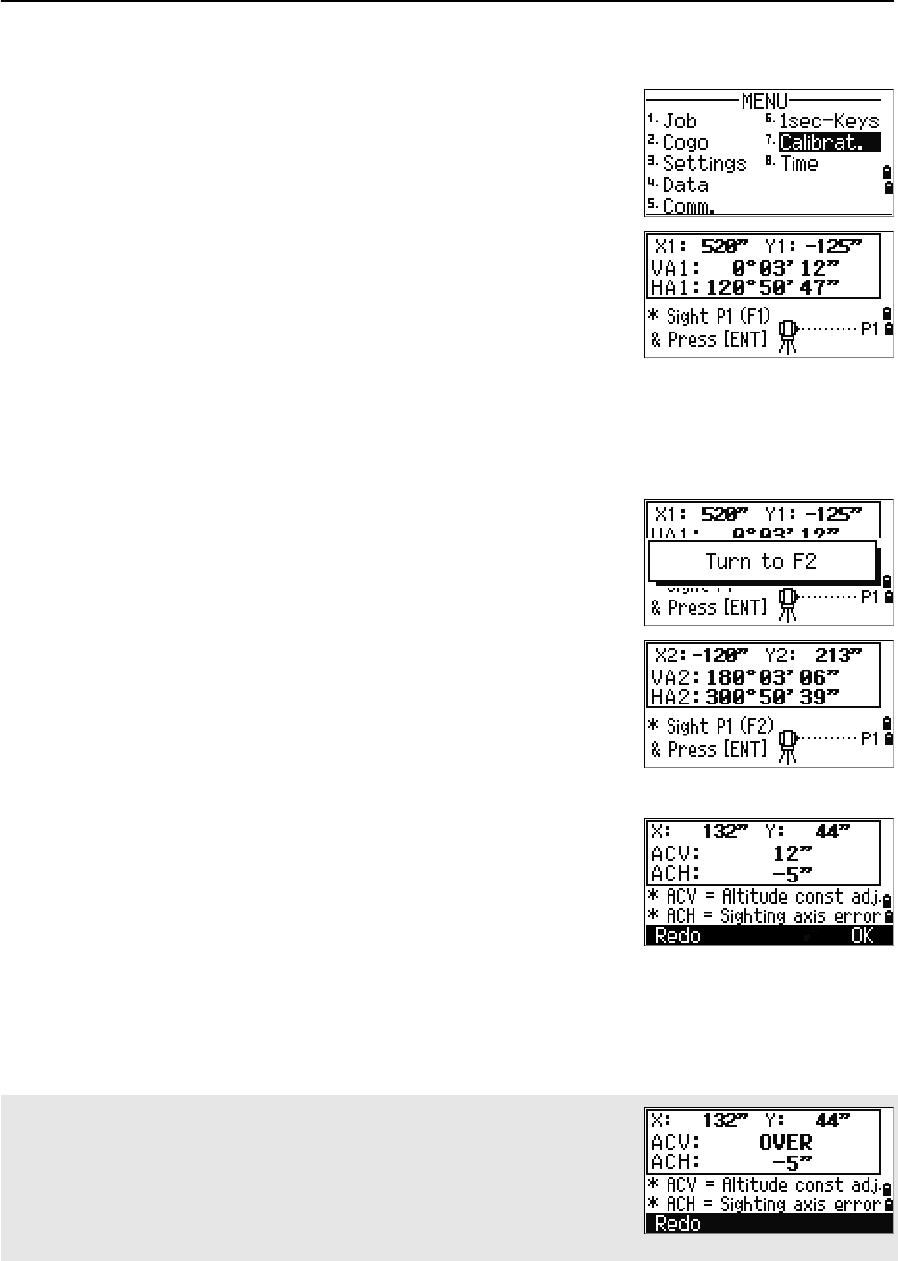
Use the Calibration screen to calibrate the instrument.
To open the Calibration screen, press [7] or select
Calibrat. on the MENU screen.
For more information, see Adjusting, page 138.
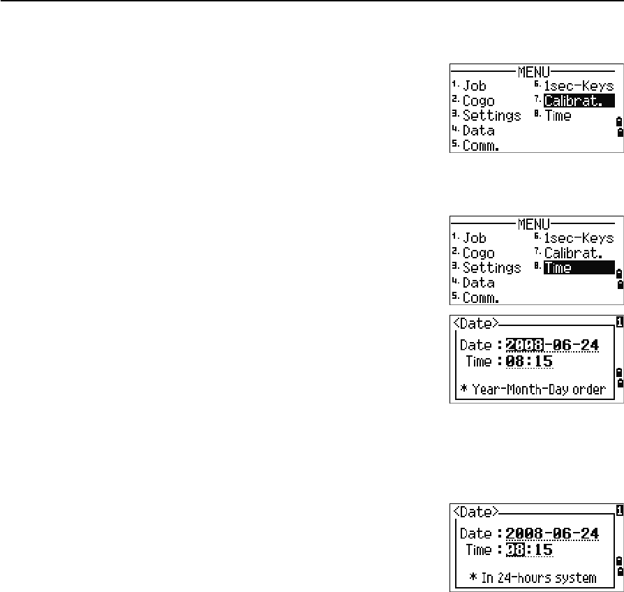
Time
Use the Date & Time screen to set the current date and
time.
1. To open the Date & Time screen, press [8] or
select Time on the MENU screen.
The current date and time settings are displayed.
2. Enter the date in Year-Month-Day format. For
example, to change the date to June 18, 2008,
press
[2] [0] [0] [8] [ENT] [6] [ENT] [1] [8] [ENT].
If the highlighted part of the field (for example, the year) is already correct, you
can just press [ENT] to use the current value. For example, if the date is already
set to June 24, 2008, and you want to change the date to June 18, 2008, press
[ENT] [ENT] [1] [8] [ENT].
3. To move to the Time field, press [ENT] in the Date
field.
4. Enter the time in 24-hour format. For example,
to set the time to 4:35 PM, press
[1] [6] [ENT] [3] [5] [ENT].
5. Do one of the following:
–To finish setting the date and time, press [ENT] in the Minutes field.
–To cancel the input, press [ESC].

CHAPTER
6
Total Station Nivo Series Instruction Manual 135
Checking and Adjustment 6
In this chapter:
QAdjusting the Electronic Level
QChecking and Adjusting the Circular Level
QChecking and Adjusting the Optical/Laser Plummet
QZero Point Errors of Vertical Scale and Horizontal Angle Corrections
QChecking the Instrument Constant
QChecking the Laser Pointer
6 Checking and Adjustment
136 Total Station Nivo Series Instruction Manual
Adjusting the Electronic Level
Adjustment of the electronic level is done by Zero point errors of vertical scale and
horizontal angle corrections. For detailed instruction, please see page 137.
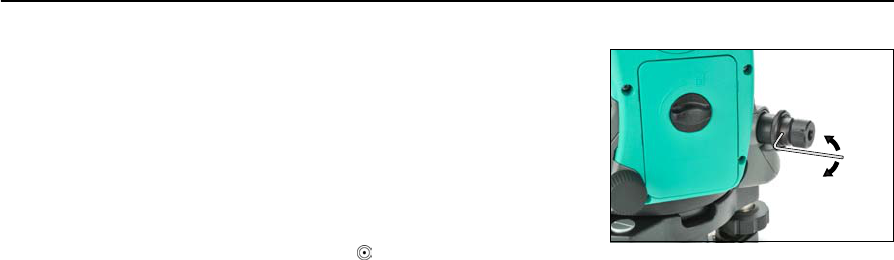
Checking and Adjusting the Circular Level
Once you have checked and adjusted the electronic
level, check the circular level.
If the bubble is not in the center of the level, use the
adjusting pin to rotate the three adjustment screws
of either circular level on the instrument main body
or tribrach until the bubble is centered.
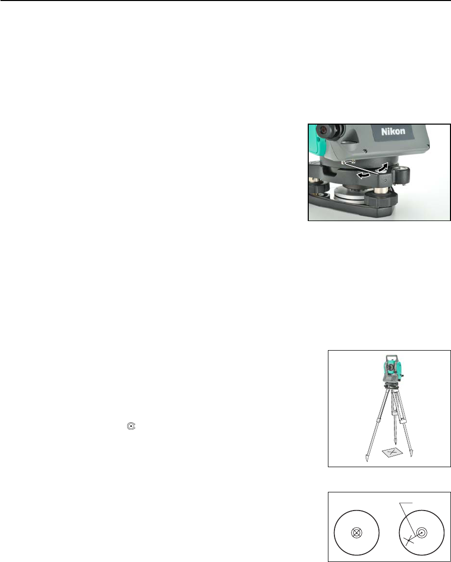
Checking and Adjusting the Optical/Laser Plummet
The optical axis of the plummet must be aligned with the vertical axis of the
instrument.
To check and adjust the optical/laser plummet:
1. Place the instrument on the tripod. You do not have to level the instrument.
2. Place a thick sheet of paper marked with an X on
the ground below the instrument.
While you are looking through the optical
plummet, adjust the leveling screws until the
image of the X is in the center of the reticle
mark .
For laser plummet, adjust the laser pointer to the
X.
3. Rotate the alidade 180°.
If the marked image is in the same position in the
center of the reticle mark, no adjustment is
required
For laser plummet, if the laser pointer is on the X,
no adjustment is required.
P
Total Station Nivo Series Instruction Manual 137
Checking and Adjustment 6
4. If the image or laser pointer is not in the same
position, adjust the optical or laser plummet:
a. Use the supplied hexagonal wrench to
turn the adjustment screws until the
image of the X is in Position P. Position
P is the center point of the line
connecting the X and the center of the
reticle mark .
b. Repeat from Step 2.
For laser plummet adjustment, a cap needs to be removed.
Zero Point Errors of Vertical Scale and Horizontal Angle Corrections
Checking
1. Set up the instrument on the tripod.
2. Follow the leveling procedures described in Leveling, page 15.
3. Flip the telescope to the Face-1 position.
4. Sight a target that is within 45° of the horizontal plane.
5. Read the vertical angle from the VA1 field in the Basic Measurement Screen
(BMS).
6. Rotate the instrument 180° and flip the telescope to the Face-2 position.
7. Read the vertical angle from the VA2 field.
8. Add the two vertical angles together, VA1 + VA2.
–No adjustment is required if the zero reference for vertical angles (VA
zero setting) is set to Zenith, and VA1 + VA2 equals 360°.
–No adjustment is required if the zero reference for vertical angles (VA
zero setting) is set to Horizon, and VA1 + VA2 is either 180° or 540°.
–An adjustment is required if VA1 + VA2 is not one of the values listed
above.
Note – The difference between the vertical angle reading the relevant angle (either
360° for Zenith, or 180° or 540° for Horizon) is called the altitude constant.
6 Checking and Adjustment
138 Total Station Nivo Series Instruction Manual
Adjusting
To enter the calibration screen, press [MENU] and [7].
1. The Nivo series has two-axis level
compensation.Take an F1 measurement to a
target on the horizon. Press [ENT].
The vertical angle is shown in the
V0 dir= Horiz setting.
When you have taken the measurement, the
message on the bottom line changes from DO
NOT TOUCH! to Turn to F2.
2. Take an F2 measurement to the same target.
Press [ENT].
When the observation on F2 is completed, four
parameters are displayed.
3. Do one of the following:
–To return to the first observation screen, press [ESC] or the Redo softkey.
–To set parameters on the instrument, press [ENT] or the OK softkey.
VA1 Face-1 vertical angle (tilt-off value)
HA1 Face-1 horizontal angle (tilt-off value)
X1 Face-1 X axis tilt value
Y1 Face-1 Y axis tilt value
VA2 Face-2 vertical angle (tilt-off value)
HA2 Face-2 horizontal angle (tilt-off value)
X2 Face-2 X axis tilt value
Y2 Face-2 Y axis tilt value
IIf ACV, ACH, X, or Y is out of range, OVER appears. Press any key to return
to the first observation screen.
Total Station Nivo Series Instruction Manual 139
Checking and Adjustment 6
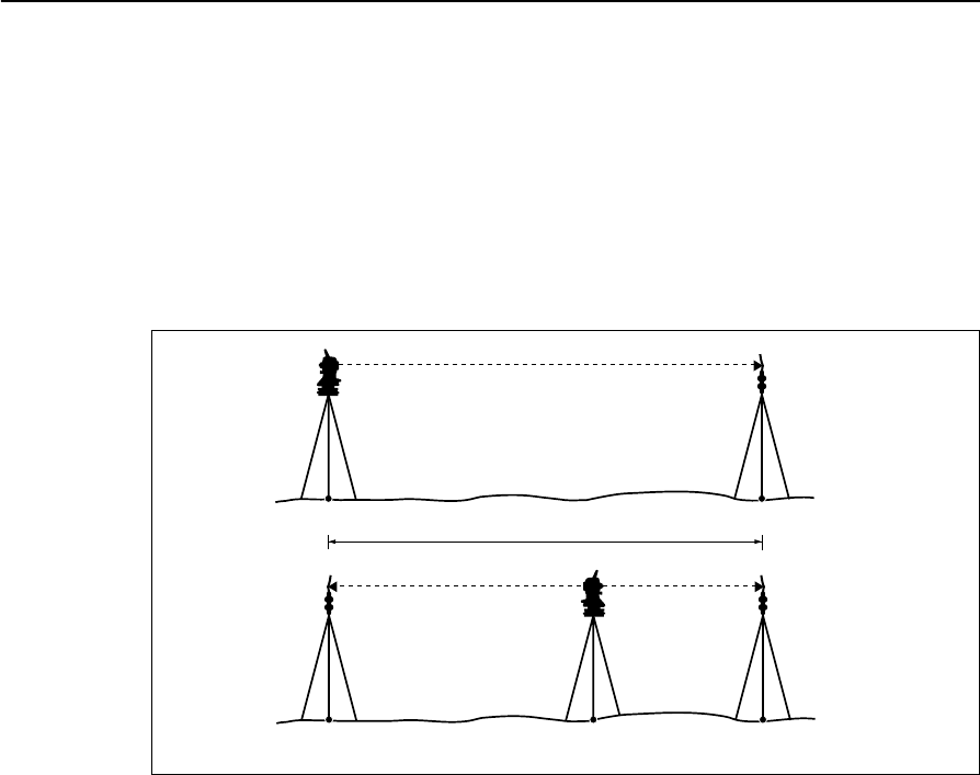
Checking the Instrument Constant
The instrument constant is a numerical value used to automatically correct for the
displacement between the mechanical and electrical centers when measuring
distances. The instrument constant is set by the manufacturer before the instrument is
shipped. However, to ensure the highest operational accuracy, we recommend that
you check the instrument constant several times a year.
To check the instrument constant, you can either compare a correctly measured base
line with the distance measured by the EDM, or follow the procedure below.
To check the instrument constant:
1. Set up the instrument at Point P, in as flat an area as possible.
2. Set up a reflector prism at Point Q, 100 m away from Point P. Make sure that
you take the prism constant into account.
3. Measure the distance between Point P and Point Q (PQ).
4. Install a reflector prism on the tripod at Point P.
5. Set up another tripod at Point R, on the line between Point P and Point Q.
6. Transfer the Nivo series instrument to the tripod at Point R.
7. Measure the distance from Point R to Point P (RP), and from Point R to
Point Q (RQ).
8. Calculate the difference between the value of PQ and the value of RP + RQ.
9. Move the Nivo series instrument to other points on the line between Point P
and Point Q.
10. Repeat Step 5 through Step 9 ten times or so.
11. Calculate the average of all the differences.
The error range is within 3 mm. If the error is out of range, contact your dealer.
About 100 m
PQ
PRQ

6 Checking and Adjustment
140 Total Station Nivo Series Instruction Manual
Checking the Laser Pointer
The Nivo series total station uses a red laser beam to a laser pointer. The laser pointer
is coaxial with the line of sight of the telescope. If the instrument is well adjusted, the
red laser pointer coincides with the line of sight. External influences such as shock or
large temperature fluctuations can displace the red laser pointer relative to the line of
sight.

CHAPTER
7
Total Station Nivo Series Instruction Manual 141
Specifications 7
In this chapter:
QMain Body
QStandard Components
QExternal Device Connector

7 Specifications
142 Total Station Nivo Series Instruction Manual
Main Body
Telescope
Measurement range
Distances shorter than 1.5 m (4.92 ft) cannot be measured with this EDM.
•The target should not receive direct sunlight.
•“Reference target” refers to a white, highly reflective material. (KGC90%)
•The maximum measurement range is 500 m in the reflectorless mode.
Distance precision
Tube length 125 mm (4.91 in.)
Magnification 30 X
Effective diameter of objective 45 mm (1.77 in.)
EDM 50 mm (1.97 in.)
Image Erect
Field of view 1°20'
2.3 m at 100 m (2.3 ft at 100 ft)
Resolving power 3.0''
Focusing distance 1.5 m to infinity (4.92 ft to infinity)
Measurement range with no haze, visibility over 40 km (25 miles))
Prism mode
Reflector sheet (5 cm x 5 cm) 300 m (984 ft)
Standard prism (1P) 5,000 m (16,400 ft)
Reflectorless mode
Reference target 300 m (984 ft)
Precise mode
Prism ± (3 + 2 ppm × D) mm (–10 °C to +40 °C)
± (3 + 3 ppm × D) mm
(–20 °C to –10 °C, +40 °C to +50 °C)
Reflectorless ± (3 + 2 ppm × D) mm (–10 °C to +40 °C)
± (3 + 3 ppm × D) mm
(–20 °C to –10 °C, +40 °C to +50 °C)
Normal mode
Prism ± (10 + 5 ppm × D) mm
Reflectorless ± (10 + 5 ppm × D) mm

Total Station Nivo Series Instruction Manual 143
Specifications 7
Measurement intervals
Measurement intervals may vary with the measuring distance or weather conditions.
For the initial measurement, it may take few more seconds.
Angle measurement
Tilt sensor
Tangent screw
Tribrach
Precise mode
Prism 1.5 sec.
Reflectorless 1.8 sec.
Normal mode
Prism 0.8 sec.
Reflectorless 1.0 sec.
Prism offset correction –999 mm to +999 mm (1 mm step)
Reading system Absolute encoder
Nivo3.M Diametrical reading on HA
Single reading on VA
Nivo5.M Single reading on HA/VA
Minimum display increment
360° 1''/5''/10"
400G 0.2 mgon/1 mgon/2 mgon
MIL6400 0.005 MIL/0.02 MIL/0.05 MIL
DIN18723 accuracy Nivo3.M: 3" / 1.0 mgon
Nvo5.M: 5"/1.5 mgon
Method Liquid-electric detection (Dual axis)
Compensation range ±3'
Type Friction clutch endless fine motion
Type Detachable

7 Specifications
144 Total Station Nivo Series Instruction Manual
Level
Optical plummet
Optional laser plummet
Display and keypad
Connections in the base of instrument
Electronic level Displayed on the LCD
Circular level vial Sensitivity 10'/2 mm
Image Erect
Magnification 3×
Field of view 5°
Focusing range 0.5 m (1.6 ft) to infinity
Wave length 635 nm
Laser class Class 2
Focusing range ∞
Laser diameter Approx. 2 mm
Display type Graphical LCD
Resolution 128 × 64
Display illumination Backlight
Keys 25
Communications
Type RS-232C
Maximum baud rate 38400 bps asynchronous
External power supply
input voltage 4.5 V to 5.2 V DC

Total Station Nivo Series Instruction Manual 145
Specifications 7
Battery pack
Tested at 25 °C (nominal temperature). Operation times may vary depending on the
condition and deterioration of the battery.
Environmental performance
Dimensions
Weight
Environmental protection
Output voltage 3.8 V DC rechargeable
Continuous operation time
Continuous distance/angle
measurement
10 hours
Distance/angle measurement
every 30 seconds
16 hours
Continuous angle measurement 30 hours
Operating temperature range –20 °C through +50 °C (–4 °F through +122 °F)
Storage temperature range –25 °C through +60 °C (–13 °F through +140 °F)
Main unit 149 mm W x 145 mm D x 306 mm H
Carrying case 435 mm W x 206 mm D x 297 mm H
Main unit w/o battery 3.5 kg (7.95 lbs), approx.
Battery 0.1 kg (0.22 lbs), approx.
Carrying case 2.4 kg (5.28 lbs), approx.
Charger and AC adapter 0.4 kg (0.99 lbs), approx.
Watertight/dust-proof protection IP66

7 Specifications
146 Total Station Nivo Series Instruction Manual
Standard Components
•Instrument main body
•Battery pack (X 2)
•Universal charger, power cord, and adapters
•Adjustment pin, Allen wrench
•Objective lens cap
•Vinyl cover
•Total Station Nivo Series Instruction Manual (this document)
•Carrying case
•Shoulder strap (X 2)
External Device Connector
This connector can be used to connect to an external power source or to communicate
with an external device.
Before using the external device connector, make sure that the external device meets
the specifications below.
CCAUTION – Except for the connection shown in Figure 8.1on page 150, use of this connector
is at your own risk.
CCAUTION – Use only the male connectors specified above. Using other connectors will
damage the instrument.
Input voltage 4.5 V to 5.2 V DC
System RS-232C
Signal level ±9 V standard
Maximum baud rate 38400 bps asynchronous
Compatible male connector Hirose HR10A-7P-6P or HR10-7P-6P
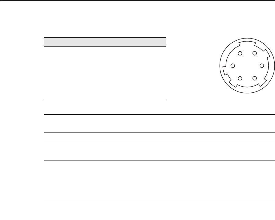
Total Station Nivo Series Instruction Manual 147
Specifications 7
The external device connector is a Hirose HR 10A-7R-6S female connector. The
pinouts for connecting it to an external device connector are shown below:
CCAUTION – Use only the pin connections shown above. Using other connections will damage
the instrument.
CCAUTION – The Nivo series total station has different pin assignment from other models of
Nikon total station.
To connect to an external power source, supply power to Pin 4 (power terminal) and
Pin 5 (ground terminal) on the instrument. The instrument will use the external power
source even if the internal battery packs are attached.
CCAUTION – Make sure that the power supplied is within the rated input range (4.5 V to 5.2 V
DC, 1 A maximum). Power supplied outside this range will damage the instrument.
To communicate with an external device, connect the RS-232C signal from the
external device to Pin 1 (input terminal) and to Pin 2 (output terminal) on the
instrument.
Cap the data output/external power input connector securely while not in use. The
instrument is not watertight if the cap is not attached or not attached securely, and
when the data output/external power input connector is in use.
The instrument can be damaged by static electricity from the human body discharged
through the data output/external power input connector. Before handling the
instrument, touch any other conductive material once to remove static electricity.
Pin Signal Description
1 RXD Receive data (Input)
2 TXD Send data (Output)
3 NC No connection
4VPower
5 GND Ground
6 NC No connection
HRS
16
25
34

7 Specifications
148 Total Station Nivo Series Instruction Manual

CHAPTER
8
Total Station Nivo Series Instruction Manual 149
System Diagrams 8
In this chapter:
QSystem Components
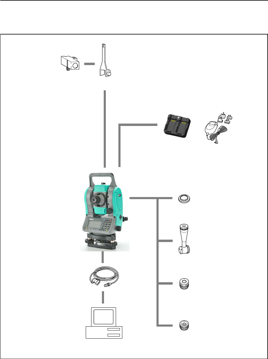
8 System Diagrams
150 Total Station Nivo Series Instruction Manual
System Components
Figure 8.1 Measurement side
Tubular
Compass
Tubular compass
attachment
Nivo series
Connecting cable
Personal computer
Diagonal eyepiece
Battery charger
Low-power
eyepiece
High-power
eyepiece
Solar filter
AC adapter and
plug adapter
(9 pin, USB)
Total Station Nivo Series Instruction Manual 151
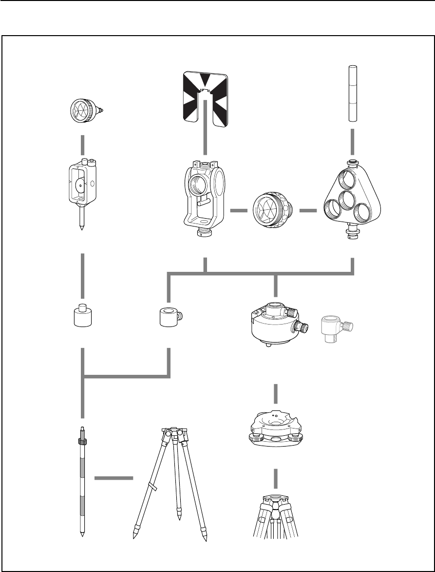
System Diagrams 8
Figure 8.2 Prism reflector side
Note – Nivo series must be used with the Tribrach W30 or W30b.
Mini prism C
Mini prism
holder
Mini prism
adapter
Telescopic
prism pole
Coaxial target plate
for single prism
Tiltable single
prism holder
Prism adapter
Tripod for telescopic prism pole
Standard round
single prism C
Ta r ge t p o l e
Triple prism
holder
Tribrach adapter 15
Nikon tripod
Tribrach W30/W30b
Height adjustment
adapter is not used.

8 System Diagrams
152 Total Station Nivo Series Instruction Manual

CHAPTER
9
Total Station Nivo Series Instruction Manual 153
Communications 9
In this chapter:
QUploading Coordinate Data
QUploading Point Lists and Code Lists
QDownloading Data
9 Communications
154 Total Station Nivo Series Instruction Manual
Uploading Coordinate Data
Settings
To configure the transmission speed and other settings,
go to MENU > Settings > Comm. For more
information, see Communications, page 111.
Record format
You can upload coordinate records in the following formats:
PT ,X ,Y ,Z ,CD
PTXYZCD
PT ,X ,Y ,Z
PTXYZ
PT ,X ,Y ,,CD
PTXYCD
PT ,X ,Y ,,
PT , X , Y ,
PT ,,,Z ,CD
PT ,,,Z
Total Station Nivo Series Instruction Manual 155
Communications 9
The record formats shown above use the following codes:
Data example
20100,6606.165,1639.383,30.762,RKBSS
20104,1165611.6800,116401.4200,00032.8080
20105 5967.677 1102.343 34.353 MANHOLE
20106 4567.889 2340.665 33.444 PT1
20107 5967.677 1102.343 34.353
20109,4657.778,2335.667,,PT2
20111,4657.778,2335.667
20113 4657.778 2335.667
20115,,,34.353,MANHOLE
20117,,,33.444
Code Description Length
PT Point number Up to 20 digits
X Actual X coordinate Variable length
Y Actual Y coordinate Variable length
Z Actual Z coordinate Variable length
CD Feature code Up to 16 characters
9 Communications
156 Total Station Nivo Series Instruction Manual
Uploading Point Lists and Code Lists
Settings
To configure the transmission speed and other settings,
go to MENU > Settings > Comm. For more
information, see Communications, page 111.
File format
PT lists and code lists use the same record format. Use the filenames POINT.LST for
a PT list, and CODE.LST for a code list.
Figure 9.1 Record format for PT lists and code lists
DEFAULT
{
String1 , Code1
Layer2
{
String2-1, Code2-1
String2-2, Code2-2
}
Layer3
{
Layer 3-1
{
String3-1-1, Code3-1-1
String3-1-2, Code3-1-2
}
String3-2, Code3-2
String3-3, Code3-3
}
String4, Code4
String5, Code5
String6, Code6
String7, Code7
}
The first line of the file must
contain the text “DEFAULT” in
capital letters.
Curly brackets { } group items
together under the preceding
line.
For example, Layer 3-1
contains String 3-1-1 and
String 3-1-2.
Layer 3 contains the five
items from Layer 3-1 to
String 3-3.
“String” represents characters
that are displayed on the
screen. “Code” represents
characters that are stored in
the database.

Total Station Nivo Series Instruction Manual 157
Communications 9
Data example
DEFAULT
{
“STRUCTURES”
{
“TREE”, “S0001”
“FENCE”, “S0002”
“MAIL BOX”, “S0003”
“FLOWER BED”, “S0004”
}
“ROADS”
{
“MANHOLE”, “R0001”
“CENTER LINE”
{
“WHITE”, “R002-W”
“YELLOW”, “R002-Y”
}
“SIDEWALK”, “R0003”
“CROSSING”, “R0004”
“BRIDGE”, “R0005”
“SIGNAL”, “R0006”
“HIGHWAY STAR”, “R0007”
}
“RAILWAY”
{
“CROSSING”, “RW001”
“STATION”, “RW002”
“SIGNAL”, “RW003”
“BRIDGE”, “RW004”
“TUNNEL”, “RW005”
}
}
9 Communications
158 Total Station Nivo Series Instruction Manual
Downloading Data
Settings
To configure the transmission speed and other settings,
go to MENU > Settings > Comm. For more
information, see Communications, page 111.
Nikon raw record formats
Coordinate records
Station records
type , pt , (pt id) , northing , easting , elevation , code
type One of the following codes:
UP Uploaded point
MP Manually input point
CC Calculated coordinate
RE Resection point
pt Point number
(pt id) (Point ID)
northing Northing of the coordinate
easting Easting of the coordinate
elevation Elevation of the coordinate
code Feature code
ST , stnpt , (stnid) , bspt , (bs id) , hi , bsazim , bsha
ST Station record identifier (fixed text)
stnpt Station point number
(stn id) (Station ID)
bspt Backsight point number
(bs id) (Backsight ID)
hi Height of instrument
bsazim Backsight azimuth
bsha Backsight horizontal angle
Total Station Nivo Series Instruction Manual 159
Communications 9
Control point records
Sideshot records
Stakeout records
CP ,pt,(pt id),ht,sd,ha,va,time,code
CP Control point record identifier (fixed text)
pt Point number
(pt id) (Point ID)
ht Height of target
sd Slope distance
ha Horizontal angle
va Vertical angle
time 24-hour time stamp
code Feature code
SS ,pt,ht,sd,ha,va,time,code
SS Sideshot record identifier (fixed text)
pt Point number
ht Height of target
sd Slope distance
ha Horizontal angle
va Vertical angle
time 24-hour time stamp
code Feature code
SO ,pt,(sopt),ht,sd,ha,va,time,
SO Stakeout record identifier (fixed text)
pt Recorded point number
(sopt) (Original number of point staked)
ht Height of target
sd Slope distance
ha Horizontal angle
va Vertical angle
time 24-hour time stamp
9 Communications
160 Total Station Nivo Series Instruction Manual
F1 records
Comment/note records
face,pt,ht,sd,ha,va,time
face One of the following:
F1 Shot taken using Face-1 (fixed text)
Shot taken using Face-1 for Station setup (fixed text)
pt Point number
ht Height of target
sd Slope distance
ha Horizontal angle
va Vertical angle
time 24-hour time stamp
CO ,text
CO Comment record identifier (fixed text)
text Comment text
Total Station Nivo Series Instruction Manual 161
Communications 9
SDR2x and SDR33 record formats
Header record
Instrument record
00NM ver 0000 datetime ang dist press temp coor 1
1–4 00NM Header record identifier (fixed text)
5–20 ver SDR download version. One of the following:
SDR20V03-05 SDR2x
SDR33V04-01 SDR33
21–24 0000 Not used
25–40 datetime Download date and time (in hours and minutes)
41 ang Angle units. One of the following:
1Degrees
2Gons
4Mils
42 dist Distance units. One of the following:
1Meters
2Feet
43 press Pressure units. One of the following:
1mm Hg
2In. Hg
3hPa
44 temp Temperature units. One of the following:
1Celsius
2Fahrenheit
45 coor Coordinate order. One of the following:
1NEZ
2ENZ
46 1Not used
01KI1 instr serNo Instr serNo 1zero VA 0.000 0.000 0.000
1–5 01KI1 Instrument record identifier (fixed text)
6–21,
28–43
instr Instrument make and model
22–27,
44–49
serNo Instrument serial number
50 1Not used
51 zero VA The reference point for vertical angles. One of the
following:
1Zenith
2Horizon
52–61,
62–71,
72–81,
0.000
0.000
0.000
Not used
Not used
Not used
9 Communications
162 Total Station Nivo Series Instruction Manual
Station details record
Target details record
Backsight bearing details record
02KI stnpt northing easting elevation hi desc
1–4 02KI Station details record identifier (fixed text)
5–8 (2x),
5–20 (33)
stnpt Station point number
9–18 (2x),
21–36 (33)
northing Northing of station
19–28 (2x),
37–52 (33)
easting Easting of station
29–38 (2x),
53–68 (33)
elevation Elevation of station
39–48 (2x),
69–84 (33)
hi Height of instrument
49–64 (2x),
85–100 (33)
desc Station description
03NM ht
1–4 03NM Target details record identifier (fixed text)
5–14 (2x),
5–20 (33)
ht Height of target
07KIstnpt bspt bsazim ha
1–4 07KI Backsight bearing details record identifier
(fixed text)
5–8 (2x),
5–20 (33)
stnpt Station point number
9–12 (2x),
21–36 (33)
bspt Backsight point number
13–22 (2x),
37–52 (33)
bsazim Backsight azimuth
23–32 (2x),
53–68 (33)
ha Horizontal angle
Total Station Nivo Series Instruction Manual 163
Communications 9
Coordinates record
Observation record
08KI pt northing easting elevation desc
1–4 08KI Coordinates record identifier (fixed text)
5–8 (2x),
5–20 (33)
pt Point number
9–18 (2x),
21–36 (33)
northing Northing of the coordinate
19–28 (2x),
37–52 (33)
easting Easting of the coordinate
29–38 (2x),
53–68 (33)
elevation Elevation of the coordinate
39–54 (2x),
69–84 (33)
desc Feature code
09MC stnpt pt sd va ha desc
1–4 09MC Observation record identifier (fixed text)
5–8 (2x),
5–20 (33)
stnpt Station point number
9–12 (2x),
21–36 (33)
pt Observed point number
13–22 (2x),
37–52 (33)
sd Slope distance
23–32 (2x),
53–68 (33)
va Vertical angle
33–42 (2x),
69–84 (33)
ha Horizontal angle
43–58 (2x),
85–100 (33)
desc Feature code
9 Communications
164 Total Station Nivo Series Instruction Manual
Job identifier record
Note record
10NM jobid 1incZ T&Pcorr C&Rcorr refcon sealev
1–4 10NM Job identifier record ID (fixed text)
5–8 (2x),
5–20 (33)
jobid Job name/title
Note – The following fields occur only in SDR33
format.
21 1Point ID length option
22 incZ 2D or 3D coordinates. One of the following:
12D
23D
23 T&Pcorr Atmospheric correction. One of the following:
1Off
2On
24 C&Rcorr Curvature and refraction correction. One of the
following:
1Off
2On
25 refcon Refraction constant. One of the following:
10.132
20.200
26 sealev Sea level correction. One of the following:
1Off
2On
13NM note
1–4 13NM Note record ID (fixed text)
5–64 note Note text

Total Station Nivo Series Instruction Manual 165
Communications 9
Data examples
Nikon raw data format
CO,Nikon RAW data format V2.00
CO,EXAMPLE5
CO,Description: SAMPLE DATA OF DOWNLOAD
CO,Client:
CO,Comments:
CO,Downloaded 22-JUL-2008 18:56:10
CO,Software: Pre-installed version: 1.0.0.1
CO,Instrument: Nivo 5.M
CO,Dist Units: Metres
CO,Angle Units: DDDMMSS
CO,Zero azimuth: North
CO,Zero VA: Zenith
CO,Coord Order: NEZ
CO,HA Raw data: Azimuth
CO,Tilt Correction: VA:ON HA:ON
CO, EXAMPLE5 <JOB> Created 22-JUL-2008 07:09:21
CO,S/N:213705
MP,1,,100.000,200.000,10.000,
CO,Temp:20C Press:760mmHg Prism:0 22-JUL-2008 07:11:34
ST,1,,,,1.400,55.4500,55.4500
F1,,,,0.0000,90.0000,8:27:58
SS,3,1.200,330.706,326.027,20.320,07:13:46,SIGN
SS,4,1.250,379.193,300.847,29.084,07:14:24,TREE
SS,5,1.218,363.344,328.032,30.105,07:14:57,TREE R
SO,1003,,1.240,331.220,326.783,19.998,07:18:17,
Nikon coordinate data format
1,100.0000,200.0000,10.0000,
2,200.0000,300.0000,20.0000,
3,116.9239,216.9140,11.8425,TRAIN PLATFORM
4,126.6967,206.2596,11.2539,RAMP
11,100.0045,199.9958,10,0000,
13,116.9203,216.9113,11.7157,
14,126.6955,206.2579,10.9908,
21,100.0103,199.9958,10.0000,
31,100.0013,200.0005,10.0000,
41,100.0224,200.0331,9.9000,
43,116.9263,216,9165,11.8016,CURB
44,126.7042,206.2871,10.8193,DITCH
45,116.9266,216.9160,11.8028,
46,126.7046,206.2845,10.8213,CP POINT

9 Communications
166 Total Station Nivo Series Instruction Manual
SDR2x raw data format
00NMSDR20V03-05 000023-Jul-2008 18:39:111211
10NMEXAMPLE6
01KI1 Nikon Nivo 5.M 000000 Nikon Nivo 5.M 00000012 0.000 0.000 0.000
13NMDownloaded 23-Jul-2008 18:39:22
13NMSftware: Pre-install version: 1.0.0.1
13NMInstrument: Nikon Nivo 5.M
13NMDist Units: Metres
13NMAngle Units: Degrees
13NMZero azimuth: North
13NMZero VA: Horizon
13NMCoord Order: NEZ
13NMClient:
13NMDescription:
13NMTilt Correction: VA:ON HA:ON
13NM EXAMPLE6 <JOB> Created 23-Jul-2008 07:09:21
08KI0001100.000 200.000 10.000
08KI0002200.000 300.000 20.000
02KI0001100.000 200.000 10.000 0.100
07KI0001000245.0000 0.0000
13F100000002<null> <null> 0.0000
13F200000002<null> <null> 179.9639
13NMBS Check HA:359.3525 Reset to HA: 0.0000 07:21:41
13F10000000323.990 4.1694 0.0000
13F20000000323.990 175.8403 180.0028
03NM0.000
13F10001000323.990 4.1653 359.9833 MAIN PLATFORM
13F10001000427.445 2.4097 328.1958 RAMP
13NMStart of 2-Pt Resection
13F10000000427.445 2.4097 0.0000
13F10000000323.991 4.1542 31.8042
13F10000000427.430 1.8583 121.4306
13F10000000323.976 3.8625 153.2306
08KI0011100.005 199.996 10.000
02KI0011100.005 199.996 10.000 0.100
07KI0011000344.9980 0.0000

Total Station Nivo Series Instruction Manual 167
Communications 9
SDR2x coordinate data format
00NMSDR20V03-05 000023-Jul-2008 18:40:111211
10NMEXAMPLE6
01KI1 Nikon Nivo 5.M 000000 Nikon Nivo 5.M 00000012 0.000 0.000 0.000
13NM 080926-2 <JOB> Downloaded 08-Oct-2008 18:40:06
13NMSftware: Pre-install version: 1.0.0.1
13NMInstrument: Nikon Nivo 5.M
13NMDist Units: Metres
13NMAngle Units: Deqrees
13NMZero azimuth: North
13NMZero VA: Horizon
13NMProjection correction: OFF
13NMC&R correction: OFF
13NMSea level correction: OFF
13NMCoord Order: NEZ
13NMClient:
13NMDescription:
13NMTilt Correction: VA:OFF HA:OFF
13NM EXAMPLE6 <JOB> Created 23-Jul-2008 07:09:21
13NMPrism constant: 0
08KI0001100.000 200.000 10.000
08KI0002200.000 300.000 20.000
13NMBacksight Check to Pt:2 HA:359.3525 07:21:39
13NMBacksight Pt:2 Reset to HA: 0.0000 07:21:41
08KI0003116.924 216.914 11.843 MAIN PLTFORM
08KI0004126.697 206.260 11.254 RAMP
13NMStart of 2-Pt Resection
08KI0011100.005 199.996 10.000

9 Communications
168 Total Station Nivo Series Instruction Manual

CHAPTER
10
Total Station Nivo Series Instruction Manual 169
Error Messages 10
In this chapter:
QCogo
QCommunications
QData
QJob Manager
QPrograms
QRecording Data
QSearching
QSettings
QStakeout
QStation Setup
QSystem Error

10 Error Messages
170 Total Station Nivo Series Instruction Manual
Cogo
NO Result 100.1
The system was unable to calculate an area because points were not entered in the
correct order.
Press any key to return to the Cogo menu. Then enter the points in the correct order.
Same Coordinate 100.2
The point or coordinate that you entered is identical to the previous input point.
Press any key to return to the point input screen. Then use a different point.
XY-coordinate is required 100.3
The input point does not have XY (NE) coordinates.
Press any key to return to the point input screen. Then enter a point that has X and
Y coordinates.
Communications
If an error is detected during uploading of data, the Nivo instrument aborts the upload
process and displays one of the following messages.
Check Data 100.4
There are errors in the uploaded data. The uploaded data contains errors, such as an
alphabetic character in a coordinate field.
Press any key. Then check the specified line in the data.
DUPLICATE PT 100.5
The uploaded data contains a duplicate PT.
Press any key. Then check the specified point in the data.
BTip – If the existing point is a UP, CC, or MP record, and is not referred by ST or BS, then it will
be overwritten by the uploaded record. No error message appears.
PT MAX20 chars 100.6
The uploaded data contains a PT with a name or number that is longer than 20 digits.
Press any key. Then check the specified line in the data.
XYZ OVERRANGE 100.7
The uploaded data contains a coordinate that is longer than 13 digits.
Press any key. Then check the specified line in the data.

Total Station Nivo Series Instruction Manual 171
Error Messages 10
Data
Can't Edit Current ST 100.8
You have tried to edit the current ST.
Note – You cannot edit the current ST. However, old ST records can be edited. No
recalculation can be performed on the instrument.
Press any key to return to the code/layer name input screen.
Can't Edit ST/BS refer to this PT 100.9
You have tried to edit a coordinate that the current ST or BS refers to. You cannot
change a coordinate if the current ST or BS refers to it.
Press any key to return to the Data view screen.
Can't Edit XYZ from measurement 100.10
You have tried to change the coordinates of an SO, SS, or CP record. You cannot
change the coordinates of an SO, SS, or CP record.
Press any key to return to the previous screen.
DELETE Stn-XYZ 100.11
You have tried to delete a coordinate record that the current ST or BS refers to. You
must confirm that you want to delete a coordinate record that the current ST or BS
refers to.
To ... Press ...
delete XYZ the DEL softkey
return to the previous screen without deleting XYZ [ESC] or the Abrt softkey

10 Error Messages
172 Total Station Nivo Series Instruction Manual
Job Manager
Cannot Assign 100.12
You have tried to set the current job as the control file.
Press any key to return to the previous screen. Then select a different job.
Can't Create 100.13
There is no space available to create a job or record a point.
Press any key to return to the Job Manager. Then use the DEL softkey to delete old
jobs.
Existing Job 100.14
You have entered an existing job name for a new job.
Press any key and then change the name for the new job.
MAX 32Jobs 100.15
You are trying to create a new job when the maximum number of jobs (32) is already
stored.
Press any key to return to the Job Manager. Then use the DEL softkey to delete old
jobs.
Programs
NO Stn Setup 100.16
You did not perform a station setup or BS check before entering the Programs
function.
BTip – Selecting Continue does not resume the last ST record. You should only use the
Continue option if you are sure that the previous ST coordinates and the current HA
orientation are correct. Otherwise, records in the Programs function may not be correct.
XY&Z coordinate are required 100.17
Three-dimensional coordinates are required in S-Plane function.
Press any key to return to the point input screen. Then enter a three-dimensional
point.
To ... Press ...
go to the Stn Setup menu [2] or select Stn Setup
return to the BMS [ESC]
go to the Programs menu [1] or select Continue

Total Station Nivo Series Instruction Manual 173
Error Messages 10
Recording Data
DATA FULL 100.18
The data storage is full.
Press any key to return to the Basic Measurement Screen (BMS). Then:
DUPLICATE PT 100.19
The input PT you are trying to record already exists in the current job. An existing
coordinate record cannot be overwritten by measured data.
Press any key to return to the point input screen. Change PT.
Duplicate PT 100.20
The input PT you are trying to record already exists in the current job as an SS, SO, or
CP record. An existing SS, SO, or CP record can be overwritten by measured data.
No Open Job 100.21
No job is open.
NO Stn Setup 100.22
There is no station record in the current job, or a station setup or BS check has not
been done since the program was rebooted.
To ... Go to ...
delete unnecessary data MENU > Data
delete jobs MENU > Job
To ... Press ...
return to the PT input screen [ESC] or the Abrt softkey
record RAW data and update XYZ data the XYZ softkey
record RAW data only the RAW softkey
To ... Press ...
open the job list, if there are existing jobs [1] or select Select job
create a new job [2] or select Create job
return to the previous screen [ESC]
To ... Press ...
continue recording [1] or select Continue. If there is already an ST record in the
job, the message CO, Use current orientation
appears.
go to the Stn Setup menu [2] or select STN Setup
return to the previous screen [ESC]

10 Error Messages
174 Total Station Nivo Series Instruction Manual
OVER RANGE 100.23
You are trying to record a coordinate with more than 13 digits
Press any key to return to the previous screen. Then check the current ST coordinate.
Searching
PT Not Found 100.24
There is no point that matches the criteria you entered.
Press any key to return to the point input screen.
This message may appear in any function where the PT/CD is input, such as Station
Setup or Stakeout.
Settings
Job Settings will be changed 100.25
You have changed one or more of the following job settings:
•VA zero or HA in the Angle screen (see Angle, page 108)
•Scale, T-P, Sea Lvl, or C&R in the Distance screen (see Distance, page 109)
•Coord or Az Zero in the Coordinates screen (see Coordinate, page 110)
•Angle, Dist, Temp, or Press in the Unit screen (see Unit, page 111)
Note – To record a point using the new settings, create a new job using the new
settings.
Stakeout
Input Error 100.26
The point name style used in the Fr field is not the same as the style used in the To
field. For example, the Fr field style is 1, and the To field style is A200.
Press any key to return to the Fr/To input screen. Then re-enter the point name, using
the same naming style in both fields.
To ... Press ...
discard the changes to the job settings [ESC] or the Abrt softkey. The current job
remains open.
close the current job and save the changes to
the job settings
[ENT] or the OK softkey
Total Station Nivo Series Instruction Manual 175
Error Messages 10
NO Stn Setup 100.27
You did not perform a station setup or BS check before entering the Stakeout
function.
BTip – Selecting Continue does not resume the last ST record. You should only use the
Continue option if you are sure that the previous ST coordinates and the current HA
orientation are correct. Otherwise, records in the Stakeout function may not be correct.
Station Setup
Calc ST Failed Need additional PT 100.28
Calculating ST failed in resection. This message may appear after you have deleted a
point the View shots screen.
Press any key to return to the PT input screen. Take another shot to calculate the ST
coordinate.
Same Coordinate 100.29
The input PT or coordinate is identical to the current station in STN/1:Known, or the
same coordinate or point name/number is found in Resection.
Press any key to return to the PT input screen. Then use a different PT.
Space LOW 100.30
There is not enough space to record a station when you start any of the Station Setup
functions.
XY-coordinate is required 100.31
The input point for ST/BS does not have N/E coordinates.
Press any key to return to the PT input screen. Then use a PT that has N/E
coordinates.
To... Press ...
go to the Stn Setup menu [2] or select Stn Setup
return to the Basic
Measurement Screen (BMS)
[ESC]
go to the Stakeout menu [1] or select Continue
To ... Press ...
return to the BMS press [ESC] or the Abrt softkey. Use the DEL
softkey in Job Manager to delete old jobs.
continue press [ENT] or the OK softkey. You may not be able to
record the whole process.

10 Error Messages
176 Total Station Nivo Series Instruction Manual
Z-coordinate is required 100.32
The input point for Benchmark does not have a Z coordinate.
Press any key to return to the PT input screen. Then use a PT that has a Z coordinate.
System Error
=SYSTEM ERROR= 100.33
The system has detected an internal error that is related to the lower-level system.
Press any key to turn the instrument off. The system will reboot when this error is
reported. If you still have more points to shoot in the site, turn the instrument on and
repeat the open a job and station setup procedures.
Data stored before this error will be kept safely in the Job file.
If the error appears frequently, please contact your dealer or Trimble Support and
report the message that appears below the =SYSTEM ERROR= line.

© xxxx–xxxx, Trimble Navigation LImited. All rights reserved. Trimble is a trademark of Trimble Navigation Limited registered in the United
States Patent and Trademark Office and other countries. Nikon is a registered trademark of Nikon. All other trademarks are the property of
their respective owners. PN xxxxxxx-xxx (xx/xx)
NORTH AMERICA (Survey)
Tripod Data Systems
P O Box 947
Corvallis, OR 97339
USA
+1-541-753-9322 Phone
+1-541-757-7439 Fax
www.tdsway.com
OR
NORTH AMERICA (CI/Construction)
Trimble Construction Instruments Division/Trimble Geomatics
and Engineering Division
5475 Kellenburger Road
Dayton, Ohio 45424-1099
USA
800-538-7800 (Toll Free)
+1-937-245-5154 Phone
+1-937-233-9441 Fax
www.trimble.com