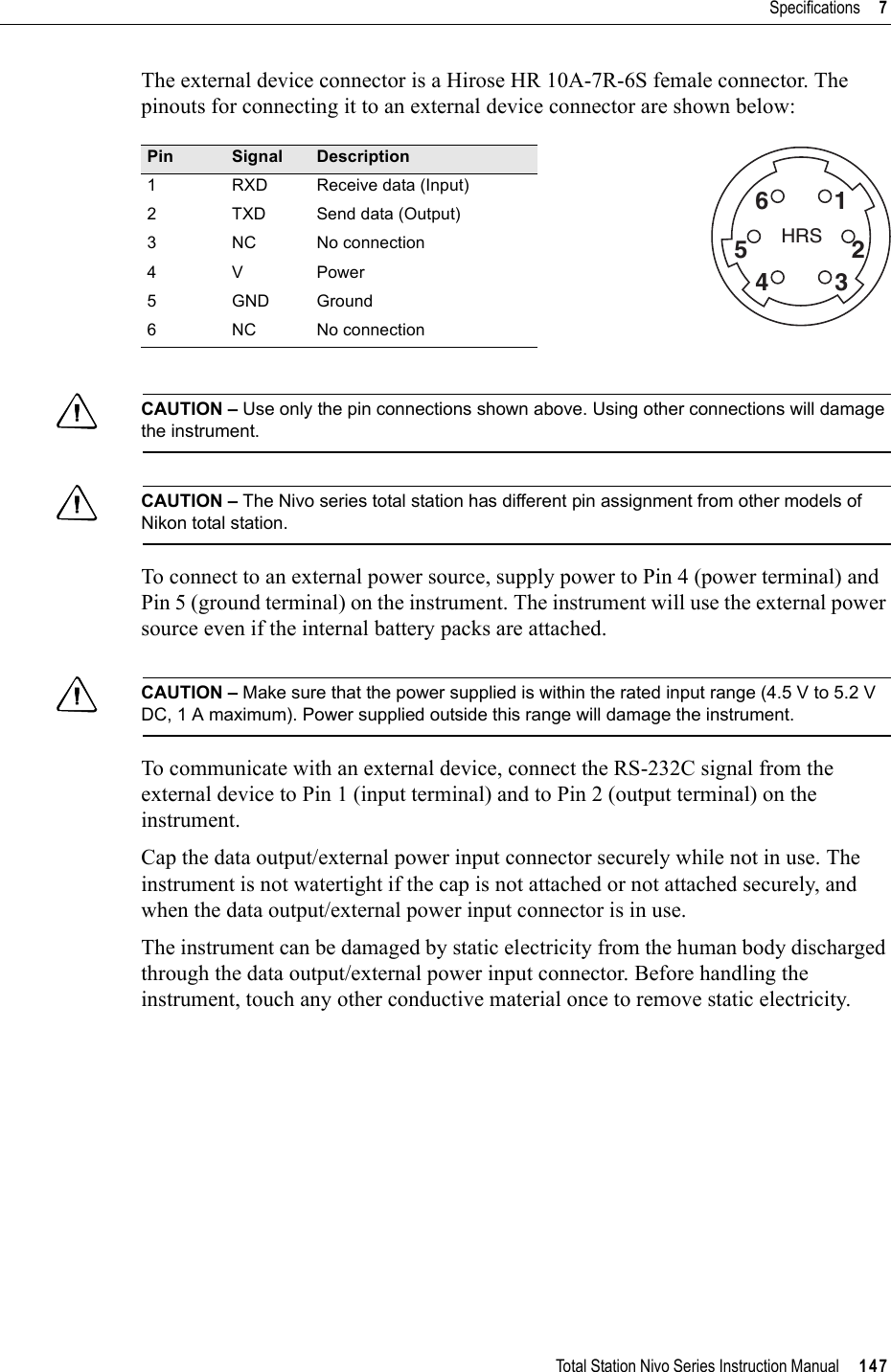
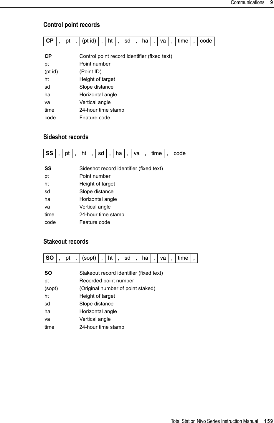
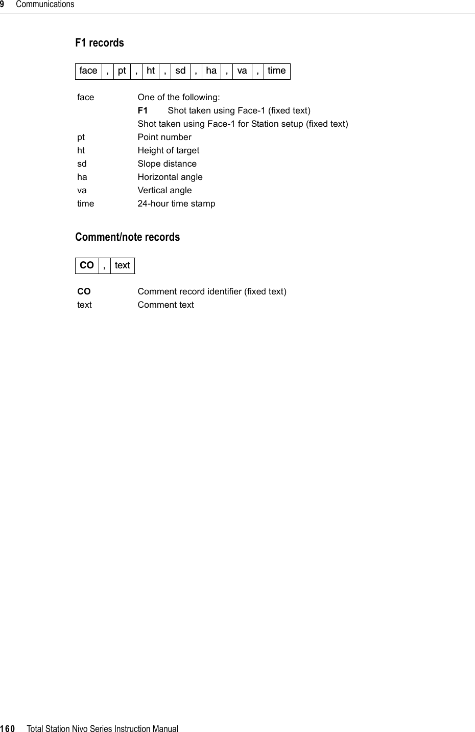
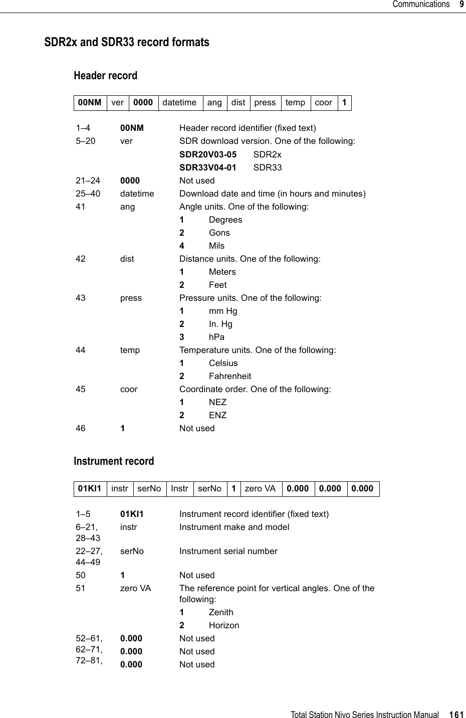
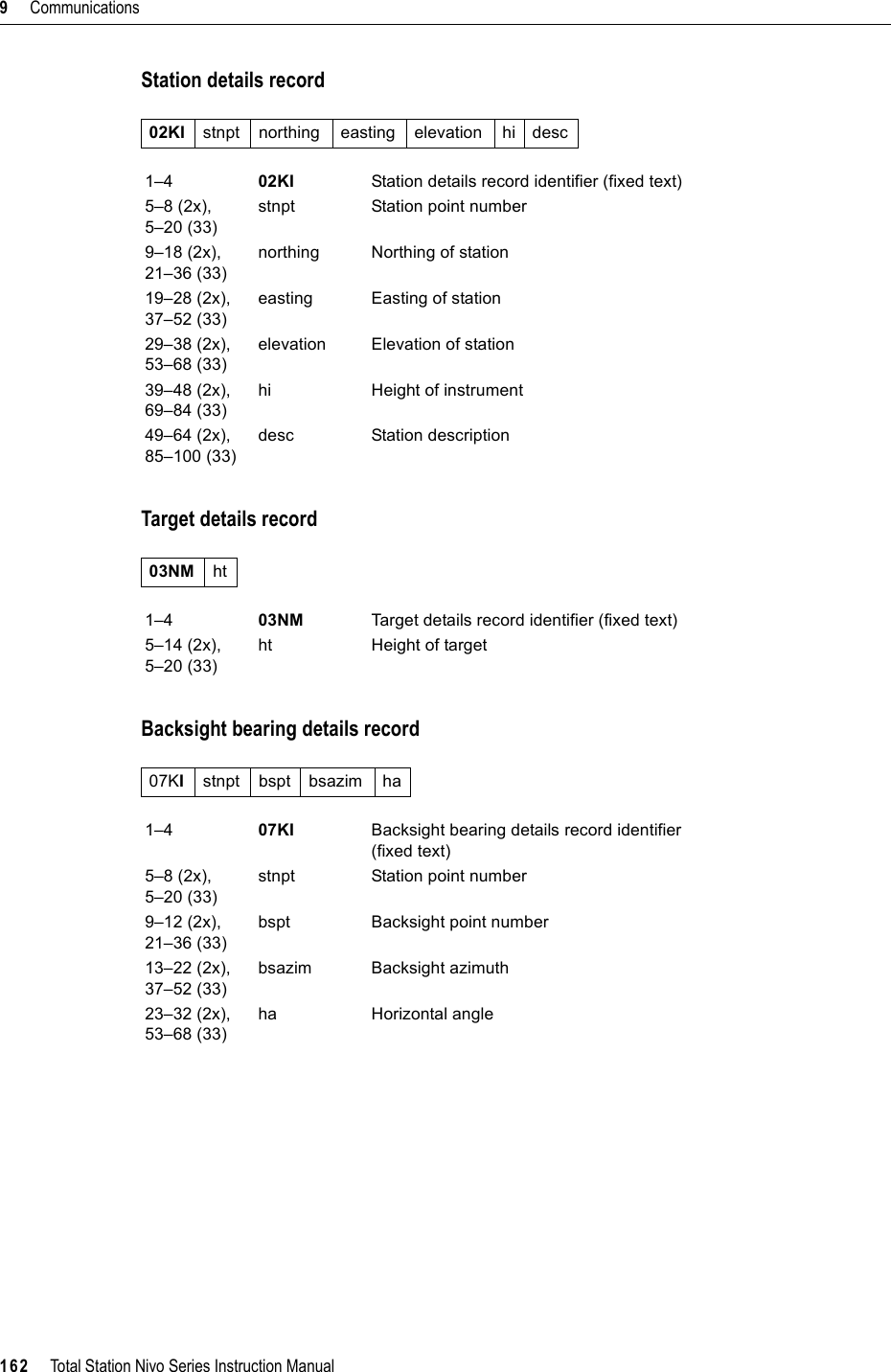
NIKON TRIMBLE NT0001 Bluetooth module User Manual Nivo manual 3
NIKON-TRIMBLE CO., LTD. Bluetooth module Nivo manual 3
UserManual.wiki
>
NIKON TRIMBLE
>
NT0001 User Manual
>
Host 2 user manual 3 of 3
Contents
1.
Host 1 user manual 1 of 4
2.
Host 1 user manual 2 of 4
3.
Host 1 user manual 3 of 4
4.
Host 1 user manual 4 of 4
5.
Host 2 user manual 1 of 3
6.
Host 2 user manual 2 of 3
7.
Host 2 user manual 3 of 3
8.
Host 3 user manual 1 of 2
9.
Host 3 user manual 2 of 2
Host 2 user manual 3 of 3
Navigation menu
Upload a User Manual
Namespaces
Wiki Guide
HTML
PDF
Info
Views
User Manual
Discussion / Help
Navigation
![5 Menu Key92 Total Station Nivo Series Instruction ManualIntroductionUse the MENU screen to access important functions and settings.To display the MENU screen, press the [MENU] key.Job ManagerUse the job manager to open, create, delete, and manage jobs. To open the Job Manager, press [1] or select Job on the MENU screen.If there are jobs stored on the instrument, the job list appears, showing all the stored jobs. The newest job appears at the top of the list.If there are no jobs stored, the Create Job screen appears. See Creating a new job, page 93.Opening an existing jobThe job list shows all the jobs stored on the instrument, in descending date order.The following symbols may be used to provide extra information about jobs:Press [^] or [v] to move up or down the job list. Press [ENT] to open the highlighted job.When you open a job, all job settings are automatically changed to match those used in the open job.Symbol Meaning* Current job.@ Control job.! Some of the job settings are different from the current job.? Job was created in an older DB. Older files cannot be opened in version 1.10 or later of the software.](https://usermanual.wiki/NIKON-TRIMBLE/NT0001.Host-2-user-manual-3-of-3/User-Guide-1089795-Page-2.png)
![Total Station Nivo Series Instruction Manual 93Menu Key 5Creating a new job1. Press the Creat softkey in the job list.2. Enter a job name of up to eight characters. Press [ENT].3. Do one of the following:–To check the job settings, press the Settsoftkey.–To create a new job using the current job settings, press [ENT] or the OK softkey.Job settingsThe following settings are set when a job is created, and cannot be changed. This ensures that the data in a job is correctly stored in the database, and that all necessary corrections are applied when you store each record.Scale Factor 0.999600 to 1.000400T-P correction ON/OFFSea Level ON/OFFC&R correction OFF/0.132/0.200Angle unit DEG/GON/MILDistance unit Metre/US-Ft/I-FtTemp unit °C/°FPress unit hPa/mmHg/inHgIf you select US-Ft or I-Ft, an additional settings screen appears. Use this screen to specify whether to display values in Decimal-Ft or Ft-Inch.VA zero Zenith/Horizon/CompassAZ zero North/SouthOrder NEZ/ENZHA Azimuth/0 to BS](https://usermanual.wiki/NIKON-TRIMBLE/NT0001.Host-2-user-manual-3-of-3/User-Guide-1089795-Page-3.png)
![5 Menu Key94 Total Station Nivo Series Instruction ManualTo move between fields, press [^] or [v]. Alternatively, to move to the next field, press [ENT].To change the setting in the selected field, press [<] or [>].To confirm the job settings and create the job, press [ENT] in the last field (HA).These settings are separate from other temporary settings.Deleting a jobBTip – There is no undelete function in the Job Manager. Before you press [ENT] or select DEL,make sure that the selected job is the one that you want to delete.1. In the job list, highlight the job that you want to delete.2. Press the DEL softkey. A confirmation screen appears.3. Do one of the following: –To delete the selected job, press [ENT] or the DEL softkey.–To cancel the deletion and return to the previous screen, press [ESC] or the Abrt softkey. After you delete a job, the display returns to the job list.Setting the control jobIf you search for a point when a control job is specified, and the system cannot find the point in the current job, the control job is also searched. If the point is found in the control job, it is copied to the current job as a UP record.A control job has the same format as a standard job. You can open and modify it like any other job, and you can use it to record any measured data.To set the control job:1. Highlight the job that you want to use.2. Press the Ctrl softkey.](https://usermanual.wiki/NIKON-TRIMBLE/NT0001.Host-2-user-manual-3-of-3/User-Guide-1089795-Page-4.png)
![Total Station Nivo Series Instruction Manual 95Menu Key 5A confirmation screen appears.3. Do one of the following:–To set the selected job as the control job, press [ENT] or the Yes softkey.–To cancel the process, press [ESC] or the Nosoftkey. Displaying job InformationTo display job information, highlight the job name and then press the Info softkey. The Information screen shows the number of records in the job, the free space, and the date when the job was created. Free space indicates how many points can be stored in the job.To return to the job list, press any key.If a control job is already assigned, the newly assigned control job replaces it as the control job.To clear the control job selected, highlight the current control job in the job list and press the Ctrl softkey. Then press [ENT] or the Yes softkey to confirm.](https://usermanual.wiki/NIKON-TRIMBLE/NT0001.Host-2-user-manual-3-of-3/User-Guide-1089795-Page-5.png)
![5 Menu Key96 Total Station Nivo Series Instruction ManualCogoUse the Cogo menu to perform coordinate geometry (COGO) calculations. You can access this menu at any time from any observation or PT input screen.To open the Cogo menu, press [2] or select Cogo on the MENU screen.Calculating angle and distance between two coordinatesTo open the Inverse menu, press [1] or select Inverse in the Cogo menu.PT-PT inversePT-PT calculates the distance and the angle between two input points. To calculate a PT-PT inverse:1. Press [1] or select PT-PT in the Inverse menu.2. Enter the first point number or name. Press [ENT].3. Type the second point number/name and press [ENT]. The MSR softkey allows you to shoot the point on the spot to use it in the calculation.The azimuth, horizontal distance, and vertical distance from the first point to the second point are displayed.If you press [ENT] without entering a point name, a coordinate input screen appears, and you can enter coordinates. These coordinates are not stored to the database. If you want to store the point, specify a new point name.](https://usermanual.wiki/NIKON-TRIMBLE/NT0001.Host-2-user-manual-3-of-3/User-Guide-1089795-Page-6.png)
![Total Station Nivo Series Instruction Manual 97Menu Key 54. Do one of the following:–To return to the PT input screen, press [ESC].–To return to the COGO menu, press [ENT].–To change the contents of the result screen, press [DSP].3Pt angleThe 3Pt Angle function calculates the angle between two lines defined by three points. To calculate a 3Pt angle:1. Press [2] or select 3Pt Angle in the Inverse menu. P1 is the base point. Two lines are to be defined by P2 and P3, both from P1.2. Enter the point name, or use the MSR softkey to take a measurement to the point.3. Enter the second point (P2) to define the baseline (P1-P2). The angle (dHA) is measured from the baseline.4. Enter the third point (P3) to define the second line (P1-P3).Gd Grade (HD/VD)V% 100/GdrSD Slope distance PT1 to PT2When you press the MSR softkey, a temporary measuring screen appears. Sight the target and press [MSR1] or[MSR2] to take a measurement.After the measurement, a recording point screen appears. To store the measured point, enter the PT, HT, and CD values and press [ENT]. To use the point without recording it, press [ESC].](https://usermanual.wiki/NIKON-TRIMBLE/NT0001.Host-2-user-manual-3-of-3/User-Guide-1089795-Page-7.png)
![5 Menu Key98 Total Station Nivo Series Instruction ManualWhen you have entered three points, the instrument calculates the angle and distances.5. Do one of the following:–To return to the Inverse menu, press [ENT].–To return to the Input BasePt screen, press [ESC].Calculating and manually inputting coordinatesTo enter the Input menu, press [2] or select Input in the Cogo menu. There are three functions in this menu for recording new coordinate points.Azimuth+HD inputTo calculate a coordinate by an angle and distance input from the base point (P1), press [1] or select AZ+HD in the Input menu.Enter the base point (P1). Type the point name and press [ENT].Enter the azimuth, horizontal distance, and vertical distance. Then press [ENT].To enter 123°45'45", type 123.4545 and press [ENT].If you do not enter a value in the dVD field, the value 0.000 is used.A recording point screen with the calculated coordinates appears. PT defaults to the last recorded PT + 1.Press [ENT] to store the point.](https://usermanual.wiki/NIKON-TRIMBLE/NT0001.Host-2-user-manual-3-of-3/User-Guide-1089795-Page-8.png)
![Total Station Nivo Series Instruction Manual 99Menu Key 5TraverseTo open the Traverse (2Pt Angle) function, press [2] or select Traverse in the Input menu.Traverse function calculates a new point based on the two defined points and angle, horizontal and vertical distances from the line defined by those two points.To enter P1 and P2, enter point names or take measurements to targets.Enter the plus-minus angle, horizontal distance, and vertical distance from the baseline defined by P1-P2.If you do not enter a value in the dVD field, the value 0.000 is used.When you press [ENT] in the dVD field, a new point is calculated. The PT name defaults to the last recorded PT + 1. To record the new point and return to the point input screen, press [ENT].P1 (base PT) defaults to the previously recorded PT. P2 defaults to the previous P1.Entering coordinatesTo manually enter the XYZ coordinates, press [3] or select Input XYZ in the Input menu.The PT name defaults to the last recorded PT + 1.Enter the coordinates using the numeric keys. To move to the next field, press [ENT] or [v] in a field To continuously calculate a new point, enter +Ang, HD, and dVD from the previous bearing line. This is a convenient way to enter Traverse points.](https://usermanual.wiki/NIKON-TRIMBLE/NT0001.Host-2-user-manual-3-of-3/User-Guide-1089795-Page-9.png)
![5 Menu Key100 Total Station Nivo Series Instruction ManualTo store the point as an MP record and return to the point input screen, press [ENT] in the Z field. The default PT is incremented to the next value.Calculating area and perimeterTo calculate an area or perimeter, press [3] or select Area & Perim in the Cogo menu. To take a measurement, enter the first point and press [ENT], or press the MSR softkey. In the upper right corner of the screen, a counter indicates how many points you have entered.To input point numbers consecutively, use the Fr/Tosoftkey. For more information, see Advanced feature: Entering a range of points, page 101.If you enter a new point name, you can enter new coordinates and record the point. If you do not want to record the point, press [ENT] without entering a value in the PT field. An XY coordinate input screen appears.Continue to enter points until you have defined all the points in the lot. Then, press [v] to calculate the area and perimeter.Press [ENT] to store the calculated values as a a comment record, or press [ESC] to return to the Cogo menu.You can record NE, NEZ, or Z-only data to the database.The first and last points that you enter are joined to close the area.You must enter the points in the order in which they define the lot.You can enter up to 99 points.](https://usermanual.wiki/NIKON-TRIMBLE/NT0001.Host-2-user-manual-3-of-3/User-Guide-1089795-Page-10.png)
![Total Station Nivo Series Instruction Manual 101Menu Key 5If you chose to store the area, enter a name to identify the area and then press [ENT].Advanced feature: Entering a range of pointsTo quickly enter a sequential range of points, use the range input function. To access this function, press the Fr/To softkey in the No. 01 or No. 02 input screens.Enter the start point name in the Fr field and the end point name in the To field. You can include letters and hyphens in the point names, but the last character must be numeric.Press [ENT] in To field to start searching for matching points. The counter shows the number of matching points found.When the search is complete, you are returned to the Input PT screen.Press the Calc softkey to calculate the area and perimeter, or enter point names in the PT field.Press [ESC] to return to the Input PT screen with the preceding point name.When you download data in Nikon RAW format, area (AR) records are output as comment (CO) records.](https://usermanual.wiki/NIKON-TRIMBLE/NT0001.Host-2-user-manual-3-of-3/User-Guide-1089795-Page-11.png)
![5 Menu Key102 Total Station Nivo Series Instruction ManualCalculating coordinates from line and offsetTo enter the Line & offset function, press [4] or select Line & O/S in the Cogo menu. Enter the base point (P1). Specify the azimuth bearing. To do this, enter a value in the AZ or P2 field. P2 is a second point on the line. Enter the horizontal distance along the baseline (Sta), the horizontal distance perpendicular to the line (O/S), and the vertical distance (dVD).To calculate the coordinates of the point (PM), press [ENT] in the dVD field. You can change the Z coordinate here.To record the point, press [ENT] in the CD field. A negative value in the Sta field means the opposite direction along the defined bearing line.A negative value in the O/S field is for the left-hand side of the bearing line.](https://usermanual.wiki/NIKON-TRIMBLE/NT0001.Host-2-user-manual-3-of-3/User-Guide-1089795-Page-12.png)
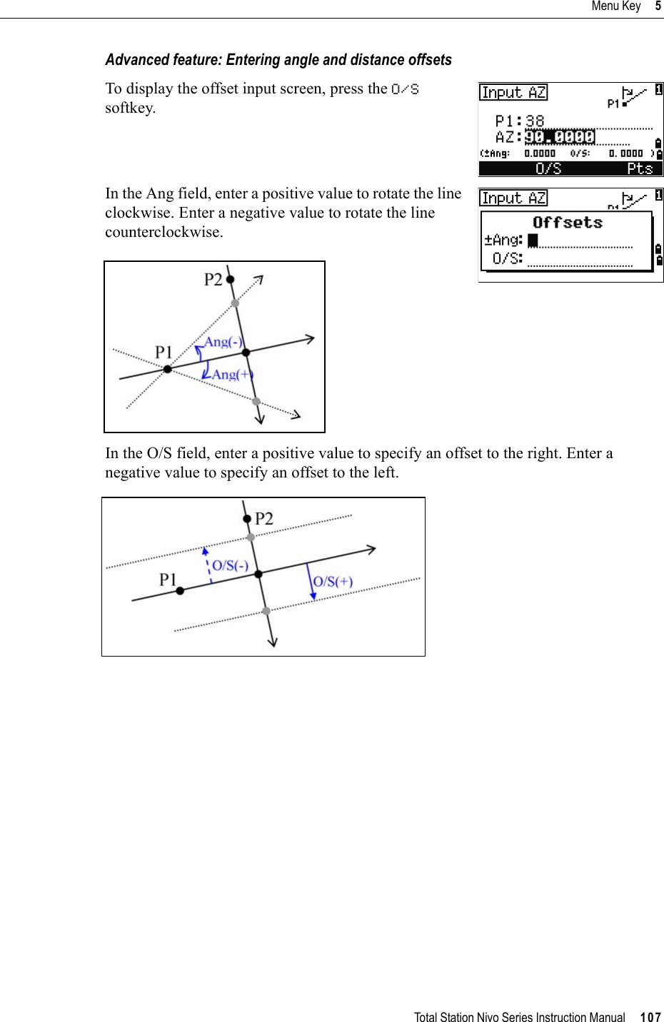
![Total Station Nivo Series Instruction Manual 103Menu Key 5The coordinates are stored as a CC record. Line definition information and Sta, O/S, and dVD values are stored in comment (CO) records.Calculating coordinates using intersection functionsTo enter the Intersection menu, press [3] or select Intersection in the Cogo menu. There are four functions in this menu for calculating coordinates.Calculating a bearing-bearing intersectionA bearing-bearing intersection is the intersection point of two lines.1. To calculate a bearing-bearing intersection, press [1] or select Brng-Brng in the Intersection menu. 2. Enter the first point name and press [ENT].Alternatively, to measure directly to the point, press the MSR softkey. 3. Define the first line by azimuth.4. To define the line by two points, press the Ptssoftkey. The Fr field defaults to the P1 point, but you can change the selected point. In the To field, enter or measure to the second point.For more information about the O/S softkey, see Advanced feature: Entering angle and distance offsets, page 107.5. Do one of the following:–To return to the previous screen, press [ESC].The calculated value appears in the AZ field. –To go to the next screen, press [ENT].](https://usermanual.wiki/NIKON-TRIMBLE/NT0001.Host-2-user-manual-3-of-3/User-Guide-1089795-Page-13.png)
![5 Menu Key104 Total Station Nivo Series Instruction Manual6. Define the second line by two points or by P2 and AZ.7. To calculate the coordinates of the intersection point, press [ENT] in the AZ field. The calculated coordinates are displayed. You can input a Z coordinate if necessary.8. Enter a value in the PT field and in the CD field. 9. To record the point, press [ENT].Sample recordsCO,Int BB P1:P10 AZ:330.54175-90.00000CO, P2:408 AZ:100.0000+0.0000CC,A123,,4567.3080,200.1467,-1.2056,POTCalculating a bearing-distance intersection1. Press [2] or select Brng-Dist in the Intersection menu.Brng-Dist calculates the intersection point formed by one line and one distance (radius).2. Enter a point on the line.The line can be defined by two points or by a point and an azimuth.3. Enter the second point (P2) as the center of the circle.](https://usermanual.wiki/NIKON-TRIMBLE/NT0001.Host-2-user-manual-3-of-3/User-Guide-1089795-Page-14.png)
![Total Station Nivo Series Instruction Manual 105Menu Key 54. Enter the distance from P2.–To define the distance (HD) by two points, press the Pts softkey.–To calculate the coordinates of the intersection point, press [ENT] in the HD field. 5. If there are two results, the first solution appears graphically relative to the P1-P2 line. To display the second solution, press [<] or [>].6. To record the point, press [ENT] when the required solution appears.7. Enter a Z coordinate if necessary. 8. To move to the PT and CD fields, press [ENT].Sample recordsCO,Int BD P1:4672 AZ:330.54175+0.00000CO, P2:71 HD:100.0000CC,504,,-839.3065,347.6682,,SIGNCalculating a distance-distance intersection1. Press [3] or select Dist-Dist in the Intersection menu.2. Enter the first point name and press [ENT], or press the MSR softkey to measure directly to the point.3. Enter the distance from P1 and press [ENT].4. To define the distance (HD) by two points, press the Pts softkey.5. Enter P2 and the distance from P2 (HD).6. To calculate the coordinates of the intersection point, press [ENT] in the HD field.](https://usermanual.wiki/NIKON-TRIMBLE/NT0001.Host-2-user-manual-3-of-3/User-Guide-1089795-Page-15.png)
![5 Menu Key106 Total Station Nivo Series Instruction Manual7. Press [<] or [>] to display the second solution.8. To record the point, press [ENT] when the required solution appears.9. Enter a Z coordinate if necessary. Press [ENT] to move to the PT and CD fields.Sample recordsCO,Int DD P1:486 HD:330.6020CO, P2:7 HD:100.0000CC,505,,236.5817,50.0461,0.0000,Calculating a point-line intersection1. Press [4] or select Pt-Line in the Intersection menu.2. Enter the first point name and press [ENT], or press the MSR softkey to measure directly to the point.3. Enter the azimuth, or press the Pts softkey to enter another point name on the line.4. Enter the perpendicular point to the line, or press the MSR softkey to take a measurement to the point.5. To calculate the coordinates of the intersection point, press [ENT].If P1 and P2 are 3D points, the Z coordinate of the perpendicular point is calculated relative to the P1-P2 slope.6. Enter PT and CD then press [ENT] to record the point.Sample recordsCO,Int PtLine P1:38 AZ:90.00000+0.00000CO, P2:506CC,A-123,,4567.3080,200.1467,-1.2056,POT](https://usermanual.wiki/NIKON-TRIMBLE/NT0001.Host-2-user-manual-3-of-3/User-Guide-1089795-Page-16.png)
![5 Menu Key108 Total Station Nivo Series Instruction ManualSettingsTo display the Settings menu, press [2] or select Settings on the MENU screen.Use this menu to configure the initial job settings.AngleTo open the Angle menu, press [1] or select Angle in the Settings menu.Some job settings, specified in the following sections, cannot be changed once a job is created. If any of these settings are changed while a job is open, a confirmation screen appears, asking you to create a new job with the new settings, or to work with those settings without recording any data. For more information, see Settings, page 174.VA zero Zenith/Horizon/CompassThe VA zero job setting cannot be changed once a job is created.Resolution 1"/5"/10" or 0.2 mgon/1 mgon/2 mgonHA 0 to BS/AzimuthThe HA job setting cannot be changed once a job is created.When this field is set to Azimuth, the horizontal angle (HA) that appears and recorded is in Azimuth value. When this field is set to 0 to BS, HA is in HA zero to BS value.](https://usermanual.wiki/NIKON-TRIMBLE/NT0001.Host-2-user-manual-3-of-3/User-Guide-1089795-Page-18.png)
![Total Station Nivo Series Instruction Manual 109Menu Key 5DistanceTo open the Distance menu, press [2] or select Distance in the Settings menuTemperature and Pressure correctionsSea Level correction Curvature and Refraction correctionBecause the surface of the earth is curved, the vertical difference (VD and Z) at the measurement point, as referenced to the horizontal plane, inevitably includes some error. This error is called curvature error. Also, because the density of the air Scale Numeric value between 0.999600 and 1.000400T-P corr. ON/OFFSea Level ON/OFFC&R corr. OFF/0.132/0.200The Scale, T-P corr., Sea Level, and C&R corr. job settings cannot be changed once a job is created.SD Slope dist. (before adj.) SD' Slope dist. (after adj.)K Compensation coefficientP Pressure (hPa)T Temperature (°C)HD Horizontal dist. (before adj.)HD' Horizontal dist. (after adj.)ZSTN Instrument-ZRe6370 kmK275106 P 10000.013.5951 980.665×---------------------------------------------©¹§·××273 T+---------------------------------------------------------------------------–=SD' 1 K1000000---------------------+©¹§·SD×=HD' HD Re×ReZSTN+------------------------=](https://usermanual.wiki/NIKON-TRIMBLE/NT0001.Host-2-user-manual-3-of-3/User-Guide-1089795-Page-19.png)
![5 Menu Key110 Total Station Nivo Series Instruction Manualsurrounding the earth decreases with altitude, light is refracted at different rates at different altitudes. The error caused by this change in refraction is called refraction error.CoordinateTo open the Coordinate menu, press [3] or select Coord. in the Settings menu. Power savingTo open the Power Save menu, press [4] or select PwrSave in the Settings menu. HD Horizontal dist. (before adj.)HD’ Horizontal dist. (after adj.)VD Vertical dist. (before adj.)VD' Vertical dist. (after adj.)SD Slope distanceVA Vertical angleRe 6370 kmk C&R constant (0.132 or 0.200)Order NEZ/ENZLabel XYZ/YXZ/NEZ(ENZ)AZ North/SouthThe Order and AZ job settings cannot be changed once a job is created.Main Unit OFF/5min/10min/30minEDM Unit OFF/At once/0.1min/0.5min/3min/10minSleep OFF/1min/3min/5minCurvature error (A A') Refraction error (A A1')PA'HorizontaldirectionAOPA1'A1A'HD' HD SD22VA()sin2Re----------------------------------- 1 k2---–©¹§·–=VD' VD HD22Re-----------1 k–()+=](https://usermanual.wiki/NIKON-TRIMBLE/NT0001.Host-2-user-manual-3-of-3/User-Guide-1089795-Page-20.png)
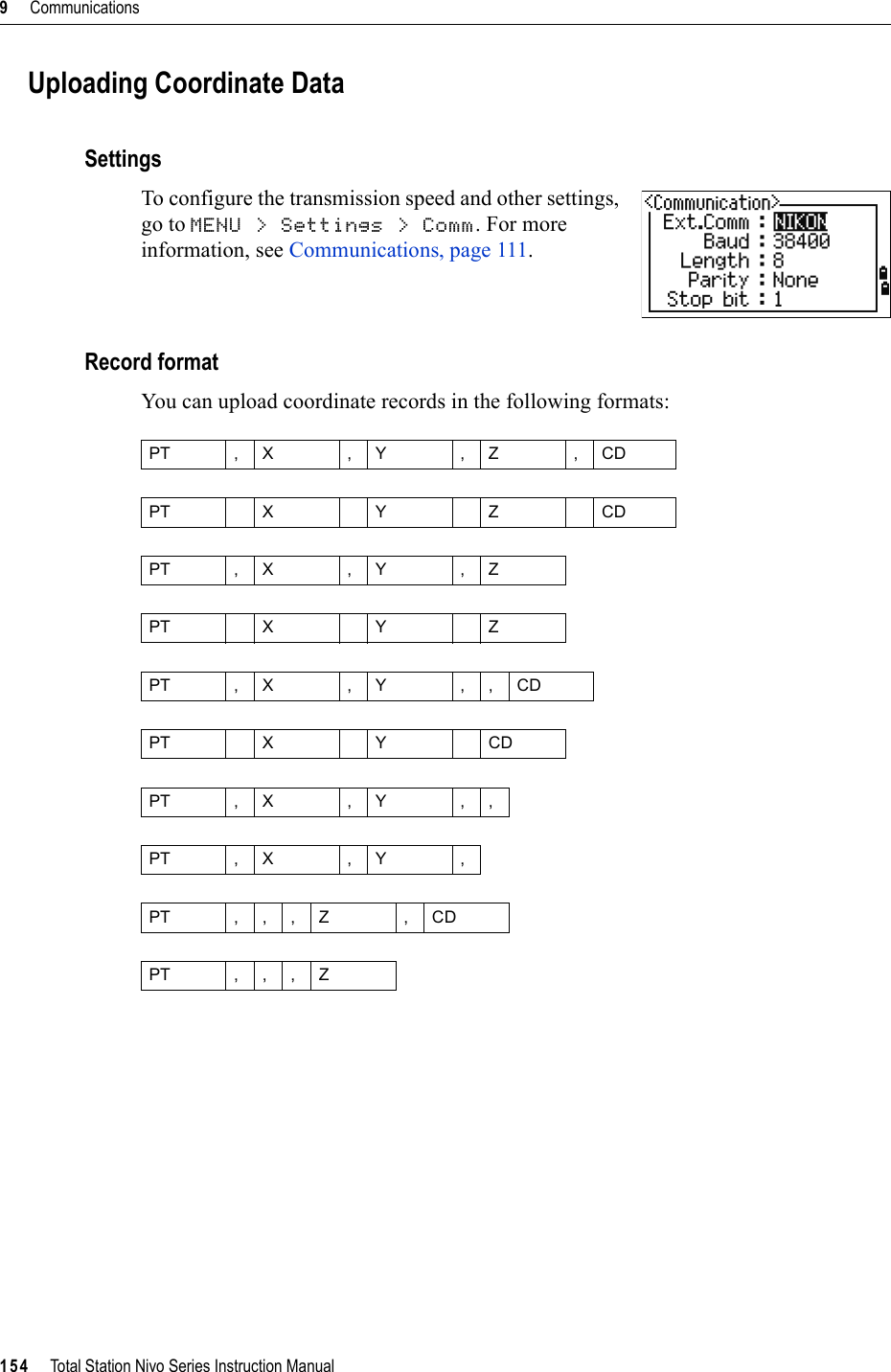
![Total Station Nivo Series Instruction Manual 111Menu Key 5CommunicationsTo open the Communication menu, press [5] or select Comm. in the Settings menu. StakeoutPress [6] or select Stakeout in the Settings menu to open the Stakeout menu..UnitTo open the Unit menu, press [7] or select Unit in the Settings menu. Ext.Comm NIKON/SETPort Serial/Bluetooth (*)Baud 1200/2400/4800/9600/19200/38400 bpsLength 7/8Parity EVEN/ODD/NONEStop bit 1/2(*) Port selection field appears only when the optional Bluetooth is on-board.Add PT Integer between 1 and 999,999This field sets the default point number to record observed data in stakeout.Angle DEG (Degree)GON (GON)MIL (Mil6400)Distance Meter/US-Ft/I-FIf you select US-Ft or I-Ft, an additional settings screen appears. Use this screen to specify whether to display values in Decimal-Ft or Ft-Inch.Temp °C (Celsius)°F (Fahrenheit)Press hPa/mmHg/inHgThe Angle, Distance, Temp, and Press job settings cannot be changed once a job is created.](https://usermanual.wiki/NIKON-TRIMBLE/NT0001.Host-2-user-manual-3-of-3/User-Guide-1089795-Page-21.png)
![5 Menu Key112 Total Station Nivo Series Instruction ManualRecordingTo open the Rec menu, press [8] or select Angle in the Settings menu.Others settingsTo open the Others menu, press [9] or select Others in the Settings menu. Store DB RAW/XYZ/RAW+XYZThis setting determines whether raw and/or coordinate data is stored when you record SS, CP, or SO records in the Basic Measurement Screen (BMS) or Stakeout screen.Data Rec Internal/COMSet this field to COM to output data on the COM port when you press [ENT] in the BMS or a Stakeout screen. The data is not stored to the job file. For more information, see Outputting data to the COM port, page 82XYZ disp Fast/Norm/Slow/+ENTDefines speed to move to the next screen after showing XYZ of the input PT2nd Unit None/Meter/US-Ft/I-FtWhen the Secondary unit is set to a unit, an extra display screen is available in the BMS, stakeout observation screens, and 2-pt reference line screens. The extra screen shows the HD, VD, and SD in the secondary unit.If you select US-Ft or I-Ft, an additional settings screen appears. Use this screen to specify whether to display values in Decimal-Ft or Ft-Inch.Split ST No/YesSelect Yes to separate the point numbers of station points from other record type point numbersIf you set the Split ST field to Yes, an additional setting screen appears. Use this screen to specify the starting ST number.](https://usermanual.wiki/NIKON-TRIMBLE/NT0001.Host-2-user-manual-3-of-3/User-Guide-1089795-Page-22.png)
![Total Station Nivo Series Instruction Manual 113Menu Key 5BTip – To provide easier configuration for common regional settings, you can quickly configure the Nikon total station to a pre-set combination of default regional settings. For more information, see Changing Regional Configuration Pre-sets, page 25.BTip – The Nikon total station supports up to 3 languages on the instrument. For more information on changing the language settings, see page 113.CD Input ABC/123Sets the default input mode when a CD field appears.Language Select a language from the list.Press [<] /[>] to open the select language screen.Press [^] /[v] to move the cursor to the desired language, and press [ENT] to select it.Reboot confirmation screen appears.Press [ENT] and re-start the instrument, and the selected language will be available.Owner’s Detail Up to 20 characters.Enter your name or the name of your company. If you enter a value in this field, it appears at start-up.](https://usermanual.wiki/NIKON-TRIMBLE/NT0001.Host-2-user-manual-3-of-3/User-Guide-1089795-Page-23.png)
![5 Menu Key114 Total Station Nivo Series Instruction ManualDataUse the Data menu to view or edit records. To display the Data menu, press [4] on the MENU screen.Viewing recordsViewing raw dataTo show the raw data records in a list, press [1] on the Data menu screen.When you first view the raw data, the last four raw records in the current job are displayed. Use [^] or [v] to scroll through the records.To see detailed information for the selected records, press [ENT].To return to the record list, press [ESC].SS, CP, F1 recordsRaw SS, CP and F1 records contain PT, HT, CD, HA, VA, and SD fields.SS records are sideshots (topo shots). All shots from the Basic Measurement Screen (BMS) are stored as SS records.CP records are shots taken in the Angle or Repeat menus, or in the BMS. For more information, see Recording a foresight point after repeat angle measurement, page 52,and Recording data from any observation screen, page 81.When the Store DB setting is set to RAW+XYZ, press [DSP] to switch between the first screen (showing HA, VA, SD, PT, and HT) and the second screen (showing X, Y, Z, PT, and CD).Coordinates are not available in F1 records.When you take more than one measurement to the same point and choose to overwrite the XYZ data, the old raw record becomes raw data only. As a result, only one SS(RAW) record keeps its corresponding SS(XYZ) record. Other SS(RAW) records to the same point no longer have coordinates available.You can view data at any time, even in an observation screen or while entering points.](https://usermanual.wiki/NIKON-TRIMBLE/NT0001.Host-2-user-manual-3-of-3/User-Guide-1089795-Page-24.png)
![Total Station Nivo Series Instruction Manual 115Menu Key 5ST recordsST (station) records contain ST, HI, BS, and AZ fields. Press [DSP] to switch between the first screen (showing ST, HI, BS, and AZ) and the second screen (showing X, Y, Z, PT, and CD).When you assign a new ST point name in MENU > Stn Setup > Quick, the coordinates of the station is recorded as (0, 0, 0).SO recordsSO records are stakeout shots. These are shots recorded in stakeout functions.When the Store DB setting is set to RAW+XYZ, press [DSP] to switch between the first screen (showing HA, VA, SD, PT, and HT), the second screen (showing X, Y, Z, PT, and CD), and the third screen (showing dX, dY, dZ, PT, and CD).The dX, dY, and dZ fields store the difference between the stakeout shot’s actual position and its planned position. These fields are downloaded as comment records in Nikon RAW format.CO recordsA CO record is a comment added to the job from the system.For example, when you change the Stn-Z using the Remote Benchmark function, or you reset the horizontal angle using the BSCheck function, the system writes a comment record.When you input a Stn-XYZ by Base-XYZ function, the recorded station appears as a comment record.SY recordsWhen you complete a station setup, a SY record is stored. This record contains the Temperature, Pressure, and Prism Constant values.](https://usermanual.wiki/NIKON-TRIMBLE/NT0001.Host-2-user-manual-3-of-3/User-Guide-1089795-Page-25.png)
![5 Menu Key116 Total Station Nivo Series Instruction ManualRM recordsWhen you record measurements in RDM (Cont) or RDM (Rad), they are labeled as RM records.Each RM record consists of two screens.Press [DSP] to switch between the first screen (showing From, To, rHD, and rVD) and the second screen (showing rAZ, rSD, rV%, and rGD).When you download data in Nikon RAW format, RM records are output as comment (CO) records.AR recordsAn AR record stores an area and perimeter calculation.When you download data in Nikon RAW format, AR records are output as comment (CO) records.View coordinate dataWhen you press [2] or select XYZ data in the Data menu, coordinate data appears in a list, with the newest record at the bottom of the screen. Use [^] or [v] to scroll through the records. Use [<] or [>] to move up or down one page.Press [ENT] to see more detailed information about the selected record.UP, MP, CC, and RE recordsAll coordinate records contain PT, CD, X, Y, and Z fields.UP records are uploaded point coordinates. MP records are manually input point coordinates. CC records are points calculated in Cogo, and RE records are points calculated in Resection.The header (XYZ,YXZ,NEZ, or ENZ) depends on the Coord. Label setting in MENU > Settings > Coord. For more information, see Coordinate, page 110.](https://usermanual.wiki/NIKON-TRIMBLE/NT0001.Host-2-user-manual-3-of-3/User-Guide-1089795-Page-26.png)
![Total Station Nivo Series Instruction Manual 117Menu Key 5When the Store data setting is set to RAW+XYZ or to XYZ, shots in the BMS (SS records), in various O/S functions (SS records), in 2Pt-RefLine and Arc-RefLine in PRG (SS records) and in some Stakeout functions (SO records) store coordinate records as well. The format of the data is the same as other coordinate records.View records by stationTo view records by station, press [3] or selectST->SS/SO/CP in the Data menu.A list of all stations appears.Use [^] or [v] to highlight the station name that you want to view. Use [<] or [>] to move up or down one page.To view detailed information about the selected station, press [ENT].To display all the observation data from the selected station in chronological order, press [ENT] again.Deleting recordsDeleting raw recordsIn the RAW screen, use [^] or [v] to highlight the record that you want to delete. Then press the DEL softkey.A confirmation screen appears. To delete the selected record, press [ENT] or the Yes softkey.Detailed data is as for raw data. For detailed information about each point type and format, see Viewing raw data, page 114.](https://usermanual.wiki/NIKON-TRIMBLE/NT0001.Host-2-user-manual-3-of-3/User-Guide-1089795-Page-27.png)
![5 Menu Key118 Total Station Nivo Series Instruction ManualDeleting coordinate recordsIn the XYZ screen, use [^] or [v] to highlight the record that you want to delete. Then press the DEL softkey.A confirmation screen appears.To delete the selected record, press [ENT] or the Yessoftkey. To cancel the deletion of data, press [ESC] or the Nosoftkey.Deleting station recordsIn the Station screen, use [^] or [v] to highlight the record that you want to delete. Then press the DEL softkey.If the Store DB setting is set to Both, the system also deletes the corresponding coordinate data when you delete an SS, SO, or CP record.You can also delete raw data by pressing the DEL softkey in the detailed display screen for the record.You can also delete coordinate data by pressing the DEL softkey in the detailed display screen for the record.If the record that you want to delete is referred by an ST record, a confirmation message appears.](https://usermanual.wiki/NIKON-TRIMBLE/NT0001.Host-2-user-manual-3-of-3/User-Guide-1089795-Page-28.png)
![Total Station Nivo Series Instruction Manual 119Menu Key 5A confirmation screen appears.Press [ENT] or the Yes softkey to delete the selected record.A reconfirmation screen appears. Press the DELsoftkey to confirm deletion.There is no undelete function on the instrument. Before you press the DEL softkey, make sure that you have selected the correct station record. You cannot press [ENT] in this screen.All observations from the station that you selected are deleted.Editing recordsFor any point record, you can edit the point name (PT), feature code (CD), height of target (HT), height of instrument (HI), backsight point (BS), and backsight azimuth (AZ).Editing raw records1. Do one of the following:–In the RAW screen, highlight the record that you want to edit. Then press the Editsoftkey.–In the detailed data screen, press the Editsoftkey.When you delete a ST record in the raw data view or the station data view, all the observation data from the station is also deleted.You cannot edit the CD field for SO or F1 records.You cannot edit the HA, VA, or SD values.](https://usermanual.wiki/NIKON-TRIMBLE/NT0001.Host-2-user-manual-3-of-3/User-Guide-1089795-Page-29.png)
![5 Menu Key120 Total Station Nivo Series Instruction Manual2. Use [^] or [v] to highlight a field. Then modify the value in the selected field.3. When you press [ENT] on the last line of the edit screen, a confirmation screen appears.4. Do one of the following:–To accept the changes and return to the data view screen, press [ENT] or the Yes softkey. –To return to the edit screen, press [ESC] or the No softkey. Editing coordinate recordsYou can edit PT, CD, and coordinate values in coordinate records.1. Do one of the following:–In the XYZ screen, use [^] or [v] to highlight the record that you want to edit. Then press the Edit softkey.–In the detailed data screen, press the Editsoftkey.2. Use [^] or [v] to highlight a field. Then modify the value in the selected field.3. To finish editing, press [ENT] in the CD field.When you change the HT of an SS, SO, or CP measurement record, its Z coordinate is recalculated.You cannot edit the coordinate record for the current station.](https://usermanual.wiki/NIKON-TRIMBLE/NT0001.Host-2-user-manual-3-of-3/User-Guide-1089795-Page-30.png)
![Total Station Nivo Series Instruction Manual 121Menu Key 5A confirmation screen appears.4. Do one of the following:–To accept the changes and return to the data view screen, press [ENT] or the Yes softkey. –To go back to the edit screen, press [ESC] or the No softkey. Editing station recordsNote – The system will not recalculate measurements if you change the station record. All coordinate and raw data observed from an edited station record must be recalculated in your postprocessing software.In the RAW screen, use [^] or [v] to highlight the station record that you want to edit. Then press the Editsoftkey.You can edit any field in the ST record, but the instrument does not recalculate any measurements from this station.Press [ENT] in the AZ field to confirm the change.If you change the ST or HI values, the coordinates of observation points are not recalculated. A comment record is stored to record the change. The following example shows a comment record for a changed HI value:CO,HI changed at ST:9012 Old HI= 1.345mIf you change the BS or AZ values, raw records are not recalculated. A comment record is stored to record the change.](https://usermanual.wiki/NIKON-TRIMBLE/NT0001.Host-2-user-manual-3-of-3/User-Guide-1089795-Page-31.png)
![5 Menu Key122 Total Station Nivo Series Instruction ManualSearching recordsYou can search for records by their type, point name, code, or by any combination of these values.Searching raw recordsIn the RAW screen, press the Srch softkey to access the raw data search function.To find a point by name, enter the name in the PT field and press [ENT] twice.You can use the asterisk (*) as a wildcard. For example, when you enter 30* in the PT field, the search matches the points named 300, 301, 302, 3000A2, and 3010.If more than one point matches the search criteria, the matching points are displayed in a list.Use [^] or [v] to highlight the point you want to use. Then press [ENT] to select it.Detailed data for the selected record appears. Press the DSP softkey to change the fields shown.Press [ESC] to return to the list.To search by point type, move to the Type field and use [<] or [>] to change the selected point type. The options are ALL, ST, SS, SO, CP, CO, CO(SY), and CO(RDM).If you selected ST, SO or F1 in the Type field, you do not have to enter a value in the CD field. Press [ENT] in the PT field to start the search.If you selected CO, CO(SY), or CO(RDM) in the Type field, you cannot enter a value in the PT or CD fields. Press [ENT] in the Type field to start the search.](https://usermanual.wiki/NIKON-TRIMBLE/NT0001.Host-2-user-manual-3-of-3/User-Guide-1089795-Page-32.png)
![Total Station Nivo Series Instruction Manual 123Menu Key 5Searching coordinate recordsIn the XYZ screen, press the Srch softkey to access the XYZ data search function.To find a coordinate by name, enter the name in the PT field and press [ENT] twice.You can use the asterisk (*) as a wildcard. For example, when you enter 500* in the PT field, the search matches the points named 500, 500-1, 500-A, and 5000.If more than one point matches the search criteria, the matching points are displayed in a list.Use [^] or [v] to highlight the point you want to use. Press [ENT] to select it.Detailed data for the selected record appears. Press the DSP softkey to change the fields shown.Press [ESC] to return to the list.If no point matches the specified criteria, an error screen appears. Press any key to return to the data screen.To search by point type, move to the Type field and use [<] or [>] to change the selected point type. The options are ALL, MP, UP, CC, and RE.](https://usermanual.wiki/NIKON-TRIMBLE/NT0001.Host-2-user-manual-3-of-3/User-Guide-1089795-Page-33.png)
![5 Menu Key124 Total Station Nivo Series Instruction ManualEntering coordinatesIn the XYZ screen, press the Input softkey to display a new input point screen.The PT field defaults to the last recorded PT + 1, but you can change the value shown.Enter the PT and CD and then press [ENT] to enter coordinates.Use the numeric keys to enter the coordinates. Press [ENT] or [v] in each field to move to the next field.When you press [ENT] in the CD field, the point is stored as an MP record.After you have recording a point, the next point input screen is shown with the updated default PT.Point name list and code listThe instrument stores two list files: a list of PT names and a list of CD names. The structure and functionality of these files is the same.•The PT name list is useful if you have to handle more than one patterns of point names in the field. For example, you may need to use points named 1, 2, 3 …, as well as points named A1, A2, A3 ….•The code list is a prepared list of feature codes. You can use it to store your own codes.If no point matches the specified criteria, an error screen appears. Press any key to return to the data screen.You can record NE, NEZ, or Z-only data to the database.](https://usermanual.wiki/NIKON-TRIMBLE/NT0001.Host-2-user-manual-3-of-3/User-Guide-1089795-Page-34.png)
![Total Station Nivo Series Instruction Manual 125Menu Key 5Press [4] or select PT name List in the Data menu to open the point name list.Press [5] or select Code list to open the code list.The point or code names and layers are shown in alphabetic order. Use the four softkeys to customize the list.Deleting points, codes, or layersIn the point or code list, use [^] or [v] to highlight the item you want to delete. Then press the DEL softkey.A confirmation screen appears. Press [ENT] or the Yessoftkey to delete the item.Press [ESC] or the No softkey to cancel the deletion.You can store up to 254 points, codes, or layers in each list.Each list entry can be up to 16 characters long.You can use the first character search to find a point, code, or layer in the list. In the list screen, enter the first character of the name you want to find to jump to that part of the list. For more information, see Advanced feature: Searching for a code by using the first character, page 44.To delete a whole layer, highlight the layer name in the list and press the DELsoftkey. All codes and layers in the selected layer are deleted.](https://usermanual.wiki/NIKON-TRIMBLE/NT0001.Host-2-user-manual-3-of-3/User-Guide-1089795-Page-35.png)
![5 Menu Key126 Total Station Nivo Series Instruction ManualEditing an item in the point list or code listUse [^] or [v] to highlight the item that you want to edit. Then press the Edit softkey.An editing screen appears. For points, the Edit Item screen appears. It contains only the PT field. For codes, the Edit Code screen appears, containing the CD field and the REC field. Edit the text shown and then press [ENT].A confirmation screen appears. Press [ENT] or the Yessoftkey to accept the changes and update the list.Edit code list• The Edit Code screen has two fields. The CD field contains the text that appears in the list screen. The REC field is optional. It contains the text that is stored in the job. If you leave the REC field blank, the value in the CD field is used.• You can use the REC field to use familiar words or codes on the screen, but store a numeric code in the job. For example, if you set the CD field to MANHOLE and the REC field to 1155, the text MANHOLE appears on the screen, but the code 1155 is stored.If you press the Edit softkey when a layer name appears, only the Lyr field appears. To save changes to the layer name, press [ENT] in the Lyr field.](https://usermanual.wiki/NIKON-TRIMBLE/NT0001.Host-2-user-manual-3-of-3/User-Guide-1089795-Page-36.png)
![Total Station Nivo Series Instruction Manual 127Menu Key 5Adding a point nameIn the point list, press the Add softkey to add a new point name to the current layer.Enter a new point name and then press [ENT].The point name is added to the current layer and the list is updated.Adding a codeIn the code list, press the Add softkey to add a new feature code to the current layer.Enter the feature code in the CD field. Press [MODE] to change between alphabetic and numeric input mode.You can use the REC field to define a numeric identifier for each feature code. This is optional: If there is a value in the REC field, this value is stored. If you leave the REC field blank, the CD value is stored.Press [ENT] to add the new code and update the code list.](https://usermanual.wiki/NIKON-TRIMBLE/NT0001.Host-2-user-manual-3-of-3/User-Guide-1089795-Page-37.png)
![5 Menu Key128 Total Station Nivo Series Instruction ManualAdding a layer1. In the point or code list, press the Layersoftkey.2. Enter the name of the new layer.3. To change between alphabetic and numeric input mode, press [MODE]. To store the new layer, press [ENT].The new layer is added to the list in alphabetic order.CommunicationUse the Communication menu to download or upload data. To display the Communication menu, press [5] or select Comm. on the MENU screen.Downloading dataTo go to the download settings screen, press [1] or select Download in the Communication menu.Format NIKONSDR2xSDR33Data RAWCoordinateTo display the total number of records that will be downloaded, press [ENT] in the Data field.](https://usermanual.wiki/NIKON-TRIMBLE/NT0001.Host-2-user-manual-3-of-3/User-Guide-1089795-Page-38.png)
![Total Station Nivo Series Instruction Manual 129Menu Key 5Optional Bluetooth functionWhen the optional Bluetooth is installed, Port selection screen appears when pressing the Comm softkey.As each record in the current job is output from the instrument (downloaded), the current line number is updated.After downloading is completed, you can choose to delete the current job.To delete the current job, press [4]. To return to the Basic Measurement Screen (BMS), press [ESC] or the Abrt softkey. Uploading coordinate dataTo upload coordinate data from a computer, press [2] or select Upload XYZ in the Communication menu. The default data format appears. To change the order of data fields, press the Edit softkey. For more information, see Advanced feature: Editing the data order for upload, page 130.Otherwise, just press [ENT].To change the communication settings, press the Commsoftkey. The serial port settings must match the settings used by the terminal software on the computer.Port selection field appears in the Communication menu only when the optional Bluetooth is on-board. Press the Job softkey to go to the Job Manager screen. For more information, see Job Manager, page 92.](https://usermanual.wiki/NIKON-TRIMBLE/NT0001.Host-2-user-manual-3-of-3/User-Guide-1089795-Page-39.png)
![5 Menu Key130 Total Station Nivo Series Instruction ManualUse an RS-232C cable to connect the instrument to the computer. The Free space field shows the number of points that can be stored.Press [ENT] to put the instrument in receive mode. Then use the Send Text File command in the terminal program on the computer to start sending data.As each point is received by the instrument, the value in the Records field is incremented.Advanced feature: Editing the data order for upload1. To open the Data Fields screen, press the Editsoftkey.2. To move between the fields, press [<] or [>].3. To change the selected item in a field, use the and softkeys. The options are PT, N, E, Z, CD, or blank.4. To save your changes and return to the previous screen, press the Save softkey.For example, if your original data is as follows:and you set the data fields to PT N E CD, then the uploaded data is:In the terminal program, set flow control to Xon/Xoff.If you press [ESC] during data upload, the upload is canceled and the display returns to the Communication menu. Records that were received before you pressed [ESC] are stored in the job.The system truncates any code that is longer than 16 characters.Duplicate pointsIf the existing point is a UP, CC, or MP record, and it is not referred to by any ST or BS, it is automatically overwritten by the uploaded point. No error message appears.1, UB, 30.000, 20.000, L1PT=1, N=30.000, E=20.000, CD=L1](https://usermanual.wiki/NIKON-TRIMBLE/NT0001.Host-2-user-manual-3-of-3/User-Guide-1089795-Page-40.png)
![Total Station Nivo Series Instruction Manual 131Menu Key 5Uploading coordinates without pointsYou can upload data without points. If you do not include a point in the format definition, each line of data is automatically assigned the next available point number. To help you to select points in the field, make sure that you store an identifier in the CD field.Uploading a point name list or code listTo upload a point name list via cable, press [3] or select PT List in the Communication menu.To upload a code list, press [4] or select Code List.Connect the RS-232C cable. Start a terminal program on the computer.To put the instrument into receive mode, press [ENT] or the OK softkey. The counter is updated as each line in the list is stored.You can store up to 254 codes or point names.1sec-KeysUse the 1sec-Keys menu to configure the settings for the one-second keys, [MSR],[DSP],[USR],[S-O], and [DAT]. To access this menu, press [6] or select 1sec-Keys in the MENU screen.The data format cannot include duplicate items. Use PT, N, E, Z and CD once each in the data format.To skip some items in your original file, set the corresponding field to blank.When you upload a code list, it always replaces the existing code list on the instrument.If a code or point name is longer than 16 characters, it is truncated.](https://usermanual.wiki/NIKON-TRIMBLE/NT0001.Host-2-user-manual-3-of-3/User-Guide-1089795-Page-41.png)
![5 Menu Key132 Total Station Nivo Series Instruction Manual[MSR] key settingsTo change settings for the [MSR1] and [MSR2] keys, press [1] or select [MSR] in the 1sec-Keys menu.There are two [MSR] keys: •To change the settings for the [MSR1] key, press [1]or select MSR1.•To change the settings for the [MSR2] key, press [2]or select MSR2.Each [MSR] key has five settings.In the Const and AVE fields, use the numeric keys to enter values. In the other fields, use [<] or [>] to change the settings.BTip – You can also access the settings screen by holding down [MSR1] or [MSR2] for one second.[DSP] key settingsTo change the display items in the BMS and in Stakeout observation screens, press [2] or select [DSP]in the 1sec-Keys menu.To move the cursor, use [<],[>] ,[^], or [v]. To change the display item, press either the softkey or the softkey.To save the changes, press [ENT] at the last line of <DSP3> or press the Save softkey.BTip – You can also access the DSP settings screen by holding down [DSP] for one second.[USR] key settingsTo change the functions that are assigned to the [USR1]and [USR2] keys, press [3] or select [USR] in the 1sec-Keys menu.](https://usermanual.wiki/NIKON-TRIMBLE/NT0001.Host-2-user-manual-3-of-3/User-Guide-1089795-Page-42.png)
![Total Station Nivo Series Instruction Manual 133Menu Key 5There are two [USR] keys. The function that is assigned to each key appears beside the key name.–To change the settings for the [USR1] key, press [1] or select USR1.–To change the settings for the [USR2] key, press [2] or select USR2.In the Select Functions screen, the asterisk (*) indicates the function that is currently assigned to the key.To highlight a function, use [^] or [v]. To assign that function to the selected [USR] key, press [ENT].[S-O] key settingsTo enter the Stakeout settings screen, press [4] or select [S-O] in the 1sec-Keys menu.There are two Stakeout settings. For more information, see Stakeout, page 111.[DAT] key settings1. To change the settings for the [DAT] key, press [5]or select [DAT] in the 1sec-Keys menu.The asterisk (*) indicates the currently selected view format.2. To move the cursor, use [^] or [v].3. To change the format displayed by [DAT], press [ENT].](https://usermanual.wiki/NIKON-TRIMBLE/NT0001.Host-2-user-manual-3-of-3/User-Guide-1089795-Page-43.png)
![5 Menu Key134 Total Station Nivo Series Instruction ManualCalibrationUse the Calibration screen to calibrate the instrument. To open the Calibration screen, press [7] or select Calibrat. on the MENU screen.For more information, see Adjusting, page 138.TimeUse the Date & Time screen to set the current date and time. 1. To open the Date & Time screen, press [8] or select Time on the MENU screen.The current date and time settings are displayed.2. Enter the date in Year-Month-Day format. For example, to change the date to June 18, 2008, press [2] [0] [0] [8] [ENT] [6] [ENT] [1] [8] [ENT].If the highlighted part of the field (for example, the year) is already correct, you can just press [ENT] to use the current value. For example, if the date is already set to June 24, 2008, and you want to change the date to June 18, 2008, press [ENT] [ENT] [1] [8] [ENT].3. To move to the Time field, press [ENT] in the Date field.4. Enter the time in 24-hour format. For example, to set the time to 4:35 PM, press[1] [6] [ENT] [3] [5] [ENT].5. Do one of the following:–To finish setting the date and time, press [ENT] in the Minutes field. –To cancel the input, press [ESC].](https://usermanual.wiki/NIKON-TRIMBLE/NT0001.Host-2-user-manual-3-of-3/User-Guide-1089795-Page-44.png)
![6 Checking and Adjustment138 Total Station Nivo Series Instruction ManualAdjustingTo enter the calibration screen, press [MENU] and [7].1. The Nivo series has two-axis level compensation.Take an F1 measurement to a target on the horizon. Press [ENT].The vertical angle is shown in theV0 dir= Horiz setting.When you have taken the measurement, the message on the bottom line changes from DONOT TOUCH! to Turn to F2.2. Take an F2 measurement to the same target. Press [ENT].When the observation on F2 is completed, four parameters are displayed.3. Do one of the following:–To return to the first observation screen, press [ESC] or the Redo softkey. –To set parameters on the instrument, press [ENT] or the OK softkey.VA1 Face-1 vertical angle (tilt-off value)HA1 Face-1 horizontal angle (tilt-off value)X1 Face-1 X axis tilt valueY1 Face-1 Y axis tilt valueVA2 Face-2 vertical angle (tilt-off value)HA2 Face-2 horizontal angle (tilt-off value)X2 Face-2 X axis tilt valueY2 Face-2 Y axis tilt valueIIf ACV, ACH, X, or Y is out of range, OVER appears. Press any key to return to the first observation screen.](https://usermanual.wiki/NIKON-TRIMBLE/NT0001.Host-2-user-manual-3-of-3/User-Guide-1089795-Page-48.png)


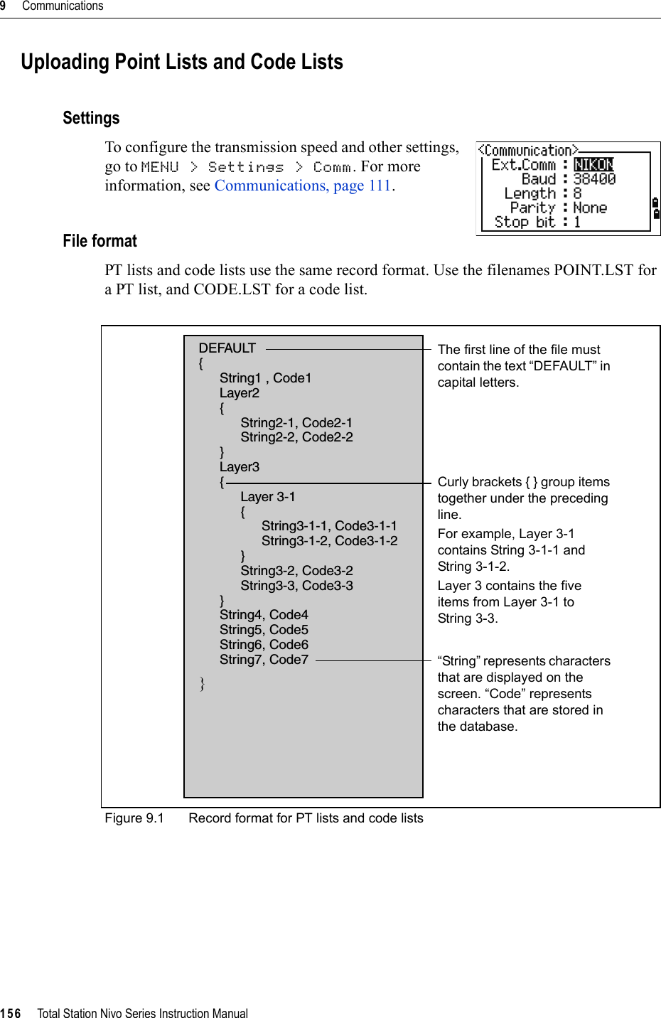
![Total Station Nivo Series Instruction Manual 171Error Messages 10DataCan't Edit Current ST 100.8You have tried to edit the current ST.Note – You cannot edit the current ST. However, old ST records can be edited. No recalculation can be performed on the instrument.Press any key to return to the code/layer name input screen.Can't Edit ST/BS refer to this PT 100.9You have tried to edit a coordinate that the current ST or BS refers to. You cannot change a coordinate if the current ST or BS refers to it.Press any key to return to the Data view screen.Can't Edit XYZ from measurement 100.10You have tried to change the coordinates of an SO, SS, or CP record. You cannot change the coordinates of an SO, SS, or CP record. Press any key to return to the previous screen.DELETE Stn-XYZ 100.11You have tried to delete a coordinate record that the current ST or BS refers to. You must confirm that you want to delete a coordinate record that the current ST or BS refers to.To ... Press ...delete XYZ the DEL softkeyreturn to the previous screen without deleting XYZ [ESC] or the Abrt softkey](https://usermanual.wiki/NIKON-TRIMBLE/NT0001.Host-2-user-manual-3-of-3/User-Guide-1089795-Page-81.png)
![10 Error Messages172 Total Station Nivo Series Instruction ManualJob ManagerCannot Assign 100.12You have tried to set the current job as the control file.Press any key to return to the previous screen. Then select a different job.Can't Create 100.13There is no space available to create a job or record a point.Press any key to return to the Job Manager. Then use the DEL softkey to delete old jobs.Existing Job 100.14You have entered an existing job name for a new job.Press any key and then change the name for the new job.MAX 32Jobs 100.15You are trying to create a new job when the maximum number of jobs (32) is already stored.Press any key to return to the Job Manager. Then use the DEL softkey to delete old jobs.ProgramsNO Stn Setup 100.16You did not perform a station setup or BS check before entering the Programs function.BTip – Selecting Continue does not resume the last ST record. You should only use the Continue option if you are sure that the previous ST coordinates and the current HA orientation are correct. Otherwise, records in the Programs function may not be correct.XY&Z coordinate are required 100.17Three-dimensional coordinates are required in S-Plane function.Press any key to return to the point input screen. Then enter a three-dimensional point.To ... Press ...go to the Stn Setup menu [2] or select Stn Setupreturn to the BMS [ESC]go to the Programs menu [1] or select Continue](https://usermanual.wiki/NIKON-TRIMBLE/NT0001.Host-2-user-manual-3-of-3/User-Guide-1089795-Page-82.png)
![Total Station Nivo Series Instruction Manual 173Error Messages 10Recording DataDATA FULL 100.18The data storage is full.Press any key to return to the Basic Measurement Screen (BMS). Then:DUPLICATE PT 100.19The input PT you are trying to record already exists in the current job. An existing coordinate record cannot be overwritten by measured data.Press any key to return to the point input screen. Change PT.Duplicate PT 100.20The input PT you are trying to record already exists in the current job as an SS, SO, or CP record. An existing SS, SO, or CP record can be overwritten by measured data.No Open Job 100.21No job is open.NO Stn Setup 100.22There is no station record in the current job, or a station setup or BS check has not been done since the program was rebooted.To ... Go to ...delete unnecessary data MENU > Datadelete jobs MENU > JobTo ... Press ...return to the PT input screen [ESC] or the Abrt softkeyrecord RAW data and update XYZ data the XYZ softkeyrecord RAW data only the RAW softkeyTo ... Press ...open the job list, if there are existing jobs [1] or select Select jobcreate a new job [2] or select Create jobreturn to the previous screen [ESC]To ... Press ...continue recording [1] or select Continue. If there is already an ST record in the job, the message CO, Use current orientationappears.go to the Stn Setup menu [2] or select STN Setupreturn to the previous screen [ESC]](https://usermanual.wiki/NIKON-TRIMBLE/NT0001.Host-2-user-manual-3-of-3/User-Guide-1089795-Page-83.png)
![10 Error Messages174 Total Station Nivo Series Instruction ManualOVER RANGE 100.23You are trying to record a coordinate with more than 13 digitsPress any key to return to the previous screen. Then check the current ST coordinate.SearchingPT Not Found 100.24There is no point that matches the criteria you entered.Press any key to return to the point input screen.This message may appear in any function where the PT/CD is input, such as Station Setup or Stakeout.SettingsJob Settings will be changed 100.25You have changed one or more of the following job settings:•VA zero or HA in the Angle screen (see Angle, page 108)•Scale, T-P, Sea Lvl, or C&R in the Distance screen (see Distance, page 109)•Coord or Az Zero in the Coordinates screen (see Coordinate, page 110)•Angle, Dist, Temp, or Press in the Unit screen (see Unit, page 111)Note – To record a point using the new settings, create a new job using the new settings.StakeoutInput Error 100.26The point name style used in the Fr field is not the same as the style used in the To field. For example, the Fr field style is 1, and the To field style is A200.Press any key to return to the Fr/To input screen. Then re-enter the point name, using the same naming style in both fields.To ... Press ...discard the changes to the job settings [ESC] or the Abrt softkey. The current job remains open.close the current job and save the changes to the job settings[ENT] or the OK softkey](https://usermanual.wiki/NIKON-TRIMBLE/NT0001.Host-2-user-manual-3-of-3/User-Guide-1089795-Page-84.png)
![Total Station Nivo Series Instruction Manual 175Error Messages 10NO Stn Setup 100.27You did not perform a station setup or BS check before entering the Stakeout function.BTip – Selecting Continue does not resume the last ST record. You should only use the Continue option if you are sure that the previous ST coordinates and the current HA orientation are correct. Otherwise, records in the Stakeout function may not be correct.Station SetupCalc ST Failed Need additional PT 100.28Calculating ST failed in resection. This message may appear after you have deleted a point the View shots screen.Press any key to return to the PT input screen. Take another shot to calculate the ST coordinate.Same Coordinate 100.29The input PT or coordinate is identical to the current station in STN/1:Known, or the same coordinate or point name/number is found in Resection.Press any key to return to the PT input screen. Then use a different PT.Space LOW 100.30There is not enough space to record a station when you start any of the Station Setup functions.XY-coordinate is required 100.31The input point for ST/BS does not have N/E coordinates.Press any key to return to the PT input screen. Then use a PT that has N/E coordinates.To... Press ...go to the Stn Setup menu [2] or select Stn Setupreturn to the Basic Measurement Screen (BMS)[ESC]go to the Stakeout menu [1] or select ContinueTo ... Press ...return to the BMS press [ESC] or the Abrt softkey. Use the DELsoftkey in Job Manager to delete old jobs.continue press [ENT] or the OK softkey. You may not be able to record the whole process.](https://usermanual.wiki/NIKON-TRIMBLE/NT0001.Host-2-user-manual-3-of-3/User-Guide-1089795-Page-85.png)