NIKON TRIMBLE NT0001 Bluetooth module User Manual TS635 manual 1
NIKON-TRIMBLE CO., LTD. Bluetooth module TS635 manual 1
Contents
Host 3 user manual 1 of 2

Trimble® TS635 Construction
Total Station
USER GUIDE
Part 1

NORTH AMERICA
Trimble Construction Division
5475 Kellenburger Road
Dayton, Ohio 45424
USA
800-538-7800 (Toll Free)
+1-937-245-5154 Phone
+1-937-233-9441 Fax
EUROPE
Trimble GmbH
Am Prime Parc 11
65479 Raunheim
GERMANY
+49-6142-2100-0 Phone
+49-6142-2100-550 Fax
ASIA-PACIFIC
Trimble Navigation
Singapore Pty Limited
80 Marine Parade Road
#22-06, Parkway Parade
Singapore 449269
SINGAPORE
+65-6348-2212 Phone
+65-6348-2232 Fax
www.trimble.com
Version 1.00
Revision A
February 2009
USER GUIDE
Trimble® TS635 Construction
Total Station
2 Trimble TS635 Construction Total Station User Guide
Corporate Office
Construction Division
5475 Kellenburger Road
Dayton, Ohio 45424-1099
USA
800-538-7800 (toll free in USA)
+1-937-245-5600 Phone
+1-937-233-9004 Fax
www.trimble.com
Legal Notices
Copyright and Trademarks
© 2006-2009, Nikon-Trimble Co. Limited. All rights reserved.
© 2007-2009, Trimble Navigation Limited. All rights reserved.
Trimble and the Globe & Triangle logo are trademarks of Trimble
Navigation Limited registered in the United States and in other
countries. Nikon is a registered trademark of the Nikon Corporation.
All other trademarks are the property of their respective owners.
Release Notice
This is the February 2009 release (Revision A) of the Trimble TS635
Construction Total Station User Guide. It applies to version 1.00 of the
TS635 construction total station.
Manufacturer
Nikon-Trimble Co., Ltd.
Technoport Mituiseimei Bldg.
16-2, Minamikamata 2-chome, Ota-ku
Tokyo 144-0035 Japan
Product Limited Warranty Information
For applicable product Limited Warranty information, please refer to the
Limited Warranty Card included with this Trimble product, or consult
your local Trimble authorized dealer.
Notices
Class B Statement – Notice to Users. This equipment has been tested
and found to comply with the limits for a Class B digital device, pursuant
to Part 15 of the FCC rules. These limits are designed to provide
reasonable protection against harmful interference in a residential
installation. This equipment generates, uses, and can radiate radio
frequency energy and, if not installed and used in accordance with the
instructions, may cause harmful interference to radio communication.
However, there is no guarantee that interference will not occur in a
particular installation. If this equipment does cause harmful
interference to radio or television reception, which can be determined
by turning the equipment off and on, the user is encouraged to try to
correct the interference by one or more of the following measures:
– Reorient or relocate the receiving antenna.
– Increase the separation between the equipment and the receiver.
– Connect the equipment into an outlet on a circuit different from that
to which the receiver is connected.
– Consult the dealer or an experienced radio/TV technician for help.
Changes and modifications not expressly approved by the manufacturer
or registrant of this equipment can void your authority to operate this
equipment under Federal Communications Commission rules.
CWARNING - This equipment has been certified to comply with the
limits for a Class B personal computer and peripherals, pursuant to
Subpart B of Part 15 of FCC Rules. Only peripherals (computer
input/output devices, terminals, printers, etc.) certified to comply with
the Class B limits may be attached to this equipment. Operation with
non-certified personal computer and/or peripherals is likely to result in
interference to radio and TV reception. The connection of a non-
shielded equipment interface cable to this equipment will invalidate
the FCC Certification of this device and may cause interference levels
which exceed the limits established by the FCC for this equipment.
You are cautioned that changes or modifications not expressly
approved by the party responsible for compliance could void your
authority to operate the equipment.
Canada
This digital apparatus does not exceed the Class B limits for radio noise
emissions from digital apparatus as set out in the radio interference
regulations of the Canadian Department of Communications.
Le présent appareil numérique n’émet pas de bruits radioélectriques
dépassant les limites applicables aux appareils numériques de Classe B
prescrites dans le règlement sur le brouillage radioélectrique édicté par
le Ministère des Communications du Canada.
Europe
This product has been tested and found to comply with the
requirements for a Class B device pursuant to European
Council Directive 2004/108/EC on EMC, thereby satisfying the
requirements for CE Marking and sale within the European Economic
Area (EEA). These requirements are designed to provide reasonable
protection against harmful interference when the equipment is operated
in a residential or commercial environment.
Representative in Europe
Trimble GmbH
Am Prime Parc 11
65479 Raunheim, Germany
Australia and New Zealand
This product conforms with the regulatory requirements of the
Australian Communications Authority (ACA) EMC framework,
thus satisfying the requirements for C-Tick Marking and sale
within Australia and New Zealand.
Taiwan Battery Recycling Requirements
The product contains a removable Ni-MH battery.
Taiwanese regulations require that waste batteries are
recycled.
Notice to Our European Union Customers
For product recycling instructions and more information, please
go to: www.trimble.com/environment/summary.html.
Recycling in Europe
To recycle Trimble WEEE, call: +31 497 53 2430, and ask for the
"WEEE associate," or mail a request for recycling instructions to:
Trimble Europe BV
c/o Menlo Worldwide Logistics
Meerheide 45
5521 DZ Eersel, NL
For the Bluetooth unit
USA
FCC Part 15 Subpart/RSS-210, OET bulletin 65 supplement C satisfied
CAUTION: Any changes or modifications not expressly approved by the
party responsible for compliance could void the user's authority to
operate the equipment.
NOTE: This equipment has been tested and found to comply with the limits
for a Class B digital device, pursuant to part 15 of the FCC Rules. These
limits are designed to provide reasonable protection against harmful
interference in a residential installation. This equipment generates, uses
and can radiate radio frequency energy and, if not installed and used in
accordance with the instructions, may cause harmful interference to radio
communications. However, there is no guarantee that interference will not
occur in a particular installation. If this equipment does cause harmful
interference to radio or television reception, which can be determined by
turning the equipment off and on, the user is encouraged to try to correct
the interference by one or more of the following measures:
-Reorient or relocate the receiving antenna.
-Increase the separation between the equipment and receiver.
-Connect the equipment into an outlet on a circuit different from that to
which the
receiver is connected.
-Consult the dealer or an experienced radio/TV technician for help.
Canada
RSS-210 Low Power Device
Operation is subject to the following two conditions: (1) This device may
not cause interference, and (2) this device must accept any interference,
including interference that may cause undesired operation of the device.
European Union countries, Iceland, Norway, Liechtenstein, Turkey,
Switzerland
EN300 328v17.1, EN50360 satisfied
Hereby, Nikon-Trimble Co., Ltd., declares that this instrument is in
compliance with the essential requirements and other relevant
provisions of Directive 1999/5/EC.
Declaration of Conformity available at http://www.nikon-trimble.com/.
RF exposure compliance
1. To comply with FCC/IC RF exposure compliance requirements, a
separation distance of at least 20 cm must be maintained between the
antenna of this device and all persons.
2. This transmitter must not be co-located or operated in conjunction
with any other antenna or transmitter.
Trimble TS635 Construction Total Station User Guide 3
Contents 1
Safety . . . . . . . . . . . . . . . . . . . . . . . . . . . . . . . . . . . . . . . . 7
Warnings and Cautions . . . . . . . . . . . . . . . . . . . . . . . . . . . . . . . . . . . . . . . . . . . . . . 7
Rechargeable Lithium-ion (Li-ion) batteries . . . . . . . . . . . . . . . . . . . . . . . . . . . . . 7
Warnings . . . . . . . . . . . . . . . . . . . . . . . . . . . . . . . . . . . . . . . . . . . . . . . . . . . 8
Cautions . . . . . . . . . . . . . . . . . . . . . . . . . . . . . . . . . . . . . . . . . . . . . . . . . . . 9
Laser safety . . . . . . . . . . . . . . . . . . . . . . . . . . . . . . . . . . . . . . . . . . . . . . . . . . . . . 10
Specifications for laser emission . . . . . . . . . . . . . . . . . . . . . . . . . . . . . . . . . . . 10
Conforming standards . . . . . . . . . . . . . . . . . . . . . . . . . . . . . . . . . . . . . . . . . 11
Labels . . . . . . . . . . . . . . . . . . . . . . . . . . . . . . . . . . . . . . . . . . . . . . . . . . . . 11
1 Introduction . . . . . . . . . . . . . . . . . . . . . . . . . . . . . . . . . . . 13
System diagram . . . . . . . . . . . . . . . . . . . . . . . . . . . . . . . . . . . . . . . . . . . . . . . . . . 14
Care and maintenance. . . . . . . . . . . . . . . . . . . . . . . . . . . . . . . . . . . . . . . . . . . . . . 15
Storage . . . . . . . . . . . . . . . . . . . . . . . . . . . . . . . . . . . . . . . . . . . . . . . . . . . 15
Environmental conditions . . . . . . . . . . . . . . . . . . . . . . . . . . . . . . . . . . . . . . . 15
Cleaning . . . . . . . . . . . . . . . . . . . . . . . . . . . . . . . . . . . . . . . . . . . . . . . . . . 16
Adjusting and tightening . . . . . . . . . . . . . . . . . . . . . . . . . . . . . . . . . . . . . . . . 16
Related information . . . . . . . . . . . . . . . . . . . . . . . . . . . . . . . . . . . . . . . . . . . . . . . 17
2 Setting up the Instrument . . . . . . . . . . . . . . . . . . . . . . . . . . . 19
Unpacking and repacking the instrument . . . . . . . . . . . . . . . . . . . . . . . . . . . . . . . . . 20
Charging the battery pack . . . . . . . . . . . . . . . . . . . . . . . . . . . . . . . . . . . . . . . . . . . 20
Applying power . . . . . . . . . . . . . . . . . . . . . . . . . . . . . . . . . . . . . . . . . . . . . . 22
Charging the battery. . . . . . . . . . . . . . . . . . . . . . . . . . . . . . . . . . . . . . . . . . . 22
Conditioning / calibrating a battery . . . . . . . . . . . . . . . . . . . . . . . . . . . . . . . . . 23
Detaching the battery pack . . . . . . . . . . . . . . . . . . . . . . . . . . . . . . . . . . . . . . 23
Attaching the battery pack . . . . . . . . . . . . . . . . . . . . . . . . . . . . . . . . . . . . . . . 24
Setting up the tripod . . . . . . . . . . . . . . . . . . . . . . . . . . . . . . . . . . . . . . . . . . . . . . . 25
Centering the instrument . . . . . . . . . . . . . . . . . . . . . . . . . . . . . . . . . . . . . . . . . . . . 26
Centering with the optical plummet. . . . . . . . . . . . . . . . . . . . . . . . . . . . . . . . . 26
Centering with the laser plummet . . . . . . . . . . . . . . . . . . . . . . . . . . . . . . . . . . 26
Centering with a plumb bob . . . . . . . . . . . . . . . . . . . . . . . . . . . . . . . . . . . . . . 27
Leveling the instrument . . . . . . . . . . . . . . . . . . . . . . . . . . . . . . . . . . . . . . . . . . . . . 28
Focusing the telescope. . . . . . . . . . . . . . . . . . . . . . . . . . . . . . . . . . . . . . . . . . . . . . 29
Setting the measurement mode and preparing the target . . . . . . . . . . . . . . . . . . . . . . . 30
Measurement with a prism. . . . . . . . . . . . . . . . . . . . . . . . . . . . . . . . . . . . . . . 30
Measurement in reflectorless (N-Prism) mode . . . . . . . . . . . . . . . . . . . . . . . . . . 31
Viewing and changing the measurement settings. . . . . . . . . . . . . . . . . . . . . . . . . . . . . 32
Target field . . . . . . . . . . . . . . . . . . . . . . . . . . . . . . . . . . . . . . . . . . . . . . . . . 32
Prism constant . . . . . . . . . . . . . . . . . . . . . . . . . . . . . . . . . . . . . . . . . . . . . . 32
3 Getting Started. . . . . . . . . . . . . . . . . . . . . . . . . . . . . . . . . . 33
Instrument keyboard and display . . . . . . . . . . . . . . . . . . . . . . . . . . . . . . . . . . . . . . 36
Instrument keyboard . . . . . . . . . . . . . . . . . . . . . . . . . . . . . . . . . . . . . . . . . . 36
Status bar. . . . . . . . . . . . . . . . . . . . . . . . . . . . . . . . . . . . . . . . . . . . . . . . . . 37

4 Trimble TS635 Construction Total Station User Guide
LCD backlight, laser pointer, beep sound, and contrast adjustment . . . . . . . . . . . . . 39
[DSP] button. . . . . . . . . . . . . . . . . . . . . . . . . . . . . . . . . . . . . . . . . . . . . . . . 40
[MODE] button . . . . . . . . . . . . . . . . . . . . . . . . . . . . . . . . . . . . . . . . . . . . . . 41
[HOT] key . . . . . . . . . . . . . . . . . . . . . . . . . . . . . . . . . . . . . . . . . . . . . . . . . 42
Bubble indicator . . . . . . . . . . . . . . . . . . . . . . . . . . . . . . . . . . . . . . . . . . . . . 42
Laser plummet . . . . . . . . . . . . . . . . . . . . . . . . . . . . . . . . . . . . . . . . . . . . . . 43
Turning on the instrument . . . . . . . . . . . . . . . . . . . . . . . . . . . . . . . . . . . . . . . . . . . 44
Turning off the instrument . . . . . . . . . . . . . . . . . . . . . . . . . . . . . . . . . . . . . . . . . . . 44
Sleep mode. . . . . . . . . . . . . . . . . . . . . . . . . . . . . . . . . . . . . . . . . . . . . . . . . 44
Regional configuration. . . . . . . . . . . . . . . . . . . . . . . . . . . . . . . . . . . . . . . . . . . . . . 45
List available jobs or data . . . . . . . . . . . . . . . . . . . . . . . . . . . . . . . . . . . . . . . . . . . . 46
Entering data. . . . . . . . . . . . . . . . . . . . . . . . . . . . . . . . . . . . . . . . . . . . . . . . . . . . 46
Entering a point name or number . . . . . . . . . . . . . . . . . . . . . . . . . . . . . . . . . . 46
Entering a code . . . . . . . . . . . . . . . . . . . . . . . . . . . . . . . . . . . . . . . . . . . . . . 49
Entering values in feet and inches . . . . . . . . . . . . . . . . . . . . . . . . . . . . . . . . . . 51
Creating or opening a job . . . . . . . . . . . . . . . . . . . . . . . . . . . . . . . . . . . . . . . . . . . . 51
Creating a new job . . . . . . . . . . . . . . . . . . . . . . . . . . . . . . . . . . . . . . . . . . . . 52
Creating a control job . . . . . . . . . . . . . . . . . . . . . . . . . . . . . . . . . . . . . . . . . . 52
Measuring distances . . . . . . . . . . . . . . . . . . . . . . . . . . . . . . . . . . . . . . . . . . . . . . . 53
Sighting a prism reflector. . . . . . . . . . . . . . . . . . . . . . . . . . . . . . . . . . . . . . . . 53
Taking a distance measurement . . . . . . . . . . . . . . . . . . . . . . . . . . . . . . . . . . . 53
Viewing and changing the measurement settings . . . . . . . . . . . . . . . . . . . . . . . . 54
4 Applications . . . . . . . . . . . . . . . . . . . . . . . . . . . . . . . . . . . 55
HA reset and angle operations. . . . . . . . . . . . . . . . . . . . . . . . . . . . . . . . . . . . . . . . . 56
Setting the horizontal angle to 0 . . . . . . . . . . . . . . . . . . . . . . . . . . . . . . . . . . . 56
Entering the horizontal angle . . . . . . . . . . . . . . . . . . . . . . . . . . . . . . . . . . . . . 56
Station setup . . . . . . . . . . . . . . . . . . . . . . . . . . . . . . . . . . . . . . . . . . . . . . . . . . . . 56
Baseline . . . . . . . . . . . . . . . . . . . . . . . . . . . . . . . . . . . . . . . . . . . . . . . . . . . 57
Known. . . . . . . . . . . . . . . . . . . . . . . . . . . . . . . . . . . . . . . . . . . . . . . . . . . . 58
Base XYZ . . . . . . . . . . . . . . . . . . . . . . . . . . . . . . . . . . . . . . . . . . . . . . . . . . 60
Remote BM . . . . . . . . . . . . . . . . . . . . . . . . . . . . . . . . . . . . . . . . . . . . . . . . 60
BS Check . . . . . . . . . . . . . . . . . . . . . . . . . . . . . . . . . . . . . . . . . . . . . . . . . . 61
Layout menu . . . . . . . . . . . . . . . . . . . . . . . . . . . . . . . . . . . . . . . . . . . . . . . . . . . . 62
L-O to Point . . . . . . . . . . . . . . . . . . . . . . . . . . . . . . . . . . . . . . . . . . . . . . . . 62
L-O from Line . . . . . . . . . . . . . . . . . . . . . . . . . . . . . . . . . . . . . . . . . . . . . . . 63
L-O from Arc. . . . . . . . . . . . . . . . . . . . . . . . . . . . . . . . . . . . . . . . . . . . . . . . 64
XYZ . . . . . . . . . . . . . . . . . . . . . . . . . . . . . . . . . . . . . . . . . . . . . . . . . . . . . 65
Programs menu . . . . . . . . . . . . . . . . . . . . . . . . . . . . . . . . . . . . . . . . . . . . . . . . . . 67
Remote distance measurement (RDM) - overview . . . . . . . . . . . . . . . . . . . . . . . . 68
RDM (Radial) . . . . . . . . . . . . . . . . . . . . . . . . . . . . . . . . . . . . . . . . . . . . . . . 69
RDM (Cont) . . . . . . . . . . . . . . . . . . . . . . . . . . . . . . . . . . . . . . . . . . . . . . . . 69
REM . . . . . . . . . . . . . . . . . . . . . . . . . . . . . . . . . . . . . . . . . . . . . . . . . . . . . 70
V-Plane . . . . . . . . . . . . . . . . . . . . . . . . . . . . . . . . . . . . . . . . . . . . . . . . . . . 70
Cogo . . . . . . . . . . . . . . . . . . . . . . . . . . . . . . . . . . . . . . . . . . . . . . . . . . . . . 71
Recording measurement data . . . . . . . . . . . . . . . . . . . . . . . . . . . . . . . . . . . . . . . . . 83

Trimble TS635 Construction Total Station User Guide 5
Switching between display screens . . . . . . . . . . . . . . . . . . . . . . . . . . . . . . . . . . . . . . 83
5 Menu Screen . . . . . . . . . . . . . . . . . . . . . . . . . . . . . . . . . . . 85
Job . . . . . . . . . . . . . . . . . . . . . . . . . . . . . . . . . . . . . . . . . . . . . . . . . . . . . . . . . . 86
Opening an existing job . . . . . . . . . . . . . . . . . . . . . . . . . . . . . . . . . . . . . . . . . 86
Creating a new job . . . . . . . . . . . . . . . . . . . . . . . . . . . . . . . . . . . . . . . . . . . . 86
Deleting a job . . . . . . . . . . . . . . . . . . . . . . . . . . . . . . . . . . . . . . . . . . . . . . . 88
Setting the control job. . . . . . . . . . . . . . . . . . . . . . . . . . . . . . . . . . . . . . . . . . 89
Displaying job information. . . . . . . . . . . . . . . . . . . . . . . . . . . . . . . . . . . . . . . 89
Settings (basic job settings). . . . . . . . . . . . . . . . . . . . . . . . . . . . . . . . . . . . . . . . . . . 90
Angle . . . . . . . . . . . . . . . . . . . . . . . . . . . . . . . . . . . . . . . . . . . . . . . . . . . . 90
Distance . . . . . . . . . . . . . . . . . . . . . . . . . . . . . . . . . . . . . . . . . . . . . . . . . . 90
Coordinate . . . . . . . . . . . . . . . . . . . . . . . . . . . . . . . . . . . . . . . . . . . . . . . . . 93
Communications . . . . . . . . . . . . . . . . . . . . . . . . . . . . . . . . . . . . . . . . . . . . . 93
Unit . . . . . . . . . . . . . . . . . . . . . . . . . . . . . . . . . . . . . . . . . . . . . . . . . . . . . 93
Power saving. . . . . . . . . . . . . . . . . . . . . . . . . . . . . . . . . . . . . . . . . . . . . . . . 94
Recording. . . . . . . . . . . . . . . . . . . . . . . . . . . . . . . . . . . . . . . . . . . . . . . . . . 94
Other settings . . . . . . . . . . . . . . . . . . . . . . . . . . . . . . . . . . . . . . . . . . . . . . . 94
Data . . . . . . . . . . . . . . . . . . . . . . . . . . . . . . . . . . . . . . . . . . . . . . . . . . . . . . . . . 95
Viewing coordinate data . . . . . . . . . . . . . . . . . . . . . . . . . . . . . . . . . . . . . . . . 95
UP, MP, CC, SS, and SO records . . . . . . . . . . . . . . . . . . . . . . . . . . . . . . . . . . . . 96
Deleting coordinate records . . . . . . . . . . . . . . . . . . . . . . . . . . . . . . . . . . . . . . 96
Editing coordinate records . . . . . . . . . . . . . . . . . . . . . . . . . . . . . . . . . . . . . . . 96
Searching coordinate records . . . . . . . . . . . . . . . . . . . . . . . . . . . . . . . . . . . . . 97
Entering coordinates . . . . . . . . . . . . . . . . . . . . . . . . . . . . . . . . . . . . . . . . . . 98
Communication . . . . . . . . . . . . . . . . . . . . . . . . . . . . . . . . . . . . . . . . . . . . . . . . . . 99
Downloading coordinate data. . . . . . . . . . . . . . . . . . . . . . . . . . . . . . . . . . . . . 99
Uploading coordinate data . . . . . . . . . . . . . . . . . . . . . . . . . . . . . . . . . . . . . . . 99
1sec-Key. . . . . . . . . . . . . . . . . . . . . . . . . . . . . . . . . . . . . . . . . . . . . . . . . . . . . . .101
[MSR] button settings . . . . . . . . . . . . . . . . . . . . . . . . . . . . . . . . . . . . . . . . . .101
[DSP] button settings . . . . . . . . . . . . . . . . . . . . . . . . . . . . . . . . . . . . . . . . . .101
Calibration . . . . . . . . . . . . . . . . . . . . . . . . . . . . . . . . . . . . . . . . . . . . . . . . . . . . .102
Time . . . . . . . . . . . . . . . . . . . . . . . . . . . . . . . . . . . . . . . . . . . . . . . . . . . . . . . . .102
6 Checking and Adjusting . . . . . . . . . . . . . . . . . . . . . . . . . . . . 103
Adjusting the electronic level . . . . . . . . . . . . . . . . . . . . . . . . . . . . . . . . . . . . . . . . .104
Checking and adjusting the circular level . . . . . . . . . . . . . . . . . . . . . . . . . . . . . . . . . .104
Checking and adjusting the optical/laser plummet. . . . . . . . . . . . . . . . . . . . . . . . . . . .104
Zero point errors of vertical scale and horizontal angle corrections . . . . . . . . . . . . . . . . .105
Checking the calibration . . . . . . . . . . . . . . . . . . . . . . . . . . . . . . . . . . . . . . . .105
Adjusting the calibration . . . . . . . . . . . . . . . . . . . . . . . . . . . . . . . . . . . . . . . .106
The instrument constant . . . . . . . . . . . . . . . . . . . . . . . . . . . . . . . . . . . . . . . . . . . .107
Checking and adjusting the laser pointer . . . . . . . . . . . . . . . . . . . . . . . . . . . . . . . . . .108
A Specifications. . . . . . . . . . . . . . . . . . . . . . . . . . . . . . . . . . 109
Main body. . . . . . . . . . . . . . . . . . . . . . . . . . . . . . . . . . . . . . . . . . . . . . . . . . . . . .110

6 Trimble TS635 Construction Total Station User Guide
Telescope . . . . . . . . . . . . . . . . . . . . . . . . . . . . . . . . . . . . . . . . . . . . . . . . . .110
Measurement range . . . . . . . . . . . . . . . . . . . . . . . . . . . . . . . . . . . . . . . . . . .110
Distance precision . . . . . . . . . . . . . . . . . . . . . . . . . . . . . . . . . . . . . . . . . . . .111
Measurement intervals . . . . . . . . . . . . . . . . . . . . . . . . . . . . . . . . . . . . . . . . .111
Angle measurement . . . . . . . . . . . . . . . . . . . . . . . . . . . . . . . . . . . . . . . . . . .112
Tilt sensor . . . . . . . . . . . . . . . . . . . . . . . . . . . . . . . . . . . . . . . . . . . . . . . . .112
Tangent screws . . . . . . . . . . . . . . . . . . . . . . . . . . . . . . . . . . . . . . . . . . . . . .112
Tribrach. . . . . . . . . . . . . . . . . . . . . . . . . . . . . . . . . . . . . . . . . . . . . . . . . . .112
Level . . . . . . . . . . . . . . . . . . . . . . . . . . . . . . . . . . . . . . . . . . . . . . . . . . . . .112
Optical plumment (Optional) . . . . . . . . . . . . . . . . . . . . . . . . . . . . . . . . . . . . .112
Laser plummet . . . . . . . . . . . . . . . . . . . . . . . . . . . . . . . . . . . . . . . . . . . . . .113
Display and keypad . . . . . . . . . . . . . . . . . . . . . . . . . . . . . . . . . . . . . . . . . . .113
Connections in the base of instrument . . . . . . . . . . . . . . . . . . . . . . . . . . . . . . .113
Battery pack . . . . . . . . . . . . . . . . . . . . . . . . . . . . . . . . . . . . . . . . . . . . . . . .113
Environmental performance. . . . . . . . . . . . . . . . . . . . . . . . . . . . . . . . . . . . . .114
Dimensions . . . . . . . . . . . . . . . . . . . . . . . . . . . . . . . . . . . . . . . . . . . . . . . .114
Weight. . . . . . . . . . . . . . . . . . . . . . . . . . . . . . . . . . . . . . . . . . . . . . . . . . . .114
Environmental protection . . . . . . . . . . . . . . . . . . . . . . . . . . . . . . . . . . . . . . .114
Standard components . . . . . . . . . . . . . . . . . . . . . . . . . . . . . . . . . . . . . . . . . . . . . .114
External device connector . . . . . . . . . . . . . . . . . . . . . . . . . . . . . . . . . . . . . . . . . . .115
B Transferring Coordinate Data . . . . . . . . . . . . . . . . . . . . . . . . 117
Transferring coordinate data to the total station . . . . . . . . . . . . . . . . . . . . . . . . . . . . .118
Settings . . . . . . . . . . . . . . . . . . . . . . . . . . . . . . . . . . . . . . . . . . . . . . . . . . .118
Record format . . . . . . . . . . . . . . . . . . . . . . . . . . . . . . . . . . . . . . . . . . . . . . .118
Data example . . . . . . . . . . . . . . . . . . . . . . . . . . . . . . . . . . . . . . . . . . . . . . .119
Transferring coordinate data from the total station . . . . . . . . . . . . . . . . . . . . . . . . . . .119
Settings . . . . . . . . . . . . . . . . . . . . . . . . . . . . . . . . . . . . . . . . . . . . . . . . . . .119
Data examples. . . . . . . . . . . . . . . . . . . . . . . . . . . . . . . . . . . . . . . . . . . . . . .119
C Error Messages . . . . . . . . . . . . . . . . . . . . . . . . . . . . . . . . . 121
Cogo . . . . . . . . . . . . . . . . . . . . . . . . . . . . . . . . . . . . . . . . . . . . . . . . . . . . . . . . .122
Communications . . . . . . . . . . . . . . . . . . . . . . . . . . . . . . . . . . . . . . . . . . . . . . . . .122
Data . . . . . . . . . . . . . . . . . . . . . . . . . . . . . . . . . . . . . . . . . . . . . . . . . . . . . . . . .123
Job manager . . . . . . . . . . . . . . . . . . . . . . . . . . . . . . . . . . . . . . . . . . . . . . . . . . . .123
Layout . . . . . . . . . . . . . . . . . . . . . . . . . . . . . . . . . . . . . . . . . . . . . . . . . . . . . . . .124
Programs . . . . . . . . . . . . . . . . . . . . . . . . . . . . . . . . . . . . . . . . . . . . . . . . . . . . . .124
Recording data. . . . . . . . . . . . . . . . . . . . . . . . . . . . . . . . . . . . . . . . . . . . . . . . . . .125
Searching . . . . . . . . . . . . . . . . . . . . . . . . . . . . . . . . . . . . . . . . . . . . . . . . . . . . . .126
Settings . . . . . . . . . . . . . . . . . . . . . . . . . . . . . . . . . . . . . . . . . . . . . . . . . . . . . . .126
Station setup . . . . . . . . . . . . . . . . . . . . . . . . . . . . . . . . . . . . . . . . . . . . . . . . . . . .127
System error . . . . . . . . . . . . . . . . . . . . . . . . . . . . . . . . . . . . . . . . . . . . . . . . . . . .127

Trimble TS635 Construction Total Station User Guide 7
Safety
For your safety read the safety and warnings section and this manual carefully and
thoroughly before using the Trimble® TS635 construction total station.
Although these products are designed for maximum safety, using them incorrectly or
disregarding the instructions can cause personal injury or property damage.
You should also read the installation manual for the battery charger, and the
documentation for any other equipment that you use with a Trimble TS635
construction total station.
Note – Always keep this user guide near the instrument for easy reference.
Warnings and Cautions
The following conventions are used to indicate safety instructions:
CWARNING – Warnings alert you to situations that could cause death or serious injury.
CCAUTION – Cautions alert you to situations that could cause injury or property damage.
Always read and follow the instructions carefully.
Rechargeable Lithium-ion (Li-ion) batteries
WARNING – Do not damage the rechargeable Lithium-ion battery. A damaged battery
can cause an explosion or fire, and can result in personal injury and/or property damage.
To prevent injury or damage:
– Do not use or charge the battery if it appears to be damaged. Signs of damage include,
but are not limited to, discoloration, warping, and leaking battery fluid.
– Do not expose the battery to fire, high temperature, or direct sunlight.
– Do not immerse the battery in water.
– Do not use or store the battery inside a vehicle during hot weather.
– Do not drop or puncture the battery.
– Do not open the battery or short-circuit its contacts.
CWARNING – Avoid contact with the rechargeable Lithium-ion battery if it appears to be
leaking. Battery fluid is corrosive, and contact with it can result in personal injury and/or
property damage.
To prevent injury or damage:
– If the battery leaks, avoid contact with the battery fluid.
– If battery fluid gets into your eyes, immediately rinse your eyes with clean water and
seek medical attention. Do not rub your eyes!
– If battery fluid gets onto your skin or clothing, immediately use clean water to wash off
the battery fluid.

Safety
8 Trimble TS635 Construction Total Station User Guide
CCharge and use the rechargeable Lithium-ion battery only in strict accordance with the
instructions. Charging or using the battery in unauthorized equipment can cause an
explosion or fire, and can result in personal injury and/or equipment damage.
To prevent injury or damage:
– Do not charge or use the battery if it appears to be damaged or leaking.
– Charge the Lithium-ion battery only in a product that is specified to charge it. Be sure to
follow all instructions that are provided with the battery charger.
– Discontinue charging a battery that gives off extreme heat or a burning odor.
– Use the battery only in equipment that is specified to use it.
– Use the battery only for its intended use and according to the instructions in the product
documentation.
Warnings
Before using the instrument, read the following warnings and follow the instructions
that they provide.
CWARNING – Never look at the sun through the telescope. If you do, you may damage or
lose your eyesight.
CWARNING – The TS635 construction total station is not designed to be explosion-proof.
Do not use the instrument in coal mines, in areas contaminated with coal dust, or near
other flammable substances.
CWARNING – Never disassemble, modify, or repair the instrument yourself. If you do, you
may receive electric shocks or burns, or the instrument may catch fire. You may also impair
the accuracy of the instrument.
CWARNING – Use only the specified battery charger and AC adapter that is supplied with
the instrument. Do not use any other charger or you may cause the battery pack to catch
fire or rupture.
CWARNING – Do not cover the battery charger and AC adapter while the battery pack is
being recharged. The charger must be able to dissipate heat adequately. Coverings such
as blankets or clothing can cause the charger to overheat.
CWARNING – Avoid recharging the battery pack in humid or dusty places, in direct
sunlight, or near heat sources. Do not recharge the battery pack when it is wet. If you do,
you may receive electric shocks or burns, or the battery pack may overheat or catch fire.
CWARNING – Although the battery pack has an auto-reset circuit breaker, you should take
care not to short circuit the contacts. Short circuits can cause the battery pack to catch fire
or burn you.

Trimble TS635 Construction Total Station User Guide 9
Safety
CWARNING – Never burn or heat the battery. Doing so may cause the battery to leak or
rupture. A leaking or ruptured battery can cause serious injury.
CWARNING – Before storing the battery pack or battery charger, cover the contact points
with insulation tape. If you do not cover the contact points, the battery pack or charger
may short circuit, causing fire, burns, or damage to the instrument.
CWARNING – The battery is not waterproof on its own. Do not get the battery wet when it
is removed from the instrument. If water seeps into the battery, it may cause a fire or
burns.
Cautions
Before using the instrument, read the following cautions and follow the instructions
that they provide:
CCAUTION – Use of controls, adjustments, or performance of procedures other than those
specified herein may result in hazardous radiation exposure.
CCAUTION – The tops of the tripod ferrules are very sharp. When handling or carrying the
tripod, take care to avoid injuring yourself on the ferrules.
CCAUTION – Before carrying the tripod or the instrument in the carry case, check the
shoulder strap and its clasp. If the strap is damaged or the clasp is not securely fastened,
the carry case may fall, causing personal injury or instrument damage. The shoulder strap
is available as an optional extra.
CCAUTION – Before setting up the tripod, make sure that no-one’s hands or feet are
underneath it. When the legs of the tripod are being driven into the ground, they could
pierce hands or feet.
CCAUTION – After mounting the instrument on the tripod, securely fasten the thumb
screws on the tripod legs. If the thumb screws are not securely fastened, the tripod may
collapse, causing personal injury or instrument damage.
CCAUTION – After mounting the instrument on the tripod, securely fasten the clamp screw
on the tripod. If the clamp screw is not securely fastened, the instrument may fall off the
tripod, causing personal injury or instrument damage.
CCAUTION – Securely fasten the tribrach clamp knob. If the knob is not securely fastened,
the tribrach may come loose or fall off when you lift the instrument, causing personal
injury or instrument damage.

Safety
10 Trimble TS635 Construction Total Station User Guide
CCAUTION – Do not stack objects on the plastic carry case, or use it as a stool. The plastic
carry case is unstable and its surface is slippery. Stacking or sitting on the plastic carry case
may cause personal injury or instrument damage.
CCAUTION – The system in the instrument may stop functioning in order to avoid any
errors in measurements when the instrument detects strong electromagnetic wave(s). If
this happens, turn off the instrument and remove the source of the electromagnetic
wave(s). Then turn on the instrument to resume the work.
Laser safety
The TS635 is a Class 2 laser instrument, in accordance with IEC60825-1, Am2 (2001):
Safety of Laser Products.
To counteract hazards, it is essential for all users to pay careful attention to the safety
precautions and control measures specified in the standard IEC60825-1, (2001-08),
particularly EN60825-1:1994, A11:1996, and A2:2001, as this refers to the hazard
distance that is defined in this User Guide.
Note – The hazard distance is the distance from the laser at which beam irradiance or
radiant exposure equals the maximum permissible value to which personnel may be
exposed without being exposed to health risks.
CWARNING – Only qualified and trained persons should be assigned to install, adjust, and
operate the laser equipment.
CWARNING – Precautions should be taken to ensure that persons do not look directly, with
or without an optical instrument, into the beam.
CWARNING – Wherever practicable, the laser beam path should be located well above or
below eye level.
Specifications for laser emission
Laser pointer
Wave length 630-680 nm
Output power CW: Po ≤ 1.0 mW
Distance meter
Wave lenght 850-890 nm
Output power Pulse: Po ≤ 6.4 mW
Pulse width < 5 ns
Laser plummet (option)
Trimble TS635 Construction Total Station User Guide 11
Safety
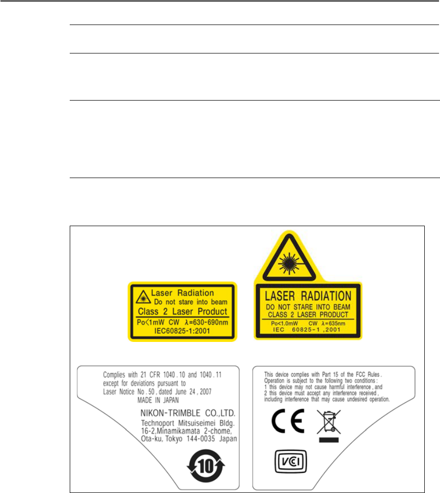
Conforming standards
Labels
Wave length 635 nm
Output power CW: Po < 1.0 mW
EU EN60825-1/Am.2 : 2001 (IEC60825-1/Am.2 : 2001)
Laser pointer: Class 2
Distance meter: Class 1
Laser plummet: Class 2 (Option)
USA FDA21CFR Part 1040 Sec.1040.10 and 1040.11
Except for deviations pursuant to Laser Notice No.50, dated June 24, 2007.
Laser pointer Laser plummet (optional)

Safety
12 Trimble TS635 Construction Total Station User Guide

CHAPTER
1
Trimble TS635 Construction Total Station User Guide 13
Introduction 1
In this chapter:
QSystem diagram
QCare and maintenance
QRelated information
This user guide describes the unique capabilities
and features available in the Trimble® TS635
construction total station.
The TS635 construction total station is a
reflectorless EDM instrument. Reflectorless
operation enables you to take measurements to
points that are inaccessible with a prism.
The software for the TS635 construction total
station makes it easy for you to learn to operate
one model of instrument and, with little
additional training, to apply that knowledge to
other models.
Before using the instrument, read this user guide
carefully. In particular, pay attention to the
warnings and cautions that appear in the Safety
section.
Your comments and suggestions about the TS635
construction total station are welcome. Please
contact us at the address given in the front of this
manual.
In addition, your feedback about the supporting
documentation helps us to improve it with each
revision. E-mail your comments to
sales@trimble.com.
1 Introduction
14 Trimble TS635 Construction Total Station User Guide
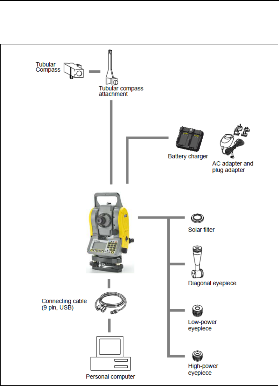
System diagram
The system diagram shows the hardware that is used with the TS635 construction
total station.
Note – You must use the TS635 total station with tribrach W30 or W30b.

Trimble TS635 Construction Total Station User Guide 15
Introduction 1
Care and maintenance
CCAUTION – The battery pack contains a Lithium-ion battery. When disposing of the
battery pack, follow the environmental guidelines as determined by law and/or local
regulations.
The TS635 construction total station is a precision instrument that you should store,
use, and clean in an appropriate way.
Storage
•Do not store the total station in hot or humid locations. In particular, you must
store the battery pack in a dry location at a temperature of less than 30 °C
(86 °F). High temperature or excessive humidity can cause mold to grow on the
lenses. It can also cause the electronic assemblies to deteriorate, and so lead to
instrument failure.
•When storing the instrument in areas subject to extremely low temperatures,
leave the carry case open.
•If you do not intend to use the tribach for an extended period, lock down the
tribach clamp knob and tighten its safety screw.
•Store the battery pack with the battery discharged.
Environmental conditions
•Do not leave the instrument in direct sunlight or in a closed vehicle for
prolonged periods. Overheating the instrument may reduce its efficiency.
•Sudden changes in temperature may cloud the lenses and drastically reduce the
measurable distance, or cause an electrical system failure. If there has been a
sudden change in temperature, leave the instrument in a closed carry case in a
warm location until the temperature of the instrument returns to room
temperature.
•If the total station has been used in wet conditions, immediately wipe off any
moisture and dry the instrument completely before returning it to the carry
case. The TS635 construction total station contains sensitive electronic
assemblies which have been well protected against dust and moisture. However,
if dust or moisture gets into it, severe damage could result.
•The carry case is designed to be watertight, but you should not leave it exposed
to rain for an extended period. If exposure to rain is unavoidable, make sure that
the carry case is placed with the Trimble nameplate facing upward.
1 Introduction
16 Trimble TS635 Construction Total Station User Guide
Cleaning
•Do not use organic solvents such as ether or print thinner to clean the
non-metallic parts of the instrument, such as the keyboard, or the painted or
printed surfaces. Doing so could result in discoloration of the surface or in
peeling of printed characters. Clean these parts only with a soft cloth or tissue
that is lightly moistened with water or a mild detergent.
•To clean the optical lenses, lightly wipe them with a soft cloth or a lens tissue
that is moistened with alcohol.
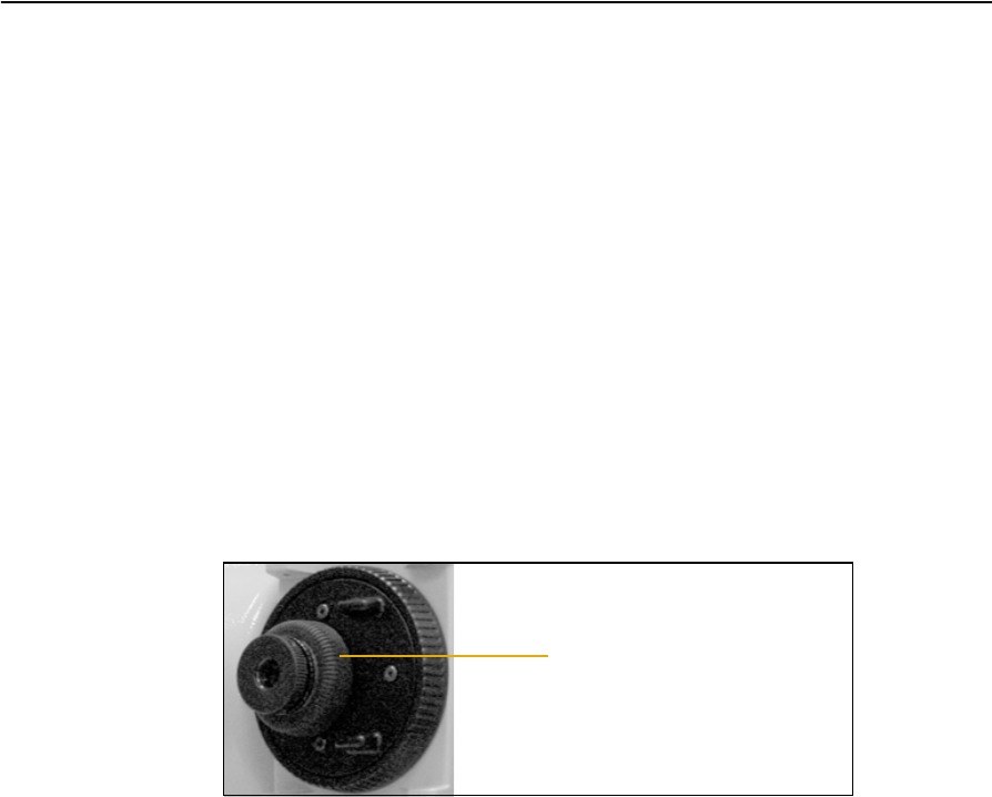
Adjusting and tightening
•When adjusting the leveling screws, stay as close as possible to the center of
each screw’s range. The center is indicated by a line on the screw.
•The reticle plate cover has been correctly mounted. Do not release it or subject
it to excessive force, for example in an attempt to make it watertight.
•Before attaching the battery pack, make sure that the contact surfaces on the
battery and TS635 construction total station are clean.
•Securely press the cap that covers the data output/external power input
connector terminal. The instrument is only watertight if the cap is attached
securely, or when the data output/external power input connector is used.
•The TS635 construction total station is not watertight when the data
output/external power input connector is used.
•Static electricity from the human body, discharged through the data
output/external power input connector, can damage the instrument. Before
handling the instrument, touch any other conductive material once in order to
remove static electricity.
•Be careful not to pinch your finger between the telescope and trunnion of the
instrument.
Reticle plate cover

Trimble TS635 Construction Total Station User Guide 17
Introduction 1
Related information
•Contact your local Trimble dealer for more information about the support
agreement contracts for software and firmware, and an extended warranty
program for hardware.
•Consider a training course to help you use your total station to its fullest
potential. For more information, go to the Trimble website at www.trimble.com.
Alternatively, send an email to trimble_support@trimble.com.

1 Introduction
18 Trimble TS635 Construction Total Station User Guide

CHAPTER
2
Trimble TS635 Construction Total Station User Guide 19
Setting up the Instrument 2
In this chapter:
QUnpacking and repacking the
instrument
QCharging the battery pack
QSetting up the tripod
QCentering the instrument
QLeveling the instrument
QFocusing the telescope
QSetting the measurement mode
and preparing the target
QViewing and changing the
measurement settings
This chapter describes how to prepare the TS635
construction total station before you use it in the
field.
2 Setting up the Instrument
20 Trimble TS635 Construction Total Station User Guide
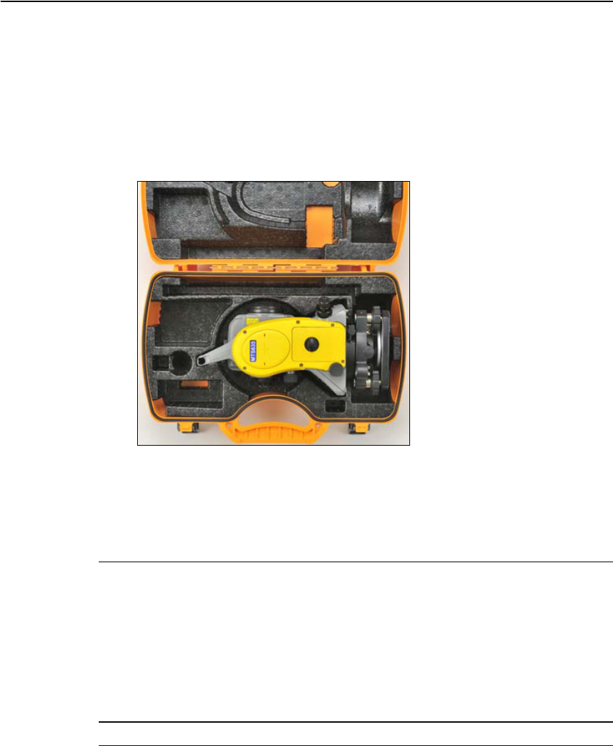
Unpacking and repacking the instrument
Note – Handle the TS635 construction total station carefully to protect it from shocks
and excessive vibration.
•To unpack the instrument, grip the carry handle and then carefully remove the
instrument from the carry case.
•To repack the instrument, refer to the following figure,
Charging the battery pack
Before charging the battery pack, read the following warnings, cautions, and notes.
CWARNING – Do not damage the rechargeable Lithium-ion battery. A damaged battery
can cause an explosion or fire, and can result in personal injury and/or property damage.
To prevent injury or damage:
– Do not use or charge the battery if it appears to be damaged. Signs of damage include,
but are not limited to, discoloration, warping, and leaking battery fluid.
– Do not expose the battery to fire, high temperature, or direct sunlight.
– Do not immerse the battery in water.
– Do not use or store the battery inside a vehicle during hot weather.
– Do not drop or puncture the battery.
– Do not open the battery or short-circuit its contacts.
CWARNING – Avoid contact with the rechargeable Lithium-ion battery if it appears to be
leaking. Battery fluid is corrosive, and contact with it can result in personal injury and/or
property damage.
To prevent injury or damage:
– If the battery leaks, avoid contact with the battery fluid.
– If battery fluid gets into your eyes, immediately rinse your eyes with clean water and

Trimble TS635 Construction Total Station User Guide 21
Setting up the Instrument 2
seek medical attention. Do not rub your eyes!
– If battery fluid gets onto your skin or clothing, immediately use clean water to wash off
the battery fluid.
CWARNING – Charge and use the rechargeable Lithium-ion battery only in strict
accordance with the instructions. Charging or using the battery in unauthorized
equipment can cause an explosion or fire, and can result in personal injury and/or
equipment damage.
To prevent injury or damage:
– Do not charge or use the battery if it appears to be damaged or leaking.
– Charge the Lithium-ion battery only in a product that is specified to charge it. Be sure to
follow all instructions that are provided with the battery charger.
– Discontinue charging a battery that gives off extreme heat or a burning odor.
– Use the battery only in equipment that is specified to use it.
– Use the battery only for its intended use and according to the instructions in the product
documentation.
CWARNING – To charge the battery pack, use only the battery charger and AC adapter
that are supplied with the instrument. Do not use any other charger or you may cause
the battery pack to catch fire or rupture. The enclosed battery pack cannot be used with
other chargers.
CWARNING – Do not cover the battery charger and AC adapter while the battery pack is
being recharged. The charger must be able to dissipate heat adequately. Coverings such
as blankets or clothing can cause the charger to overheat.
CWARNING – Avoid recharging the battery pack in humid or dusty places, in direct
sunlight, or near heat sources. Do not recharge the battery pack when it is wet. If you do,
you may receive electric shocks or burns, or the battery pack may overheat or catch fire.
CWARNING – Although the battery pack has an auto-reset circuit breaker, you should take
care not to short circuit the contacts. Short circuits can cause the battery pack to catch fire
or burn you.
CWARNING – Never burn or heat the battery. Doing so may cause the battery to leak or
rupture. A leaking or ruptured battery can cause serious injury.
CWARNING – Before storing the battery pack or battery charger, cover the contact points
with insulation tape. If you do not cover the contact points, the battery pack or charger
may short circuit, causing fire, burns, or damage to the instrument.
CWARNING – The battery is not waterproof on its own. Do not get the battery wet when it
is removed from the instrument. If water seeps into the battery, it may cause a fire or
burns.
2 Setting up the Instrument
22 Trimble TS635 Construction Total Station User Guide
Applying power
Plug in the charger to the supplied AC adapter to turn the unit on. The power input
must be 5 V with at least 4 A of current capability. Each battery may take up to 2 A
while charging.
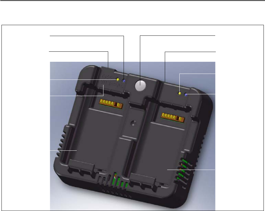
Charging the battery
Slide a battery into either battery slot to begin charging. The adjacent charge indicator
will illuminate yellow when charging is in progress. The charge indicator will change to
green when charging is complete.
Take note of the following:
•Charger slots are completely independent so a battery may be inserted
regardless of what is occurring in the other battery slot.
•Charging may take 2-4 hours if the battery was normally discharged.
•Charging may take up to 5 hours with a completely drained battery which has
been stored for several months without use.
Battery slot 2
Charge light (1)
“Calibration on”
light (1)
Battery slot 1
“Calibration on”
light (0)
Charge light (0)
Calibration button
Top edge of case
5 V, 4 A
Power jack

Trimble TS635 Construction Total Station User Guide 23
Setting up the Instrument 2
•If the charge indicator(s) are blinking, there is a problem with the battery or with
the charger.
• Lithium-ion batteries should not be charged above 40 °C to 45 °C (104 °F to
113 °F). A blinking charge light may mean that the batteries are too hot for
charging. Charging will resume after the batteries cool down.
Conditioning / calibrating a battery
You must calibrate the battery (“condition it”) once every 6 months or more often if
required. Calibration ensures that the reported remaining battery charge is accurate.
To start calibrating a battery, hold down the calibration button on the unit and then
insert a battery. Only the battery that was inserted while the button is pressed begins
calibration.
During battery calibration, the battery will be charged, discharged completely, and
then recharged again. Calibration should complete in approximately 17 hours. Do not
cover the charger vents during a calibration cycle.
•The blue calibration indicator light(s) blink slowly (on 1.5 sec, off 2 sec) while
calibration is in progress. The charge light(s) may be on or off during the
calibration cycle if the case temperature does not get too high.
•When a calibration cycle is completed, the calibration light stops blinking but
remains on until the corresponding battery is removed.
•Case temperature:
–The temperature of the bottom case may continue to climb to
approximately 43 °C before temperature regulation is enabled to keep the
case from becoming warmer. As the battery voltage drops, the case cools
down and the automatic temperature limiting is no longer necessary. This
minimizes the time required to discharge a battery.
–If the case temperature continues to become too hot internally, even after
temperature regulation is enabled, there is a secondary failsafe that aborts
the calibration completely. If an abort occurs, the calibration light(s) blink
rapidly and battery charging is re-enabled.
Detaching the battery pack
CCAUTION – To avoid problems with the electricity supply, do not touch the contacts on
the battery pack.
1. If the instrument is turned on, press [PWR] to turn it off.
2. Turn the battery box release knob counterclockwise, open the battery box cover
and then pull the battery pack out of the battery box.
2 Setting up the Instrument
24 Trimble TS635 Construction Total Station User Guide
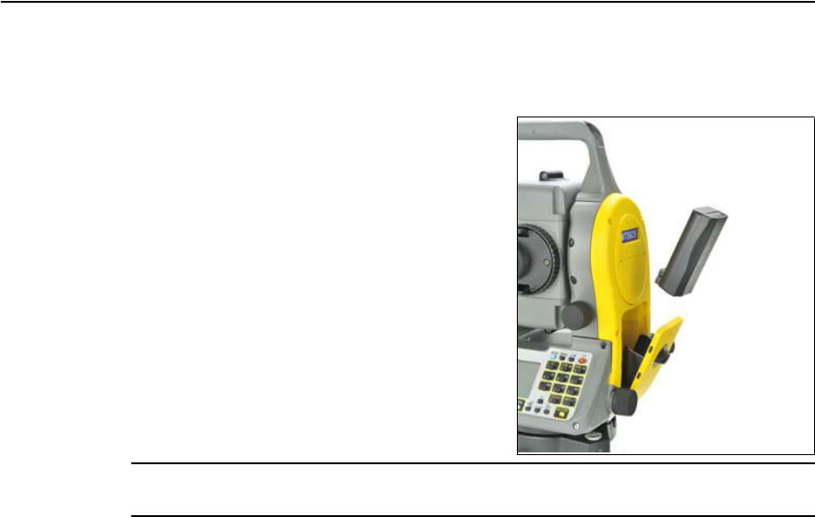
Attaching the battery pack
1. Clear any dust or other foreign particles from the battery socket.
2. Turn the battery box release knob
counterclockwise and then open the
battery box cover.
3. Put the battery pack into the battery box.
Connect the battery pack at the bottom
with the connecting direction faced
inside.
4. Close the battery box cover and then
turn the knob clockwise until you hear a
click sound.
CAUTION – If the battery pack is not attached securely, this could adversely affect the
watertightness of the instrument.

Trimble TS635 Construction Total Station User Guide 25
Setting up the Instrument 2
Setting up the tripod
CCAUTION – The tips of the tripod ferrules are very sharp. When handling or carrying the
tripod, take care to avoid injuring yourself on the ferrules.
Note – Do not carry the instrument while it is attached to a tripod.
1. Open the tripod legs far enough for the instrument to be stable.
2. Locate the tripod directly over the station point. To check the position of the
tripod, look through the center hole in the tripod head.
3. Firmly press the tripod ferrules into the ground.
4. Level the top surface of the tripod head.
5. Securely fasten the thumb screws on the tripod legs.
6. Place the instrument on the tripod head.
7. Insert the tripod mounting screw into the center hole of the base plate of the
instrument.
8. Tighten the tripod mounting screw.
2 Setting up the Instrument
26 Trimble TS635 Construction Total Station User Guide
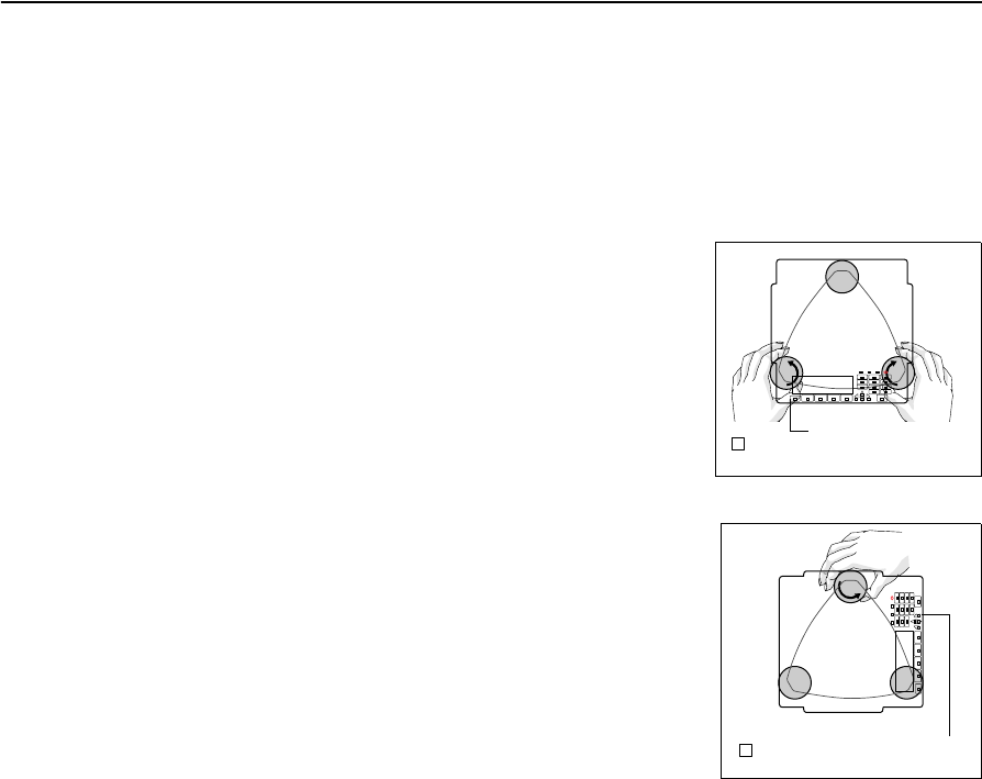
Centering the instrument
When you center the instrument, you align its central axis precisely over the station
point. To center the instrument, you can use the optical plummet, the laser plummet,
or a plumb bob. The plumb bob is sold separately.
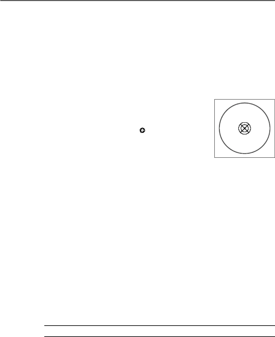
Centering with the optical plummet
Note – For high accuracy, check and adjust the optical plummet before you center the
instrument.
1. Set up the instrument on the tripod. See above.
2. Look through the optical plummet and align the reticle
with the station point. To do this, turn the leveling
screws until the center mark of the reticle is directly
over the image of the station point.
3. While supporting the tripod head with one hand, loosen
the tripod leg clamps and adjust the lengths of the legs
until the air bubble is in the center of the circular level.
4. Tighten the tripod leg clamps.
5. Use the electronic level to level the instrument. See also Leveling the
instrument, page 28.
6. Look through the optical plummet to make sure that the image of the station
point is still in the center of the reticle mark.
7. If the station point is off-center, do one of the following:
–If the station point is slightly off-center, loosen the tripod mounting screw
and then center the instrument on the tripod. Use only direct movement to
center the instrument. Do not rotate it.
When the instrument is centered, tighten the mounting screw.
–If there is major displacement of the station point, repeat this procedure
starting with Step 2.
Centering with the laser plummet
CCAUTION – Do not see the laser directly.
Note – For high accuracy, check and adjust the laser plummet before you center the
instrument.
1. Set up the instrument on the tripod. See page 25.
2. Turn on the laser plummet.

Trimble TS635 Construction Total Station User Guide 27
Setting up the Instrument 2
3. Align the laser pointer to the station point. To do this, turn the leveling screws
until the laser pointer is over the station point.
4. While supporting the tripod head with one hand, loosen the tripod leg clamps
and adjust the lengths or the legs until the air bubble is the center of the circular
level.
5. Tighten the tripod leg clamps.
6. Use the electronic level to level the instrument. See Leveling the instrument,
page 28.
7. Check that the laser pointer is over the station point.
8. If the station point is off-center, do one of the following:
–If the station point is slightly off-center, loosen the tripod mounting screw
and then center the instrument on the tripod. Use only direct movement to
center the instrument. Do not rotate it.
When the instrument is centered, tighten the mounting screw.
–If there is major displacement of the station point, repeat this procedure
starting with Step 2.
Centering with a plumb bob
1. Set up the instrument on the tripod. See page 25.
2. Hang the plumb line on the hook of the tripod mounting screw.
3. Adjust the length of the plumb line so that the tip of the plumb bob is at the
height of the station point.
4. Loosen the tripod mounting screw slightly.
5. Using both hands to support the outer side of the tribrach, carefully slide the
instrument about on the tripod head until the tip of the plumb bob is positioned
over the exact center of the station point.
Note – To confirm that the instrument is precisely aligned, check its position from two
directions at right-angles to each other.
2 Setting up the Instrument
28 Trimble TS635 Construction Total Station User Guide
Leveling the instrument
When you level the instrument, use th electronic level to you make the vertical axis of
the instrument exactly vertical. During leveling, always set the instrument in the Face 1
direction. See Figure3.1, page 34.
To level the instrument:
1. Move the bubble into the circle on the circular
level and then turn on the power.
2. Rotate the alidade until the bottom edge of the
keyboard panel is parallel to the two of the leveling
screws (B and C).
3. Use leveling screws B and C to move the bubble
into the center of the electronic level.
4. Rotate the alidade approximately 90°.
5. Use leveling screw A to move the bubble into the
center of the electronic level.
6. Repeat Step 1 through Step 5 to center the bubble
in both positions.
7. Rotate the alidade 180°.
If the bubble in the electronic level remains centered, the
instrument is level. If the bubble moves off center, adjust
the electronic level. For detailed instructions, see
Adjusting the electronic level, page 118.
B C
A
1
Bottom edge of the
keyboard panel
A
BC
CB
A
2
Bottom edge of
the keyboard panel
Trimble TS635 Construction Total Station User Guide 29
Setting up the Instrument 2
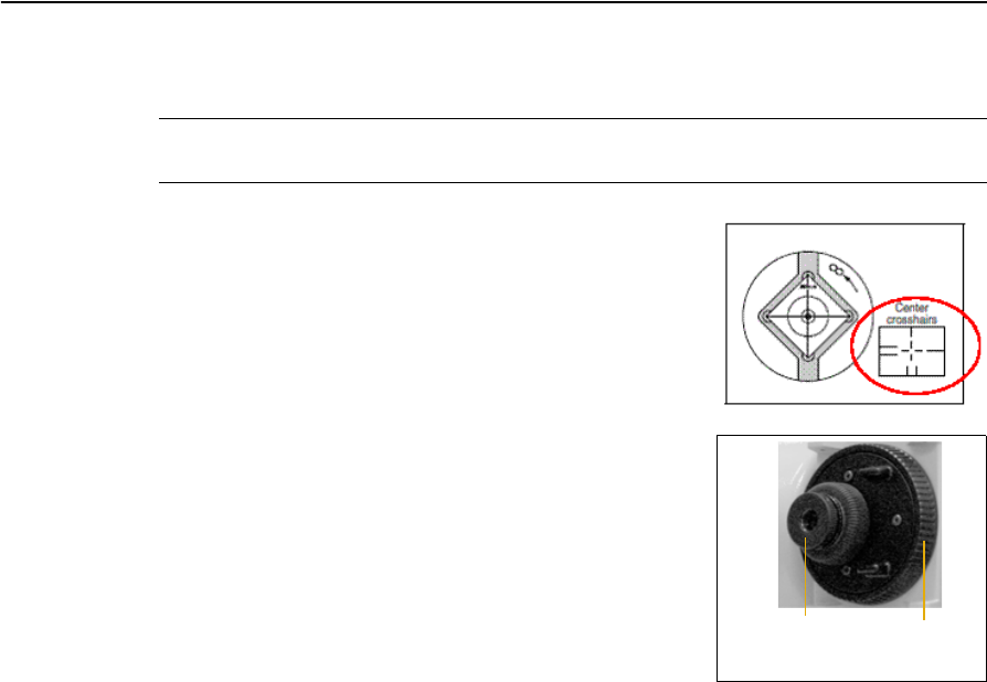
Focusing the telescope
CWARNING – Never look at the sun through the telescope. If you do, you may damage or
lose your eyesight.
When you sight the instrument, you aim the telescope at
the target, bring the target image into focus, and align the
image with the center cross-hairs of the reticle.
To sight the instrument:
1. Adjust the diopter:
a. Aim the telescope at a blank area, such as the
sky or a piece of paper.
b. Looking through the eyepiece, rotate the
diopter ring until the reticle cross-hairs are in
sharp focus.
2. Eliminate parallax:
a. Aim the telescope at the target image.
b. Rotate the focusing ring until the target image is in sharp focus on the
reticle cross-hairs.
c. Move your eye vertically and laterally to check whether the target image
moves relative to the reticle cross-hairs.
–If the target image does not move, there is no parallax.
–If the target image does move, rotate the telescope focusing ring and repeat
Step 2c.
3. Rotate the tangent screw. The final turn of the tangent screw should be in a
clockwise direction, to align the target accurately on the center cross-hairs.
Diopter ring Telescope
focusing ring
2 Setting up the Instrument
30 Trimble TS635 Construction Total Station User Guide
Setting the measurement mode and preparing the target
The TS635 construction total station has two measurements modes: Prism mode
(Prism) and Reflectorless mode (N-Prism). To change the mode at any time from
any observation screen, hold down [MSR1] or [MSR2].
Set the measurement mode depending on the target you want to measure, as shown
here.
In some cases, you can measure to another target that is not appropriate to the set
measurement mode.
Note – The TS635 Total Station is Laser Class 1 in the measurement function, and Laser
Class 2 in the Laser Pointer function. Do not sight the prism when the Laser Pointer is on.
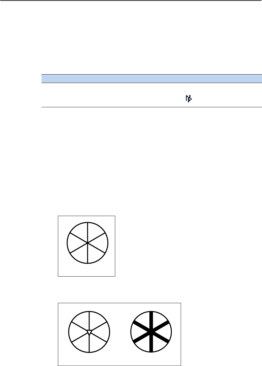
Measurement with a prism
As the TS635 construction total station is extremely sensitive, multiple reflections on
the prism surface can sometimes cause a significant loss in accuracy.
To maintain the accuracy of your measurements:
•Use a prism with thin edges.
Do not use a prism with scratches, a dirty surface, a chipped center, or thick
edges.
Target Target settings Indicator on status bar
Prism, reflector sheet Prism mode No sign
Other, reflective materials Reflectorless mode
Thin edges
Chipped center Thick edges
Trimble TS635 Construction Total Station User Guide 31
Setting up the Instrument 2
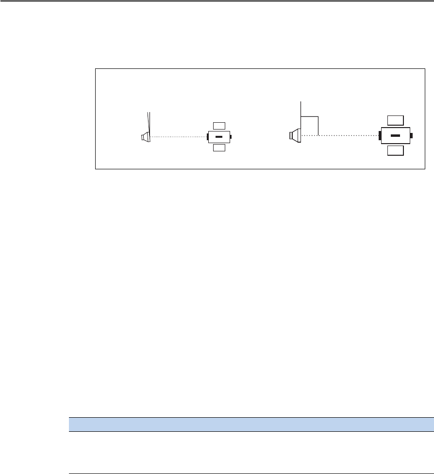
•When measuring a short distance, incline the prism slightly so that the EDM
can ignore unnecessary reflections on the prism surface, as shown below.
•Hold the prism securely in place and do not move while taking measurements.
In Prism mode, to avoid false measurements on objects other than the prism or
reflector-sheet, targets that are less reflective than the prism or reflector sheet are not
measured. Even if you start a measurement, measured values are not displayed. To
measure less reflective objects, use the N-Prism (Reflectorless) mode.
Measurement in reflectorless (N-Prism) mode
The TS635 Construction Total Station enables reflectorless measurements up to 300 m
(984 feet).
The intensity of the reflection from the target determines the distance the TS635 can
measure in this mode. The color and condition of the target surface also affect the
measurable distance, even if the targeted objects are the same. Some less-reflective
targets may not be measured.
The following table describes some examples of targets and approximate measuring
distances:
Measurable distances may be shorter or measurement intervals may be longer if either
of the following conditions apply:
•the angle of the laser against the target is small
•the surface of the target is wet
In direct sunlight, the measurable distance may be shorter. In this case, try to throw a
shadow on the target.
Targets with completely flat surfaces, such as mirrors, cannot be measured unless the
beam and the target are perpendicular to each other.
Target You can measure approximately ...
Traffic signs, reflectors 500 meters (1640 feet)
Paper (white), veneer (new) 300 meters (990 feet)
Wall (brightly painted), brick 100 to 200 meters (330 to 660 feet)
Not completely square to
the sighting axis
Completely square to
the sighting axis
2 Setting up the Instrument
32 Trimble TS635 Construction Total Station User Guide
Make sure there are no obstacles between the instrument and the target when taking
measurements. When you need to take measurements across a road or a place where
vehicles or other objects are frequently moving, take several measurements to a target
for the best result.
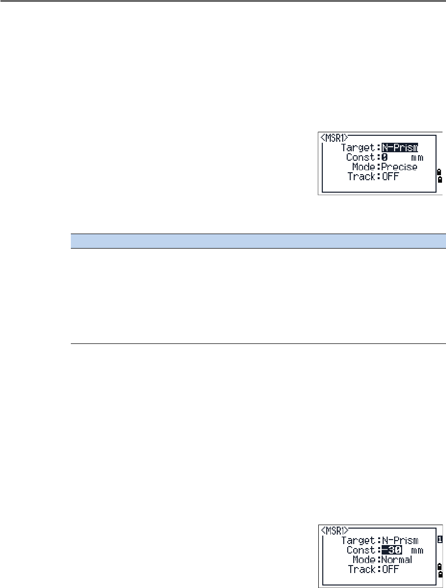
Viewing and changing the measurement settings
Hold down [MSR1] or [MSR2] for one second.
•To move the cursor between the fields, press [^]
or [v].
•To change the value in the selected field, press [<]
or [>].
The available values are:
Target field
If the measurement is started with the Target field set to Prism mode, there is a dash in
front of the prism constant, for example –18 mm.
If the measurement is started with the Target field set to N-Prism (Reflectorless) mode,
there is square bracket in front of the prism constant, for example ]18 mm.
The displayed symbol will continuously move from left to right over the prism
constant in the display.
Prism constant
The factory default of the prism constant value of the
TS635 construction total station is -30 mm.
Change the prism constant to match the constant
value of the prism you are using.
Once you have set up the instrument, you can turn on the TS635 construction total
station, change the instrument settings, and start a job. See also Getting Started,
page 33.
Field Values
Target Prism mode
N-Prism mode
Constant (prism constant) -999 mm through 999 mm
Mode Precise
Normal
Track Track (continuous MSR) ON
Track (continuous MSR) OFF

CHAPTER
3
Trimble TS635 Construction Total Station User Guide 33
Getting Started 3
In this chapter:
QParts of the instrument
QInstrument keyboard and display
QTurning on the instrument
QTurning off the instrument
QRegional configuration
QList available jobs or data
QEntering data
QCreating or opening a job
QMeasuring distances
After you set up the instrument, see page 19, you
can start using the TS635 Construction Total
Station.
This chapter describes the basic features of the
instrument, how to turn it on, change the
instrument settings, and start a job.
3 Getting Started
34 Trimble TS635 Construction Total Station User Guide
Parts of the instrument
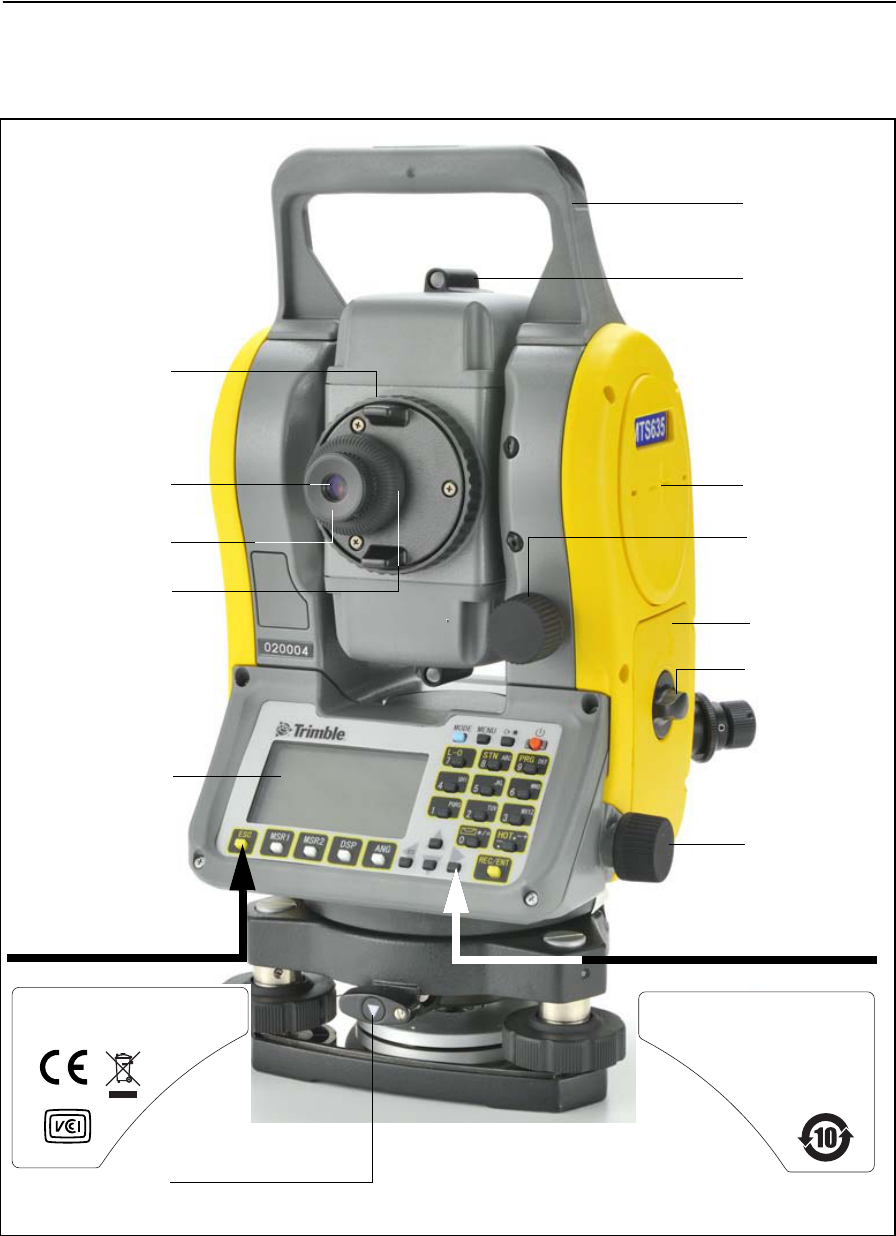
Figure 3.1 and Figure 3.2 show the main parts of the TS635 Construction Total Station.
Figure 3.1 Back view of the TS635 Construction Total Station
Telescope
Telescope
Diopter ring
Carrying
Vertical tangent
Horizontal
screw
tangent screw
focusing ring
handle
eyepiece
Face 1 display and
keyboard
The laser safety label shown
below is attached to the
Optical sight
(finder)
Horizontal axis
indication mark
Battery box
Battery box
release knob
Reticle plate cover
Complies with 21 CFR 1040 . 10 and 1040 . 11
except for deviations pursuant to
Laser Notice No . 50 , dated June 24 , 2007
MADE IN JAPAN
Technoport Mitsuiseimei Bldg.
16
-
2,Minamikamata 2
-
chome,
Ota
-
ku, Tokyo 144
-
0035 Japan
NIKON
-
TRIMBLE CO.,LTD.
underside of the keyboard.
Tribrach clamp
knob
The label shown below is
attached to the underside
of the keyboard.
This device complies with Part 15 of the FCC Rules .
Operation is subject to the following two conditions :
1 this device may not cause harmful interference , and
2 this device must accept any interference received ,
including interference that may cause undesired operation.
Trimble TS635 Construction Total Station User Guide 35
Getting Started 3
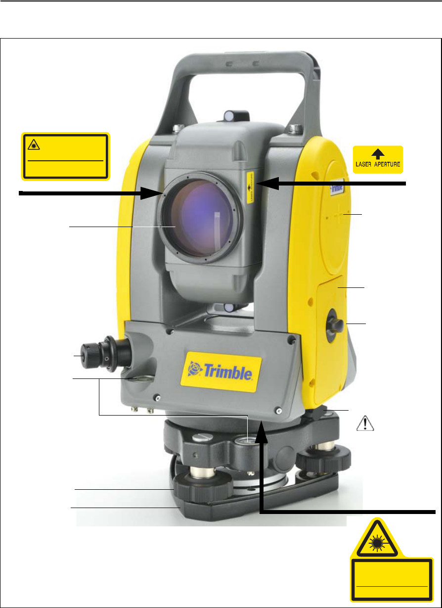
Figure 3.2 Front view of the TS635 Construction Total Station
Objective
The laser safety label shown below
is attached to the side
LASER LIGHT IS
THIS PART
EMITTED FROM
Data output/
input connector
(input voltage
4.5-5.2 V DC)
Po
Ƀ
1mW CW
Ё
=630
-
690nm
Class 2 Laser Product
Do not stare into beam
Laser Radiation
IEC60825-1:2001
Optical plummet
of the telescope.
The laser safety label
shown below is
attached to the
telescope.
Horizontal axis
indication mark
Battery box
Battery box
external power
The laser safety label
shown below is
attached here
Circular level
(underneath).
Po
<
1.0mW CW Ё=635nm
IEC 60825
-
1 ,2001
LASER RADIATION
DO NOT STARE INTO BEAM
CLASS 2 LASER PRODUCT
Leveling screw
Tribrach
(shown here) or
optional optical
plummet
release knob
3 Getting Started
36 Trimble TS635 Construction Total Station User Guide
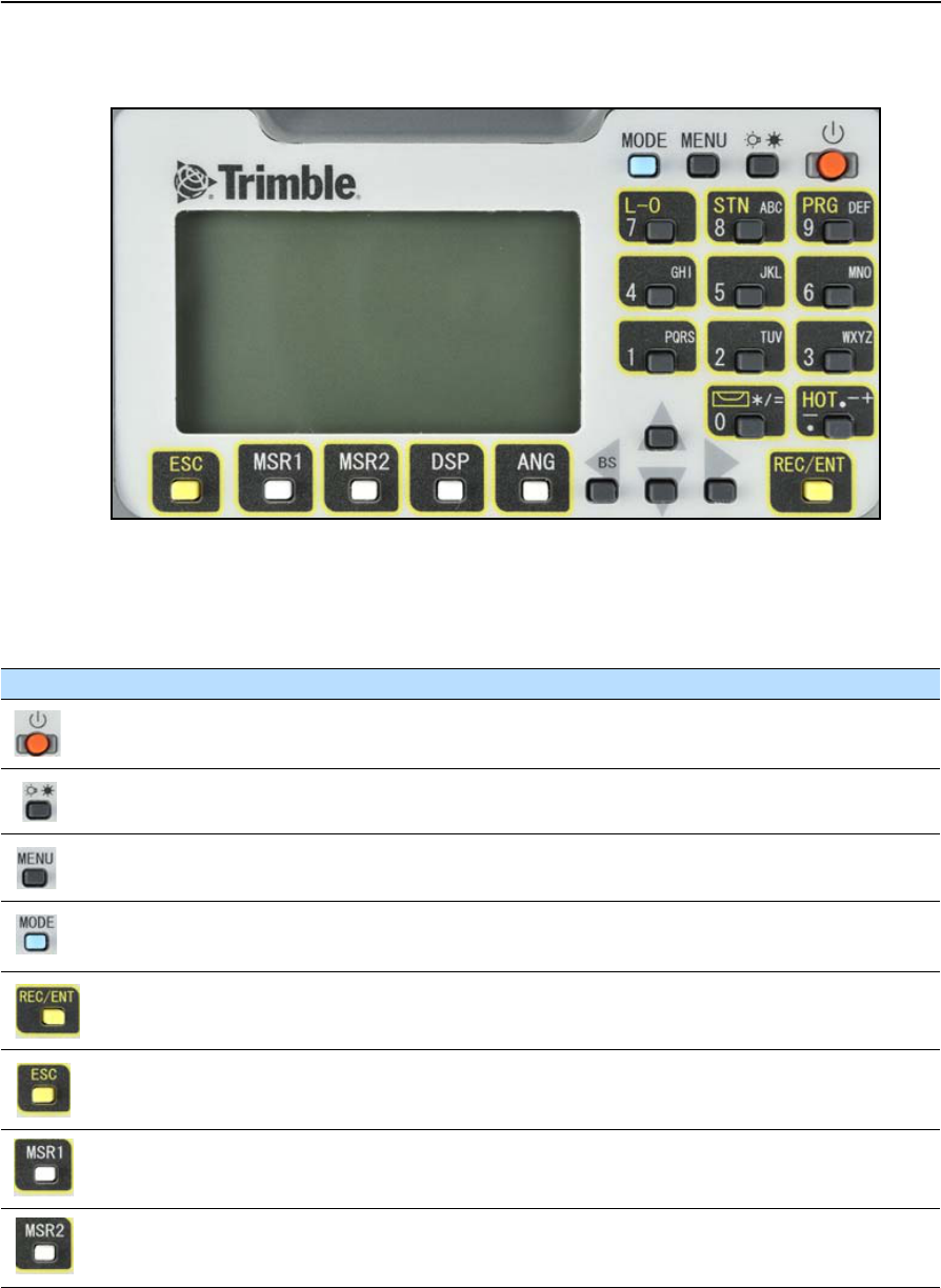
Instrument keyboard and display
Instrument keyboard
Use the buttons on the instrument keyboard to carry out the following functions:
Button Function See ...
Turns the instrument on or off. page 44
Illumination button. Turns the backlight on or off.
Provides access to the switch window if held down for one second.
page 39
Displays the MENU screen. page 91
Changes the button input mode between alphanumeric and numeric if
pressed when you are in a PT or CD field.
page 41
Records measured data, moves on to the next screen, or confirms and accepts
the entered data in input mode.
page 89
Returns to the previous screen.
In numeric or alphanumeric mode, deletes input.
Starts distance measurement, using the measure mode settings for the [MSR1]
button.
Displays measurement mode settings, if held down for one second.
page 53
Starts distance measurement, using the measure mode settings for the [MSR2]
button.
Displays measurement mode settings, if held down for one second.
page 53
Trimble TS635 Construction Total Station User Guide 37
Getting Started 3
Status bar
The status bar appears on the right of every screen. It contains icons that indicate the
status of various system functions.
Laser pointer indicator
The icon appears as you turn on the laser pointer. When the icon appears on the
screen, the emitting power is laser class 2:
If there is no icon, the laser pointer is off.
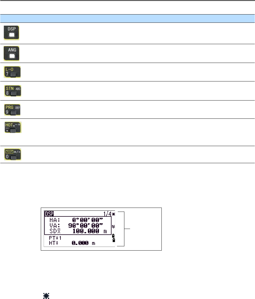
Moves to the next available display screen.
Changes the fields that appear on the DSP1, DSP2, and DSP3 screens, if held
down for one second.
page 40
Displays the Angle menu. page 60
Displays the Layout function menu.
In numeric mode, enters 7.
page 60
Displays the Station Setup menu.
In numeric mode, enters 8. In alphanumeric mode, enters A, B, C, or 8.
page 60
Displays the Programs menu.
In numeric mode, enters 9. In alphanumeric mode, enters D, E, F, or 9.
page 75
Displays the (HOT) menu, which includes Height of Target and Temp-Press
settings.
In numeric mode, enters – (minus). In alphanumeric mode, enters. (period), –
(minus), or + (plus).
page 42
Displays the Bubble indicator.
In numeric mode, enters 0. In alphanumeric mode, enters *, /, =, or 0.
page 42
Laser pointer ON.
Button Function See ...
Status bar
3 Getting Started
38 Trimble TS635 Construction Total Station User Guide
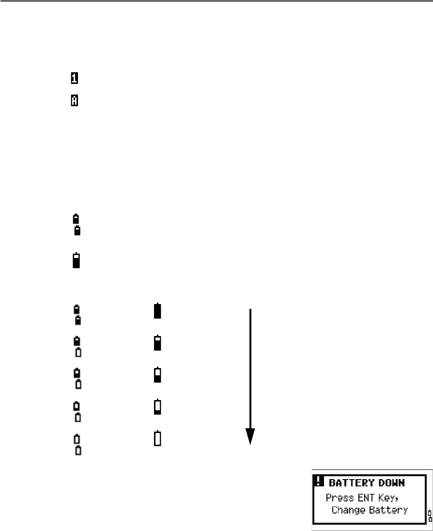
Input mode indicator
The input mode indicator appears only when you are entering points or coordinates. It
shows the data input mode:
Battery indicator
Shows each voltage level of the right and left internal batteries individually. When the
external battery is connected with the instrument, its voltage is shown.
If the battery level is critically low, a message appears.
Input mode is numeric. Press a button on the number pad to enter the number
printed on the button.
Input mode is alphabetic. Press a button on the number pad to enter the first letter
printed beside the button. Press the button repeatedly to cycle through all the
letters assigned to that button.
For example, to enter the letter O in alphabetic mode, press [5] three times.
Internal batteries:
• Top: left battery
• Bottom: right battery
External battery
Internal batteries External battery
Battery level indication
Battery low
Trimble TS635 Construction Total Station User Guide 39
Getting Started 3
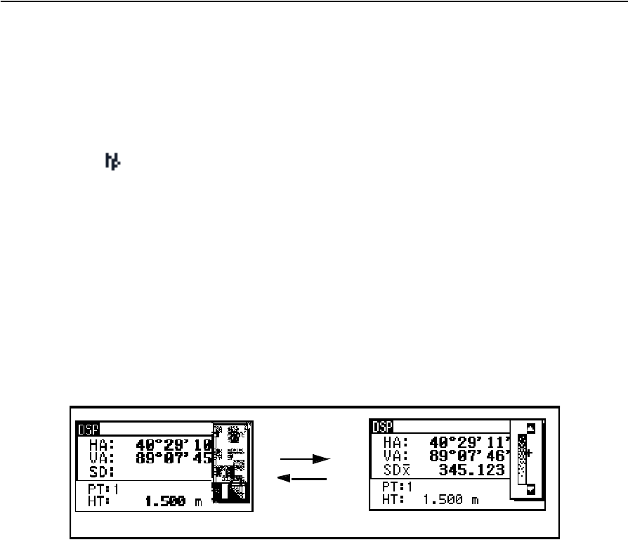
EDM measurement status
When you are taking measurements, the EDM measurement status shows the mode
that is being used.
When you display observation data, the EDM measurement status shows the mode
that was used when the data was collected.:
If there is no icon, Prism mode is being used.
LCD backlight, laser pointer, beep sound, and contrast adjustment
Press the illumination key to open the the 4-switch window and then press:
[1] to turn the LCD backlight on/off
[2] to turn the laser pointer on /off
[3] to turn the beep sound on /off
[4] to open the contrast adjustment window.
Do the following:
•To turn on/off each function, press [ENT] when the option 1, 2, 3 or 4 is selected or
directly press the [1], [2], [3], or [4] key. Holding down the illumination key for one
second also turns on/off the LCD backlight.
•To move the cursor up and down, press [^] or [v].
•To adjust the constrast, in the contrast adjustment window, press [>] or [<] .
To close the window, press [ESC].
Reflectorless mode
[ENT] / [4]
[ESC]
Switch setup window Contrast adjustment window
3 Getting Started
40 Trimble TS635 Construction Total Station User Guide
Switch 1: Turning on/off the LCD backlight
Switch 2: Turning on/off the laser pointer
Switch 3: Turning on/off the sound
[DSP] button
Use the [DSP] button to change the current display screen or to change display settings.
Switching between display screens
When several display screens are available:
•the DSP indicator appears at the top left of the
screen
•the screen indicator ( for example, 1/4) appears
at the top right
To move to the next available screen, press [DSP].
For example, if you are currently in the second display
screen, press [DSP] to move to the third display screen.
The screen indicator changes from 2/4 to 3/4.
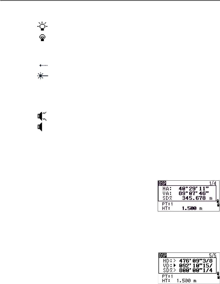
When the secondary distance unit is set, an additional
screen is available. It shows the HD, VD, and SD values.
See also Other settings, page 94.
The smallest unit of display for distances measured in
feet-and-inches is 1/16 in. Smaller units are impractical
in the field.
When the actual value is greater than 99999'11"15/16, the > symbol appears. If the
actual distance is less than –9999'11''15/16, the ` (solid triangle) symbol appears. This
does not affect calculations. The precise value is used internally in all cases.
LCD backlight is on
LCD backlight is off
Laser pointer is on
Laser pointer is off
The icon appears while turning on the laser pointer. When the icon is on the screen, the
emitting power is Laser Class 2.
Sound is on
Sound is off
Trimble TS635 Construction Total Station User Guide 41
Getting Started 3
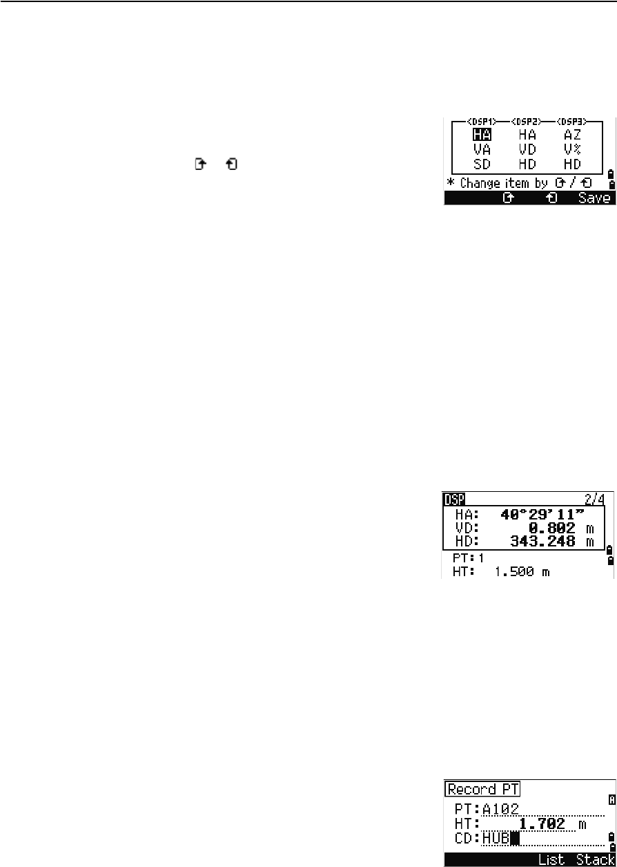
Customizing items in the Basic Measurement Screen (BMS)
To customize the items that are displayed on the DSP1, DSP2, and DSP3 screens:
1. Hold down [DSP] for one second.
2. Use the arrow buttons [^], [v], [<], and [>] to highlight
the item that you want to change:
3. Press the or softkey to scroll through the list
of items that can be displayed for this item.
The items that you can choose from are HA, AZ,
HL, VA, V%, SD, VD, HD, Z, and (none).
4. To save your changes, press the Save softkey.
Alternatively, highlight the last item for DSP3 and press [ENT]. The DSP screens
show the items you have selected.
Except for the (none) item, you cannot display the same item on more than one
line of the same screen.
The items displayed in the DSP1, DSP2, DSP3, and DSP4 screens are also used in
the corresponding Layout screens (LO2, LO3, LO4, and LO5).
You can also customize the displayed items in Layout.
Header characters
The following header characters appear in DSP screens:
•Colon (:) indicates that tilt correction is applied
to the value.
•Hash symbol (#) indicates that tilt correction is
off.
•Underscore (_) under the tilt correction
character indicates that Sea Level Correction or
Scale factor is applied.
[MODE] button
The [MODE] button is on the top row of the TS635 keypad. Use it to change the keyboard
mode for the current screen.
Changing the input mode while entering points or codes
When the cursor is in a point (PT) or code (CD) field,
press [MODE] to change the input mode between
alphanumeric (A) and numeric (1).
The input mode indicator in the status bar changes to
show the current input mode.
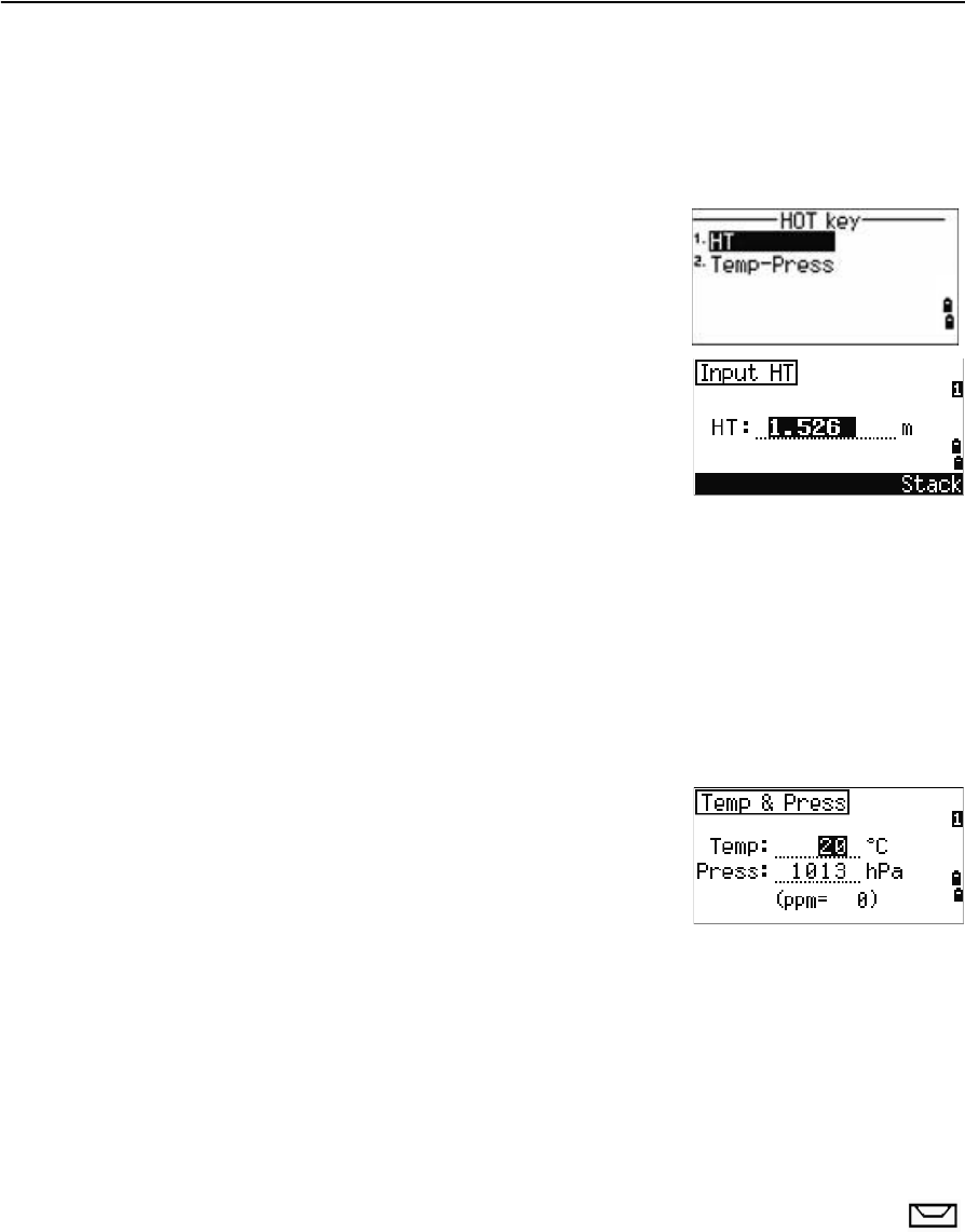
3 Getting Started
42 Trimble TS635 Construction Total Station User Guide
When the cursor is in a height (HT) field, only numeric input mode is available.
Pressing [MODE] has no effect when the cursor is in a HT field.
[HOT] key
The HOT key menu is available from any observation
screen. To display the HOT key menu, press [HOT].
Changing the height of the target
1. Press [HOT] to display the HOT menu.
2. Do one of the following:
–Press [1].
–Select HT.
3. Press [ENT].
4. Enter the target height or select the height from the HT stack.
Note – To display the HT stack, press the Stack softkey. The HT stack stores the last 20
HT values entered.
Setting the current temperature and pressure
1. Press [HOT] to display the HOT menu.
2. Do one of the following:
–Press [2].
–Select Temp-Press.
3. Press [ENT].
4. Enter the ambient temperature and pressure.
The ppm value is updated automatically.
Bubble indicator
The bubble indicator appears if the instrument goes out of level while the
compensator is turned on. It also appears directly after the start up screen.
To display the bubble indicator in an observation screen at any other time, press .
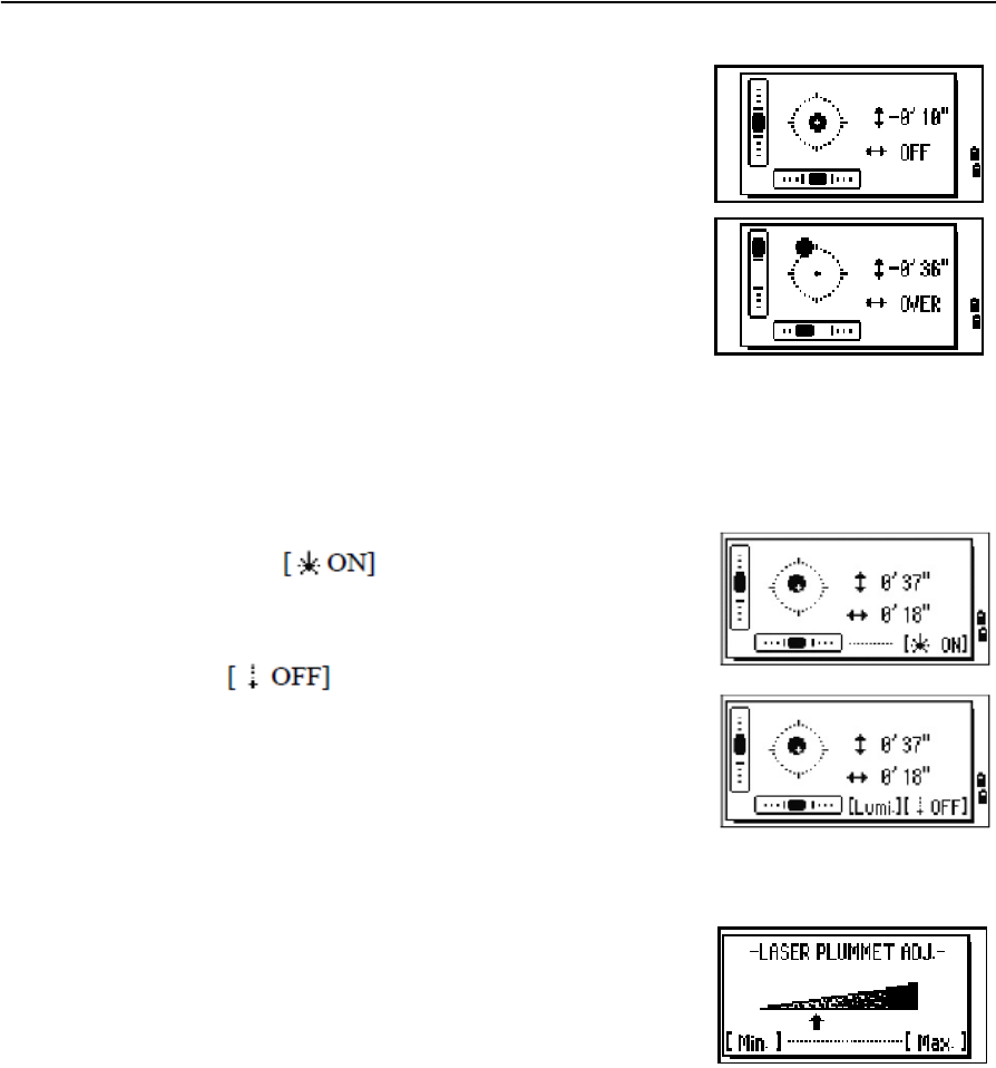
Trimble TS635 Construction Total Station User Guide 43
Getting Started 3
The TS635 Construction Total Station has a two-axis
level compensation. To turn the leveling compensators
on or off, press [<] or [>]. When the levelling
compensators are turned off, the text OFF appears on
the screen.
If the instrument is more than ±3'30" out of level, the
text OVER appears on the screen.
To return to the observation screen, press [ESC] or [ENT].
Laser plummet
Laser plummet on / off
Do one of the following:
•To turn the laser plummet switch on,
press .
•To close the bubble indicator window, press [ESC].
•To turn the laser plummet switch off, press
.
•To open the luminance adjustment window,
press [Lumi.].
•To turn the laser plummet switch off and close
the bubble indicator window, press [ESC].
Laser luminance adjustment
Laser luminance can be set to 4 levels.
•To set the luminance brighter by one level, press
[Light] once.
•To set the luminance darker by one level, press
[Dark] once
To return to the bubble indicator window, press [ESC] or
[ENT].
The current setting of leveling compensators is indicated by header characters (:, #, :, and
#) after field labels (such as HA, VA, SD, and HD) in observation screens. For more
information, see Header characters, page 41.
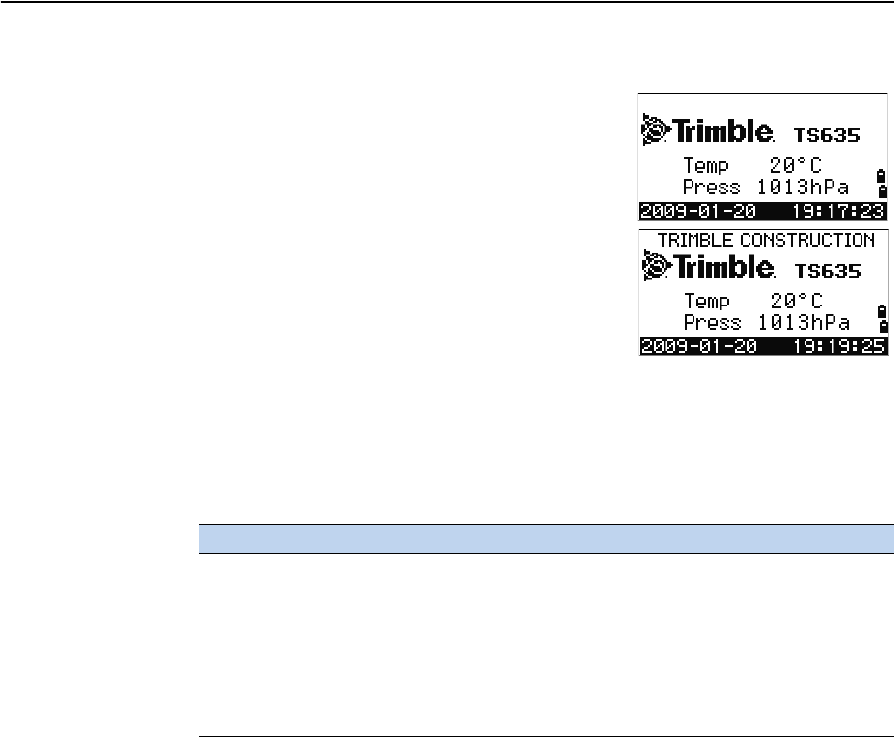
3 Getting Started
44 Trimble TS635 Construction Total Station User Guide
Turning on the instrument
Press the [PWR] button. The start-up screen appears. It
shows the model name, current temperature, pressure,
date, and time. The display automatically changes to
the electronic level after two seconds.
If you entered your name or your company’s name in
the Owner’s detail field, the text from this field appears
on the start-up screen. To set the Owner’s detail field,
press [MENU] and then select Settings / Other.
See also Other settings, page 94.
Turning off the instrument
1. Press [PWR] and [ENT].
2. Do one of the following:
Sleep mode
To put the instrument into sleep mode, do one of the following:
•In the Press [ENT] → OFF screen, press the Sleep softkey.
•Enable the Power Save setting. See also Power saving, page 94.
The instrument wakes up if any of the following events occur:
•You press a button
•The instrument receives a remote control command
•You rotate the alidade
•You tilt the telescope
Press... To...
[ENT] again turn off the instrument
the Reset softkey reboot the software and re-start the instrument
access the Basic Measurement Screen (BMS) without an open
job.
the Sleep softkey put the instrument into power-saving mode
[ESC] cancel the power-off process and return to the previous
screen
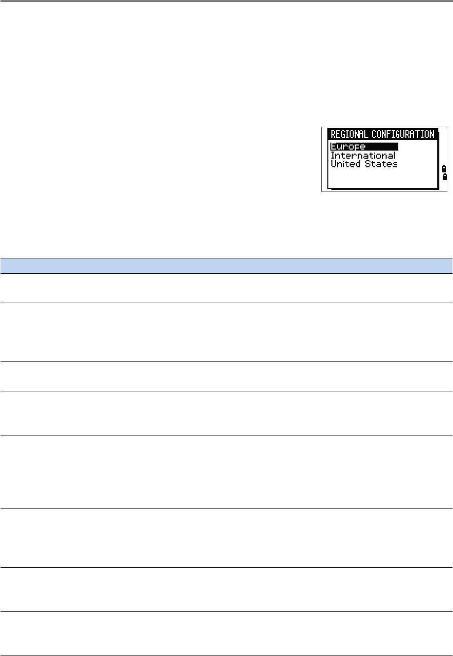
Trimble TS635 Construction Total Station User Guide 45
Getting Started 3
Regional configuration
To provide easier configuration for common regional settings, you can quickly
configure the TS635 Construction Total Station to a pre-set combination of default
regional settings. The Regional Configuration screen appears only after the language
configuration is complete and the instrument has rebooted.
1. Follow the steps in the language section on page 95.
Once the instrument reboots, the Regional
Configuration screen appears.
2. Press [^] or [v] to highlight the required regional
settings and then press [ENT].
3. If you do not want to change the current settings,
press [ESC] and quit. The instrument will continue
to use the last settings that were configured.
The settings affected by the Regional Configuration screen are:
Category Setting Europe International United States
Angle VA zero Zenith Zenith Zenith
Resolution 5" 5" 5"
Distance Scale 1.000000 1.000000 1.000000
T-P Corr. On On On
Sea Level Off Off Off
C&R corr. 0.132 0.132 0.132
Coordinates Order ENZ ENZ NEZ
Label ENZ ENZ NEZ
Power Save Main Unit Off Off Off
EDM Unit Off Off Off
Sleep 5 minutes 5 minutes 5 minutes
Communication Ext. Comm Nikon Nikon Nikon
Baud 4800 4800 4800
Length 8 8 8
Parity None None None
Stop bit 1 1 1
Units Angle GON DEG DEG
Distance meters meters US-ft
Temp °C °C °F
Press mm Hg mm Hg In Hg
Rec Rec Data ON ON ON
CD Field ON ON ON
Add Const 1000 1000 1000
Others XYZ disp Fast Fast Fast
2nd Unit None None None
CD Input <ABC> <ABC> <ABC>
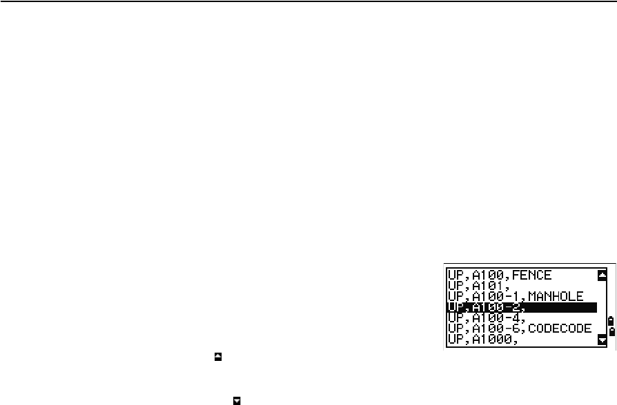
3 Getting Started
46 Trimble TS635 Construction Total Station User Guide
The default regional configuration pre-set is “Europe” settings. See also Settings (basic
job settings), page 90.
List available jobs or data
The TS635 Construction Total Station lists available jobs or data when you do any of
the following:
•view or edit data (Press [MENU] then select Data)
•open the Job Manager (Press [MENU] then select Job)
•search for points or codes
The current cursor position is shown in inverted colors
(it appears as white text on a black background).
Press [^] to move the cursor one line up, or press [v] to
move the cursor one line down.
If the Page Up icon appears, there are more pages
before the current page. Press [<] to move up one page.
If the Page Down icon appears, there are more pages
after the current page. Press [>] to move down one page.
To select an item from the list, move the cursor onto the
item and press [ENT].
Entering data
You can enter the following into the TS635 Construction Total Station:
•A point name or number, see page 46
•A code, see page 49
Entering a point name or number
You can use numeric or alphanumeric names up to 20 characters long to identify
points.
The default name for a new point is the last point name entered, with the last digit
incremented. For example, if the last point name was A100, the default name for the
next point is A101.
If the last character of the previous point name is alphabetic, the default point name is
identical to the last point name.
When the cursor is in a PT (point) field, there are several ways to specify a point, or to
enter coordinates. You can:
•Enter an existing point, see page 47
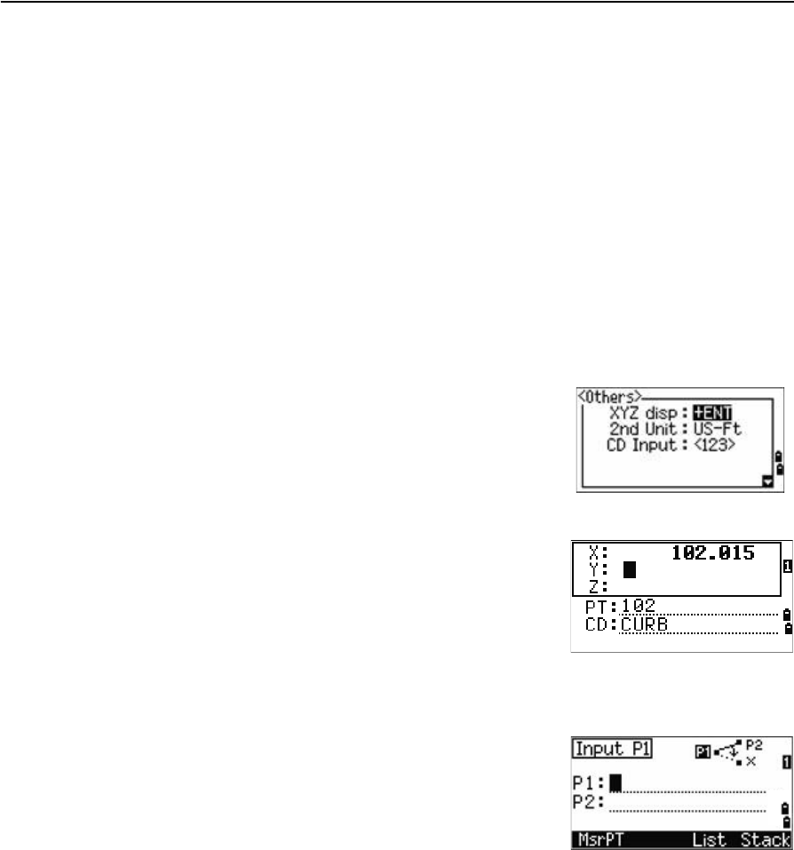
Trimble TS635 Construction Total Station User Guide 47
Getting Started 3
•Enter a new point, see page 47
•Press [ENT] without a point name, see page 47
•Specify a wildcard, see page 48
•Record an instant measurement, see page 48
•Enter a point from a point stack, see page 49
•Enter a point from the point list, see page 49
Entering an existing point
When you enter a known point name or number, the coordinates of that point are
briefly displayed. A short beep sounds before the next screen appears or the next field
is selected.
To adjust the duration of the coordinate window
display, press [MENU] then select Settings /
Others. To leave the window open until you press
[ENT], set the XYZ disp field to +ENT. See also page 94.
Entering a new point
When you enter a new point name or number, a
coordinate input screen appears. Enter the coordinates
for the point in NE, NEZ, or elevation-only (Z) format.
To store the point in the current job, press [ENT] on the
last line (the CD field).
Pressing [ENT] without a point name
To use a point without recording the coordinates, press
[ENT] in a PT field, without entering a point name.
The input coordinates are used in the calculation but
they are not saved in the database. The message This
PT will not be recorded appears.
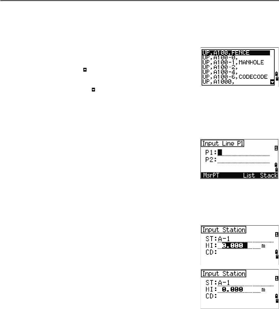
3 Getting Started
48 Trimble TS635 Construction Total Station User Guide
Specifying a wildcard (*)
If you include an asterisk (for example, A100*) when you enter a point or code name, a
list of points that match the entered text appears.
Use [^] or [v] to move the cursor to the point that you
want to use. Then press [ENT].
If the Page Up icon appears, you can use it to move up
one page on the list. You can also use [<].
If the Page Down icon appears, you can use it to move
down one page. You can also use [>].
When you select a point from the list, its coordinates are displayed and a beep sounds.
Entering a point by recording an instant measurement
1. Press the MSR softkey:
An observation screen appears.
2. To start a measurement, press [MSR1] or [MSR2].
3. To change the height of the target, select the HT
softkey.
4. When you have finished the measurement, press
[ENT] to go to the point recording screen.
5. Enter the point or code name and then press [ENT].
When you move the cursor to a field, the current or
default value appears in inverted colors. (It appears as
white text on a black background). This is the default
Replace All input mode.
To change the input mode to Overwrite and highlight
the first character, press [>]. To move the cursor to the
end of the string, press [<].
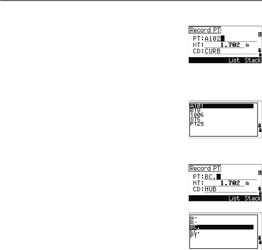
Trimble TS635 Construction Total Station User Guide 49
Getting Started 3
Entering a point from the point stack
The point stack is a list of the last 20 point names used,
in chronological order from last used to first used. To
enter a point from the point stack:
1. Select the Stack softkey when the cursor is in
the PT field. The stack appears.
2. Press [^] or [v] to move the cursor to the point that
you want to use.
3. Press [ENT].
When you return to the point input screen, the selected
point name is entered in the PT field, incremented by
one. For example, if you selected the A101 point, A102
appears in the PT field.
Entering a point from the point list
1. Select the List softkey when the cursor is in the
PT field. A list of existing points appears.
2. Press [^] or [v] to move the cursor to the point that
you want to use.
3. Press [ENT].
When you return to the point input screen, the selected
point name is entered in the PT field. Add numeric or
alphabetic characters if required.
Entering a code
The CD (Code) field defaults to the last code used. You can select a different code in the
input point screen.
Codenames can be numeric or alphanumeric, and up to 16 characters long.
There are several ways to enter a code:
•Enter a code directly, see page 50
•Enter a code from the code stack, see page 50
•Enter a code from the code list, see page 50
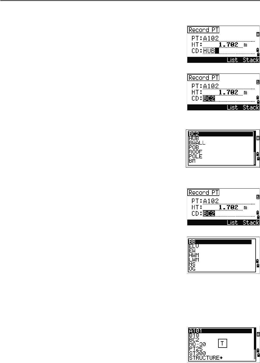
3 Getting Started
50 Trimble TS635 Construction Total Station User Guide
Entering a code directly
1. To change the input mode to alphanumeric or
numeric, press [MODE].
2. Use the keypad to enter the code.
Entering a code from the code stack
The code stack is a list of up to 20 recently used codes.
When you reboot the TS635 Construction Total Station,
the code stack is cleared.
To enter a code from the code stack:
1. Select the Stack softkey when the cursor is in
the CD field. The stack appears.
2. To move the cursor to the code that you want to
use, press [^] or [v].
3. Press [ENT].
The selected code is copied to the CD field.
Entering a code from the code list
1. Select the List softkey when the cursor is in the
CD field. A list of existing codes appear.
2. Press [^] or [v] to highlight the feature code that
you want to use.
3. Press [ENT].
A layer has an arrow at the end of the code label. If you
highlight a layer in the list and then press [ENT], the
codes and layers in that layer are displayed.
When you return to the input screen, the selected code
is entered in the CD field.
Advanced feature: Searching for a code using the first character
Items are shown in alphabetic order. To find a code quickly when the code list appears,
use the first-character search. For example, to see feature codes that begin with T, use
the keypad to enter the letter T (press [1] twice).
After each button press, the input mode field displays
the selected letter. For example, if you press [1], S
appears. If you quickly press [1] again, T appears. If you
do not press the [1] button again, the letter T is selected.
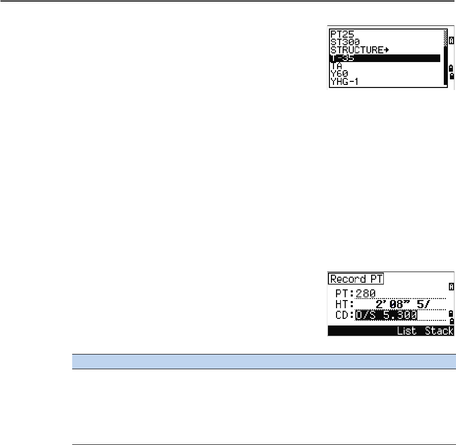
Trimble TS635 Construction Total Station User Guide 51
Getting Started 3
Once you select a letter, the cursor moves to the feature
code beginning with that letter.
If there is no code beginning with that letter, the cursor
moves to the next available letter.
Entering values in feet and inches
If US Survey Feet (US-Ft) or International Feet (I-Ft) is selected as the distance unit,
you can enter and display distances, HIs, HTs, and coordinate values in decimal feet or
in feet and inches. See also Unit, page 93, and Other settings, page 94.
To enter values in feet and inches in an input screen, enter the elements, separated by
periods (.), in the following format:
The default denominator is 16. If the denominator is 16, you do not have to enter it,
and it is not displayed on the screen.
For example, if you enter
[2] [.] [0] [8] [.] [5] [.] [ENT], it appears as 2'08" 5/ (2 feet, 8
and 5/16ths inches).
The following examples show how to enter various
values:
The numerator and denominator that you enter are automatically converted to the
closest value from the following list: 0, 1/8, 1/4, 3/8, 1/2, 5/8, 3/4, 7/8, 1/16, 3/16, 5/16,
7/16, 9/16, 11/16, 13/16, 15/16.
If the denominator is 16, it is not shown on the screen.
Creating or opening a job
To record data on the TS635 Construction Total Station, you must create or open a job.
Note – Before using the TS635 Construction Total Station for the first time, check that you
are using the required job settings.
<Feet> [.] <Inches> [.] <Numerator> [.] <Denominator> [ENT]
(0–11) (0–15) (0–99)
To enter... Key in...
65' 5 3/8" [6] [5] [.] [5] [.] [3] [.] [8] [ENT]
65' [6] [5] [ENT]
65' 5" [6] [5] [.] [5] [ENT]
65' 5 3/8" [6] [5] [.] [5] [.] [6] [ENT]
5 3/8" [0] [.] [5] [.] [3] [.] [8] [ENT] or [0] [.] [5] [.] [6] [ENT]
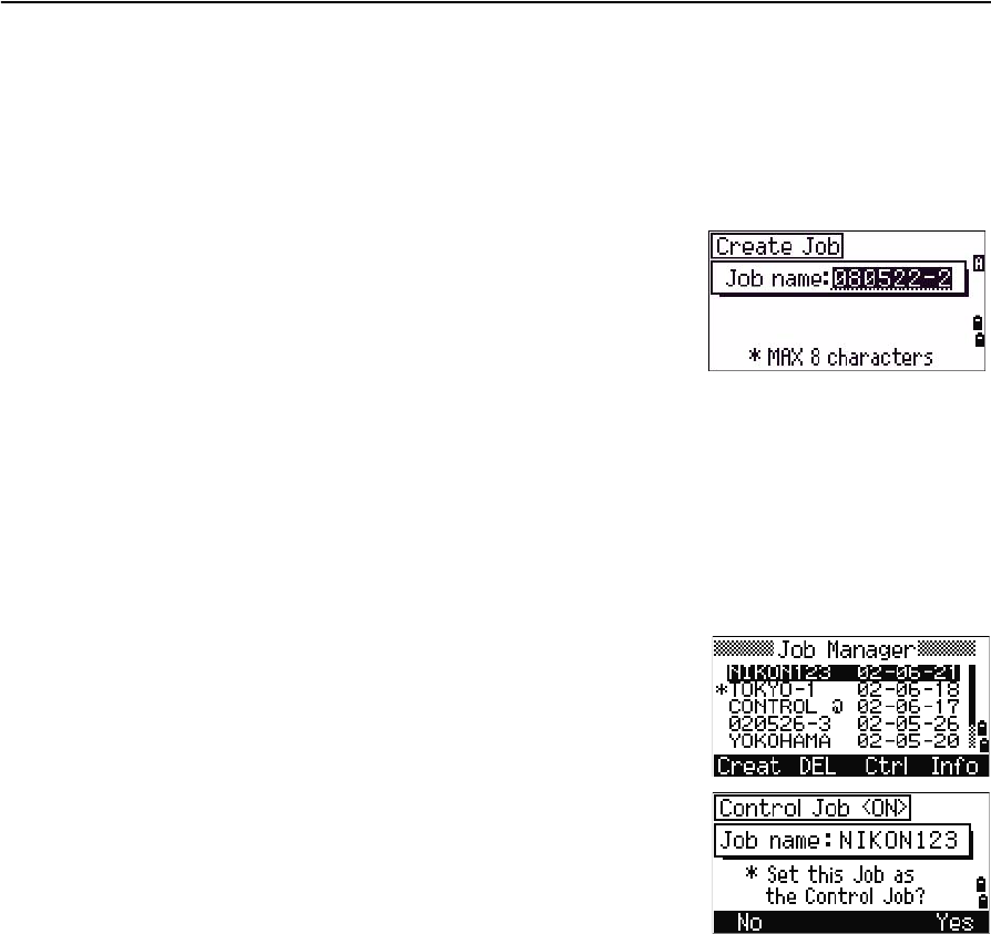
3 Getting Started
52 Trimble TS635 Construction Total Station User Guide
Creating a new job
1. Press [MENU]. The MENU screen appears.
2. Press [1]. The Job Manager appears.
3. Select the Creat softkey. The Create Job screen appears.
4. Enter the job name.
5. To check the job settings, select the Sett
softkey. You cannot change the settings for a job
once you have created the job.
6. Press [ENT] in the last field of the Job Sett screen.
The new job is created.
Note – You can only have a maximum of 32 jobs.
Creating a control job
A control job, or common file, stores coordinate data that is used by several field jobs.
To create a control job in the office:
1. Press [MENU]. The MENU screen appears.
2. Press [1] or select Job. The Job Manager appears.
3. Move the cursor to the job to use as the control
job.
4. Select the Ctrl softkey.
5. Select the Yes softkey.
When you enter a point name or number, the system
searches in the current job first. If the point is not found
in the current job, the search is automatically extended
to the control job. If the point is found in the control
job, the selected point is copied to the current job as a
UP record.
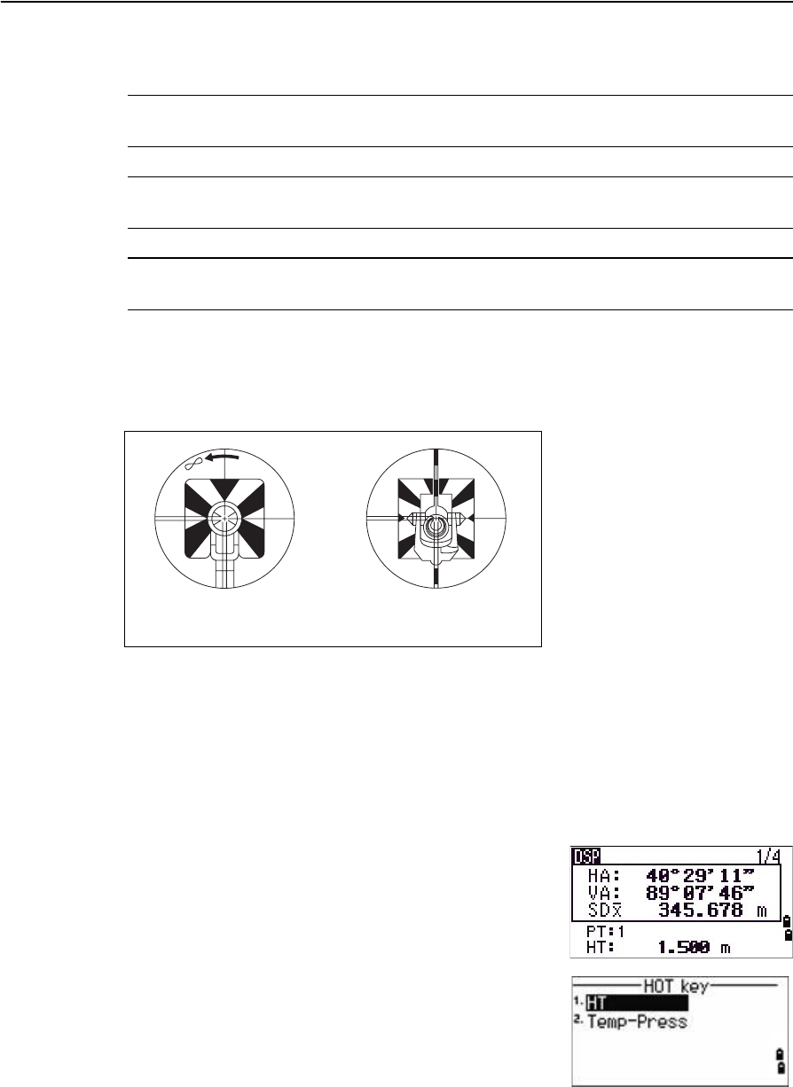
Trimble TS635 Construction Total Station User Guide 53
Getting Started 3
Measuring distances
CWARNING – Never look at the sun through the telescope. If you do, you may damage or
lose your eyesight.
C WARNING – Precautions should be taken to ensure that persons do not look directly, with
or without an optical instrument, into the beam.
CWARNING – Laser beam path should be located well above or below eye level wherever
practicable.
Sighting a prism reflector
Sight the telescope until you see cross-hairs at the center of the prism reflector.
Taking a distance measurement
To take a distance measurement, press [MSR1] or [MSR2] in the Basic Measurement Screen
(BMS) or in any observation screen.
While the instrument is taking a measurement, the prism constant appears in a
smaller font.
If tracking is set to ON, measurements are taken
continuously until you press [MSR1], [MSR2], or [ESC]. Each
time a measurement is taken, the distance is updated.
To change the height of target (HT), temperature, or
pressure, press [HOT]. See also [HOT] button, page 42.
Sighting a single prism Sighting a tiltable
single prism
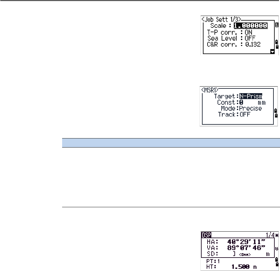
3 Getting Started
54 Trimble TS635 Construction Total Station User Guide
Settings that relate to corrections (T-P corr, Sea Level,
C&R corr., and Map projection) are included in the job
settings and are job-specific. To change any of these
settings, you must create a new job. See also Job,
page 86, and Settings (basic job settings), page 90.
Viewing and changing the measurement settings
1. Hold down [MSR1] or [MSR2] for one second.
2. To move the cursor between the fields, press [^] or
[v].
3. To change the value in the selected field, press [<]
or [>].
Target field
•If the measurement is started with the Target
field set to Prism, there is a dash “–” in front of
the prism constant.
•If the measurement is started with the Target
field set to N-Prism, there is a right square
bracket “]” in front of the prism constant.
The symbol then continuously moves from left to right over the prism constant
in the display.
The Target setting is used by the TS635 Construction Total Station to apply better
cyclic-error adjustment in distance measurement. The target setting efficiently
eliminates multipath reflection.
An incorrect Target setting may result in measurements outside the precision and
intervals specified for the instrument.
If you aim a prism target in the N-prism mode, the warning message Signal
High!→Try Prism Mode appears because of the excessive light reflection.
A measurement made immediately after changing the target setting may take a longer
time than usual.
Field Values
Target Prism
N-Prism
Const (prism constant) –999 mm through 999 mm
Mode Precise
Normal
Track Track (continuous MSR) ON
Track (continuous MSR) OFF