NIKON TRIMBLE NT0001 Bluetooth module User Manual TS635 manual 2
NIKON-TRIMBLE CO., LTD. Bluetooth module TS635 manual 2
Contents
Host 3 user manual 2 of 2

Trimble® TS635 Construction
Total Station
USER GUIDE
Part 2

NORTH AMERICA
Trimble Construction Division
5475 Kellenburger Road
Dayton, Ohio 45424
USA
800-538-7800 (Toll Free)
+1-937-245-5154 Phone
+1-937-233-9441 Fax
EUROPE
Trimble GmbH
Am Prime Parc 11
65479 Raunheim
GERMANY
+49-6142-2100-0 Phone
+49-6142-2100-550 Fax
ASIA-PACIFIC
Trimble Navigation
Singapore Pty Limited
80 Marine Parade Road
#22-06, Parkway Parade
Singapore 449269
SINGAPORE
+65-6348-2212 Phone
+65-6348-2232 Fax
www.trimble.com
Version 1.00
Revision A
February 2009
USER GUIDE
Trimble® TS635 Construction
Total Station
2 Trimble TS635 Construction Total Station User Guide
Corporate Office
Construction Division
5475 Kellenburger Road
Dayton, Ohio 45424-1099
USA
800-538-7800 (toll free in USA)
+1-937-245-5600 Phone
+1-937-233-9004 Fax
www.trimble.com
Legal Notices
Copyright and Trademarks
© 2006-2009, Nikon-Trimble Co. Limited. All rights reserved.
© 2007-2009, Trimble Navigation Limited. All rights reserved.
Trimble and the Globe & Triangle logo are trademarks of Trimble
Navigation Limited registered in the United States and in other
countries. Nikon is a registered trademark of the Nikon Corporation.
All other trademarks are the property of their respective owners.
Release Notice
This is the February 2009 release (Revision A) of the Trimble TS635
Construction Total Station User Guide. It applies to version 1.00 of the
TS635 construction total station.
Manufacturer
Nikon-Trimble Co., Ltd.
Technoport Mituiseimei Bldg.
16-2, Minamikamata 2-chome, Ota-ku
Tokyo 144-0035 Japan
Product Limited Warranty Information
For applicable product Limited Warranty information, please refer to the
Limited Warranty Card included with this Trimble product, or consult
your local Trimble authorized dealer.
Notices
Class B Statement – Notice to Users. This equipment has been tested
and found to comply with the limits for a Class B digital device, pursuant
to Part 15 of the FCC rules. These limits are designed to provide
reasonable protection against harmful interference in a residential
installation. This equipment generates, uses, and can radiate radio
frequency energy and, if not installed and used in accordance with the
instructions, may cause harmful interference to radio communication.
However, there is no guarantee that interference will not occur in a
particular installation. If this equipment does cause harmful
interference to radio or television reception, which can be determined
by turning the equipment off and on, the user is encouraged to try to
correct the interference by one or more of the following measures:
– Reorient or relocate the receiving antenna.
– Increase the separation between the equipment and the receiver.
– Connect the equipment into an outlet on a circuit different from that
to which the receiver is connected.
– Consult the dealer or an experienced radio/TV technician for help.
Changes and modifications not expressly approved by the manufacturer
or registrant of this equipment can void your authority to operate this
equipment under Federal Communications Commission rules.
CWARNING - This equipment has been certified to comply with the
limits for a Class B personal computer and peripherals, pursuant to
Subpart B of Part 15 of FCC Rules. Only peripherals (computer
input/output devices, terminals, printers, etc.) certified to comply with
the Class B limits may be attached to this equipment. Operation with
non-certified personal computer and/or peripherals is likely to result in
interference to radio and TV reception. The connection of a non-
shielded equipment interface cable to this equipment will invalidate
the FCC Certification of this device and may cause interference levels
which exceed the limits established by the FCC for this equipment.
You are cautioned that changes or modifications not expressly
approved by the party responsible for compliance could void your
authority to operate the equipment.
Canada
This digital apparatus does not exceed the Class B limits for radio noise
emissions from digital apparatus as set out in the radio interference
regulations of the Canadian Department of Communications.
Le présent appareil numérique n’émet pas de bruits radioélectriques
dépassant les limites applicables aux appareils numériques de Classe B
prescrites dans le règlement sur le brouillage radioélectrique édicté par
le Ministère des Communications du Canada.
Europe
This product has been tested and found to comply with the
requirements for a Class B device pursuant to European
Council Directive 2004/108/EC on EMC, thereby satisfying the
requirements for CE Marking and sale within the European Economic
Area (EEA). These requirements are designed to provide reasonable
protection against harmful interference when the equipment is operated
in a residential or commercial environment.
Representative in Europe
Trimble GmbH
Am Prime Parc 11
65479 Raunheim, Germany
Australia and New Zealand
This product conforms with the regulatory requirements of the
Australian Communications Authority (ACA) EMC framework,
thus satisfying the requirements for C-Tick Marking and sale
within Australia and New Zealand.
Taiwan Battery Recycling Requirements
The product contains a removable Ni-MH battery.
Taiwanese regulations require that waste batteries are
recycled.
Notice to Our European Union Customers
For product recycling instructions and more information, please
go to: www.trimble.com/environment/summary.html.
Recycling in Europe
To recycle Trimble WEEE, call: +31 497 53 2430, and ask for the
"WEEE associate," or mail a request for recycling instructions to:
Trimble Europe BV
c/o Menlo Worldwide Logistics
Meerheide 45
5521 DZ Eersel, NL
For the Bluetooth unit
USA
FCC Part 15 Subpart/RSS-210, OET bulletin 65 supplement C satisfied
CAUTION: Any changes or modifications not expressly approved by the
party responsible for compliance could void the user's authority to
operate the equipment.
NOTE: This equipment has been tested and found to comply with the limits
for a Class B digital device, pursuant to part 15 of the FCC Rules. These
limits are designed to provide reasonable protection against harmful
interference in a residential installation. This equipment generates, uses
and can radiate radio frequency energy and, if not installed and used in
accordance with the instructions, may cause harmful interference to radio
communications. However, there is no guarantee that interference will not
occur in a particular installation. If this equipment does cause harmful
interference to radio or television reception, which can be determined by
turning the equipment off and on, the user is encouraged to try to correct
the interference by one or more of the following measures:
-Reorient or relocate the receiving antenna.
-Increase the separation between the equipment and receiver.
-Connect the equipment into an outlet on a circuit different from that to
which the
receiver is connected.
-Consult the dealer or an experienced radio/TV technician for help.
Canada
RSS-210 Low Power Device
Operation is subject to the following two conditions: (1) This device may
not cause interference, and (2) this device must accept any interference,
including interference that may cause undesired operation of the device.
European Union countries, Iceland, Norway, Liechtenstein, Turkey,
Switzerland
EN300 328v17.1, EN50360 satisfied
Hereby, Nikon-Trimble Co., Ltd., declares that this instrument is in
compliance with the essential requirements and other relevant
provisions of Directive 1999/5/EC.
Declaration of Conformity available at http://www.nikon-trimble.com/.
RF exposure compliance
1. To comply with FCC/IC RF exposure compliance requirements, a
separation distance of at least 20 cm must be maintained between the
antenna of this device and all persons.
2. This transmitter must not be co-located or operated in conjunction
with any other antenna or transmitter.
Trimble TS635 Construction Total Station User Guide 3
Contents 1
Safety . . . . . . . . . . . . . . . . . . . . . . . . . . . . . . . . . . . . . . . . 7
Warnings and Cautions . . . . . . . . . . . . . . . . . . . . . . . . . . . . . . . . . . . . . . . . . . . . . . 7
Rechargeable Lithium-ion (Li-ion) batteries . . . . . . . . . . . . . . . . . . . . . . . . . . . . . 7
Warnings . . . . . . . . . . . . . . . . . . . . . . . . . . . . . . . . . . . . . . . . . . . . . . . . . . . 8
Cautions . . . . . . . . . . . . . . . . . . . . . . . . . . . . . . . . . . . . . . . . . . . . . . . . . . . 9
Laser safety . . . . . . . . . . . . . . . . . . . . . . . . . . . . . . . . . . . . . . . . . . . . . . . . . . . . . 10
Specifications for laser emission . . . . . . . . . . . . . . . . . . . . . . . . . . . . . . . . . . . 10
Conforming standards . . . . . . . . . . . . . . . . . . . . . . . . . . . . . . . . . . . . . . . . . 11
Labels . . . . . . . . . . . . . . . . . . . . . . . . . . . . . . . . . . . . . . . . . . . . . . . . . . . . 11
1 Introduction . . . . . . . . . . . . . . . . . . . . . . . . . . . . . . . . . . . 13
System diagram . . . . . . . . . . . . . . . . . . . . . . . . . . . . . . . . . . . . . . . . . . . . . . . . . . 14
Care and maintenance. . . . . . . . . . . . . . . . . . . . . . . . . . . . . . . . . . . . . . . . . . . . . . 15
Storage . . . . . . . . . . . . . . . . . . . . . . . . . . . . . . . . . . . . . . . . . . . . . . . . . . . 15
Environmental conditions . . . . . . . . . . . . . . . . . . . . . . . . . . . . . . . . . . . . . . . 15
Cleaning . . . . . . . . . . . . . . . . . . . . . . . . . . . . . . . . . . . . . . . . . . . . . . . . . . 16
Adjusting and tightening . . . . . . . . . . . . . . . . . . . . . . . . . . . . . . . . . . . . . . . . 16
Related information . . . . . . . . . . . . . . . . . . . . . . . . . . . . . . . . . . . . . . . . . . . . . . . 17
2 Setting up the Instrument . . . . . . . . . . . . . . . . . . . . . . . . . . . 19
Unpacking and repacking the instrument . . . . . . . . . . . . . . . . . . . . . . . . . . . . . . . . . 20
Charging the battery pack . . . . . . . . . . . . . . . . . . . . . . . . . . . . . . . . . . . . . . . . . . . 20
Applying power . . . . . . . . . . . . . . . . . . . . . . . . . . . . . . . . . . . . . . . . . . . . . . 22
Charging the battery. . . . . . . . . . . . . . . . . . . . . . . . . . . . . . . . . . . . . . . . . . . 22
Conditioning / calibrating a battery . . . . . . . . . . . . . . . . . . . . . . . . . . . . . . . . . 23
Detaching the battery pack . . . . . . . . . . . . . . . . . . . . . . . . . . . . . . . . . . . . . . 23
Attaching the battery pack . . . . . . . . . . . . . . . . . . . . . . . . . . . . . . . . . . . . . . . 24
Setting up the tripod . . . . . . . . . . . . . . . . . . . . . . . . . . . . . . . . . . . . . . . . . . . . . . . 25
Centering the instrument . . . . . . . . . . . . . . . . . . . . . . . . . . . . . . . . . . . . . . . . . . . . 26
Centering with the optical plummet. . . . . . . . . . . . . . . . . . . . . . . . . . . . . . . . . 26
Centering with the laser plummet . . . . . . . . . . . . . . . . . . . . . . . . . . . . . . . . . . 26
Centering with a plumb bob . . . . . . . . . . . . . . . . . . . . . . . . . . . . . . . . . . . . . . 27
Leveling the instrument . . . . . . . . . . . . . . . . . . . . . . . . . . . . . . . . . . . . . . . . . . . . . 28
Focusing the telescope. . . . . . . . . . . . . . . . . . . . . . . . . . . . . . . . . . . . . . . . . . . . . . 29
Setting the measurement mode and preparing the target . . . . . . . . . . . . . . . . . . . . . . . 30
Measurement with a prism. . . . . . . . . . . . . . . . . . . . . . . . . . . . . . . . . . . . . . . 30
Measurement in reflectorless (N-Prism) mode . . . . . . . . . . . . . . . . . . . . . . . . . . 31
Viewing and changing the measurement settings. . . . . . . . . . . . . . . . . . . . . . . . . . . . . 32
Target field . . . . . . . . . . . . . . . . . . . . . . . . . . . . . . . . . . . . . . . . . . . . . . . . . 32
Prism constant . . . . . . . . . . . . . . . . . . . . . . . . . . . . . . . . . . . . . . . . . . . . . . 32
3 Getting Started. . . . . . . . . . . . . . . . . . . . . . . . . . . . . . . . . . 33
Instrument keyboard and display . . . . . . . . . . . . . . . . . . . . . . . . . . . . . . . . . . . . . . 36
Instrument keyboard . . . . . . . . . . . . . . . . . . . . . . . . . . . . . . . . . . . . . . . . . . 36
Status bar. . . . . . . . . . . . . . . . . . . . . . . . . . . . . . . . . . . . . . . . . . . . . . . . . . 37

4 Trimble TS635 Construction Total Station User Guide
LCD backlight, laser pointer, beep sound, and contrast adjustment . . . . . . . . . . . . . 39
[DSP] button. . . . . . . . . . . . . . . . . . . . . . . . . . . . . . . . . . . . . . . . . . . . . . . . 40
[MODE] button . . . . . . . . . . . . . . . . . . . . . . . . . . . . . . . . . . . . . . . . . . . . . . 41
[HOT] key . . . . . . . . . . . . . . . . . . . . . . . . . . . . . . . . . . . . . . . . . . . . . . . . . 42
Bubble indicator . . . . . . . . . . . . . . . . . . . . . . . . . . . . . . . . . . . . . . . . . . . . . 42
Laser plummet . . . . . . . . . . . . . . . . . . . . . . . . . . . . . . . . . . . . . . . . . . . . . . 43
Turning on the instrument . . . . . . . . . . . . . . . . . . . . . . . . . . . . . . . . . . . . . . . . . . . 44
Turning off the instrument . . . . . . . . . . . . . . . . . . . . . . . . . . . . . . . . . . . . . . . . . . . 44
Sleep mode. . . . . . . . . . . . . . . . . . . . . . . . . . . . . . . . . . . . . . . . . . . . . . . . . 44
Regional configuration. . . . . . . . . . . . . . . . . . . . . . . . . . . . . . . . . . . . . . . . . . . . . . 45
List available jobs or data . . . . . . . . . . . . . . . . . . . . . . . . . . . . . . . . . . . . . . . . . . . . 46
Entering data. . . . . . . . . . . . . . . . . . . . . . . . . . . . . . . . . . . . . . . . . . . . . . . . . . . . 46
Entering a point name or number . . . . . . . . . . . . . . . . . . . . . . . . . . . . . . . . . . 46
Entering a code . . . . . . . . . . . . . . . . . . . . . . . . . . . . . . . . . . . . . . . . . . . . . . 49
Entering values in feet and inches . . . . . . . . . . . . . . . . . . . . . . . . . . . . . . . . . . 51
Creating or opening a job . . . . . . . . . . . . . . . . . . . . . . . . . . . . . . . . . . . . . . . . . . . . 51
Creating a new job . . . . . . . . . . . . . . . . . . . . . . . . . . . . . . . . . . . . . . . . . . . . 52
Creating a control job . . . . . . . . . . . . . . . . . . . . . . . . . . . . . . . . . . . . . . . . . . 52
Measuring distances . . . . . . . . . . . . . . . . . . . . . . . . . . . . . . . . . . . . . . . . . . . . . . . 53
Sighting a prism reflector. . . . . . . . . . . . . . . . . . . . . . . . . . . . . . . . . . . . . . . . 53
Taking a distance measurement . . . . . . . . . . . . . . . . . . . . . . . . . . . . . . . . . . . 53
Viewing and changing the measurement settings . . . . . . . . . . . . . . . . . . . . . . . . 54
4 Applications . . . . . . . . . . . . . . . . . . . . . . . . . . . . . . . . . . . 55
HA reset and angle operations. . . . . . . . . . . . . . . . . . . . . . . . . . . . . . . . . . . . . . . . . 56
Setting the horizontal angle to 0 . . . . . . . . . . . . . . . . . . . . . . . . . . . . . . . . . . . 56
Entering the horizontal angle . . . . . . . . . . . . . . . . . . . . . . . . . . . . . . . . . . . . . 56
Station setup . . . . . . . . . . . . . . . . . . . . . . . . . . . . . . . . . . . . . . . . . . . . . . . . . . . . 56
Baseline . . . . . . . . . . . . . . . . . . . . . . . . . . . . . . . . . . . . . . . . . . . . . . . . . . . 57
Known. . . . . . . . . . . . . . . . . . . . . . . . . . . . . . . . . . . . . . . . . . . . . . . . . . . . 58
Base XYZ . . . . . . . . . . . . . . . . . . . . . . . . . . . . . . . . . . . . . . . . . . . . . . . . . . 60
Remote BM . . . . . . . . . . . . . . . . . . . . . . . . . . . . . . . . . . . . . . . . . . . . . . . . 60
BS Check . . . . . . . . . . . . . . . . . . . . . . . . . . . . . . . . . . . . . . . . . . . . . . . . . . 61
Layout menu . . . . . . . . . . . . . . . . . . . . . . . . . . . . . . . . . . . . . . . . . . . . . . . . . . . . 62
L-O to Point . . . . . . . . . . . . . . . . . . . . . . . . . . . . . . . . . . . . . . . . . . . . . . . . 62
L-O from Line . . . . . . . . . . . . . . . . . . . . . . . . . . . . . . . . . . . . . . . . . . . . . . . 63
L-O from Arc. . . . . . . . . . . . . . . . . . . . . . . . . . . . . . . . . . . . . . . . . . . . . . . . 64
XYZ . . . . . . . . . . . . . . . . . . . . . . . . . . . . . . . . . . . . . . . . . . . . . . . . . . . . . 65
Programs menu . . . . . . . . . . . . . . . . . . . . . . . . . . . . . . . . . . . . . . . . . . . . . . . . . . 67
Remote distance measurement (RDM) - overview . . . . . . . . . . . . . . . . . . . . . . . . 68
RDM (Radial) . . . . . . . . . . . . . . . . . . . . . . . . . . . . . . . . . . . . . . . . . . . . . . . 69
RDM (Cont) . . . . . . . . . . . . . . . . . . . . . . . . . . . . . . . . . . . . . . . . . . . . . . . . 69
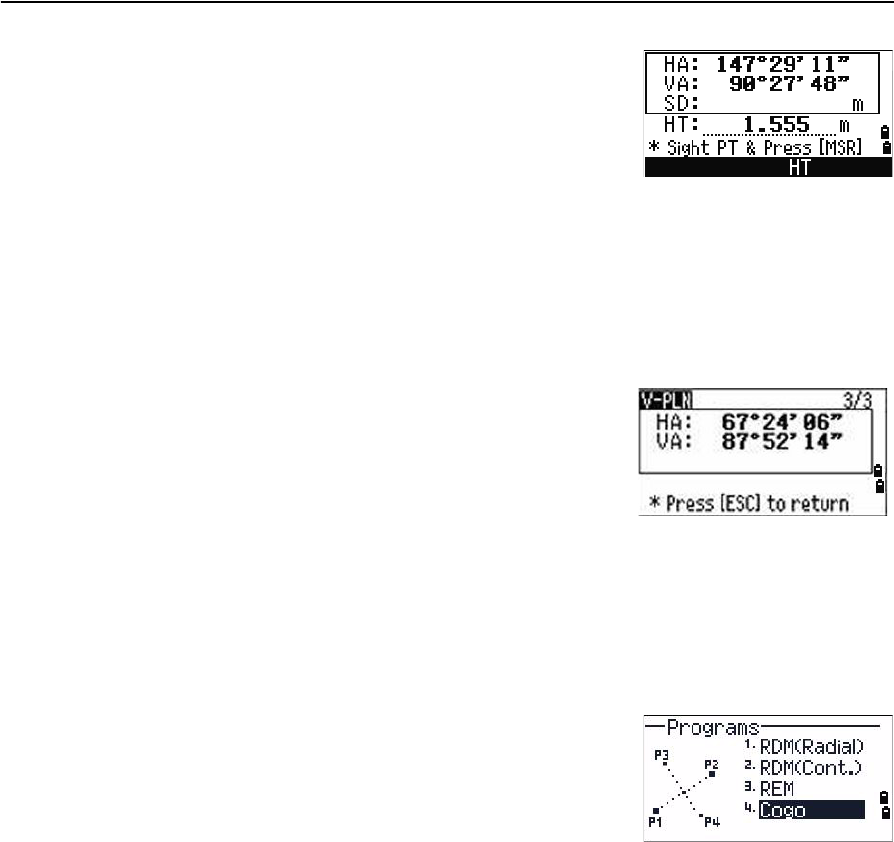
REM . . . . . . . . . . . . . . . . . . . . . . . . . . . . . . . . . . . . . . . . . . . . . . . . . . . . . 70
V-Plane . . . . . . . . . . . . . . . . . . . . . . . . . . . . . . . . . . . . . . . . . . . . . . . . . . . 70
Cogo . . . . . . . . . . . . . . . . . . . . . . . . . . . . . . . . . . . . . . . . . . . . . . . . . . . . . 71
Recording measurement data . . . . . . . . . . . . . . . . . . . . . . . . . . . . . . . . . . . . . . . . . 83

Trimble TS635 Construction Total Station User Guide 5
Switching between display screens . . . . . . . . . . . . . . . . . . . . . . . . . . . . . . . . . . . . . . 83
5 Menu Screen . . . . . . . . . . . . . . . . . . . . . . . . . . . . . . . . . . . 85
Job . . . . . . . . . . . . . . . . . . . . . . . . . . . . . . . . . . . . . . . . . . . . . . . . . . . . . . . . . . 86
Opening an existing job . . . . . . . . . . . . . . . . . . . . . . . . . . . . . . . . . . . . . . . . . 86
Creating a new job . . . . . . . . . . . . . . . . . . . . . . . . . . . . . . . . . . . . . . . . . . . . 86
Deleting a job . . . . . . . . . . . . . . . . . . . . . . . . . . . . . . . . . . . . . . . . . . . . . . . 88
Setting the control job. . . . . . . . . . . . . . . . . . . . . . . . . . . . . . . . . . . . . . . . . . 89
Displaying job information. . . . . . . . . . . . . . . . . . . . . . . . . . . . . . . . . . . . . . . 89
Settings (basic job settings). . . . . . . . . . . . . . . . . . . . . . . . . . . . . . . . . . . . . . . . . . . 90
Angle . . . . . . . . . . . . . . . . . . . . . . . . . . . . . . . . . . . . . . . . . . . . . . . . . . . . 90
Distance . . . . . . . . . . . . . . . . . . . . . . . . . . . . . . . . . . . . . . . . . . . . . . . . . . 90
Coordinate . . . . . . . . . . . . . . . . . . . . . . . . . . . . . . . . . . . . . . . . . . . . . . . . . 93
Communications . . . . . . . . . . . . . . . . . . . . . . . . . . . . . . . . . . . . . . . . . . . . . 93
Unit . . . . . . . . . . . . . . . . . . . . . . . . . . . . . . . . . . . . . . . . . . . . . . . . . . . . . 93
Power saving. . . . . . . . . . . . . . . . . . . . . . . . . . . . . . . . . . . . . . . . . . . . . . . . 94
Recording. . . . . . . . . . . . . . . . . . . . . . . . . . . . . . . . . . . . . . . . . . . . . . . . . . 94
Other settings . . . . . . . . . . . . . . . . . . . . . . . . . . . . . . . . . . . . . . . . . . . . . . . 94
Data . . . . . . . . . . . . . . . . . . . . . . . . . . . . . . . . . . . . . . . . . . . . . . . . . . . . . . . . . 95
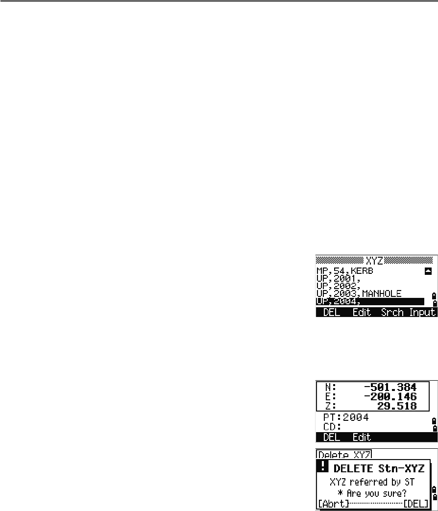
Viewing coordinate data . . . . . . . . . . . . . . . . . . . . . . . . . . . . . . . . . . . . . . . . 95
UP, MP, CC, SS, and SO records . . . . . . . . . . . . . . . . . . . . . . . . . . . . . . . . . . . . 96
Deleting coordinate records . . . . . . . . . . . . . . . . . . . . . . . . . . . . . . . . . . . . . . 96
Editing coordinate records . . . . . . . . . . . . . . . . . . . . . . . . . . . . . . . . . . . . . . . 96
Searching coordinate records . . . . . . . . . . . . . . . . . . . . . . . . . . . . . . . . . . . . . 97
Entering coordinates . . . . . . . . . . . . . . . . . . . . . . . . . . . . . . . . . . . . . . . . . . 98
Communication . . . . . . . . . . . . . . . . . . . . . . . . . . . . . . . . . . . . . . . . . . . . . . . . . . 99
Downloading coordinate data. . . . . . . . . . . . . . . . . . . . . . . . . . . . . . . . . . . . . 99
Uploading coordinate data . . . . . . . . . . . . . . . . . . . . . . . . . . . . . . . . . . . . . . . 99
1sec-Key. . . . . . . . . . . . . . . . . . . . . . . . . . . . . . . . . . . . . . . . . . . . . . . . . . . . . . .101
[MSR] button settings . . . . . . . . . . . . . . . . . . . . . . . . . . . . . . . . . . . . . . . . . .101
[DSP] button settings . . . . . . . . . . . . . . . . . . . . . . . . . . . . . . . . . . . . . . . . . .101
Calibration . . . . . . . . . . . . . . . . . . . . . . . . . . . . . . . . . . . . . . . . . . . . . . . . . . . . .102
Time . . . . . . . . . . . . . . . . . . . . . . . . . . . . . . . . . . . . . . . . . . . . . . . . . . . . . . . . .102
6 Checking and Adjusting . . . . . . . . . . . . . . . . . . . . . . . . . . . . 103
Adjusting the electronic level . . . . . . . . . . . . . . . . . . . . . . . . . . . . . . . . . . . . . . . . .104
Checking and adjusting the circular level . . . . . . . . . . . . . . . . . . . . . . . . . . . . . . . . . .104
Checking and adjusting the optical/laser plummet. . . . . . . . . . . . . . . . . . . . . . . . . . . .104
Zero point errors of vertical scale and horizontal angle corrections . . . . . . . . . . . . . . . . .105
Checking the calibration . . . . . . . . . . . . . . . . . . . . . . . . . . . . . . . . . . . . . . . .105
Adjusting the calibration . . . . . . . . . . . . . . . . . . . . . . . . . . . . . . . . . . . . . . . .106
The instrument constant . . . . . . . . . . . . . . . . . . . . . . . . . . . . . . . . . . . . . . . . . . . .107
Checking and adjusting the laser pointer . . . . . . . . . . . . . . . . . . . . . . . . . . . . . . . . . .108
A Specifications. . . . . . . . . . . . . . . . . . . . . . . . . . . . . . . . . . 109
Main body. . . . . . . . . . . . . . . . . . . . . . . . . . . . . . . . . . . . . . . . . . . . . . . . . . . . . .110

6 Trimble TS635 Construction Total Station User Guide
Telescope . . . . . . . . . . . . . . . . . . . . . . . . . . . . . . . . . . . . . . . . . . . . . . . . . .110
Measurement range . . . . . . . . . . . . . . . . . . . . . . . . . . . . . . . . . . . . . . . . . . .110
Distance precision . . . . . . . . . . . . . . . . . . . . . . . . . . . . . . . . . . . . . . . . . . . .111
Measurement intervals . . . . . . . . . . . . . . . . . . . . . . . . . . . . . . . . . . . . . . . . .111
Angle measurement . . . . . . . . . . . . . . . . . . . . . . . . . . . . . . . . . . . . . . . . . . .112
Tilt sensor . . . . . . . . . . . . . . . . . . . . . . . . . . . . . . . . . . . . . . . . . . . . . . . . .112
Tangent screws . . . . . . . . . . . . . . . . . . . . . . . . . . . . . . . . . . . . . . . . . . . . . .112
Tribrach. . . . . . . . . . . . . . . . . . . . . . . . . . . . . . . . . . . . . . . . . . . . . . . . . . .112
Level . . . . . . . . . . . . . . . . . . . . . . . . . . . . . . . . . . . . . . . . . . . . . . . . . . . . .112
Optical plumment (Optional) . . . . . . . . . . . . . . . . . . . . . . . . . . . . . . . . . . . . .112
Laser plummet . . . . . . . . . . . . . . . . . . . . . . . . . . . . . . . . . . . . . . . . . . . . . .113
Display and keypad . . . . . . . . . . . . . . . . . . . . . . . . . . . . . . . . . . . . . . . . . . .113
Connections in the base of instrument . . . . . . . . . . . . . . . . . . . . . . . . . . . . . . .113
Battery pack . . . . . . . . . . . . . . . . . . . . . . . . . . . . . . . . . . . . . . . . . . . . . . . .113
Environmental performance. . . . . . . . . . . . . . . . . . . . . . . . . . . . . . . . . . . . . .114
Dimensions . . . . . . . . . . . . . . . . . . . . . . . . . . . . . . . . . . . . . . . . . . . . . . . .114
Weight. . . . . . . . . . . . . . . . . . . . . . . . . . . . . . . . . . . . . . . . . . . . . . . . . . . .114
Environmental protection . . . . . . . . . . . . . . . . . . . . . . . . . . . . . . . . . . . . . . .114
Standard components . . . . . . . . . . . . . . . . . . . . . . . . . . . . . . . . . . . . . . . . . . . . . .114
External device connector . . . . . . . . . . . . . . . . . . . . . . . . . . . . . . . . . . . . . . . . . . .115
B Transferring Coordinate Data . . . . . . . . . . . . . . . . . . . . . . . . 117
Transferring coordinate data to the total station . . . . . . . . . . . . . . . . . . . . . . . . . . . . .118
Settings . . . . . . . . . . . . . . . . . . . . . . . . . . . . . . . . . . . . . . . . . . . . . . . . . . .118
Record format . . . . . . . . . . . . . . . . . . . . . . . . . . . . . . . . . . . . . . . . . . . . . . .118
Data example . . . . . . . . . . . . . . . . . . . . . . . . . . . . . . . . . . . . . . . . . . . . . . .119
Transferring coordinate data from the total station . . . . . . . . . . . . . . . . . . . . . . . . . . .119
Settings . . . . . . . . . . . . . . . . . . . . . . . . . . . . . . . . . . . . . . . . . . . . . . . . . . .119
Data examples. . . . . . . . . . . . . . . . . . . . . . . . . . . . . . . . . . . . . . . . . . . . . . .119
C Error Messages . . . . . . . . . . . . . . . . . . . . . . . . . . . . . . . . . 121
Cogo . . . . . . . . . . . . . . . . . . . . . . . . . . . . . . . . . . . . . . . . . . . . . . . . . . . . . . . . .122
Communications . . . . . . . . . . . . . . . . . . . . . . . . . . . . . . . . . . . . . . . . . . . . . . . . .122
Data . . . . . . . . . . . . . . . . . . . . . . . . . . . . . . . . . . . . . . . . . . . . . . . . . . . . . . . . .123
Job manager . . . . . . . . . . . . . . . . . . . . . . . . . . . . . . . . . . . . . . . . . . . . . . . . . . . .123
Layout . . . . . . . . . . . . . . . . . . . . . . . . . . . . . . . . . . . . . . . . . . . . . . . . . . . . . . . .124
Programs . . . . . . . . . . . . . . . . . . . . . . . . . . . . . . . . . . . . . . . . . . . . . . . . . . . . . .124
Recording data. . . . . . . . . . . . . . . . . . . . . . . . . . . . . . . . . . . . . . . . . . . . . . . . . . .125
Searching . . . . . . . . . . . . . . . . . . . . . . . . . . . . . . . . . . . . . . . . . . . . . . . . . . . . . .126
Settings . . . . . . . . . . . . . . . . . . . . . . . . . . . . . . . . . . . . . . . . . . . . . . . . . . . . . . .126
Station setup . . . . . . . . . . . . . . . . . . . . . . . . . . . . . . . . . . . . . . . . . . . . . . . . . . . .127
System error . . . . . . . . . . . . . . . . . . . . . . . . . . . . . . . . . . . . . . . . . . . . . . . . . . . .127

CHAPTER
4
Trimble TS635 Construction Total Station User Guide 55
Applications 4
In this chapter:
QHA reset and angle operations
QStation setup
QLayout menu
QPrograms menu
QRecording measurement data
QSwitching between display
screens
This chapter describes the menu and display
screens, and TS635 Construction Total Station
applications.
Use the following keystrokes when working in
the display screens and when you use the
applications:
To switch between
display screens
Press [DSP]. See also
page 83.
To change HT Press [HOT]
To record points Press [ENT]
4 Applications
56 Trimble TS635 Construction Total Station User Guide
HA reset and angle operations
To access the Angle menu, press [ANG] in the Basic
Measurement Screen (BMS). To select a command from
the Angle menu, press the corresponding number key.
Alternatively, press [^] or [v] to highlight the command
and then press [ENT].
Setting the horizontal angle to 0
Press [1] or select 0-Set in the Angle menu. The display returns to the BMS.
Entering the horizontal angle
1. Press [2] or select Input in the Angle menu. The
HA Input screen appears.
2. Use the numeric keys to enter the horizontal
angle.
3. Press [ENT].
To enter 123°45'50", key in [1] [2] [3] [.] [4] [5] [5] [0].
The displayed value is rounded to the minimum angle increment.
Station setup
To access the Stn Setup menu, press [STN] in the BMS.
To select a command from the Stn Setup menu, press
the corresponding number key. Alternatively, press [^] or
[v] to highlight the command and then press [ENT].
The last function used is highlighted.
The station setup options are:
•Baseline, page 57
•Known, page 58
•Base XYZ, page 60
•Remote BM, page 60
•BS Check, page 61
Trimble TS635 Construction Total Station User Guide 57
Applications 4
Baseline
Select this option for a two-point resection along a known line.
1. Press [1] or select BaseLine from the Stn Setup
menu.
2. Enter a known point as P1.
If you enter a new point name, a coordinate input
screen appears.
Sight P1 and press [MSR1] or [MSR2] to take a
measurement. Press [ENT].
3. Choose how you want to define a known line:
–To define the line by entering P2
coordinates, press [1] or select By Coord.
–To define the line by entering the azimuth,
press [2] or select By Angle.
a. If you select By Angle, the azimuth input
screen appears: Enter the angle value and
press [ENT].
A measurement screen appears.
b. Sight P2 and press [MSR1] or [MSR2] to take a
measurement. Press [ENT].
After the measurement to P2 is completed,
press [ENT]. The coordinates of the station are
calculated.
4. To record the station, press [ENT] or the REC
softkey.
5. To check the measurement, press the DSP
softkey. If you defined the line by entering its
azimuth, the HD and VD between P1 and P2 are
displayed.
If you defined the line by entering the P2
coordinates, the difference of HD (dHD) and VD
(dZ) between your measurement data and input
coordinate data are displayed.
4 Applications
58 Trimble TS635 Construction Total Station User Guide
6. Enter the station name, the height of instrument
(HI), and a feature code (CD) if required. The
station name defaults to the last recorded PT + 1.
7. Backsight (BS) defaults to the first point (P1). To
change the selected point, highlight the BS field
and then select the Change softkey.
8. To finish the setup and record the station, press
[ENT] in the BS field.
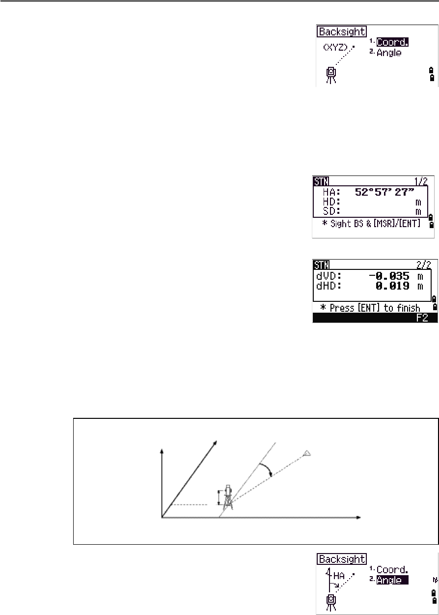
Known
Select this option to set up a station with known coordinates or azimuth.
1. Press [2] or select Known in the Stn Setup menu.
2. Enter a point name or number in the ST field.
–If the input point number or name is an
existing point, its coordinates are displayed
and the cursor moves to the HI (Height of
instrument) field.
–If the point is new, a coordinate input screen appears. Enter the
coordinates for the point. Press [ENT] after each field. When you press [ENT] in
the CD field, the new point is stored.
–If the specified point has a code, the code appears in the CD field.
3. Enter the instrument height in the HI field and then press [ENT].
4. In the Backsight screen that appears, select an input method for defining the
backsight point:
–To sight the backsight by entering coordinates, see the following section.
–To sight the backsight by entering the azimuth and angle, see page 59.
Sighting the backsight by entering coordinates
Z
Y
X0
X
Xb
Y0 Yb
Backsight point
(Xb, Yb, Zb)
Station point
(Xi, Yi, Zi)
Instrument height
Trimble TS635 Construction Total Station User Guide 59
Applications 4
1. To enter coordinates for the backsight point (BS),
press [1] or select Coord from the Backsight
screen.
2. Enter the point name. If the point exists in the
job, its coordinates are shown.
3. If you intend to take a distance measurement to
the BS, enter the height of target in the HT field.
4. Sight the BS, and then press [ENT] to complete the
setup.
If measuring to a known coordinate BS, press
[DSP] to display a QA screen. The QA screen shows
the dHD and dVD values, which indicate the
difference between the measured distance and
the distance calculated from the known
coordinates.
5. To record the station, press [ENT].
6. To finish the station setup after taking a distance measurement, press [ENT].
Sighting the backsight by entering the azimuth angle
1. To enter the azimuth angle to the backsight
point, press [2] or select Angle from the
Backsight screen.
2. If there is no point name for the BS, press [ENT] on
the BS field.
HA Azimuth calculated by
coordinates
Backsight point
Azimuth
Station point
(Xi, Yi, Zi)
Instrument height
X
Y0
Y
4 Applications
60 Trimble TS635 Construction Total Station User Guide
3. In the HA field, enter the azimuth angle to the BS point.
If you press [ENT] without entering a value in the HA field, the azimuth is
automatically set to 0°00'00".
4. Sight the BS point and press [ENT].
Base XYZ
Select this option to change the instrument XYZ values.
Base XYZ does not store an ST record in the job, so the BS Check cannot check the
backsight if you enter a station using the Base XYZ option.
You can use this function without an open job.
1. Press [3] or select Base XYZ from the Stn Setup
menu.
The current instrument XYZ values are shown as
the default.
2. Enter the new instrument XYZ values and then
press [ENT].
3. Do one of the following:
–To reset the horizontal angle, enter a value in the HA field and then press
[ENT].
–If you do not need to reset the horizontal angle, leave the HA field blank
and then press [ENT].
The Stn Setup menu appears.
Remote BM
Select this option to determine the station elevation.
1. Press [4] or select Remote BM from the Stn
Setup menu.
2. Enter the BM point and press [ENT]. The point
appears briefly. The cursor then moves to the HT
field.
3. Enter the HT and then press [ENT].
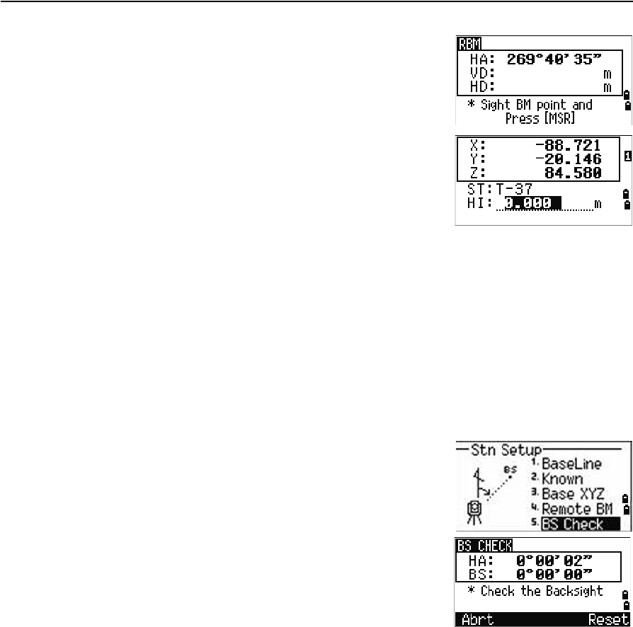
Trimble TS635 Construction Total Station User Guide 61
Applications 4
4. Sight the Bench Mark point and then press [MSR1]
or [MSR2].
The updated station coordinates are displayed.
You can change the HI in this screen.
5. To record the updated STN, press [ENT].
When the HI setting is changed, the Z coordinate is
updated before the station is recorded.
You must complete a station setup before you use the Remote Benchmark function.
BS Check
Select these options to check and reset the backsight direction.
Note – Complete a station setup before using the BS check function.
This function always refers to the backsight point from the last station (ST) record
stored in the current open job.
1. Press [5] or select BS Check in the Stn Setup
menu.
The HA field refers to the current HA reading,
and the BS field refers to the BS in the last station
setup. Enter station coordinates for observations
without recording data.
2. Do one of the following:
–To reset the horizontal angle to the HA set
in the last station setup, sight the BS and then select the Reset softkey or
press [ENT].
–To cancel the process and return to the BMS, select the Abrt softkey or
press [ESC].
4 Applications
62 Trimble TS635 Construction Total Station User Guide
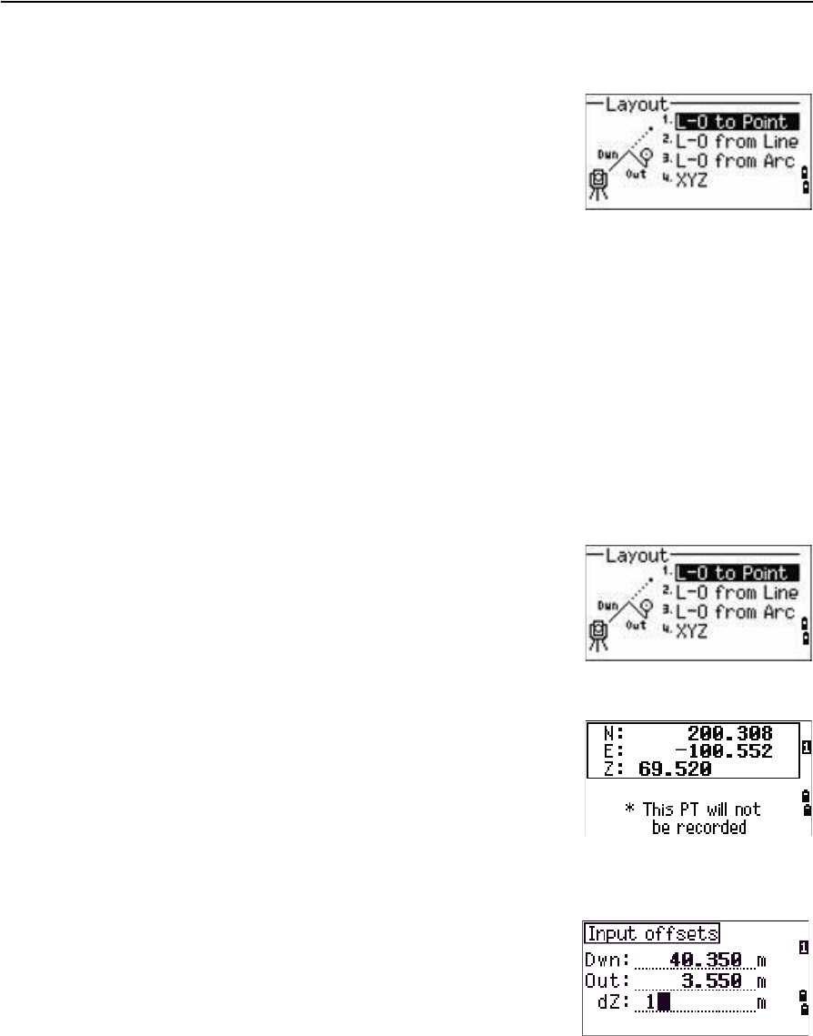
Layout menu
To access the Layout menu, press [L-O] in the BMS.
To select a command from the Layout menu, press the
corresponding number key. Alternatively, press [^] or [v]
to highlight the command and then press [ENT].
The last function used is highlighted.
There are four layout options:
•L-O to Point, page 62
•L-O from Line, page 63
•L-O from Arc, page 64
•XYZ, page 65
L-O to Point
Use this method to lay out a point based on the down, out, and dZ location to a
specified line.
1. Press [1] or select L-O to Point from the
Layout menu.
2. Enter the first point (P1) along the line.
Alternatively, select the MSR softkey to measure a
point.
If you press [ENT] without entering a PT name, you
can enter temporary coordinates. Temporary
coordinates are not recorded in the job.
3. Enter the second point (P2) along the line.
4. Enter offsets to the line.
To enter the value 0.0000, press [ENT] in a blank field.
5. Rotate the instrument until the dHA is close to 0°00'00".
6. Sight the target, and then press [MSR1] or [MSR2].
Sta Distance from P1 along the line
O/S Distance perpendicular to the line
(+) Right side of the P1−P2 line
(-) Left side of the P1−P2 line
dZ Difference in height from the line
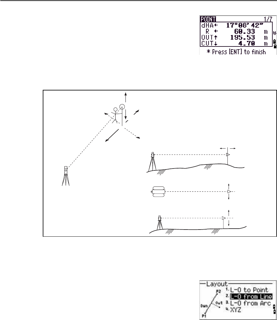
Trimble TS635 Construction Total Station User Guide 63
Applications 4
When a distance measurement is taken, the
difference between the measured point and the
design point appears.
7. To record the point as an SO record, press [ENT].
Note – Press [DSP] to switch between display screens. See
also page 83.
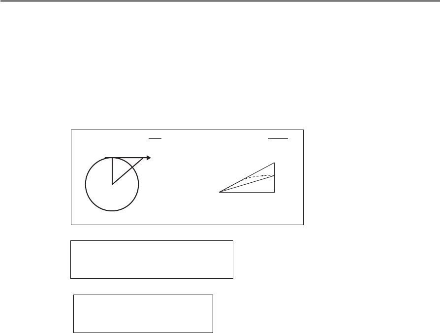
The following figure shows the terminology used to guide you to the required point.
L-O from Line
Select this option to measure distance and offset values along a specified line.
1. Press [2] or select L-O from Line from the
Layout menu.
2. Enter the first point for the reference line.
Alternatively, select the MSR softkey to measure a
point.
If you press [ESC] in the Record PT screen, the
measured point is used but not recorded in the
job.
3. Enter the second point for the reference line.
4. Enter an asterisk ( for example, A*) in the PT field to perform a wildcard search.
A list of matching points appears. Highlight a point in the list and then press
[ENT].
Fill
Out
Cut
L
R
In In Out
R
L
Fill
Cut
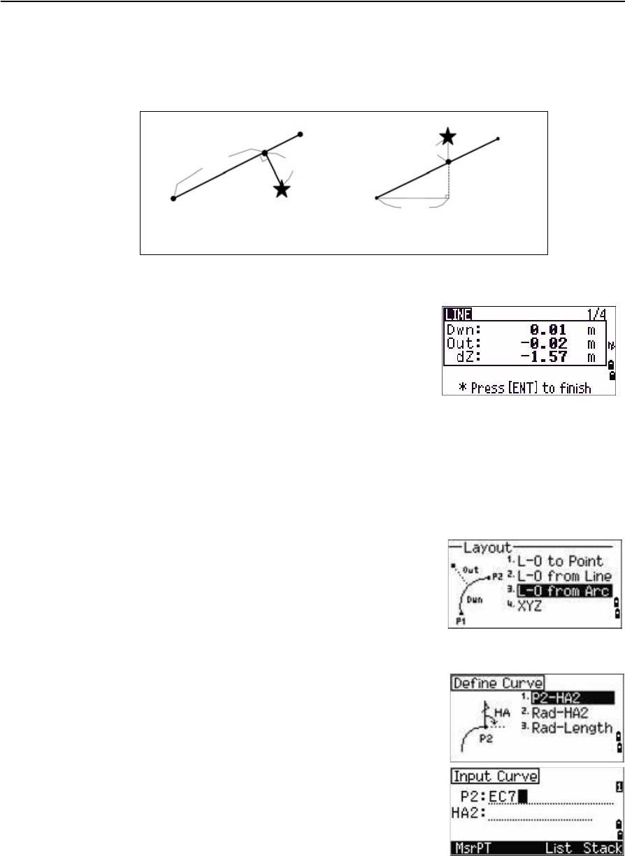
4 Applications
64 Trimble TS635 Construction Total Station User Guide
The following figure shows how to determine or input a location relative to a
line used for Layout.
5. Sight the prism or reflective sheet and press [MSR1] or [MSR2].
Note – Press [DSP] to switch between display screens. See also page 83.
L-O from Arc
Select this option to measure distance and offset values on the arc-curve.
1. Press [3] or select L-O from Arc from the
Layout menu.
2. Enter the start of the curve point (P1) and the
azimuth of its tangent line (HA1).
Alternatively, to enter P1 by direct measurement,
select the MSR softkey.
3. Choose a method to define the curve.
P2 can be any point on the tangent line that is to
exit the curve.
4. In the radius (Rad) field, enter a positive value for
a clockwise curve. Enter a negative value for a
counter-clockwise curve.
Dwn Horizontal distance from P1 to the
measured point along the P1-P2 line 6.
Out Horizontal offset from the P1-P2 line to
the measured point
dZ Vertical offset from the P1-P2 line to
the measured point
Plain view Side view
PT1
PT2
Dwn Out
Prism
Prism PT2
Dwn
PT1
dZ
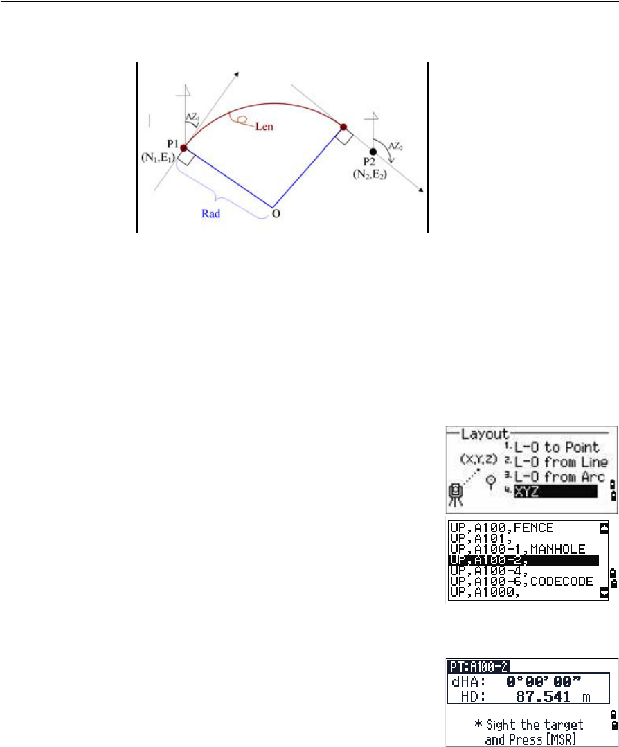
Trimble TS635 Construction Total Station User Guide 65
Applications 4
Once you entered all factors, the TS635 Construction Total Station calculates
the curve. If the curve length (Len) is too large for a circle of the given radius, the
curve is shortened.
Note – Press [DSP] to switch between display screens. See also page 83.
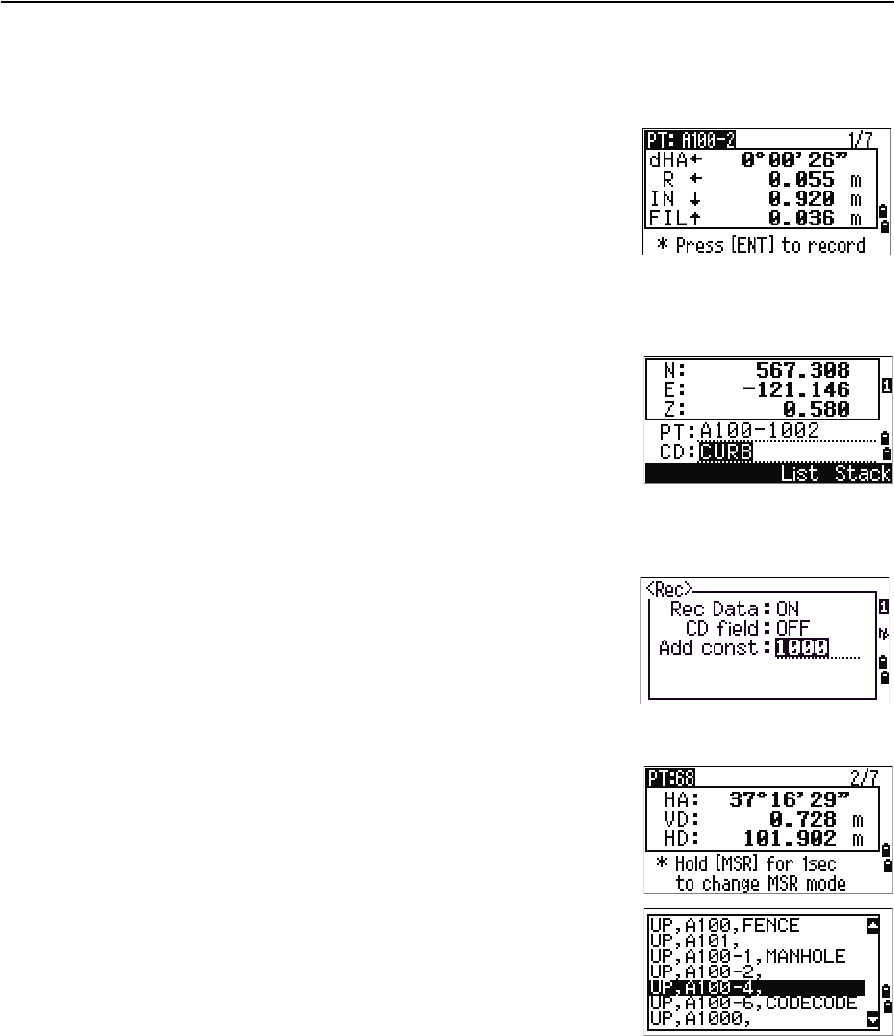
XYZ
Select this option to specify the layout point by coordinates.
1. Press [4] or select XYZ in the Layout menu.
2. Do one of the following:
–Enter the point name that you want to
establish and then press [ENT].
–Specify the point by code or radius from the
TS635 Construction Total Station. If several
points are found, they are displayed in a list.
Press [^] or [v] to move up and down the list.
Use [<] to move up one page, or [>] to move
down one page.
3. Highlight a point in the list and then press [ENT].
The delta angle and the distance to the target are
shown.
4. Rotate the instrument until the dHA is close to
0°00'00". Press [MSR1] or [MSR2].
dHA Difference in horizontal angle to
the target point
HD Distance to the target point
4 Applications
66 Trimble TS635 Construction Total Station User Guide
5. Ask the rod person to adjust the target position. When the target is on the
intended position, the displayed errors become 0.000 m (0.000 ft).
Once a measurement is taken, the Cut/Fill value and Z coordinate are updated
as the VA is changed.
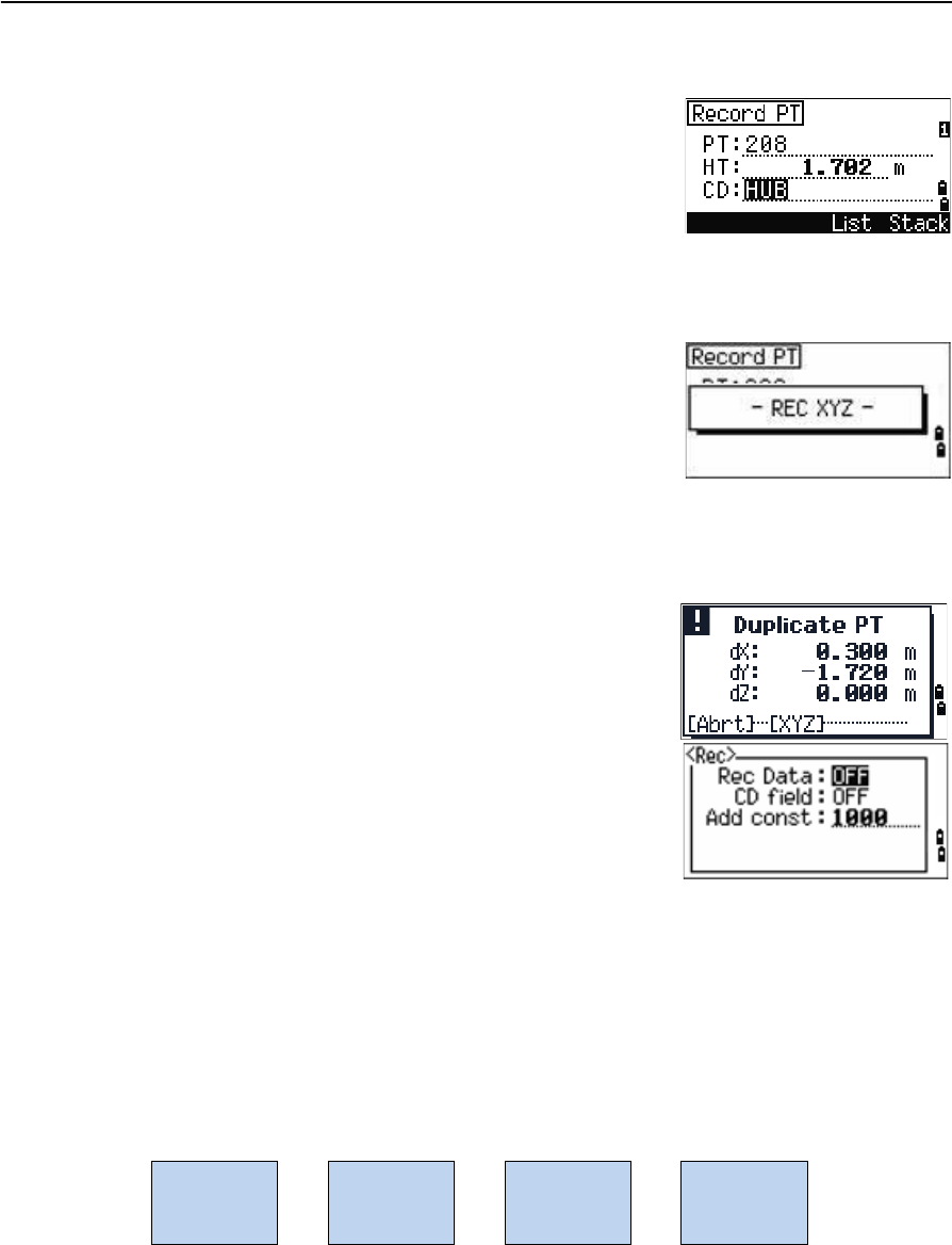
6. To record the point, press [ENT]. The PT field
defaults to the specified PT + 1000.
Press [MENU] and then select Settings / Rec.
Use the Add Constant field to specify an integer.
The integer is added to the point number that is
being laid out to generate a new number for
recording the layout point. The default value is
1000. For example, when you stake out PT3 with
an Add Constant of 1000, the default value in the
SO field (layout record) is 1003.
The display then returns to the observation
screen. Press [ESC]. The display returns to the
PT/CD/R input screen. If you entered the
stakeout point using a single point name, the PT
defaults to the last PT + 1.
7. If you selected a point from the list, the display
returns to the list, unless all points have been
selected. Press [ESC] to return to the point input
screen.
dHA Difference in horizontal angle to
the target point
R/L Right/Left (Lateral error)
IN/OUT In/Out (Longitudinal error)
CUT/FIL Cut/Fill
Trimble TS635 Construction Total Station User Guide 67
Applications 4
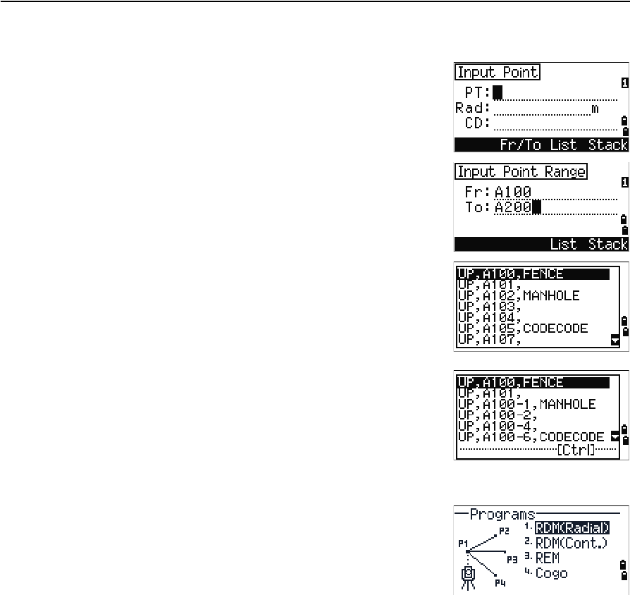
Advanced feature: Specifying a layout list by inputting points by range
1. Select the Fr/To softkey when the PT field is
selected.
2. Enter the start point (Fr) and the end point (To).
The range between Fr and To must be less than
1001 points.
–If existing points are found between Fr and
To, a point list appears.
To highlight a point in the list, press [^] or [v].
To go to the layout observation screen, press
[ENT].
–If you have assigned a control job, and
additional points are found in the control
job, the Ctrl softkey appears under the list.
Programs menu
To access the Programs menu, press [PRG] in the BMS.
To select a command from the Programs menu, press
the corresponding number key. Alternatively, press [^] or
[v] to highlight the command and then press [ENT].
The last function used is highlighted.
The Programs menu has the following options:
•RDM (Radial), page 69
•RDM (Cont), page 69
•REM, page 70
•V-Plane, page 70
•Cogo, page 71
4 Applications
68 Trimble TS635 Construction Total Station User Guide
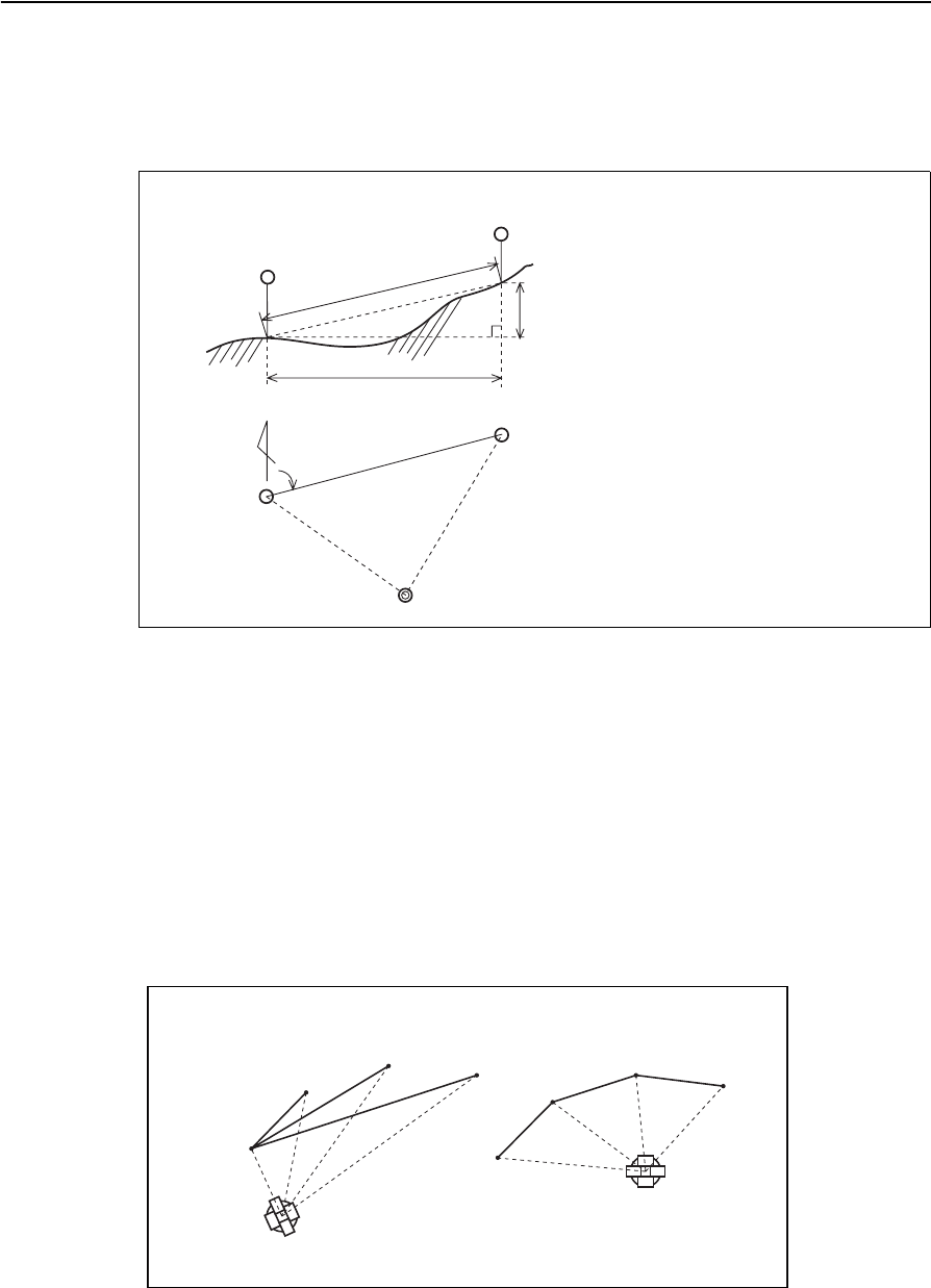
Remote distance measurement (RDM) - overview
RDM or “Remote distance measurement” measures the horizontal distance, vertical
distance, and slope distance between two points.
Difference between RDM (Radial) and RDM (Cont) measurement methods
RDM (Radial) calculations are made with reference to the first point. RDM (Cont)
calculations are made with reference to the two preceding points.
rSD Slope distance between two points
rVD Vertical distance between two points
rHD Horizontal distance between two points
rV% Percentage of grade (rVD/rHD) × 100%
rGD Vertical grade (rHD/rVD):1
rAZ Azimuth from first point to second point
Second sighting point
rVD
Second sighting point
Station point
First sighting
First sighting
Horizontal angle 0 direction
rHA
rSD
rHD
point
point
RDM(Radial) RDM(Cont)
P1
P2
P3 P4
P1
P2
P3 P4
Trimble TS635 Construction Total Station User Guide 69
Applications 4
RDM (Radial)
Choose this option to measure between the current point and the first point measured.
1. Press [1] or select RDM(Radial) in the
Programs menu.
2. Sight the first point and press [MSR1] or [MSR2].
The distance from the station point to the first
point appears.
3. Sight the second point and press [MSR1] or [MSR2].
The distances between the first and second point
are displayed.
4. To change display screens, press [DSP].
5. Press [ESC] to exit.
RDM (Cont)
Choose this option to measure between the current point and the immediately
preceding point.
1. Press [2] or select RDM(Cont.)from the
Programs menu.
2. Follow the procedure as for a radial RDM
measurement. See also RDM (Radial), page 69.
rSD Slope distance between two points
rVD Vertical distance between two
points
rHD Horizontal distance between two
points
rHA Azimuth from first point to second
point
rV% Percentage of grade (rVD/rHD) ×
100%
rGD Vertical grade (rHD/rVD): 1
4 Applications
70 Trimble TS635 Construction Total Station User Guide
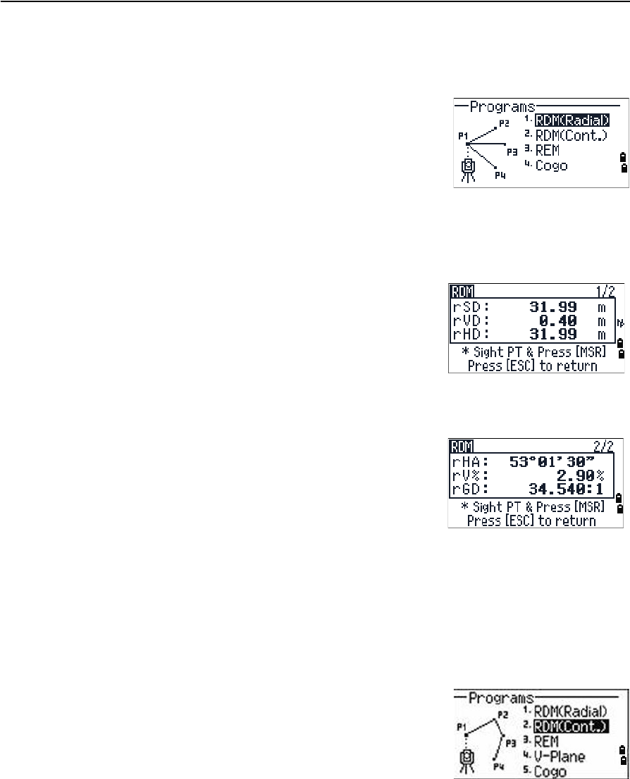
REM
Choose this option to measure a remote elevation.
Note – A prism is required only at the sighting (target) point.
1. Press [3] or select REM in the Programs menu.
2. Enter the height of the target.
3. Sight the target point and press [MSR1] or [MSR2].
4. Loosen the vertical clamp and then turn the
telescope to aim at an arbitrary point.
The difference in elevation (Vh) appears.
5. Press [ESC] to exit.
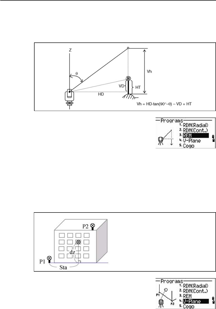
V-Plane
Choose this option to measure distance and offset values in the vertical plane, using
the 2-Pt Reference Plane function.
1. Press [4] or select V-Plane in the Programs
menu.
2. Enter the first point in the vertical plane:
Station point
Sighting point
Arbitrary point
Baseline
Trimble TS635 Construction Total Station User Guide 71
Applications 4
a. To enter the first point by direct
measurement, select the MSR softkey. A
temporary observation screen appears.
b. Press [MSR1] or [MSR2]. The Record PT screen
appears.
c. Enter a value in the PT and CD fields, and
then press [ENT].
3. Enter the second point in the vertical plane. To do this, repeat Step 2.
Once the plane is defined, the calculated Dwn and dZ values are updated as you
move the telescope. No distance measurement is required.
Note – Press [DSP] to switch between display screens. See also page 83.
4. Press [ESC] to exit this function.
Cogo
Choose the Cogo option to perform coordinate
geometry (Cogo) calculations.
To open the Cogo menu, press [5] on the Programs
menu.
There are five items in the Cogo menu:
•Inverse, page 72
•Input, page 74
•Area & Perm, page 76
•Down+Out, page 77
•Intersection, page 78
Dwn Horizontal distance from P1 to the
target point along the baseline
dZ Vertical distance from P1 to the
target point
4 Applications
72 Trimble TS635 Construction Total Station User Guide
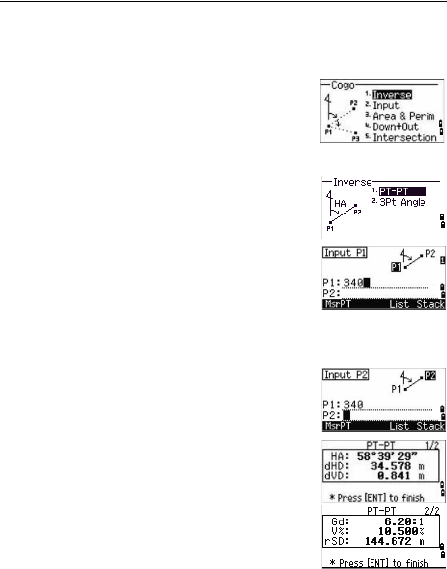
Inverse
Choose this option from the Cogo menu to calculate angle and distance between two
coordinates.
Press [1] or select Inverse in the Cogo menu. The
Inverse menu appears.
PT-PT inverse
PT-PT calculates the distance and the angle between
two input points.
To calculate a PT–PT inverse:
1. Press [1] or select PT-PT in the Inverse menu.
2. Enter the first point number or name, and then
press [ENT].
If you press [ENT] without entering a point name, a
coordinate input screen appears, and you can enter
coordinates. These coordinates are not stored to the
database. If you want to store the point, specify a new
point name.
3. Type the second point number/name, and then
press [ENT]. If necessary select the MSR softkey to
shoot the point on the spot so that you can use it
in the calculation.
The azimuth, horizontal distance, and vertical
distance from the first point to the second point
are displayed.
4. Do one of the following:
–To return to the PT input screen, press [ESC].
–To return to the Cogo menu, press [ENT].
–To change the contents of the result screen,
press [DSP].
Gd Grade (HD/VD)
V% 100/Gd
rSD Slope distance PT1 to PT2
Trimble TS635 Construction Total Station User Guide 73
Applications 4
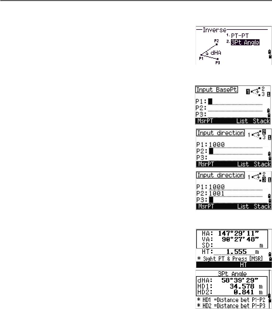
3Pt Angle
If you choose 3Pt Angle, the TS635 Construction Total
Station calculates the angle between two lines defined
by three points.
To calculate a 3Pt angle:
1. Press [2] or select 3Pt Angle from the Inverse
menu.
P1 is the base point. Two lines are to be defined
by P2 and P3, both from P1.
2. Enter the P1 point name. Alternatively, use the
MSR softkey to take a measurement to the point.
3. Enter the second point (P2) to define the
baseline, P1–P2. The angle (dHA) is measured
from the baseline.
4. Enter the third point (P3) to define the second
line, P1–P3.
When you press the MSR softkey, a temporary
measuring screen appears. Sight the target and
press [MSR1] or [MSR2] to take a measurement.
After the measurement, a recording point screen
appears. To store the measured point, enter the
PT, HT, and CD values and press [ENT]. To use the
point without recording it, press [ESC].
When you have entered three points, the
instrument calculates the angle and distances.
5. Do one of the following:
–To return to the Inverse menu, press [ENT].
–To return to the Input BasePt screen, press
[ESC].
4 Applications
74 Trimble TS635 Construction Total Station User Guide
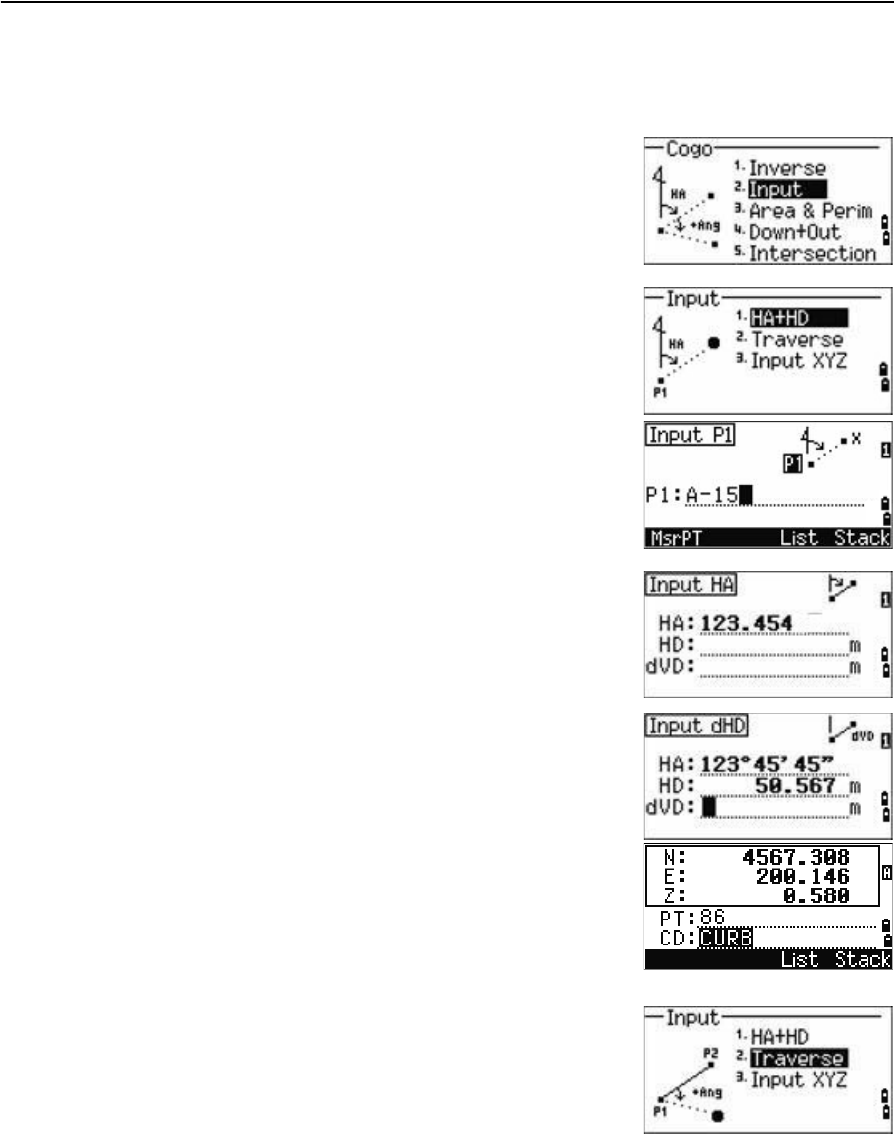
Input
Choose this option from the Cogo menu to calculate and manually input coordinates.
To enter the Input menu, press [2] or select Input from
the Cogo menu. There are three functions in this menu
for recording new coordinate points.
Azimuth+HD input
To calculate a coordinate by an angle and distance
input from the base point (P1), press [1] or select HA+HD
from the Input menu.
Enter the base point, P1. Type the point name and press
[ENT].
Enter the azimuth, horizontal distance, and vertical
distance. Then press [ENT].
For example, to enter 123°45'45", type 123.4545 and then
press [ENT].
If you do not enter a value in the dVD field, the value
0.0000 is used.
A recording point screen with the calculated
coordinates appears. The PT field defaults to the last
recorded point + 1.
Press [ENT] to store the point.
Traverse
To calculate a new point based on two defined points
and the angle, horizontal and vertical distances from
the line defined by those two points, use the Traverse
(2Pt Angle) function.
Press [2] or select Traverse in the Input menu.
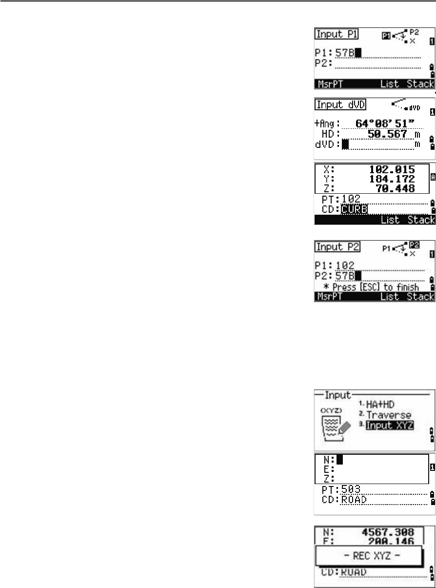
Trimble TS635 Construction Total Station User Guide 75
Applications 4
To enter P1 and P2, enter point names or take
measurements to targets.
Enter the plus-minus angle, horizontal distance, and
vertical distance from the baseline defined by P1–P2.
If you do not enter a value in the dVD field, the value
0.0000 is used.
When you press [ENT] in the dVD field, a new point is
calculated. The name in the PT field defaults to the last
recorded point, + 1.
To record the new point and return to the point input
screen, press [ENT].
P1 (the base point) defaults to the previously recorded
point value. P2 defaults to the previous P1 value.
BTip – To continuously calculate a new point, enter +Ang, HD, and dVD from the previous
bearing line. This is a convenient way to enter Traverse points.
Entering coordinates
To manually enter the XYZ coordinates, press [3] or
select Input XYZ from the Input menu.
The PT name defaults to the last recorded PT + 1.
Enter the coordinates using the numeric keys. To move
to the next field, press [ENT] or [v] in a field.
To store the point as an MP record and return to the
point input screen, press [ENT] in the Z field. The default
PT is incremented to the next value.
You can record NE, NEZ, or Z-only data.
4 Applications
76 Trimble TS635 Construction Total Station User Guide
Area & Perm
Choose this option from the Cogo menu to calculate area and perimeter.
Press [3] or select Area & Perim in the Cogo menu.
To take a measurement, enter the first point and press
[ENT], or select the MSR softkey.
In the upper right corner of the screen, a counter
indicates how many points you have entered.
To input point numbers consecutively, use the Fr/To
softkey. See also Advanced feature: Entering a range of
points, page 76.
If you enter a new point name, you can enter new
coordinates and record the point. If you do not want to
record the point, press [ENT] without entering a value in
the PT field. An XY coordinate input screen appears.
Continue to enter points until you have defined all the
points in the lot. Then, press [v] to calculate the area and
perimeter.
The first and last points that you enter are joined to
close the area. You must enter the points in the order in
which they define the lot. You can enter up to 99 points.
Press [ENT] to exit from the function, or press [ESC] to
return to the previous screens one by one.
Advanced feature: Entering a range of points
To quickly enter a sequential range of points, use the
range input function. To access this function, select the
Fr/To softkey in the No. 01 or No. 02 input screens.
Enter the start point name in the Fr field and the end
point name in the To field. You can include letters and
hyphens in the point names, but the last character must
be numeric.
Trimble TS635 Construction Total Station User Guide 77
Applications 4
To start searching for matching points, press [ENT] in the
To field. The counter shows the number of matching
points found.
When the search is complete, you are returned to the
Input PT screen.
Select the Calc softkey to calculate the area and
perimeter, or enter point names in the PT field.
Press [ESC] to return to the Input PT screen where the
preceding point name appears.
Note – If you search for a point when a control job is specified, and the system cannot find
the point in the current job, the control job is also searched. If the point is found in the
control job, it is copied to the current job as a UP record. See also Setting the control job,
page 89.
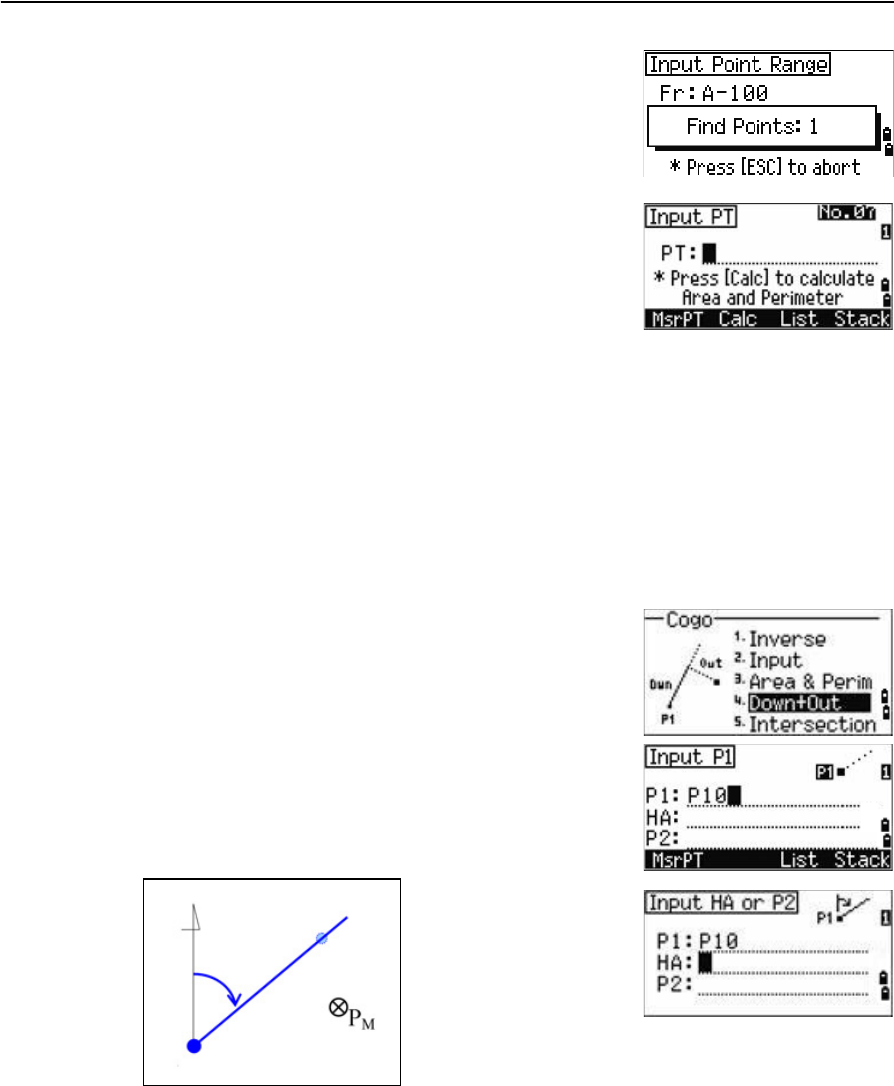
Down+Out
Choose this option from the Cogo menu to calculate coordinates from Down and Out.
Press [4] or select Down & Out in the Cogo menu.
Enter the base point (P1).
Specify the azimuth bearing. To do this, enter a value in
the HA or P2 field. P2 is a second point on the line.
Enter the horizontal distance along the baseline (Dwn), the horizontal distance
perpendicular to the line (Out), and the vertical distance (dVD).
HA
P2
P1
4 Applications
78 Trimble TS635 Construction Total Station User Guide
A negative value in the Dwn field means the opposite direction along the defined
bearing line.
A negative value in the Out field is for the left-hand side of the bearing line.
To calculate the coordinates of the point (PM), press
[ENT] in the dVD field. You can change the Z coordinate
here.
To record the point, press [ENT] in the CD field.
The coordinates are stored as a CC record.
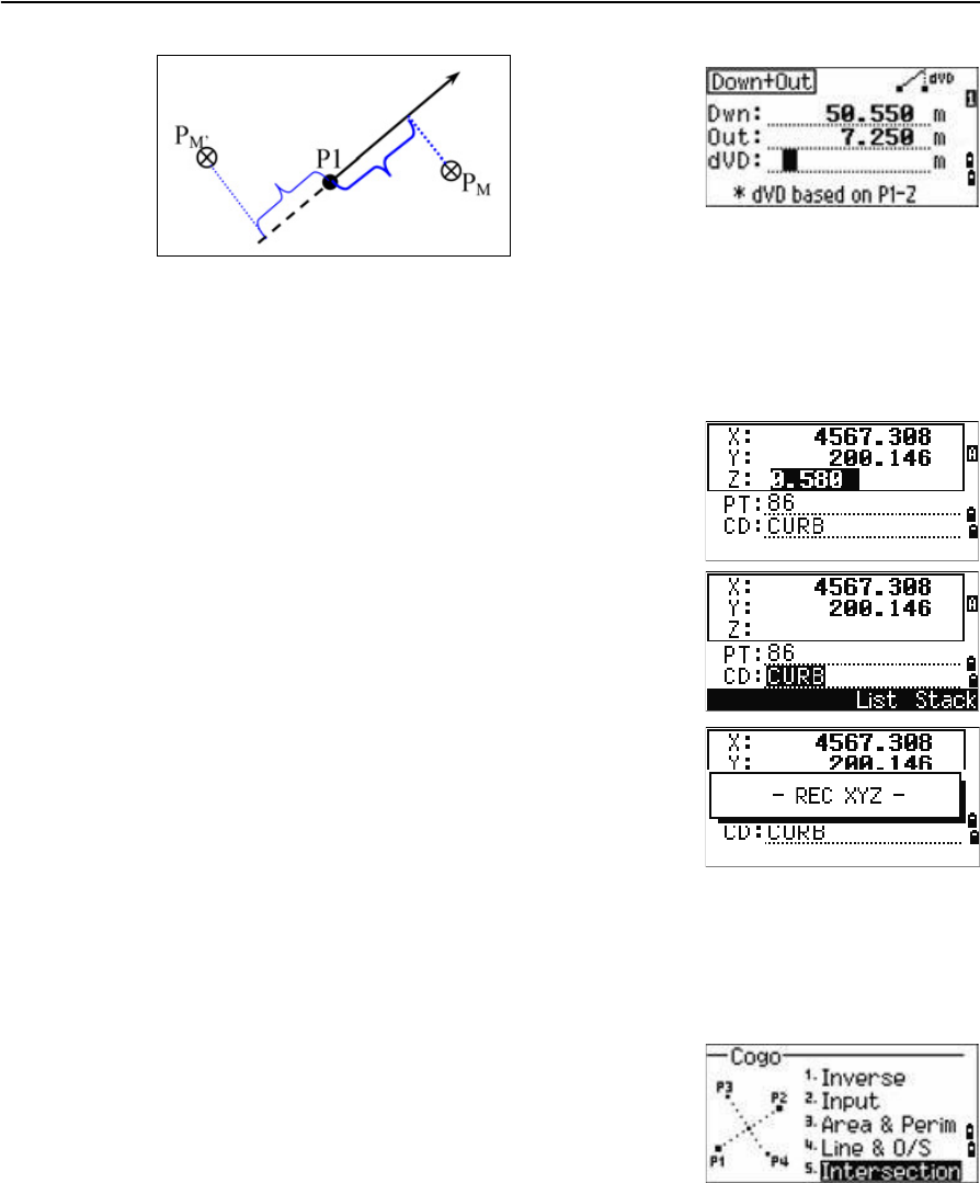
Intersection
Choose this option from the Cogo menu to calculate coordinates using intersection
functions.
Press [5] or select Intersection in the Cogo menu.
The Intersection menu appears. It has four functions for
calculating coordinates.
Out(-)
Dwn(-)
Out(+)
Dwn(+)
Trimble TS635 Construction Total Station User Guide 79
Applications 4
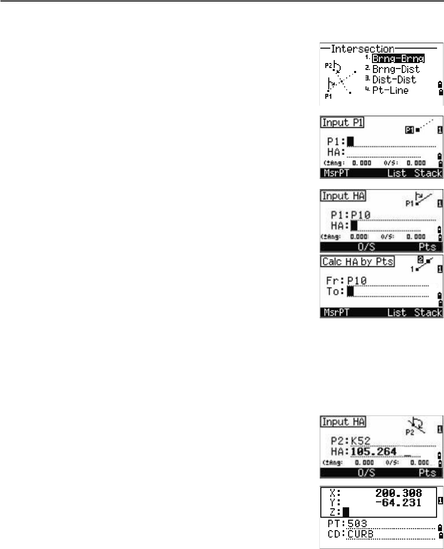
Calculating a bearing-bearing intersection
A bearing-bearing intersection is the intersection point
of two lines. To calculate a bearing-bearing intersection:
1. Press [1] or select Brng-Brng in the Intersection
menu.
2. Enter the first point name and press [ENT].
Alternatively, to measure directly to the point,
select the MSR softkey.
3. Define the first line by azimuth.
4. To define the line by two points, select the Pts
softkey. The Fr field defaults to the P1 point, but
you can change the selected point. In the To field,
enter or measure to the second point.
See also Advanced feature: Entering angle and
distance offsets, page 82.
5. Do one of the following:
–To return to the previous screen, press [ENT]. The calculated value appears in
the HA field.
–To go to the next screen, press [ENT].
6. Define the second line by two points or by P2 and
HA.
7. To calculate the coordinates of the intersection
point, press [ENT] in the HA field.
The calculated coordinates are displayed. You
can input a Z coordinate if necessary.
8. Enter a value in the PT field and in the CD field.
9. To record the point, press [ENT].
4 Applications
80 Trimble TS635 Construction Total Station User Guide
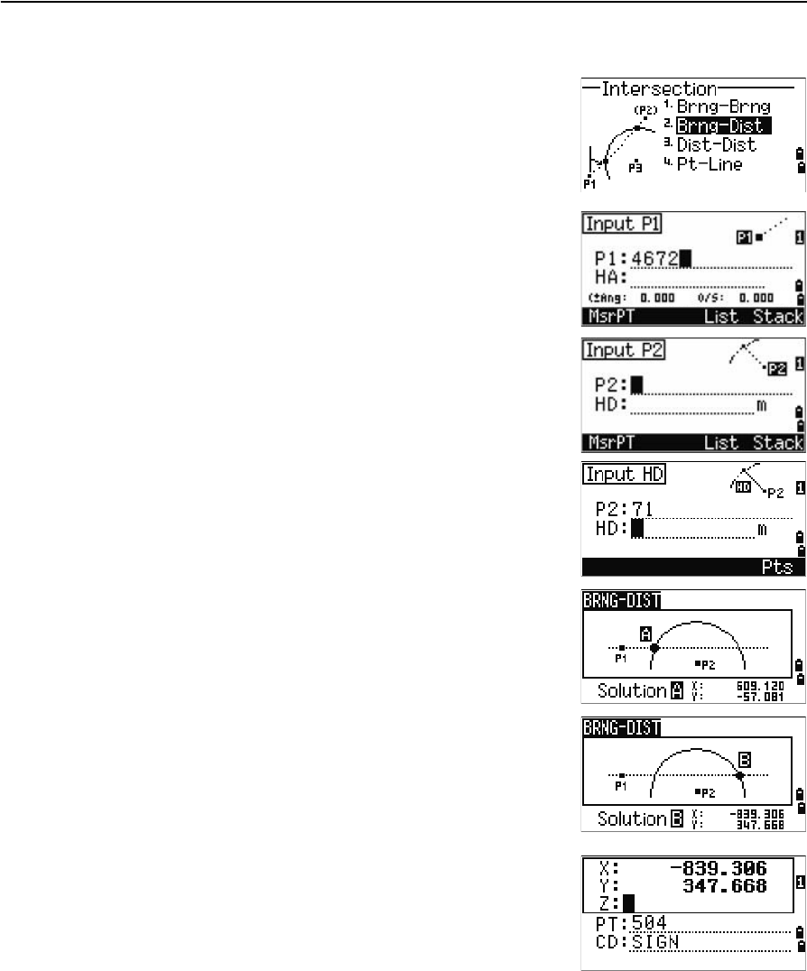
Calculating a bearing-distance intersection
1. Press [2] or select Brng-Dist in the Intersection
menu.
Brng-Dist calculates the intersection point
formed by one line and one distance (radius).
2. Enter a point on the line.
The line can be defined by two points or by a
point and an azimuth.
3. Enter the second point (P2) as the center of the
circle.
4. Enter the distance from P2:
–To define the distance (HD) by two points,
select the Pts softkey.
–To calculate the coordinates of the
intersection point, press [ENT] in the HD field.
5. If there are two results, the first solution appears
graphically relative to the P1–P2 line. To display
the second solution, press [<] or [>].
6. To record the point, press [ENT] when the required
solution appears.
7. Enter a Z coordinate if necessary.
8. To move to the PT and CD fields, press [ENT].
Trimble TS635 Construction Total Station User Guide 81
Applications 4
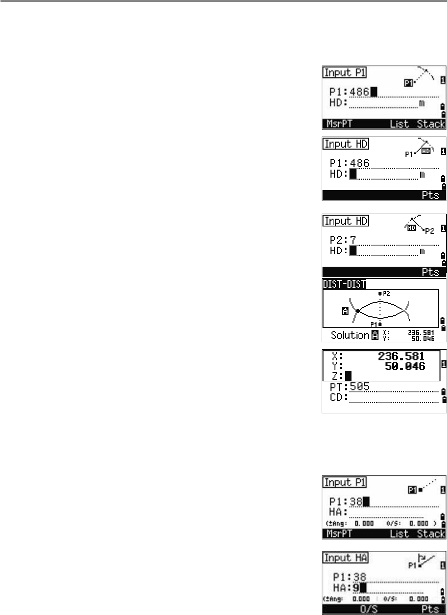
Calculating a distance-distance intersection
1. Press [3] or select Dist-Dist in the Intersection menu.
2. Enter the first point name and press [ENT], or
select the MSR softkey to measure directly to the
point.
3. Enter the distance from P1 and press [ENT].
4. To define the distance (HD) by two points, select
the Pts softkey.
5. Enter P2 and the distance from P2 (HD).
6. To calculate the coordinates of the intersection
point, press [ENT] in the HD field.
7. Press [<] or [>] to display the second solution.
8. To record the point, press [ENT] when the required
solution appears.
9. Enter a Z coordinate if necessary.
10. Press [ENT] to move to the PT and CD fields.
Calculating a point-line intersection
1. Press [4] or select Pt-Line in the Intersection menu.
2. Enter the first point name and press [ENT], or
select the MSR softkey to measure directly to the
point.
3. Enter the azimuth, or select the Pts softkey to
enter another point name on the line.
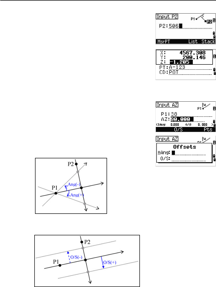
4 Applications
82 Trimble TS635 Construction Total Station User Guide
4. Enter the perpendicular point to the line, or
select the MSR softkey to take a measurement to
the point.
5. To calculate the coordinates of the intersection
point, press [ENT].
If P1 and P2 are 3D points, the Z coordinate of the
perpendicular point is calculated relative to the
P1–P2 slope.
6. Enter PT and CD then press [ENT] to record the
point.
Advanced feature: Entering angle and distance offsets
To display the offset input screen, select the O/S
softkey.
In the Ang field, enter a positive value to rotate the line
clockwise. Enter a negative value to rotate the line
counter clockwise.
In the O/S field, enter a positive value to specify an offset to the right. Enter a negative
value to specify an offset to the left.
Trimble TS635 Construction Total Station User Guide 83
Applications 4
Recording measurement data
To record points from any observation screen, press
[ENT].
PT defaults to the last recorded PT, + 1.
You can enter the PT name from the point list or the
point stack. See Entering a point from the point list,
page 49, and Entering a point from the point stack,
page 49.
To record the point, press [ENT] on the last field.
If HA or VA is moved after you take a measurement, but before you press [ENT], the
recalculated coordinates will be stored.
If the point name that you want to record already exists
in the job, an error message appears. Depending on the
type of existing record, you can overwrite the old record
with the new data. See Recording data, page 125.
If you do not need to record data, press [MENU] and set
Settings / Rec to OFF.
The default setting is OFF.
Switching between display screens
Press [DSP] to switch between display screens. See the [DSP] button, page 40. Each time
you press [DSP], the next screen appears. When you press [DSP] in the final screen, the
first screen appears.
The following line display screens are available.
LINE1 LINE2 LINE3 LINE4
dOWN
OUT
dZ
X
Y
Z
HA
VA
SD
HA
VD
HD
4 Applications
84 Trimble TS635 Construction Total Station User Guide
The LINE5 screen is available only if the secondary distance unit is set. See also Other
settings, page 94.
The following arc display screens are available.
The ARC5 screen is available only if the secondary distance unit is set. See also Other
settings, page 94.
The following plane display screens are available.
LINE5
HD
VD
SD
ARC1 ARC2 ARC3 ARC4
DWN
OUT
dZ
X
Y
Z
HA
VA
SD
HA
VD
HD
ARC5
HD
VD
SD
PLN1 PLN2 PLN3
DWN
dZ
X
Y
Z
HA
VA

CHAPTER
5
Trimble TS635 Construction Total Station User Guide 85
Menu Screen 5
In this chapter:
QJob
QSettings (basic job settings)
QData
QCommunication
Q1sec-Key
QCalibration
QTime
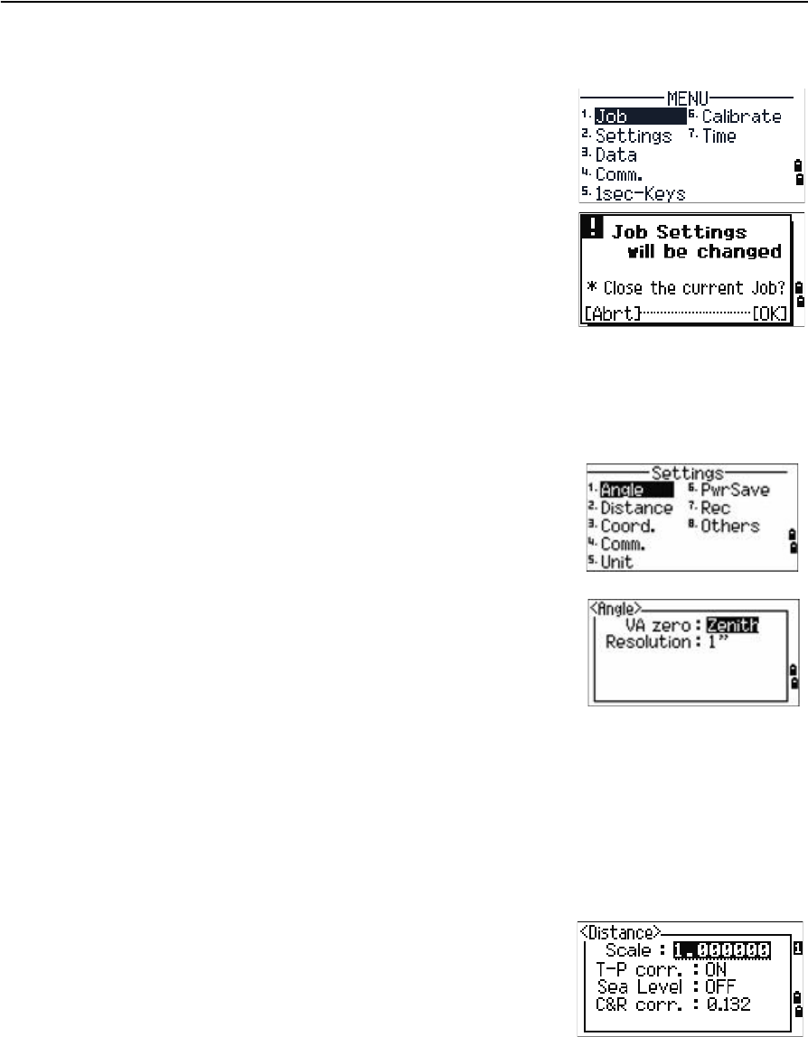
Use the MENU screen to access functions and
settings.
To display the MENU screen, press the [MENU] key.
5 Menu Screen
86 Trimble TS635 Construction Total Station User Guide
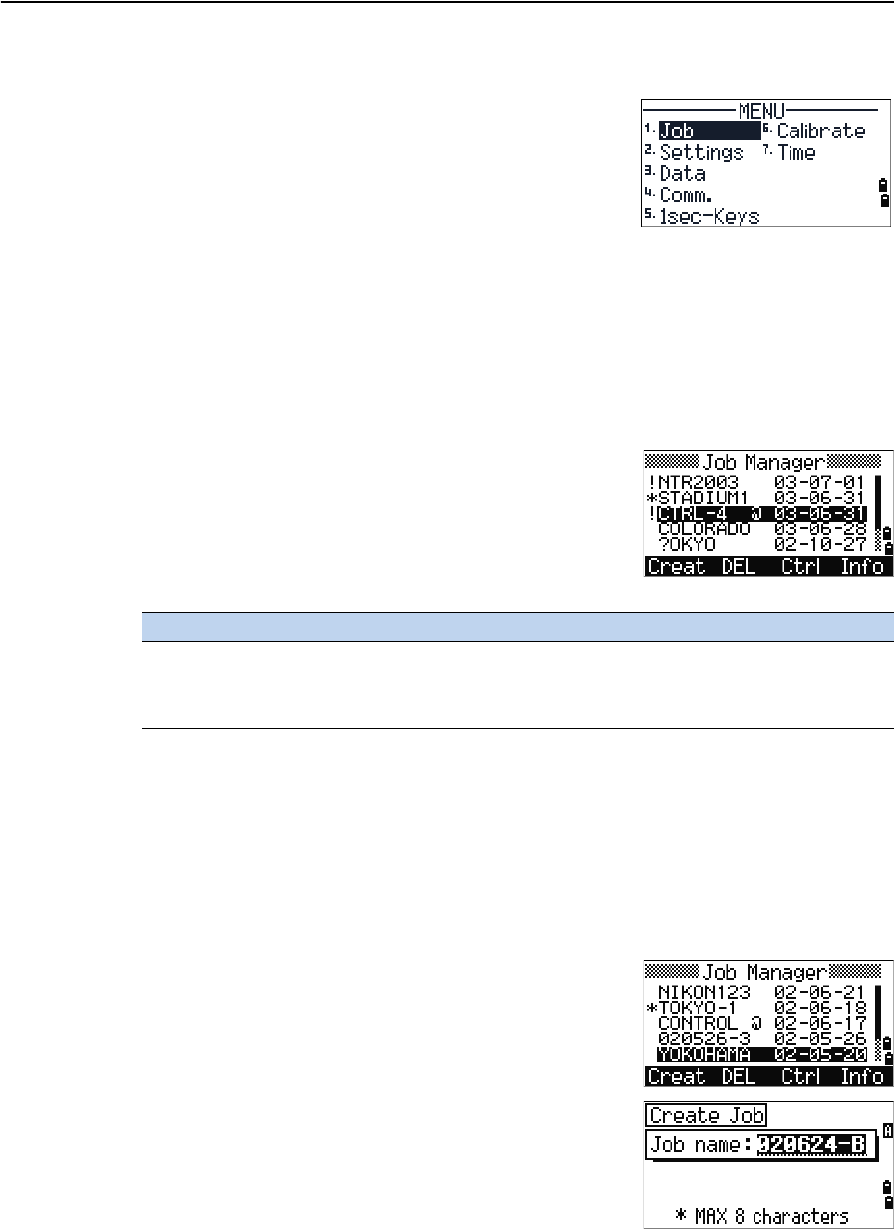
Job
Use the Job option to open, create, delete, and manage
jobs.
To open the Job Manager, press [1] or select Job from
the MENU screen.
If jobs are stored on the TS635 construction total
station, the job list appears. It shows all the stored jobs
with the newest job at the top of the list. See Opening
an existing job, page 86.
If no jobs are stored, the Create Job screen appears. See Creating a new job, page 86.
Opening an existing job
The job list shows all the jobs stored on the instrument,
in descending date order.
The following symbols provide extra information about
jobs:
Press [^] to move up or [v] to move down the job list. Press [ENT] to open the highlighted
job.
When you open a job, all job settings are automatically changed to match those used in
the open job.
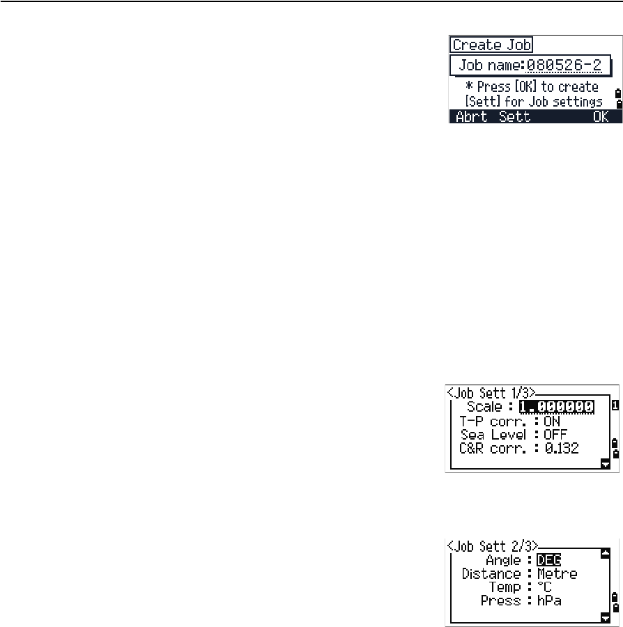
Creating a new job
1. Select the Creat softkey in the job list.
2. Enter a job name of up to eight characters. Select
[ENT].
3. Do one of the following:
Symbol Meaning
* Current job
@ Control job
! Some of the job settings are different from the current job
Trimble TS635 Construction Total Station User Guide 87
Menu Screen 5
–To check the job settings, select the Sett
softkey.
–To create a new job using the current job
settings, press [ENT] or select the OK softkey.
Job settings
Job settings are separate from other temporary settings.
Job settings are established when a job is created, and cannot be changed. This ensures
that the data in a job is correctly stored in the database, and that all necessary
corrections are applied when you store each record.
To move between fields, press [^] or [v]. Alternatively, to move to the next field, press [ENT].
To change the setting in the selected field, press [<] or [>].
To confirm the job settings and create the job, press [ENT] in the last field.
Screen 1
Screen 2
Scale Factor 0.999600 to 1.000400
T-P correction ON / OFF
Sea Level ON / OFF
C&R correction OFF / 0.132 / 0.200
Angle unit DEG / GON /MIL
Distance unit Metre / US-Ft / I-Ft
Temp unit °C / °F
Press unit hPa / mmHg / inHg
5 Menu Screen
88 Trimble TS635 Construction Total Station User Guide
Screen 3
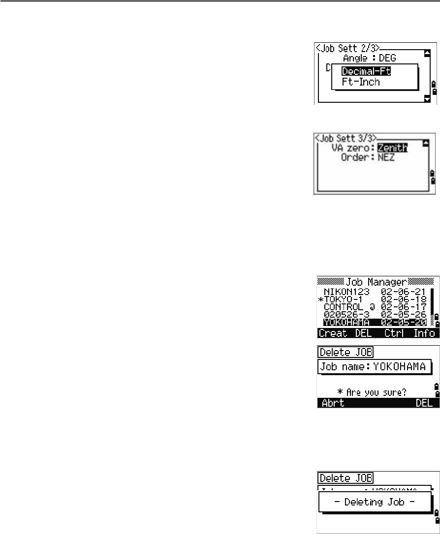
If you select US–Ft or I–Ft, an additional settings
screen appears. Use this screen to specify whether to
display values in Decimal–Ft or Ft–Inch.
Deleting a job
Note – There is no undelete function in Job Manager. Before you press [ENT] or select DEL,
make sure that the selected job is the one that you want to delete.
1. In the job list, highlight the job to delete.
2. Select the DEL softkey. A confirmation screen
appears.
3. Do one of the following:
–To delete the selected job, press [ENT] or
select the DEL softkey.
–To cancel the deletion and return to the
previous screen, press [ESC] or select the
Abrt softkey.
After you delete a job, the job list appears.
VA zero Zenith / Horizon
Order NEZ / ENZ
Trimble TS635 Construction Total Station User Guide 89
Menu Screen 5
Setting the control job
A control job has the same format as a standard job. You can open and modify it like
any other job, and you can use it to record any measured data.
To set the control job:
1. Highlight the job that you want to use as the
control job.
2. Select the Ctrl softkey.
A confirmation screen appears.
3. Do one of the following:
–To set the selected job as the control job,
press [ENT] or select the Yes softkey.
–To cancel the process, press [ESC] or select
the No softkey.
If a control job is already assigned, the newly
assigned control job replaces it as the control job.
To clear the selected control job, highlight the
current control job in the job list and select the
Ctrl softkey. Then press [ENT] or select the Yes
softkey.
Displaying job information
To display job information, highlight the job name and
then select the Info softkey.
The Information screen shows the number of records in
the job, the free space, and the date when the job was
created. Free space indicates how many points can be
stored in the job.
To return to the job list, press any button.
5 Menu Screen
90 Trimble TS635 Construction Total Station User Guide
Settings (basic job settings)
Use the Settings menu to configure the basic job
settings.
Press [2] or select Settings on the MENU screen.
Some job settings, as identified in the following
sections, cannot be changed once a job is created. If
you attempt to change any of these settings while a job
is open, a confirmation screen appears, asking you to
create a new job with the new settings, or to work with
the new settings without recording any data. See
Settings, page 126.
Angle
To change the angles, press [1] or select Angle in the
Settings menu.
The VA zero job setting cannot be changed once a job is created.
Distance
These settings cannot be changed once a job is created.
To change the distance, press [2] or select Distance in the Settings menu.
VA zero Zenith / Horizon
Resolution 1" / 5" / 10"
0.2/ 1/ 2mgon
0.005 / 0.02 / 0.05 mil
Scale Numeric value between 0.999600 and
1.000400
T-P corr ON / OFF
Sea Level ON / OFF
C&R corr OFF / 0.132 / 0.200
Trimble TS635 Construction Total Station User Guide 91
Menu Screen 5
Temperature and pressure corrections
Sea-level corrections
SD Slope dist. (before adj.)
SD' Slope dist. (after adj.)
K Compensation coefficient
P Pressure (hPa)
T Temperature (°C)
HD Horizontal dist. (before adj.)
HD' Horizontal dist. (after adj.)
ZSTN Instrument-Z
Re6370 km
K 275
106 P 10000.0
13.5951 980.665
×
---------------------------------------------
©¹
§·
××
273 T
+
---------------------------------------------------------------------------
–=
SD' 1 K
1000000
---------------------
+
©¹
§·
SD
×
=
HD' HD Re
×
ReZSTN
+
------------------------=
5 Menu Screen
92 Trimble TS635 Construction Total Station User Guide
Curvature and refraction corrections
Because the surface of the earth is curved, the vertical difference (VD and Z) at the
measurement point, as referenced to the horizontal plane, inevitably includes some
error. This error is called curvature error. Also, because the density of the air
surrounding the earth decreases with altitude, light is refracted at different rates at
different altitudes. The error caused by this change in refraction is called refraction
error.
HD Horizontal dist. (before adj.)
HD' Horizontal dist. (after adj.)
VD Vertical dist. (before adj.)
VD' Vertical dist. (after adj.)
SD Slope dist
VA Vertical angle
Re6370 km
k C&R constant (0.132 or 0.200)
Curvature error (A A')Refraction error (A A1')
PA'Horizontal
direction
A
OP
A1'
A1
A'
HD' HD SD22VA()sin
2Re
----------------------------------- 1k
2
---–
©¹
§·
–=
VD' VD HD2
2Re
-----------1k–()+=
Trimble TS635 Construction Total Station User Guide 93
Menu Screen 5
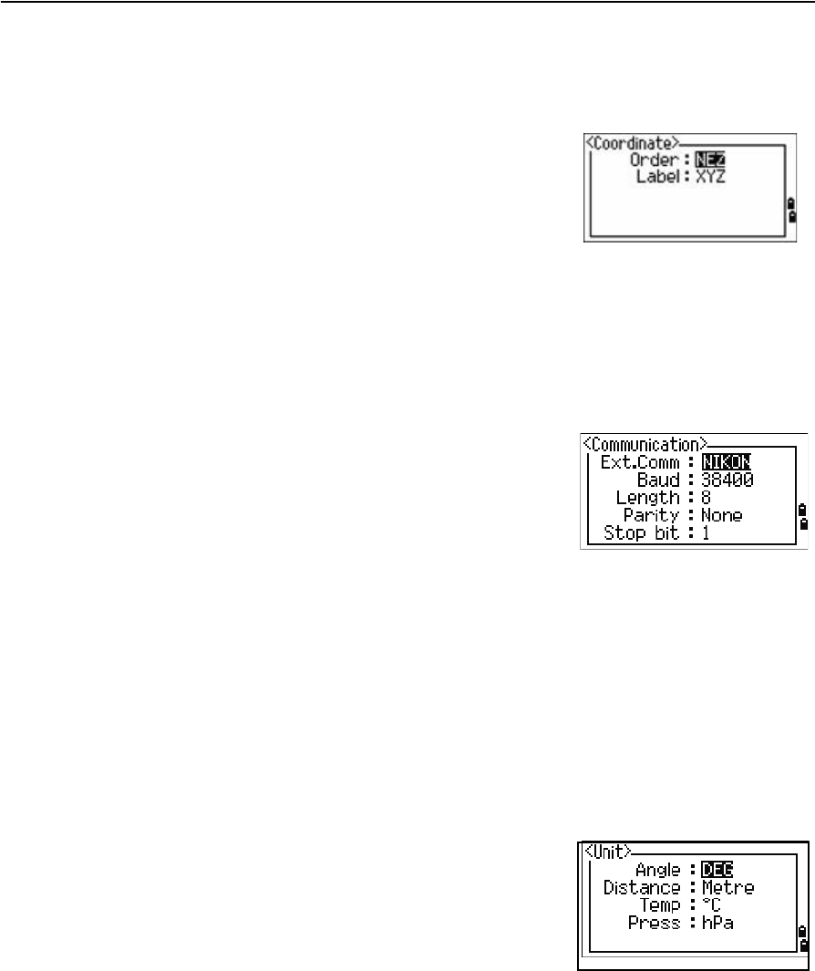
Coordinate
Press [3] or select Coord. in the Settings menu. The Coordinate menu appears.
The Order and AZ job settings cannot be changed once a job is created.
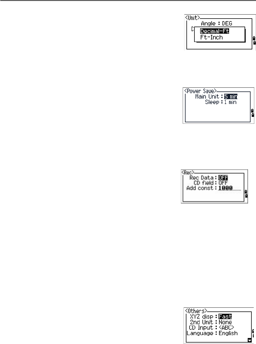
Communications
Press [4] or select Comm. in the Settings menu. The Communication menu appears.
See also Appendix B, Transferring Coordinate Data.
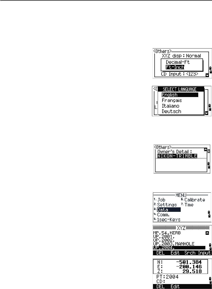
Unit
Note – The Angle, Distance, Temp, and Press job settings cannot be changed once a job is
created.
Press [5] or select Unit in the Settings menu. The Unit menu appears.
Order NEZ / ENZ
Label XYZ / YXZ / NEZ(ENZ)
Ext.Comm NIKON / SET
Port Serial/Bluetooth
Baud (bps) 1200 / 2400 / 4800 / 9600 / 19200 /
38400
Length 7 / 8
Parity EVEN / ODD / NONE
Stop bit 1 / 2
Angle DEG (Degree)
GON (GON)
MIL (Mil6400)
Distance Meter
US-Ft
I-F
Temp °C (Celsius)
°F (Fahrenheit)
Pressure hPa
mmHg
inHg
5 Menu Screen
94 Trimble TS635 Construction Total Station User Guide
If you select US-Ft or I-Ft, an additional settings screen
appears. Use this screen to specify whether to display
values in Decimal-Ft or Ft-Inch.
Power saving
To open the Power Save menu, press [4] or select PwrSave in the Settings menu.
Recording
Press [7] or select Rec in the Settings menu. The Rec Menu appears.
•If you need to record coordinate data from your observations, set the Rec Data
field to ON.
•If you would like to record a feature code when you record coordinate data, set
the CD field to ON. The CD field appears in the Recording PT screen.
•This field sets the default point number for the observed coordinate data when
you select Layout / XYZ.
Other settings
Press [8] or select Other in the Settings menu. The Others menu appears.
Main unit OFF / 5 min / 10 min / 30 min .
Sleep OFF / 1 min / 3 min / 5 min
Rec Data ON / OFF
CD field ON / OFF
Add const Integer between 1 and 999,999
XYZ disp Fast / Normal / Slow / +ENT
2nd Unit None / Meter / US-Ft / I-Ft
CD Input 123 / ABC
Language English / French / German / Italian /
Dutch
Owner’s Detail Up to 20 characters
Trimble TS635 Construction Total Station User Guide 95
Menu Screen 5
XYZ disp defines the speed to move to the next screen after showing XYZ of the input
point.
When the secondary unit is set to a unit, an extra display screen is available in the
BMS, layout observation screens, and L–O from line screens. The extra screen shows
the HD, VD, and SD in the secondary unit.
If you select US-Ft or I-Ft, an additional settings screen
appears. Use this screen to specify whether to display
values in Decimal-Ft or Ft-Inch.
The CD Input field sets the default input mode when a
CD field appears.
In the Language field, use [<] / [>] to open the language
screen and [v] / [^] to select the required language. Press
[ENT] to confirm. In the Reboot confirmation screen,
press [ENT] to restart the instrument. The instrument
reboots and shows the start-up screen in the selected
language. Then a regional setting screen appears, in
which you can quickly configure the instrument to a
pre-set combination of the default regional settings. See
Regional configuration, page 45.
The Owner’s Detail field allows you to enter your name
or the name of your company. If you enter a value in this
field, it appears when you start the TS635 construction
total station.
Data
Use the Data menu to view or edit records. To access it,
press [3] on the MENU screen.
Viewing coordinate data
Coordinate data appears in a list, with the newest
record at the bottom of the screen. Use [^] or [v] to scroll
through the records. Use [<] or [>] to move up or down
one page.
Press [ENT] to see more detailed information about the
selected record.
5 Menu Screen
96 Trimble TS635 Construction Total Station User Guide
The header (XYZ, YXZ, NEZ, or ENZ) depends on the Coord. Label setting, which is
accessed by pressing [MENU] and then selecting Settings / Coord. See also
Coordinate, page 93.
UP, MP, CC, SS, and SO records
All coordinate records contain PT, CD, X, Y, and Z fields.
•UP records are uploaded point coordinates.
•MP records are manually input point coordinates.
•CC records are points calculated in Cogo.
•SS records are sideshot records stored in the BMS.
•SO records are stored in layout functions.
Deleting coordinate records
1. In the XYZ screen, use [^] or [v] to highlight the
record that you want to delete. Then select the
DEL softkey.
2. A confirmation screen appears.
a. To delete the selected record, press [ENT] or
select the Yes softkey.
b. To cancel the deletion of data, press [ESC] or
select the No softkey.
Alternatively, delete coordinate data by selecting
the DEL softkey in the detailed display screen for
the record.
If the record that you want to delete is referred by
any station record, a confirmation message
appears.
Editing coordinate records
You can edit point, CD, and coordinate values in coordinate records. However, you
cannot edit the coordinate record for the current station.
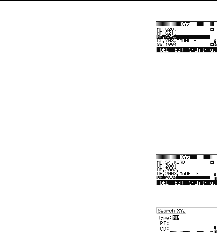
Trimble TS635 Construction Total Station User Guide 97
Menu Screen 5
1. Do one of the following:
–In the XYZ screen, use [^] or [v] to highlight
the record to edit. Then select the Edit
softkey.
–In the detailed data screen, select the Edit
softkey.
2. Use [^] or [v] to highlight a field. Then modify the value in the selected field.
3. When you have finished editing, press [ENT] in the CD field.
A confirmation screen appears.
4. Do one of the following:
–To accept the changes and return to the data view screen, press [ENT] or
select the Yes softkey.
–To go back to the edit screen, press [ESC] or select the No softkey.
Searching coordinate records
You can search for records by their type, point name, code, or by any combination of
these values.
In the XYZ screen, select the Srch softkey to access the
XYZ data search function.
To search for a record by point name, enter the point
name in the PT field and press [ENT] twice.
You can use the asterisk (*) as a wildcard. For example,
when you enter 500* in the PT field, the search matches the points named 500, 500-1,
500-A, and 5000.
To search for a record by point type, move to the Type
field and use [<] or [>] to change the selected point type.
The options are ALL, MP, UP, CC, and RE.
•If more than one point matches the search
criteria, the matching points are displayed in a
list.
Use [^] or [v] to highlight the required point. Press [ENT] to select it.
Detailed data for the selected record appears. Select the DSP softkey to change the
fields shown.
Press [ESC] to return to the list.
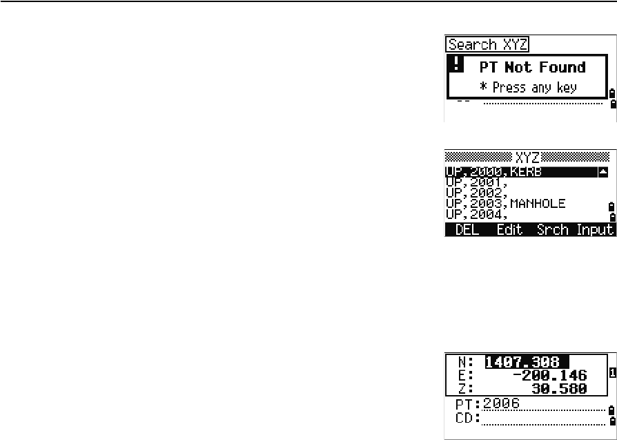
5 Menu Screen
98 Trimble TS635 Construction Total Station User Guide
•If no point matches the specified criteria, an
error screen appears. Press any button to return
to the data screen.
Entering coordinates
In the XYZ screen, select the Input softkey. A new
input point screen appears.
The PT field defaults to the last recorded PT + 1, but
you can change the value shown.
Enter the PT and CD and then press [ENT] to enter
coordinates.
Use the numeric keys to enter the coordinates. Press [ENT] or [v] in each field to move to
the next field.
When you press [ENT] in the CD field, the point is stored as an MP record.
After you have recording a point, the next point input
screen is shown with the updated default PT.
You can record NE, NEZ, or Z-only data.
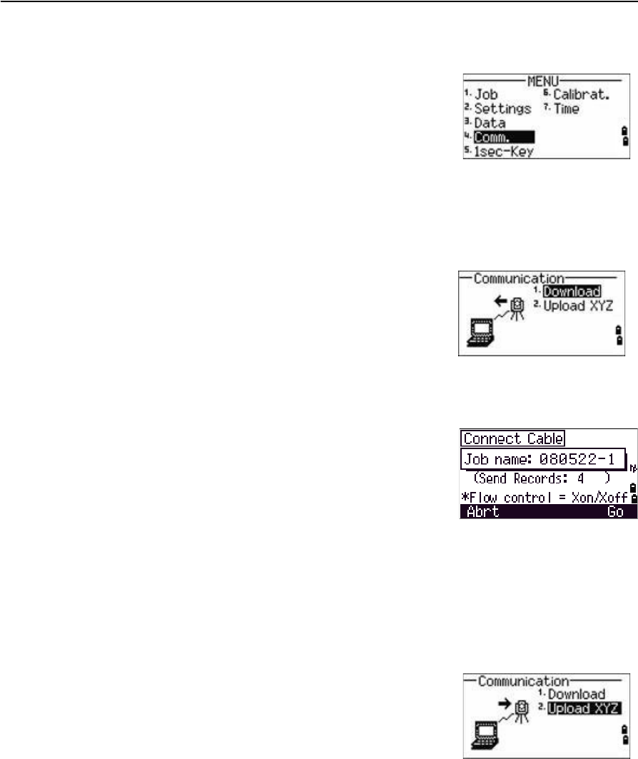
Trimble TS635 Construction Total Station User Guide 99
Menu Screen 5
Communication
Use the Communication menu to download or upload
data. To access it, press [4] or select Comm. on the
MENU screen.
Downloading coordinate data
To change the download settings, press [1] or select Download in the Communication
menu.
To display the total number of records that will be downloaded, press [ENT] in the Data
field.
As each record in the current job is output from the
TS635 construction total station, the current line
number is updated.
Once transferring is completed, you can choose
whether to delete the current job:
•To delete the current job, press [4].
•To return to the Basic Measurement Screen (BMS) without deleting the current
job, press [ESC] or select the Abrt softkey.
Uploading coordinate data
To upload coordinate data from a computer, press [2] or
select Upload XYZ in the Communication menu.
The default data format appears.
To change the order of data fields, select the Edit
softkey. See also Advanced feature: Editing the data
order for upload, page 100.
Otherwise, press [ENT].
Select the Job softkey to go to the Job Manager screen. See also Job, page 86.
Format NIKON (Fixed)
Data Coordinate (all)
Coordinate (layout records only)
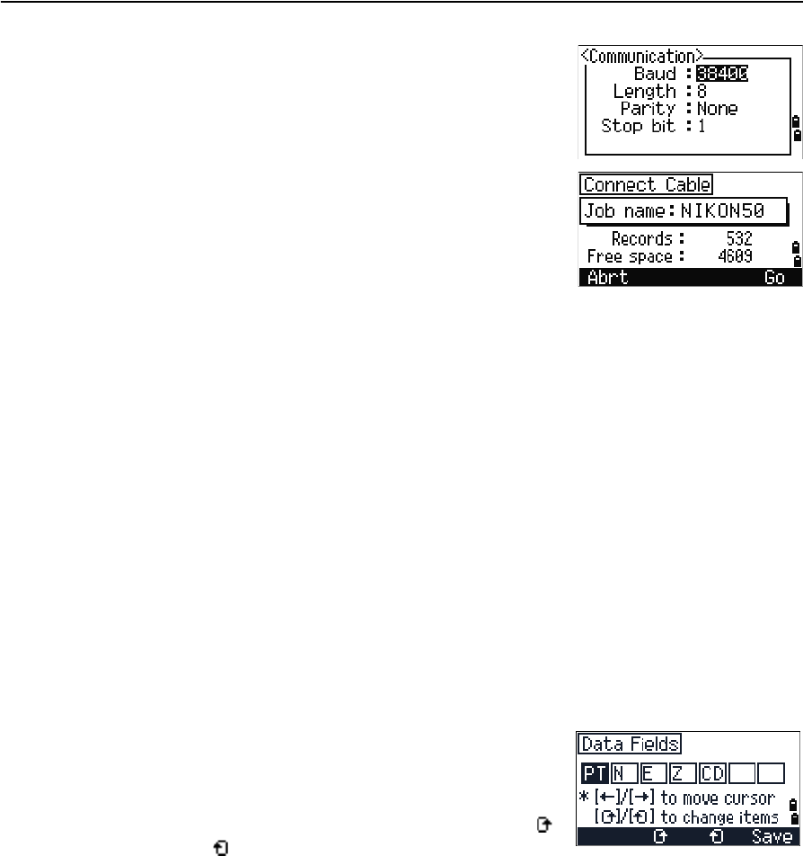
5 Menu Screen
100 Trimble TS635 Construction Total Station User Guide
To change the communication settings, select the Comm
softkey. The serial port settings must match the settings
used by the terminal software on the computer.
Use an RS-232C cable to connect the TS635
construction total station to the computer. In the
terminal program, set flow control to Xon/Xoff.
The Free space field shows the number of points that
can still be stored on the TS635 construction total
station.
Press [ENT] to put the TS635 construction total station in receive mode. On the
computer, choose the Send Text File command in the terminal program to start
sending data.
As each point is received by the instrument, the value in the Records field is
incremented.
If you press [ESC] during data upload, the upload is canceled and the display returns to
the Communication menu. Records that were received before you pressed [ESC] are
stored in the job.
During upload, the system will truncate any code that is longer than 16 characters.
If the existing point is a UP, CC, or MP record, and it is not referred to by any station or
backsight, it is automatically overwritten by the uploaded point. No error message
appears.
Advanced feature: Editing the data order for upload
1. Select the Edit softkey. The Data Fields screen
appears.
2. To move between the fields, press [<] or [>].
3. To change the selected item in a field, use the
and softkeys. The options are PT, N, E, Z, CD,
or blank.
4. To save your changes and return to the previous screen, select the Save softkey.
For example, if your original data is as follows:
1, 30.000, 20.000, L1
and you set the data fields to PT N E CD, then the uploaded data is:
PT=1, N=30.000, E=20.000, CD=L1
For more information about coordinate data, see Transferring coordinate data to the
total station, page 118.
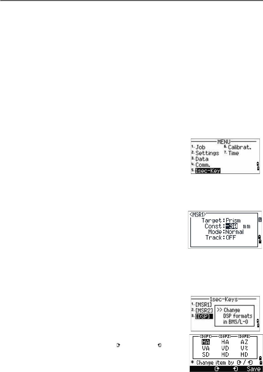
Trimble TS635 Construction Total Station User Guide 101
Menu Screen 5
Uploading coordinates without points
You can upload data without points. If you do not include a point in the format
definition, each line of data is automatically assigned the next available point number.
To help you to select points in the field, make sure that you store an identifier in the CD
field.
The data format cannot include duplicate items. Use PT, N, E, Z, and CD once each in
the data format.
To skip an item in your original file, set the corresponding field to blank.
1sec-Key
Use the 1sec-Key menu to configure the settings for the one-second buttons, [MSR1],
[MSR2], and [DSP].
To access it, press [5] or select 1sec-Keys in the
MENU screen.
[MSR] button settings
There are two [MSR] buttons:
•To change the settings for the [MSR1] button, press [1] or select MSR1.
•To change the settings for the [MSR2] button, press [2] or select MSR2.
Each [MSR] button has four settings.
In the Const and Track field, use the numeric keys to
enter values. In the other fields, use [<] or [>] to change
the settings.
BTip – To quickly access the settings screen, hold down [MSR1] or [MSR2] for one second.
[DSP] button settings
To change the display items in the BMS and in Layout
observation screens, press [2] or select [DSP] in the
1sec-Keys menu.
To move the cursor, use [<], [>], [^] or [v]. To change the
display item, press either the softkey or the softkey.
To save the changes, press [ENT] from the last line of
<DSP3> or select the Save softkey.
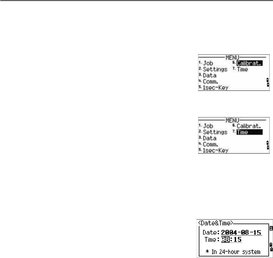
5 Menu Screen
102 Trimble TS635 Construction Total Station User Guide
BTip – To quickly access the DSP settings screen, hold down [DSP] for one second.
Calibration
Use the Calibration screen to calibrate the instrument if
required. To access the Calibration screen, press [6] or
select Calibrat from the MENU screen.
See also Adjusting the calibration, page 106.
Time
Use the Date & Time screen to set the current date and
time.
1. Press [7] or select Time on the MENU screen. The
Date & Time screen appears.
The current date and time settings are displayed.
2. Enter the date in Year-Month-Day format. For example, to change the date to
August 15, 2006 press [2] [0] [0] [6] [ENT] [8] [ENT] [1] [5] [ENT].
If the highlighted part of the field ( for example, the year) is already correct, press
[ENT] to use the current value. For example, if the date is already set to August 20,
2006, and you want to change the date to August 25, 2006, press [ENT] [ENT] [2] [5]
[ENT].
3. To move to the Time field, press [ENT] from the
Date field:
4. Enter the time in 24-hour format. For example, to
set the time to 4:35 PM, press [1] [6] [ENT] [3] [5] [ENT].
5. Do one of the following:
–To finish setting the date and time, press [ENT] in the Minutes field.
–To cancel the changes, press [ESC].

CHAPTER
6
Trimble TS635 Construction Total Station User Guide 103
Checking and Adjusting 6
In this chapter:
QAdjusting the electronic level
QChecking and adjusting the
circular level
QZero point errors of vertical scale
and horizontal angle corrections
QThe instrument constant
QChecking and adjusting the laser
pointer
This chapter describes how to check the
accuracy of the TS635 construction total station,
and if necessary, adjust the required settings.
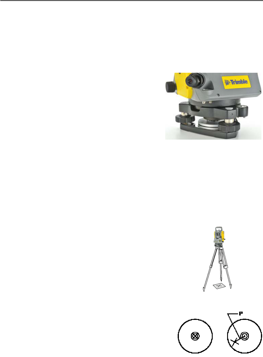
6 Checking and Adjusting
104 Trimble TS635 Construction Total Station User Guide
Adjusting the electronic level
To adjust the electronic level, Zero point errors of vertical scale and horizontal angle
corrections are used. See page 105.
Checking and adjusting the circular level
Once you have checked and adjusted the
electronic level, check the circular level.
If the bubble is not in the center of the level,
use the adjusting pin to rotate the three
adjustment screws of either circular level on
the instrument main body or tribrach until the
bubble is centered.
Checking and adjusting the optical/laser plummet
The optical axis of the plummet must be aligned with the vertical axis of the
instrument.
To check and adjust the optical/laser plummet:
1. Place the instrument on the tripod. You do not have to level the instrument.
2. Place a thick sheet of paper marked with an
X on the ground below the instrument.
3. Do the following:
–Look through the optical plummet and
then adjust the leveling screws until the
image of the X is in the center of the
reticle mark .
–For the laser plummet, adjust the laser
pointer to the X.
4. Rotate the alidade by 180°.
–If the marked image is in the same
position in the center of the reticle
mark, no adjustment is required.
For the laser plummet, if the laser pointer is on the
X, no adjustment is required.
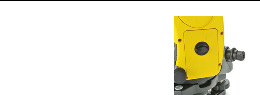
Trimble TS635 Construction Total Station User Guide 105
Checking and Adjusting 6
5. If the image or laser pointer is not in the
same position, adjust the optical or laser
plummet:
a. Use the supplied hexagonal wrench to
turn the adjustment screws until the
image of the X is in Position P. Position
P is the center point of the line
connecting the X and the center of the
reticle mark .
b. Repeat from Step 2. For laser plummet
adjustment, you must remove a cap.
Zero point errors of vertical scale and horizontal angle
corrections
Checking the calibration
1. Set up the instrument on the tripod.
2. Follow the leveling procedures described in Leveling the instrument, page 28.
3. Flip the telescope to the Face-1 position. The display and tangent screws are
facing towards you.
4. Sight a target that is within 45° of the horizontal plane.
5. Read the vertical angle from the VA1 field in the Basic Measurement Screen
(BMS).
6. Rotate the instrument 180° and flip the telescope to the Face-2 position. The
display and tangent screws are turned away from you.
7. Read the vertical angle from the VA2 field.
8. Add the two vertical angles together, VA1 + VA2.
–No adjustment is required if the zero reference for vertical angles (VA zero
setting) is set to Zenith, and VA1 + VA2 equals 360°.
–No adjustment is required if the zero reference for vertical angles (VA zero
setting) is set to Horizon, and VA1 + VA2 is either 180° or 540°.
–An adjustment is required if VA1 + VA2 is not one of the values listed above.
Note – The difference between the vertical angle reading the relevant angle (either 360° for
Zenith, or 180° or 540° for Horizon) is called the altitude constant.
6 Checking and Adjusting
106 Trimble TS635 Construction Total Station User Guide
Adjusting the calibration
1. Press [MENU] and [6]. The calibration screen
appears.
2. Take an F1 measurement to a target on the
horizon. Press [ENT].
The calibration fields for F1 are:
The vertical angle is shown in the V0 dir= Horiz setting.
When you have taken the measurement, the message on the bottom line
changes from DO NOT TOUCH! to Turn to F2.
3. Take an F2 measurement to the same target. Press [ENT].
The TS635 construction total station has horizontal and vertical axis
adjustment:
When the observation on F2 is completed, four
parameters are displayed.
4. Do one of the following:
–To return to the first observation screen,
press [ESC] or select the Redo softkey.
–To set parameters on the instrument, press
[ENT] or select the OK softkey.
5. If ACV, ACH, or Tilt is out of range, OVER
appears. Press any key to return to the first
observation screen.
X1 Face-1 X-axis tilt value
Y1 Face-1 Y-axis tilt value
VA1 Face-1 vertical angle (tilt-off value)
HA1 Face-1 horizontal angle (tilt-off
value)
X2 Face-2 X-axis tilt value
Y2 Face-2 Y-axis tilt value
VA2 Face-2 vertical angle (tilt-off value)
HA2 Face-2 horizontal angle (tilt-off
value)
Trimble TS635 Construction Total Station User Guide 107
Checking and Adjusting 6
The instrument constant
The instrument constant is a numerical value used to automatically correct for the
displacement between the mechanical and electrical centers when measuring
distances. The instrument constant is set at the factory. However, to ensure the highest
operational accuracy, we recommend that you check the instrument constant several
times a year.
The following figure shows the setup to check the instrument constant.
To check the instrument constant, either compare a correctly measured base line with
the distance measured by the EDM, or carry out the following procedure.
1. Set up the instrument at Point P, in as flat an area as possible.
2. Set up a reflector prism at Point Q, 100 m away from Point P. Make sure that you
take the prism constant into account.
3. Measure the distance between Point P and Point Q (PQ).
4. Install a reflector prism on the tripod at Point P.
5. Set up another tripod at Point R, on the line between Point P and Point Q.
6. Transfer the TS635 construction total station to the tripod at Point R.
7. Measure the distance from Point R to Point P (RP), and the distance from Point
R to Point Q (RQ).
8. Calculate the difference between the value of PQ and the value of RP + RQ.
9. Move the TS635 construction total station to other points on the line between
Point P and Point Q.
10. Repeat Step 5 through Step 9 several times.
11. Calculate the average of all the differences.
The error range is within 3 mm. If the error is out of range, contact your dealer.
About 100 m
PQ
PRQ

6 Checking and Adjusting
108 Trimble TS635 Construction Total Station User Guide
Checking and adjusting the laser pointer
The TS635 construction total station uses a red laser beam to measure and as a laser
pointer. The laser pointer is coaxial with the line of sight of the telescope. If the
instrument is well adjusted, the red laser pointer coincides with the line of sight.
External influences such as shock or large temperature fluctuations can displace the
red laser pointer relative to the line of sight.

APPENDIX
A
Trimble TS635 Construction Total Station User Guide 109
Specifications A
In this chapter:
QMeasurement range
QDistance precision
QMeasurement intervals
QAngle measurement
QTilt sensor
QTangent screws
QTribrach
QLevel
QDisplay and keypad
QConnections in the base of
instrument
QBattery pack
QEnvironmental performance
QDimensions
QWeight
QStandard components
QExternal device connector
This appendix details the specifications and
standard components of the TS635 construction
total station. It also describes the connector that
is used to connect the instrument to an external
power source or to communicate with an
external device.

A Specifications
110 Trimble TS635 Construction Total Station User Guide
Main body
Telescope
Measurement range
Distances shorter than 1.5 m (4.92 ft) cannot be measured with this EDM.
Notes –
The target should not receive direct sunlight.
“Reference target” refers to a white, highly reflective material (KGC 90%).
In reflectorless mode, the maximum measurement range is 500 m (1,640 feet).
Tube length 125 mm (4.91 inch)
Magnification 30×
Effective diameter of objective 45 mm (1.77 inch)
EDM 50 mm (1.97 inch)
Image Erect
Field of view 1°20'
2.3 m at 100 m (2.3 ft at 100 ft)
Resolving power 3.0"
Focussing distance 1.5 m to infinity (59 inch to infinity)
Measurement range with no haze, visibility over 40 km (25 miles)
Prism mode
Reflector sheet (5 cm x 5 cm) 300 m (984 ft)
Standard prism (1P) 5,000 m (16,400 ft)
Reflectorless mode
Reference target 300 m (984 ft)

Trimble TS635 Construction Total Station User Guide 111
Specifications A
Distance precision
Measurement intervals
Measurement intervals may vary with the measuring distance or weather conditions;
At the initial measurement, it may take longer.
Precise mode
Prism mode ± (3 + 2 ppm × D) mm
–10 °C through +40 °C (+14 °F through +104 °F)
± (3 + 3 ppm × D) mm
(–20 °C through –10 °C), (+40 °C through +50 °C)
(–4 °F through +14 °F), (+104 °F through +122 °F)
Reflectorless mode ± (3 + 2 ppm × D) mm
–10 °C through +40 °C (+14 °F through +104 °F)
± (3 + 3 ppm × D) mm
(–20 °C to –10 °C), (+40 °C through +50 °C)
(–4 °F through +14 °F), (+104 °F through +122 °F)
Normal mode
Prism mode ± (10 + 5 ppm × D) mm
Reflectorless mode ± (10 + 5 ppm × D) mm
Precise mode
Prism mode 1.5 sec.
Reflectorless mode 1.8 sec.
Normal mode
Prism mode 0.8 sec.
Reflectorless mode 1.0 sec.
Prism offset correction –999 mm to +999 mm
(1 mm step)

A Specifications
112 Trimble TS635 Construction Total Station User Guide
Angle measurement
Tilt sensor
Tangent screws
Tribrach
Level
Optical plumment (Optional)
Reading system Absolute encoder
Diameterial reading on HA
Single reading on VA
360° 1"/5"/10"
400G 0.2 mgon / 1 mgon / 2 mgon
MIL6400 0.005 mil / 0.02 mil / 0.05 mil
DIN18723 accuracy 5"/ 1.5 mgon
Method Liquid-electric detection
Compensation range ±3°
Type Friction clutch endless fine motion
Type Detachable
Electronic level Displayed on the LCD
Circular level vial Sensitivity 10' / 2 mm
Image Erect
Magnification 3x
Field of view 5°
Focussing range 0.5 m (1.6 ft) to infinity

Trimble TS635 Construction Total Station User Guide 113
Specifications A
Laser plummet
Display and keypad
Connections in the base of instrument
Battery pack
Note – Tested at 25 °C (77 °F) (normal temperature). Operation times may vary depending
on the condition and deterioration of the battery.
Wave length 635 nm
Laser class Class 2
Focussing range
8
Laser diameter Approximately 2 mm
Display type Graphical LCD
Resolution 128 × 64
Display illumination Backlight
Keys 25
Communications
Type RS-232C
Maximum baud rate 38400 bps asynchronous
External power supply
input voltage
4.5 V through 5.2 V DC
Output voltage 3.8 V DC rechargeable
Continuous operation time
Continuous distance/angle
measurement
10 hours
Distance/angle measurement every
30 seconds
16 hours
Continuous angle measurement 30 hours
A Specifications
114 Trimble TS635 Construction Total Station User Guide
Environmental performance
Dimensions
Weight
Environmental protection
Standard components
•Instrument main body
•Battery pack (x 2)
•Universal charger, power cord, and adaptors
•Adjustment pin, Allen wrench
•The TS635 Construction Total Station User Guide (this document)
•Carry case
Operating temperature range –20 °C through +50 °C
(–4 °F through +122 °F)
Storage temperature range –25 °C through +60 °C
(–13 °F through +140 °F)
Main unit 149 mm W x 145 mm D x 306 mm H
(6.6 inch W x 6.8 inch D x 13.7 inch H)
Carry case 435 mm W x 206 mm D x 297 mm H
(18.5 inch W x 13.8 inch D x 9.1 inch H)
Main unit (without battery) Approximately 3.5 kg (7.7 lbs)
Battery Approximately 0.1 kg (0.22 lbs)
Carry case Approximately 2.4 kg (5.29 lbs)
Charger and AC adapter Approximately 0.4 kg (0.9 lbs)
Watertight/dust-proof protection IP66

Trimble TS635 Construction Total Station User Guide 115
Specifications A
External device connector
This connector can be used to connect to an external power source or to
communicate with an external device.
Before using the external device connector, make sure that the external device meets
the specifications below.
CCAUTION – Except when connected as shown in the System diagram, page 14, use of the
Hirose HR10A-7P-6P or HR10-7P-6P is at your own risk.
CCAUTION – Use only the male connectors specified above. Using other connectors will
damage the instrument.
The external device connector is a Hirose HR 10A-7R-6S female connector. The
pinouts for connecting the instrument to an external device connector are shown
below:
CCAUTION – Only use the pin connections shown above. Using other connections will
damage the instrument.
CCAUTION – The TS635 total station has different pin assignments from other Construction
total stations.
To connect to an external power source, supply power to Pin 4 (power terminal) and
Pin 5 (ground terminal) on the instrument. The instrument will use the external power
source even if the internal battery packs is attached.
CCAUTION – Make sure that the power supplied is within the rated input range (4.5 V to
5.2 V, 1 A maximum). Power supplied outside this range will damage the instrument.
Input voltage 4.5 V DC to 5.2 V DC
System RS-232C
Signal level ±9 V standard
Maximum baud rate 38400 bps asynchronous
Compatible male connector Hirose HR10A-7P-6P or HR10-7P-6P
Pin Signal Description
1 RxD Receive data (Input)
2 TxD Send data (Output)
3 NC No connection
4VPower
5 GND Ground
6 NC No connection
HRS
16
25
34

A Specifications
116 Trimble TS635 Construction Total Station User Guide
To communicate with an external device, connect the RS-232C signal from the
external device to Pin 1 (input terminal) and to Pin 2 (output terminal) on the
instrument.
Cap the data output/external power input connector securely when the instrument is
not in use. The instrument is not watertight if the cap is detached or not attached
securely, or when the data output/external power input connector is in use.
The instrument can be damaged by static electricity from the human body discharged
through the data output/external power input connector. Before handling the
instrument, touch any other conductive material once to remove static electricity.

APPENDIX
B
Trimble TS635 Construction Total Station User Guide 117
Transferring Coordinate Data B
In this chapter:
QTransferring coordinate data to
the total station
QTransferring coordinate data
from the total station
The TS635 construction total station uses lists of
coordinate data. This chapter describes how to
transfer data between the total station and the
office computer.
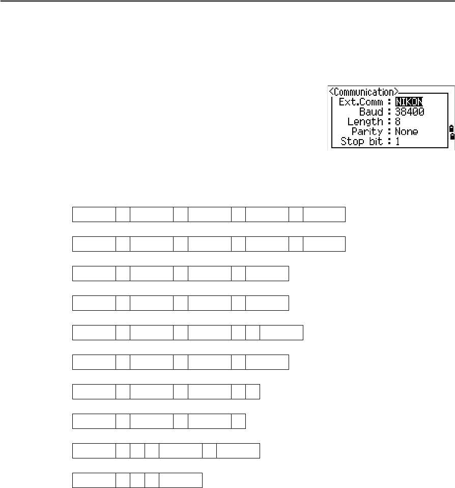
B Transferring Coordinate Data
118 Trimble TS635 Construction Total Station User Guide
Transferring coordinate data to the total station
Settings
To configure the transmission speed and other settings,
press [MENU] and then select Settings / Comm. See
also Communications, page 93.
Record format
You can transfer coordinate records to the TS635 construction total station in the
following formats:
PT ,X ,Y ,Z ,CD
PTXYZCD
PT ,X ,Y ,Z
PTXYZ
PT ,X ,Y ,,CD
PTXYCD
PT ,X ,Y ,,
PT ,X ,Y ,
PT ,,,Z ,CD
PT ,,,Z
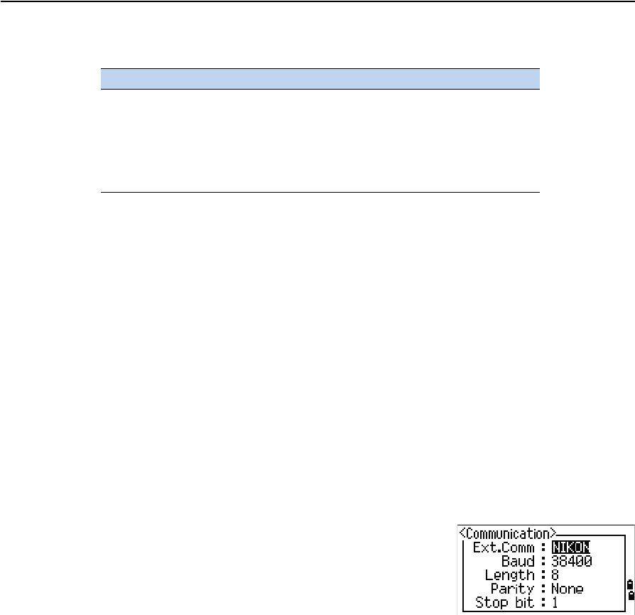
Trimble TS635 Construction Total Station User Guide 119
Transferring Coordinate Data B
The formats use the following codes:
Data example
20100,6606.165,1639.383,30.762,RKBSS
20104,1165611.6800,116401.4200,00032.8080
20105 5967.677 1102.343 34.353 MANHOLE
20106 4567.889 2340.665 33.444 PT1
20107 5967.677 1102.343 34.353
20109,4657.778,2335.667,,PT2
20111,4657.778,2335.667
20113 4657.778 2335.667
20115,,,34.353,MANHOLE
20117,,,33.444
Transferring coordinate data from the total station
Settings
To configure the transmission speed and other settings,
press [MENU] and then select Settings / Comm. See
also Communications, page 93.
Data examples
Nikon coordinate data format
1,100.0000,200.0000,10.0000,
2,200.0000,300.0000,20.0000,
3,116.9239,216.9140,11.8425,TRAIN PLATFORM
4,126.6967,206.2596,11.2539,RAMP
11,100.0045,199.9958,10,0000,
13,116.9203,216.9113,11.7157,
14,126.6955,206.2579,10.9908,
21,100.0103,199.9958,10.0000,
31,100.0013,200.0005,10.0000,
41,100.0224,200.0331,9.9000,
43,116.9263,216,9165,11.8016,CURB
44,126.7042,206.2871,10.8193,DITCH
45,116.9266,216.9160,11.8028,
46,126.7046,206.2845,10.8213,CP POINT
Code Description Length
PT Point number Up to 20 digits
X Actual X coordinate Variable length
Y Actual Y coordinate Variable length
Z Actual Z coordinate Variable length
CD Feature code Up to 16 characters

B Transferring Coordinate Data
120 Trimble TS635 Construction Total Station User Guide

APPENDIX
C
Trimble TS635 Construction Total Station User Guide 121
Error Messages C
In this chapter:
QCogo
QCommunications
QData
QJob manager
QLayout
QPrograms
QRecording data
QSearching
QSettings
QStation setup
QSystem error
The appendix describes the error messages that
may appear when you use the TS635
construction total station.

C Error Messages
122 Trimble TS635 Construction Total Station User Guide
Cogo
NO Result
The system was unable to calculate an area because points were not entered in the
correct order.
Press any key to return to the Cogo menu. Then enter the points in the correct order.
Same Coordinate
The point or coordinate that you entered is identical to the previous input point.
Press any key to return to the point input screen. Then use a different point.
XY-coordinate is required
The input point does not have XY (NE) coordinates.
Press any key to return to the point input screen. Then enter a point that has X and
Ycoordinates.
Communications
If an error is detected while data is being transferred to the TS635 construction total
station, the total station stops the transfer and displays one of the following messages:
Check Data
There are errors in the data that is being transferred to the total station, such as an
alphabetic character in a coordinate field.
Press any key. Then check the specified line in the data.
DUPLICATE PT
CCAUTION – If the existing point is a UP, CC, or MP record, and the point is not referred to
by ST or BS, the existing point will be overwritten by the uploaded record. No error
message appears.
The uploaded data contains a duplicate PT.
Press any button. Then check the specified point in the data.
PT MAX20 chars
The uploaded data contains a PT with a name or number that is longer than 20 digits.
Press any button. Then check the specified line in the data.
XYZ OVERRANGE
The uploaded data contains a coordinate that is longer than 13 digits.
Press any button. Then check the specified line in the data.
Trimble TS635 Construction Total Station User Guide 123
Error Messages C
Data
Can't Edit XYZ from measurement
You have tried to change the coordinates of an SO, SS, or CP record. You cannot change
the coordinates of these records.
Press any button to return to the previous screen.
DELETE Stn-XYZ
You have tried to delete a coordinate record that the current ST or BS refers to. You
must confirm that you want to delete this record.
Job manager
Cannot Assign
You have tried to set the current job as the control file.
Press any button to return to the previous screen. Then select a different job.
Can't Create
There is no space available to create a job or record a point.
Press any button to return to the Job Manager. Then select the DEL softkey to delete
old jobs.
Existing Job
You have entered an existing job name for a new job.
Press any button and then change the name for the new job.
MAX 32Jobs
You are trying to create a new job when the maximum number of jobs (32) is already
stored.
Press any button to return to the Job Manager. Then select the DEL softkey to delete
old jobs.
To... Press...
delete XYZ the DEL softkey
return to the previous screen without deleting XYZ [ESC] or the Abrt softkey

C Error Messages
124 Trimble TS635 Construction Total Station User Guide
Layout
Input Error
The point name style used in the Fr field is not the same as the style used in the To
field. For example, the Fr field style is 1, and the To field style is A200.
Press any button to return to the Fr/To input screen. Then re-enter the point name,
using the same naming style in both fields.
NO Stn Setup
You did not perform a station setup or BS check before entering the Layout function.
CCAUTION – Selecting Continue does not resume the last ST record. You should only
use the Continue option if you are sure that the previous ST coordinates and the
current HA orientation are correct. Otherwise, records in the Stakeout function may not
be correct.
Programs
NO Stn Setup
CCAUTION – Selecting Continue does not resume the last ST record. You should only
use the Continue option if you are sure that the previous ST coordinates and the
current HA orientation are correct. Otherwise, records in the Programs function may
not be correct.
You did not perform a station setup or BS check before entering the Programs
function.
To... Press...
go to the Stn Setup menu [2] or select Stn Setup
return to the Basic Measurement
Screen (BMS)
[ESC]
go to the Stakeout menu [1] or select Continue
To... Press...
go to the Stn Setup menu [2] or select Stn Setup
return to the BMS [ESC]
go to the Programs menu [1] or select Continue
Trimble TS635 Construction Total Station User Guide 125
Error Messages C
Recording data
DATA FULL
The data storage is full.
Press any button to return to the Basic Measurement Screen (BMS). Then:
DUPLICATE PT
The input PT you are trying to record already exists in the current job. An existing
coordinate record cannot be overwritten by measured data.
Press any button to return to the point input screen. Change the setting in the PT field.
Duplicate PT
The input PT you are trying to record already exists in the current job as an SS, SO, or
CP record. An existing SS, SO, or CP record can be overwritten by measured data.
No Open Job
No job is open.
NO Stn Setup
There is no station record in the current job, or a station setup or BS check has not
been done since the program was rebooted.
To... Press...
delete unnecessary data [MENU] and select Data
delete jobs [MENU] and select Job
To... Press...
return to the PT input screen [ESC] or the Abrt softkey
record RAW data and update XYZ
data
the XYZ softkey
record RAW data only the RAW softkey
To... Press...
open the job list, if there are existing
jobs
[1] or select Select job
create a new job [2] or select Create job
return to the previous screen [ESC]
To... Press...
continue recording [1] or select Continue. If there is already an ST
record in the job, the message CO, Use
current orientation appears.
go to the Stn Setup menu [2] or select STN Setup
return to the previous screen [ESC]

C Error Messages
126 Trimble TS635 Construction Total Station User Guide
OVER RANGE
You are trying to record a coordinate with more than 13 digits.
Press any button to return to the previous screen. Then check the setting for the
current ST coordinate.
Searching
PT Not Found
There is no point that matches the criteria entered.
Press any button to return to the point input screen.
This message may appear in any function where the PT/CD is input, such as Station
Setup or Stakeout.
Settings
Job Settings will be changed
You have changed one or more of the following job settings:
•VA zero or HA in the Angle screen (see Angle, page 90)
•Scale, T-P, Sea Lvl, or C&R in the Distance screen (see Distance, page 90)
•Coord or Az Zero in the Coordinates screen (see Coordinate, page 93)
•Angle, Dist, Temp, or Press in the Unit screen (see Unit, page 93)
Note – To record a point using the new settings, create a new job using the new settings.
To... Press...
discard the changes to the job
settings
[ESC] or the Abrt softkey. The current job remains
open.
close the current job and save the
changes to the job settings
[ENT] or the OK softkey.
Trimble TS635 Construction Total Station User Guide 127
Error Messages C
Station setup
Same Coordinate
The input PT or coordinate is identical to the current station in STN/2:Known, or the
same coordinate or point name/number is found in Resection.
Press any button to return to the PT input screen. Then use a different PT.
Space LOW
There is not enough space to record a station when you start any of the Station Setup
functions.
XY-coordinate is required
The input point for ST/BS does not have N/E coordinates.
Press any button to return to the PT input screen. Then use a PT that has N/E
coordinates.
Z-coordinate is required
The input point for Benchmark does not have a Z coordinate.
Press any button to return to the PT input screen. Then use a PT that has a
Z coordinate. See page 68.
System error
=SYSTEM ERROR=
The system has detected an internal error that is related to the lower-level system.
Press any key to turn the instrument off. The system will reboot when this error is
reported. If you still have more points to shoot in the site, turn the instrument on and
repeat the open a job and station setup procedures.
Data stored before this error will be kept safely in the Job file. If the error appears
frequently, please contact your dealer or Trimble Support and report the message that
appears below the =SYSTEM ERROR= line.
To... Press...
return to the BMS press [ESC] or select the Abrt softkey. Select the DEL
softkey in Job Manager to delete old jobs.
continue press [ENT] or select the OK softkey. You may not be
able to record the whole process.

C Error Messages
128 Trimble TS635 Construction Total Station User Guide