Nokia Solutions and Networks T5GX1 UBS CDMA XMI Transceiver at 800 MHz User Manual Exhibit 123a
Nokia Solutions and Networks UBS CDMA XMI Transceiver at 800 MHz Exhibit 123a
Contents
Exhibit 123a

APPLICANT: MOTOROLA
Cellular Networks
FCC ID: IHET5GX1
Commissioning Manual Exhibit
UBS CDMA XMI Transceiver at 800MHz
FCC Filing – UBS CDMA XMI Transceiver at 800MHz (cover page)

1X UBS Macro BTS Optimization/ATP
68P09283A63 -5 AUG 2007
FOA
© 2006, 2007 Motorola, Inc. All Rights R eserv ed

Accuracy
While reasonable efforts have been made to assure the accuracy of this document, Motorola, Inc. assumes no
liability resulting from any inaccuracies or omissions in this document, or from use of the information obtained
herein. Motorola, Inc. reserves the right to make changes to any products described herein to improve reliability ,
function, or design, and reserves the right to revise this document and to make changes from time to time in content
hereof with no obligation to notify any person of revisions or changes. Motorola, Inc. does not assume any liability
arising out of the application or use of any product, software, or circuit described herein; neither does it convey
license under its patent rights or the rights of others. It is possible that this publication may contain references to, or
information about Motorola products (machines and programs), programming, or services that are not announced
in your country . Such references or information must not be construed to mean that Motorola intends to announce
such Motorola products, programming, or services in your country .
Copyrights
This document, Motorola products, and 3rd P arty Software products described in this document may include
or describe copyrighted Motorola and other 3rd P arty supplied computer programs stored in semiconductor
memories or other media. Laws in the United States and other countries preserve for Motorola, its licensors, and
other 3rd P arty supplied software certain exclusive rights for copyrighted material, including the exclusive right
to copy , reproduce in any form, distribute and make derivative works of the copyrighted material. Accordingly ,
any copyrighted material of Motorola, its licensors, or the 3rd P arty software supplied material contained in the
Motorola products described in this document may not be copied, reproduced, reverse engineered, distributed,
merged or modified in any manner without the express written permission of Motorola. Furthermore, the purchase
of Motorola products shall not be deemed to grant either directly or by implication, estoppel, or otherwise, any
license under the copyrights, patents or patent applications of Motorola or other 3rd P arty supplied software,
except for the normal non-exclusive, royalty free license to use that arises by operation of law in the sale of a
product.
A list of 3rd P arty supplied software copyrights are contained in the Supplemental information section of this
document.
Restrictions
Software and documentation are copyrighted materials. Making unauthorized copies is prohibited by law . No part
of the software or documentation may be reproduced, transmitted, transcribed, stored in a retrieval system, or
translated into any language or computer language, in any form or by any means, without prior written permission
of Motorola, Inc.
License Agreements
The software described in this document is the property of Motorola, Inc and its licensors. It is furnished by express
license agreement only and may be used only in accordance with the terms of such an agreement.
High Risk Materials
Components, units, or 3rd P arty products used in the product described herein are NOT fault-tolerant and are NOT
designed, manufactured, or intended for use as on-line control equipment in the following hazardous environments
requiring fail-safe controls: the operation of Nuclear F acilities, Aircraft Navigation or Aircraft Communication
Systems, Air Traffic Control, Life Support, or W eapons Systems (High Risk Activities). Motorola and its supplier(s)
specifically disclaim any expressed or implied warranty of fitness for such High Risk Activities.
T rademarks
Motorola and the Stylized M Logo are registered in the US P atent & Trademark Office. All other product or service
names are the property of their respective owners.
The CE mark confirms Motorola, Inc. statement of compliance with EU directives applicable to this product. Copies
of the Declaration of Compliance and installation information in accordance with the requirements of EN50385 can
be obtained from the local Motorola representative or by contacting the Customer Network Resolution Center
(CNRC). The 24 hour telephone numbers are listed at h t t p s : / / m y n e t w o r k s u p p o r t . m o t o r o l a . c o m . Select Customer
Network Resolution Center contact information. Alternatively if you do not have access to CNRC or the
internet, contact the Local Motorola Office.
FOA A UG 2007

T a b l e
o f
C o n t e n t s
Contents
■■■■■■■■■■■■■■■■■■■■■■■■■■■■■■■■■■■■■■■■■■■■■■■■■■■■■■■■■■■■■■
■
■
■
■
1X UBS Macro BTS Optimization/ATP
Revision history ......................................... 2
Version information ..................................... 2
Resolution of Service Requests . . . . . . . . . . . . . . . . . . . . . . . . . . . . . . . 2
Incorporation of Change Notices . . . . . . . . . . . . . . . . . . . . . . . . . . . . . . . 2
General information ....................................... 3
Purpose ........................................... 3
Cross references ....................................... 3
Text conventions ....................................... 4
Contacting Motorola ....................................... 5
24–hour support ....................................... 5
Questions and comments .................................. 5
Errors ............................................ 5
Security advice .......................................... 6
W arnings, cautions, and notes . . . . . . . . . . . . . . . . . . . . . . . . . . . . . . . . . . 7
W arnings ........................................... 7
Cautions ........................................... 7
Notes ............................................ 7
Safety .............................................. 8
General safety ........................................ 8
Electromagnetic energy ................................... 8
Caring for the environment . . . . . . . . . . . . . . . . . . . . . . . . . . . . . . . . . . . 9
In EU countries ....................................... 9
In non -EU countries ..................................... 9
CMM labeling and disclosure table . . . . . . . . . . . . . . . . . . . . . . . . . . . . . . . 10
Motorola document set ..................................... 11
Ordering documents and CD -ROMs . . . . . . . . . . . . . . . . . . . . . . . . . . . . . 11
Document banner definitions . . . . . . . . . . . . . . . . . . . . . . . . . . . . . . . . 11
Data encryption ....................................... 11
Supplemental information . . . . . . . . . . . . . . . . . . . . . . . . . . . . . . . . . . . . 12
Third P arty computer software and trademarks . . . . . . . . . . . . . . . . . . . . . . . 12
Chapter 1: Introduction
Scope and Layout ........................................ 1 - 2
Scope ............................................ 1 - 2
Assumptions ......................................... 1 - 2
Audience ........................................... 1 - 2
Intended Reader Profile ................................... 1 - 3
Publication Composition ................................... 1 - 3
Purpose of Optimization ..................................... 1 - 4
Why Optimize? ........................................ 1 - 4
What is Calibration? ..................................... 1 - 4
68P09283A63 -5 i
A UG 2007 FOA
Contents
What Happens During Calibration? . . . . . . . . . . . . . . . . . . . . . . . . . . . . . 1 - 4
When to P erform UBS Acceptance T esting . . . . . . . . . . . . . . . . . . . . . . . . . . 1 - 5
Periodic Optimization .................................... 1 - 6
General T est Equipment Selection, Calibration, and Operation Requirements . . . . . . . . . . 1 - 7
Policy ............................................ 1 - 7
T est Equipment Calibration . . . . . . . . . . . . . . . . . . . . . . . . . . . . . . . . . 1 - 7
Test Cable Calibration .................................... 1 - 7
Equipment W arm–up ..................................... 1 - 8
Required T est Equipment and Software . . . . . . . . . . . . . . . . . . . . . . . . . . . . . 1 - 9
Overview ........................................... 1 - 9
LMF Computer and Software . . . . . . . . . . . . . . . . . . . . . . . . . . . . . . . . 1 - 9
Communications System Analyzer CDMA/Analog . . . . . . . . . . . . . . . . . . . . . . 1 - 10
Optional Test Equipment ................................... 1 - 12
Required Documents ....................................... 1 - 13
Required Documents ..................................... 1 - 13
Reference Documents .................................... 1 - 13
Abbreviations and Acronyms . . . . . . . . . . . . . . . . . . . . . . . . . . . . . . . . . 1 - 13
UBS Equipment Identification . . . . . . . . . . . . . . . . . . . . . . . . . . . . . . . . . . 1 - 17
Introduction ......................................... 1 - 17
UBS Component Identification . . . . . . . . . . . . . . . . . . . . . . . . . . . . . . . . 1 - 21
Chapter 2: Preliminary Operations
Introduction ........................................... 2 - 2
Cell Site Types ........................................ 2 - 2
NEC Files .......................................... 2 - 2
Site Equipage V erification . . . . . . . . . . . . . . . . . . . . . . . . . . . . . . . . . . 2 - 2
Pre -P owerup Tests ........................................ 2 - 3
Objective ........................................... 2 - 3
Test Equipment ....................................... 2 - 3
Cabling Inspection ...................................... 2 - 3
DC Power Pre -T est ...................................... 2 - 3
Initial Power -up Tests ...................................... 2 - 5
Power -up Procedures .................................... 2 - 5
Common P ower Supply V erification . . . . . . . . . . . . . . . . . . . . . . . . . . . . . 2 - 5
Initial P ower -up (Frame) . . . . . . . . . . . . . . . . . . . . . . . . . . . . . . . . . . . 2 - 6
Chapter 3: LMF Operation
Optimization/Calibration Introduction . . . . . . . . . . . . . . . . . . . . . . . . . . . . . . 3 - 2
Introduction ......................................... 3 - 2
Preparing the LMF ........................................ 3 - 3
Overview ........................................... 3 - 3
W inLMF File Structure Overview . . . . . . . . . . . . . . . . . . . . . . . . . . . . . . 3 - 3
W inLMF Directory ...................................... 3 - 4
W inLMF Operating System Installation . . . . . . . . . . . . . . . . . . . . . . . . . . . 3 - 5
LMF to UBS Connection ..................................... 3 - 6
LMF to UBS Connection ................................... 3 - 6
Using W inLMF .......................................... 3 - 7
Basic W inLMF Operation .................................. 3 - 7
The LMF Display and the UBS . . . . . . . . . . . . . . . . . . . . . . . . . . . . . . . . 3 - 8
Graphical User Interface Overview . . . . . . . . . . . . . . . . . . . . . . . . . . . . . 3 - 8
Understanding GUI Operation . . . . . . . . . . . . . . . . . . . . . . . . . . . . . . . . 3 - 8
Command Line Interface Overview . . . . . . . . . . . . . . . . . . . . . . . . . . . . . 3 - 8
Logging into a UBS ..................................... 3 - 9
LMF Menus and Options ................................... 3 - 18
Logging Out ......................................... 3 - 28
On -Line Help ......................................... 3 - 29
ii 68P09283A63 -5
FOA A UG 2007
1X UBS Macro B T S Optimization/A TP Contents
Download Code to UBS ..................................... 3 - 30
Prerequisites ......................................... 3 - 30
Download Procedure ..................................... 3 - 30
Test Equipment Set Up ...................................... 3 - 32
Connecting T est Equipment to the UBS . . . . . . . . . . . . . . . . . . . . . . . . . . . 3 - 32
T est Equipment GPIB Address Settings . . . . . . . . . . . . . . . . . . . . . . . . . . . 3 - 32
Supported T est Equipment . . . . . . . . . . . . . . . . . . . . . . . . . . . . . . . . . . 3 - 33
T est Equipment Preparation . . . . . . . . . . . . . . . . . . . . . . . . . . . . . . . . . 3 - 34
Equipment W arm -up ..................................... 3 - 34
Automatic Cable Calibration . . . . . . . . . . . . . . . . . . . . . . . . . . . . . . . . . 3 - 35
Manual Cable Calibration . . . . . . . . . . . . . . . . . . . . . . . . . . . . . . . . . . 3 - 35
Set -up for TX Calibration . . . . . . . . . . . . . . . . . . . . . . . . . . . . . . . . . . 3 - 35
Setup for ATP ........................................ 3 - 40
T est Equipment Connection to the LMF . . . . . . . . . . . . . . . . . . . . . . . . . . . . . 3 - 45
T est Equipment Connection . . . . . . . . . . . . . . . . . . . . . . . . . . . . . . . . . 3 - 45
Addressing Methods ..................................... 3 - 47
T est Equipment Selection . . . . . . . . . . . . . . . . . . . . . . . . . . . . . . . . . . . . 3 - 48
T est Equipment Selection . . . . . . . . . . . . . . . . . . . . . . . . . . . . . . . . . . 3 - 48
Manual and Autodetect Selection . . . . . . . . . . . . . . . . . . . . . . . . . . . . . . 3 - 48
Selecting T est Equipment . . . . . . . . . . . . . . . . . . . . . . . . . . . . . . . . . . 3 - 48
Selection Procedures .................................... 3 - 48
Test Set Calibration ....................................... 3 - 55
T est Set Calibration Background . . . . . . . . . . . . . . . . . . . . . . . . . . . . . . . 3 - 55
Calibration Procedures Included . . . . . . . . . . . . . . . . . . . . . . . . . . . . . . . 3 - 56
Calibrate T est Equipment Function (Except Agilent E4406A and
Anritsu
MT8212B) . . . . . 3 - 56
Calibrating the
Anritsu
MT8212B .............................. 3 - 57
Setting and Editing Generator Calibration Data . . . . . . . . . . . . . . . . . . . . . . . . . 3 - 62
Generator Calibration Data . . . . . . . . . . . . . . . . . . . . . . . . . . . . . . . . . 3 - 62
Cable Calibration ........................................ 3 - 64
Calibrating Cables Overview . . . . . . . . . . . . . . . . . . . . . . . . . . . . . . . . . 3 - 64
Cable Calibration Set–up Diagrams . . . . . . . . . . . . . . . . . . . . . . . . . . . . . 3 - 64
Calibrate T est Cabling using Communications System Analyzer . . . . . . . . . . . . . . . 3 - 64
Calibrate T est Cabling Using Signal Generator & Spectrum Analyzer . . . . . . . . . . . . 3 - 69
Setting Cable Loss V alues . . . . . . . . . . . . . . . . . . . . . . . . . . . . . . . . . . 3 - 72
Chapter 4: Acceptance Test Procedures
Introduction to ATP ....................................... 4 - 2
Introduction ......................................... 4 - 2
Acceptance T est Procedures - TX & RX . . . . . . . . . . . . . . . . . . . . . . . . . . . . . 4 - 4
Reduced and Full ATP .................................... 4 - 4
TX Audit and RS SI Tests ................................... 4 - 4
Automated ATP ....................................... 4 - 7
Automated A TP T est Options . . . . . . . . . . . . . . . . . . . . . . . . . . . . . . . . . 4 - 7
Required Test Equipment .................................. 4 - 8
ATP Test Prerequisites .................................... 4 - 8
Antenna Connectors ..................................... 4 - 9
Recommended Tests ..................................... 4 - 9
TX/RX ATP Test Procedure .................................. 4 - 9
Individual Tests ......................................... 4 - 14
TX and RX Testing ...................................... 4 - 14
Individual Tests ....................................... 4 - 14
TX Spectral Purity Transmit Mask Acceptance T est . . . . . . . . . . . . . . . . . . . . . . . 4 - 17
TX Mask Test ........................................ 4 - 17
TX W aveform Quality (Rho) Acceptance T est . . . . . . . . . . . . . . . . . . . . . . . . . . . 4 - 18
Rho Test ........................................... 4 - 18
TX Pilot Time Offset Acceptance T est . . . . . . . . . . . . . . . . . . . . . . . . . . . . . . 4 - 19
PTO Acceptance Test ..................................... 4 - 19
68P09283A63 -5 iii
A UG 2007 FOA
Contents
TX Code Domain P ower/Noise Floor Acceptance T est . . . . . . . . . . . . . . . . . . . . . . 4 - 21
Code Domain Power Test ................................... 4 - 21
RX Frame Error R ate (FER) Acceptance T est . . . . . . . . . . . . . . . . . . . . . . . . . . 4 - 23
FER Test ........................................... 4 - 23
Continuous W aveform Mode . . . . . . . . . . . . . . . . . . . . . . . . . . . . . . . . . . . 4 - 24
Objective ........................................... 4 - 24
Unlock Continuous W aveform Mode . . . . . . . . . . . . . . . . . . . . . . . . . . . . . 4 - 24
Lock Continuous W aveform Mode . . . . . . . . . . . . . . . . . . . . . . . . . . . . . . 4 - 25
Generate ATP Report ...................................... 4 - 26
Background ......................................... 4 - 26
ATP Report .......................................... 4 - 26
Chapter 5: Leave the Site
Configuring Backhaul ...................................... 5 - 2
Introduction ......................................... 5 - 2
Backhaul Configuration Procedure . . . . . . . . . . . . . . . . . . . . . . . . . . . . . . 5 - 2
Using the LMF Configure Backhaul Advanced Screen . . . . . . . . . . . . . . . . . . . . 5 - 4
Prepare to Leave the Site .................................... 5 - 7
External T est Equipment Removal . . . . . . . . . . . . . . . . . . . . . . . . . . . . . . 5 - 7
LMF Removal ........................................ 5 - 7
Reset All Devices and Initialize Site Remotely . . . . . . . . . . . . . . . . . . . . . . . . 5 - 8
Appendix A: Data Sheets
Optimization/A TP Checklist . . . . . . . . . . . . . . . . . . . . . . . . . . . . . . . . . . . A - 2
V erification of T est Equipment Used . . . . . . . . . . . . . . . . . . . . . . . . . . . . . A - 2
Checklist ........................................... A - 3
Appendix B: FRU Optimization/ATP Matrix
FRU Optimization/A TP T est Matrix . . . . . . . . . . . . . . . . . . . . . . . . . . . . . . . . B - 2
Usage & Background .................................... B - 2
UBS Optimization Required . . . . . . . . . . . . . . . . . . . . . . . . . . . . . . . . . B - 2
Detailed Reduced ATP .................................... B - 2
Detailed Optional Full A TP T est Matrix . . . . . . . . . . . . . . . . . . . . . . . . . . . B - 2
Appendix C: CDMA Operating Frequency
800 MHz CDMA Operating Frequency Programming Information . . . . . . . . . . . . . . . . C - 2
Introduction ......................................... C - 2
800 MHz Channels ...................................... C - 2
800 MHz Channel Center Frequencies . . . . . . . . . . . . . . . . . . . . . . . . . . . . C - 5
1900 MHz CDMA Operating Frequency Programming Information . . . . . . . . . . . . . . . C - 6
Introduction ......................................... C - 6
1900 MHz Channels ..................................... C - 6
1900 MHz Channel Center Frequencies . . . . . . . . . . . . . . . . . . . . . . . . . . . C - 8
CDMA Operating Frequency Programming Information . . . . . . . . . . . . . . . . . . . . . C - 9
Introduction ......................................... C - 9
2100 MHz Channels ..................................... C - 10
Calculating 2100 MHz Channel Center Frequencies . . . . . . . . . . . . . . . . . . . . . C - 11
Appendix D: Test Equipment Preparation
T est Equipment Preparation . . . . . . . . . . . . . . . . . . . . . . . . . . . . . . . . . . . D - 2
Purpose ........................................... D - 2
GPIB addresses ....................................... D - 2
Calibration actions ...................................... D - 2
iv 68P09283A63 -5
FOA A UG 2007
1X UBS Macro B T S Optimization/A TP Contents
Agilent E7495A/B T est Equipment Setup . . . . . . . . . . . . . . . . . . . . . . . . . . . . . D - 4
Initial Requirement ..................................... D - 4
Using the Agilent E7495A/B with the LMF . . . . . . . . . . . . . . . . . . . . . . . . . . D - 4
Connection .......................................... D - 4
P ower Sensor Calibration . . . . . . . . . . . . . . . . . . . . . . . . . . . . . . . . . . D - 4
Cable Calibration ...................................... D - 6
V erifying and Setting GPIB Addresses – Agilent E4406A Transmitter T ester . . . . . . . . . . . D - 7
V erifying and Setting GPIB Addresses – Agilent E4432B Signal Generator . . . . . . . . . . . . D - 9
V erifying and Setting GPIB Addresses – Advantest R3267 Spectrum Analyzer . . . . . . . . . . D - 11
V erifying and Setting GPIB Addresses – Advantest R3562 Signal Generator . . . . . . . . . . . D - 13
V erifying and Setting GPIB Addresses – Agilent 8935 Series E6380 T est Set . . . . . . . . . . . D - 14
V erifying and Setting GPIB Addresses – Gigatronics 8541C P ower Meter . . . . . . . . . . . . D - 16
V erifying and Setting GPIB Addresses – Agilent E4418 P ower Meter . . . . . . . . . . . . . . D - 18
V erifying and Setting GPIB Addresses – RS232 GPIB Interface Box . . . . . . . . . . . . . . . D - 20
T est Equipment Calibration – Agilent 4406 Self -alignment . . . . . . . . . . . . . . . . . . . . D - 21
T est Equipment Calibration – Gigatronics 8542 P ower Meter . . . . . . . . . . . . . . . . . . D - 22
Appendix E: Optimization and Calibration Procedures
Introduction to Calibration . . . . . . . . . . . . . . . . . . . . . . . . . . . . . . . . . . . . E - 2
Overview ........................................... E - 2
Optimization Process Summary . . . . . . . . . . . . . . . . . . . . . . . . . . . . . . . E - 2
T ake Control of UBS Resources . . . . . . . . . . . . . . . . . . . . . . . . . . . . . . . . . E - 4
UBS Control ......................................... E - 4
T aking Control of UBS Resources . . . . . . . . . . . . . . . . . . . . . . . . . . . . . . E - 4
Code Syncing to the UBS .................................... E - 5
General Information ..................................... E - 5
Bay Level Offset Calibration . . . . . . . . . . . . . . . . . . . . . . . . . . . . . . . . . . . E - 6
Introduction ......................................... E - 6
RF P ath Bay Level Offset Calibration . . . . . . . . . . . . . . . . . . . . . . . . . . . . E - 6
When to TX Audit ...................................... E - 6
TX Path Calibration ..................................... E - 6
BLO Calibration Data File . . . . . . . . . . . . . . . . . . . . . . . . . . . . . . . . . . E - 7
T est Equipment Set -up for RF P ath Calibration . . . . . . . . . . . . . . . . . . . . . . . E - 7
Transmit (TX) P ath Calibration Description . . . . . . . . . . . . . . . . . . . . . . . . . E - 8
TX Calibration and the LMF . . . . . . . . . . . . . . . . . . . . . . . . . . . . . . . . . E - 8
UBS Redundancy/Alarm T esting . . . . . . . . . . . . . . . . . . . . . . . . . . . . . . . . . E - 10
Test Equipment Setup .................................... E - 10
GPS and QHSO Redundancy/Alarm T ests . . . . . . . . . . . . . . . . . . . . . . . . . . E - 10
Alarms Testing .......................................... E - 12
Alarm Verification ...................................... E - 12
Alarm Reporting Display . . . . . . . . . . . . . . . . . . . . . . . . . . . . . . . . . . . E - 12
Purpose ........................................... E - 14
Alarm input and output information . . . . . . . . . . . . . . . . . . . . . . . . . . . . . E - 14
Customer Alarm Input V erification . . . . . . . . . . . . . . . . . . . . . . . . . . . . . . E - 16
Pin and Signal Information for Alarm Connectors . . . . . . . . . . . . . . . . . . . . . . E - 17
Appendix F: MSO Calibration
MSO Calibration ......................................... F - 2
MSO Calibration Status ................................... F - 2
MSO Calibration Procedure . . . . . . . . . . . . . . . . . . . . . . . . . . . . . . . . . F - 2
Appendix G: SSI Loopback Connector Information
SSI Loopback Connector ..................................... G - 2
Purpose ........................................... G - 2
Required Parts ........................................ G - 2
68P09283A63 -5 v
A UG 2007 FOA
Contents
S SI Span Loopback Connector . . . . . . . . . . . . . . . . . . . . . . . . . . . . . . . . G - 2
S SI Customer Input / Output Loopback Connector . . . . . . . . . . . . . . . . . . . . . . G - 4
vi 68P09283A63 -5
FOA A UG 2007

L i s t
o f
F i g u r e s
List of Figures
■■■■■■■■■■■■■■■■■■■■■■■■■■■■■■■■■■■■■■■■■■■■■■■■■■■■■■■■■■■■■■
■
■
■
■
Figure 1 -1: Null Modem Cable Detail . . . . . . . . . . . . . . . . . . . . . . . . . . . . . . 1 - 10
Figure 1 -2: UBS Macro Low Capacity / Low Tier . . . . . . . . . . . . . . . . . . . . . . . . . 1 - 18
Figure 1 -3: Low Capacity / High Tier . . . . . . . . . . . . . . . . . . . . . . . . . . . . . . 1 - 19
Figure 1-4: Mid -Capacity .................................... 1 - 20
Figure 1 -5: UBS Site Span I/O P anel . . . . . . . . . . . . . . . . . . . . . . . . . . . . . . . 1 - 22
Figure 1 -6: XMI Front P anel . . . . . . . . . . . . . . . . . . . . . . . . . . . . . . . . . . . 1 - 23
Figure 1 -7: DMI Front P anel . . . . . . . . . . . . . . . . . . . . . . . . . . . . . . . . . . . 1 - 24
Figure 3 -1: LMF F older Structure . . . . . . . . . . . . . . . . . . . . . . . . . . . . . . . . 3 - 4
Figure 3 -2: LMF Connection Detail . . . . . . . . . . . . . . . . . . . . . . . . . . . . . . . 3 - 6
Figure 3-3: W inLMF Icon .................................... 3 - 10
Figure 3 -4: Local T erminal (Login Screen) . . . . . . . . . . . . . . . . . . . . . . . . . . . . 3 - 10
Figure 3 -5: Network Interface Selection . . . . . . . . . . . . . . . . . . . . . . . . . . . . . 3 - 12
Figure 3-6: FTP Server ..................................... 3 - 13
Figure 3 -7: Frame Selection . . . . . . . . . . . . . . . . . . . . . . . . . . . . . . . . . . . 3 - 14
Figure 3 -8: Local T erminal GUI . . . . . . . . . . . . . . . . . . . . . . . . . . . . . . . . . 3 - 15
Figure 3 -9: Invasive Mode Selection . . . . . . . . . . . . . . . . . . . . . . . . . . . . . . . 3 - 16
Figure 3 -10: Invasive Mode Message W indow . . . . . . . . . . . . . . . . . . . . . . . . . . 3 - 17
Figure 3-11: BTS Menu ..................................... 3 - 18
Figure 3-12: Select Menu .................................... 3 - 19
Figure 3 -13: Device Menu - DMI (HDModem) . . . . . . . . . . . . . . . . . . . . . . . . . . 3 - 20
Figure 3 -14: Device Menu - XMI . . . . . . . . . . . . . . . . . . . . . . . . . . . . . . . . . 3 - 21
Figure 3 -15: T ools Menu - Options . . . . . . . . . . . . . . . . . . . . . . . . . . . . . . . . 3 - 22
Figure 3 -16: T ests Menu - RX . . . . . . . . . . . . . . . . . . . . . . . . . . . . . . . . . . 3 - 23
Figure 3 -17: T ests Menu - TX . . . . . . . . . . . . . . . . . . . . . . . . . . . . . . . . . . 3 - 24
Figure 3 -18: Util Menu - P ower Meter . . . . . . . . . . . . . . . . . . . . . . . . . . . . . . 3 - 25
Figure 3 -19: Util Menu - T est Equipment . . . . . . . . . . . . . . . . . . . . . . . . . . . . 3 - 26
Figure 3 -20: Util Menu - Examine . . . . . . . . . . . . . . . . . . . . . . . . . . . . . . . . 3 - 27
Figure 3 -21: Util Menu - Edit . . . . . . . . . . . . . . . . . . . . . . . . . . . . . . . . . . 3 - 28
Figure 3-22: Help Screen .................................... 3 - 29
Figure 3 -23: TX Calibration T est Setup – Agilent 8935 . . . . . . . . . . . . . . . . . . . . . . 3 - 36
Figure 3 -24: TX Calibration T est Setup – Agilent E4406A and Advantest R3267 . . . . . . . . . 3 - 37
Figure 3 -25: TX Calibration T est Setup – Agilent E7495A . . . . . . . . . . . . . . . . . . . . 3 - 38
Figure 3 -26: TX Calibration T est Setup –
Anritsu
MT8212B ................... 3 - 39
Figure 3 -27: A TP T est Setup – Agilent E4432B/8935 and Agilent E4432B/E4406A . . . . . . . . 3 - 41
Figure 3 -28: A TP T est Setup – Advantest R3267/3562 . . . . . . . . . . . . . . . . . . . . . . 3 - 42
Figure 3 -29: A TP T est Setup – Agilent E7495A or E7495B . . . . . . . . . . . . . . . . . . . . 3 - 43
Figure 3 -30: A TP T est Setup –
Anritsu
MT8212B ......................... 3 - 44
Figure 3 -31: Cable Calibration T est Setup – Agilent 8935 . . . . . . . . . . . . . . . . . . . . 3 - 66
Figure 3 -32: Cable Calibration T est Setup – Advantest R3267/R3562,E4406A/E4432B, and
Agilent E4432/8935 Series E6380A . . . . . . . . . . . . . . . . . . . . . . . . . . . . . . . 3 - 67
Figure 3 -33: Cable Calibration T est Setup – Agilent E7495A and E7495B . . . . . . . . . . . . 3 - 68
Figure 3 -34: Cable Calibration T est Setup –
Anritsu
MT8212B .................. 3 - 69
Figure 3 -35: TX and Duplexed RX Cable Calibration . . . . . . . . . . . . . . . . . . . . . . . 3 - 70
Figure 3 -36: Non -Duplex RX Cable Calibration . . . . . . . . . . . . . . . . . . . . . . . . . 3 - 72
Figure 4 -1: TX Audit Signal . . . . . . . . . . . . . . . . . . . . . . . . . . . . . . . . . . . 4 - 5
68P09283A63 -5 vii
A UG 2007 FOA
List of Figures
Figure 4 -2: TX T est Options Screen . . . . . . . . . . . . . . . . . . . . . . . . . . . . . . . 4 - 11
Figure 4 -3: TX Mask V erification Spectrum Analyzer Display (1900 MHz) . . . . . . . . . . . . 4 - 17
Figure 4-4: Rho Signal ...................................... 4 - 18
Figure 4 -5: Pilot Only Signal . . . . . . . . . . . . . . . . . . . . . . . . . . . . . . . . . . . 4 - 20
Figure 4 -6: Code Domain P ower and Noise Floor Levels . . . . . . . . . . . . . . . . . . . . . 4 - 22
Figure 5 -1: Configure Backhaul Basic Screen . . . . . . . . . . . . . . . . . . . . . . . . . . 5 - 3
Figure 5 -2: Configure Backhaul Advanced Screen . . . . . . . . . . . . . . . . . . . . . . . . 5 - 6
Figure C -1: 800 MHz Frequency Spectrum (CDMA Allocation) . . . . . . . . . . . . . . . . . C - 4
Figure C -2: 1900 MHz Frequency Spectrum (CDMA Allocation) . . . . . . . . . . . . . . . . . C - 7
Figure C -3: 2100 MHz Frequency Spectrum (CDMA Allocation) . . . . . . . . . . . . . . . . . C - 10
Figure D -1: Agilent E7495A/B Pre -P ower Sensor Calibration Connection . . . . . . . . . . . . D - 5
Figure D -2: Agilent E7495A/B P ower Sensor Calibration Connection . . . . . . . . . . . . . . D - 5
Figure D -3: Setting Agilent E4406A GPIB Address . . . . . . . . . . . . . . . . . . . . . . . . D - 7
Figure D -4: Setting Agilent E4432B GPIB Address . . . . . . . . . . . . . . . . . . . . . . . . D - 9
Figure D -5: Setting Advantest R3267 GPIB Address . . . . . . . . . . . . . . . . . . . . . . D - 11
Figure D -6: Advantest R3562 GPIB Address Switch Setting . . . . . . . . . . . . . . . . . . . D - 13
Figure D -7: Setting Agilent 8935 T est Set GPIB Address . . . . . . . . . . . . . . . . . . . . . D - 14
Figure D -8: Gigatronics 8541C P ower Meter Detail . . . . . . . . . . . . . . . . . . . . . . . D - 16
Figure D -9: Agilent E4418B P ower Meter V erify and Set/Change GPIB Address . . . . . . . . . D - 18
Figure D -10: RS232 GPIB Interface Box . . . . . . . . . . . . . . . . . . . . . . . . . . . . . D - 20
Figure D -11: Agilent E4406A Self -alignment . . . . . . . . . . . . . . . . . . . . . . . . . . . D - 21
Figure D -12: Gigatronics 8541C P ower Meter Calibration . . . . . . . . . . . . . . . . . . . . D - 22
Figure E -1: Alarm Connector Location . . . . . . . . . . . . . . . . . . . . . . . . . . . . . . E - 13
Figure E -2: Alarm Connector Pin Numbering . . . . . . . . . . . . . . . . . . . . . . . . . . E - 15
Figure F -1: BTS Menu - Enter Invasive Mode . . . . . . . . . . . . . . . . . . . . . . . . . . F - 3
Figure F -2: Message W indow . . . . . . . . . . . . . . . . . . . . . . . . . . . . . . . . . . F - 3
Figure F -3: BTS Menu - MSO CAL Status . . . . . . . . . . . . . . . . . . . . . . . . . . . . F - 3
Figure F -4: Read MSO Cal Status . . . . . . . . . . . . . . . . . . . . . . . . . . . . . . . . F - 3
Figure F -5: Select MSO Calibration . . . . . . . . . . . . . . . . . . . . . . . . . . . . . . . F - 3
Figure F -6: Select Clock Reference . . . . . . . . . . . . . . . . . . . . . . . . . . . . . . . F - 3
Figure F -7: MSO Calibration (Invasive Mode) . . . . . . . . . . . . . . . . . . . . . . . . . . F - 3
Figure F -8: Read MSO Status . . . . . . . . . . . . . . . . . . . . . . . . . . . . . . . . . . F - 3
Figure F -9: Exit Local T erminal . . . . . . . . . . . . . . . . . . . . . . . . . . . . . . . . . F - 3
Figure F -10: MSO Status (Non -Invasive Mode) . . . . . . . . . . . . . . . . . . . . . . . . . F - 3
Figure G -1: Loopback Connector . . . . . . . . . . . . . . . . . . . . . . . . . . . . . . . . G - 2
Figure G -2: S SI Span Loopback Connector W iring Diagram . . . . . . . . . . . . . . . . . . . G - 4
Figure G -3: S SI CIO Loopback Connector W iring Diagram . . . . . . . . . . . . . . . . . . . G - 6
viii 68P09283A63 -5
FOA A UG 2007

L i s t
o f
T a b l e s
List of Tables■■■■■■■■■■■■■■■■■■■■■■■■■■■■■■■■■■■■■■■■■■■■■■■■■■■■■■■■■■■■■■
■
■
■
■
T able 1 -1: CDMA LMF T est Equipment Support T able . . . . . . . . . . . . . . . . . . . . . . 1 - 10
T able 1 -2: Abbreviations and Acronyms . . . . . . . . . . . . . . . . . . . . . . . . . . . . . 1 - 14
T able A -1: T est Equipment Used Checklist . . . . . . . . . . . . . . . . . . . . . . . . . . . . A - 2
T able A -2: Procedure Checklist . . . . . . . . . . . . . . . . . . . . . . . . . . . . . . . . . A - 3
T able B -1: When Optimization is Required . . . . . . . . . . . . . . . . . . . . . . . . . . . . B - 2
T able B -2: Full A TP T est Matrix . . . . . . . . . . . . . . . . . . . . . . . . . . . . . . . . . B - 3
T able C -1: 800 MHz Channel Allocations . . . . . . . . . . . . . . . . . . . . . . . . . . . . . C - 2
T able C -2: 800 MHz TX and RX Channel Center Frequencies . . . . . . . . . . . . . . . . . . C - 5
T able C -3: 1900 MHz Band Class 1 Channel Allocations . . . . . . . . . . . . . . . . . . . . . C - 6
T able C -4: 1900 MHz TX and RX Channel Center Frequencies . . . . . . . . . . . . . . . . . . C - 8
T able C -5: 2100 MHz TX and RX Channel Center Frequencies . . . . . . . . . . . . . . . . . . C - 11
T able E -1: Connector Pinout for Cable T IP 1–12 OP 1–4 . . . . . . . . . . . . . . . . . . . . . E - 17
T able E -2: Connector Pinout for Cable T IP13–24 OP5–8 . . . . . . . . . . . . . . . . . . . . . E - 18
T able G -1: P arts Required to F abricate Loopback Connector . . . . . . . . . . . . . . . . . . . G - 2
T able G -2: S SI Span Loopback Connector Pinouts . . . . . . . . . . . . . . . . . . . . . . . . G - 3
T able G -3: S SI CIO Loopback Connector Pinouts . . . . . . . . . . . . . . . . . . . . . . . . G - 5
68P09283A63 -5 ix
A UG 2007 FOA
List of T ables
x 68P09283A63 -5
FOA A UG 2007

L i s t
o f
P r o c e d u r e s
List of Procedures
■■■■■■■■■■■■■■■■■■■■■■■■■■■■■■■■■■■■■■■■■■■■■■■■■■■■■■■■■■■■■■
■
■
■
■
Procedure 2 -1: DC P ower Pre–test (UBS) . . . . . . . . . . . . . . . . . . . . . . . . . . . . 2 - 4
Procedure 2 -2: Procedure for Common P ower Supply V erification . . . . . . . . . . . . . . . . 2 - 5
Procedure 2 -3: Procedure for Initial P ower–up (Frame) . . . . . . . . . . . . . . . . . . . . . 2 - 6
Procedure 3 -1: CD ROM Installation . . . . . . . . . . . . . . . . . . . . . . . . . . . . . . . 3 - 5
Procedure 3 -2: LMF to UBS Connection Procedure . . . . . . . . . . . . . . . . . . . . . . . 3 - 6
Procedure 3 -3: UBS GUI Login Procedure . . . . . . . . . . . . . . . . . . . . . . . . . . . . 3 - 11
Procedure 3 -4: UBS GUI Logout Procedure . . . . . . . . . . . . . . . . . . . . . . . . . . . 3 - 29
Procedure 3 -5: Download Code . . . . . . . . . . . . . . . . . . . . . . . . . . . . . . . . . 3 - 31
Procedure 3 -6: Selecting a COM P ort for GPIB or Serial T est Equipment Connection . . . . . . 3 - 45
Procedure 3 -7: Disconnect and Reconnect the LMF and the Active COM P ort . . . . . . . . . . 3 - 46
Procedure 3 -8: Manually Selecting T est Equipment - GPIB Interface . . . . . . . . . . . . . . 3 - 49
Procedure 3 -9: Autodetecting T est Equipment - GPIB Interface . . . . . . . . . . . . . . . . . 3 - 50
Procedure 3 -10: Manually Selecting T est Equipment - Serial Interface . . . . . . . . . . . . . 3 - 52
Procedure 3 -11: Autodetecting T est Equipment - Serial Interface . . . . . . . . . . . . . . . . 3 - 52
Procedure 3 -12: Manually Selecting T est Equipment - Network Interface . . . . . . . . . . . . 3 - 53
Procedure 3 -13: Autodetecting T est Equipment - Network Interface . . . . . . . . . . . . . . . 3 - 54
Procedure 3 -14: Calibrate T est Equipment - P ower Measurement Zeroing . . . . . . . . . . . . 3 - 57
Procedure 3 -15:
Anritsu
MT8212B Multi -function T est Set Zero Out P ower Meter . . . . . . . . 3 - 58
Procedure 3 -16:
Anritsu
MT8212B Multi -function T est Set TX Analyzer Calibration . . . . . . . 3 - 59
Procedure 3 -17:
Anritsu
MT8212B Multi -function T est Set CW Generator Calibration . . . . . . 3 - 60
Procedure 3 -18: Set or Edit Generator Calibration Data . . . . . . . . . . . . . . . . . . . . . 3 - 62
Procedure 3 -19: Automatic Cable Calibration . . . . . . . . . . . . . . . . . . . . . . . . . . 3 - 65
Procedure 3 -20: Calibrating TX and Duplexed RX Cables Using Signal Generator and Spectrum
Analyzer ............................................. 3 - 70
Procedure 3 -21: Calibrating RX Cables Using a Signal Generator and Spectrum Analyzer . . . 3 - 71
Procedure 3 -22: Setting Cable Loss V alues . . . . . . . . . . . . . . . . . . . . . . . . . . . 3 - 73
Procedure 4 -1: Procedure for TX Audit . . . . . . . . . . . . . . . . . . . . . . . . . . . . . 4 - 4
Procedure 4 -2: Procedure for RS SI Acceptance T esting . . . . . . . . . . . . . . . . . . . . . 4 - 6
Procedure 4 -3: Setup T est Equipment — TX Output V erify/Control T ests . . . . . . . . . . . . 4 - 9
Procedure 4 -4: All TX/RX A TP T est Procedure . . . . . . . . . . . . . . . . . . . . . . . . . . 4 - 9
Procedure 4 -5: All TX A TP T est . . . . . . . . . . . . . . . . . . . . . . . . . . . . . . . . . 4 - 11
Procedure 4 -6: All RX A TP T est . . . . . . . . . . . . . . . . . . . . . . . . . . . . . . . . . 4 - 13
Procedure 4 -7: Procedure to Unlock Continuous W aveform Mode . . . . . . . . . . . . . . . . 4 - 24
Procedure 4 -8: Procedure to Lock Continuous W aveform Mode . . . . . . . . . . . . . . . . . 4 - 25
Procedure 4 -9: Generating an A TP Report . . . . . . . . . . . . . . . . . . . . . . . . . . . . 4 - 27
Procedure 5 -1: Fractional Span Backhaul Configuration Procedure . . . . . . . . . . . . . . . 5 - 3
Procedure 5 -2: Resetting Backhaul P arameters to their Default V alues . . . . . . . . . . . . . 5 - 5
Procedure 5 -3: External T est Equipment Removal Procedure . . . . . . . . . . . . . . . . . . 5 - 7
Procedure 5 -4: LMF T ermination and Removal Procedure . . . . . . . . . . . . . . . . . . . . 5 - 7
Procedure 5 -5: Reset UBS Devices and Remote Site Initialization . . . . . . . . . . . . . . . . 5 - 8
Procedure D -1: Set IP Address on Agilent E7495A/B test set . . . . . . . . . . . . . . . . . . D - 4
Procedure D -2: E7495A/B P ower Sensor Calibration . . . . . . . . . . . . . . . . . . . . . . . D - 4
Procedure D -3: V erify and Set/Change Agilent E4406A Transmitter T ester GPIB Address . . . . D - 7
Procedure D -4: V erify and Change Agilent E4432B Signal Generator GPIB Address . . . . . . . D - 9
Procedure D -5: V erify and Set/Change Advantest R3267 GPIB Address . . . . . . . . . . . . . D - 11
68P09283A63 -5 xi
A UG 2007 FOA
List of Procedures
Procedure D -6: V erify and Set/Change Agilent 8935 Series E6380 T est Set GPIB Address . . . . D - 14
Procedure D -7: V erify and Set/Change Gigatronics 8541C P ower Meter GPIB Address . . . . . D - 16
Procedure D -8: V erify and Set/Change Agilent E4418 P ower Meter GPIB Address . . . . . . . . D - 18
Procedure D -9: Agilent E4406A Self -alignment (Calibration) . . . . . . . . . . . . . . . . . . D - 21
Procedure D -10: Calibrate Gigatronics 8542 P ower Meter . . . . . . . . . . . . . . . . . . . . D - 22
Procedure E -1: T est Equipment Setup (RF P ath Calibration) . . . . . . . . . . . . . . . . . . . E - 7
Procedure E -2: T est Equipment Setup for Redundancy/Alarm T ests . . . . . . . . . . . . . . . E - 10
Procedure E -3: GPS and QHSO/MSO Redundancy/Alarm T ests . . . . . . . . . . . . . . . . . E - 11
Procedure E -4: Customer Alarm Input V erification . . . . . . . . . . . . . . . . . . . . . . . . E - 16
Procedure F -1: Procedure to Calibrate the MSO . . . . . . . . . . . . . . . . . . . . . . . . . F - 2
xii 68P09283A63 -5
FOA A UG 2007

A b o u t
T h i s
M a n u a l
1X UBS Macro BTS Optimization/ATP■■■■■■■■■■■■■■■■■■■■■■■■■■■■■■■■■■■■■■■■■■■■■■■■■■■■■■■■■■■■■■
■
■
■
■
68P09283A63 -5 1
A UG 2007 FOA

R evision history
Revision history■■■■■■■■■■■■■■■■■■■■■■■■■■■■■■■■■■■■■■■■■■■■■■■■■■■■■■■■■■■■■■
■
■
Version information
The following shows the status of this document since it was first released.
Issue
Date of issue
Remarks
1 AUG 2007
Initial DRAFT
2 AUG 2007
DRAFT Update
3 AUG 2007
Preliminary - Added 800 and 1.9 MHz information to
Appendix C and Created Appendix G for S SI Span
and CIO Loopback Connector information.
4 AUG 2007
Preliminary - More Engineering updates.
5
SEP 2007
FOA - Added in EV -DO A TP reference to Chapter 4.
Resolution of Service Requests
The following Service Requests are resolved in this document:
Service
Request
CMBP Number
Remarks
NA NA
Initial release
Incorporation of Change Notices
The following Change Notices (CN) are incorporated in this document:
CN Date CN Number
T itle
NA NA NA
2 68P09283A63 -5
FOA A UG 2007

Gener al information
General information
■■■■■■■■■■■■■■■■■■■■■■■■■■■■■■■■■■■■■■■■■■■■■■■■■■■■■■■■■■■■■■
■
■
Purpose
Motorola cellular communications documents are intended to instruct and assist personnel in
the operation, installation and maintenance of the Motorola cellular infrastructure equipment
and ancillary devices. It is recommended that all personnel engaged in such activities be
properly trained by Motorola.
Motorola disclaims all liability whatsoever , implied or express, for any risk of damage, loss or
reduction in system performance arising directly or indirectly out of the failure of the customer ,
or anyone acting on the customer’s behalf , to abide by the instructions, system parameters,
or recommendations made in this document.
These documents are not intended to replace the system and equipment training offered by
Motorola. They can be used to supplement and enhance the knowledge gained through such
training.
If this document was obtained when attending a Motorola training course, it will
not be updated or amended by Motorola. It is intended for TRAINING P URPOSES
ONL Y . If it was supplied under normal operational circumstances, to support a major
software release, then corrections are supplied automatically by Motorola and posted
on the Motorola customer website.
Cross references
References made to external publications are shown in italics. Other cross references,
emphasized in blue text in electronic versions, are active links to the references.
This document is divided into numbered chapters that are divided into sections. Sections are
not numbered, but are individually named at the top of each page, and are listed in the table of
contents.
68P09283A63 -5 3
A UG 2007 FOA

Gener al information
Text conventions
The following conventions are used in the Motorola cellular infrastructure documents to
represent keyboard input text, screen output text, and special key sequences.
Input
Characters typed in at the keyboard are shown like this.
Items of interest within a command appear like this.
Output
Messages, prompts, file listings, directories, utilities, and environmental
variables that appear on the screen are shown like this.
Items of interest within a screen display appear like this.
Special key sequences
Special key sequences are represented as follows:
CTRL-c or CTRL+C
Press the Ctrl and Ckeys at the same time.
CTRL-SHIFT-c or
CTRL+SHIFT+C
Press the Ctrl ,Shift , and Ckeys at the same time.
ALT-f or ALT+F
Press the Alt and Fkeys at the same time.
ALT+SHIFT+F11
Press the Alt ,Shift and F11 keys at the same time.
¦Press the pipe symbol key .
RETURN or ENTER
Press the Return or Enter key .
4 68P09283A63 -5
FOA A UG 2007
Contacting Motorola
Contacting Motorola■■■■■■■■■■■■■■■■■■■■■■■■■■■■■■■■■■■■■■■■■■■■■■■■■■■■■■■■■■■■■■
■
■
Motorola appreciates feedback from the users of our documents.
24–hour support
If you have problems regarding the operation of your equipment, contact the Customer Network
Resolution Center (CNRC) for immediate assistance. The 24–hour telephone numbers are listed
at https://mynetworksupport.motorola.com . Select Customer Network Resolution Center
contact information . Alternatively if you do not have access to CNRC or the internet, contact
the Local Motorola Office.
Questions and comments
Send questions and comments regarding user documentation to the email address:
mydocs@motorola.com .
Errors
T o report a documentation error , call the CNRC (Customer Network Resolution Center) and
provide the following information to enable CNRC to open an SR (Service Request):
•The document type
•The document title, part number , and revision character
•The page number with the error
•A detailed description of the error and if possible the proposed solution
68P09283A63 -5 5
A UG 2007 FOA
Securit y advice
Security advice■■■■■■■■■■■■■■■■■■■■■■■■■■■■■■■■■■■■■■■■■■■■■■■■■■■■■■■■■■■■■■
■
■
Motorola systems and equipment provide security parameters that can be configured by the
operator based on their particular operating environment. Motorola recommends setting and
using these parameters following industry recognized security practices. Security aspects
to be considered are protecting the confidentiality , integrity , and availability of information
and assets. Assets include the ability to communicate, information about the nature of the
communications, and information about the parties involved.
In certain instances, Motorola makes specific recommendations regarding security practices.
The implementation of these recommendations and final responsibility for the security of the
system lies with the operator of the system.
Contact the Customer Network Resolution Center (CNRC) for assistance. The 24–hour
telephone numbers are listed at https://mynetworksupport.motorola.com . Select Customer
Network Resolution Center contact information , from the menu located to the left of the
Login box. Alternatively if you do not have access to CNRC or the internet, contact the Local
Motorola Office.
6 68P09283A63 -5
FOA A UG 2007

W arnings, cautions, and notes
Warnings, cautions, and notes■■■■■■■■■■■■■■■■■■■■■■■■■■■■■■■■■■■■■■■■■■■■■■■■■■■■■■■■■■■■■■
■
■
The following describes how warnings and cautions are used in this document and in all
documents of this Motorola document set.
Warnings
W arnings precede instructions that contain potentially hazardous situations. W arnings are
used to alert the reader to possible hazards that could cause loss of life or physical injury . A
warning has the following format:
W arning text and consequence for not following the instructions in the w arning.
Cautions
Cautions precede instructions and are used when there is a possibility of damage to systems,
software, or individual items of equipment within a system. However , this damage presents
no danger to personnel. A caution has the following format:
Caution text and consequence for not following the instructions in the caution.
Notes
A note means that there is a possibility of an undesirable situation or provides additional
information to help the reader understand a topic or concept. A note has the following format:
Note text.
68P09283A63 -5 7
A UG 2007 FOA

Safet y
Safety
■■■■■■■■■■■■■■■■■■■■■■■■■■■■■■■■■■■■■■■■■■■■■■■■■■■■■■■■■■■■■■
■
■
General safety
The following general safety guidelines apply to Motorola equipment:
•The power jack and mating plug of the power cable must meet International
Electrotechnical Commission (IEC) safety standards.
Refer to
Grounding Guideline for Cellular R adio Installations – 68P81150E62
.
•P ower down or unplug the equipment before servicing.
•Using non -Motorola parts for repair could damage the equipment or void warranty .
Contact Motorola W arranty and Repair for service and repair instructions.
•P ortions of Motorola equipment may be damaged from exposure to electrostatic discharge.
Use precautions to prevent damage.
Electromagnetic energy
Relevant standards (USA and EC) applicable when working with RF equipment are:
•
ANSI IEEE C95.1 -1991, IEEE Standard for Safety Levels with Respect to Human Exposure
to R adio Frequency Electromagnetic Fields, 3 kHz to 300 GHz.
•Council recommendation of 12 July 1999 on the limitation of exposure of the general
public to electromagnetic fields (0 Hz to 300 GHz) (1999/519/EC) and respective national
regulations.
•
Directive 2004/40/EC of the European P arliament and of the Council of 29 April 200
4 on
the minimum health and safety requirements regarding the exposure of workers to the
risks arising from physical agents (electromagnetic fields) (18th individual Directive within
the meaning of Article 16(1) of Directive 89/391/EEC).
8 68P09283A63 -5
FOA A UG 2007

Caring for the en vironment
Caring for the environment■■■■■■■■■■■■■■■■■■■■■■■■■■■■■■■■■■■■■■■■■■■■■■■■■■■■■■■■■■■■■■
■
■
The following information describes national or regional requirements for the disposal of
Motorola supplied equipment and for the approved disposal of surplus packaging.
Contact the Customer Network Resolution Center (CNRC) for assistance. The 24–hour
telephone numbers are listed at https://mynetworksupport.motorola.com . Select Customer
Network Resolution Center contact information . Alternatively if you do not have access
to CNRC or the internet, contact the Local Motorola Office.
In EU countries
The following information is provided to enable regulatory compliance with the European Union
(EU) directives identified and any amendments made to these directives when using Motorola
equipment in EU countries.
Disposal of Motorola equipment
European Union (EU) Directive 2002/96/EC W aste Electrical and Electronic Equipment (WEEE)
Do not dispose of Motorola equipment in landfill sites. In the EU , Motorola in conjunction
with a recycling partner ensures that equipment is collected and recycled according to the
requirements of EU environmental law .
Disposal of surplus packaging
European P arliament and Council Directive 94/62/EC P ackaging and P ackaging W aste
Do not dispose of surplus packaging in landfill sites. In the EU , it is the individual recipient’s
responsibility to ensure that packaging materials are collected and recycled according to the
requirements of EU environmental law .
In non -EU countries
In non -EU countries, dispose of Motorola equipment and all surplus packaging in accordance
with national and regional regulations.
68P09283A63 -5 9
A UG 2007 FOA
CMM labeling and disclosure table
CMM labeling and disclosure table■■■■■■■■■■■■■■■■■■■■■■■■■■■■■■■■■■■■■■■■■■■■■■■■■■■■■■■■■■■■■■
■
■
The P eople’s Republic of China require that our products comply with China Management
Methods (CMM) environmental regulations. (China Management Methods refers to the
regulation
Management Methods for Controlling P ollution by Electronic Information Products
.)
T wo items are used to demonstrate compliance; the label and the disclosure table.
The label is placed in a customer visible position on the product.
•Logo 1 means the product contains no substances in excess of the maximum concentration
value for materials identified in the China Management Methods regulation.
•Logo 2 means that the product may contain substances in excess of the maximum
concentration value for materials identified in the China Management Methods regulation,
and has an Environmental Friendly Use P eriod (EFUP) in years, fifty years in the example
shown.
Logo 1 Logo 2
The Environmental Friendly Use P eriod (EFUP) is the period (in years) during which the T oxic
and Hazardous Substances (T&HS) contained in the Electronic Information Product (EIP)
will not leak or mutate causing environmental pollution, or bodily injury from the use of the
EIP . The EFUP indicated by the Logo 2 label applies to a product and all its parts. Certain
field -replaceable parts, such as battery modules, can have a different EFUP and are marked
separately .
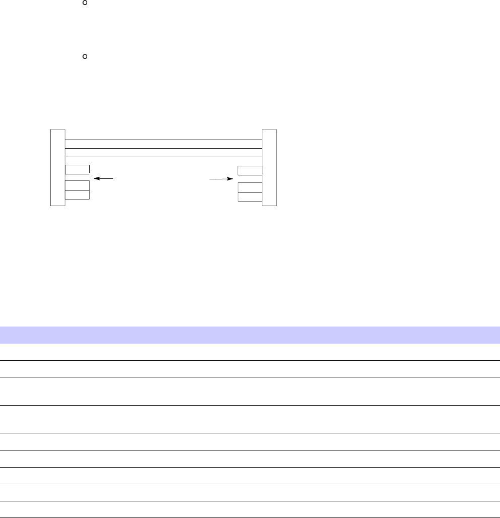
The Disclosure table is intended only to communicate compliance with China requirements.
It is not intended to communicate compliance with EU RoHS or any other environmental
requirements.
10 68P09283A63 -5
FOA A UG 2007
Motorola document set
Motorola document set■■■■■■■■■■■■■■■■■■■■■■■■■■■■■■■■■■■■■■■■■■■■■■■■■■■■■■■■■■■■■■
■
■
The Motorola document sets provide the information to operate, install, and maintain the
Motorola equipment.
Ordering documents and CD -ROMs
W ith internet access available, to view , download, or order documents (original or revised), visit
the Motorola Lifecycles Customer web page at https://mynetworksupport.motorola.com , or
contact your Motorola account representative.
W ithout internet access available, order hard copy documents or CD -ROMs with your Motorola
Local Office or Representative.
If Motorola changes the content of a document after the original printing date, Motorola
publishes a new version with the same part number but a different revision character .
Document banner denitions
A banner (oversized text on the bottom of the page, for example, PRELIMINARY — UNDER
DEVELOPMENT ) indicates that some information contained in the document is not yet approved
for general customer use.
Data encryption
In order to avoid electronic eavesdropping, data passing between certain elements in the
network is encrypted. In order to comply with the export and import requirements of particular
countries, this encryption occurs at different levels as individually standardized, or may not be
present at all in some parts of the network in which it is normally implemented. The document
set, of which this document is a part, covers encryption as if fully implemented. Because the
rules differ in individual countries, limitations on the encryption included in the particular
software being delivered, are covered in the Release Notes that accompany the individual
software release.
68P09283A63 -5 11
A UG 2007 FOA

Supplemental information
Supplemental information■■■■■■■■■■■■■■■■■■■■■■■■■■■■■■■■■■■■■■■■■■■■■■■■■■■■■■■■■■■■■■
■
■
Third Party computer software and trademarks
Computer software
The following is a list of the 3rd party computer software copyrights contained within this
Motorola product.
Company Copyright
Apache Software F oundation* Copyright 1999-2007 All rights reserved.
* Publicly A vailable Software
Trademarks
Java™ T echnology and/or J2ME™: Java and all other Java -based marks are trademarks or
registered trademarks of Sun Microsystems, Inc. in the U .S . and other countries.
UNIX® : UNIX is a registered trademark of The Open Group in the United States and other
countries.
Microsoft®, W indows®,. W indows Me®, and W indows XP™: Microsoft, W indows and W indows
Me are registered trademarks of Microsoft Corporation; W indows XP is a trademark of
Microsoft Corporation.
Cisco®, Cisco IOS®, and IOS®: Cisco, Cisco IOS , and IOS are registered trademarks of Cisco
Systems, Inc. and/or its affiliates in the U .S . and certain other countries.
Anritsu™, FlexCal™, InstaCal™ and Cell Master™: Anritsu, FlexCal, InstaCal, and Cell Master
are trademarks of Anritsu Company .
12 68P09283A63 -5
FOA A UG 2007

C h a p t e r
1
Introduction
■■■■■■■■■■■■■■■■■■■■■■■■■■■■■■■■■■■■■■■■■■■■■■■■■■■■■■■■■■■■■■
■
■
■
■
68P09283A63 -5 1 -1
A UG 2007 FOA

Scope and La y out Chapter 1: Introduction
Scope and Layout■■■■■■■■■■■■■■■■■■■■■■■■■■■■■■■■■■■■■■■■■■■■■■■■■■■■■■■■■■■■■■
■
■
Scope
The procedures in this manual require the use of Local Maintenance F acilit y (LMF)
application softw are v ersion 2.20.x.x or later .
This publication provides information pertaining to the optimization, calibration, and acceptance
testing of the UBS Macro . Throughout the manual UBS Macro will be referred to as UBS .
The equipment shown in many of the figures is typical. The actual appearance may
vary slightly .
Assumptions
This document assumes that the UBS and cabling have been installed according to the following
manuals:
•
Frame Mounting Guide; 68P09226A18
, which covers the physical
bolt down
of all
equipment frames.
•
1X UBS Macro BTS Hardware Installation; 68P09283A62
, which covers installation and
cabling configurations for the UBS Macro .
Audience
Motorola has attempted to incorporate into this document the many customer suggestions and
comments received. Additionally , an attempt has been made to ensure that the scope of the
document supports both the novice and expert site technician and engineer with the information
required to successfully perform the task at hand. If , in some areas, the manual seems to cover
a subject with too much or not enough detail, please keep this in mind.
1 -2 68P09283A63 -5
FOA A UG 2007
1X UBS Macro B T S Optimization/A TP Scope and La y out
Intended Reader Prole
The information in this manual set is intended for use by cellular communications personnel in
the initial installation and configuration, as well as the day -to -day operation and maintenance
of a UBS .
The user of this information must have a general understanding of telephony , as used in the
operation of the Public Switched T elephone Network (PSTN), and must be familiar with these
concepts as they are applied in the cellular and mobile/portable radio telephone maintenance
environment.
The user also must have a working knowledge of W indows 2000 or W indows XP™.
Publication Composition
This publication covers the following areas.
•Introduction: preliminary background information (such as component and subassembly
locations and UBS layouts) to be considered by the Cellular Field Engineer (CFE) before
optimization or tests are performed.
•Preliminary Operations: UBS subassemblies, pre–power up tests, initial power application,
and power–up tests for the UBS after installation.
•Optimization: code syncing all UBS processor boards, test equipment setup and calibration,
UBS verification, radio frequency (RF) path verification, and RF calibration as necessary .
•Field V erification: A t the site the UBS is assembled per the installation manual and tested
using TX Audit and RS SI procedures.
•Acceptance T est Procedures (A TP): automated A TP scripts executed by the LMF and used
to verify all major transmit (TX) and receive (RX) performance characteristics on all UBS
equipment. Includes generating an A TP report. Using the full A TP is optional.
•Prepare to Leave the Site: site turnover process after A TP is completed.
•Basic Troubleshooting: procedures to perform when an A TP fails, as well as when incorrect
results are obtained during logon, test equipment operation, audit, and Global P ositioning
System (GPS) operation. These tests are typically used to isolate faults down to the module
level. Also provided is additional information necessary to better understand equipment
operation.
•Appendices containing data sheets to be filled out manually by the CFE at the site,
optimization/A TP matrix, output power data tables, CDMA operating frequency
programming information, and manual test setup information. .
68P09283A63 -5 1 -3
FOA A UG 2007

Purpose of Optimization Chapter 1: Introduction
Purpose of Optimization
■■■■■■■■■■■■■■■■■■■■■■■■■■■■■■■■■■■■■■■■■■■■■■■■■■■■■■■■■■■■■■
■
■
Why Optimize?
Proper optimization, also known as RF calibration or calibration, ensures that:
•Accurate downlink RF power levels are transmitted from the site.
•Accurate uplink signal strength determinations are made by the site.
What is Calibration?
Calibration compensates for the site -specific cabling and normal equipment variations. Site
calibration takes into account the combined losses of the cables and the gain/loss characteristics
and built -intolerances of each UBS do not accumulate and cause improper site operation.
UBS systems are fully calibrated prior to leaving the factory . Normal installations will not
require additional calibration. Only those installations that deviate significantly from that
described in the installation manual will require site calibration.
Calibration at the site is an option for the UBS . Motorola provides this capability if
the customer needs to perform calibration of one or more carriers.
What Happens During Calibration?
Overview
During calibration, the accumulated path loss or gain is first determined for each RF transmit
path in the UBS . These transmit path loss or gain values are then stored in a database along
with RF receive path default values.
RF Path Denitions
F or definitions of the UBS transmit (TX) and receive (RX) paths, see
What is Bay Level Offset
Calibration?
in the Bay Level Offset Calibration section.
1 -4 68P09283A63 -5
FOA A UG 2007
1X UBS Macro B T S Optimization/A TP Purpose of Optimization
UBS Calibration
Calibration of the UBS will not be performed at the site. A t the factory the XMI (Transceiver
Module Internal) is calibrated to a predetermined output level prior to installation in the UBS .
Using RF Path Gain/Loss Values
Since the XMI power levels are calibrated at the factory , only site–specific antenna feed line loss
and antenna gain characteristics need to be factored in by the CFE when determining required
site Effective R adiated P ower (ERP) output power levels.
When to Perform UBS Acceptance Testing
This section summarizes Motorola -recommended UBS transmit RF path calibration, forward
and reverse RF path integrity and operation verification, and other acceptance testing. Specific
calibration and testing recommendations are included for troubleshooting and for use after the
following listed installation/upgrade activities:
•New UBS installation
•Site RF re -configurations or repairs
New Installations Objectives
•V erify forward (transmit) RF paths
•V erify reverse (receive) RF path performance
•V erify HDModem operation for a new BTS installation
Recommended Actions
P erform the following actions after initial power -up, code syncing, and verifying GPS operation:
•TX Audit of all transmit RF paths to verify UBS calibration is within tolerance
•P erform RS SI on both RF receive paths
•P erform any other acceptance tests required to demonstrate compliance with applicable
regulatory requirements.
Additional Action for a New UBS Installation
In addition to RF acceptance testing, the following non -RF setup and verification actions must
be performed at a new UBS site:
•Configure Backhaul
•Customer Input/Output verification
•Span Line Loopback T est
68P09283A63 -5 1 -5
FOA A UG 2007
Purpose of Optimization Chapter 1: Introduction
Periodic Optimization
P eriodic RF optimization or frequency calibration of a UBS Macro site is not typically required.
1 -6 68P09283A63 -5
FOA A UG 2007
1X UBS Macro B T S Optimization/A TP Gener al T est Equipment Selection, Calibr ation, and Oper ation R equirements
General Test Equipment Selection, Calibration, and
Operation Requirements
■■■■■■■■■■■■■■■■■■■■■■■■■■■■■■■■■■■■■■■■■■■■■■■■■■■■■■■■■■■■■■
■
■
Policy
General Requirements – T o ensure consistent, reliable, and repeatable UBS calibration
results, test equipment and software meeting the following technical criteria should be used
for UBS calibration.
T est equipment substitution – T est equipment can be substituted with other test equipment
models, but substitute items must meet the same technical specifications. All test equipment
models selected for use in UBS calibration and acceptance testing must be supported by the
LMF .
Measurement variances and test equipment substitution – It is the responsibility of the
customer to account for any measurement variances and/or additional losses/inaccuracies
which can be introduced as a result of test equipment item substitutions. Before beginning
UBS calibration or troubleshooting, make sure that the test equipment needed is on–hand and
operating properly .
Test Equipment Calibration
Optimal system performance and capacity depend on regular support equipment service and
calibration prior to its use for UBS calibration. F ollow the original equipment manufacturer
(OEM) recommended maintenance and calibration schedules closely .
Test Cable Calibration
On–site cable calibration – T est cables can make critical differences in calibration accuracy .
Motorola recommends that cable calibration be run at every UBS with the complete test
equipment set. This method compensates for test cable insertion loss within the test equipment
set itself . No other allowance for test cable insertion loss needs to be made during the
performance of UBS calibration or acceptance tests.
In–shop cable characterization – Another method to account for cable loss is by entering
it into the LMF prior to the calibration procedure. This method requires accurate test cable
characterization using shop test equipment. Characterized cables should be tagged with the
characterization information, and the measured losses entered into the LMF before performing
UBS calibration.
68P09283A63 -5 1 -7
FOA A UG 2007
Gener al T est Equipment Selection, Calibr ation, and Oper ation R equirements Chapter 1: Introduction
Equipment Warm–up
A fter arriving at the a site, the test equipment should be plugged in and turned on to allow warm
up and stabilization for as long as possible. The following test equipment items must be warmed
up for a minimum of 60 minutes prior to use for UBS calibration.
•Communications T est Set
•P ower Meter
1 -8 68P09283A63 -5
FOA A UG 2007
1X UBS Macro B T S Optimization/A TP R equired T est Equipment and Softw are
Required Test Equipment and Software■■■■■■■■■■■■■■■■■■■■■■■■■■■■■■■■■■■■■■■■■■■■■■■■■■■■■■■■■■■■■■
■
■
Overview
T est equipment and software described in this section is required for the calibration and
acceptance testing procedures. Common tools such as screwdrivers and frame keys are also
needed. Read the operators manual for all test equipment items to understand their individual
operation before using them for calibration or acceptance testing.
LMF Computer and Software
LMF Hardware Requirements
An LMF computer platform that meets the following minimum requirements (or better) is
recommended:
•533 MHz (1 GHz or higher recommended) P entium processor
•W indows 2000 or W indows XP operating system
•4 GB internal hard disk drive or larger
•Color display with 1024 x 768
•Memory requirements: 256 MB (500 MB recommended)
•CD/D VD drive
•Serial port COM 1
•Serial port COM 2 for SC™6XX and serial versions of SC™3XX
•Ethernet Hub or Switch (recommended with 10Base2 port, for example 3Com®
OfficeConnect® Ethernet Hub 4C) 10Base2/10BaseT Converter (only if switch doesn’t
have 10Base2 port, for example Unicom ETP -20038T)
LMF Software
The Local Maintenance F acility (LMF) application program is a graphical user interface
(GUI)–based software tool. This product is specifically designed to provide cellular
communications field personnel with the capability to support the following UBS operations:
•Installation
•Maintenance
•Calibration
68P09283A63 -5 1 -9
FOA A UG 2007
R equired T est Equipment and Softw are Chapter 1: Introduction
RS–232 to GPIB Interface
•National Instruments GPIB–232CT–A is used to interface the LMF to the test equipment.
•Standard RS–232 cable can be used with the following modifications (see Figure 1 -1 )
This solution passes only the 3 minimum electrical connections between the LMF
and the General Purpose Information Bus (GPIB) interface. The control signals are
jumpered as enabled on both ends of the RS–232 cable (9–pin D). TX and RX signals
are crossed as Null Modem effect. Pin 5 is the ground reference.
Short pins 7 and 8 together , and short pins 1, 4, and 6 together on each connector .
Figure 1 -1 Null Modem Cable Detail
ti-cdma-00088.eps
5
3
2
7
8
1
4
6
GND
RX
TX
RTS
CTS
RSD/DCD
DTR
GND
TX
RX
RTS
CTS
RSD/DCD
DTR
5
2
3
7
8
1
4
6
DSR DSR
FW00362
9-PIN D-FEMALE 9-PIN D-FEMALE
ON BOTH CONNECTORS
SHORT PINS 7, 8;
SHORT PINS 1, 4, AND 6
Communications System Analyzer CDMA/Analog
Table 1 -1 CDMA LMF T est Equipment Support T able
Item Description
T est Capability
T est Sets
Agilent 8935 (formerly HP8935)
Communication T est Set CDMA 2000 T esting
Agilent E4406A (with E4432B) Communications Analyzer with Agilent
E4432B CDMA Signal Generator
CDMA 2000 testing
Advantest R3267 Analyzer (with
R3562)
Communications Analyzer with Advantest
R3562 Generator
CDMA 2000 testing
Agilent E7495A/B
Communications test set CDMA 2000 testing
Anritsu™ MT8212B
Multi-purpose test set
CDMA 2000 testing
P ower Meters
Gigatronix 8541C
P ower Meter
Agilent E4418
P ower Meter
1 -10 68P09283A63 -5
FOA A UG 2007
1X UBS Macro B T S Optimization/A TP R equired T est Equipment and Softw are
A combination of test equipment supported by the LMF may also be used during calibration
and testing of the RF communications portion of UBS equipment when the communications
system analyzer does not perform all of the following functions:
•Frequency counter
•RF power meter (average)
•RF signal generator (capable of CDMA modulation)
•Spectrum analyzer
•CDMA code domain analyzer
GPIB Cables
•Hewlett P ackard 10833A or equivalent; 1 to 2 meters (3 to 6 feet) long used to interconnect
test equipment and LMF terminal.
Timing Reference Cables
•T wo BNC -male to BNC -male RG316 cables; 3.05 m (10 ft.) long. Used to connect the
communications analyzer to the timing reference in the UBS frame.
Digital Multimeter
•Fluke Model 8062A with Y8134 test lead kit or equivalent; used for precision DC and
AC measurements, requiring 4–1/2 digits.
LMT Cable
RJ–45 to RJ -45 Cable, 6–8 feet long.
High–impedance Conductive Wrist Strap
•Motorola Model 42–80385A59; used to prevent damage from Electrostatic Discharge
(ESD) when handling or working with modules.
68P09283A63 -5 1 -11
FOA A UG 2007

R equired T est Equipment and Softw are Chapter 1: Introduction
Test Set Calibration Support Items
The
Anritsu
MT8212B requires the following additional items to perform the indicated
calibrations:
•F or standard Open -Short -Load (OSL) calibration:
Anritsu
22N50 Open/Short, DC to 18 GHz, N(m) connector , 50 ohm
Anritsu
SM/PL precision load, DC -to -4 GHz, 42 dB, N(m) connector , 50 ohm
•F or standard InstaCal™ calibration:
Anritsu
ICN50
InstaCal
calibration module, 2 MHz to 4 GHz, N(m) connector , 50 ohm
Optional Test Equipment
Not all optional equipment specified here will be supported by the LMF in automated
tests or when executing various measure type command line interface (CLI)
commands. It is meant to serve as a list of additional equipment that might be
required during maintenance and troubleshooting operations.
High Stability 10 MHz Rubidium Standard
Stanford Research Systems SR625 or equivalent – required for Quartz High Stability Oscillator
(QHSO) frequency verification.
Spectrum Analyzer
•Spectrum Analyzer (HP8594E with CDMA personality card) or equivalent; required for
manual tests.
Oscilloscope
•T ektronics Model 2445 or equivalent; for waveform viewing, timing, and measurements or
during general troubleshooting procedure.
1 -12 68P09283A63 -5
FOA A UG 2007

1X UBS Macro B T S Optimization/A TP R equired Documents
Required Documents
■■■■■■■■■■■■■■■■■■■■■■■■■■■■■■■■■■■■■■■■■■■■■■■■■■■■■■■■■■■■■■
■
■
Required Documents
The following documents are required to perform optimization of the cell site equipment:
•Site Document (generated by Motorola Systems Engineering), which includes:
General site information
Floor plan
RF power levels
Frequency plan (includes Site PN and operating frequencies)
Channel allocation (paging, traffic, etc.)
Site wiring list
•Demarcation Document (Scope of W ork Agreement)
•Equipment manuals for non -Motorola test equipment
Reference Documents
Additional, detailed information about the installation, operation, and maintenance of the UBS
and its components is included in the following publications:
•
LMF Help function on–line documentation
•
1X UBS Macro BTS Hardware Installation; 68P09283A62
•
1X UBS Macro BTS FRU ; 68P09283A64
•
1X UBS Macro BTS Upgrade; 68P09283A65
•
Frame Mounting Guide; 68P09226A18
•
W inLMF CDMA CLI Commands – 68P09275A12
•
CRMS P110 User Guide; 68889192V22
•
1x EV -DO System A TP ; 68P09283A59
Abbreviations and Acronyms
T able 1 -2 lists the acronyms and abbreviations used in this manual.
68P09283A63 -5 1 -13
FOA A UG 2007

R equired Documents Chapter 1: Introduction
Table 1 -2 Abbreviations and Acron yms
Name Description
1X
One of two bandwidths currently defined in the IS–2000
CDMA specification, which extends the capability of the
IS–95A and B specifications. 1X bandwidth provides wireless
packet voice and data transmission capability at up to 144
Mbps.
A TP
Acceptance T est Procedure
BLO
Bay Level Offset
CA IN
Customer Alarm Input
CDMA
Code Division Multiple Access
CD P ower
Code Domain P ower
CD ROM
Disk Read Only Memory
CE
Channel Element
CFE
Cellular Field Engineer
CLI
Command Line Interface
CRMS
Cellular Remote Monitoring System
dB Decibel
dBm Decibel referenced to 1 milliwatt.
DMI
Digital Module Internal
DMM
Digital Multimeter
E -GPS
External Global P ositioning System
EID
Electronic Identification
ENET
Ethernet
ESD
Electrostatic Discharge
EV -DO
Evolution Data Only
FER Frame Erasure R ate
FREF OUT
Frequency Reference Output
FRU
Field Replaceable Unit
FTP
File Transfer Protocol
GPIB
General Purpose Interface Bus
GUI
Graphical User Interface
IDRF
Integrated Duplexer and Filter
INS In Service
IP
Input (Customer alarm)
LMF
Line Maintenance F acility
LMT
Local Maintenance T ool
Continued
1 -14 68P09283A63 -5
FOA A UG 2007

1X UBS Macro B T S Optimization/A TP R equired Documents
Table 1 -2 Abbreviations and Acron yms (Continued)
Name Description
MMI
Man-Machine Interface
MSO
Motorola Standard Oscillator (Medium Stability Oscillator)
NECB
Network Element Configuration Baseline. LMF will only read
NECB files.
NECF
Network Element Configuration File. T erm which includes
both the NECB and NECJ files (
see NECB and NECJ
).
NECJ
Network Element Configuration Journal. NECJ contains
subsequent, persistent changes to the database that are
different from the data in the NECB file. In cases where the
NECB and NECJ files indicate different values for the same
parameter , BTS will use the value in the NECJ instead of the
NECB
NIC
Network Interface Card
OCNS
Orthogonal Channel Noise Source
OCX O
Oven Controlled Crystal Oscillator (See MSO)
OEM
Original Equipment Manufacturer
OMC-R
Operation and Maintenance Center-R adio
OOS
Out-of -Service
OP
Output (Customer Alarm)
PN
P art Number
PDU
P ower Distribution Unit
PSM
P ower Supply Module
QHSO
Quartz High Stability Oscillator
RF GPS
R adio Frequency Global P ositioning System
RGPS
Remote Global P ositioning System
Rho TX W aveform Quality
RS SI
Receive Signal Strength Indicator
Rtrn Return
RX
Receive
S SI Site Span Input / Output
TCH
Traffic Channels
TCP
Transmission Control Protocol
TREF OUT
Timing Reference Output
TX
Transmit
TX Mask Transmit Mask
Continued
68P09283A63 -5 1 -15
FOA A UG 2007

R equired Documents Chapter 1: Introduction
Table 1 -2 Abbreviations and Acron yms (Continued)
Name Description
UBS
Universal Base Station
UDP
User datagram Protocol
VSWR
V oltage Standing W ave R atio
XMI
Transceiver Module Internal
1 -16 68P09283A63 -5
FOA A UG 2007
1X UBS Macro B T S Optimization/A TP UBS Equipment Identication
UBS Equipment Identication■■■■■■■■■■■■■■■■■■■■■■■■■■■■■■■■■■■■■■■■■■■■■■■■■■■■■■■■■■■■■■
■
■
Introduction
The UBS can be powered by the following nominal voltages:
•+27 VDC
•154 to 300 V AC
•–48 VDC
The AC and -48V configurations require their respective P ower Supply Modules (PSMs) be used.
The following figures show the various configurations of the UBS Macro .
68P09283A63 -5 1 -17
FOA A UG 2007
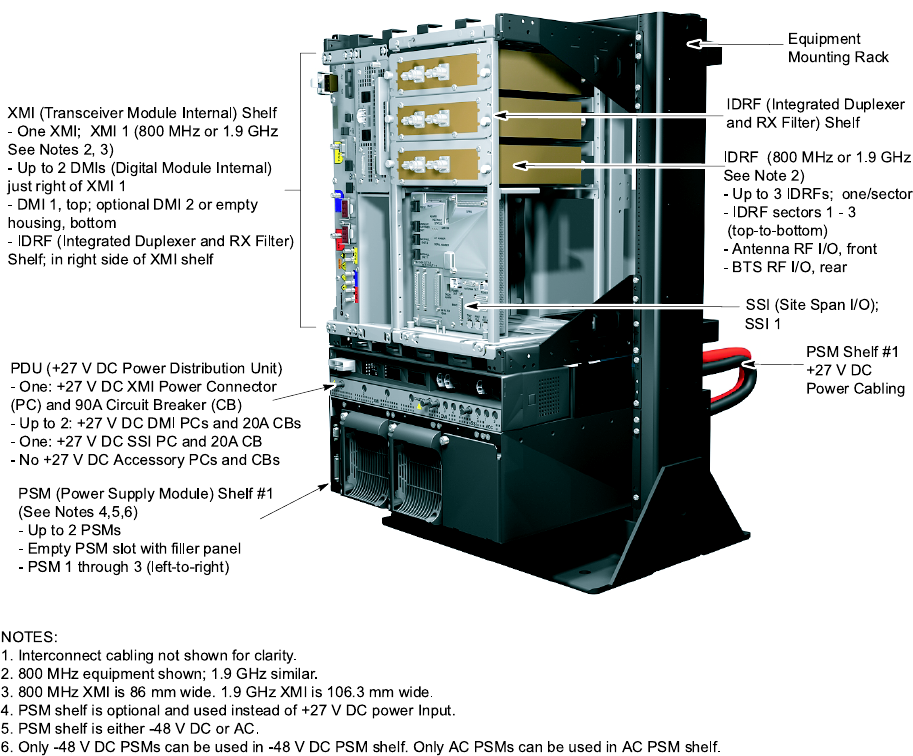
UBS Equipment Identication Chapter 1: Introduction
Figure 1 -2 UBS Macro Low Capacit y / Low Tier
ti-cdma-05993.eps
IDRF (Integ rate d Duplexer
an d RX F ilter) S he lf
SSI (Site Span I/O) ;
XMI (Transce iver Module Internal) Shel f
- One XMI; XMI 1 (80 0 MHz or 1.9 GH z
See N otes 2, 3)
- Up to 2 DMI s (Digital Module Interna l)
just right of XMI 1
- DMI 1, top; optional DMI 2 or empty
housing, bottom
- IDRF (Integ rated Dupl exer and RX Filter)
Shel f; in right sid e of X MI she lf
PDU (+27 V DC Po wer Distribution Unit)
- One : +27 V DC XMI P ower Connector
(PC) and 90A Circuit Breaker (C B)
- Up to 2: + 27 V DC DMI PC s an d 20A CBs
- One : +27 V DC S SI PC an d 20 A CB
- No +27 V DC Accesso ry P Cs and CBs
PSM (P ower Supply Module) Shelf #1
(See No tes 4,5,6 )
- Up to 2 PS Ms
- Empty PS M slot with filler pan el
- P SM 1 throug h 3 (left-to-right)
NOTES:
1. Intercon ne ct cab ling no t sho wn for clarit y.
2. 80 0 MHz eq uipme nt shown; 1.9 GH z similar.
3. 80 0 MHz XMI is 86 mm wide . 1.9 GH z XMI is 106.3 mm w ide.
4. PSM sh elf is optiona l and use d instea d o f +27 V DC power Input.
5. PSM sh elf is either - 48 V DC or AC.
6. Onl y -48 V DC PSMs can be u sed in -48 V DC PS M sh elf. Only AC PSMs can be us ed in AC P SM shelf.
PSM Shelf #1
+27 V DC
Power Cabling
Equipment
Mounting Rack
IDRF (800 MHz or 1.9 GHz
See Note 2)
- Up to 3 IDRFs; one/s ector
- IDRF sectors 1 - 3
(top-to-bottom)
- Ante nna RF I/O, front
- BTS RF I/O, rear
SSI 1
1 -18 68P09283A63 -5
FOA A UG 2007
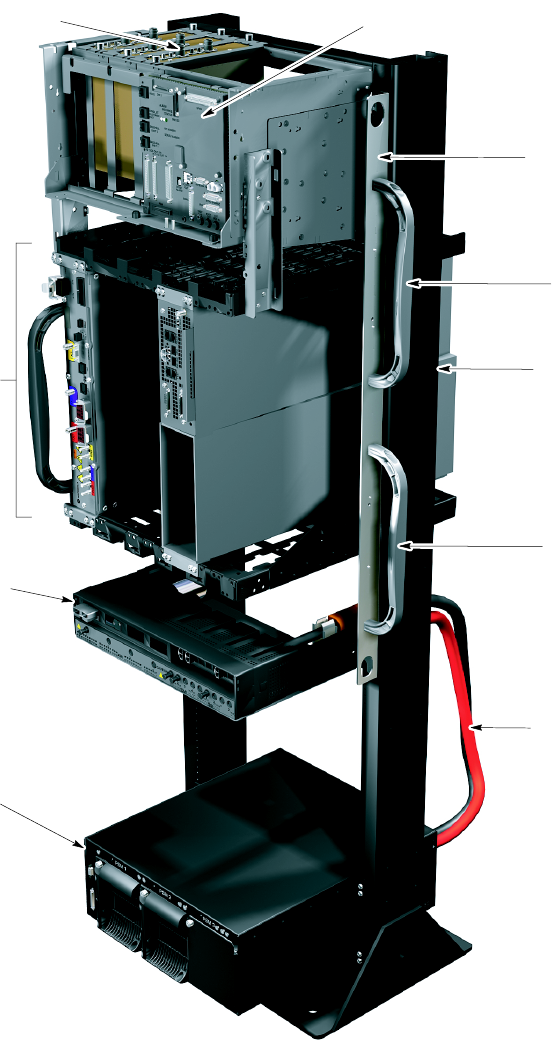
1X UBS Macro B T S Optimization/A TP UBS Equipment Identication
Figure 1 -3 Low Capacit y / High Tier
ti-cdma-05994.eps
IDRF (Integrated Duplexer and RX Filter) Shelf
- Up to 3 IDRFs (800 MHz or 1.9 GHz
See Note 2); one per sector
- IDRF sector 1 through sector 3 (left-to-right)
- Antenna RF I/O, top
- BTS RF I/O, bottom
SSI (Site Span I/O)
- One SSI; SSI 1
XMI (Transceiver Module Internal) Shelf
- One XMI; XMI 1 (800 MHz or 1.9 GHz
See Notes 2, 3) XMI shelf slot 1
- Up to 2 DMIs (Digital Module Internal)
XMI shelf slot 4
- DMI 1, top; optional DMI 2 or empty
housing, bottom
PDU (+27 VDC Power Distribution Unit)
See Note 8
- One: +27 VDC XMI Power Connector
(PC) and 90A Circuit Breaker (CB)
- Up to 2: +27 VDC DMI PCs and 20A CBs
- One: +27 VDC SSI PC and 20A CB
- No +27 VDC Accessory PCs and CBs
PSM (Power Supply Module) Shelf #1
(See Notes 4,5,6)
- Up to 3 PSMs
- Empty PSM slot with ller panel
- PSM 1 through 3 (left-to-right)
NOTES:
1. Interconnect cabling not shown for clarity.
2. 800 MHz equipment shown; 1.9 GHz similar.
3. 800 MHz XMI is 86 mm wide. 1.9 GHz XMI is 106.3 mm wide.
4. PSM shelf is optional and used instead of+27 VDC power Input.
5. PSM shelf is either -48 VDC or AC.
6. Only -48 VDC PSMs can be used in -48 VDC PSM shelf. Only AC PSMS can be used in AC PSM shelf.
7. Carrier strips are removable.
8. PDU may be moved down 6 rack units to ease future expansion.
PSM Shelf #1
+27 VDC Power
Cabling
Handle
Equipment
Mounting Rack
Handle
Carrier Strip with
Removable Lifting
Handles (one strip
on each side of rack)
See Note 7
68P09283A63 -5 1 -19
FOA A UG 2007
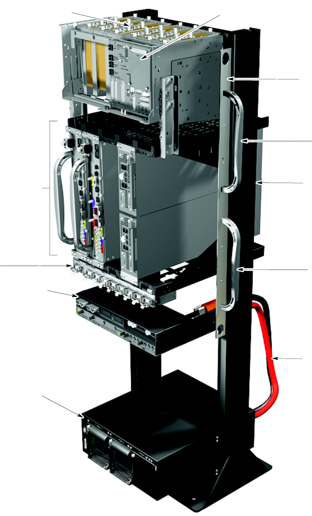
UBS Equipment Identication Chapter 1: Introduction
Figure 1 -4 Mid -Capacit y
ti-cdma-05995.eps
IDRF (Integrated Duplexer and RX Filter) Shelf
- Up to 6 IDRFs (800 MHz or 1.9 GHz
See Note 2); two sets of IDRFs,
each set with one IDRF per sector
- IDRF sector 1 through sector 3 (left-to-right)
- Antenna RF I/O, top
- BTS RF I/O, bottom
SSI (Site Span I/O)
- One SSI; SSI 1
XMI (Transceiver Module Internal) Shelf
- Two XMIs (800 MHz or 1.9 GHz
See Notes 2, 3); XMI 1, XMI 2 in
XMI shelf slots 1, 2
- Two DMIs (Digital Module Internal)
XMI shelf slot 4
- DMI 1, top; DMI 2, bottom
PDU (+27 VDC Power Distribution Unit)
See Note 8
- One: +27 VDC XMI Power Connector
(PC) and 90A Circuit Breaker (CB)
- Up to 2: +27 VDC DMI PCs and 20A CBs
- One: +27 VDC SSI PC and 20A CB
- No +27 VDC Accessory PCs and CBs
PSM (Power Supply Module) Shelf #1
(See Notes 4,5,6)
- Up to 3 PSMs
- Empty PSM slot with filler panel
- PSM 1 through 3 (left-to-right)
NOTES:
1. Interconnect cabling not shown for clarity.
2. 800 MHz equipment shown; 1.9 GHz similar.
3. 800 MHz XMI is 86 mm wide. 1.9 GHz XMI is 106.3 mm wide.
4. PSM shelf is optional and used instead of+27 VDC power Input.
5. PSM shelf is either -48 VDC or AC.
6. Only -48 VDC PSMs can be used in -48 VDC PSM shelf. Only AC PSMS can be used in AC PSM shelf.
7. Carrier strips are removable.
8. PDU may be moved down 6 rack units to ease future expansion.
PSM Shelf #1
+27 VDC Power
Cabling
Handle
Equipment
Mounting Rack
Handle
Carrier Strip with
Removable Lifting
Handles (one strip
on each side of rack)
See Note 7
RX Splitter
1 -20 68P09283A63 -5
FOA A UG 2007