Nokia Solutions and Networks T5GX1 UBS CDMA XMI Transceiver at 800 MHz User Manual Exhibit 123b
Nokia Solutions and Networks UBS CDMA XMI Transceiver at 800 MHz Exhibit 123b
Contents
Exhibit 123b
1X UBS Macro B T S Optimization/A TP UBS Equipment Identication
UBS Component Identication
The UBS is comprised of the following modules (see Figure 1 -2 ):
•P ower Distribution Unit (PDU)
•DMI (Digital Module Internal)
•XMI (Transceiver Module Internal)
•S SI (Site Span I/O)
•IDRF (Integrated Duplexers & RF Filters)
•CRMS (Cellular Remote Monitoring System)
•External GPS (Optional)
•QHSO (Optional)
68P09283A63 -5 1 -21
FOA A UG 2007
UBS Equipment Identication Chapter 1: Introduction
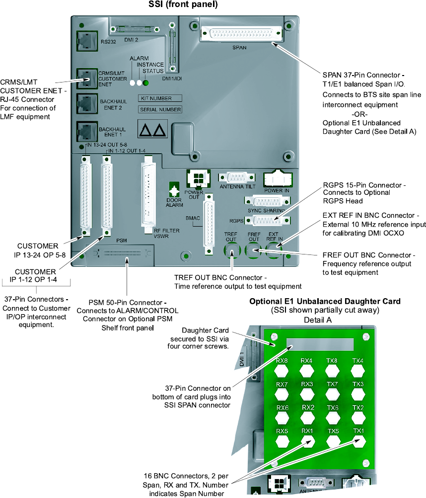
Figure 1 -5 UBS Site Span I/O P anel
SSI (fron t p anel)
CUST OMER
IP 13-24 OP 5-8
CUST OMER
IP 1-12 OP 1-4
37-Pin Conne ctors -
Con nect to Customer
IP/OP interconnect
equipment.
PSM 50 -Pin Conne ctor -
Con nects to ALARM/CONTROL
Con nector on Optional PSM
Shelf front pa ne l
RGPS 15 -P in Connector -
Con nects to O ptional
RGPS He a d
SPAN 37-Pin Connector -
T1/E1 ba lance d Span I/O.
Con nects to BTS s ite span line
interconnect equipment
-OR-
Optional E1 Unbalanced
Dau ghter Ca rd (S ee Detail A)
De tail A
Optional E1 Unbalanced Da ughter Card
(SSI shown partially cut away)
Dau ghter Card
secured to SS I via
four corne r sc rews.
37-Pin Conne ctor on
bottom of c ard p lugs into
SSI SPAN connector
16 BNC Con nectors, 2 pe r
Span, RX and TX. Number
indicates Span Number
ti-cdma-05698.eps
TREF OUT BNC Con nector -
Time reference output to te st eq uipme nt
FREF O UT BNC Connector -
Freq ue ncy reference output
to te st equipment
EXT REF IN BNC Con ne ctor -
External 10 MHz re fere nce input
for ca libra ting DMI OCXO
CRMS /LMT
CUST OMER ENE T -
RJ-45 Con nector
For conne ction of
LMF equip me nt
1 -22 68P09283A63 -5
FOA A UG 2007
1X UBS Macro B T S Optimization/A TP UBS Equipment Identication
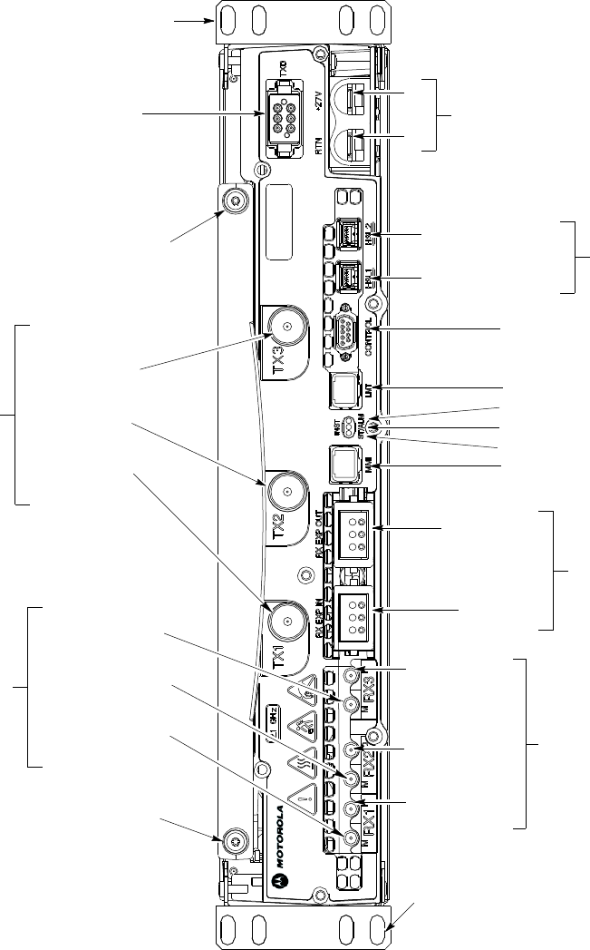
Figure 1 -6 XMI Front P anel
ti-cdma-06106.eps
Mounting
RX EXP IN
RX EXP OUT
TOP
MMI
(RJ45)
CONTROL( 9-pin D-type)
To/From TX Combiner; Future Use
LMT (RJ45)
ALM (Alarm) LED
STA (Status) LED
RX Expansion Ports
(ganged mini-coaxial)
To/From RX Splitter
TXD (ganged MCX-type)
To/From TX Combiner; Future Use
(For proper XMI TX RF Outputs operation,
the TXD port must be terminated with
TXD Attenuator, Motorola part number
5888774T01, if XMI is not cabled to
TX Combiner)
(+)
(-)
+27V DC Input Power
From PDU
HSL2; to/from DMI-2
(HSSDC2 Type)
HSL1; to/from DMI-1
RX DIV
(QMA-Type Coaxial)
Always used on XMI 2;
Only used on XMI 1 if
XMI 2 is not equipped
RX 1; from
Sector 1 IDRF
RX 2; from
Sector 2 IDRF
RX 3; from
Sector 3 IDRF
RX MAIN
(QMA-Type Coaxial)
Always used on XMI 1;
Never used on XMI 2
RX 1; from Sector
1 IDRF
RX 2; from Sector
2 IDRF
RX 3; from Sector
3 IDRF
TX-3; to
Sector 3 IDRF
TX-1; to
Sector 1 IDRF
Handle Mounting
Screw Hole
Handle Mounting
Screw Hole
TX RF Outputs
NOTE:
1. Equipment shown is typical. The
actual equipment appearance may
vary slightly.
(QN-type coaxial)
Mounting Tab
BOTTOM
INST (Instance) LED
2. The debug ports are intended to be used
primarily for testing or debugging purposes
by Motorola.
These ports may be used in the field for
maintenance purposes by customers.
T
ab
or RX Cross-connect
cable
TX-2; to
Sector 2 IDRF
68P09283A63 -5 1 -23
FOA A UG 2007
UBS Equipment Identication Chapter 1: Introduction
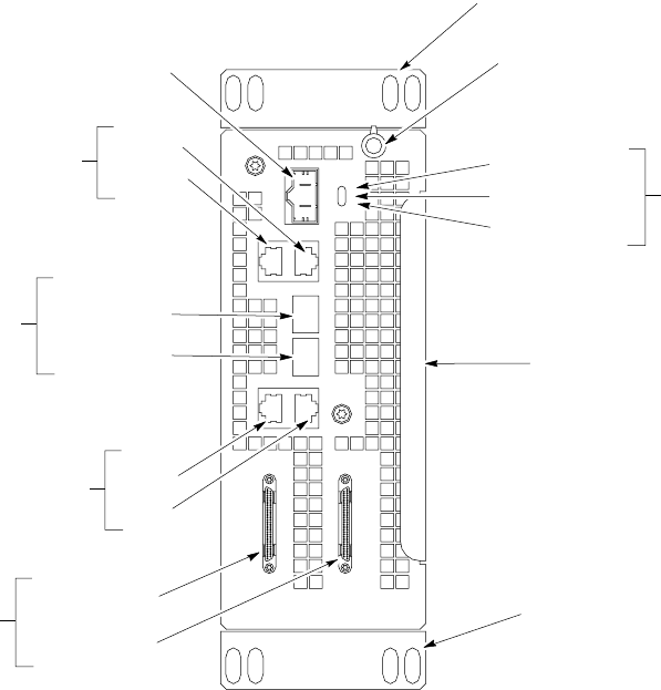
Figure 1 -7 DMI Front P anel
LMT
IDI/SSI1
SSI2
TEST XMI1/DC XMI2 RS232-2
RS232-1
+27VDC
INST
ST ALM
ti-cdma-06111.eps
Mounting Tab
TOP 1/4-T urn Fastener
(Retains DMI Chassis
to DMI Cage)
MMI Serial Debug
Ports (RJ45)
Note 2
+27 V DC Input
Power From PDU
(mini-Molex)
Ethernet 10/100 BaseT
Debug Ports (RJ45)
Note 2
LMT
TEST
Serial Backhaul;
Traffic & Control Data
(VHDCI Typel)
To/From SSI-1
To/From SSI-2
Mounting Tab
NOTES:
1. Equipment shown is typical. The actual equipment appearance may vary slightly.
2. The debug ports are intended to be used primarily for testing or debugging purposes by Motorola.
These ports may be used in the field for maintenance purposes by customers. Carefully follow written
procedures when using these ports in the field. Failure to do so could result in an inoperable FRU.
BOTTOM
Handle
To/From XMI-2
To/From XMI-1
LEDs
ST (Status)
ALM (Disk Alarm)
INST (Instance)
CPRI 1.2288 Gbps serial data
links (SFP Type). Carries XMI
baseband I & Q data
as well as control data
RS232-2
RS232-1
1 -24 68P09283A63 -5
FOA A UG 2007

C h a p t e r
2
Preliminary Operations■■■■■■■■■■■■■■■■■■■■■■■■■■■■■■■■■■■■■■■■■■■■■■■■■■■■■■■■■■■■■■
■
■
■
■
68P09283A63 -5 2 -1
A UG 2007 FOA

Introduction Chapter 2: Preliminary Oper ations
Introduction
■■■■■■■■■■■■■■■■■■■■■■■■■■■■■■■■■■■■■■■■■■■■■■■■■■■■■■■■■■■■■■
■
■
This section first verifies proper frame equipage.
Cell Site Types
Sites are configured as omni, 2–sector or 3–sector with a maximum of two carriers. F or more
information on the differences in site types, please refer to the 1X UBS Macro BTS Hardware
Installation manual.
NEC Files
The Network Element Configuration (NEC) files contains site type and equipage data
information and passes it directly to the LMF during optimization. The number of sector -carriers
and carrier frequency assignments are two of the equipage data included in the NEC files.
Be sure that the correct NECB–<version information>–bts#.xml and NECJ–<version
information>–bts#.xml les are used for the specic UBS site. These should be the
NEC les that are pro vided for the UBS b y the OMC –R. Code v ersion of the UBS should
be synched with the code in the OMC -R before lea ving the site. F ailure to use the
correct NEC les can cause system errors. F ailure to use the correct NEC les to log
into a site can cause incorrect calibr ation information to be gener ated.
Site Equipage Verication
Review the site documentation. Match the site engineering equipage data to the UBS and
optional equipment installed at the site. Physically inspect and verify the equipment provided
for the UBS .
Alw a ys wear a conductiv e, high impedance wrist str ap while handling an y circuit
card/module to prev ent damage b y ESD . After remo v al, the card/module should be
placed on a conductiv e surface or back into the anti–static shipping container .
2 -2 68P09283A63 -5
FOA A UG 2007

1X UBS Macro B T S Optimization/A TP Pre -P owerup T ests
Pre -Powerup Tests■■■■■■■■■■■■■■■■■■■■■■■■■■■■■■■■■■■■■■■■■■■■■■■■■■■■■■■■■■■■■■
■
■
Objective
This procedure checks for any electrical short circuits and verifies the operation and tolerances
of the cell site and UBS power supply units prior to applying power for the first time.
Test Equipment
The following test equipment is required to complete the pre–power–up tests:
•Digital Multimeter (DMM)
Alw a ys wear a conductiv e, high impedance wrist str ap while handling an y circuit
card/module to prev ent damage b y Electrostatic Discharge (ESD).
Cabling Inspection
Using the site -specific documentation generated by Motorola Systems Engineering, verify that
the following cable systems are properly installed according to the 1X UBS Macro Installation
manual:
•Receive RF cabling
•Transmit RF cabling
•GPS cabling to E -GPS (GPS RF cable or RGPS cable from the RGPS antenna (if the EGPS
option is not used))
DC Power Pre -Test
Before applying any power to the UBS , follow the procedure in Procedure 2 -1 to verify there are
no shorts in the UBS DC distribution system.
68P09283A63 -5 2 -3
FOA A UG 2007
Pre -P owerup T ests Chapter 2: Preliminary Oper ations
Procedure 2 -1 DC P ower Pre–test (UBS)
When handling circuit boards and modules, be sure to wear a
grounding strap to prevent damages caused by Electrostatic
Discharge (ESD).
1
V erify that unit is a DC powered unit.
Physically verify
that all DC power sources supplying
power to the UBS are OFF or disengaged.
2
Ensure that all available circuit breakers on PDU are disengaged (pulled out).
3
V erify that DC power cable is properly connected.
4
Enable power at the source. Use a DMM to verify that the power to the UBS
is within specification.
2 -4 68P09283A63 -5
FOA A UG 2007

1X UBS Macro B T S Optimization/A TP Initial P ower -up T ests
Initial Power -up Tests■■■■■■■■■■■■■■■■■■■■■■■■■■■■■■■■■■■■■■■■■■■■■■■■■■■■■■■■■■■■■■
■
■
Power -up Procedures
P otentially lethal v oltage and current lev els are routed to the UBS equipment. This
test must be performed with a second person present, acting in a safet y role. R emo v e
all rings, jewelry , and wrist w atches prior to beginning this test.
DC Input Power
In the tests to follow , before applying any power , verify the correct power feed and return cables
are connected between the power supply breakers and the power connectors of the UBS .
P ower will first be verified at the input to each UBS . A fter power is verified, modules within
the UBS itself will be powered up and verified one at a time.
Motorola recommends that the DC input power cable used to connect the UBS to the main DC
power source conforms to the guidelines outlined in
1X UBS Macro BTS Hardware Installation –
68P09283A62.
Common Power Supply Verication
P erform Procedure 2 -2 on any UBS connected to the common power supply at the site after the
common power supply has been installed and verified per the power supply OEM suggested
procedures.
Mak e sure the connector adapters are securely attached to each of the UBS power
feeds and returns. Also , mak e sure the cables ha v e been properly installed into each
connector . Loose power cables ma y cause a re.
Continued
68P09283A63 -5 2 -5
FOA A UG 2007

Initial P ower -up T ests Chapter 2: Preliminary Oper ations
Procedure 2 -2 Procedure for Common P ower Supply V erication
1
Physically verify
that all DC power sources supplying the UBS are OFF or
disengaged.
2
V isually inspect input cables, verify correct input power polarity . (Cables
should be marked.)
3
Engage all available circuit breakers on PDU .
4
A fter power is applied to the UBS , use a DMM to verify power supply output
voltages are within specifications.
Initial Power -up (Frame)
This procedure must be performed on each frame after input power from the common power
supply has been verified. F ollow the procedure in Procedure 2 -3 to apply initial power to the
frame itself , verifying that it is operating within specification.
Procedure 2 -3 Procedure for Initial P ower –up (Fr ame)
1
V erify that power cable is properly connected.
Set UBS power switch to ON .
2
Use a DMM to verify power supply output voltage remains within nominal
specifications: +27V (
nominal
).
2 -6 68P09283A63 -5
FOA A UG 2007

C h a p t e r
3
LMF Operation
■■■■■■■■■■■■■■■■■■■■■■■■■■■■■■■■■■■■■■■■■■■■■■■■■■■■■■■■■■■■■■
■
■
■
■
68P09283A63 -5 3 -1
A UG 2007 FOA

Optimization/Calibr ation Introduction Chapter 3: LMF Oper ation
Optimization/Calibration Introduction■■■■■■■■■■■■■■■■■■■■■■■■■■■■■■■■■■■■■■■■■■■■■■■■■■■■■■■■■■■■■■
■
■
Introduction
This section describes for using the Line Maintenance F acility (LMF) to verify the proper
operation of the installed UBS system. T est setup and calibration are provided in support of
the installation verification and optimization.
Before using the W inLMF , use an editor to view the
CA VEA TS
section in the
readme.html
file in the c:\wlmf folder for any applicable information.
3 -2 68P09283A63 -5
FOA A UG 2007
1X UBS Macro B T S Optimization/A TP Preparing the LMF
Preparing the LMF■■■■■■■■■■■■■■■■■■■■■■■■■■■■■■■■■■■■■■■■■■■■■■■■■■■■■■■■■■■■■■
■
■
Overview
Before optimization can be performed, the LMF application software must be installed
and configured on a computer platform meeting Motorola -specified requirements (see
Recommended T est Equipment and Software in Chapter 1 Introduction ).
Software and files for installation and updating of the LMF are provided on CD ROM disks. The
following installation items must be available:
•LMF Program on CD ROM
The following section provides information and instructions for installing and updating the
LMF software and files.
WinLMF File Structure Overview
The W inLMF uses a
<x>:\lmf home directory>
folder that contains all of the essential data
for installing and maintaining the UBS . The following list outlines the folder structure for LMF .
Except for the UBS -# folders, these folders are created as part of the LMF installation. Refer to
the
CDMA LMF Operator’s Guide
for a complete description of the folder structure.
68P09283A63 -5 3 -3
FOA A UG 2007
Preparing the LMF Chapter 3: LMF Oper ation
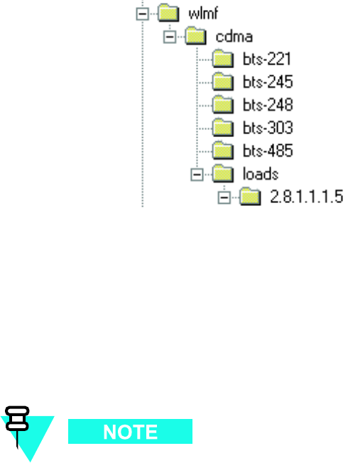
Figure 3 -1 LMF F older Structure
ti-cdma-05823.eps
The
loads
folder and all the folders below it are no longer contained on the LMF
CD as of LMF 2.9.0.0. When installing LMF software on a system that has never
contained LMF software before, the user will need to create these folders manually .
When installing a new version of LMF onto a PC already containing LMF software,
any existing folders will be unaffected.
WinLMF Directory
The CDMA LMF installation program creates the default home directory , c:\wlmf , and installs the
application files and subdirectories (folders) in it. Because this can be changed at installation,
the CDMA LMF home directory will be referred to with the generic convention of:
<x>:\lmf home directory>
Where:
<x> = the LMF computer drive letter where the CDMA LMF home directory is located.
<lmf home directory> = the directory path or name where the CDMA LMF is installed.
3 -4 68P09283A63 -5
FOA A UG 2007
1X UBS Macro B T S Optimization/A TP Preparing the LMF
WinLMF Operating System Installation
This section provides information and instructions for installing and updating the LMF software
and files.
First Time Installation Sequence:
1. Install Java Runtime Environment (JRE)
2. Install U/WIN K -shell emulator (optional)
3. Install LMF application programs
Any time U/WIN is re -installed, the LMF application software must also be
re -installed. This is because the LMF application installation modifies some of
the files that are installed during the U/W in installation. These modifications are
necessary for proper LMF CLI operation.
If required, a separate CD ROM of UBS Binaries may be obtained for binary updates.
First Time Installation Sequence
F ollow the procedure in Procedure 3 -1 to install the LMF application program using the LMF
CD ROM.
Procedure 3 -1 CD ROM Installation
1
Insert the LMF Program CD ROM into the LMF CD ROM drive.
•If the Setup screen appears, follow the instructions displayed on the
screen.
•If the Setup screen is not displayed, proceed to step 2 .
2
Click on the Start button.
3
Select Run .
4
Enter d:\autorun in the Open box and click OK .
If applicable, replace the letter dwith the correct CD ROM drive
letter .
68P09283A63 -5 3 -5
FOA A UG 2007
LMF to UBS Connection Chapter 3: LMF Oper ation
LMF to UBS Connection■■■■■■■■■■■■■■■■■■■■■■■■■■■■■■■■■■■■■■■■■■■■■■■■■■■■■■■■■■■■■■
■
■
LMF to UBS Connection
F ollow the procedure in Procedure 3 -2 to establish LMF to UBS connection.
Procedure 3 -2 LMF to UBS Connection Procedure
1
V erify that the W inLMF computer has an Ethernet port.
2
V erify that a serial port (normally COM 1) is available for use.
3
Connect CDMA LMF to the UBS via the CRMS/LMT Customer ENET or DMI
LMT port.
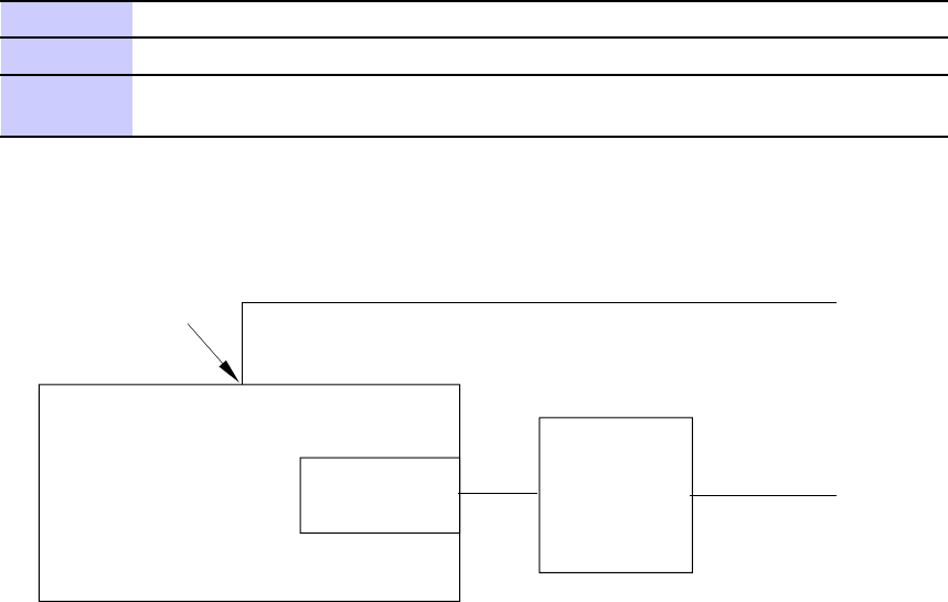
Figure 3 -2 LMF Connection Detail
ti-cdma-05842-A.eps
COM1
Connector
LMF NOTEBOOK Ethernet Port Ethernet
Hub To CRMS / LMT
To GPIB Box
RS-232 Null Modem Cable
CUSTOMER ENET Port
The Ethernet hub is is used when the Ethernet interface on the LMF PC
may not be able to keep a reliable ethernet link.
NOTE:
or DMI LMT Port
(if CRMS is in use)
3 -6 68P09283A63 -5
FOA A UG 2007

1X UBS Macro B T S Optimization/A TP Using WinLMF
Using WinLMF
■■■■■■■■■■■■■■■■■■■■■■■■■■■■■■■■■■■■■■■■■■■■■■■■■■■■■■■■■■■■■■
■
■
Basic WinLMF Operation
LMF Coverage in This Publication — All references to the LMF in this publication are for the
CDMA application program
Operating Environments — The LMF application program allows the user to work in the two
following operating environments which are accessed using the specified desktop icons:
•Graphical User Interface (GUI) using the W inLMF with UBS Support icon
•Command Line Interface (CLI) using the W inLMF CLI UBS icon
CLI can be run if the GUI is already running.
Basic Operation — The GUI is the primary optimization and acceptance testing operating
environment. The CLI environment provides additional capability to the user to perform
manually controlled acceptance tests and audit the results of optimization and calibration
actions. Both operations allow the following:
•Selecting and deselecting UBS devices
•Unlocking devices
•Locking devices
•Resetting devices
•Obtaining device status
The following additional basic operation can be performed in a GUI environment:
•Sorting a status report window
•Displaying the Electronic Identification (EID) information of the FRUs
F or detailed information on performing these and other LMF operations, refer to the LMF
On -Line Help.
Unless otherwise noted
, LMF procedures in this manual are performed using the
GUI environment.
68P09283A63 -5 3 -7
FOA A UG 2007
Using WinLMF Chapter 3: LMF Oper ation
Online Help - T ask oriented online help is available in the LMF by clicking on Help from the
menu bar .
The LMF Display and the UBS
UBS Display - When the LMF is logged into a UBS , a frame tab is displayed. The frame tab will be
labeled with
Frame
, the UBS number , a dash, and the frame number (for example, Frame -812 -1
for UBS 812, RFMF 1). There is only one frame for the UBS , so there will only be one tab.
Graphical User Interface Overview
The LMF uses a Graphical User Interface (GUI), which supports the following functions:
•Selecting a device or devices
•Selecting an action to apply to selected device(s)
•Status report window displaying progress of actions taking place and related information
•Notification when an action is complete and related information such as indication of
success or failure
•An OK button to close the status report window .
Understanding GUI Operation
F or detailed information on GUI operation and the LMF , refer to the
LMF Help function on -line
documentation
.
Command Line Interface Overview
The LMF also provides Command Line Interface (CLI) capability . Activate the CLI by clicking on
a shortcut icon on the desktop. The CLI can only be launched while the GUI is running.
If the CLI tool was
NOT
installed, it is possible to telnet to the CLI without
the UWIN tool by using the command line in windows ( RUN-> cmd ) and typing
in the window after the LMF has already logged in: telnet localhost 9600
appset newline value=2
3 -8 68P09283A63 -5
FOA A UG 2007

1X UBS Macro B T S Optimization/A TP Using WinLMF
CLI Format Conventions
The CLI command can be broken down in the following way:
•verb
•device including device identifier parameters
•switch
•option parameters
keywords
equal signs
parameter values
Spaces are required between the verb, device, switch, and option parameters. A hyphen is re-
quired between the device and its identifiers. The following is an example of a UBS CLI command:
configure sc -<bts#> -<sector#> -<carrier#> pgain=<pgain#>
mdm_slot=<mdm_slot#> ce=<ce#> [pnoffset=<pnoffset#>]
Refer to the
W inLMF CDMA CLI Commands – 68P09275A12
manual for further information
on CLI commands and their use.
Logging into a UBS
Logging into a UBS establishes a communications link between the UBS and the LMF . An LMF
session can be logged into only one UBS at a time.
Prerequisites
Before attempting to login to a UBS , ensure the following have been completed:
•The LMF is properly connected to the UBS (see Figure 3 -2 )
•The LMF application program is correctly installed and prepared
•Preparing the LMF for Connectivity and Configuring the Controller of UBS procedures
are completed
•The LMF computer was connected to the UBS before starting the W indows operating
system and LMF software. If necessary , restart the computer after connecting it to the
UBS in accordance with Procedure 3 -3 and Figure 3 -2 .
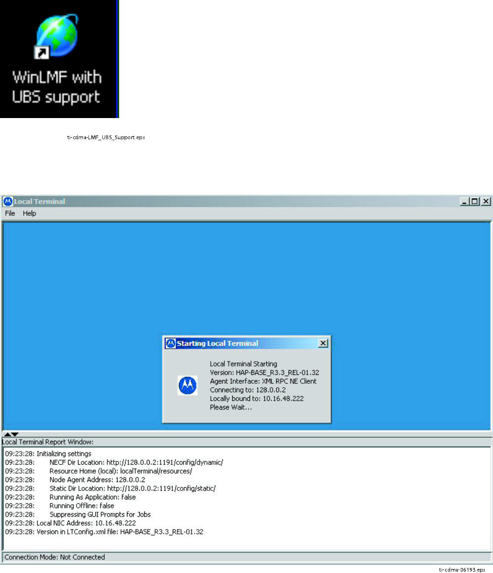
•When the PC has completed startup, click on WinLMF with UBS Support icon Figure 3 -3
to bring up the Local T erminal window ( Figure 3 -4 )
•IP Address is 128.0.0.xxx
•Netmask address is 255.255.255.128
•BlackICE or other similar process is disabled
•W indow
Internet Connection Firewall
and other firewall programs should be disabled
•Java Runtime Environment (JRE) is installed and version matched
68P09283A63 -5 3 -9
FOA A UG 2007
Using WinLMF Chapter 3: LMF Oper ation
Figure 3 -3 WinLMF Icon
ti-cdma-LMF_UBS_Support.eps
Figure 3 -4 Local T erminal (Login Screen)
ti-cdma-06193.eps
3 -10 68P09283A63 -5
FOA A UG 2007
1X UBS Macro B T S Optimization/A TP Using WinLMF
UBS Login from the GUI Environment
F ollow the procedure in Procedure 3 -3 to log into a UBS when using the GUI environment.
Procedure 3 -3 UBS GUI Login Procedure
The LMF computer Network Interface Card (NIC) IP
address is set to 128.0.0.48, subnetmask 255.255.255.128.
Ping UBS fr ame (128.0.0.2) from PC (128.0.0.48)
Disable/Stop all rew alls and other applications (e.g.
BlackICE) which ma y block UDP / T CP tr ansfers.
Disable all activ e F TP serv ers running on the PC.
T erminate process called inetd.exe if it is running.
NO TE: inetd32.exe ma y be activ e and doesn’ t require termination
1
Start the CDMA LMF GUI environment by double clicking on the W inLMF
with UBS Support desktop icon (if the LMF is not running). See Figure 3-4
F or the first connection the user may be prompted about FTP
server localization on PC and choose the Ethernet adapter .
2
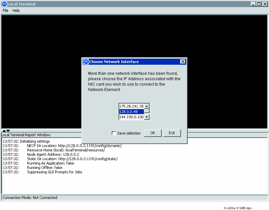
A
Choose Network Interface
window will appear asking for IP Address of the
Network Interface Card (NIC) of the element under test. See Figure 3-5 .
3
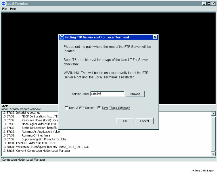
A
Setting FTP Server root for Local T erminal
window
will appear to asking for the path to the root directory .
F or the typical LMF installation, the default Server Root path is C:\wlmf .
See Figure 3-6 .
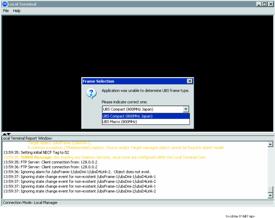
4
A
Frame Selection
window will appear asking for type of UBS under test.
See Figure 3-7
5
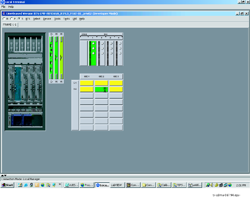
A window similar to Figure 3-8 should appear .
6
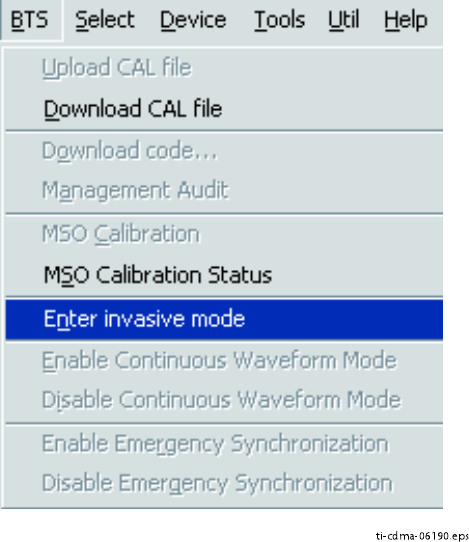
Click on BTS . A drop down menu appears.
Select Enter invasive mode . See Figure 3-9
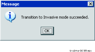
7
A message window appears stating that invasive mode is successful. See
Figure 3-10 .
68P09283A63 -5 3 -11
FOA A UG 2007
Using WinLMF Chapter 3: LMF Oper ation
Figure 3 -5 Network Interface Selection
ti-cdma-01683.eps-
3 -12 68P09283A63 -5
FOA A UG 2007
1X UBS Macro B T S Optimization/A TP Using WinLMF
Figure 3 -6 F TP Serv er
ti-cdma-06188.eps-
68P09283A63 -5 3 -13
FOA A UG 2007
Using WinLMF Chapter 3: LMF Oper ation
Figure 3 -7 Fr ame Selection
ti-cdma-01687.eps-
3 -14 68P09283A63 -5
FOA A UG 2007
1X UBS Macro B T S Optimization/A TP Using WinLMF
Figure 3 -8 Local T erminal GUI
ti-cdma-06194.eps-
68P09283A63 -5 3 -15
FOA A UG 2007
Using WinLMF Chapter 3: LMF Oper ation
Figure 3 -9 In v asiv e Mode Selection
ti-cdma-06190.eps
3 -16 68P09283A63 -5
FOA A UG 2007
1X UBS Macro B T S Optimization/A TP Using WinLMF
Figure 3 -10 In v asiv e Mode Message Window
ti-cdma-06189.eps
68P09283A63 -5 3 -17
FOA A UG 2007
Using WinLMF Chapter 3: LMF Oper ation
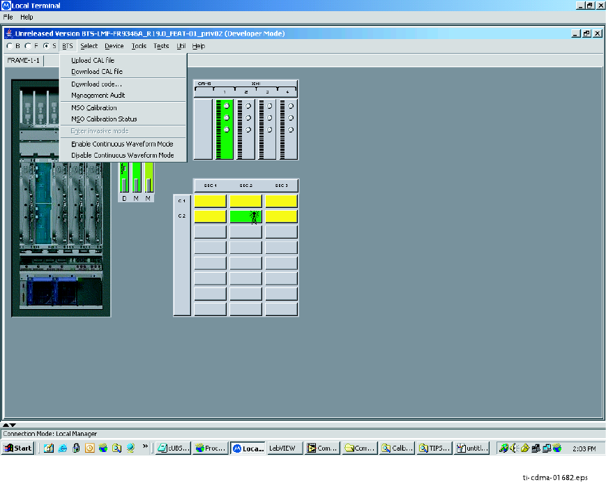
LMF Menus and Options
The following figures display the menus and options available to the user .
Figure 3 -11 displays the selections available under the BTS menu.
Figure 3 -11 B T S Menu
ti-cdma-01682.eps
3 -18 68P09283A63 -5
FOA A UG 2007
1X UBS Macro B T S Optimization/A TP Using WinLMF
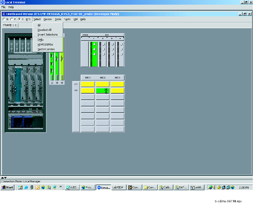
Figure 3 -12 displays the choices that can be selected for testing.
Figure 3 -12 Select Menu
ti-cdma-06198.eps
68P09283A63 -5 3 -19
FOA A UG 2007
Using WinLMF Chapter 3: LMF Oper ation
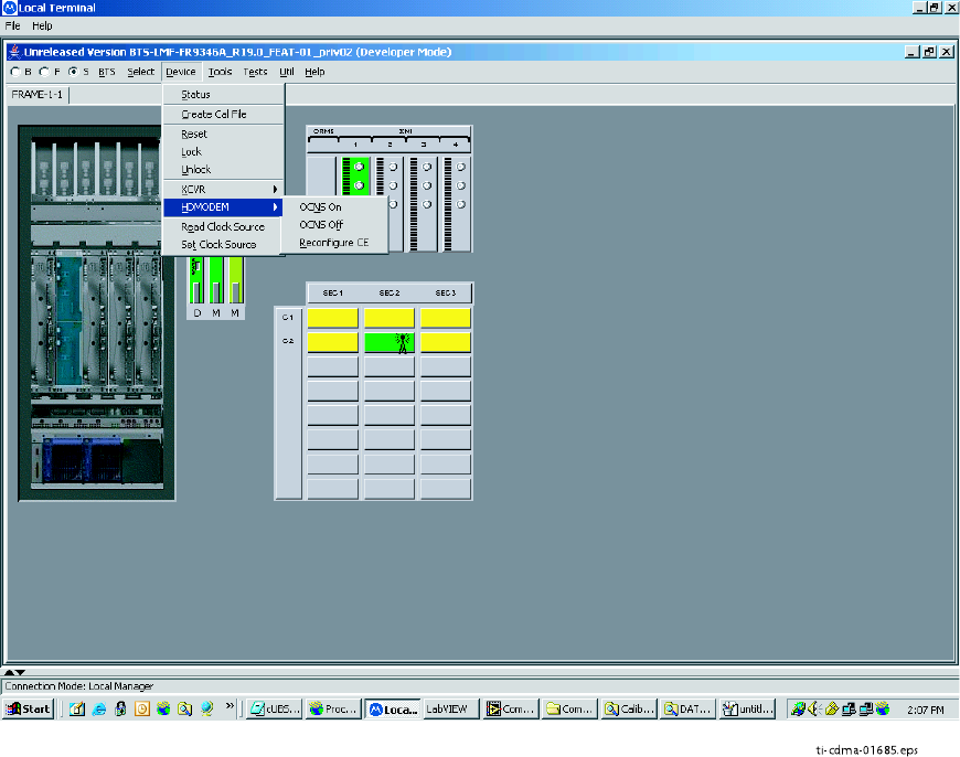
Figure 3 -13 displays the actions for the DMI.
Figure 3 -13 Device Menu - DMI (HDModem)
ti-cdma-01685.eps
3 -20 68P09283A63 -5
FOA A UG 2007
1X UBS Macro B T S Optimization/A TP Using WinLMF
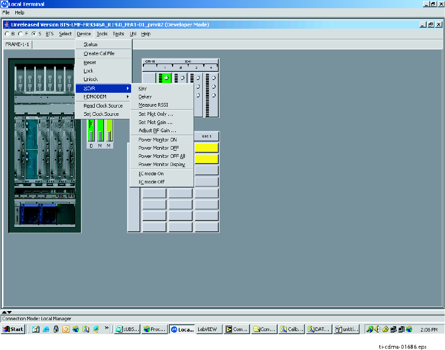
Figure 3 -14 displays the actions for the XMI.
Figure 3 -14 Device Menu - XMI
ti-cdma-01686.eps
68P09283A63 -5 3 -21
FOA A UG 2007
Using WinLMF Chapter 3: LMF Oper ation
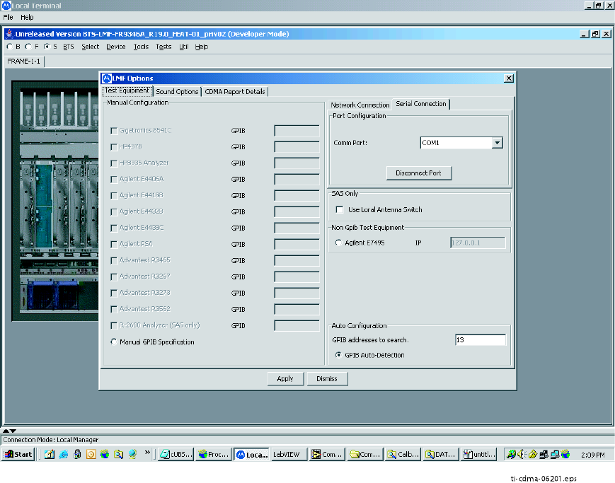
Figure 3 -15 displays the choices for the manually configuring equipment.
Figure 3 -15 T ools Menu - Options
ti-cdma-06201.eps
3 -22 68P09283A63 -5
FOA A UG 2007
1X UBS Macro B T S Optimization/A TP Using WinLMF
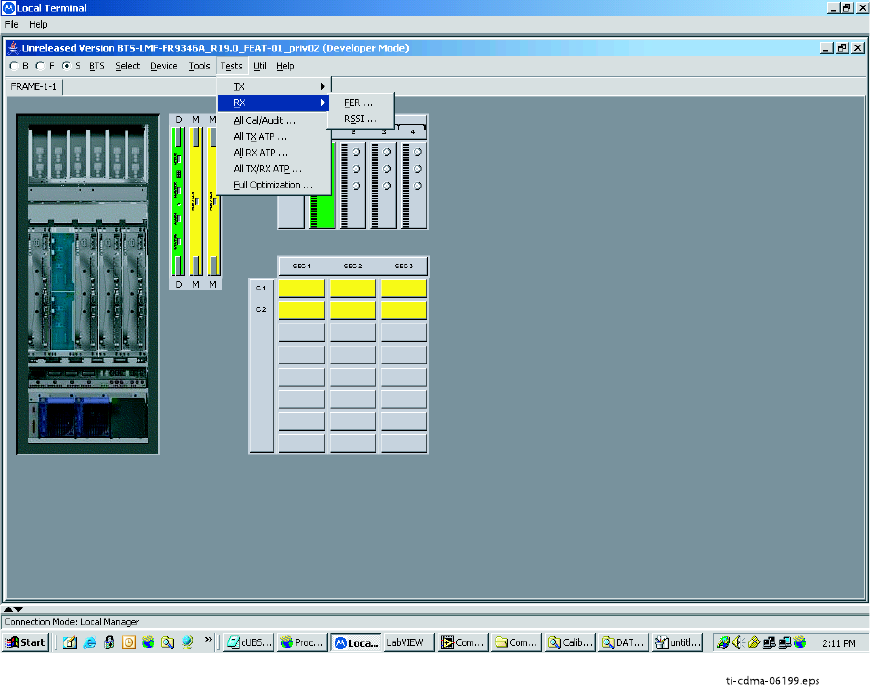
Figure 3 -16 displays the receive tests for the UBS .
Figure 3 -16 T ests Menu - RX
ti-cdma-06199.eps
68P09283A63 -5 3 -23
FOA A UG 2007
Using WinLMF Chapter 3: LMF Oper ation
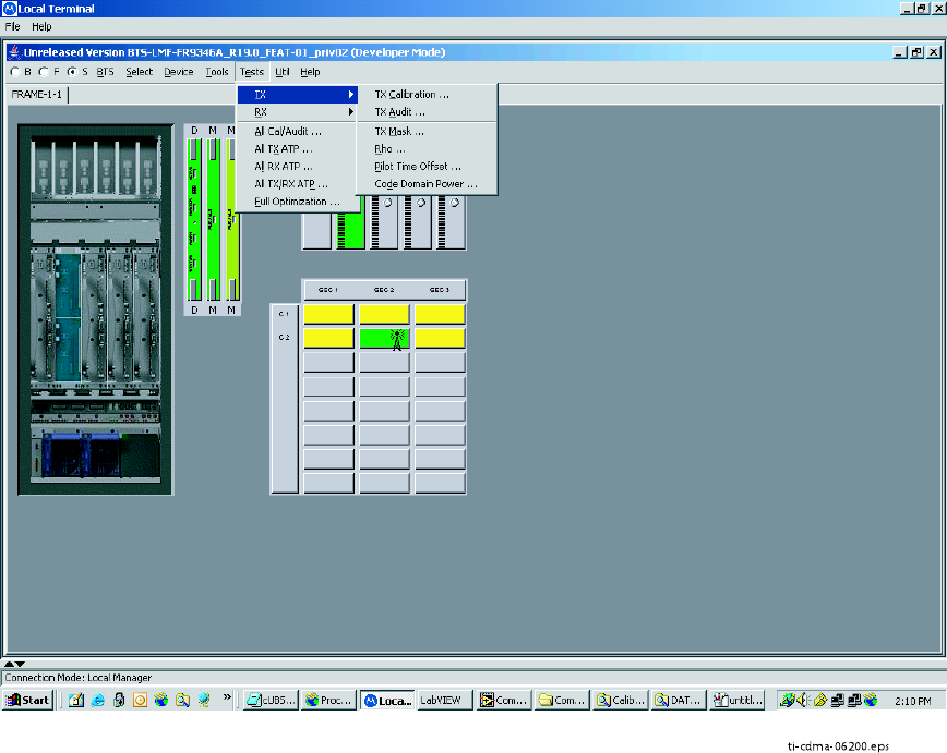
Figure 3 -17 displays the transmit tests for the UBS .
Figure 3 -17 T ests Menu - TX
t
i-cdma-06200.eps
3 -24 68P09283A63 -5
FOA A UG 2007
1X UBS Macro B T S Optimization/A TP Using WinLMF
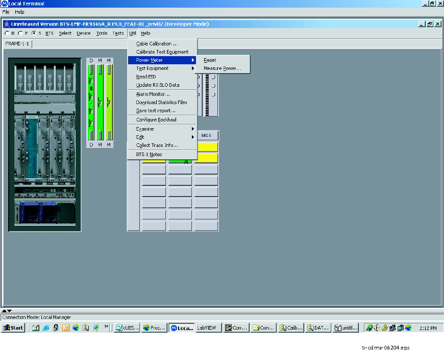
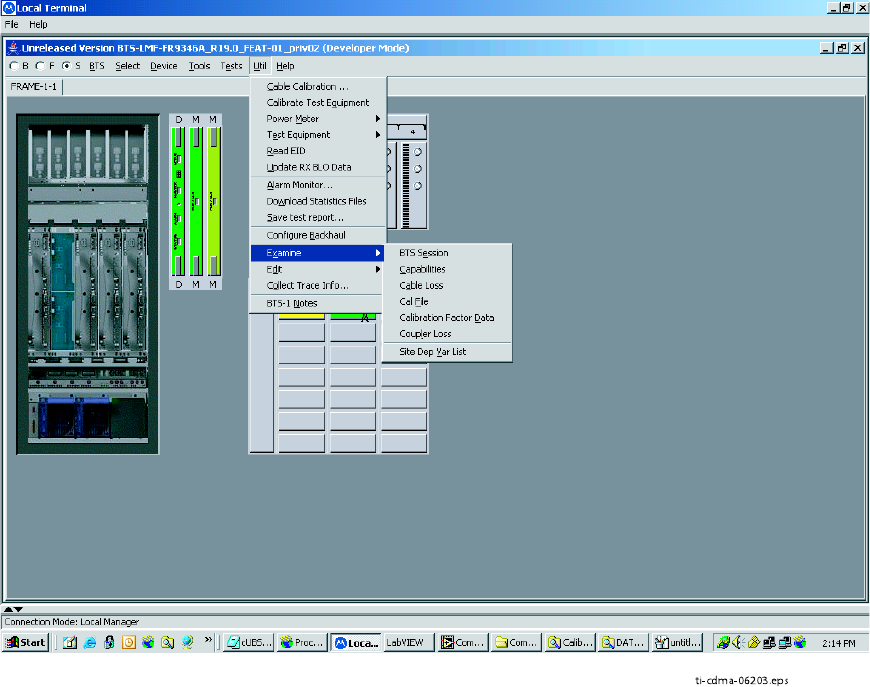
Figure 3 -18 through Figure 3 -21 display the various UTIL menu choices that allow analysis of
the UBS under test.
Figure 3 -18 Util Menu - P ower Meter
ti-cdma-06204.eps
68P09283A63 -5 3 -25
FOA A UG 2007
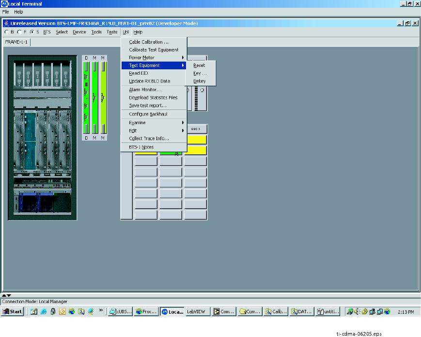
Using WinLMF Chapter 3: LMF Oper ation
Figure 3 -19 Util Menu - T est Equipment
ti-cdma-06205.eps
3 -26 68P09283A63 -5
FOA A UG 2007
1X UBS Macro B T S Optimization/A TP Using WinLMF
Figure 3 -20 Util Menu - Examine
ti-cdma-06203.eps
68P09283A63 -5 3 -27
FOA A UG 2007
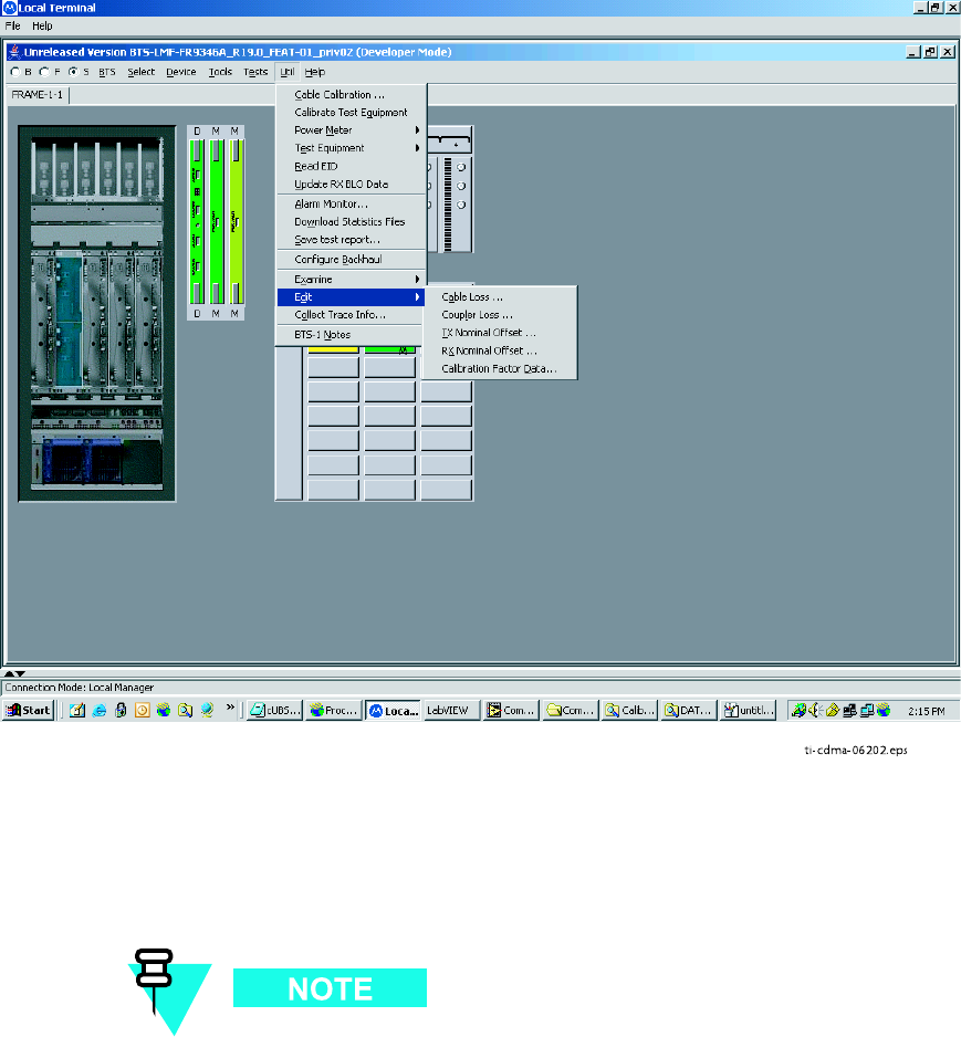
Using WinLMF Chapter 3: LMF Oper ation
Figure 3 -21 Util Menu - Edit
ti-cdma-06202.eps
Logging Out
Logging out of a UBS can only be accomplished from the Graphical User Interface (GUI) mode.
The GUI and CLI environments use the same connection to a UBS . If a GUI and the
CLI session are running for the same UBS at the same time, logging out of the UBS
environment will log out of it for both.
3 -28 68P09283A63 -5
FOA A UG 2007
1X UBS Macro B T S Optimization/A TP Using WinLMF
Logging Out of a UBS from the GUI Environment
F ollow the procedure in Procedure 3 -4 to logout of a UBS when using the GUI environment.
Procedure 3 -4 UBS GUI Logout Procedure
1
Click on File on the Local T erminal menu bar .
2
Click the Exit item in the pull-down menu.
UBS will perform a soft reset.
Anytime the LMF is exited from the UBS , the DMI controller(s)
will automatically reboot within 1 minute in order to clear out any
test configurations and boot up under the original configuration in
the NECB and NECJ files.
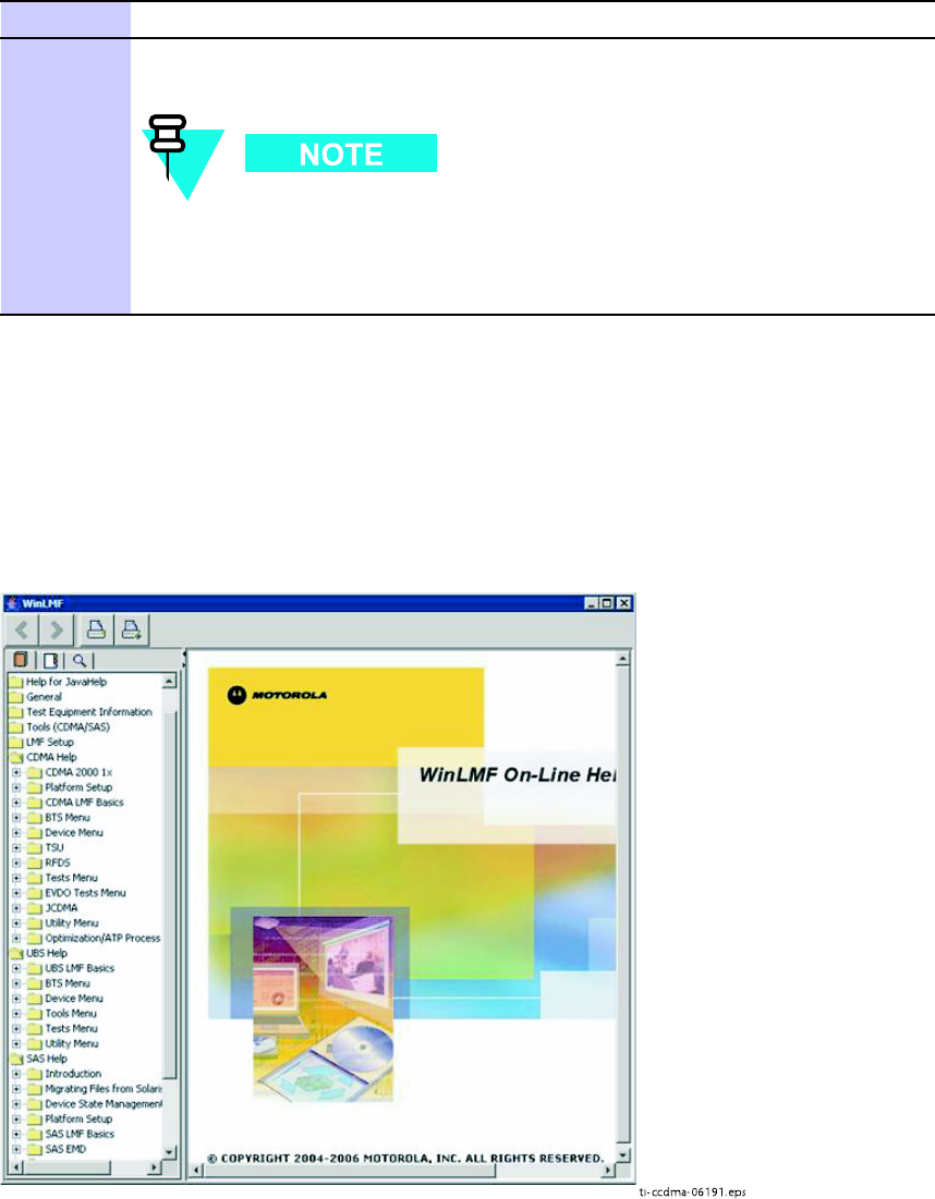
On -Line Help
T ask oriented on -line help is available in the LMF by clicking on Help in the window menu bar ,
and selecting LMF Help from the pull–down menu.
Figure 3 -22 Help Screen
ti-ccdma-06191.eps
68P09283A63 -5 3 -29
FOA A UG 2007

Download Code to UBS Chapter 3: LMF Oper ation
Download Code to UBS■■■■■■■■■■■■■■■■■■■■■■■■■■■■■■■■■■■■■■■■■■■■■■■■■■■■■■■■■■■■■■
■
■
The process of downloading code to a UBS consists of two principal steps:
1. Code transfer to the UBS followed by distribution to the devices
2. Code activation
Normally , the OMC -R will download code to the UBS through the span line once the UBS is
configured to establish communication with the OMC -R. However , there may be some occasions
that the LMF may be used to download load instead, such as at a staging location used to
pre -load replacement DMIs with same code load version required by OMC -R. Then, when the
new DMI is taken to the site, it will integrate and synchronize much faster with the OMC -R.
When the code is activated, the UBS will re–start, and the LMF will lose contact with the UBS .
It will be necessary to log into the UBS again after the UBS devices complete initialization
with the new code.
Prerequisites
The following must be accomplished before downloading code:
•A
bts–#
folder has been created for the UBS in the cdma subdirectory of the LMF home
directory . (Refer to W inLMF File Structure Overview on page 3 - 3 )
•The current
NECB -<software_release#>—bts#.xm
l and
NECJ -<software_re-
lease#>—bts#.xml
files for the UBS are saved in the UBS
bts–#
folder
•The LIF .xml file and code and data binary files for the software release are saved in the
cdma\loads\
<software_release#>
subdirectory folder of the LMF home directory , where
<software_release#>
is the number of the software release installed on the BS S . The
<software_release#> should be the same as defined in the NECB/NECJ files
•The LMF is logged into the UBS in invasive mode
If W inZip is used to unzip codeload, please be sure to uncheck the CR/LF conversion
on the W inZip tool: From W inZip window , select Options -> Configuration ->
Miscellaneous and unchecked T AR file smart CR/LF conversion box.
Download Procedure
Code files are downloaded to the UBS using an FTP server . The user is given a choice of using
the built–in LMF FTP server or an external FTP server . F or initial download of a UBS , the built–in
FTP server in the LMF should be used. This procedure covers using the LMF built–in FTP server .
3 -30 68P09283A63 -5
FOA A UG 2007
1X UBS Macro B T S Optimization/A TP Download Code to UBS
The UBS code load should always be synchronized with the download from the
OMC -R before leaving the UBS site. Refer to Reset All Devices and Initialize Site
Remotely on page 5 - 8 for the procedure to do this.
Procedure 3 -5 Download Code
1
In the menu bar of the Local T erminal BTS window , select BTS > Download Code...
2
If prompted that the “F ollowing operation may overwrite NECB, NECJ , LIF , and calibration
files on the BTS”, click Y es .
3
In the dialog box which appears, if the Use Local FTP server checkbox is not checked, click
in it to select this option.
Result: A check mark will appear in the box.
4
In field labeled Software version enter the <software_release#> as specified in the
prerequisite section (for example, 2.19.0.0.20).
5
If a “clean download” is required (download every file, even if they are the same as those
currently installed on the UBS), click in the P erform clean load checkbox.
Result: A check mark will appear in the box.
6
Click Ok to start the download.
Code download can require up to 40 minutes to complete.
7
When the download is complete, click Ok to close the status report window .
When the code load is complete, the UBS will re–start, and the LMF will lose
contact with the UBS .
8
Log the LMF into the UBS again.
68P09283A63 -5 3 -31
FOA A UG 2007
T est Equipment Set Up Chapter 3: LMF Oper ation
Test Equipment Set Up■■■■■■■■■■■■■■■■■■■■■■■■■■■■■■■■■■■■■■■■■■■■■■■■■■■■■■■■■■■■■■
■
■
Connecting Test Equipment to the UBS
The following equipment is required to perform optimization:
•LMF
•Communications system analyzer model supported by the LMF
•Non -radiating transmit line termination load
•Directional coupler and in -line attenuator
•RF cables and connectors
•Null modem cable (see Figure 1 -1 )
•GPIB interface box
The following figures provide representative illustrations of connections for test equipment
currently supported by the LMF :
•Figure 3 -23 ,Figure 3 -24 ,Figure 3 -25 , and Figure 3 -26 show the test set connections
for TX calibration.
•Figure 3 -27 ,Figure 3 -28 ,Figure 3 -29 , and Figure 3 -30 show test set connections for
optimization/A TP tests.
•Figure 3 -31 ,Figure 3 -32 ,Figure 3 -33 , or Figure 3 -34 illustrate cable calibration test set–up.
Test Equipment GPIB Address Settings
All test equipment except the Agilent E7495A and
Anritsu
MT8212B is controlled by the LMF
through an IEEE -488/GPIB bus. T o communicate on the bus, each piece of test equipment must
have a GPIB address set which the LMF will recognize. The standard address settings used by
the LMF for the various types of test equipment items are as follows:
•Signal generator address: 1
•P ower meter address: 13
•Communications system analyzer: 18
Using the procedures included in the Setting GPIB Addresses section of Appendix D T est
Equipment Preparation , verify and, if necessary , change the GPIB address of each piece of test
equipment used to match the above.
3 -32 68P09283A63 -5
FOA A UG 2007

1X UBS Macro B T S Optimization/A TP T est Equipment Set Up
Supported Test Equipment
Optimization and A TP testing for CDMA2000 1X sites or carriers may be performed using the
following test equipment:
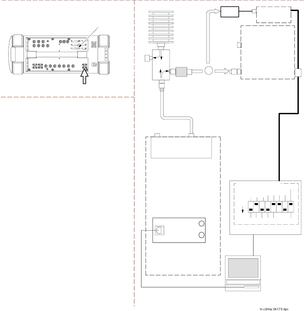
•Advantest R3267 Analyzer with Advantest R3562 Signal Generator
•Agilent E4406A with E4432B Signal Generator
•Agilent 8935 series E6380A communications test set (formerly HP 8935) with option 200
or R2K and with E4432B signal generator for 1X FER
•Agilent E7495A or Agilent E7495B communications test sets
The E4406A/E4432B pair , or the R3267/R3562 pair , should be connected together using a GPIB
cable. In addition, the R3562 and R3267 should be connected with a serial cable from the Serial
I/O to the Serial I/O . This test equipment is capable of performing tests in both IS -95 A/B mode
and CDMA 2000 mode if the required options are installed.
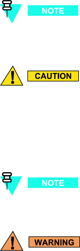
T o prev ent damage to the test equipment, all TX test connections must be through the
directional coupler and in -line attenuator as shown in the test setup illustr ations.
Optional test equipment
A spectrum analyzer , such as the HP8594E, and a signal generator supporting the required
frequency ranges can be used to perform manual cable calibration.
68P09283A63 -5 3 -33
FOA A UG 2007
T est Equipment Set Up Chapter 3: LMF Oper ation
Test Equipment Preparation
See Appendix D T est Equipment Preparation for specific steps to prepare each type of test
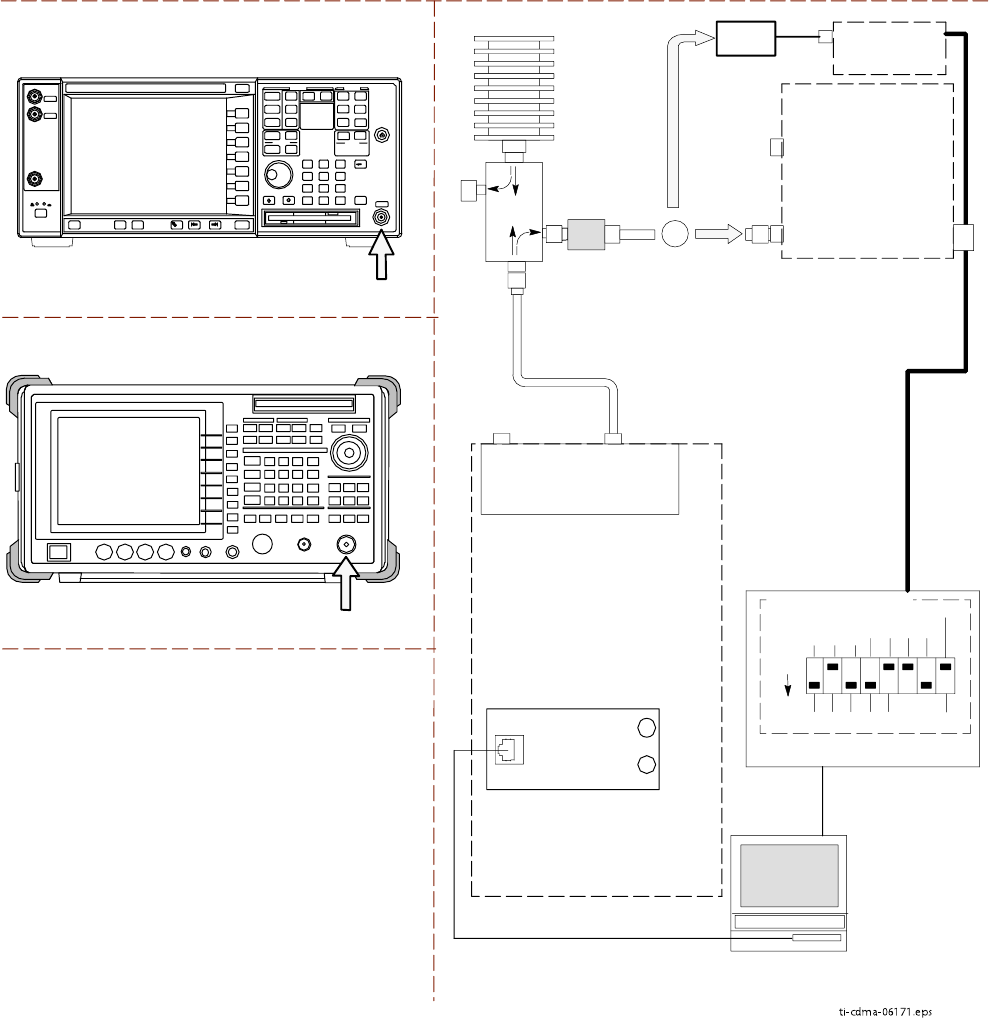
set and power meter to perform calibration and A TP . The Agilent E7495A communications
test set requires additional setup and preparation. This is described in detail in Appendix D
T est Equipment Preparation .
Calibration of the communications test set (or equivalent test equipment) must be
performed at the site before calibrating the overall test equipment set. Calibrate the
communications test set after it has been allowed to warm up and stabilize for a
minimum of 60 minutes
.
If an y piece of the test equipment set (for example, test cable, RF adapter) has
been replaced, the test equipment set must be re–calibr ated. F ailure to do so could
introduce measurement errors, resulting in incorrect measurements and degr adation
to system performance.
Equipment Warm -up
W arm -up UBS equipment for a
minimum of 60 minutes
prior to performing the UBS optimization
procedure. This assures UBS site stability and contributes to optimization accuracy .
Time spent running initial power -up, hardware/firmware audit, and UBS download
counts as warm -up time.
Before connecting an y test equipment directly to an y UBS TX or duplex ed TX/RX
connector (for example, the TX/RX M connectors for a UBS equipped with IDRFs),
v erif y there are NO channels k ey ed. A t activ e sites, ha v e the OMC –R place the carriers
assigned to the XMI under test OOS . F ailure to do so can result in serious personal
injury and/or equipment damage.
3 -34 68P09283A63 -5
FOA A UG 2007
1X UBS Macro B T S Optimization/A TP T est Equipment Set Up
Automatic Cable Calibration
Refer to Calibrate T est Cabling using Communications System Analyzer on page 3 - 64 for
automatic cable calibration procedures using a communications test set.
Manual Cable Calibration
If manual cable calibration is required, refer to Calibrate T est Cabling Using Signal Generator &
Spectrum Analyzer on page 3 - 69 for procedures to use a spectrum analyzer and signal generator .
Set -up for TX Calibration
Figure 3 -23 ,Figure 3 -24 ,Figure 3 -25 , and Figure 3 -26 show test set connections for TX
calibration.
68P09283A63 -5 3 -35
FOA A UG 2007
T est Equipment Set Up Chapter 3: LMF Oper ation
Figure 3 -23 TX Calibr ation T est Setup – Agilent 8935
ti-cdma-06170.eps
AGILENT 8935 SERIES E6380A (FORMERLY HP 8935)
TEST SETS TRANSMIT (TX) SET UP
RF IN/OUT
HP-IB
TO GPIB
BOX
RS232-GPIB
INTERFACE BOX
GPIB
CABLE
COMMUNICATIONS
TEST SET
CONTROL
IEEE 488
GPIB BUS
UNSHIELDED TWISTED
PAIR (UTP) CABLE
(RJ45 CONNECTORS)
RS232
NULL
MODEM
CABLE
OUT
S MODE
DATA FORMAT
BAUD RATE
GPIB ADRS
G MODE
ON
TEST SET
INPUT/
OUTPUT
PORTS
100-WATT (MIN)
NON-RADIATING
RF LOAD
IN
CDMA
LMF
DIP SWITCH SETTINGS
TX TEST
CABLE
POWER
METER
(OPTIONAL)*
ADVANTEST MODEL R3465
INPUT
50-OHM
GPIB
CONNECTS TO
BACK OF UNIT
* A POWER METER CAN BE
USED IN PLACE OF THE
COMMUNICATIONS TEST SET
FOR TX CALIBRATION/AUDIT
POWER
SENSOR
10 DB MINIMUM
IN-LINE ATTENUATOR
INTERNAL OR PCMCIA ETHERNET
NETWORK INTERFACE CARD (NIC)
50 Ω
TERM.
30 DB
DIRECTIONAL
COUPLER
OR
TX TEST
CABLE
TX TEST
CABLE
UBS
CRMS/LMT
CUSTOMER
ENET
FREF
OUT
TREF
OUT
SSI
RX DIVTX/RX M
(DUPLEXED TX
AND RX)
IDRF
3 -36 68P09283A63 -5
FOA A UG 2007
1X UBS Macro B T S Optimization/A TP T est Equipment Set Up
Figure 3 -24 TX Calibr ation T est Setup – Agilent E4406A and Adv antest R3267
ti-cdma-06171.eps
TEST SETS TRANSMIT (TX) SET UP
RS232-GPIB
INTERFACE BOX
GPIB
CABLE
COMMUNICATIONS
TEST SET
CONTROL
IEEE 488
GPIB BUS
UNSHIELDED TWISTED
PAIR (UTP) CABLE
(RJ45 CONNECTORS)
RS232
NULL
MODEM
CABLE
OUT
S MODE
DATA FORMAT
BAUD RATE
GPIB ADRS
G MODE
ON
TEST SET
INPUT/
OUTPUT
PORTS
100-W ATT (MIN)
NON-RADIA TING
RF LOAD
IN
TX TEST
CABLE
CDMA
LMF
DIP SWITCH SETTINGS
POWER
METER
(OPTIONAL)*
* A POWER METER CAN BE
USED IN PLACE OF THE
COMMUNICATIONS TEST SET
FOR TX CALIBRATION/AUDIT
POWER
SENSOR
RF IN
INTERNAL OR PCMCIA ETHERNET
NETWORK INTERFACE CARD (NIC)
50 Ω
TERM.
30 DB
DIRECTIONAL
COUPLER
ADVANTEST MODEL R3267
AGILENT E4406A
RF INPUT
50 Ω
1O DB MINIMUM
IN-LINE ATTENUATOR
TX TEST
CABLE
TX TEST
CABLE
OR
UBS
CRMS/LMT
CUSTOMER
ENET
FREF
OUT
TREF
OUT
SSI
RX DIV TX/RX M
(DUPLEXED TX
AND RX)
IDRF
68P09283A63 -5 3 -37
FOA A UG 2007
T est Equipment Set Up Chapter 3: LMF Oper ation
Figure 3 -25 TX Calibr ation T est Setup – Agilent E7495A
ti-cdma-06172.eps
TEST SETS TRANSMIT (TX) SET UP
CDMA
LMF
50 Ω
TERM.
TX TEST
CABLE
30 DB
DIRECTIONAL
COUPLER
100-W ATT (MIN.)
NON-RADIA TING
RF LOAD
POWER
SENSOR
1O DB MINIMUM
IN-LINE ATTENUATOR
ETHERNET HUB
UNSHIELDED TWISTED PAIR (UTP)
CABLE (RJ45 CONNECTORS)
AGILENT E7495A
PORT 2
RF IN
SYNC MONITOR
EVEN SEC TICK
PULSE REFERENCE
FROM SSI TREF OUT
Use only
Agilent supplied
power adapter
GPS
GPIO
Serial 1
Serial 2
Power REF
50 MHz
Sensor
Ext Ref
In
Even Second
Sync In
Antenna
Port 1
RF Out / SWR
Port 2
RF In
INTERNAL
ETHERNET
CARD
COMMUNICATIONS
SYSTEM ANALYZER
POWER METER
PORT 2
RF IN
PORT 1
RF OUT
INTERNAL OR PCMCIA ETHERNET
NETWORK INTERFACE CARD (NIC)
OR
TX TEST
CABLE
TX TEST
CABLE
NOTES:
1. WHEN USING THE E7495A, TX TESTS
REQUIRE A MINIMUM OF 30 DB
ATTENUATION PLUS THE CABLE
LOSSES.
2. IF BTS IS EQUIPPED WITH DRDCS
(DUPLEXED RX/TX SIGNALS), CONNECT
THE TX TEST CABLE TO THE DRDC
ANTENNA CONNECTOR.
UBS
CRMS/LMT
CUSTOMER
ENET
FREF
OUT
TREF
OUT
SSI
RX DIV TX/RX M
(DUPLEXED TX
AND RX)
IDRF
3 -38 68P09283A63 -5
FOA A UG 2007