Nokia Solutions and Networks T5GX1 UBS CDMA XMI Transceiver at 800 MHz User Manual Exhibit 123c
Nokia Solutions and Networks UBS CDMA XMI Transceiver at 800 MHz Exhibit 123c
Contents
Exhibit 123c
1X UBS Macro B T S Optimization/A TP T est Equipment Set Up
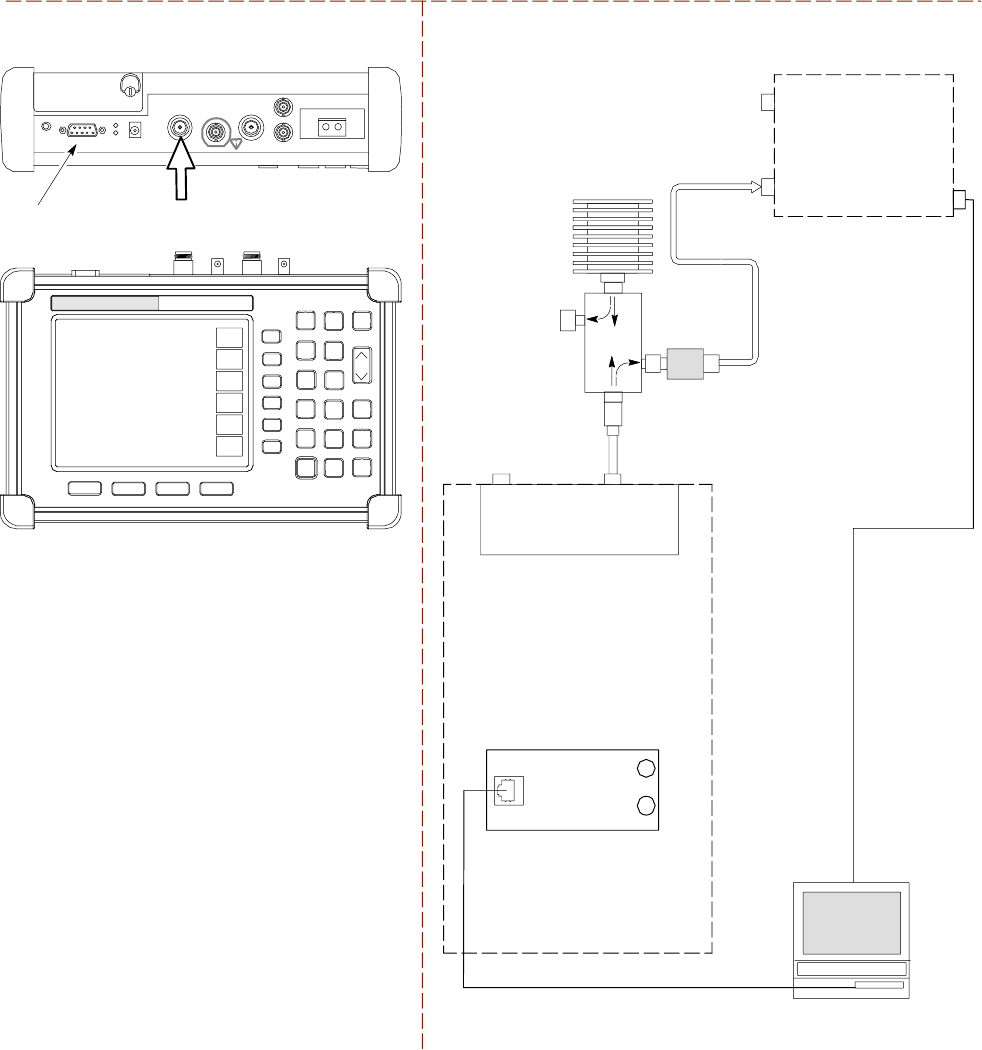
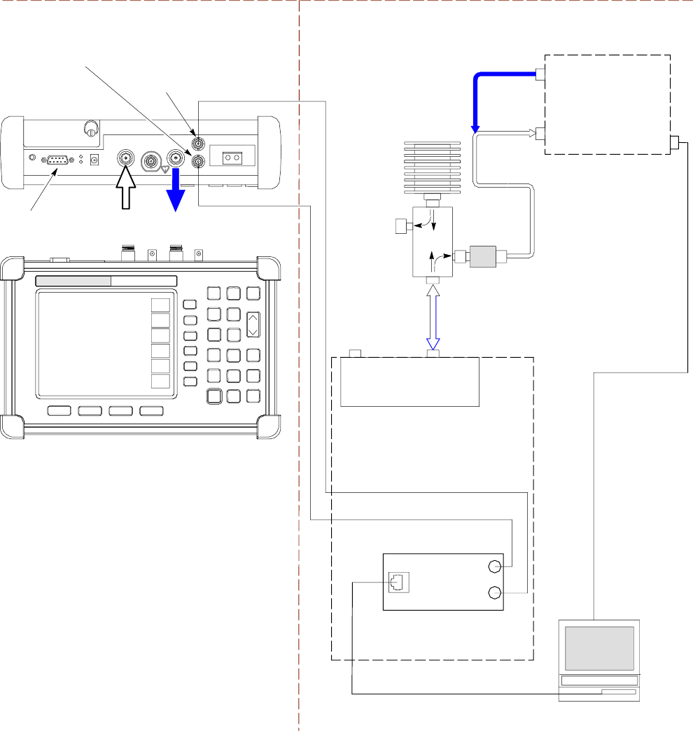
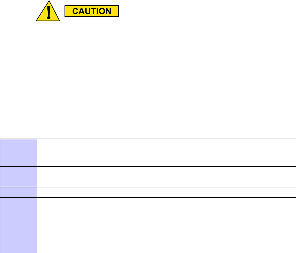
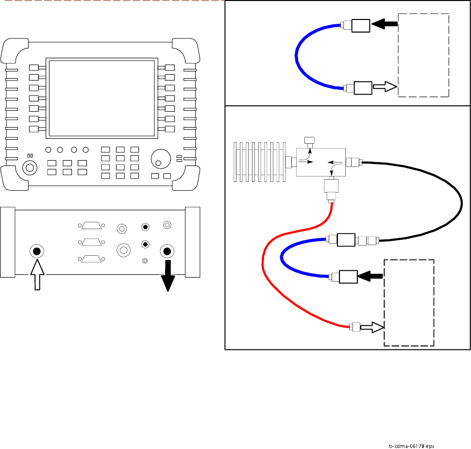
Figure 3 -26 TX Calibr ation T est Setup – Anritsu MT8212B
TEST SETS TRANSMIT (TX) SET UP
CDMA
LMF
50 Ω
TERM.
TX AND
RX TEST
CABLE
30 DB
DIRECTIONAL
COUPLER
100-W ATT (MIN.)
NON-RADIA TING
RF LOAD
1O DB MINIMUM
IN-LINE ATTENUATOR
INTERNAL OR PCMCIA ETHERNET
NETWORK INTERFACE CARD (NIC)
UNSHIELDED TWISTED PAIR (UTP)
CABLE (RJ45 CONNECTORS)
SERIAL
INTERFACE
COMMUNICATIONS
SYSTEM ANALYZER
RF IN
50 Ω
RF OUT
50 Ω
RF IN
50 Ω
ANRITSU MT8212B
TX AND
RX TEST
CABLE
RS232 SERIAL
INTERFACE CABLE
SERIAL
INTERFACE
CONNECTOR
UBS
CRMS/LMT
CUSTOMER
ENET
FREF
OUT
TREF
OUT
SSI
RX DIV TX/RX M
(DUPLEXED TX
AND RX)
IDRF
tti-cdma-06206.eps
68P09283A63 -5 3 -39
FOA A UG 2007
T est Equipment Set Up Chapter 3: LMF Oper ation
Setup for ATP
Figure 3 -27 ,Figure 3 -28 ,Figure 3 -29 , and Figure 3 -30 show test set connections for A TP tests.
3 -40 68P09283A63 -5
FOA A UG 2007
1X UBS Macro B T S Optimization/A TP T est Equipment Set Up
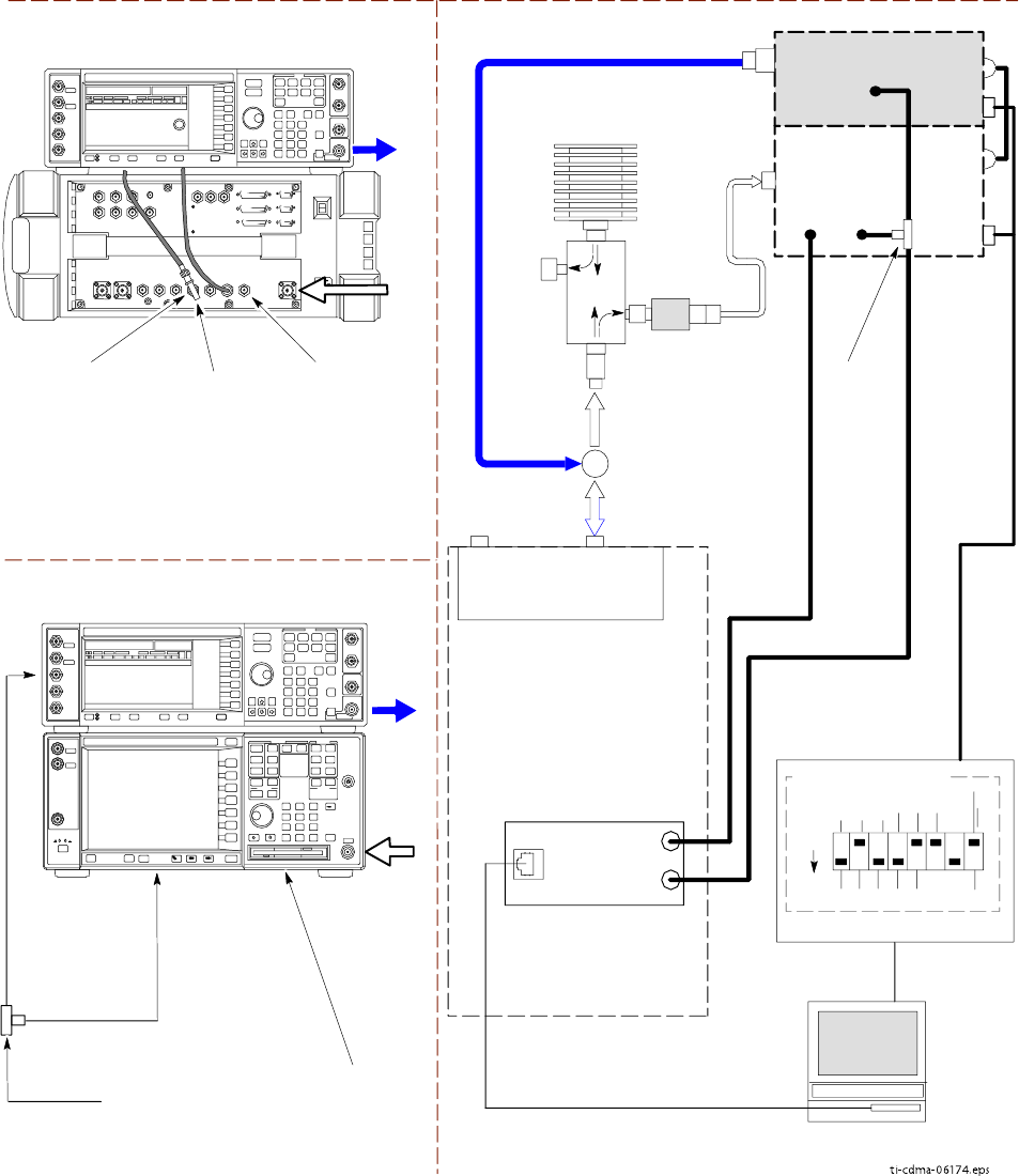
Figure 3 -27 A TP T est Setup – Agilent E4432B/8935 and Agilent E4432B/E4406A
ti-cdma-06174.eps
TEST SETS OPTIMIZATION/ATP SET UP
RF INPUT
50 Ω
RF
OUTPUT
50 Ω
AGILENT E4432B (TOP) AND E4406A
(BOTTOM)
FREQ MONITOR
19.6608 MHZ CLOCK
REFERENCE FROM
SSI FREF OUT
SYNC MONITOR EVEN
SEC TICK PULSE
REFERENCE FROM
SSI TREF OUT
BNC
“T”
TOTRIGGER IN
ON REAR OF
TRANSMITTER
TESTER
TOPATTERN TRIG
IN ON REAR OF
SIGNAL
GENERATOR
TOEXT REF IN
ON REAR OF
TRANSMITTER
TESTER
NOTE:
10 MHZ IN ON REAR OF SIGNAL GENERATOR IS CONNECTED TO
10 MHZ OUT (SWITCHED) ON REAR OF TRANSMITTER TESTER
RS232-GPIB
INTERFACE BOX
GPIB
CABLE
RS232 NULL
MODEM
CABLE
S MODE
DATA FORMAT
BAUD RATE
GPIB ADRS G MODE
ON
UBS
CDMA
LMF
DIP SWITCH SETTINGS *
CRMS/LMT
CUSTOMER
ENET
COMMUNICATIONS
SYSTEM ANALYZER
HP-IB
OR
GPIB
FREF
OUT
TREF
OUT
SSI
SIGNAL
GENERATOR
GPIB
10 MHZ
IN
10 MHZ
REF OUT
OR
10 MHZ
OUT
TRIGGER IN
OR
EVEN SEC
SYNCH IN
EXT
REF
IN
BNC
“T”
PATTERN
TRIG IN
* BLACK RECTANGLES
REPRESENT THE
RAISED PART OF
SWITCHES
TX/RX
TEST
CABLE
RF IN/OUT
OR
RF INPUT
50 Ω
RF OUTPUT 50 Ω
AGILENT E4432B (TOP) AND 8935 SERIES E6380A
(BOTTOM)
SYNC MONITOR
EVEN SEC TICK
PULSE REFERENCE
FROM SSI TREF OU
FREQ MONITOR
19.6608 MHZ CLOCK
REFERENCE FROM
SSI FREF OUT
RF
OUTPUT
50 Ω
NOTES:
10 MHZ IN ON REAR OF SIGNAL GENERATOR IS CONNECTED TO
10 MHZ REF OUT ON SIDE OF CDMA BASE STATION TEST SET
PATTERN TRIG IN ON REAR OF SIGNAL GENERATOR IS
CONNECTED TO EVEN SECOND SYNC IN ON SIDE OF CDMA
BASE STATION TEST SET.
RF
IN/OUT
BNC
“T”
UNSHIELDED TWISTED PAIR
(UTP) CABLE
(RJ45 CONNECTORS)
INTERNAL PCMCIA ETHERNET
NETWORK INTERFACE CARD (NIC)
RX DIVTX/RX M
(DUPLEXED TX
AND RX)
50 Ω
TERM.
DIRECTIONAL
COUPLER
(30 DB)
100-W ATT (MIN.)
NON-RADIATING
RF LOAD
TX TEST: 1O DB MINIMUM
IN-LINE ATTENUATOR
OR
IDRF
TX/RX TEST
CABLE
68P09283A63 -5 3 -41
FOA A UG 2007
T est Equipment Set Up Chapter 3: LMF Oper ation
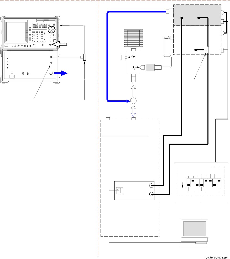
Figure 3 -28 A TP T est Setup – Adv antest R3267/3562
ti-cdma-06173.eps
TEST SETS OPTIMIZATION/ATP SET UP
INPUT 50 Ω
RF OUT
50 Ω
Advantest R3267 (Top) and R3562 (Bottom)
FREQ MONITOR
19.6608 MHZ CLOCK
REFERENCE FROM
SSI FREF OUT
SYNC MONITOR
EVEN SEC TICK
PULSE REFERENCE
FROM SSI TREF OUT
BNC
“T”
NOTE:
SYNTHE REF IN ON REAR OF SIGNAL GENERATOR IS
CONNECTED TO 10 MHZ REF OUT ON REAR OF
SPECTRUM ANALYZER
TOEXT TRIG
ON REAR OF
SPECTRUM
ANALYZER
RS232-GPIB
INTERFACE BOX
GPIB
CABLE
RS232 NULL
MODEM
CABLE
S MODE
DATA FORMAT
BAUD RATE
GPIB ADRSG MODE
ON
CDMA
LMF
DIP SWITCH SETTINGS
INPUT
50 Ω
RF OUT
50 Ω
BNC
“T”
SPECTRUM
ANALYZER
GPIB
SIGNAL GENERATOR
GPIB
SYNTHE
REF
IN
10 MHZ
OUT
EXT
TRIG IN
MOD TIME
BASE IN
EXT TRIG
* BLACK RECTANGLES
REPRESENT THE RAISED
PART OF SWITCHES
UNSHIELDED TWISTED
PAIR (UTP) CABLE
(RJ45 CONNECTORS)INTERNAL PCMCIA ETHERNET
NETWORK INTERFACE CARD (NIC)
TX/RX
TEST
CABLE
50 Ω
TERM.
DIRECTIONAL
COUPLER
(30 DB)
100-W ATT (MIN.)
NON-RADIATING
RF LOAD
TX TEST: 1O DB MINIMUM
IN-LINE ATTENUATOR
OR
TX/RX TEST
CABLE
UBS
CRMS/LMT
CUSTOMER
ENET
FREF
OUT
TREF
OUT
SSI
RX DIVTX/RX M
(DUPLEXED TX
AND RX)
IDRF
3 -42 68P09283A63 -5
FOA A UG 2007
1X UBS Macro B T S Optimization/A TP T est Equipment Set Up
Figure 3 -29 A TP T est Setup – Agilent E7495A or E7495B
ti-cdma-06175.eps
TEST SET ATP TEST SET UP
UNSHIELDED TWISTED PAIR (UTP)
CABLE (RJ45 CONNECTORS)
CDMA
LMF
INTERNAL
ETHERNET
CARD
RF INPUT 50 Ω
OR INPUT 50 Ω
COMMUNICATIONS
SYSTEM ANALYZER
50 Ω
TERM.
TX/RX
TEST
30 DB
DIRECTIONAL
COUPLER
100-W ATT (MIN.)
NON-RADIA TING
RF LOAD TX TEST
TX TEST: 1O DB MINIMUM
IN-LINE ATTENUATOR
ETHERNET HUB
RX TEST
TEST
CABLES
NOTE: USE THE SAME
CABLE SET FOR TX AND RX
ATP. SWITCH THE CABLES
DURING ALL ATP TESTS AS
SHOWN.
PORT 2
RF IN
PORT 1
RF OUT
AGILENT E7495A or E7495B
PORT 1
RF OUT
PORT 2
RF IN
SYNC MONITOR
EVEN SEC TICK
PULSE REFERENCE
FROM SSI TREF OUT
Use only
Agilent supplied
power adapter
GPS
GPIO
Serial 1
Serial 2
Power REF
50 MHz
Sensor
Ext Ref
In
Even Second
Sync In
Antenna
Port 1
RF Out / SWR
Port 2
RF In
INTERNAL PCMCIA ETHERNET
NETWORK INTERFACE CARD (NIC)
POWER METER
(SEE NOTE FOR RX TEST
ATTENUATION SELECTION)
NOTE: FOR RX TESTING, TOTAL RF PATH
ATTENUATION (CABLES+COUPLERS+ATTENUATORS)
MUST BE WITHIN THE FOLLOWING VALUES
SPECIFIED FOR EACH TYPE OF TEST SET:
E7495A: 25 TO 32 dB
E7495B: 10 TO 100 dB
2. WHEN USING THE E7495A, TX TESTS REQUIRE A
MINIMUM OF 30 DB ATTENUATION PLUS THE CABLE
LOSSES.
3. USE THE SAME CABLE SET FOR TX AND RX ATP.
SWITCH THE CABLES DURING ALL ATP TESTS AS
SHOWN.
4. IF BTS IS EQUIPPED WITH DUPLEXED RX/TX
SIGNALS, CONNECT THE TX TEST CABLE TO THE
DUPLEXED ANTENNA CONNECTOR.
EVEN SECOND
SYNC IN
UBS
RX DIV TX/RX M
(DUPLEXED TX
AND RX)
IDRF
CRMS/LMT
CUSTOMER
ENET
FREF
OUT
TREF
OUT
SSI
68P09283A63 -5 3 -43
FOA A UG 2007
T est Equipment Set Up Chapter 3: LMF Oper ation
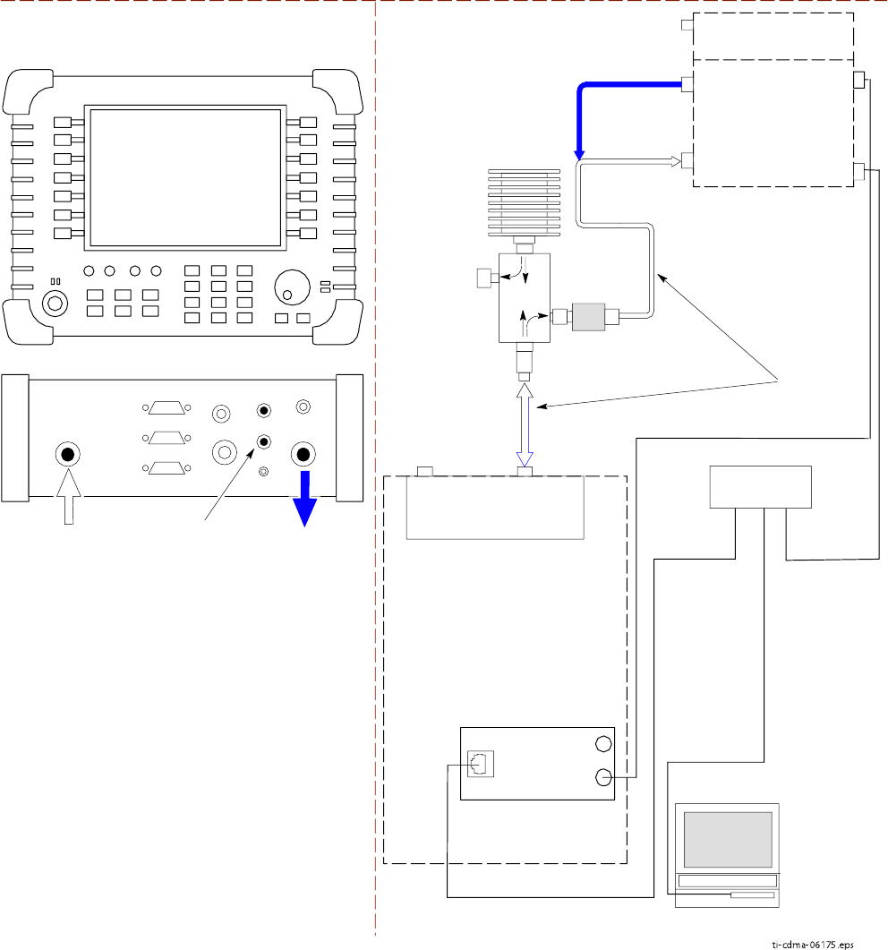
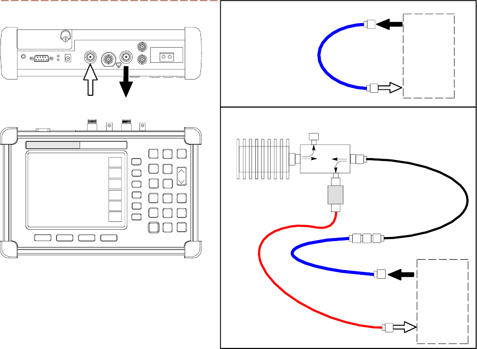
Figure 3 -30 A TP T est Setup – Anritsu MT8212B
TEST SET OPTIMIZATION/ATP SET UP
CDMA
LMF
INTERNAL OR PCMCIA ETHERNET
NETWORK INTERFACE CARD (NIC)
UNSHIELDED TWISTED PAIR (UTP)
CABLE (RJ45 CONNECTORS)
SERIAL
INTERFACE
COMMUNICATIONS
SYSTEM ANALYZER
RF IN
50 Ω
RF OUT
50 Ω
SYNC MONITOR
EVEN SEC TICK
PULSE REFERENCE
FROM SSI TREF OUT
RF IN
50 Ω
FREQ MONITOR
19.6608 MHZ CLOCK
REFERENCE FROM
SSI FREF OUT
ANRITSU MT8212B
RF OUT
50 Ω
TX TEST
RX TEST
RS232 SERIAL
INTERFACE CABLE
NOTES:
1. USE THE SAME CABLE SET FOR TX
AND RX ATP. SWITCH THE CABLES
DURING ATP TESTS AS SHOWN.
2. FOR RX TESTING (RSSI), TOTAL RF
PATH ATTENUATION
(CABLES+COUPLERS+ATTENUATORS)
MUST BE 65 dB OR GREATER.
SERIAL
INTERFACE
CONNECTOR
100-W ATT (MIN.)
NON-RADIA TING
RF LOAD
UBS
RX DIVTX/RX M
(DUPLEXED TX
AND RX)
IDRF
CRMS/LMT
CUSTOMER
ENET
FREF
OUT
TREF
OUT
SSI
ti-cdma-06207.eps
3 -44 68P09283A63 -5
FOA A UG 2007

1X UBS Macro B T S Optimization/A TP T est Equipment Connection to the LMF
Test Equipment Connection to the LMF■■■■■■■■■■■■■■■■■■■■■■■■■■■■■■■■■■■■■■■■■■■■■■■■■■■■■■■■■■■■■■
■
■
Test Equipment Connection
The LMF computer platform provides two types of hardware interfaces which support three
different test equipment communication methods.
•The COM hardware interface (RS -232) supports connection with both of the following
communication methods:
General Purpose Interface Bus (GPIB)
Direct serial connection
•The Ethernet interface supports the network test equipment communication method.
Additional information on each interface type is provided in the following subsections.
COM Port Interface
The LMF computer RS -232 serial bus interfaces are designated as COM connections or ports in
software. These interfaces support communication with test equipment connected to the LMF
computer either directly with a serial cable or through a GPIB interface device (GPIB box). The
LMF normally uses COM1 for the interface. COM2 is not used unless the LMF computer has
two RS -232 connectors. The COM port selected in the LMF can not be used for any other
purpose when the LMF is using it.
Selecting the COM port - P erform the following to select a COM port for use with test
equipment needing either a GPIB or a direct serial connection:
Procedure 3 -6 Selecting a COM P ort for GPIB or Serial T est Equipment Connection
1
From the LMF window menu bar select T ools >Options .
Result: The LMF Options window opens.
2
If the T est Equipment tab is not in the forefront, click the tab to bring it forward.
3
Click in the COM radio button in the GPIB/COM settings area.
Result: A black dot appears in the circle.
4
Select the COM port to use (normally COM1) from the dropdown in the P ort: box of
the GPIB/COM settings area.
5
Click the Save button to save the selection configuration for future LMF sessions.
6
Click the Close button to close the LMF Options window .
68P09283A63 -5 3 -45
FOA A UG 2007
T est Equipment Connection to the LMF Chapter 3: LMF Oper ation
Disconnecting and Reconnecting the LMF and the COM port - The LMF can be
disconnected from the active COM port by using the Disconnect P or t button in the GPIB/COM
settings area of the T est Equipment tab. Disconnecting the LMF may be needed, for example,
to use a HyperT erminal connection for a hardware Man Machine Interface (MMI) communication
session. P erform the following to disconnect or reconnect the LMF and the selected COM port.
Procedure 3 -7 Disconnect and R econnect the LMF and the Activ e COM P ort
1
From the LMF window menu bar select T ools >Options .
Result: The LMF Options window opens.
2
If the T est Equipment tab is not in the forefront, click the tab to bring it forward.
3
Disconnect
the LMF from the active COM port: click the Disconnect Port button in
the GPIB/COM settings area.
4
Reconnect
the LMF to the active COM port: click the Detect button in the GPIB T est
equipment or Serial T est Equipment area.
5
If no other operations are required in the LMF Options window click Close to close
the window .
Ethernet Interface
The LMF computer Ethernet interface supports communication with test equipment which
uses the network connection method. This interface uses Internet Protocol (IP) addressing to
differentiate each node on the network. Motorola recommends that the Ethernet connection be
done through an Ethernet hub. The hub connects to the LMF computer , the test equipment, and
the base station Local Area Network (LAN). Connection details are as follows:
T est equipment to hub – This is an Unshielded T wisted P air (UTP) Ethernet cable with two
10/100Base–TX 8 -contact modular connectors.
LMF to hub – Use one of the following cable types to connect the LMF to the Hub:
•Ethernet cable. Be sure the computer Network Interface Card (NIC) is set for either AUTO
or to use the 8–contact modular connector only .
•Coaxial cable between NIC and Hub. F or a computer NIC equipped with a 10Base–2 (BNC)
connector , use a BNC tee connector on the hub. If the hub does not have BNC connectors,
use a BNC–to–UTP adapter with the tee connector . Connect a coaxial cable between the
NIC and one end of the BNC tee crossbar .
Hub to base station– Use one of the following, depending on the type of base station to be
calibrated or tested:
•F or UBS with 10/100Base–T LAN : Connect an Ethernet cable between the hub and the S SI
CRMS/LMT CUSTOMER ENET connector .
3 -46 68P09283A63 -5
FOA A UG 2007
1X UBS Macro B T S Optimization/A TP T est Equipment Connection to the LMF
Addressing Methods
Different addressing methods are used for test equipment depending on the type of interface
connection it has. The different addressing methods are described in the following subsections.
GPIB Addresses
GPIB addresses can range from 1 through 30. The LMF will accept any address in that
range, but the numbers entered in the LMF Options window GPIB address box must match
the addresses set in the test equipment. Motorola recommends using 1for a CDMA signal
generator , 13 for a power meter , and 18 for a communications system analyzer . T o verify
and, if necessary , change the GPIB addresses of the test equipment, refer to the
Setting GPIB
Addresses
sections of Appendix D T est Equipment Preparation .
Serial Connection
This connection type uses a direct serial connection between the test equipment and the
LMF computer platform. The
Anritsu
MT8212B communications test set is an example of
test equipment using this type of connection. There are no specific addressing requirements
for this type of interface.
IP Addresses
T est equipment using the Network connection type use IP addresses to identify them on the
Ethernet LAN . The E7495A and E7495B communications test sets are examples of Network
connection test equipment. Setting the IP address in the test equipment is covered in the
specific test equipment (for example, Agilent E7495) set -up section of Appendix D T est
Equipment Preparation .
68P09283A63 -5 3 -47
FOA A UG 2007
T est Equipment Selection Chapter 3: LMF Oper ation
Test Equipment Selection■■■■■■■■■■■■■■■■■■■■■■■■■■■■■■■■■■■■■■■■■■■■■■■■■■■■■■■■■■■■■■
■
■
Test Equipment Selection
T est equipment selection is performed in the LMF Options window , accessed through T ools
>Options in the LMF window menu bar . The window has four tabs covering different
categories of options. T est equipment operations, including selection, are performed on the
T est Equipment tab. F or software release 2.20.0.x (R20), the test equipment list displayed on
this tab is context sensitive based on the Connection type selected.
•When GPIB is selected, only test equipment with a GPIB interface is displayed.
•When Serial is selected, only test equipment needing a direct serial connection is
displayed.
•When Network is selected, only test equipment needing an Ethernet connection is
displayed.
Manual and Autodetect Selection
T est equipment can be manually specified before or after the test equipment is connected. The
LMF does not try to determine if the test equipment is actually connected for manual selection.
The LMF can be commanded to automatically detect test equipment connected to it. This
autodetection feature is operated by a Detect button located in the test equipment list area for
each connection type (GPIB, Serial, or Network).
Selecting Test Equipment
There is a different set of test equipment selection procedures for each test equipment
connection type. These are:
•GPIB connection
•Serial connection
•Network (Ethernet) connection
Selection Procedures
T est equipment selection procedures are contained in the following subsections. Each
subsection is for a different connection type. Each subsection includes a procedure for manually
specifying test equipment items and a procedure to have the LMF automatically detect the
connected test equipment.
3 -48 68P09283A63 -5
FOA A UG 2007
1X UBS Macro B T S Optimization/A TP T est Equipment Selection
GPIB Interface Test Equipment Manual Selection and Autodetection
Prerequisites - The following must be done before performing these procedures:
•LMF computer and test equipment are both correctly connected to the GPIB box
•T est equipment is turned on
•GPIB addresses set in the test equipment have been verified as correct using the applicable
procedures in Appendix D T est Equipment Preparation .
Manual selection – T est equipment may be selected manually even if it is not connected to
the LMF .
Procedure 3 -8 Manually Selecting T est Equipment - GPIB Interface
1
In the LMF menu bar , select T ools >Options .
Result: The LMF Options window appears.
2
Click on the T est Equipment tab (if not in the forefront).
3
Click the GPIB radio button in the Connection T ype area.
Result: A black dot appears in the circle.
4
Click the COM radio button in the GPIB/COM settings area.
Result: A black dot appears in the circle.
5
Select the correct LMF computer serial port from the P ort: pick list (normally COM1 )
(Refer to the T est Equipment Connection to the LMF on page 3- 45 section of this chapter).
6
In the GPIB T est equipment area click the checkbox(es) of the test equipment being
used.
Result: Checkmarks appear in the boxes clicked on.
7
If one is not already displayed, type the GPIB address for each checked
piece of test equipment in the corresponding box labeled GPIB .
Recommended Addresses
1= CDMA Signal generator
13 = P ower Meter
18 = CDMA Analyzer
When the test equipment items are manually selected, the CDMA analyzer is
used only if a power meter is not selected.
Continued
68P09283A63 -5 3 -49
FOA A UG 2007
T est Equipment Selection Chapter 3: LMF Oper ation
Procedure 3 -8 Manually Selecting T est Equipment - GPIB Interface (Continued)
8
Click the Apply button. The button will darken until the selection is committed.
9
Click the Detect on startup checkbox in the Autodetection settings area to allow the
LMF to detect the test equipment automatically on application startup.A checkmark
appears in the box.
10
Click the Save button to save the selection configuration for future LMF sessions.
11
Click the Close button to close the LMF Options window .
When two devices of the same type have been selected, a window will appear
warning that more than one signal generator/power meter/ analyzer has been
chosen. Click the Continue button to close this window . The checkbox can be
clicked to prevent the window from being displayed again, if desired.
Automatically Selecting T est Equipment (Autodetection) – When using the
autodetection feature to select test equipment, the LMF determines which test equipment items
are actually communicating with the LMF .
Procedure 3 -9 A utodetecting T est Equipment - GPIB Interface
1
In the LMF menu bar , select T ools >Options .
Result: The LMF Options window appears.
2
Click on the T est Equipment tab (if not in the forefront).
3
Click the GPIB radio button in the Connection T ype area.
Result: A black dot appears in the circle.
4
Click the COM radio button in the GPIB/COM settings area.
Result: A black dot appears in the circle.
5
Select the correct LMF computer serial port from the P ort: pick list (normally COM1 )
(Refer to the T est Equipment Connection to the LMF on page 3- 45 section of this chapter).
Continued
3 -50 68P09283A63 -5
FOA A UG 2007
1X UBS Macro B T S Optimization/A TP T est Equipment Selection
Procedure 3 -9 A utodetecting T est Equipment - GPIB Interface (Continued)
6
If they are not already displayed, enter the GPIB address for each
piece of required test equipment, separated by commas, in the
GPIB Addresses: box in the GPIB T est equipment area.
Recommended Addresses
1= CDMA Signal generator
13 = P ower Meter
18 = CDMA Analyzer
In autodetection when both a power meter and a CDMA analyzer are
selected, the LMF uses the first item that is capable of performing RF power
measurement listed in the GPIB Addresses: box. The address for a CDMA
signal generator is normally 1, the address for a power meter is normally 13,
and the address for a CDMA analyzer is normally 18 . If 1,13,18 is listed
in the GPIB Addresses: box, the power meter ( 13 ) is used for RF power
measurements. When the test equipment items are manually selected, the
CDMA analyzer is used only if a power meter is not selected.
7
Click the Detect button. The button will darken until the selection is committed.
Result: F or each detected equipment item, a check will appear in its checkbox and its
GPIB address will appear in its GPIB box.
8
Click the Detect on startup checkbox in the Autodetection settings area to allow the
LMF to detect the test equipment automatically on application startup.
Result: A checkmark appears in the box.
9
Click the Save button to save the selection configuration for future LMF sessions.
10
Click the Close button to close the LMF Options window .
When two devices of the same type have been selected, a window will appear
warning that more than one signal generator/power meter/ analyzer has been
chosen. Click the Continue button to close this window . The checkbox can be
clicked to prevent the window from being displayed again, if desired.
Serial Interface Test Equipment Manual Selection and Autodetection
Prerequisites – The following must be done before performing these procedures:
•T est equipment is correctly connected to the LMF computer RS -232 connector with
a serial cable
•T est equipment is turned on
68P09283A63 -5 3 -51
FOA A UG 2007

T est Equipment Selection Chapter 3: LMF Oper ation
Manual selection – T est equipment may be selected manually even if it is not connected to
the LMF .
Procedure 3 -10 Manually Selecting T est Equipment - Serial Interface
1
In the LMF menu bar , select T ools >Options .
Result: The LMF Options window appears.
2
Click on the T est Equipment tab (if not in the forefront).
3
Click the Serial radio button in the Connection T ype area.
Result: A black dot appears in the circle.
4
Click the COM radio button in the GPIB/COM settings area.
Result: A black dot appears in the circle.
5
Select the correct LMF computer serial port from the P ort: pick list (normally COM1 )
(Refer to the T est Equipment Connection to the LMF on page 3- 45 section of this chapter).
6
In the Serial T est equipment , area click the checkbox(es) of the test equipment being
used.
Result: Checkmarks appear in the box(es) clicked on.
7
Click the Apply button. The button will darken until the selection is committed.
8
Click the Detect on startup checkbox in the Autodetection settings area to allow the
LMF to detect the test equipment automatically on application startup.
Result: A checkmark appears in the box.
9
Click the Save button to save the selection configuration for future LMF sessions.
10
Click the Close button to close the LMF Options window .
Automatically Selecting T est Equipment (Autodetection) – When using the
autodetection feature to select test equipment, the LMF determines which test equipment items
are actually communicating with the LMF .
Procedure 3 -11 A utodetecting T est Equipment - Serial Interface
1
In the LMF menu bar , select T ools >Options .
Result: The LMF Options window appears.
2
Click on the T est Equipment tab (if not in the forefront).
3
Click the Serial radio button in the Connection T ype area.
Result: A black dot appears in the circle.
Continued
3 -52 68P09283A63 -5
FOA A UG 2007

1X UBS Macro B T S Optimization/A TP T est Equipment Selection
Procedure 3 -11 A utodetecting T est Equipment - Serial Interface (Continued)
4
Click the COM radio button in the GPIB/COM settings area.
Result: A black dot appears in the circle.
5
Select the correct LMF computer serial port from the P ort: pick list (normally COM1 )
(Refer to the T est Equipment Connection to the LMF on page 3- 45 section of this chapter).
6
Choose the test equipment on the Serial T est Equipment list by clicking the
corresponding checkbox.
Result: A checkmark appears in the box.
7
Click the Detect button. The button will darken until the selection is committed.
Result: F or each detected equipment item, a check will appear in its checkbox.
8
Click the Detect on startup checkbox in the Autodetection settings area to allow the
LMF to detect the test equipment automatically on application startup.
Result: A checkmark appears in the box.
9
Click the Save button to save the selection configuration for future LMF sessions.
10
Click the Close button to close the LMF Options window .
Network Interface Test Equipment Manual Selection and Autodetection
Prerequisites– The following must be done before performing these procedures:
•Be sure that no other equipment is connected to the LMF .
•T est equipment is correctly connected to the LMF computer through the Ethernet LAN
•The IP address is set in the test equipment as specified in the test equipment model (for
example, Agilent E7495) set -up section of Appendix D T est Equipment Preparation .
•T est equipment is turned on
Manual selection – T est equipment may be selected manually even if it is not connected to
the LMF .
Procedure 3 -12 Manually Selecting T est Equipment - Network Interface
1
In the LMF menu bar , select T ools >Options .
Result: The LMF Options window appears.
2
Click on the T est Equipment tab (if not in the forefront).
3
Click the Network radio button in the Connection T ype area.
Result: A black dot appears in the circle.
Continued
68P09283A63 -5 3 -53
FOA A UG 2007

T est Equipment Selection Chapter 3: LMF Oper ation
Procedure 3 -12 Manually Selecting T est Equipment - Network Interface (Continued)
4
In the Ethernet T est equipment area click the checkbox(es) of the test equipment
being used.
Result: Checkmarks appear in the box(es) clicked on.
5
If it is not already displayed, enter the IP address for the required piece test equipment in
the IP box in the Ethernet T est equipment area.
6
Click the Apply button. The button will darken until the selection is committed.
7
Click the Detect on startup checkbox in the Autodetection settings area to allow the
LMF to detect the test equipment automatically on application startup.
Result: A checkmark appears in the box.
8
Click the Save button to save the selection configuration for future LMF sessions.
9
Click the Close button to close the LMF Options window .
Automatically Selecting T est Equipment (Autodetection) – When using the
autodetection feature to select test equipment, the LMF determines which test equipment items
are actually communicating with the LMF .
Procedure 3 -13 A utodetecting T est Equipment - Network Interface
1
In the LMF menu bar , select T ools >Options .
Result: The LMF Options window appears.
2
Click on the T est Equipment tab (if not in the forefront).
3
Click the Network radio button in the Connection T ype area.
Result: A black dot appears in the circle.
4
If it is not already displayed, enter the IP address for the required piece test equipment in
the IP box in the Ethernet T est equipment area.
5
Click the Detect button. The button will darken until the selection is committed.
Result: F or each detected equipment item, a check will appear in its checkbox.
6
Click the Detect on startup checkbox in the Autodetection settings area to allow the
LMF to detect the test equipment automatically on application startup.
Result: A checkmark appears in the box.
7
Click the Save button to save the selection configuration for future LMF sessions.
8
Click the Close button to close the LMF Options window .
3 -54 68P09283A63 -5
FOA A UG 2007

1X UBS Macro B T S Optimization/A TP T est Set Calibr ation
Test Set Calibration
■■■■■■■■■■■■■■■■■■■■■■■■■■■■■■■■■■■■■■■■■■■■■■■■■■■■■■■■■■■■■■
■
■
Test Set Calibration Background
Proper test equipment calibration ensures that the test equipment and associated test cables do
not introduce measurement errors, and that measurements are correct.
If the test equipment set being used to interface with the base station has been
calibrated and maintained as a set, this procedure does not need to be performed.
(T est equipment set includes LMF computer , communications test set, additional test
equipment, associated test cables, and adapters.)
This procedure must be performed
before
beginning the optimization. V erify all test equipment
(including all associated test cables and adapters actually used to interface all test equipment
and the base station) has been calibrated and maintained as a set.
If an y piece of test equipment, test cable, or RF adapter , that mak es up the calibr ated
test equipment set, has been replaced, re -calibr ation must be performed. F ailure to
do so can introduce measurement errors, resulting in incorrect measurements and
degr adation to system performance.
Calibration of the communications test set (or equivalent test equipment) must
be performed at the site before calibrating the overall test set. Calibrate the test
equipment
after
it has been allowed to warm -up and stabilize for a
minimum of 60
minutes
.
68P09283A63 -5 3 -55
FOA A UG 2007
T est Set Calibr ation Chapter 3: LMF Oper ation
Calibration Procedures Included
Automatic
Procedures included in this section use the LMF automated calibration routines to determine
path losses of the supported communications analyzer , power meter , associated test cables,
adapters, and (if used) antenna switch that make up the overall calibrated
test equipment set
.
A fter calibration, the gain/loss offset values are stored in a test measurement offset file on
the LMF computer .
Manual
Agilent E4406A T ransmitter T ester - The E4406A does not support the power level
zeroing calibration performed by the LMF . If this instrument is to be used for Bay Level Offset
calibration and calibration is attempted with the LMF Calibrate T est Equipment function, the
LMF will return a status window failure message stating that zeroing power is not supported
by the E4406A. Refer to Appendix D T est Equipment Preparation for instructions on using
the instrument’s self -alignment (calibration) function prior to performing Bay Level Offset
calibration.
P ower Meters - Manual power meter calibration procedures to be performed prior to
automated calibration are included in Appendix D T est Equipment Preparation .
Cable Calibration - Manual cable calibration procedures using the Advantest R3465
communications system analyzer are provided in Appendix D T est Equipment Preparation ,
if needed.
Prerequisites
Ensure the following prerequisites have been met before proceeding:
•T est equipment is correctly connected and turned on.
•T est equipment addressing is set as required for the connection type being used (GPIB,
Serial, Network)
Calibrate Test Equipment Function (Except Agilent E4406A and
Anritsu MT8212B)
The Calibrate T est Equipment function zeros the power measurement level of the test
equipment item to be used for TX calibration and audit. If both a power meter and an analyzer
are connected, only the power meter is zeroed.
3 -56 68P09283A63 -5
FOA A UG 2007

1X UBS Macro B T S Optimization/A TP T est Set Calibr ation
1. The Agilent E4406A transmitter tester does not support power measurement
level zeroing. Refer to the T est Equipment Calibration section of Appendix F
for E4406A calibration.
2. P ower measurement zeroing and other required calibration procedures for the
Anritsu
MT8212B are included in the Calibrating the
Anritsu
MT8212B on page
3 - 57 subsection below .
Prerequisites
•T est equipment to be zeroed has been connected correctly for tests to be run.
•T est equipment has been selected in the LMF ( T est Equipment Selection on page 3 - 48 )
and detected.
Procedure
P erform the following to calibrate the test equipment.
Procedure 3 -14 Calibr ate T est Equipment - P ower Measurement Z eroing
1
From the Util menu, select Calibrate T est Equipment from the pull-down menu. A
Directions window is displayed.
2
F ollow the directions provided.
3
Click on Continue to close the Directions window and start the calibration process. A
status report window is displayed.
4
Click on OK to close the status report window .
Calibrating the Anritsu MT8212B
Three types of calibration are required for the MT812B. These are:
•Zero out power meter
•Calibrate TX Analyzer
•Calibrate CW Generator
Procedures for each type of calibration is covered in the following subsections.
68P09283A63 -5 3 -57
FOA A UG 2007
T est Set Calibr ation Chapter 3: LMF Oper ation
Zero Out Power Meter
Before using the MT8212B test set to perform RF power measurement, the test set internal
power meter function must be zeroed.
Prerequisites – The following must be done before the zeroing out the power meter:
•The test set is connected to the LMF computer serial port with the
Anritsu
800 -441 RS -232
serial interface cable
•T est equipment is turned on and has warmed up for at least 60 minutes.
•T est equipment has been selected/detected in the LMF ( T est Equipment Selection on
page 3 - 48 )
Zero out power meter – P erform the following to zero out the power meter function before
performing RF power measurements.
Procedure 3 -15 Anritsu MT8212B Multi -function T est Set Z ero Out P ower Meter
1
In the LMF menu bar select Util >Calibrate T est Equipment .
Result: ACalibrate
Anritsu
MT8212B window appears.
2
Click in the Option for zero out power meter on
Anritsu
MT8212B radio button in
the Zero Out P ower Meter area.
Result: A black dot appears in the circle.
3
Click on OK .
Result: ADirections window is displayed.
4
F ollow the directions provided.
Result: A status report window will open.
5
Click on OK to close the status report window .
Calibrate TX Analyzer
TX Analyzer calibration should be accomplished before performing any A TP operations with
the MT8212B.
Prerequisites – The following must be done before the CW generator calibration:
•The test set is connected to the LMF computer serial port with the
Anritsu
800 -441 RS -232
serial interface cable
•T est equipment has been selected/detected in the LMF ( T est Equipment Selection on
page 3 - 48 )
•Additional items must be available for the TX Analyzer calibration method chosen as
indicated in the following:
3 -58 68P09283A63 -5
FOA A UG 2007
1X UBS Macro B T S Optimization/A TP T est Set Calibr ation
•Standard Open -Short -Load Components calibration:
Anritsu
22N50 Open/Short, DC to 18 GHz, N(m) connector , 50 ohm
Anritsu
SM/PL precision load, DC -to -4 GHz, 42 dB, N(m) connector , 50 ohm
•Standard InstaCal™ calibration:
Anritsu
ICN50
InstaCal
calibration module, 2 MHz to 4 GHz, N(m) connector , 50 ohm
TX analyzer calibration – P erform the following to calibrate the MT8212B TX analyzer
function..
Procedure 3 -16 Anritsu MT8212B Multi -function T est Set TX Analyz er Calibr ation
1
In the LMF menu bar select Util >Calibrate T est Equipment .Calibrate
Anritsu
MT8212B window appears
2
Click in the radio button in the Calibrate TX Analyzer area.
Result: A black dot appears in the circle.
3
Select the required frequency band from the dropdown list in the F requency Band: box.
The dropdown list in the F requency Band: box is automatically populated
with selections for the base station the LMF is logged into .
4
Enter the channel number to be calibrated in the Channel box.
5
Select the desired calibration method from the dropdown list in the Calibration Method
box.
6
Click OK .
Result: ADirections window is displayed.
7
F ollow the directions provided.
8
When actions required by directions have been completed, click on Continue to close the
Directions window and start the generator calibration process.
Result: A status report window is displayed.
9
Click on OK to close the status report window .
Calibrate CW Generator
Before using the MT8212B test set to perform base station RS SI testing, the test set internal
Continuous W ave (CW) generator must be calibrated.
68P09283A63 -5 3 -59
FOA A UG 2007
T est Set Calibr ation Chapter 3: LMF Oper ation
Prerequisites - The following must be done before the CW generator calibration:
•The test set is connected to the LMF computer serial port with the
Anritsu
800 -441 RS -232
serial interface cable
•T est equipment is turned on and has warmed up for
at least 60 minutes
.
•T est equipment has been selected/detected in the LMF ( T est Equipment Selection on
page 3 - 48 )
•RX cable(s) used in the calibration process must be calibrated for the channel for which the
CW generator is to be calibrated (refer to Figure 3 -34 and Calibrating cables on page 3 - 65 )
CW generator calibration - P erform the following to calibrate the MT8212B internal CW
generator before performing RS SI testing with this test set.
Procedure 3 -17 Anritsu MT8212B Multi -function T est Set CW Gener ator Calibr ation
1
In the LMF menu bar select Util >Calibrate T est Equipment .
Result: Calibrate
Anritsu
MT8212B window appears
2
Click in the radio button in the Calibrate CW Generator area.
Result: A black dot appears in the circle.
3
Select the required frequency band from the dropdown list in the F requency Band: box.
The dropdown list in the F requency Band: box is automatically populated
with selections for the base station the LMF is logged into .
4
Enter the channel or channels to be calibrated in the Channel(s) box (separate multiple
channels with a comma and no space).
When two or more channels numbers are entered, the generator will be
calibrated for each channel. Interpolation will be accomplished for other
channels as required for TX calibration. Channels must be within the range of
the selected frequency band.
5
Click OK .
Result: ADirections window is displayed.
6
F ollow the directions provided.
7
When actions required by directions have been completed, click on Continue to close the
Directions window and start the generator calibration process.
Result: A status report window is displayed.
3 -60 68P09283A63 -5
FOA A UG 2007

1X UBS Macro B T S Optimization/A TP T est Set Calibr ation
Procedure 3 -17 Anritsu MT8212B Multi -function T est Set CW Gener ator Calibr ation
(Continued)
8
Click on OK to close the status report window .
68P09283A63 -5 3 -61
FOA A UG 2007
Setting and Editing Gener ator Calibr ation Data Chapter 3: LMF Oper ation
Setting and Editing Generator Calibration Data■■■■■■■■■■■■■■■■■■■■■■■■■■■■■■■■■■■■■■■■■■■■■■■■■■■■■■■■■■■■■■
■
■
Generator Calibration Data
Generator calibration data is automatically stored in a generator calibration data file by the
LMF when the generator function of a test equipment item is calibrated using the LMF Util >
Calibrate T est Equipment functions. Stored data values can be edited with this procedure,
or new data can be entered manually for a test equipment item generator function which was
calibrated without using the LMF .
This procedure MUST be used to enter calibr ation data v alues for an y MT8212B which
w as calibrated without using the LMF . F ailure to do this will gener ate incorrect results
for an y RS SI testing performed.
Prerequisites
The LMF is logged into a BTS .
Set or Edit Generator Calibration Data
P erform the following to enter new calibration data or edit existing data.
Procedure 3 -18 Set or Edit Gener ator Calibr ation Data
1
In the LMF menu bar select Util >Edit >Generator Calibration Data .
Result: Generator Calibration Data window appears with tabs for each type of
generator test equipment calibrated using the LMF (for example, the
Anritsu
MT8212B).
2
Click on the tab for the generator with data to be edited or entered.
Result: The tab moves to the forefront.
3
T o edit existing values, click in the data field to be edited and make required changes.
4
T o add a new channel and its data:
1. Click the Add Row button.
2. Click in the field where data is to be entered; for example, F requency Band ,
Channel # , or P ower (dB) .
3. Enter the desired value.
Continued
3 -62 68P09283A63 -5
FOA A UG 2007

1X UBS Macro B T S Optimization/A TP Setting and Editing Gener ator Calibr ation Data
Procedure 3 -18 Set or Edit Gener ator Calibr ation Data (Continued)
F or F requency Band fields, select the required frequency band from the
dropdown provided. Selections are made available for the BTS which the LMF
is logged into .
5
T o delete a row , click in the row , and then click the Delete Row button.
6
F or each tab with changes, click the Save button to save the displayed values.
•V alues entered after the Save button was used will not be saved.
•If generator calibration values exist for two different channels assigned to
one frequency band, the LMF will interpolate for all other channels on
this frequency band.
•Entered values will be used by the LMF as soon as they are saved. It is not
necessary to log out and log back into the LMF for changes to take effect.
68P09283A63 -5 3 -63
FOA A UG 2007
Cable Calibr ation Chapter 3: LMF Oper ation
Cable Calibration
■■■■■■■■■■■■■■■■■■■■■■■■■■■■■■■■■■■■■■■■■■■■■■■■■■■■■■■■■■■■■■
■
■
Calibrating Cables Overview
The cable calibration function measures the loss (in dB) for the TX and RX cables that are to be
used for testing. A CDMA analyzer is used to measure the loss of each cable configuration (TX
cable configuration and RX cable configuration). The cable calibration consists of the following:
•Measuring the loss of a short cable – This is required to compensate for any
measurement error of the analyzer . The short cable (used only for the calibration process)
is used in series with both the TX and RX cable configuration when measuring. The
measured loss of the short cable is deducted from the measured loss of the TX and RX
cable configuration to determine the actual loss of the TX and RX cable configurations.
The result is then adjusted out of both the TX and RX measurements to compensate for
the measured loss.
•Measuring the short cable plus the RX cable configuration loss – The RX cable
configuration normally consists only of a coax cable with type -N connectors that is long
enough to reach from the BTS RX port of the test equipment. Refer to Figure 3 -31 ,
Figure 3 -32 ,Figure 3 -33 , or Figure 3 -34 for specific cable and connection requirements for
each type of communications system analyzer .
•Measuring the short cable plus the TX cable configuration loss – The TX cable
configuration normally consists of two coax cables with type N connectors and a directional
coupler , a load, and an additional attenuator (if required by the specified BTS). The total
loss of the path loss of the TX cable configuration must be as required for the BTS (normally
30 or 50 dB). Refer to Figure 3 -31 ,Figure 3 -32 ,Figure 3 -33 , or Figure 3 -34 for specific
cable and connection requirements for each type of communications system analyzer .
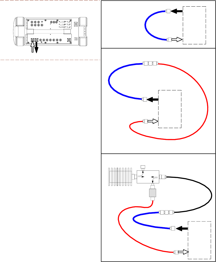
Cable Calibration Set–up Diagrams
Figure 3 -31 and Figure 3 -32 show the cable calibration set–up for various supported test sets.
The left side of the diagram depicts the location of the input and output connectors of each test
equipment item, and the right side details the set up for each test.
Calibrate Test Cabling using Communications System Analyzer
Cable Calibration is used to calibrate both TX and RX test cables.
3 -64 68P09283A63 -5
FOA A UG 2007
1X UBS Macro B T S Optimization/A TP Cable Calibr ation
Prerequisites
Ensure the following prerequisites have been met before proceeding:
•One of the following:
LMF computer serial port and test equipment are connected to the GPIB box
F or MT8212B, the test equipment is connected to the LMF computer serial port
F or E7495A/B, the LMF computer NIC and the E7495 are connected to the Ethernet
hub (
T est Equipment Connection
section)
•T est equipment is turned on and has warmed up for at least 60 minutes.
•T est equipment has been selected/detected in the LMF (Refer to the
Selection Procedures
subsection of the
T est Equipment Selection
section)
Calibrating cables
Refer to Figure 3 -31 ,Figure 3 -32 ,Figure 3 -33 , or Figure 3 -34 and perform the following to
calibrate the test cable configurations.
Procedure 3 -19 A utomatic Cable Calibr ation
1
From the Util menu, select Cable Calibration .
Result: ACable Calibration window is displayed.
2
Enter the channel number(s) in the Channels box.
Multiple channel numbers must be separated with a comma and no space (for
example; 200,800). When two or more channel numbers are entered, the cables
are calibrated for each channel. Interpolation is accomplished for other channels
as required for TX calibration.
3
In the Cable Calibration pick list select one of the following:
•TX and RX Cable Cal
•TX Cable Cal
•RX Cable Cal
4
Click OK and follow the direction displayed for each step. A status report window displays
the results of the cable calibration.
68P09283A63 -5 3 -65
FOA A UG 2007
Cable Calibr ation Chapter 3: LMF Oper ation
Figure 3 -31 Cable Calibr ation T est Setup – Agilent 8935
ti-cdma-06176.eps
HEWLETT-P ACKARD MODEL HP 8935
DUPLEX
OUT
ANT
IN
SUPPORTED TEST SETS
100-W ATT (MIN)
NON-RADIA TING
RF LOAD
TEST
SET
A. SHORT CABLE CAL
SHORT
CABLE
B. RX TEST SETUP
TEST
SET
C. TX TEST SETUP
CALIBRATION SET UP
N-N FEMALE
ADAPTER
RX
CABLE
TX
CABLE
SHORT
CABLE
TEST
SET
RX
CABLE
SHORT
CABLE
N-N FEMALE
ADAPTER
DIRECTIONAL COUPLER
(30 DB)
50Ω TERM.
10 DB MINIMUM
IN-LINE ATTENUATOR
TX CABLE FOR
DRDC TX TEST
CABLE CALIBRATION
3 -66 68P09283A63 -5
FOA A UG 2007
1X UBS Macro B T S Optimization/A TP Cable Calibr ation
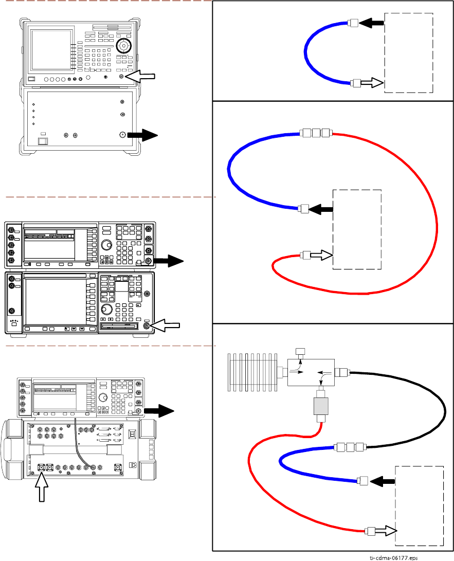
Figure 3 -32 Cable Calibr ation T est Setup – Adv antest R3267/R3562,E4406A/E4432B ,
and Agilent E4432/8935 Series E6380A
ti-cdma-06177.eps
SUPPORTED TEST SETS
100-W ATT (MIN)
NON-RADIA TING
RF LOAD
TEST
SET
A. SHORT CABLE CAL
SHORT
CABLE
B. RX TEST SETUP
TEST
SET
C. TX TEST SETUP
CALIBRATION SET UP
N-N FEMALE
ADAPTER
RX
CABLE
TX
CABLE
SHORT
CABLE
TEST
SET
RX
CABLE
SHORT
CABLE
N-N FEMALE
ADAPTER
RF IN
RF OUT
ADVANTEST R3267 (TOP) AND R3562 (BOTTOM)
EXT TRIG IN
MOD TIME BASE IN
(EXT REF IN)
RF
INPUT 50
OHM
RF
OUTPUT
50 OHM
AGILENT E4432B (TOP) AND E4406A (BOTTOM)
50 Ω TERM.
10 DB MINIMUM
IN-LINE ATTENUATOR
DIRECTIONAL COUPLER
(30 DB)
AGILENT E4432B (TOP) AND 8935 SERIES
E6380A (BOTTOM)
RF
OUTPUT
50 Ω
ANT
IN
NOTE:
10 MHZ IN on rear of signal generator is connected to
10 MHZ REF OUT on side of CDMA Base Station Test Set
TX CABLE FOR
DUPLEXED TX/RX
TEST CABLE
CALIBRATION
NOTE:
SYNTHE REF IN on rear signal generator is
connected to 10 MHZ OUT on rear of spectrum
analyzer
68P09283A63 -5 3 -67
FOA A UG 2007
Cable Calibr ation Chapter 3: LMF Oper ation
Figure 3 -33 Cable Calibr ation T est Setup – Agilent E7495A and E7495B
ti-cdma-06178.eps
TEST
SET
A. SHORT CABLE CAL
SHORT
CABLE
CALIBRATION SET UP
100-W ATT (MIN)
NON-RADIA TING
RF LOAD
B. RX and TX TEST SETUP
10 DB MIMIMUM
IN-LINE ATTENUATOR
N-N FEMALE
ADAPTER
TX
CABLE
DIRECTIONAL
COUPLER
(30 DB)
50 Ω
TERM.
10 DB PAD
10 DB PAD
SHORT
CABLE
10 DB PAD
10 DB PAD
TEST
SET
SUPPORTED TEST SETS
AGILENT E7495A OR E7495B
PORT 1
RF OUT
PORT 2
RF IN
Use only
Agilent supplied
power adapter
GPS
GPIO
Serial 1
Serial 2
Power REF
50 MHz
Sensor
Ext Ref
In
Even Second
Sync In
Antenna
Port 1
RF Out / SWR
Port 2
RF In
RX
CABLE
NOTES:
1. FOR RX TESTING, TOTAL RF PATH
ATTENUATION
(CABLES+COUPLERS+ATTENUATORS)
MUST BE WITHIN THE VALUES
SPECIFIED BELOW FOR EACH TYPE
OF TEST SET:
E7495A: 25 TO 32 dB
E7495B: 10 TO 100 dB
2. WHEN USING THE E7495A, TX
TESTS REQUIRE A MINIMUM OF 30 DB
ATTENUATION PLUS THE CABLE
LOSSES.
TX CABLE FOR
DUPLEXED TX/RX
TEST CABLE
CALIBRATION
3 -68 68P09283A63 -5
FOA A UG 2007
1X UBS Macro B T S Optimization/A TP Cable Calibr ation
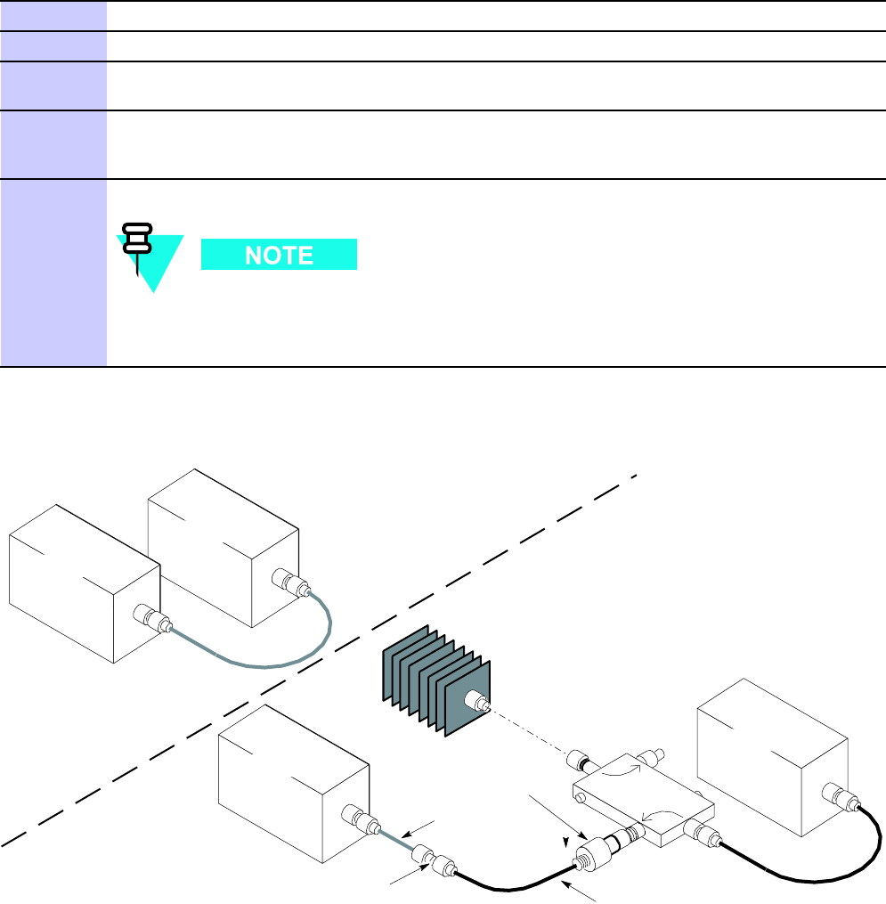
Figure 3 -34 Cable Calibr ation T est Setup – Anritsu MT8212B
SUPPORTED TEST SETS
100-W ATT (MIN.)
NON-RADIA TING
RF LOAD
TEST
SET
A. SHORT CABLE CAL
SHORT
CABLE
TEST
SET
C. RX and TX TEST SETUP
CALIBRATION SET UP
N-N FEMALE
ADAPTER
SHORT
CABLE
50Ω TERM.
TX TESTS: 10 DB MINIMUM
IN-LINE ATTENUATOR
RX TEST: 35 DB MINIMUM
IN-LINE ATTENUATOR
DIRECTIONAL COUPLER
(30 DB)
RF IN
50ΩRF OUT
50Ω
ANRITSU MT8212B
TX AND RX
CABLE
TX AND RX
CABLE
NOTE: FOR RX TESTING (RSSI), TOTAL
RF PATH ATTENUATION
(CABLES+COUPLERS+ATTENUATORS)
MUST BE 65 dB OR GREATER.
ti-cdma-06208.eps
Calibrate Test Cabling Using Signal Generator & Spectrum
Analyzer
Manual cable calibration can be performed by following Procedure 3 -20 to calibrate the
TX/
duplexed
RX cables using a signal generator and spectrum analyzer . Refer to Figure 3 -35 ,
if required. F ollow Procedure 3 -21 to calibrate the
non
–duplexed RX cables using the signal
generator and spectrum analyzer . Refer to Figure 3 -36 , if required.
68P09283A63 -5 3 -69
FOA A UG 2007
Cable Calibr ation Chapter 3: LMF Oper ation
TX and Duplexed RX Cable Calibration
Procedure 3 -20 Calibr ating TX and Duplex ed RX Cables Using Signal Gener ator and Spectrum
Analyz er
1
Connect a short test cable between the spectrum analyzer and the signal generator .
2
Set signal generator to 0 dBm at the customer frequency .
3
Use a spectrum analyzer to measure signal generator output (see Figure 3-35 A) and record
the value.
4
Connect the spectrum analyzer’s short cable to Figure 3-35 point B, (as shown in the lower
right portion of the diagram) to measure cable output at customer frequency . Record the
value at point B,
5
Calibration factor = A - B. Example: Cal = -1 dBm - (-53.5 dBm) = 52.5 dB
The short cable is used for calibration only . It is part of the final test setup. A fter
calibration is completed, rearrange any cables. Use the equipment setup, as is, to
ensure test procedures use the correct calibration factor .
Figure 3 -35 TX and Duplex ed RX Cable Calibr ation
50 OHM
TERMINATION
30 DB
DIRECTIONAL
COUPLER
SPECTRUM
ANALYZER
A
40W NON-RADIATING
RF LOAD
B
SHORT TEST CABLE
THIS WILL BE THE TX TEST CABLE CONNECTION TO THE
POWER SENSOR OR COMMUNICATIONS TEST SET INPUT
IPORT DURING TX CALIBRATION AND ATP TESTS.
SHORT
TEST
CABLE
CABLE FROM 10 DB MINIMUM @ 20W ATTENUATOR
TO THE POWER SENSOR OR COMMUNICATION
TEST SET.
10DB MINIMUM, 20 W
IN-LINE ATTENUATOR
SPECTRUM
ANALYZER
SIGNAL
GENERATOR
SIGNAL
GENERATOR
ti-cdma-00145.eps
3 -70 68P09283A63 -5
FOA A UG 2007
1X UBS Macro B T S Optimization/A TP Cable Calibr ation
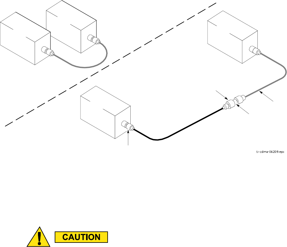
Non–duplexed RX Cable Calibration
Procedure 3 -21 Calibr ating RX Cables Using a Signal Gener ator and Spectrum
Analyz er
1
Connect a short test cable to the spectrum analyzer and connect the other end to the Signal
Generator .
2
Set signal generator to -10 dBm at the customer’s RX frequency .
3
Use spectrum analyzer to measure signal generator output (see Figure 3-36 ,A) and record
the value for A.
4
Connect the test setup, as shown in the lower portion of the diagram to measure the output at
the customer’s RX frequency . Record the value at Figure 3-36 , point B.
5
Calibration factor = A - B.
Example:
Cal = -12 dBm - (-14 dBm) = 2 dBm
6
The short cable is used for
calibration only
. It is
not
part of the final test setup.
A fter calibration is completed,
do not
rearrange any cables. Use the equipment
setup as is to ensure test procedures use the correct calibration factor .
68P09283A63 -5 3 -71
FOA A UG 2007
Cable Calibr ation Chapter 3: LMF Oper ation
Figure 3 -36 Non -Duplex RX Cable Calibr ation
ti-cdma-06209.eps
SPECTRUM
ANALYZER
SIGNAL
GENERATOR
A
B
SPECTRUM
ANALYZER
SHORT
TEST
CABLE
SHORT TEST
CABLE
CONNECTION TO THE COMMUNICATION
TEST SET OUTPUT PORT
DURING RX MEASUREMENTS.
SIGNAL
GENERATOR
BULLET
CONNECTOR
CONNECTION TO THE RX PORTS
DURING RX MEASUREMENTS.
LONG
CABLE 2
Setting Cable Loss Values
Cable loss values for the TX and RX test cable configurations are normally set by accomplishing
cable calibration using the applicable test equipment. The resulting values are stored in the
cable loss files. The cable loss values can also be set/changed manually .
If cable calibr ation w as performed without using the LMF , cable loss v alues must be
manually entered in the LMF database. F ailure to do this will result in inaccur ate UBS
calibr ation and reduced site performance.
Prerequisites
LMF is logged into the UBS
3 -72 68P09283A63 -5
FOA A UG 2007
1X UBS Macro B T S Optimization/A TP Cable Calibr ation
Procedure
P erform the following to set cable loss values.
Procedure 3 -22 Setting Cable Loss V alues
1
In the LMF menu bar , click on Util >Edit >Cable Loss
2
In the data entry pop–up window , select
one
of the following:
•TX Cable Loss
•RX Cable Loss
3
T o add a new channel number , click on Add Row , and click in Channel# and Loss (dBm)
columns and enter the desired values.
4
T o edit existing values, click in the data box to be changed and change the value.
5
T o delete a row , click on the row and then click on the Delete Row button.
6
T o save displayed values, click on the Save button.
7
T o exit the window , click on the Dismiss button.
V alues entered/changed after the Save button was used are not saved.
•If cable loss values exist for two different channels, the LMF will interpolate
for all other channels.
•Entered values are used by the LMF as soon as they are saved. Logging out
and logging in again is not necessary .
68P09283A63 -5 3 -73
A UG 2007 FOA
Cable Calibr ation Chapter 3: LMF Oper ation
3 -74 68P09283A63 -5
FOA A UG 2007

C h a p t e r
4
Acceptance Test Procedures■■■■■■■■■■■■■■■■■■■■■■■■■■■■■■■■■■■■■■■■■■■■■■■■■■■■■■■■■■■■■■
■
■
■
■
68P09283A63 -5 4 -1
A UG 2007 FOA

Introduction to A TP Chapter 4: Acceptance T est Procedures
Introduction to ATP■■■■■■■■■■■■■■■■■■■■■■■■■■■■■■■■■■■■■■■■■■■■■■■■■■■■■■■■■■■■■■
■
■
Introduction
General
The Acceptance T est Procedures (A TP) allow Cellular Field Engineers (CFEs) to run automated
acceptance tests on all UBS subsystem devices equipped in the NEC using the LMF and the
test equipment it supports.
LMF User Interface
This chapter provides procedures for performing acceptance testing from the LMF Graphical
User Interface (GUI) environment, the recommended method. The GUI provides the advantages
of simplifying the LMF user interface, reducing the potential for mis -keying commands and
associated parameters, and speeding up the execution of complex operations involving multiple
command strings. If it is believed the LMF command line interface (CLI) will provide additional
insight into A TP operation or unexpected test results, refer to LMF CLI Reference.
Test Reports
The CFE can choose to save the results of A TP tests to a report file from which A TP reports are
generated for later printing. See the Generating an A TP Report section in this chapter .
Test Equipment Selection
Because test equipment functions during acceptance testing are controlled by the LMF directly ,
only the test equipment models supported by the LMF can be used.
1. Before using the LMF , read the Dev eloper R elease Notes for WinLMF section in
the LMF Help function on -line documentation for an y applicable information. P a y
particular attention to the Ca v eats/Known Issues part of this appendix.
2. The A TP test is to be performed on out -of -service sectors only .
3. DO NO T substitute test equipment with other models not supported b y the LMF .
4 -2 68P09283A63 -5
FOA A UG 2007

1X UBS Macro B T S Optimization/A TP Introduction to A TP
Test Equipment Set Calibration
Refer to T est Set Calibration on page 3 - 55 ,Cable Calibration on page 3 - 64 , and Appendix D
T est Equipment Preparation for detailed interconnection information needed for calibrating
equipment, cables, and other test equipment set components.
Equipment has been factory -tested for FCC compliance. If license -governing bodies
require documentation supporting UBS site compliance with regulations, a full A TP
may be necessary . P erform the Reduced A TP only if reports for the specific UBS
site are NOT required.
A fter verifying that the proper operational software was code synced to the UBS , the CFE must
perform these procedures (minimal recommendation):
1. V erify the TX/RX paths by performing TX Audit and Receive Signal Strength Indicator
(RS SI) tests.
2. Be sure calibration data for all equipped sector -carriers is obtained and loaded on the
OMC -R for normal site operation.
Should failures occur while performing the specified tests, refer to the Basic Troubleshooting
section of this manual for help in determining the failure point. Once the point of failure has
been identified and corrected, refer to the FRU Optimization and A TP T est Matrix in Appendix B
FRU Optimization/A TP Matrix to determine the applicable test that must be performed.
In the unlikely event that the UBS passes these tests but has a forward link problem during
normal operation, the CFE should then perform the additional TX tests for troubleshooting: TX
spectral mask, TX rho, and TX code domain.
1x EV -DO ATP
Should the UBS Macro be equipped with EV -DO cards/modules, refer to
1x EV -DO System
A TP — 68P09283A59
for testing procedures.
68P09283A63 -5 4 -3
FOA A UG 2007
Acceptance T est Procedures - TX & RX Chapter 4: Acceptance T est Procedures
Acceptance Test Procedures - TX & RX■■■■■■■■■■■■■■■■■■■■■■■■■■■■■■■■■■■■■■■■■■■■■■■■■■■■■■■■■■■■■■
■
■
Reduced and Full ATP
The full A TP (all the A TP tests) is optional. It is recommended that the reduced A TP be used.
The reduced A TP consists of TX Audit and Receive Signal Strength Indicator (RS SI).
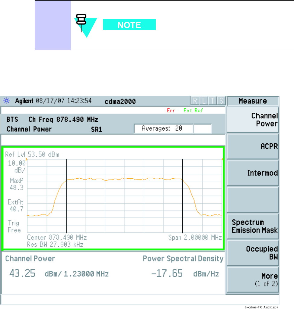
TX Audit and RSSI Tests
TX Audit The Audit is a power out test that will pass within +/ -2 dB of the expected power .
The standard pattern per S -C is 43dBm and the Audit test will pass if the output power is
within the limits listed above.
TX Audit T est Procedure P erform the procedure in Procedure 4 -1 for TX Audit.
Procedure 4 -1 Procedure for TX A udit
1
Set up test equipment for TX acceptance tests per Figure 3-23 through
Figure 3-26
2
If it has not already been done, configure the test equipment for TX path
audit as in Figure 3-23
3
Click on the devices to be tested.
4
Click T ests > TX > TX Audit
5
Select the appropriate carrier in the Channels/Carrier pick list.
Enter the channel number in the Carrier # Channels box.
T o select multiple items, hold down the Shift or CTRL key while
making the selections.
6
Click OK . The status report window is displayed and then a Directions
pop-up is displayed.
7
F ollow the cable connection directions as they are displayed. T est results are
displayed in the status report window .
Continued
4 -4 68P09283A63 -5
FOA A UG 2007
1X UBS Macro B T S Optimization/A TP Acceptance T est Procedures - TX & RX
Procedure 4 -1 Procedure for TX A udit (Continued)
8
Click Save Results or Dismiss button.
If Dismiss is selected, the test results will not be saved.
Figure 4 -1 TX A udit Signal
ti-cdma-TX_Audit.eps
68P09283A63 -5 4 -5
FOA A UG 2007

Acceptance T est Procedures - TX & RX Chapter 4: Acceptance T est Procedures
Receive Signal Strength Indication Acceptance Test
Overview This test verifies Receive Signal Strength Indication (RS SI) for the selected sectors
to ensure integrity of the reverse (RX) path, that path losses are within tolerances required for
correct receiver operation, and correct installation of the RX path. T esting is performed using
the calibrated external test equipment as the signal source. The test equipment is controlled by
the LMF during the test. The receive signal generated by the test equipment is injected into the
sector RX path to be tested at the applicable UBS main and / or diversity receive ports.
Equipment Operation During T esting The LMF sets the pilot channel power level of the
sector for the selected sector to +XX dBm (measured at the TX port of the frame) and enables
the sector -carrier on pilot channel only to enable the RX circuitry . The LMF then commands the
test equipment to generate the receive signal on the selected carrier at -80 dBm as measured
at the UBS RX port
T est Measurements The power level of the received signal is measured by the RFX. The
LMF corrects the measured power of the signal using the RX BLO and determines if the
corrected signal gain is equal to or greater than the following specified criteria for the band in
which the UBS operates:
•1900 MHz: –80 dBm ( -86 dBm or greater)
•800 MHz: –80 dBm ( -86 dBm or greater)
The LMF provides -80 dBm signal (default) input to the UBS . The RS SI must be
+/ -6 dB.
Receive Signal Strength Indicator ATP
P erform the following procedure for RS SI acceptance testing.
Procedure 4 -2 Procedure for RS SI Acceptance T esting
1
Set up the test equipment for RX acceptance tests. Reference Figure 3-23
through Figure 3-26 .
2
Select the carrier to be tested.
3
In the LMF window menu bar , click on T ests > RX > RS SI
4
Select the carrier to be tested in the Channels/Carriers pick list which is
displayed.
Continued
4 -6 68P09283A63 -5
FOA A UG 2007
1X UBS Macro B T S Optimization/A TP Acceptance T est Procedures - TX & RX
Procedure 4 -2 Procedure for RS SI Acceptance T esting (Continued)
5
Select the RX Branch to be tested from the choices in the drop down list
provided (Both, Main, Diversity)
6
Enter the appropriate power level into the Generator amplitude box (default:
-80 dBm)
7
Click OK . A status bar will be displayed followed by a Directions pop up
window .
8
F ollow cable connection directions as they are displayed, and click the
Continue button to begin testing. Progress will be indicated in the status bar .
9
When the test is completed, click Save Results or Dismiss button, as
required, in the Status Report window .
If Dismiss is selected, then the test results will not be saved.
Automated ATP
This section covers the general requirements and procedures for conducting both automated
A TP testing and performing individual A TP tests.
Automated ATP Test Options
Acceptance tests can be run individually or as one of the following automated groups:
•All TX: TX tests verify the performance of the UBS transmit line up.
•All RX: RX tests verify the performance of the UBS receiver line up.
•All TX/RX: Executes all the TX and RX tests.
•Full Optimization: Executes the TX calibration, downloads the BLO , and executes the TX
audit before running all of the TX and RX tests.
The Full Optimization test can be run if TX path calibration is needed before the TX
and RX acceptance tests are run.
The STOP button can be used to stop the testing process.
The LMF is optimized to perform the tests as quickly as possible when selecting the
“perform all" menu options. It is recommended that the user select this option on a
per sector/carrier option where possible to save time.
68P09283A63 -5 4 -7
FOA A UG 2007

Acceptance T est Procedures - TX & RX Chapter 4: Acceptance T est Procedures
Required Test Equipment
The following test equipment is required:
•LMF
•P ower Meter
•Communications System Analyzer
•Before connecting an y test equipment directly to an y UBS TX OUT connector ,
verify that there are no CDMA channels keyed .
•A t activ e sites, ha v e the OMC -R oper ator place the carrier assigned to the UBS
under test OOS . F ailure to do so can result in serious personal injury and/or
equipment damage.
T est equipment must be calibrated and the cables re -calibrated before using them to
perform acceptance tests.
ATP Test Prerequisites
Before attempting to run any A TP tests, ensure the following have been completed:
•LMF is logged into the UBS .
•All FRUs on the LMF screen are INS (Green)
•T est cables are calibrated
•T est equipment is connected for A TP tests (refer to A TP T est Setup illustrations in the T est
Equipment Set Up section of Appendix E Optimization and Calibration Procedures )
•T est equipment has been selected in the LMF , warmed up 60 minutes and calibrated
•All required Ethernet test equipment connections are made
•UBS transmit connectors are terminated with either non -radiating loads or connected to
the test equipment as specified in Figure 3 -27 through Figure 3 -30 .
4 -8 68P09283A63 -5
FOA A UG 2007
1X UBS Macro B T S Optimization/A TP Acceptance T est Procedures - TX & RX
Before a FER test is run, be sure that the following is done:
All tr ansmitter connectors are properly terminated. T erminations should be 50 -Ohms,
200 W . F ailure to observ e these w arnings ma y result in bodily injury or equipment
damage.
Procedure 4 -3 Setup T est Equipment — TX Output V erif y/Control T ests
1
If it has not already been done, interface the LMF computer to the UBS .
2
If it has not already been done, refer to Procedure 3-3 to start a GUI LMF
session and log into the UBS .
3
If it has not already been done, refer to Figure 3-23 ,Figure 3-24 ,Figure 3-25 ,
or Figure 3-26 as applicable, for the test equipment and antennas being used,
to connect test equipment for acceptance testing.
LMF -based measurements factor in TX cable loss between the UBS
and the test equipment.
Antenna Connectors
All acceptance testing requires test equipment connections to the UBS antenna TX or RX
connectors. Refer to the A TP T est Setup illustrations in the T est Equipment Set Up section of
Appendix E Optimization and Calibration Procedures for specific connection requirements
Recommended Tests
The recommended tests are TX Audit and Receive Signal Strength Indicator (RS SI) to confirm
the physical assembly of the frame and that all the cables TX, RX, Digital etc are correctly
connected. The rest of the tests are supported, optional, or for troubleshooting purposes.
TX/RX ATP Test Procedure
F ollow the procedure in Procedure 4 -4 to perform the All TX/RX A TP test.
Procedure 4 -4 All TX/RX A TP T est Procedure
Continued
68P09283A63 -5 4 -9
FOA A UG 2007
Acceptance T est Procedures - TX & RX Chapter 4: Acceptance T est Procedures
1
Set up the test equipment for abbreviated tests per Procedure 4-3
2
Select the device(s) to be tested.
T o select multiple items, hold down the Shift or Ctrl key while
making the selections.
F or all TX tests except Code domain, a SectorCarrier must be
selected. F or code domain select the modem and carrier . F or RX
test — FER select the modem and SectorCarrier . F or RX test —
RS SI select SectorCarrier only .
3
Click on T ests in the UBS Menu bar , and select All TX/RX A TP ... from
pull-down menu.
4
Select the appropriate SectorCarrier (carrier-bts#-sector#-carrier#)
displayed in the Channels/Carrier pick list.
Since the UBS supports OMNI configurations only , sector# will
always be 1.
5
V erify that the correct channel number for the selected
SectorCarrier is shown in the Carrier # Channels box.
If not obtain the latest bts-#.necf files.
If necessary , the correct number may be manually entered into
the Carrier # Channels box.
6
Select the appropriate RX Branch (Both,
Main, or Diversity ) from the drop-down menu.
In the R ate Set box, select the appropriate data rate (1=9600, 2= 14400, 3 =
9600 1X) from the drop-down list.
7
In the T est P attern box, select the Standard test pattern from the drop
down list in the Bay Level Offset Calibration section.
8
Click on the OK button.
The status report window and a Directions pop-up are displayed.
9
F ollow the cable connection directions as they are displayed.
The test results are displayed in the status report window .
Continued
4 -10 68P09283A63 -5
FOA A UG 2007
1X UBS Macro B T S Optimization/A TP Acceptance T est Procedures - TX & RX
Procedure 4 -4 All TX/RX A TP T est Procedure (Continued)
10
Click on Save Results or Dismiss .
If Dismiss is used, the test results will not be saved in the test
report file.
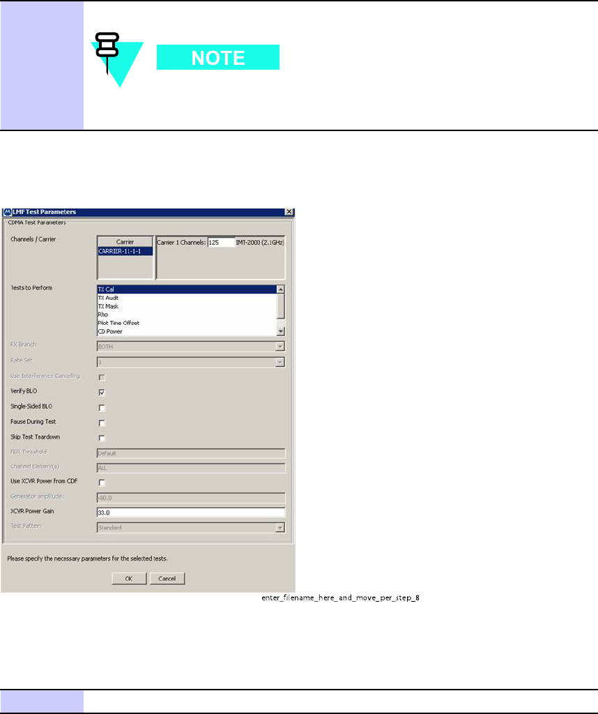
Figure 4 -2 TX T est Options Screen
enter_filena me_her e_a nd_mo ve_per_step_8
P erform the procedure in Procedure 4 -5 for all -inclusive transmit test.
Procedure 4 -5 All TX A TP T est
1
Set up the test equipment for TX acceptance tests per Procedure 4-3
Continued
68P09283A63 -5 4 -11
FOA A UG 2007
Acceptance T est Procedures - TX & RX Chapter 4: Acceptance T est Procedures
Procedure 4 -5 All TX A TP T est (Continued)
2
On LMF , select devices to be tested.
T o select multiple items, hold down the Shift or Ctrl key while
making the selections.
3
Click on T ests in the BTS Menu bar , and select All TX A TP ... from pull-down
menu.
4
Select the appropriate carrier (HDModem) from those displayed in the
Channels/Carrier pick list.
5
V erify that the correct channel number for the selected
carrier is shown in the Carrier # Channels box.
If not obtain the latest bts-#.necf files.
If necessary , the correct number may be manually entered into
the Carrier # Channels box.
6
In the T est P attern box, select the Standard test pattern from the drop
down list in the Bay Level Offset Calibration section. Other selections are
available for TX Mask only .
7
Click OK to display a status bar followed by a Directions pop-up window .
8
F ollow the cable connection directions as they are
displayed, and click the Continue button to begin testing.
As the A TP process is completed, results will be displayed in a status report
window .
9
Click the Save Results or Dismiss button.
If Dismiss is used, the test results will not be saved in the test
report file.
4 -12 68P09283A63 -5
FOA A UG 2007