Opticon Sensors Europe PHL7200-BW Portable Data Terminal User Manual 5 rev
Opticon Sensors Europe BV Portable Data Terminal 5 rev
Contents
User manual 5 rev
OPTICON
User's manual
PHL-7000 series
3
-
7
RSS-expanded Enable RSS-expanded
DataMatrix
ECC000-ECC140
Enable DataMatrix ECC000-ECC140
DataMatrix ECC200 Enable DataMatrix ECC200 (default)
Aztec Enable Aztec (default)
Aztec Runes Enable Aztec Runes
QR Code Enable QR Code (default)
Maxi Code Enable Maxi Code (default)
PDF417 Enable PDF417 (default)
MicroPDF417 Enable MicroPDF417 (default)
Table 3-17 Code configure description 2D CMOS
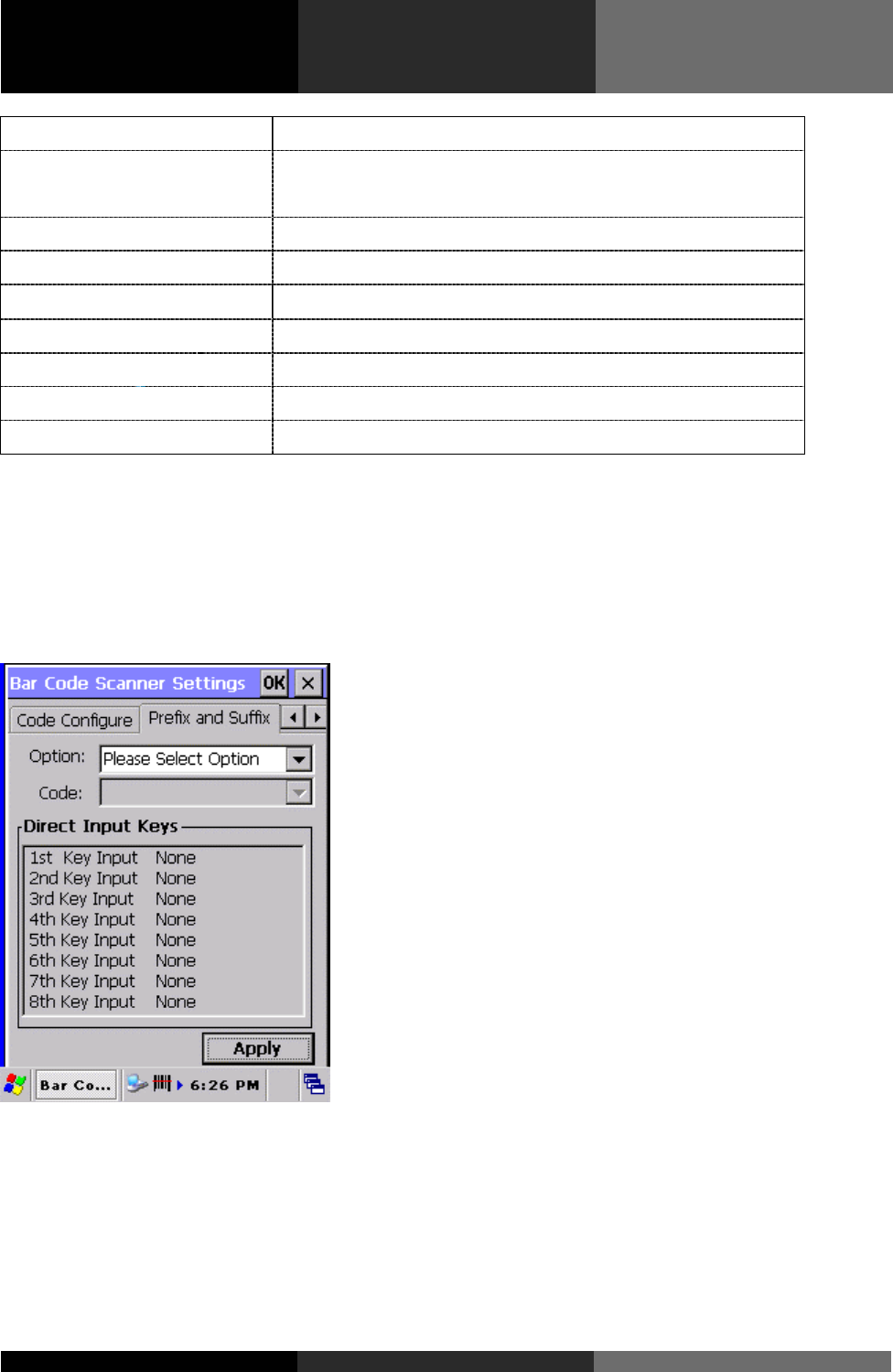
3.2.1.3 Prefix and suffix TAB
With these options alterations can be made to the format of the transmitted data string.
Figure 3-2 Prefix and Suffix Tab
Options available are :
- Transmission of a preamble,
- Transmission of a prefix,
- Transmission of a suffix,
OPTICON
User's manual
PHL-7000 series
3
-
8
- Transmission of a postamble.
The transmitted string format is :
Figure 3-2 Transmitted string format
A prefix and suffix of maximum 4 direct input entries each may be included in front and at the end of
the string respectively. A preamble is transmitted before the prefix and can contain up to 8 direct
input characters. A postamble is transmitted after the suffix and can contain up to 8 direct input
characters. A preamble and postamble will be transmitted for all symbologies.
Default settings are :
- Preamble : None
- Prefix : None
- Suffix : ^M (CR)
- Postamble : None
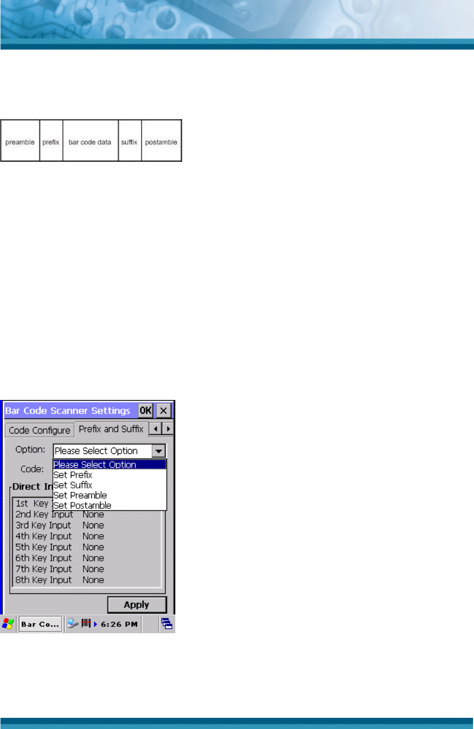
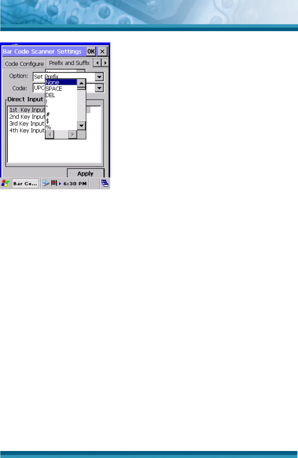
Tap the “Please Select Option” field to select one of above mentioned options :
Figure 3-2 Prefix and Suffix, select Option list box
Select one of these 4 options which meet your requirement.
OPTICON
User's manual
PHL-7000 series
3
-
9
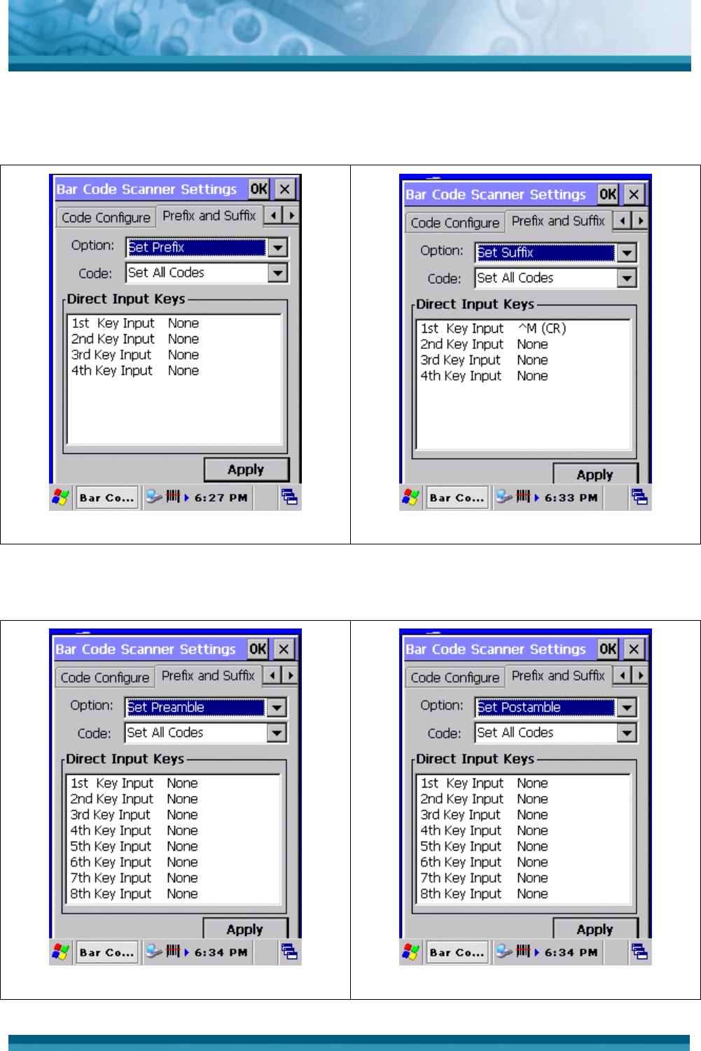
In the Prefix and Suffix option, 4 key input fields and their current settings are shown :
Figure 3-2 Prefix option
Figure 3-2 Suffix option
The default suffix is ^M (CR) .
In the Preamble and Postamble option, 8 key input fields and their current settings are shown :
Figure 3-2 Preamble optio
Figure 3-2 Postamble optio
OPTICON
User's manual
PHL-7000 series
3
-
10
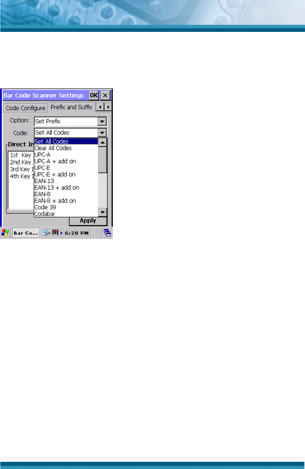
In the code option field can be indicated for which symbology the current prefix or suffix should be
configured. The “Clear All Codes” options will clear the prefix for all symbologies.
Figure 3-2 Prefix : Code list box.
Example : to set the characters “UPCA” for bar code symbology UPC-A, tap in the “Direct Input
Keys” section, the field “1st Key Input”. A list box will popup, which shows all 128 ASCII characters.
SPACE is the <Space> character (ASCII 32dec, 20hex). DEL is the <DEL> character 127dec 7Fhex.
Scroll downwards to the character ‘U’ and tap the character ‘U’.
OPTICON
User's manual
PHL-7000 series
3
-
11
Figure 3-2 Prefix : Direct input keys selection box.
OPTICON
User's manual
PHL-7000 series
3
-
12
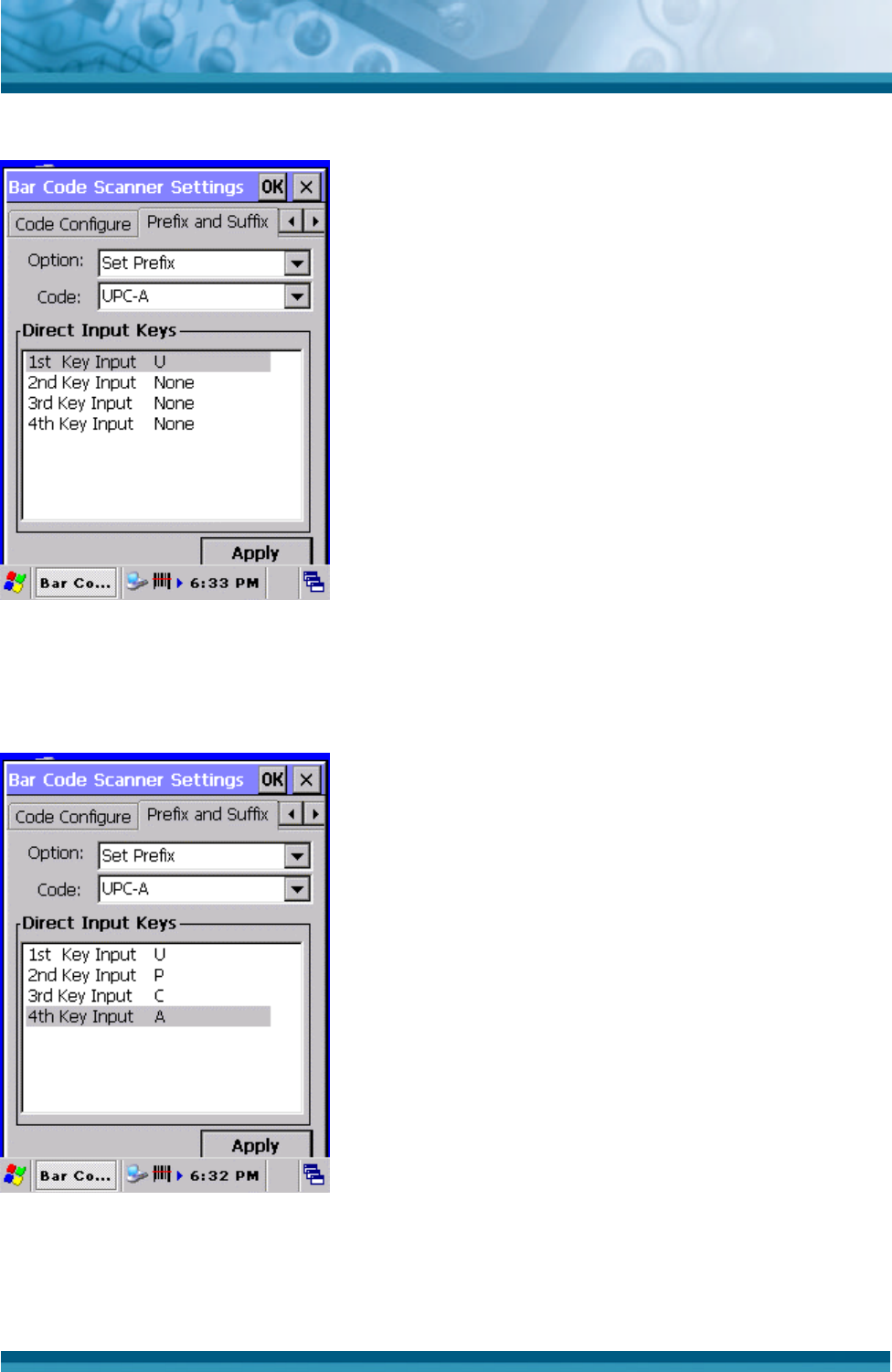
Thereafter the display will look like :
Figure 3-2 Prefix : Selected character ‘U’ for UPC-A..
Repeat these steps for the characters ‘P’, ‘C’ and ‘A’.
Thereafter the display will look like :
Figure 3-2 Prefix : Selected characters ‘UPCA’ for UPC-A..
If the bar code reader reads an UPCA label with data ‘071589812309’, it will be send to the
application as : ‘UPCA071589812309<CR>’ where <CR> is the default suffix ASCII character
<CR>.
OPTICON
User's manual
PHL-7000 series
3
-
13
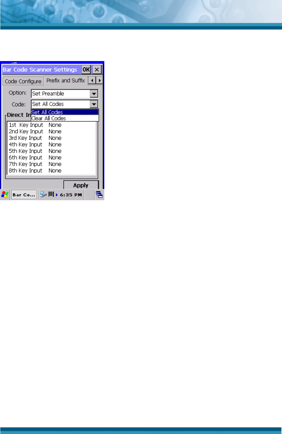
Preamble and postamble are applicable for all bar code symbologies. Therefore the code
option list box shows only 1 option : “Clear all codes”.
Figure 3-2 Preamble : Only 1 code option.
OPTICON
User's manual
PHL-7000 series
3
-
14
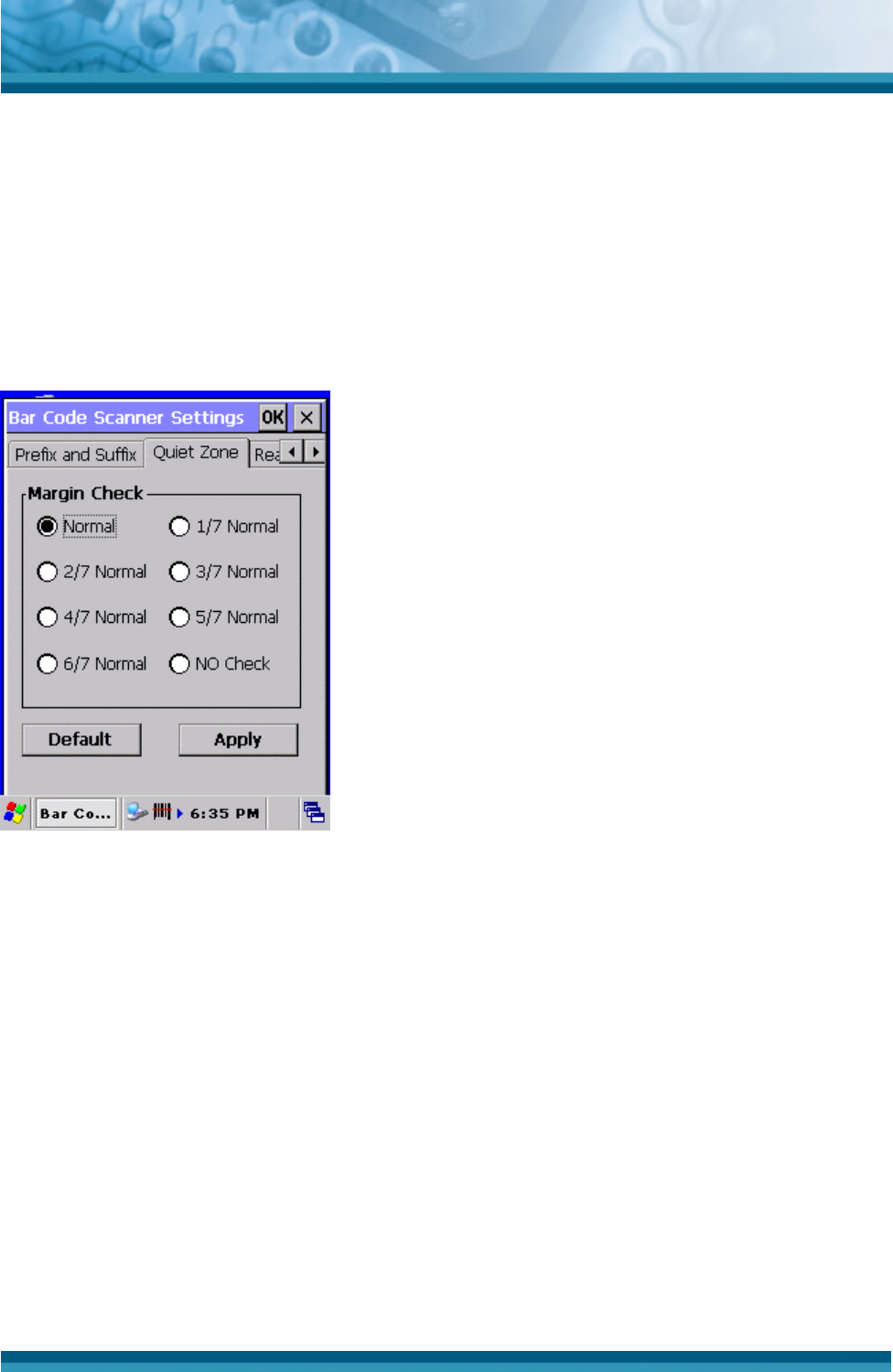
3.2.1.4 Quiet zone TAB
With this option the reader can decode bar codes that have smaller start and/or end margins
than specified for the symbology. Be carefully when using this option. It may increase the
possibility of partial reads and ghost reads. Do not use smaller margin checks then
necessary. If possible replace the bar code labels by ones that have correct start and end
margins.
Figure 3-2 Quiet zone options.
OPTICON
User's manual
PHL-7000 series
3
-
15
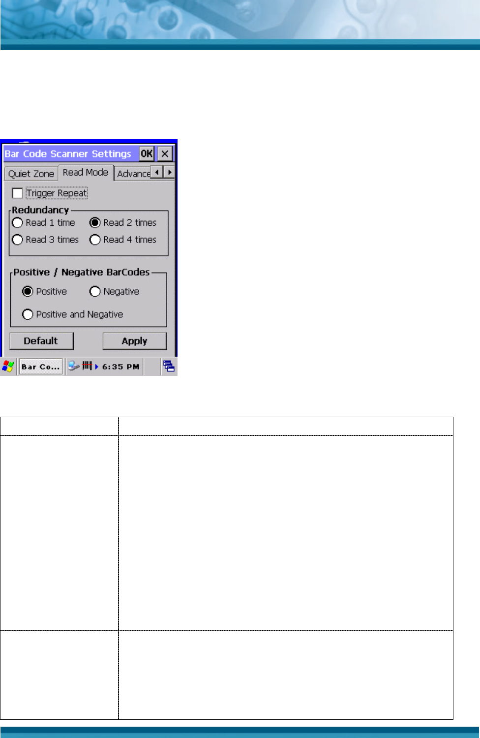
3.2.1.5 Read Mode TAB
With this option several read modes can be changed.
Figure 3-2 Read mode options.
Field name Description
Trigger repeat This option makes it more easy to select a single bar code
from a sheet filled with barcodes. If the trigger switch is
pressed once, the laser beam is on during the configured read
time. The laser beam can now be moved to the required bar
code. If the trigger switch is pressed again, the bar code is
decoded and transmitted. If the read time timer expires, the
laser switches off and the trigger sequence should be
repeated. If the read time is set to zero, then if the trigger
switch is pressed, the laser is on, but does not accept bar
codes. As soon the trigger switch is released, the barcode is
decoded and transmitted. Default is disabled.
Redundancy This is the number of times that a label must be correctly
decoded before it is transmitted. Selecting a higher
redundancy count makes reading slower, but is reduces the
probability of reading errors, especially when labels of poor
definition are used.
OPTICON
User's manual
PHL-7000 series
3
-
16
Read 1 time Redundancy = 0
Read 2 times Redundancy = 1 (default)
Read 3 times Redundancy = 2
Read 4 times Redundancy = 3
Usually bar codes are printed black on white, but sometimes
white on black. These labels are called positive and negative
respectively. In case the ‘negative bar codes’ option has been
selected, positive labels may not be decoded or with difficulty.
Positive bar codes Read black on white labels only
(default)
Negative bar codes Read white on black labels only
Positive / Negative
bar codes
Positive and
negative bar codes
Read positive or negative labels
automatically.
Table 3-17 Read mode options descriptions
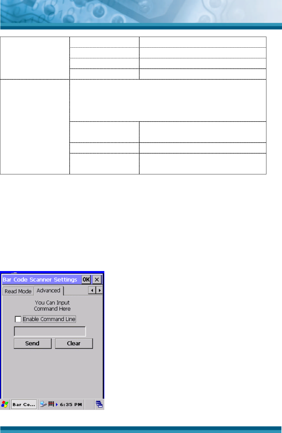
3.2.1.6 Advanced TAB
If enabled, this field can be used to send serial commands to the bar code reader.
Use this option only in case you want to access bar code reader features which are not
documented in this user’s manual, but are documented in Opticon’s Universal Menu Book.
If there is no need to make any other change to the bar code reader settings, do not use this
option. A maximum of 180 characters can be input. Default this option is disabled.
Figure 3-2 Command line options.
OPTICON
User's manual
PHL-7000 series
3
-
17
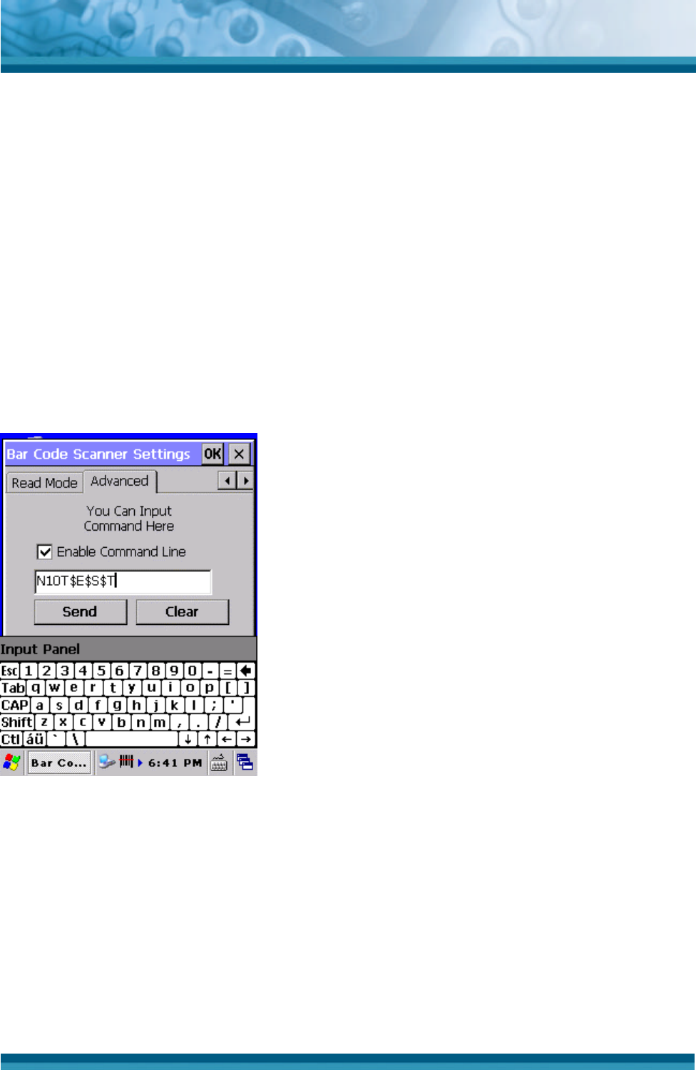
Example :
To set a prefix ‘Test’ for UPC-A, lookup in Opticon’s Universal Menu Book (UMB) the serial
command’s of :
- prefix UPC-A : see UMB paragraph 4.2.1, serial command = N1
- Direct input ‘T’ : see UMB paragraph 4.3.4, serial command = 0T
- Direct input ‘e’ : see UMB paragraph 4.3.5, serial command = $E
- Direct input ‘s’ : see UMB paragraph 4.3.5, serial command = $S
- Direct input ‘t’ : see UMB paragraph 4.3.5, serial command = $T
Input these 5 commands into the Command line field by using the keyboard Input panel.
If the Send button is pressed, the serial command sequence is send to the bar code reader.
To save the settings in the bar code reader, add the commands Z2 after the last command
sequence.
See picture below :
Figure 3-2 Example of command line usage.
OPTICON
User's manual
PHL-7000 series
3
-
18
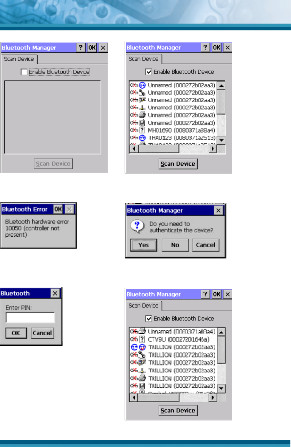
3.2.2 Bluetooth Device Properties
ICON ITEM & FUNCTION
• “Scan Device” Tab ( Figure 3-25) :
ü Tap the Scan Device button to initiate a scan for Bluetooth
devices. The Bluetooth manager lists the Bluetooth devices
that it finds, see Figure 3-26. If Bluetooth hardware is not
found in the PDT, the Bluetooth Hardware Error window
appears, see Figure 3-27. Table 3-18 described the
Bluetooth Icons.
ü Double tap the device to connect to on the device list. The
Bluetooth Manager Authentication window appears. Tap
No to connect to the device without authentication, or tap
Yes to authenticate the device before connecting. (Figure
3-28)
ü If the Yes button was selected in the Bluetooth Manager
Authentication window, the enter PIN windows appears.
Enter a PIN (between 1 and 16 alpha numeric characters)
in the Enter PIN: text box, and tap OK. The mobile
computer sends the PIN request to the device for bonding.
(Figure 3-29)
ü When prompted, the same PIN must be entered on the
other device. When the PIN is entered correctly on the
other device, the bonded icon appears on the device
list. (Figure 3-30)
Table 3-17 Bluetooth Device Properties
OPTICON
User's manual
PHL-7000 series
3
-
19
Figure 3-25 Bluetooth Manager Window Figure 3-26 Bluetooth Manager Window
Figure 3-27 Bluetooth Error Window Figure 3-28 Bluetooth Manager Window
Figure 3-29 Bluetooth Enter PIN Window Figure 3-30 Bluetooth Manager Window