Opticon Sensors Europe PHL7200-BW Portable Data Terminal User Manual 8 rev
Opticon Sensors Europe BV Portable Data Terminal 8 rev
Contents
User manual 8 rev
OPTICON
User's manual
PHL-7000 series
3
-
40
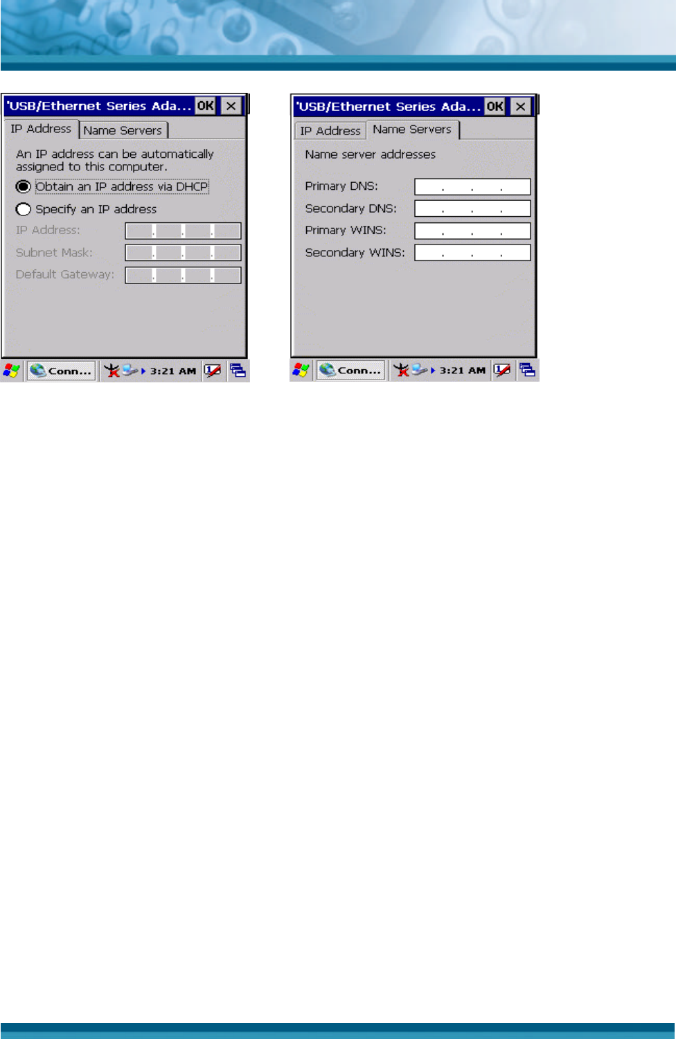
Figure 3-70 Network and Dial-up
Connections
Figure 3-71 Network and Dial-up
Connections
OPTICON
User's manual
PHL-7000 series
3
-
41
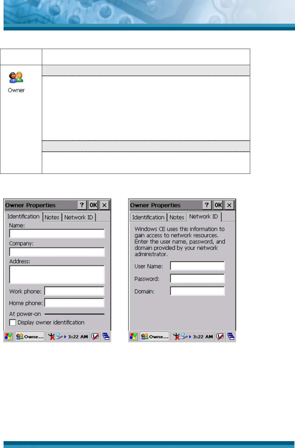
3.2.12 Owner
ICON ITEM & FUNCTION
• “Identification” Tab : (Figure 3-74)
ü Fill in or edit the data as desired.
ü To have this information displayed when you start your
device, select “Display Owner Identification” at Power
On.
ü To set up identification for remote networks, see Setting up
identification for remote networks.
• “Network ID” Tab: (Figure 3-75)
ü Enter the user name, password, and domain name you use
to log on to remote network.
Table 3-32 Owner
Figure 3-72 Owner Properties Figure 3-73 Owner Properties
OPTICON
User's manual
PHL-7000 series
3
-
42
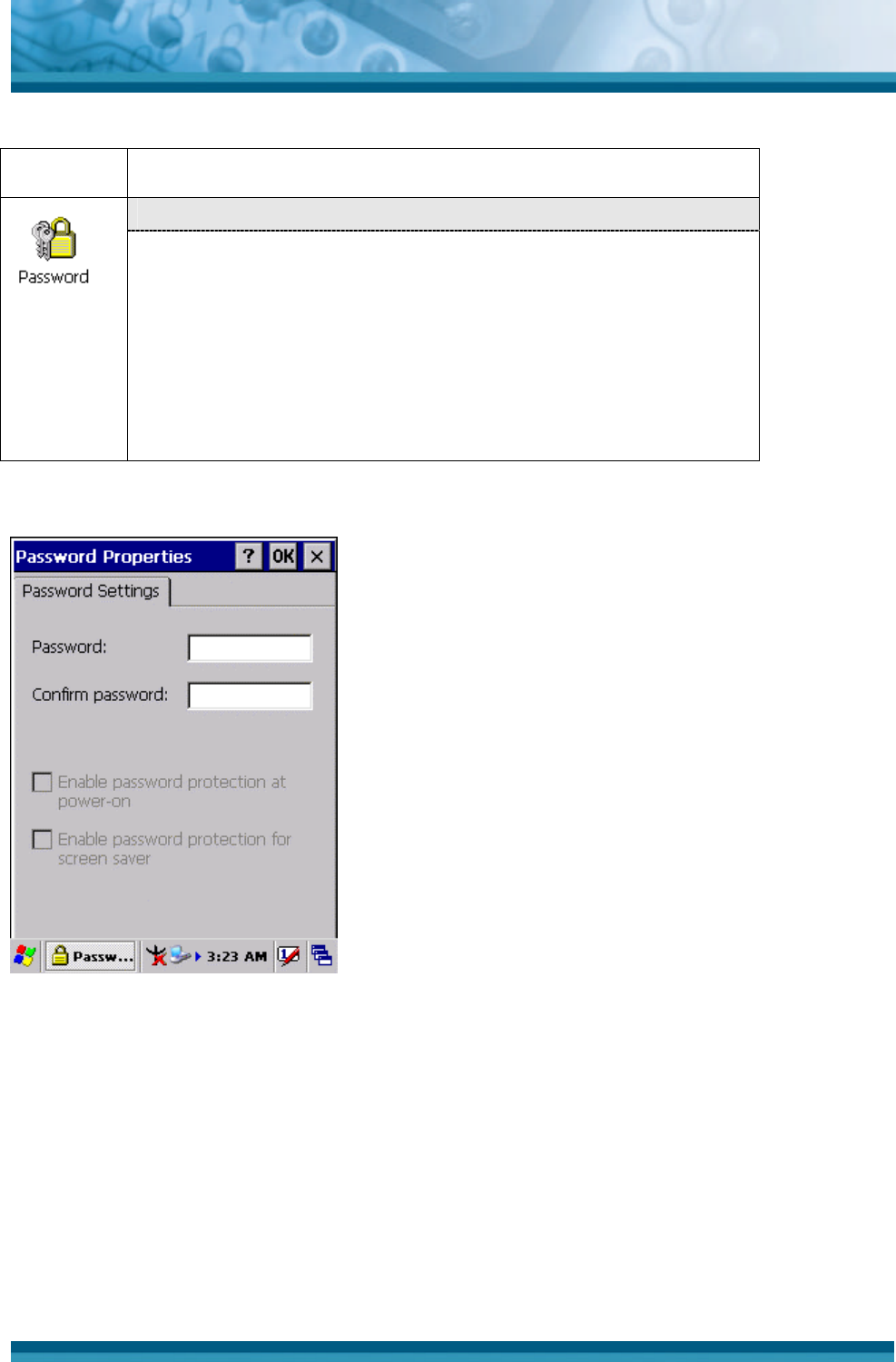
3.2.13 Password
ICON ITEM & FUNCTION
• “Password Setting” Tab : (Figure 3-76)
ü Enter the password
ü In the “Confirm password “box, enter the password again.
ü To require the password on startup, select “Enable
password protection at power- on“. and/or select
“Enable password protection for screen saver”
ü To exit the Password control panel, press “OK” from the
control bar, or press the <Enter> key on the keypad.
Table 3-33 Password
Figure 3-74 Password Properties
OPTICON
User's manual
PHL-7000 series
3
-
43
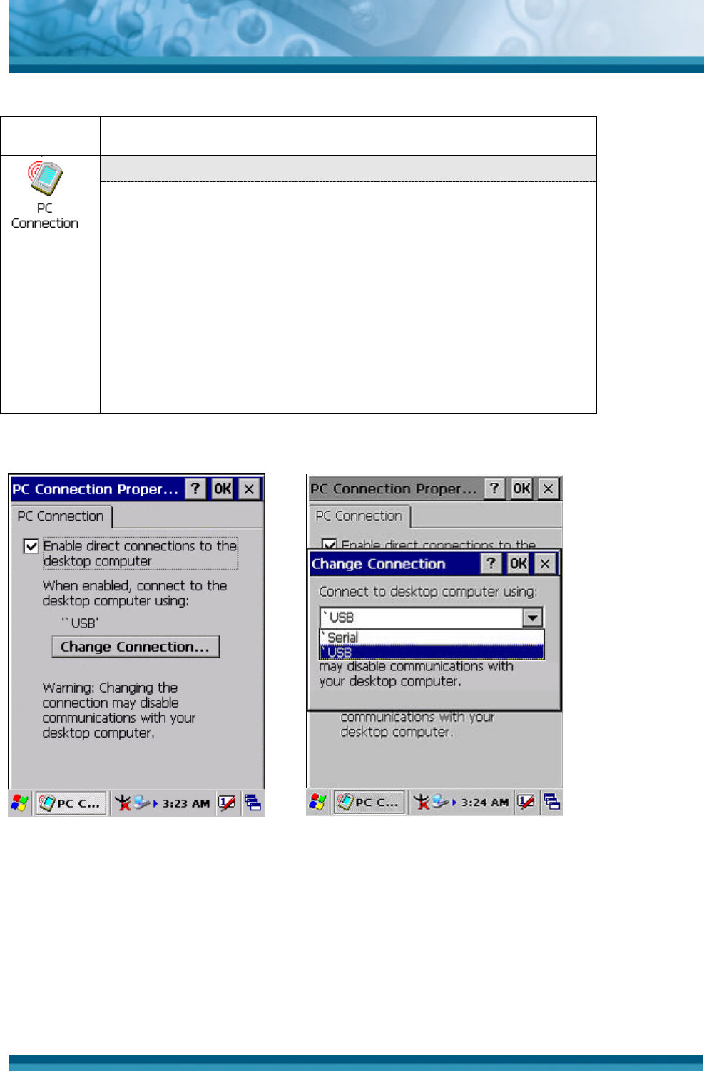
3.2.14 PC Connection
ICON ITEM & FUNCTION
• “PC Connection” Tab : (Figure 3-77)
ü Select the first checkbox to enable direct connections to the
desktop computer. (Figure 3-77)
ü Tap the “Change Connection… ” button to modify the
connection method from USB or Serial. (Figure 3-78)
ü To exit the “Change Connection” dialog, press “OK” from
the control bar, or press the <Enter> key on the keypad.
ü To exit the “PC Connection” properties control panel,
press “OK” from the control bar, or press the <Enter> key
on the keypad.
Table 3-34 PC Connection
Figure 3-75 PC Connection Figure 3-76 PC Connection
OPTICON
User's manual
PHL-7000 series
3
-
44
3.2.15 Power
ICON ITEM & FUNCTION
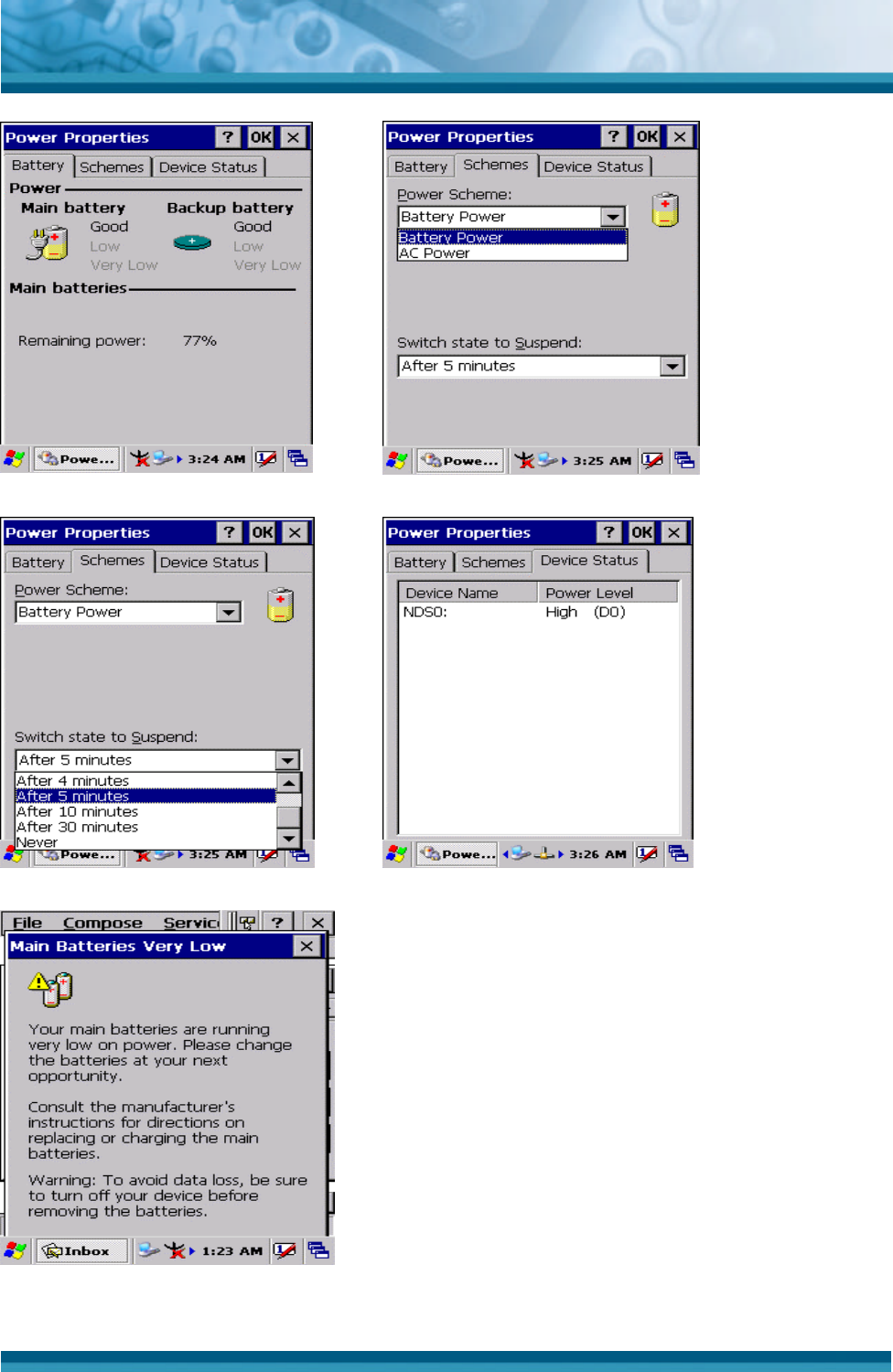
• “Battery” Tab : (Figure 3-79)
ü Provide change level indicators for Main battery and
Backup battery.
ü Provide remaining power capacity of main battery.
ü If a “Main Batteries very Low” warning message shows, the
remaining battery life is around 30 minutes before PDT
shuts down. ( Figure 3-83)
ü The PDT will shutdown if the main batteries capacity is
around 0%
ü To exit Battery control panel, press “OK” from the
command bar, or press <Enter> key on keypad.
• “ Schemes” Tab: (Figure 3-80)
ü The Scheme Tab allows you to determine the time to
switch state to Suspend mode when using either Battery
Power or AC Power.
ü Select Battery Power or AC Power as the power scheme
from the pull-down list.( Figure 3-80)
ü Select the time to suspend mode from the pull-down list.
( Figure 3-81)
• “Device Status” Tab: ( Figure 3-82)
Provide power level of the device – The power level ranges
from “ High(D0)” which means the device is at the highest
power level to “Off(D4)” which means the device is at the lowest
power level.
Note:
This ICON inside the Task Bar shows that AC adapter provides
power to the PDT
The ICON inside the Task Bar shows that Main Batteries
provides the power to the PDT.
The ICON inside the Task Bar shows that AC adapter provides
the power to the PDT and is charging the main batteries..
Table 3-35 Power
OPTICON
User's manual
PHL-7000 series
3
-
45
Figure 3-77 Power Figure 3-78 Power
Figure 3-79 Power Figure 3-80 Power
Figure 3-81 Power
OPTICON
User's manual
PHL-7000 series
3
-
46
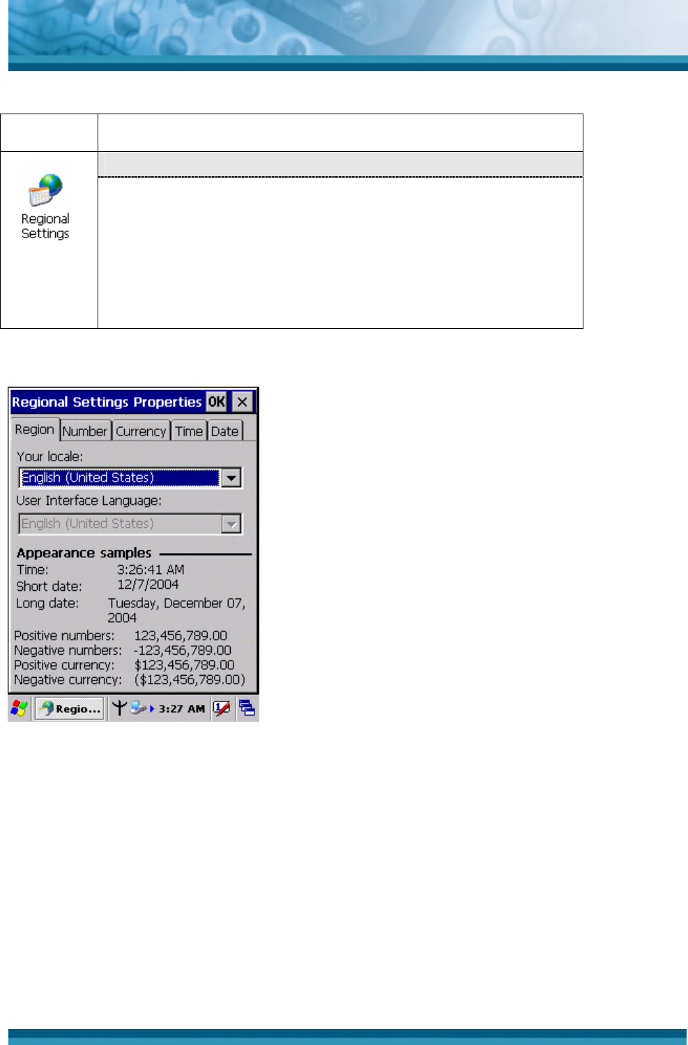
3.2.16 Regional Settings
ICON ITEM & FUNCTION
• “Region” Tab : (Figure 3-84)
ü Select the desired location/language.
ü Review the Appearance samples in the bottom half of the
screen.
ü Select the Tab at the top for any settings you wish to
change, Options to modify include Number, Currency,
Time, and Date.
Table 3-36 Regional Settings
Figure 3-82 Regional Settings
OPTICON
User's manual
PHL-7000 series
3
-
47
3.2.17 Remove Programs
ICON ITEM & FUNCTION
• “Remove Programs” Tab :
ü Only user installed programs can be removed.
Ø Select the program you wish to remove from the list and
press “remove” button.
Table 3-37 Remove Programs
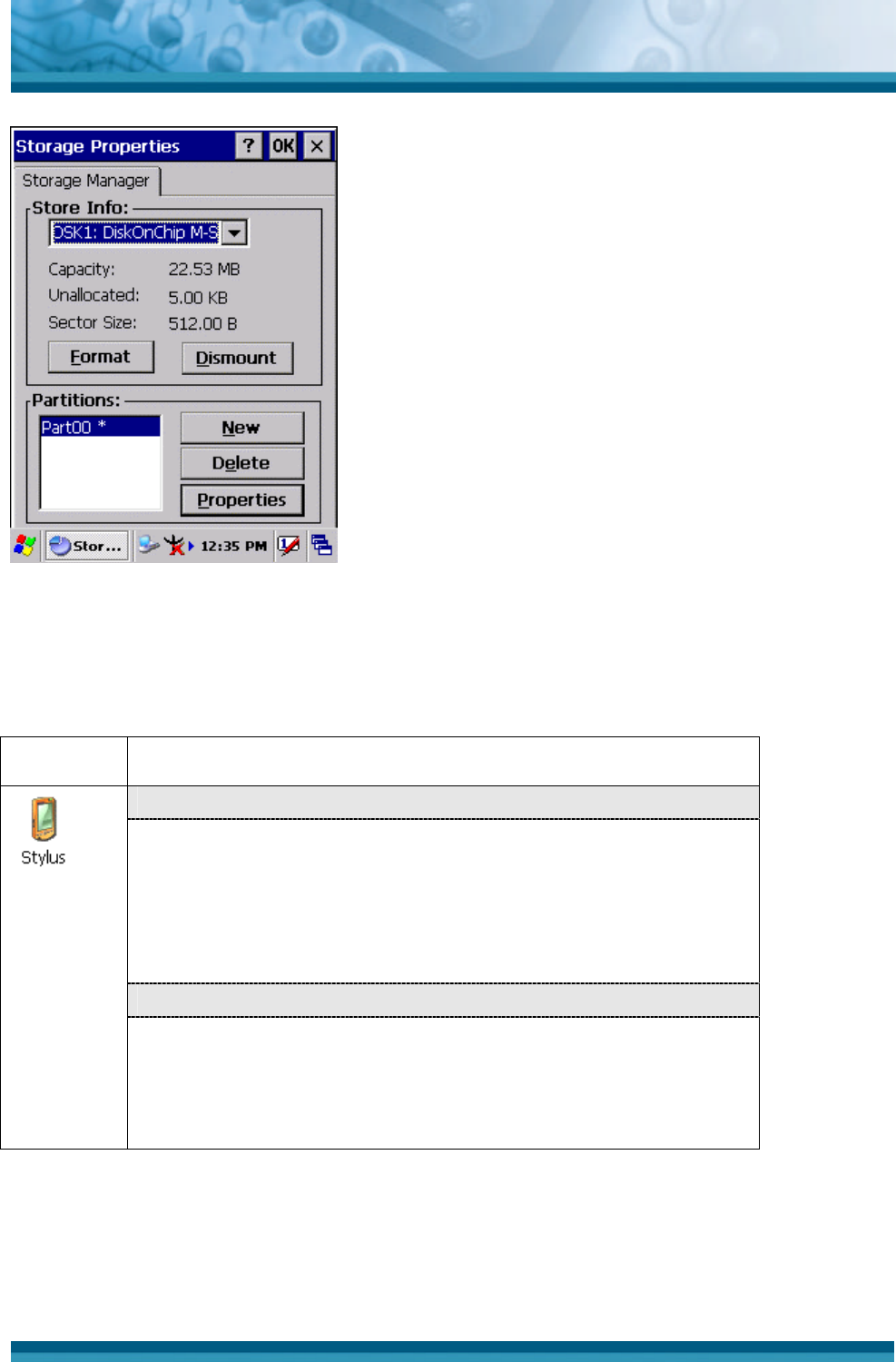
3.2.18 Storage Manager
ICON ITEM & FUNCTION
• “Storage Manager” Tab : (Figure 3-83)
ü To change Storage properties control panel default
settings:
Insert Compact Flash(CF) or Secure digital (SD) storage card
into the unit.
Ø Select Start > Settings > Control Panel > Storage
Properties
Ø From the “Storage Info” pull-down list, select the desired
storage device.
Ø You can also format, dismount, and create partitions on
storage devices using this control panel.
Ø To save and exit the Storage Properties control panel,
press “OK” from the control bar, or press the <Enter> key
on the keypad.
Caution: Dismounting or formatting the DiskOnChip
will erase all files and program stored in Flash Memory
Table 3-38 Storage Manager
OPTICON
User's manual
PHL-7000 series
3
-
48
Figure 3-83 Storage Manager
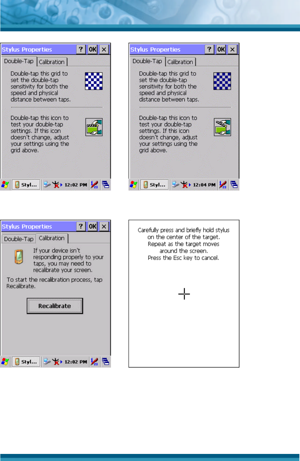
3.2.19 Stylus
ICON ITEM & FUNCTION
• “Double-Tap” Tab : (Figure 3-86,Figure 3-87)
ü Double-tap the checkerboard grip at a comfortable speed.
ü Double-tap clapboard to test your settings.
ü The function is OK if the figures are changed from Figure
3-86 to Figure 3-87.
ü To tap “OK” to exit the Stylus Properties.
• “Calibration”: (Figure 3-88, Figure 3-89)
ü In the Welcome Wizard, you tapped a target with the stylus
to set the amount of pressure needed for the screen to
respond to your stylus taps.
ü Please also see 2.4.3 Calibration of the touch Screen
Table 3-39 Stylus
OPTICON
User's manual
PHL-7000 series
3
-
49
Figure 3-84 Stylus Properties Figure 3-85 Stylus Properties
Figure 3-86 Stylus Properties Figure 3-87 Stylus Properties